Use & Care Guide
Manual de Uso y Cuidado
English / EspaKol
Models/Modelos: 790.4911 _
Elite
®
@
{o oi
@
I0_
Co®_in®ci6n Mi
":_'_::::::Color numbe_ nOmero de color
.................orno de
P/N 807574402B (1505)
Sears Brands Management Corporation
Haft:man Estates, IL 60179 U.S.A.
www.kenmore.com
Sears Canada Inc., Toronto,
Ontario, Canada M5B 2C3
WWW.Sea rs.ca
Table of Contents
Kenmore Elite Warranty .................................................... 2
IMPORTANT SAFETY INSTRUCTIONS .......................... 3=6
Product Record ................................................................. 6
Serlal Plate Location ......................................................... 6
Microwave / Wall Oven Features ..................................... 7
Microwave Oven Important lnformatlons ...................... 8=9
Control Pad Features ...................................................... 10
Control Pan Settings & Microwave Menu Label ................ 11
Oven Vent and Racks ................................................. 12=13
Getting Started ............................................................... 14
Microwave Manual Operation ......................................... 15
Microwave Operating Instructlons .............................. 16-25
Lower Oven Operation Instructlons ............................ 26=35
User Preferences ............................................................. 36
Lower Oven Self=Cleanlng Cycle ............................... 37=38
Microwave General Care & Cleaning ............................. 39
Lower Oven General Care & Cleaning ...................... 40=42
Before You Caff ......................................................... 43=45
Protection Agreements .................................................... 47
Sears Service .................................................................. 48
Please carefully read and save these instructions
This Use & Care Manual contains general operating instructions for your appliance and feature information for several
models. Your product may not have all the described features. The graphics shown are representative. The graphics on your
appliance may not look exactly like those shown. Common sense and caution must be practiced when installing, operating
and maintaining any appliance.
KENMORE ELITE LIMITED WARRANTY
FOR ONE YEAR from the date of sale this appliance is warranted against defects in material or workmanship when it is
correctly installed, operated and maintained according to all supplied instructions.
WITH PROOF OF SALE, a defective appliance will receive free repair or replacement at option of seller.
For warranty coverage details to obtain free repair or replacement, visit the web page: www.kenmore.com/warranty
This warranty applies for only 90 DAYS from the sale date in the United States, and is void in Canada, if this appliance is
ever used for other than private household purposes.
This warranty covers ONLY defects in material and workmanship, and will NOT pay for:
1. Cracks in a ceramic glass cooktop that are not a result of thermal shock.
2. Stains and scratches on a ceramic glass cooktop resulting from accident or improper operation or maintenance.
3. Discoloration of cooktop surfaces resulting from normal use.
4. Expendable items that can wear out from normal use, including but not limited to filters, belts, bags or screw-in base light
bulbs.
5. A service technician to clean or maintain this appliance, or to instruct the user in correct appliance installation, operation
and maintenance.
6. Service calls to correct appliance installation not performed by Sears authorized service agents, or to repair problems
with house fuses, circuit breakers, house wiring, and plumbing or gas supply systems resulting from such installation.
7. Damage to or failure of this appliance resulting from installation not performed by Sears authorized service agents,
including installation that was not in accord with electrical, gas or plumbing codes.
8. Damage to or failure of this appliance, including discoloration or surface rust, if it is not correctly operated and
maintained according to all supplied instructions.
9. Damage to or failure of this appliance, including discoloration or surface rust, resulting from accident, alteration, abuse,
misuse or use for other than its intended purpose.
10. Damage to or failure of this appliance, including discoloration or surface rust, caused by the use of detergents, cleaners,
chemicals or utensils other than those recommended in all instructions supplied with the product.
11. Damage to or failure of parts or systems resulting from unauthorized modifications made to this appliance.
12. Service to an appliance if the model and serial plate is missing, altered, or cannot easily be determined to have the
appropriate certification logo.
Disclaimer of implied warranties; limitation of remedies
Customer's sole and exclusive remedy under this limited warranty shall be product repair or replacement as provided herein.
Implied warranties, including warranties of merchantability or fitness for a particular purpose, are limited to one year or the
shortest period allowed by law. Seller shall not be liable for incidental or consequential damages. Some states and provinces
do not allow the exclusion or limitation of incidental or consequential damages, or limitation on the duration of implied
warranties of merchantability or fitness, so these exclusions or limitations may not apply to you.
This warranty applies only while this appliance is used in the United States and Canada. _
This warranty gives you specific legal rights, and you may also have other rights which vary from state to state.
In-home repair service is not available in all Canadian geographical areas, nor will this warranty cover user or servicer
travel and transportation expenses if this product is located in a remote area (as defined by Sears Canada Inc.) where an
authorized servicer is not available.
Sears Brands Management Corporation, Hoffman Estates, IL 60179
Sears Canada Inc., Toronto, Ontario, Canada M5B 2C3
2 Printed in U.S.A.
iMPORTANT SAFETY iNSTRUCTiONS
Read all instructions before using this appliance.
This manual contains important safety symbols and instructions. Please pay attention to these
symbols and follow all instructions given.
This symbol will help alert you to situations that may cause serious bodily harm, death
or damage.
This symbol will help alert you to situations that may cause bodily injury or property
damage.
PRECAUTIONS TO AVOID POSSIBLE EXPOSURE TO
EXCESSIVE MICROWAVE ENERGY
For your safety the information in this manual must be followed to minimize the risk of fire or
explosion or to prevent property damage, personal injury or loss of life.
* Do Not Attempt to operate this microwave oven with the door open since open-door
operation can result in harmful exposure to microwave energy. It is important not to defeat or
tamper with the safety interlocks.
* Do Not Place any object between the microwave oven front face and the door or allow soil
or cleaner residue to accumulate on sealing surfaces.
* Do Not Operate the microwave oven if it is damaged. It is particularly important that the
microwave oven door close properly and that there is no damage to the: 1. door (bent); 2.
hinges and latches (broken or loosened); 3. door seals and sealing surfaces.
* The Oven Should Not be adjusted or repaired by anyone except properly qualified service
personnel.
" Remove all tape and packaging before
using the appliance. Destroy the carton and
plastic bags after unpacking the appliance.
Never allow children to play with packaging
material.
* Proper installation. Be sure your appliance
is properly installed and grounded by a
qualified technician in accordance with
the National Fuel Gas Code ANSi Z223-
latest edition, or in Canada CAN/CGA
B149.1 and CAN/GGA B149.2, and the
National Electrical Code ANSI/NFPA No.70-
latest edition, or in Canada CSA Standard
C22.1, Canadian Electrical Code, Part 1,
and local code requirements. Install only
per installation instructions provided in the
literature package for this appliance.
Sears Parts & Repair is the recommended
repair service for this appliance. Know how
to disconnect the electrical power to the
appliance at the circuit breaker or fuse box in
case of an emergency.
" User Servicing. Do not repair or replace
any part of the appliance unless specifically
recommended in the manuals. All other
servicing should be done only by a qualified
technician to reduce the risk of personal
injury and damage to the appliance.
* Never modify or alter the construction of an
appliance by removing panels, wire covers
or any other part of the product.
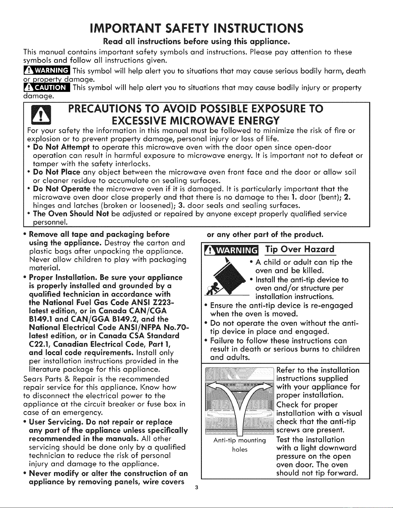
Tip Over Hazard
* A child or adult can tip the
oven and be killed.
* Install the anti-tip device to
oven and/or structure per
installation instructions.
* Ensure the anti-tip device is re-engaged
when the oven is moved.
* Do not operate the oven without the anti-
tip device in place and engaged.
* Failure to follow these instructions can
result in death or serious burns to children
and adults.
Anti-tip mounting
holes
Refer to the installation
instructions supplied
with your appliance for
proper installation.
Check for proper
installation with a visual
check that the anti-tip
screws are present.
Test the installation
with a light downward
pressure on the open
oven door. The oven
should not tip forward.
iMPORTANT SAFETY iNSTRUCTiONS
* Remove the oven door from any unused * Use Only Dry Potholders. Moist or damp
it is to be stored or discarded.
Stepping, leaning or sitting on
is appliance can result in serious
injuries and also cause damage to the unit. Do
not allow children to climb or play around the
unit. The weight of a child on an open door may
cause the appliance to tip, resulting in serious
burns or other injury.
" Protective linersmDo not use aluminum foil
to line the oven bottom. Only use aluminum
foil as recommended in this manual. Improper
installation of these liners may result in risk of
electric shock, or fire.
" Storage in Appliance. Flammable materials
should not be stored near surface units.
This includes paper, plastic and cloth items,
such as cookbooks, plasficware and towels,
as well as flammable liquids. Do not store
explosives, such as aerosol cans, on or near
ce.
Do not use the oven or the
m_crowave oven for storage.
Do not store items of interest to
c e cabinets above an appliance.
Children climbing on the appliance to reach
items could be seriously injured.
* Do not leave children alone. Children should
not be left alone or unattended in the area
where an appffance is in use. They should
never be allowed to sit or stand on any part
of the appliance.
* DO NOT TOUCH HEATING ELEMENTS OR
INTERIOR SURFACES OF OVENS OR ANY
AREAS NEAR THESE ZONE. all oven heating
elements may be hot even though they are
dark in color. Areas near surface zones may
become hot enough to cause burns. During
and after use, do not touch, or let clothing or
other flammable materials touch these areas
until they have had su_icient time to cool.
Among these surfaces near these openings,
oven doors and windows).
* Wear Proper Apparel Loose-fitting or hanging
garments should never be worn while using the
appliance. Do not let clothing or other flammable
materials contact hot surfaces.
Never use your appffance for
warming or heating the room.
* Do Not Use Water or Flour on Grease Fires.
Smother the fire with a pan lid, or use
baking soda, a dry chemical or foam-type
extinguisher.
" When heating fat or grease, watch it closely.
Fat or grease may catch fire if allowed to
become too hot.
potholders on hot surfaces may result in
burns from steam. Do not let the potholders
touch hot heating surface units. Do not use
a towel or other bulky cloth instead of a
potholder.
" Do Not Heat Unopened Food Containers.
Buildup of pressure may cause the container
to burst and result in injury.
IMPORTANTmDo not attempt to operate the
appliance during a power failure. If power
fails, always turn off the appliance. If the
appliance is not turned off: and the power
resumes, it will begin to operate again. Once
the power resumes, reset the clock and oven
function.
IMPORTANT INSTRUCTIONS FOR USING
YOUR MICROWAVE
When using electrical appliances, basic sat ety
precautions should be followed to reduce the risk
of burns, electric shock, fire, injury to persons or
exposure to excessive microwave energy:
* READ ALL instructions before using the appliance.
* Read and follow the specific "PRECAUTIONS
TO AVOID POSSIBLE EXPOSURE TO
EXCESSIVE MICROWAVE ENERGY" on page 3.
*Install or locate this appliance only in
accordance with the provided installation
instructions.
*Some products such as whole eggs and sealed
containers _for example, closed glass jars_
are able to explode and should not be heated
in this microwave oven.
*Use this appliance ONLY for its intended use as
described in this manual. Do not use corrosive
chemicals or vapors in this appliance. This type
of oven is specifically designed to heat, cook
or dry food. It is not designed for industrial or
laboratory use.
*As with any appliance, CLOSE SUPERVISION
is necessary when used by CHILDREN or
INFIRM PERSON.
*This appliance, including power cord, must be
serviced ONLY by qualified service personnel.
Contact nearest Authorized Servicer for
examination, repair or adjustment.
* DO NOT cover or block any openings on the
appliance.
* DO NOT store or use this appliance outdoors.
* DO NOT use this product near water_
for example, near a kitchen sink, in a wet
basement or near a swimming pool, or similar
locations.
* Oversized foods or oversized metal utensils
should NOT be inserted in a microwave oven
iMPORTANT SAFETY
as they may create a fire or risk of electric
shock.
• DO NOT clean with metal scouring pads.
Pieces can burn off the pad and touch
electrical parts involving a risk of electric "
shock.
• DO NOT use paper products when appliance
is operated in the convection or mix mode.
• DO NOT cover racks or any other part of the
microwave oven with metal foil. This will cause
overheating of the oven.
• Review the door cleaning instructions (page 41). •
To reduce the risk of fire in the microwave oven
cavity:
• Do not overcook food. Carefully attend
appliance when paper, plastic or other
combustible materials are placed inside the
microwave oven to facilitate cooking.
• Remove wire twist-ties from paper or plastic
bags before placing bag in microwave oven.
• If materials inside the microwave oven should
ignite, keep microwave oven door closed, ,,
turn microwave oven off and disconnect the
power cord or shut off power at the fuse or
circuit breaker panel. .
• DO NOT use the cavity far storage purposes.
Do not leave paper products, cooking utensils
or food in the cavity when not in use.
Liquids, such as water, coffee or tea are able to
be overheated beyond the boiling point without •
appearing to be boiling. Visible bubbling or
boiling when the container is removed from
the microwave oven is not always present.
THiS COULD RESULT iN VERY HOT LIQUIDS
SUDDENLY BOiLiNG OVER WHEN A SPOON
OR OTHER UTENSIL iS iNSERTED iNTO THE
LiQUiD.
To reduce the risk of injury to persons:
• DO NOT overheat the liquid.
• Stir the liquid both before and halfway through
heating it.
• Do not use straight-sided containers with
narrow necks. Use a wide-mouthed container.
• After heating, allow the container to stand in
the microwave oven at least for 20 seconds
before removing the container.
• Use extreme care when inserting a spoon or
other utensil into the container.
• If the microwave oven light fails, consult a
Sears parts & repair center.
IMPORTANT INSTRUCTIONS FOR USING
YOUR LOWER OVEN
" Use Care When Opening an Oven Door--
iNSTRUCTiONS
Stand to the side of the appliance when
opening the door of a hot oven. Let hot air or
steam escape before you remove or replace
food in the oven.
Keep Oven Vent Ducts Unobstructed. The
wall oven is vented at the upper control panel
or at the center trim depending of the model.
Touching the surfaces in this area when the
wall oven is operating may cause severe
burns. Also, do not place plastic or heat-
sensitive items near the oven vent. These items
could melt or ignite.
Placement of Oven Racks. Always place
oven racks in desired location while oven is
cool. If rack must be moved while oven is hot,
use extreme caution. Use pot holders and
grasp the rack with both hands to reposition.
Do not let pot holders contact the hot oven
element or interior of the oven. Remove all
utensils from the rack before removing rack.
Do not use a broiler pan without its insert.
Broiler pan and grid allow dripping fat to
drain and be kept away from the high heat of
the broiler.
Do not cover the broiler grid or oven bottom
with aluminum foil. Exposed fat and grease
could ignite.
Do not touch a hot oven light bulb with a
damp cloth. Doing so could cause the bulb to
break. Disconnect the appliance or shut off
the power to the appliance before removing
and replacing the bulb.
Do not cook food directly on oven bottom.
Always cook in proper cookware and always
use oven racks.
IMPORTANT INSTRUCTIONS FOR
CLEANING YOUR APPLIANCE
" Clean the appliance regularly to keep all
parts free of grease that could catch fire.
Exhaust fan ventilation hoods and grease filters
should be kept clean. Do not allow grease to
accumulate. Greasy deposits in the fan could
catch fire. Refer to the hood manufacturer's
instructions for cleaning.
Kitchen cleaners and aerosols--Always follow
the manufacturer's recommended directions
for use. Be aware that excess residue from
cleaners and aerosols may ignite causing
damage and injury.
Clean ventilating hoods frequently--Grease
should not be allowed to accumulate on
the hood or filter. Follow manufacturer's
instructions for cleaning.
SELF-CLEANING WALL OVEN MODELS
" Clean in the self-cleaning cycle only the
parts of the appliance listed in this Owner's
Guide. Before using the self-cleaning cycle of
iMPORTANT SAFETY iNSTRUCTiONS
the appliance, remove all utensils stored in the
appliance.
* Do not clean the oven door gasket. The door
gasket is essential for a good seal. Care should
be taken not to rub, damage or move the gasket.
o Do not use oven cleaners. No oven cleaner or
oven liner protective coating of any kind should
be used in or around any part of the appliance
The health of some birds is
extremely sensitive to the fumes given off
during the self-clean cycle of any wall oven.
Move birds to another well ventilated room.
GROUNDING INSTRUCTIONS
Do not use an adapter plug or an extension
cord, or remove grounding prong from the
power cord. Failure to follow this warning
may cause serious injury, fire, or death. For
personal safety, this appliance must be properly
grounded.
For models factory-equipped with a power
FEDERAL COMMUNiCATiONS COMMiSSiON
STATEMENT (U.S.A. ONLY)
cord:
For maximum safety, the power cord must be
plugged into an electrical outlet that is the
correct voltage, is correctly polarized, and is
properly grounded in accordance with local
codes.
For ovens to be wired into a junction box:
It is the personal responsibility of the consumer
to have the appropriate outlet with the correct,
properly grounded wall receptacle installed
by a qualified electrician. See the installation
instructions packaged with this appliance for
complete installation and grounding instructions.
iMPORTANT SAFETY NOTICE
The California Safe Drinking Water and Toxic
Enforcement Act requires the Governor of
California to publish a list of substances known
to the state to cause cancer, birth defects or
other productive harm, and requires businesses
to warn customers of potential exposure to such
substances.
RADIO FREQUENCY iNTERFERENCE
This equipment generates and uses ISM frequency energy and if not installed and used properly,
that is in strict accordance with the manufacturer s instructions, may cause interference to
radio and television reception. It has been type tested and found to comply with limits for ISM
Equipment pursuant to part 18 of FCC Rules, which are designed to provide reasonable protection
against such interference in a residential installation.
However, there is no guarantee that interference will not occur in a particular installation. If this
equipment does cause interference to radio or television reception, which can be determined by
turning the equipment off and on, the user is encouraged to try to correct the interference by one or
more of the following:
* Reorient the receiving antenna of the radio or television.
* Relocate the microwave oven with respect to the receiver.
* Move the microwave oven away from the receiver.
* Hug the microwave oven into a different outlet so that the microwave oven and the receiver are
on different branch circuits.
The manufacturer is not responsible for any radio or television interference caused by
unauthorized modification to this microwave oven. It is the responsibility of the user to correct
such interference.
Product Record
In this space below, record the date of purchase, model and
serial number of your product. You wiii find the model and
serial number printed on the serial plate.
Model No. 790.
Serial No.
Date of purchase
Save these instructions and your sales receipt for future
reference,
Serial Plate Location
You will find the model and serial
number printed on the serial plate.
The serial plate is located along the
interior side trim and visible when
the tower oven door is opened.
Remember to record the serial
number for future reference.
Serial Plate Location
SAVE THESE INSTRUCTIONS FOR FUTURE REFERENCES
6
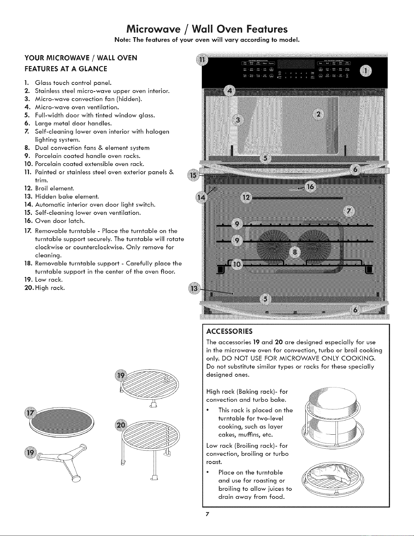
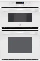
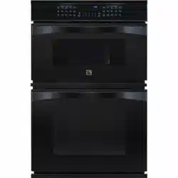
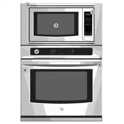
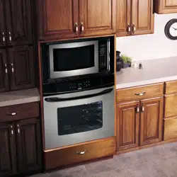
Microwave /Wall Oven Features
Note: The features of your oven will vary according to model.
YOUR MICROWAVE / WALL OVEN
FEATURES AT A GLANCE
1. Glass touch control panel.
2. Stainless steel micro-wave upper oven interior.
3. Micro-wave convection fan (hidden).
4. Micro-wave oven ventilation.
5. Full-width door with tinted window glass.
6. Large metal door handles.
7. Self-cleaning lower oven interior with halogen
lighting system.
8. Dual convection fans & element system
9. Porcelain coated handle oven racks.
10. Porcelain coated extensible oven rack.
11. Painted or stainless steel oven exterior panels &
trim.
12. Broil element.
|3. Hidden bake element.
14. Automatic interior oven door light switch.
15. Self-cleaning lower oven ventilation.
16. Oven door latch.
17. Removable turntable - Place the turntable on the
turntable support securely. The turntable will rotate
clockwise or counterclockwise. Only remove for
cleaning.
18. Removable turntable support - Carefully place the
turntable support in the center of the oven floor.
19. Low rack.
20. High rack.
ACCESSORIES
The accessories 19 and 20 are designed especially for use
in the microwave oven for convection, turbo or broil cooking
only. DO NOT USE FOR MICROWAVE ONLY COOKING.
Do not substitute similar types or racks for these specially
designed ones.
High rack (Baking rack)- for
convection and turbo bake.
This rack is placed on the
turntable for two-level
cooking, such as layer
cakes, mufnns, etc.
Low rack (Broiling rack)- for
convection, broiling or turbo
roast.
Place on the turntable
and use for roasting or
broiling to allow juices to
drain away from food.
7
Microwave Oven important information
RADIO OR TV iNTERFERENCE
Should there be any interference caused by the microwave
oven to your radio or TV, check that the microwave oven
is on a different electrical circuit, relocate the radio or TV
as far away from the microwave oven as feasible or check
position and signal of receiving antenna.
ABOUT YOUR MICROWAVE OVEN
This Use and Care Manual is valuable: read it carefully and
always save it for reference.
A good microwave cookbook is a valuable asset. Check it for
microwave cooking principles, techniques, hints and recipes.
NEVER use the microwave oven without the turntable and
support nor turn the turntable over so that a large dish could
be placed in the microwave oven. The turntable will turn
both clockwise and counterclockwise.
ALWAYS have food in the microwave oven when it is on to
absorb the microwave energy.
When using the microwave oven at power levels below
100%, you may hear the magnetron cycling on and off. It is
normal for the exterior of the microwave oven to be warm
to the touch when cooking or reheating.
Condensation is a normal part of microwave cooking. Room
humidity and the moisture in food will influence the amount
of moisture that condenses in the microwave oven. Generally,
covered foods will not cause as much condensation as
uncovered ones. Ventilation openings must not be blocked.
The microwave oven is for food preparation only. It should
not be used to dry clothes or newspapers.
All microwave ovens are rated by using the IEC Test
Procedure at 1200 watts. In using recipes or package
directions, check food a minute or two before the minimum
time setting elapses and add time accordingly.
ABOUT MICROWAVE COOKING
° Arrange food carefully. Place thickest areas towards outside
of dish.
° Watch cooking time. Cook for the shortest amount of
time indicated and add more as needed. Food severely
overcooked can smoke or ignite.
° Cover foods while cooking. Check recipe or cookbook for
suggestions: paper towels, wax paper, microwave plastic
wrap or a lid. Covers prevent spattering and help foods to
cook evenly.
° Shield with small flat pieces of aluminum foil any thin
areas of meat or poultry to prevent overcooking before
dense, thick areas are cooked thoroughly.
° Stir foods from outside to center of dish once or twice
during cooking, if possible.
° Turn foods over once during microwaving to speed cooking
of such foods as chicken and hamburgers. Large items like
roasts must be turned over at least once.
° Rearrange foods such as meatballs halfway through
cooking both from top to bottom and from the center of
the dish to the outside.
° Use standing time. Always allow food to stand in or out of
the oven after cooking power stops. Standing time after
defrosting or cooking allows the temperature to evenly
spread throughout the food, improving the cooking results.
For inside oven standing time, you can program a "0"
power stage of cooking cycle. See Multiple Stage Cooking.
° Check for doneness. Look for signs indicating that cooking
temperatures have been reached.
Doneness signs include:
- Food steams throughout, not just at edge.
- Center bottom of dish is very hot to the touch.
- Poultry thigh joints move easily.
- Meat and poultry show no pinkness.
- Fish is opaque and flakes easily with a fork.
ABOUT FOODS
* Some products such as whole eggs and sealed
containers--for example, closed jars--will explode and
should not be heated in this microwave oven. Such use of
the microwave oven could result in injury.
* Do not boil eggs in a microwave oven. Pressure will build
up inside egg yolk and will cause it to burst, possibly
resulting in injury.
* Operating the microwave with no food inside for more
than a minute or two may cause damage to the microwave
oven and could start a fire. It increases the heat around the
magnetron and can shorten the life of the microwave oven.
* Foods with unbroken outer "skin" such as potatoes, hot
dogs, sausages, tomatoes, apples, chicken livers and other
giblets, and egg yolks should be pierced to allow steam to
escape during cooking.
* Avoid heating baby food in glass jars, even with the lid
off. Make sure aii infant food is thoroughly cooked. Stir
food to distribute the heat evenly. Be careful to prevent
scalding when warming formula or breast milk. The
container may feel cooler than the milk really is. Always
test the milk before feeding the baby.
* Spontaneous boiling--Under certain special circumstances,
liquids may start to boil during or shortly after removal
from the microwave oven. To prevent burns from splashing
liquid, we recommend the following: before removing the
container from the microwave oven, allow the container
to stand in the microwave oven for 30 to 40 seconds after
the microwave oven has shut off. Do not boil liquids in
narrownecked containers such as soft drink bottles, wine
flasks and especially narrow necked coffee cups. Even if
the container is opened, excessive steam can build up and
cause it to burst or overflow.
* Do not defrost frozen beverages in narrow-necked bottles
(especially carbonated beverages). Even if the container
is opened, pressure can build up. This can cause the
container to burst, possibly resulting in injury.
* Hot foods and steam can cause burns. Be careful when
opening any containers of hot food, including popcorn
bags, cooking pouches and boxes. To prevent possible
injury, direct steam away from hands and face.
* Do not overcook potatoes. They could dehydrate and
catch fire, causing damage to your microwave oven.
* Cook meat and poultry thoroughly--meat to at least an
INTERNAL temperature of 160°F and poultry to at least
an INTERNAL temperature of 170°F Cooking to these
temperatures usually protects against foodborne illness.
Microwave Oven important information (co.t °oedl
ABOUT UTENSILS AND COVERINGS
It is not necessary to buy all new cookware. Many pieces
already in your kitchen can be used successfully in your new
microwave oven. Maize sure the utensil does not touch the
interior walls during cooking.
Use these utensils for safe microwave cooking and
reheating:
° glass ceramic (Pyroceram®), such as Corningware ®
° heat-resistant glass (Pyrex ®)
° microwave-safe plastics
° paper plates
° microwave-safe pottery, stoneware and porcelain
° browning dish (Do not exceed recommended preheating
time. Follow manufacturer's directions.)
These items can be used for short tlme reheating of foods
that have little fat or sugar in them:
° wood, straw, wicker
DO NOT USE
* metal pans and bakeware
* dishes with metallic trim
* non-heat-resistant giass
* non-microwave-safe plastics (margarine tubs)
* recycled paper products
* brown paper bags
* food storage bags
* metal twist-ties
Should you wish to check if a dish is safe for microwaving,
place the empty dish in the microwave oven and microwave
on HIGH for 30 seconds. A dish which becomes very hot
should not be used.
THE FOLLOWING COVERINGS ARE IDEAL:
* Paper towels are good for covering foods for reheating
and absorbing fat while cooking bacon.
* Wax paper can be used for cooking and reheating.
° Plastic wrap that is specially marked for microwave use
can be used for cooking and reheating. DO NOT allow
plastic wrap to touch food. Vent so steam can escape.
° Lids that are microwave-safe are a good choice because
heat is kept near the food to hasten cooking.
° Oven cooking bags are good for large meats or foods that
need tenderizing. DO NOT use metal twist ties. Remember
to slit bag so steam can escape.
HOW TO USE ALUMINUM FOIL IN YOUR
MICROWAVE OVEN:
* Small fiat pieces of aluminum foil placed smoothly on the
food can be used to shield areas that are either defrosting or
cooking too quickly.
° Foil should not come closer than one inch to any surface of
the microwave oven.
Should you have questions about utensils or coverings, check
a good microwave cookbook or follow recipe suggestions.
ACCESSORIES There are many microwave accessories
available for purchase. Evaluate carefully before you
purchase so that they meet your needs. A microwave-safe
thermometer wiii assist you in determining correct doneness
and assure you that foods have been cooked to safe
temperatures. Sears is not responsible for any damage to
the microwave oven when accessories are used.
ABOUT CHILDREN AND THE MICROWAVE
Children below the age of 7 should use the microwave oven
with a supervising person very near to them. Between the
ages of 7 and 12, the supervising person should be in the
same room.
At no time should anyone be allowed to Jean or swing on the
microwave oven door.
Children should be taught all safety precautions: use
potholders, remove coverings carefully, pay special attention
to packages that crisp food because they may be extra hot.
Don't assume that because a child has mastered one
cooking skill he/she can cook everything.
Children need to learn that the microwave oven is not a toy.
ABOUT SAFETY
° Check foods to see that they are cooked to the United
States Department of Agriculture's recommended
temperatures.
160°F For fresh pork, ground meah boneless white
poultry, fish, seafood, egg dishes and frozen
prepared food.
165°F For leftover, ready-to-reheat refrigerated, and
deii and carry-out "fresh" food.
170°F White meat of poultry.
175°F Dark meat of poultry.
To test for doneness, insert a meat thermometer in a
thick or dense area away from fat or bone. NEVER leave
the thermometer in the food during cooking, unless it is
approved for microwave oven use.
° ALWAYS use pothoiders to prevent burns when handling
utensils that are in contact with hot food. Enough heat
from the food can transfer through utensils to cause skin
burns.
° Avoid steam burns by directing steam away from the face
and hands. Slowly lift the farthest edge of a dish's covering
and carefully open popcorn and oven cooking bags away
from the face.
° Stay near the microwave oven while it's in use and check
cooking progress frequently so that there is no chance of
overcooking food.
° NEVER use the cavity for storing cookbooks or other items.
° Select, store and handle food carefully to preserve its high
quality and minimize the spread of foodborne bacteria.
° Keep microwave interior clean. Food residue can cause
arcing and/or fires.
° Use care when removing items from the microwave oven
so that the utensil, your clothes or accessories do not touch
the safety door latches.
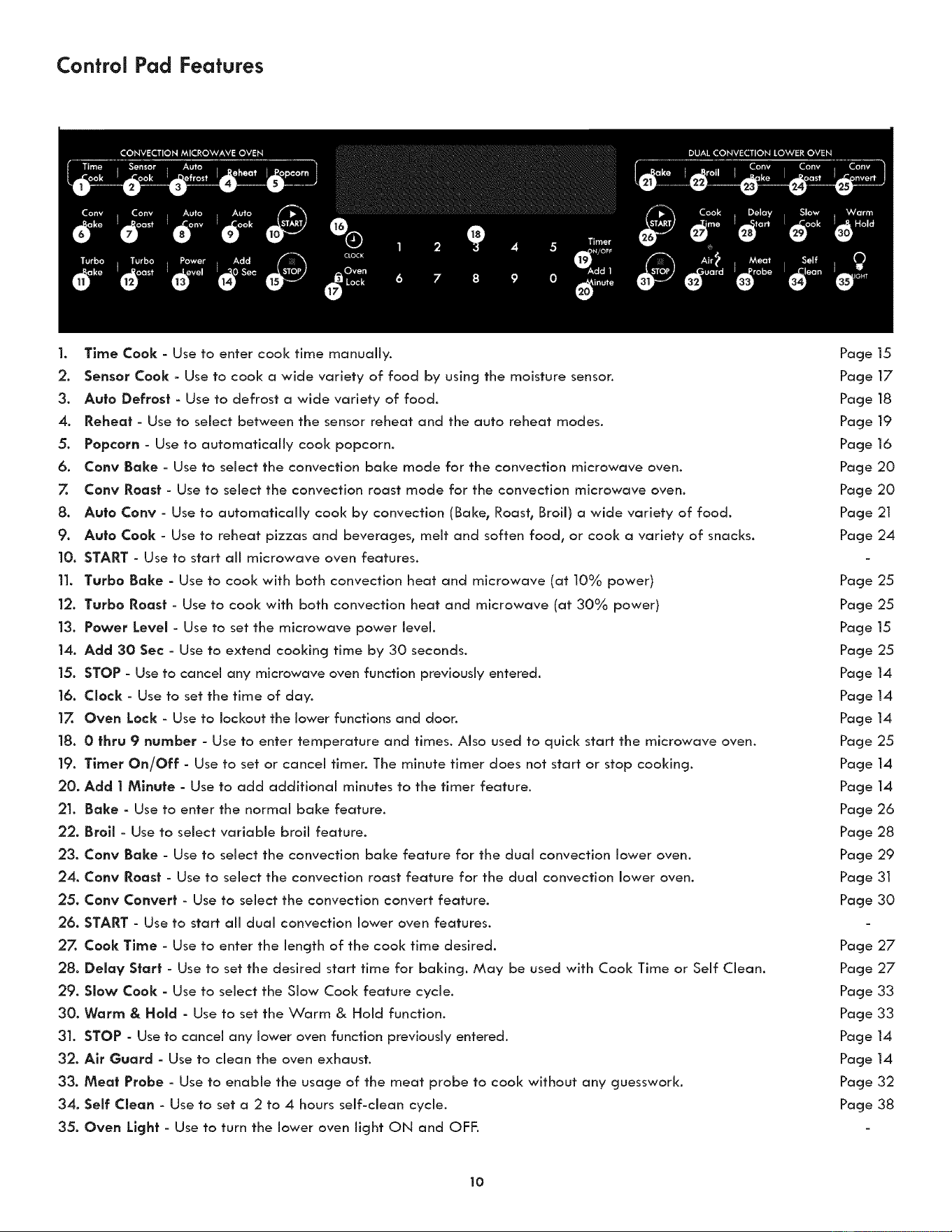
Control Pad Features
1. Time Cook - Use to enter cook time manually.
2. Sensor Cook - Use to cook a wide variety of food by using the moisture senson
3. Auto Defrost - Use to defrost a wide variety of food.
4, Reheat - Use to select between the sensor reheat and the auto reheat modes.
5. Popcorn - Use to automatically cool< popcorn.
6. Cony Bake - Use to select the convection bake mode for the convection microwave oven.
7. Cony Roast - Use to select the convection roast mode for the convection microwave oven.
8. Auto Cony - Use to automatically cook by convection (Bake, Roast, Broil) a wide variety of food.
9. Auto Cook - Use to reheat pizzas and beverages, melt and soften food, or cook a variety of snacks.
10. START - Use to start all microwave oven features.
11. Turbo Bake - Use to cool< with both convection heat and microwave (at 10% power)
12. Turbo Roast - Use to cook with both convection heat and microwave (at 30% power)
13. Power Level - Use to set the microwave power level.
14. Add 30 Sec- Use to extend cooking time by 30 seconds.
15. STOP - Use to cancel any microwave oven function previously entered.
16. Clock - Use to set the time of day.
17. Oven Lock - Use to lockout the lower functions and door.
18. 0 thru 9 number - Use to enter temperature and times. Also used to quick start the microwave oven.
19. Timer On/Off - Use to set or cancel timer. The minute timer does not start or stop cooking,
20. Add 1 Minute - Use to add additional minutes to the timer feature.
21, Bake - Use to enter the normal bake feature.
22. Broil - Use to select variable broil feature.
23. Cony Bake - Use to select the convection bake feature for the dual convection lower oven.
24. Cony Roast - Use to select the convection roast feature for the dual convection lower oven.
25. Cony Convert - Use to select the convection convert feature.
26. START - Use to start all dual convection lower oven features.
27. Cook Time - Use to enter the length of the cook time desired.
28. Delay S|art - Use to set the desired start time for baking. May be used with Cook Time or Self Clean.
29. Slow Cook - Use to select the Slow Cook feature cycle.
30. Warm & Hold - Use to set the Warm & Hold function.
31. STOP - Use to cancel any lower oven function previously entered,
32. Air Guard - Use to clean the oven exhaust.
33. Meat Probe - Use to enable the usage of the meat probe to cook without any guesswork,
34. Self Clean - Use to set a 2 to 4 hours self-clean cycle.
35. Oven Light - Use to turn the lower oven light ON and OFF,
Page 15
Page 17
Page 18
Page 19
Page 16
Page 20
Page 20
Page 21
Page 24
Page 25
Page 25
Page 15
Page 25
Page 14
Page 14
Page 14
Page 25
Page 14
Page 14
Page 26
Page 28
Page 29
Page 3I
Page 30
Page 27
Page 27
Page 33
Page 33
Page 14
Page 14
Page 32
Page 38
10
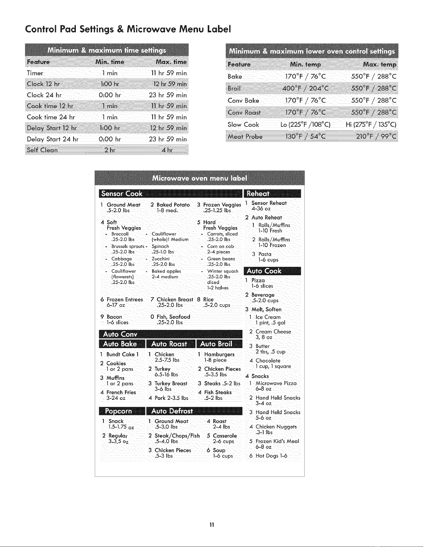
Control Pad Settings & Microwave Menu Label
CloCk 24 hr 0100 hr 23hr59min
Bake t700F _ 760C 550°F/2880C
o o o 0
Cony Bake 170 F / 76 C 550 F / 288 C
Delay Start 24 hr 0:00 hr 23 hr 59 min
o o . o o
SOW Cook Lo(225F/108 C) H,(275F/ 135C)
1 Ground Meat 2 Baked Potato 3 Frozen Veggies
.5-2.0 bs 1-8 med. .25-1.25 Ibs
4 Soft 5 Hard
Fresh Veggies Fresh Veggies
Broccoli - Cauliflower ......... sliced
.25-2.0 Ibs (whole)l Medium ,25-2.0 Ibs
- Brussels sprouts- Spinach - Corn on cob
.25-2.0 Ibs .25-I,0 Ibs 2-4 pieces
- Cabbage - Zucchini - Green beans
.25-2.0 Ibs ,25-2.0 Ibs .25-2.0 Ibs
Cauliflower
(flowerets)
.25-2.0 Ibs
6 Frozen Entrees
6-17 oz
9 Bacon
1-6 siices
1 Sensor Reheat
4-36 oz
2 Auto Reheat
1 Rolls/Muffins
1-10 Fresh
2 Rolls/Muffins
1-10 Frozen
3 Pasta
1-6 cups
Baked apples '¢Vintersquash
2-4 medium .25-2.0 Ibs
diced 1 Pizza
1-2halves 1-6 slices
2 Beverage
7 Chicken Breast 8 Rice .5-2.0 cups
.25-2.0 Ibs .5-2.0 cups
3 MeNt, Soften
0 Fish, Seafood 1 Ice Cream
.25-2.0 bs 1 pint, .5 gal
1 BundtCakel 1 Chicken 1 Hamburgers
2.5-Z5 Ibs 1-8 piece
2 Cookies
1 or 2 pans 2 Turkey 2 Chicken Pieces
3 Muffins 6.5=16 ibs .5-3.5 Ibs
1 or 2 pans 3 Turkey Breast 3 Steaks .5-2 Ibs
3-6 Ibs
4 French Fries 4 Fish Steaks
3-24 oz 4 Pork 2-3.5 Ibs .5-2 Ibs
I Snack ] Ground Meat 4 Roast
1.5-1.75 oz .5-3.0 Ibs 2-4 Ibs
2 Regular 2 Steak/Chops/Fish 5 Casserole
3=3.5 oz .5-4.0 Ibs 2-6 cups
3 Chicken Pieces
.5-3 Ibs
2 Cream Cheese
3,8 oz
3 Butter
2 tbs, .5 cup
4 Chocolate
1 cup, 1 square
4 Snacks
I Microwave Pizza
6-8 oz
2 Hand Held Snacks
3-4 oz
3 Hand Held Snacks
5-6 oz
4 Chicken Nuggets
.3-1 Ibs
5 Frozen Kid's Meal
6-8 oz
6 Soup
1-6 cups 6 Hot Dogs I-6
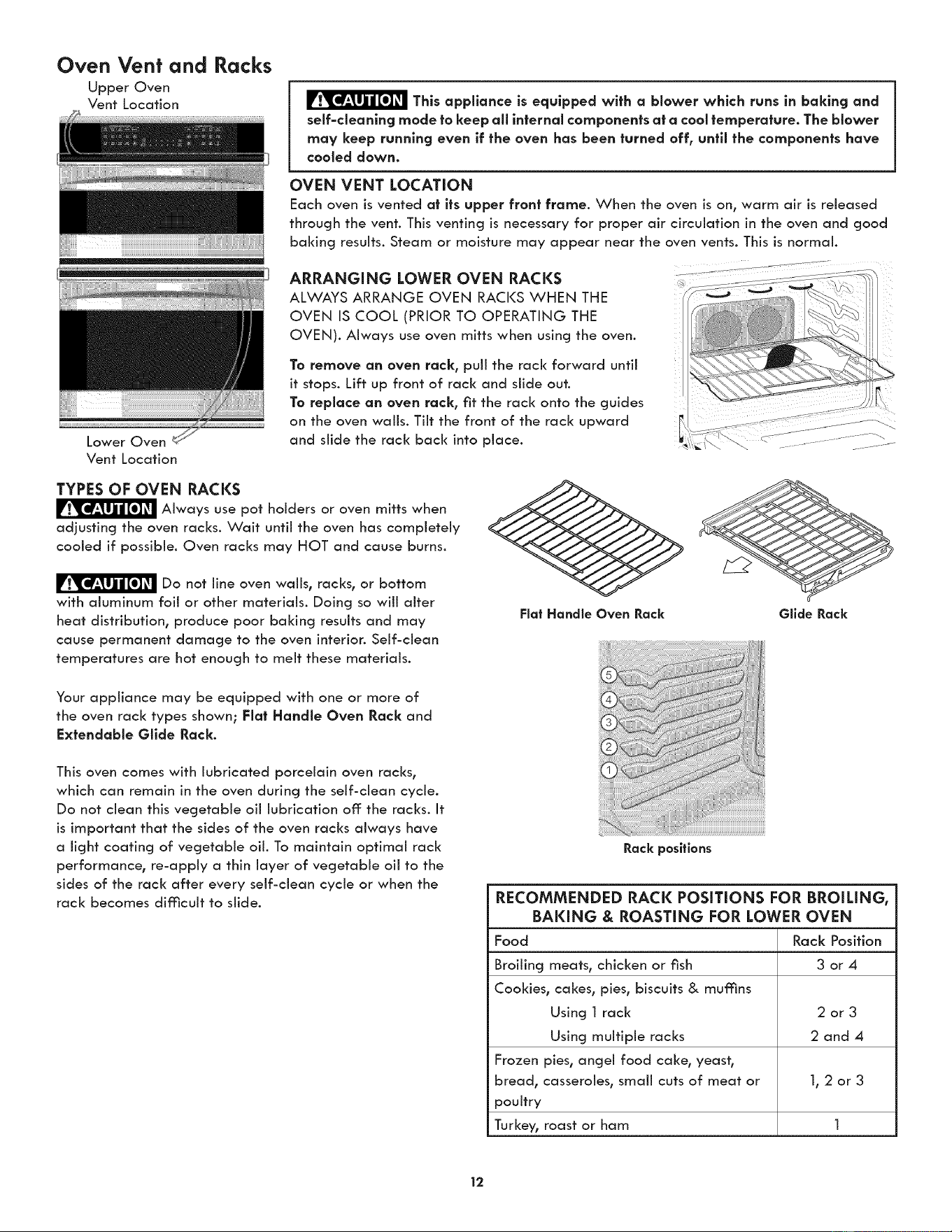
Oven Vent and
Upper Oven
Vent Location
Lower Oven
Vent Location
Racks
This appliance is equipped with a blower which runs in baking and
self=cleanlng mode to keep all internal components at a cool temperature. The blower
may keep running even if the oven has been turned off, until the components have
cooled down.
OVEN VENT LOCATION
Each oven is vented at its upper front frame. When the oven is on, warm air is released
through the vent. This venting is necessary for proper air circulation in the oven and good
baking results. Steam or moisture may appear near the oven vents. This is normal.
ARRANGING LOWER OVEN RACKS ...................
ALWAYS ARRANGE OVEN RACKS WHEN THE
OVEN IS COOL (PRIOR TO OPERATING THE
OVEN). Always use oven mitts when using the oven.
To remove an oven rack, puii the rack forward until
it stops. Lift up front of rack and slide out.
To replace an oven rack, fit the rack onto the guides
on the oven wails. Tilt the front of the rack upward
and slide the rack back into place.
TYPES OF OVEN RACKS
Always use pot holders or oven mitts when
adjusting the oven racks. Wait until the oven has completely
cooled if possible. Oven racks may HOT and cause burns.
Do not line oven wails, racks, or bottom
with aluminum foil or other materials. Doing so wiii alter
heat distribution, produce poor baking results and may
cause permanent damage to the oven interior. Self-clean
temperatures are hot enough to melt these materials.
Your appliance may be equipped with one or more of
the oven rack types shown; Flat Handle Oven Rack and
Extendable Glide Rack.
This oven comes with lubricated porcelain oven racks,
which can remain in the oven during the self-dean cycle.
Do not clean this vegetable oil lubrication off: the racks. It
is important that the sides of the oven racks always have
a light coating of vegetable oil. To maintain optimal rack
performance, re-apply a thin layer of vegetable oil to the
sides of the rack after every self-dean cycle or when the
rack becomes difficult to slide.
Rack positions
RECOMMENDED RACK POSiTiONS FOR BROILING,
BAKING & ROASTING FOR LOWER OVEN
Food Rack Position
Broiling meats, chicken or fish 3 or 4
Cookies, cakes, pies, biscuits & muffins
Using 1 rack 2 or 3
Using multiple racks 2 and 4
Frozen pies, angel food cake, yeast,
bread, casseroles, small cuts of meat or 1, 2 or 3
poultry
Turkey, roast or ham 1
12
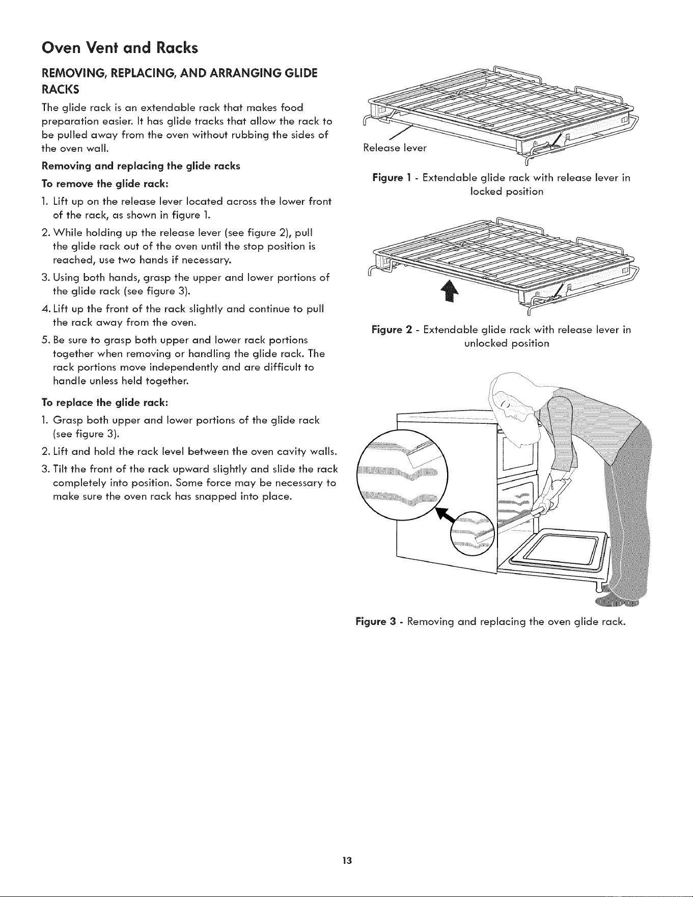
Oven Vent and Racks
REMOVING, REPLACING, AND ARRANGING GLIDE
RACKS
The glide rack is an extendable rack that maizes food
preparation easier. It has glide tracks that allow the rack to
be pulled away from the oven without rubbing the sides of
the oven wall.
Removing and replacing the gllde racks
To remove the glide rack:
1. Lift up on the release lever located across the lower front
of the rack° as shown in figure 1.
2. While holding up the release lever (see figure 2), puii
the glide rack out of the oven until the stop position is
reached, use two hands if necessary.
3. Using both hands, grasp the upper and lower portions of
the glide rack (see figure 3).
4. Lift up the front of the rack slightly and continue to puil
the rack away from the oven.
5. Be sure to grasp both upper and lower rack portions
together when removing or handling the glide rack. The
rack portions move independently and are difficult to
handle unless held together.
To replace the gllde rack:
1. Grasp both upper and lower portions of the glide rack
(see figure 3).
2. Lift and hold the rack level between the oven cavity walls.
3. Tilt the front of the rack upward slightly and slide the rack
completely into position. Some force may be necessary to
maize sure the oven rack has snapped into place.
Figure I - Extendable glide rack with release lever in
locked position
Figure 2 - Extendable glide rack with release lever in
unlocked position
Figure 3 - Removing and replacing the oven glide rack.
13
Getting Started
SETTING CLOCK AT POWER UP
You will be prompted to enter the time of day in the event
of a power failure or when you first provide electric power
to your appliance.
° When your appliance is first powered up, 12:00 will flash
in the display.
* Enter the time of day using the numeric key pads and
press START to set.
If an invalid time of day is entered, the control wiii triple
beep. Re-enter a valid time of day and press START. If
STOP is pressed your clock will start with the time set for
12:00.
Select the CLOCK @ key to modify the time of day during
other situations such as day light savings.
TIMER
The timer provided with the oven control serves as an extra
reminder in the kitchen. When the timer reaches less than 1
minute the display will start to count down in seconds. When
the time runs out the active timer will beep, and "End" will be
displayed.
The following time settings apply to the timer:
° Min. time: 1 minute
° Max. time: 11hours 59 minutes
See example below to set the timer for 5 minutes:
1. Press TIMER ON/OFF
2. Enter 5 minutes
3. Press START
To cancel or end the timer, press the TIMER SET/OFF key
again.
NOTE: The timer(s) will not affect the cooking process.
TO SET ADD 1 MINUTE FEATURE
The ADD 1 MINUTE pad is used to set the Add 1 Minute
feature. When the pad is pressed, 1 minute is added to the
Timer feature if this feature is already active. If the Timer
feature is not active and the pad is pressed, the Timer
feature will become active and will begin counting down
from 1 minute. For further information on how to set the
Timer feature see Timer instructions above.
PREHEAT TEMPERATURE DISPLAY
Once a cooking feature has been started in one of the
ovens, the control will display the actual oven temperature
while preheating. Once the oven reaches the oven set
temperature only the oven set temperature will display.
The preheat temperature display is available with the
following cooking modes:
* Bake in lower oven
° Cony Bake in both ovens
SETTING OVEN LOCI(
The Oven Loci< feature automatically locks the oven door
and prevents the oven from being turned on. It does not
disable the clock, Timer or the interior oven lights.
See example below to lock the oven.
To loci<, press and hold OVEN LOCK for 3 seconds.
To unlock, press and hold OVEN LOCK for 3 seconds.
DOOR LOCKED will flash in the display until the door has
finished locking. Once the door has been locked the door
loci< indicator will turn on. DOOR LOCKED will then stay
displayed.
Do not attempt to open the oven door while the door loci<
indicator is flashing.
OPERATING OVEN LIGHTS
The interior oven lights wiil automatically turn on when the
oven door is opened. The oven light will not operate during
a self clean cycle. Press 9 to turn the interior oven lights on
and off whenever the oven door is closed. The interior oven
lights are located on the rear wail of the oven interior and
are covered with a glass shield. The glass shield protects the
bulb from high temperatures and should always be in place
whenever the oven is in use.
iMPORTANT: For best baking results, do not leave oven light
on while cooking.
USING THE AIRGUARD FEATURE
Your appliance is equipped with a catalytic oven exhaust
cleaner that may be turned on during any cooking process.
This feature helps remove smoke and eliminates 85% of
the odors generated when using your oven. DO NOT use
AirGuard when baking delicate bakery items.
If you wish to clean the oven exhaust once cooking has
started, press AIRGUARD.
NOTE: The AirGuard indicator light will glow anytime
AirGuard is active. AirGuard will automatically turn on and
cannot be manually turned off during the Self-Cleaning
cycle.
14
Microwave Manual Operation
TIME COOKING
Your Microwave Oven can be programmed up to 99
minutes 59 seconds (99.59). Always enter the seconds after
the minutes, even if they are both zeros.
° Suppose you want to cool< for 5 minutes at 100%.
1. Press TUME COOK
2. Enter cooking time by pressing 5 0 0 on the numeric
pads.
3. Press START
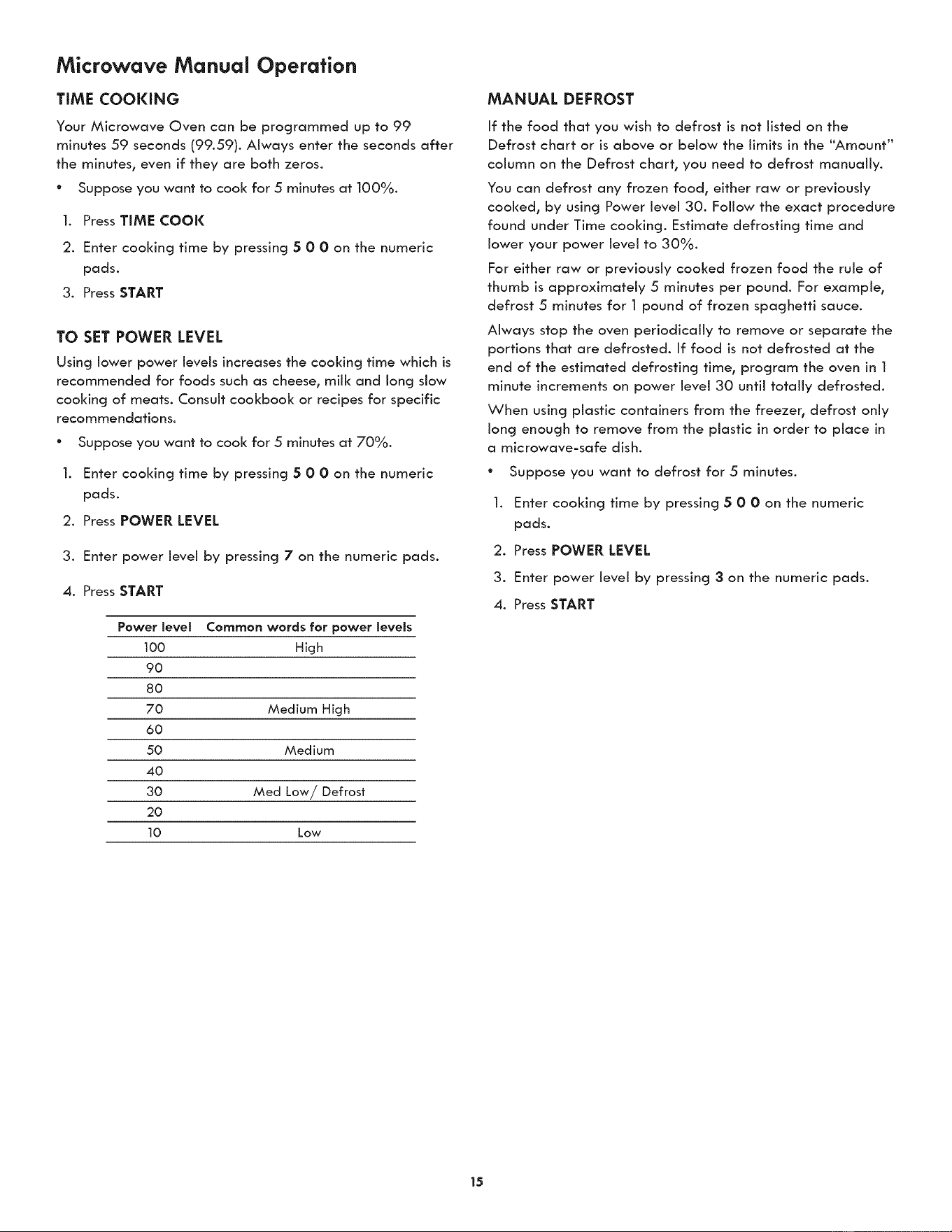
TO SET POWER LEVEL
Using lower power levels increases the cooking time which is
recommended for foods such as cheese, mill< and long slow
cooking of meats. Consult cookbook or recipes for specific
recommendations.
e
].
Suppose you want to cool< for 5 minutes at 70%.
Enter cooking time by pressing 5 0 0 on the numeric
pads.
2. Press POWER LEVEL
3. Enter power level by pressing 7 on the numeric pads.
4. Press START
Power level Common words for power levels
100 High
9O
8O
70 Medium High
6O
50 Medium
40
30 Med Low/Defrost
2O
10 Low
MANUAL DEFROST
If the food that you wish to defrost is not listed on the
Defrost chart or is above or below the limits in the "Amount"
column on the Defrost chart, you need to defrost manually.
You can defrost any frozen food, either raw or previously
cooked, by using Power level 30. Follow the exact procedure
found under Time cooking. Estimate defrosting time and
lower your power level to 30%.
For either raw or previously cooked frozen food the rule of
thumb is approximately 5 minutes per pound. For example,
defrost 5 minutes for 1 pound of frozen spaghetti sauce.
Always stop the oven periodically to remove or separate the
portions that are defrosted. If food is not defrosted at the
end of the estimated defrosting time, program the oven in 1
minute increments on power level 30 until totally defrosted.
When using plastic containers from the freezer, defrost only
long enough to remove from the plastic in order to place in
a microwave-safe dish.
* Suppose you want to defrost for 5 minutes.
1. Enter cooking time by pressing 5 0 0 on the numeric
pads.
2. Press POWER LEVEL
3. Enter power level by pressing 3 on the numeric pads.
4. Press START
15
Microwave Operating Instructions
SENSOR MODE
The sensor is a semi-conductor device that detects the vapor
(moisture and humidity) emitted from the food as it heats.
The sensor adjusts the cooking times and power level for
various foods and quantities. Popcorn, Sensor Cook and
Sensor Reheat are part of the Sensor Mode.
Using Sensor Mode:
1. After oven is plugged in, wait 2 minutes before using
Sensor Mode.
.
.
4.
.
6.
Be sure the exterior of the cooking container and the
interior of the oven are dry. Wipe off any moisture with
a dry cloth or paper towel.
The oven works with foods at normal storage
temperature. For example, popcorn would be at room
temperature.
Any Sensor Mode selection can be programmed with
more or less time adjustment.
More or less food than the quantity listed in the chart
should be cooked following the guidelines in any
microwave cookbook.
During the first part of any sensor cooking or reheating,
SENSING will appear on the display. Do not open the
oven door during this part of the cycle. The measurement
of vapor will be interrupted. If this occurs, an error
message will appear. To continue cooking, press the
STOP pad and cook manually.
When the sensor detects the vapor emitted from the
food, remainder of cooking time will appean Door may
be opened when remaining cooking time appears on
the display. At this time, you may stir or season food, as
desired.
7. Except for popcorn, if the sensor does not detect vapor
properly when cooking other foods, ERROR will be
displayed.
8. Check food for temperature after cooking. If additional
time is needed, continue to cook manually.
POPCORN
You can cool< popcorn by touching a quick pad (popcorn).
You don't need to calculate cooking time or power level.
° Suppose you want to pop a 3.5 oz. bag of popcorn.
1. Press POPCORN.
2. Press 2 for regular size.
3. Press START
Amount
1. Snack 1.5-1.75 oz bag
2. Regular 3.0 - 3.5 oz bag
Procedure
Use only popcorn packaged for the microwave. Try
several brands to decide which you like. After popping
cycle do not try to reheat unpopped kernels. This sensor
works weii with most brands of microwave popcorn. You
may wish to try several and choose your favorite. Pop
only one bag at a time. Unfold the bag and place in oven
according to directions.
NOTES
The final result wiii vary according to the food condition
(e.g. initial temperature, shape, quality). Check food for
temperature after heating. If additional time is needed,
continue to heat manually.
This mode can be programmed with More or less time
adjustment by touching the power level pad once or twice
before touching START pad.
COVERING FOODS
Some foods cook better when covered. Use the cover
recommended in the food charts.
1. Casserole lid.
.
.
Plastic wrap: Use plastic wrap recommended for
microwave cooking. Cover dish loosely; allow
approximately 1/2 inch to remain uncovered to allow
steam to escape. Plastic wrap should not touch food.
Wax paper: Cover dish completely; fold excess wrap
under dish to secure. If dish is wider than paper, overlap
two pieces at least one inch to cover.
Be careful when removing any covering to allow steam to
escape away from you.
16
Microwave Operating Instructions (continued)
SENSOR COOl(
You can cool< many foods by touching the sensor cook pad
and the food number. You don't need to calculate cooking
time or power level.
Suppose you want to cool< a baked potato.
I. Press SENSOR COOK
2. Press 2 for baked potato.
3. Press START
NOTES
1. The final result will vary according to the food
condition (e.g. initial temperature, shape, quality).
Check food for temperature after heating. If
additional time is needed, continue to heat manually.
2. Stay near the oven while it's in use and check
cooking progress frequently so that there is no
chance of overcooking food.
3. This mode can be programmed with more or less time
adjustment by touching the power level pad once or
twice before touching START pad.
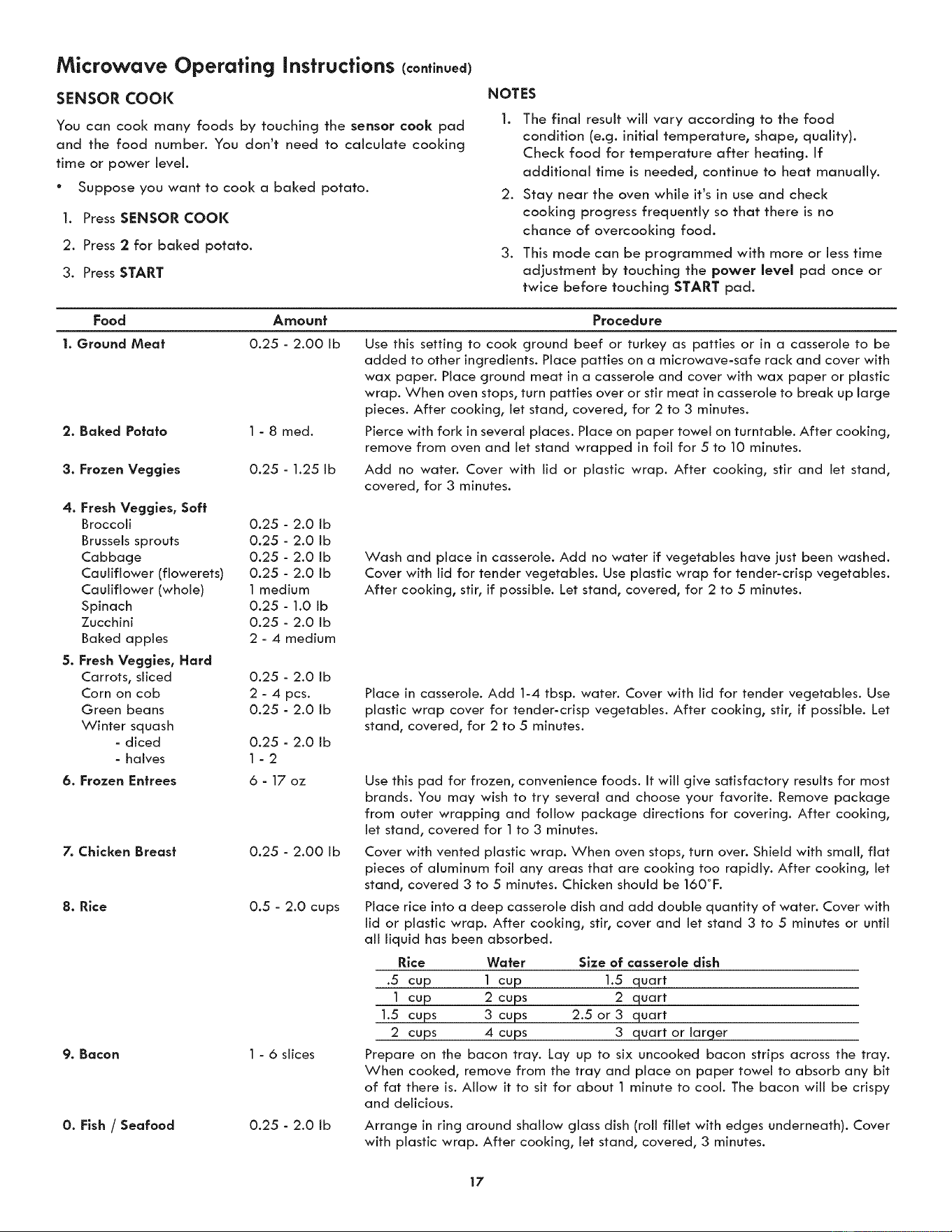
Food Amount Procedure
1. Ground Meat 0.25 - 2.00 Ib
1 - 8 med.
0.25 - 1.25 Ib
4. Fresh Veggles, Soft
Broccoli 0.25 - 2.0 Ib
Brussels sprouts 0.25 - 2.0 Ib
Cabbage 0.25 - 2.0 Ib
Cauliflower (flowerets) 0.25 - 2.0 Ib
Cauliflower (whole) 1 medium
Spinach 0.25 - 1.0 Ib
Zucchini 0.25 - 2.0 Ib
Baked apples 2 - 4 medium
5, Fresh Veggles, Hard
Carrots, sliced 0.25 - 2.0 Ib
Corn on cob 2 - 4 pcs.
Green beans 0.25 - 2.0 Ib
Winter squash
- diced 0.25 - 2.0 Ib
- halves 1 - 2
6. Frozen Entrees 6 - 17 oz
7. Chicken Breast 0.25 - 2.00 Ib
8. Rice 0.5 - 2.0 cups
9. Bacon 1 - 6 slices
0. Fish / Seafood
0.25 - 2.0 Ib
Use this setting to cook ground beef or turkey as patties or in a casserole to be
added to other ingredients. Place patties on a microwave-safe rack and cover with
wax paper. Place ground meat in a casserole and cover with wax paper or plastic
wrap. When oven stops, turn patties over or stir meat in casserole to break up large
pieces. After cooking, let stand, covered, for 2 to 3 minutes.
Pierce with fork in several places. Place on paper towel on turntable. After cooking,
remove from oven and let stand wrapped in foil for 5 to 10 minutes.
Add no water. Cover with lid or plastic wrap. After cooking, stir and let stand,
covered, for 3 minutes.
Wash and place in casserole. Add no water if vegetables have just been washed.
Cover with lid for tender vegetables. Use plastic wrap for tender-crisp vegetables.
After cooking, stir, if possible. Let stand, covered, for 2 to 5 minutes.
Place in casserole. Add 1-4 tbsp. water. Cover with lid for tender vegetables. Use
plastic wrap cover for tender-crisp vegetables. After cooking, stir, if possible. Let
stand, covered, for 2 to 5 minutes.
Use this pad for frozen, convenience foods. It will give satisfactory results for most
brands. You may wish to try several and choose your favorite. Remove package
from outer wrapping and follow package directions for covering. After cooking,
let stand, covered for 1 to 3 minutes.
Cover with vented plastic wrap. When oven stops, turn over. Shield with small, flat
pieces of aluminum foil any areas that are cooking too rapidly. After cooking, let
stand, covered 3 to 5 minutes. Chicken should be 160°F.
Place rice into a deep casserole dish and add double quantity of water. Cover with
lid or plastic wrap. After cooking, stir, cover and let stand 3 to 5 minutes or until
all liquid has been absorbed.
Rice Water Size of casserole dish
.5 cup 1 cup 1.5 quart
1 cup 2 cups 2 quart
1.5 cups 3 cups 2.5 or 3 quart
2 cups 4 cups 3 quart or larger
Prepare on the bacon tray. Lay up to six uncooked bacon strips across the tray.
When cooked, remove from the tray and place on paper towel to absorb any bit
of fat there is. Allow it to sit for about 1 minute to cool. The bacon will be crispy
and delicious.
Arrange in ring around shallow glass dish (roll fillet with edges underneath). Cover
with plastic wrap. After cooking, let stand, covered, 3 minutes.
17
Microwave Operating Instructions (continued)
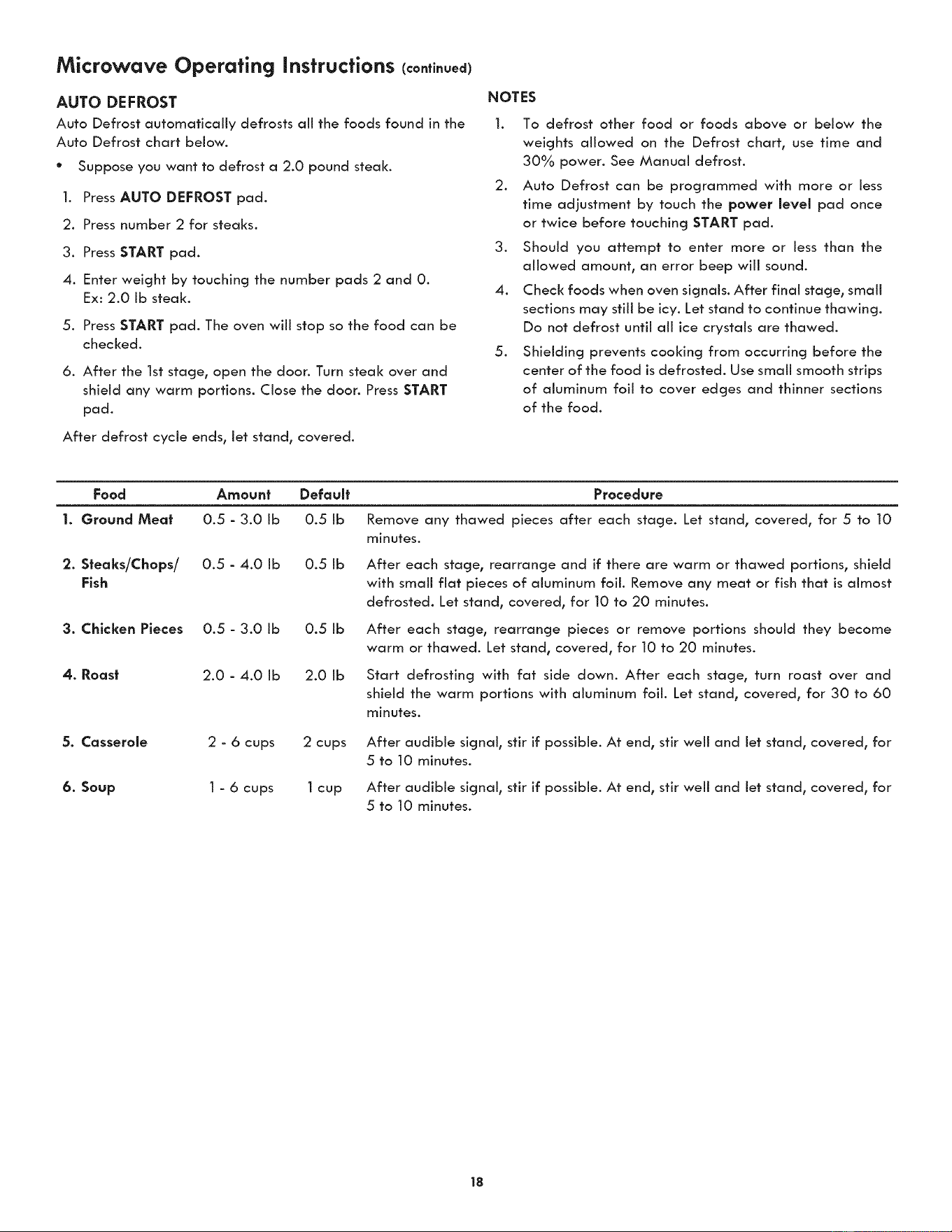
AUTO DEFROST
Auto Defrost automatically defrosts all the foods found in the
Auto Defrost chart below.
Suppose you want to defrost a 2.0 pound steal<.
@
1.
Press AUTO DEFROST pad.
2. Press number 2 for steaks.
3. Press START pad.
4. Enter weight by touching the number pads 2 and 0.
Ex: 2.0 Ib steak.
5. Press START pad. The oven wiii stop so the food can be
checked.
6. After the 1st stage, open the door. Turn steak over and
shield any warm portions. Close the door. Press START
pad.
After defrost cycle ends, let stand, covered.
NOTES
1. To defrost other food or foods above or below the
weights allowed on the Defrost chart, use time and
30% power. See Manual defrost.
2. Auto Defrost can be programmed with more or less
time adjustment by touch the power level pad once
or twice before touching START pad.
3. Should you attempt to enter more or less than the
allowed amount, an error beep will sound.
4. Check foods when oven signals. After final stage, small
sections may still be icy. Let stand to continue thawing.
Do not defrost until all ice crystals are thawed.
5. Shielding prevents cooking from occurring before the
center of the food is defrosted. Use small smooth strips
of aluminum foil to cover edges and thinner sections
of the food.
Food Amount Default
1. Ground Mea| 0.5 - 3.0 Ib 0.5 Ib
2. Steaks/Chops/ 0.5 - 4.0 Ib 0.5 Ib
Fish
3. Chicken Pieces 0.5 - 3.0 Ib 0.5 Ib
4. Roast 2.0 - 4.0 Ib 2.0 Ib
5. Casserole 2 - 6 cups 2 cups
6. Soup 1 - 6 cups 1 cup
Procedure
Remove any thawed pieces after each stage. Let stand, covered, for 5 to 10
minutes.
After each stage, rearrange and if there are warm or thawed portions, shield
with small fiat pieces of aluminum foil. Remove any meat or fish that is almost
defrosted. Let stand, covered, for 10 to 20 minutes.
After each stage, rearrange pieces or remove portions should they become
warm or thawed. Let stand, covered, for 10 to 20 minutes.
Start defrosting with fat side down. After each stage, turn roast over and
shield the warm portions with aluminum foil. Let stand, covered, for 30 to 60
minutes.
After audible signal, stir if possible. At end, stir weii and let stand, covered, for
5 to 10 minutes.
After audible signal, stir if possible. At end, stir weii and let stand, covered, for
5 to 10 minutes.
18
Microwave Operating Instructions (continued)
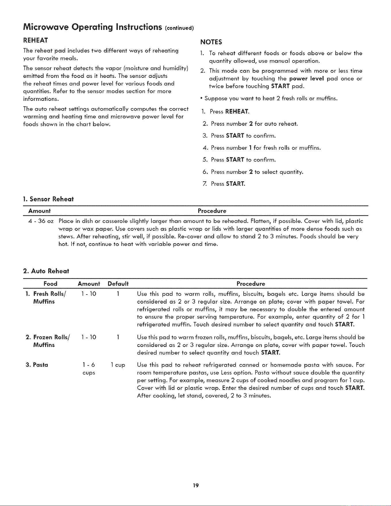
REHEAT
The reheat pad includes two different ways of reheating
your favorite meals.
The sensor reheat detects the vapor (moisture and humidity)
emitted from the food as it heats. The sensor adjusts
the reheat times and power level for various foods and
quantities. Refer to the sensor modes section for more
informations.
The auto reheat settings automatically computes the correct
warming and heating time and microwave power level for
foods shown in the chart below.
NOTES
1. To reheat different foods or foods above or below the
quantity allowed, use manual operation.
2. This mode can be programmed with more or less time
adjustment by touching the power level pad once or
twice before touching START pad.
° Suppose you want to heat 2 fresh rolls or muffins.
1. Press REHEAT.
2. Press number 2 for auto reheat.
3. Press START to confirm.
4. Press number | for fresh rolls or muffins.
5. Press START to confirm.
6. Press number 2 to select quantity.
7. Press START.
1. Sensor Rehea_
Amount Procedure
4 - 36 oz
Place in dish or casserole slightly larger than amount to be reheated. Flatten, if possible. Cover with lid, plastic
wrap or wax paper. Use covers such as plastic wrap or lids with larger quantities of more dense foods such as
stews. After reheating, stir well, if possible. Re-cover and allow to stand 2 to 3 minutes. Foods should be very
hot. If not, continue to heat with variable power and time.
2. Auto Rehea_
Food Amount Default
1. Fresh Rolls/ 1 - 10 1
Muffins
2. Frozen Rolls/ 1 - 10
Muffins
3. Pasta 1 - 6 1 cup
cups
Procedure
Use this pad to warm roils, muffins, biscuits, bagels etc. Large items should be
considered as 2 or 3 regular size. Arrange on plate; cover with paper towel. For
refrigerated rolls or muffins, it may be necessary to double the entered amount
to ensure the proper serving temperature. For example, enter quantity of 2 for 1
refrigerated muffin. Touch desired number to select quantity and touch START.
Use this pad to warm frozen rolls, muffins, biscuits, bagels, etc. Large items should be
considered as 2 or 3 regular size. Arrange on plate, cover with paper towel. Touch
desired number to select quantity and touch START.
Use this pad to reheat refrigerated canned or homemade pasta with sauce. For
room temperature pastas, use Less option. Pasta without sauce double the quantity
per setting. For example, measure 2 cups of cooked noodles and program for 1 cup.
Cover with lid or plastic wrap. Enter the desired number of cups and touch START.
After cooking, let stand, covered, 2 to 3 minutes.
19
Microwave Operating Instructions (continued)
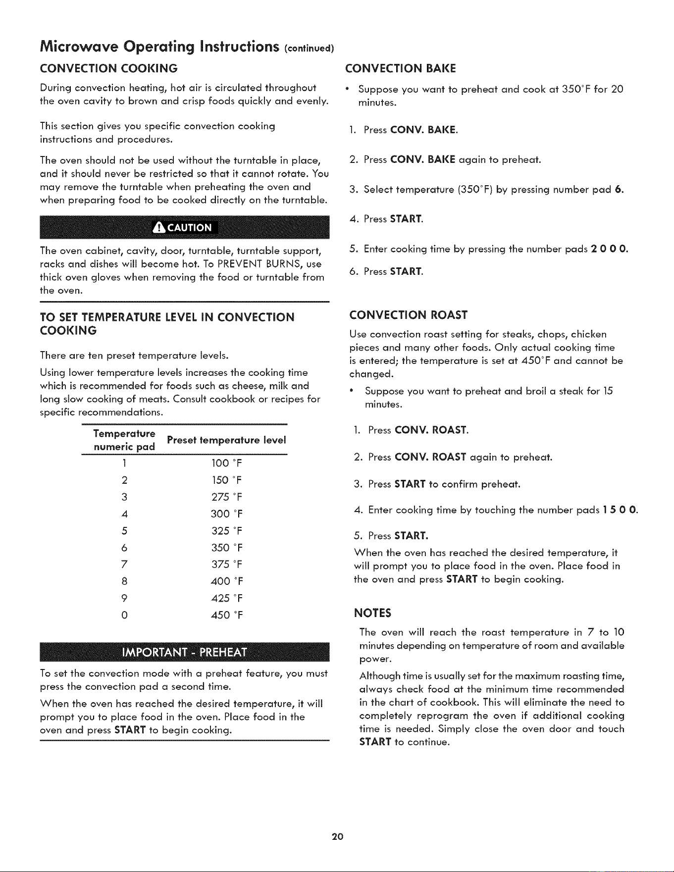
CONVECTION COOKING
During convection heating, hot air is circulated throughout
the oven cavity to brown and crisp foods quickly and evenly.
This section gives you specific convection cooking
instructions and procedures.
The oven should not be used without the turntable in place,
and it should never be restricted so that it cannot rotate. You
may remove the turntable when preheating the oven and
when preparing food to be cooked directly on the turntable.
The oven cabinet, cavity, door, turntable, turntable support,
racks and dishes will become hot. To PREVENT BURNS, use
thick oven gloves when removing the food or turntable from
the oven.
TO SET TEMPERATURE LEVEL IN CONVECTION
COOKING
There are ten preset temperature levels.
Using lower temperature levels increases the cooking time
which is recommended for foods such as cheese, milk and
long slow cooking of meats. Consult cookbook or recipes for
specific recommendations.
Temperature Preset temperature level
numeric pad
1 100 °F
2 150 °F
3 275 °F
4 300 °F
5 325 °F
6 350 °F
7 375 °F
8 400 °F
9 425 oF
0 450 °F
To set the convection mode with a preheat feature, you must
press the convection pad a second time.
When the oven has reached the desired temperature, it will
prompt you to place food in the oven. Place food in the
oven and press START to begin cooking.
CONVECTION BAKE
* Suppose you want to preheat and cool< at 350°F for 20
minutes.
1. Press CONV. BAKE.
2. Press CONV. BAKE again to preheat.
3. Select temperature (350°F) by pressing number pad 6.
4. Press START.
5. Enter cooking time by pressing the number pads 2 0 00.
6. Press START.
CONVECTION ROAST
Use convection roast setting for steaks, chops, chicken
pieces and many other foods. Only actual cooking time
is entered; the temperature is set at 450°F and cannot be
changed.
° Suppose you want to preheat and broil a steal< for 15
minutes.
1. Press CONV. ROAST.
2. Press CONV. ROAST again to preheat.
3. Press START to confirm preheat.
4. Enter cooking time by touching the number pads I 5 00.
5. Press START.
When the oven has reached the desired temperature, it
will prompt you to place food in the oven. Place food in
the oven and press START to begin cooking.
NOTES
The oven wiii reach the roast temperature in 7 to 10
minutes depending on temperature of room and available
power.
Although time is usually set for the maximum roasting time,
always check food at the minimum time recommended
in the chart of cookbook. This will eliminate the need to
completely reprogram the oven if additional cooking
time is needed. Simply close the oven door and touch
START to continue.
2O
Microwave Operating Instructions (continued)
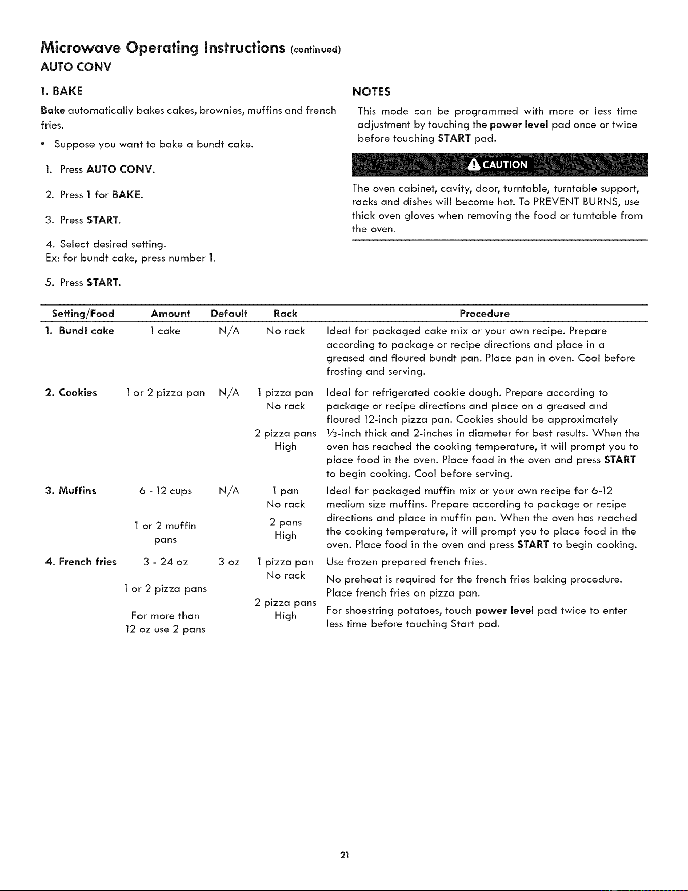
AUTO CONV
1. BAKE
Bake automatically bakes cakes, brownies, muffins and french
fries.
° Suppose you want to bake a bundt cake.
1. Press AUTO CONV.
2. Press 1 for BAKE.
3. Press START.
4. Select desired setting.
Ex: for bundt cake, press number 1.
5. Press START.
NOTES
This mode can be programmed with more or less time
adjustment by touching the power level pad once or twice
before touching START pad.
The oven cabinet, cavity, door, turntable, turntable support,
racks and dishes wiii become hot. To PREVENT BURNS, use
thick oven gloves when removing the food or turntable from
the oven.
Sefflng/Food Amount Default Rack Procedure
1. Bund| cake 1 cake N/A No rack Ideal for packaged cake mix or your own recipe. Prepare
according to package or recipe directions and place in a
greased and floured bundt pan. Place pan in oven. Cool before
frosting and serving.
2. Cookies 1 or 2 pizza pan N/A 1 pizza pan
No rack
2 pizza pans
High
3. Muffins 6 - 12 cups N/A 1 pan
No rack
1 or 2 muffin 2 pans
pans High
4. French fries 3 - 24 oz 3 oz 1 pizza pan
No rack
1 or 2 pizza pans
2 pizza pans
For more than High
12 oz use 2 pans
Ideal for refrigerated cookie dough. Prepare according to
package or recipe directions and place on a greased and
floured 12-inch pizza pan. Cooldes should be approximately
1/3-inch thick and 2-inches in diameter for best results. When the
oven has reached the cooking temperature, it will prompt you to
place food in the oven. Place food in the oven and press START
to begin cooking. Cool before serving.
Ideal for packaged muffin mix or your own recipe for 6-12
medium size muffins. Prepare according to package or recipe
directions and place in muffin pan. When the oven has reached
the cooking temperature, it will prompt you to place food in the
oven. Place food in the oven and press START to begin cooking.
Use frozen prepared french fries.
No preheat is required for the french fries baking procedure.
Place french fries on pizza pan.
For shoestring potatoes, touch power level pad twice to enter
Jess time before touching Start pad.
21
Microwave Operating Instructions (continued)
AUTO CONY
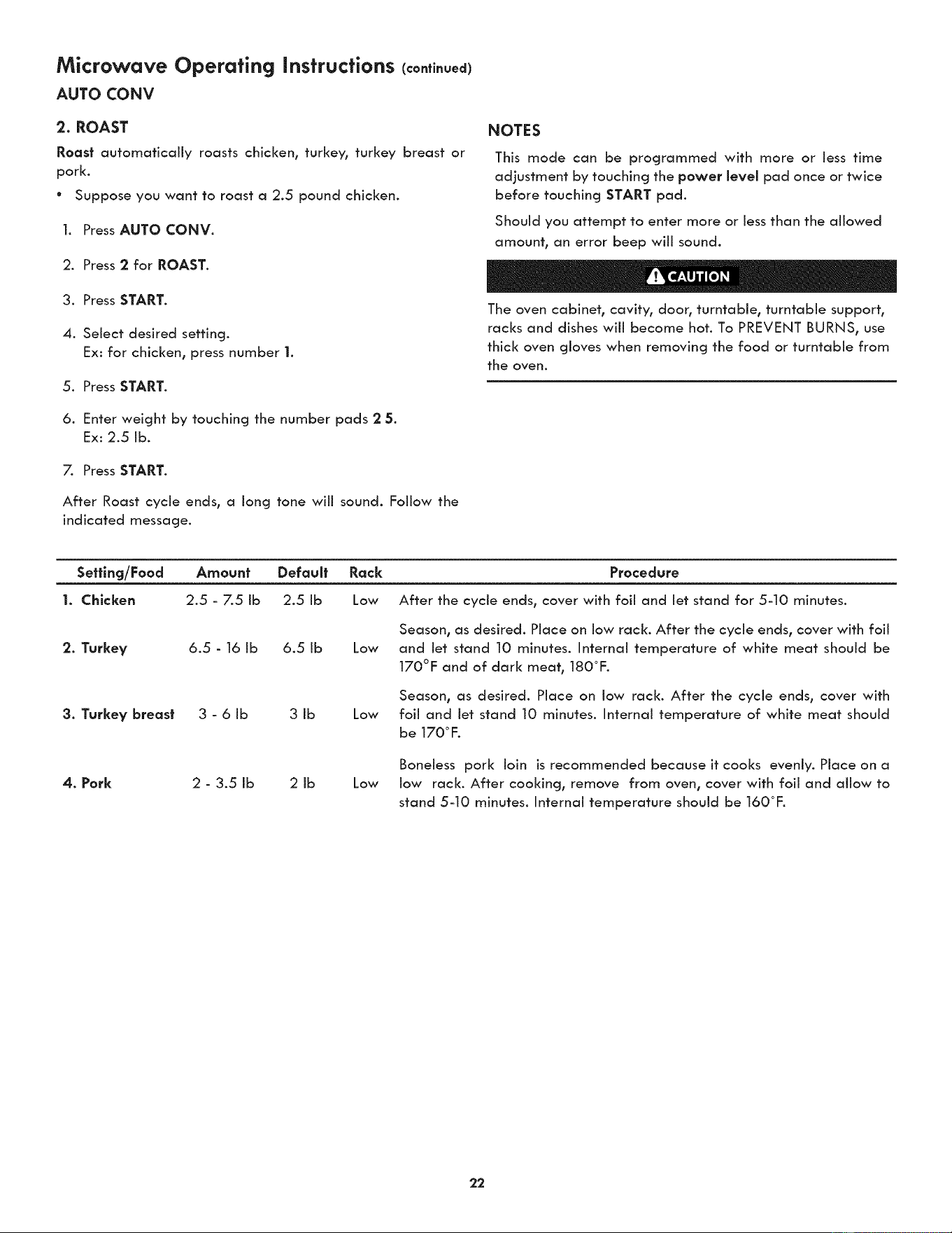
2. ROAST
Roost automatically roasts chicken, turkey, turkey breast or
pork.
° Suppose you want to roast a 2.5 pound chicken.
1. Press AUTO CONV.
2. Press 2 for ROAST.
3. Press START.
4. Select desired setting.
Ex: for chicken, press number 1.
5. Press START.
6. Enter weight by touching the number pads 2 5.
Ex: 2.5 lb.
7. Press START.
After Roast cycle ends, a long tone wiii sound. Follow the
indicated message.
NOTES
This mode can be programmed with more or less time
adjustment by touching the power level pad once or twice
before touching START pad.
Should you attempt to enter more or less than the allowed
amount, an error beep will sound.
The oven cabinet, cavity, door, turntable, turntable support,
racks and dishes will become hot. To PREVENT BURNS, use
thick oven gloves when removing the food or turntable from
the oven.
Sefflng/Food
1. Chicken
Amount Default Rock Procedure
2.5 - 7.5 ib 2.5 ib Low After the cycle ends, cover with foil and let stand for 5-10 minutes.
2. Turkey 6.5 - 16 Ib 6.5 Ib
3. Turkey breast 3 - 6 Ib 3 Ib
4. Pork 2 - 3.5 Ib 2 Ib
Season, as desired. Place on low rack. After the cycle ends, cover with foil
Low and Jet stand 10 minutes. Internal temperature of white meat should be
170°F and of dark meat, 180°F.
Season, as desired. Place on low rack. After the cycle ends, cover with
Low foil and let stand 10 minutes. Internal temperature of white meat should
be 170° F.
Boneless pork loin isrecommended because it cooks evenly. Place on a
Low low rack. After cooking, remove from oven, cover with foil and allow to
stand 5-10 minutes. Internal temperature should be 160°F.
22
Microwave Operating Instructions (continued)
AUTO CONV
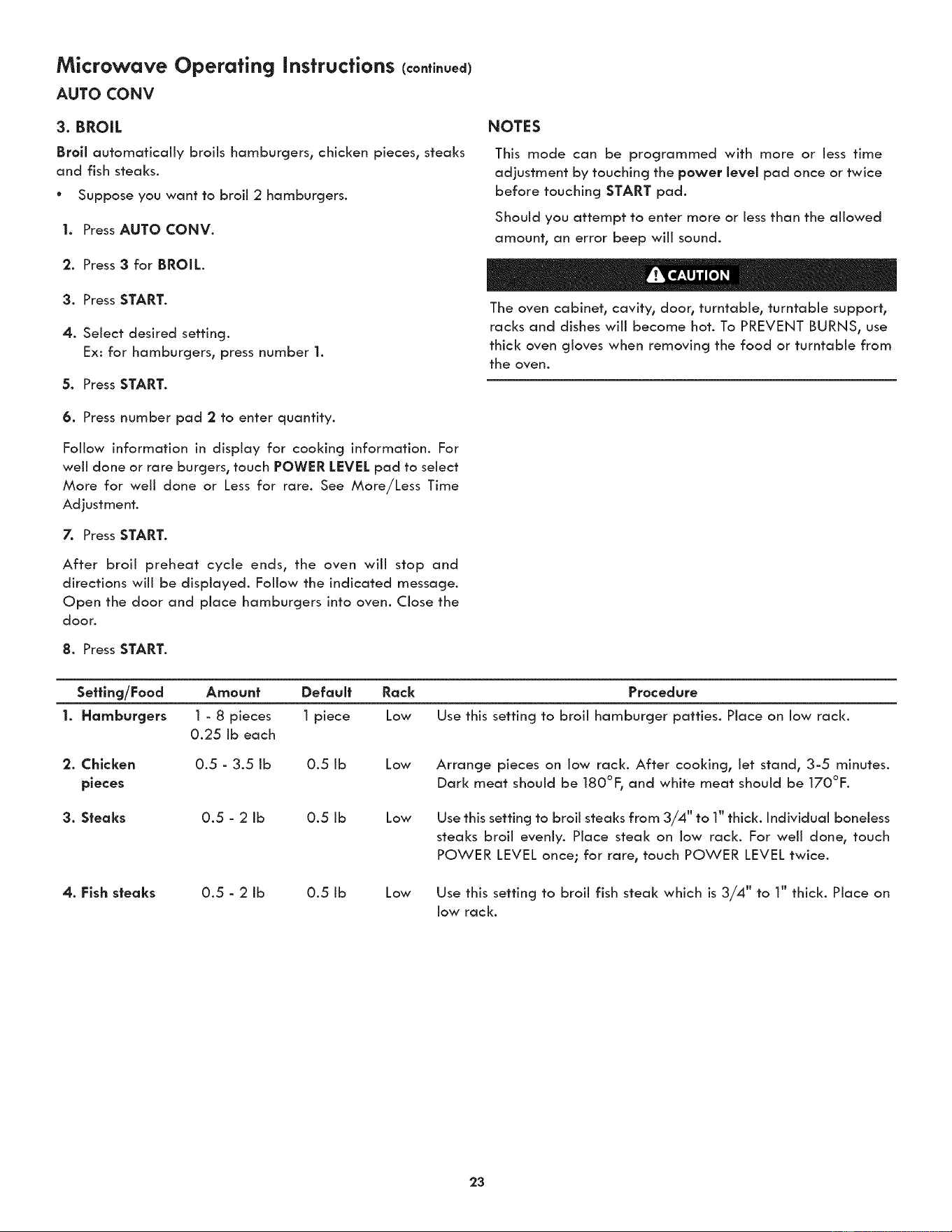
3. BROIL
Broll automatically broils hamburgers, chicken pieces, steaks
and fish steaks.
° Suppose you want to broil 2 hamburgers.
I. Press AUTO CONV.
2. Press 3 for BROIL.
3. Press START.
4. Select desired setting.
Ex: for hamburgers, press number 1.
5. Press START.
6. Press number pad 2 to enter quantity.
Follow information in display for cooking information. For
well done or rare burgers, touch POWER LEVEL pad to select
More for well done or Less for rare. See More/Less Time
Adjustment.
7. Press START.
After broil preheat cycle ends, the oven will stop and
directions will be displayed. Follow the indicated message.
Open the door and place hamburgers into oven. Close the
door.
8. Press START.
NOTES
This mode can be programmed with more or Jess time
adjustment by touching the power level pad once or twice
before touching START pad.
Should you attempt to enter more or less than the allowed
amount, an error beep will sound.
The oven cabinet, cavity, door, turntable, turntable support,
racks and dishes will become hot. To PREVENT BURNS, use
thick oven gloves when removing the food or turntable from
the oven.
Sefflng/Food Amount Default
I. Hamburgers 1 - 8 pieces 1 piece
0.25 ib each
2. Chicken
pieces
Rack Procedure
Low Use this setting to broil hamburger patties. Place on low rack.
0.5 - 3.5 ib 0.5 ib Low
3. Steaks 0.5 - 2 ib 0.5 ib
4. Fish steaks 0.5 - 2 ib 0.5 ib
Arrange pieces on low rack. After cooking, let stand, 3-5 minutes.
Dark meat should be 180°F, and white meat should be 170°F.
Low
Use this setting to broil steaks from 3/4" to 1" thick. Individual boneless
steaks broil evenly. Place steal< on low rack. For well done, touch
POWER LEVEL once; for rare, touch POWER LEVEL twice.
Low
Use this setting to broil fish steal< which is 3/4" to 1" thick. Place on
low rack.
23
Microwave Operating Instructions (continued)
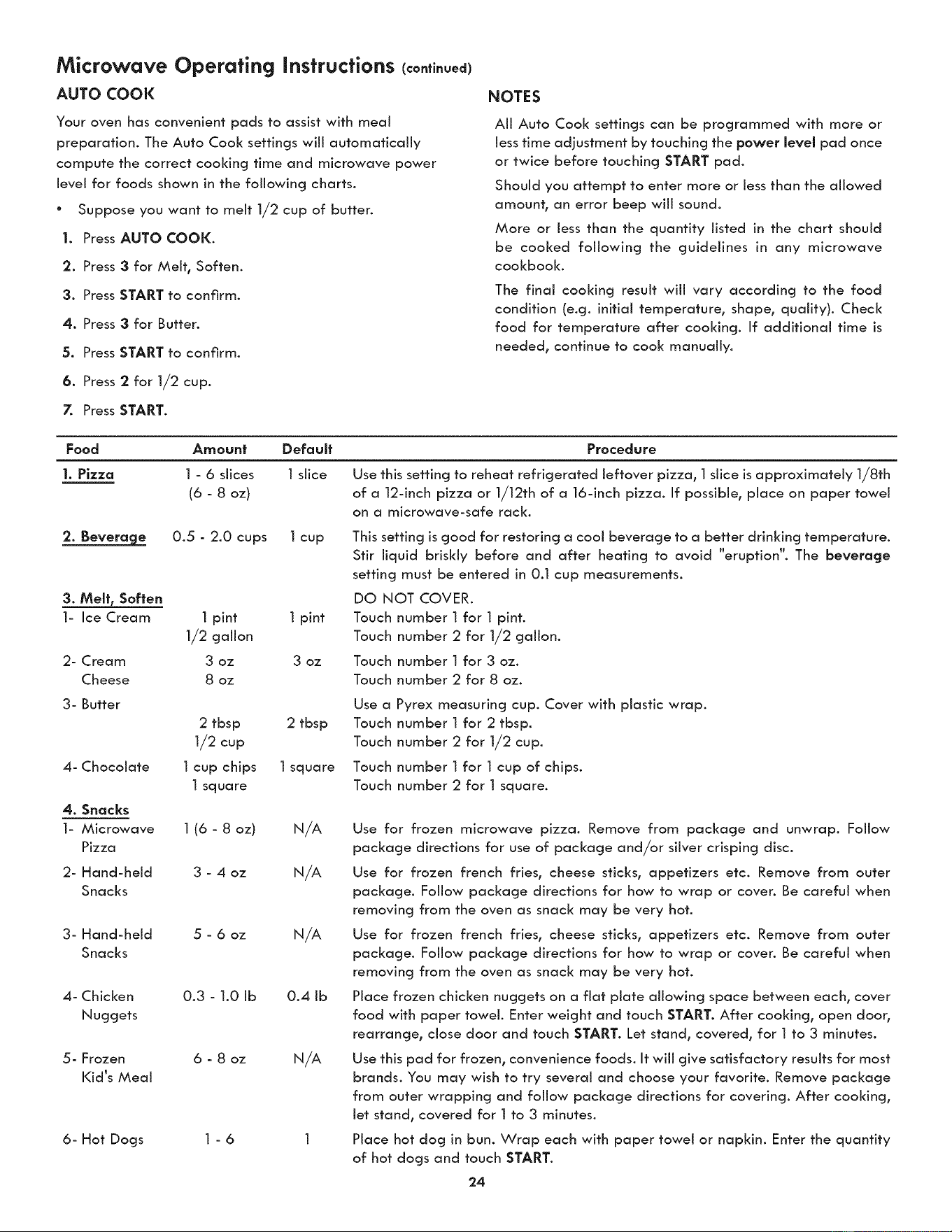
AUTO COOK
Your oven has convenient pads to assist with meal
preparation. The Auto Cool< settings will automatically
compute the correct cooking time and microwave power
level for foods shown in the following charts.
° Suppose you want to melt 1/2 cup of butter.
I. Press AUTO COOK.
2. Press 3 for Melt, Soften.
3. Press START to confirm,
4. Press 3 for Butter.
5. Press START to confirm.
6. Press 2 for 1/2 cup.
7. Press START.
NOTES
All Auto Cool< settings can be programmed with more or
less time adjustment by touching the power level pad once
or twice before touching START pad.
Should you attempt to enter more or less than the allowed
amount, an error beep will sound.
More or less than the quantity listed in the chart should
be cooked following the guidelines in any microwave
cookbook.
The final cooking result will vary according to the food
condition (e.g. initial temperature, shape, quality). Check
food for temperature after cooking. If additional time is
needed, continue to cool< manually.
Food Amount Default
I. Pizza I - 6 slices I slice
(6 - 8 oz)
2. Beverage 0.5 - 2.0 cups 1 cup
3. Melt, Soften
1- Ice Cream
2- Cream
Cheese
3- Butter
4- Chocolate
4. Snacks
1- Microwave
Pizza
2- Hand-held
Snacks
3- Hand-held
Snacks
4- Chicken
Nuggets
5- Frozen
Kid's Meal
6- Hot Dogs
1 pint 1 pint
1/2 gallon
3 oz 3 oz
8 oz
Procedure
Use this setting to reheat refrigerated leftover pizza, 1 slice is approximately 1/8th
of a 12-inch pizza or 1/12th of a 16-inch pizza. If possible, place on paper towel
on a microwave-safe rack.
This setting is good for restoring a cool beverage to a better drinking temperature.
Stir liquid briskly before and after heating to avoid "eruption". The beverage
setting must be entered in 0.1 cup measurements.
DQ NOT COVER.
Touch number 1 for 1 pint.
Touch number 2 for 1/2 gallon.
Touch number 1 for 3 oz.
Touch number 2 for 8 oz.
Use a
2 tbsp 2 tbsp Touch
1/2 cup Touch
1 cup chips 1 square Touch
1 square Touch
1 (6 - 8 oz) N/A
3 - 4 oz N/A
5 - 6 oz N/A
0.3 - 1.0 Ib 0.4 Ib
6 - 8 oz N/A
1-6
Pyrex measuring cup. Cover with plastic wrap.
number 1 for 2 tbsp.
number 2 for 1/2 cup.
number 1 for 1 cup of chips.
number 2 for 1 square.
Use for frozen microwave pizza. Remove from package and unwrap. Follow
package directions for use of package and/or silver crisping disc.
Use for frozen french fries, cheese sticks, appetizers etc. Remove from outer
package. Follow package directions for how to wrap or coven Be careful when
removing from the oven as snack may be very hot.
Use for frozen french fries, cheese sticks, appetizers etc. Remove from outer
package. Follow pad<age directions for how to wrap or coven Be careful when
removing from the oven as snack may be very hot.
Place frozen chicken nuggets on a flat plate allowing space between each, cover
food with paper towel. Enter weight and touch START. After cooking, open door,
rearrange, close door and touch START. Let stand, covered, for 1 to 3 minutes.
Use this pad for frozen, convenience foods. It will give satisfactory results for most
brands. You may wish to try several and choose your favorite. Remove package
from outer wrapping and follow package directions for covering. After cooking,
let stand, covered for 1 to 3 minutes.
Place hot dog in bun. Wrap each with paper towel or napkin. Enter the quantity
of hot dogs and touch START.
24
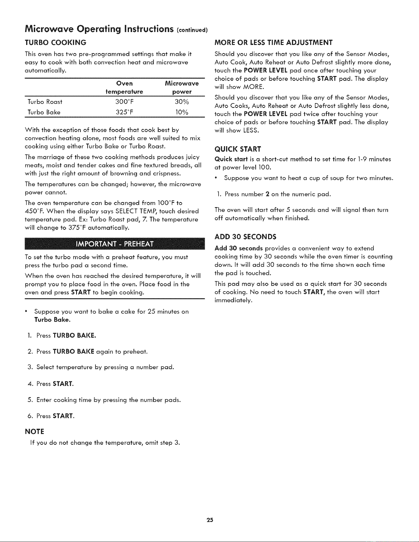
Microwave Operating Instructions (continued)
TURBO COOKING
This oven has two pre-programmed settings that make it
easy to cook with Both convection heat and microwave
automatically.
Oven Microwave
temperature power
Turbo Roast 300°F 30%
Turbo Bake 325°F 10%
With the exception of those foods that cook best by
convection heating alone, most foods are well suited to mix
cooking using either Turbo Bake or Turbo Roast.
The marriage of these two cooking methods produces juicy
meats, moist and tender cakes and fine textured breads, all
with just the right amount of browning and crispness.
The temperatures can be changed; however, the microwave
power cannot.
The oven temperature can be changed from 100°F to
450°F. When the display says SELECT TEMPI touch desired
temperature pad. Ex: Turbo Roast pad, 7. The temperature
will change to 375°F automatically.
To set the turbo mode with a preheat feature, you must
press the turbo pad a second time.
When the oven has reached the desired temperature, it will
prompt you to place food in the oven. Place food in the
oven and press START to begin cooking.
° Suppose you want to bake a cake for 25 minutes on
Turbo Bake.
1. Press TURBO BAKE.
2. Press TURBO BAKE again to preheat.
3. Select temperature by pressing a number pad.
4. Press START.
5. Enter cooking time by pressing the number pads.
6. Press START.
NOTE
If you do not change the temperature, omit step 3.
MORE OR LESSTIME ADJUSTMENT
Should you discover that you like any of the Sensor Modes,
Auto Cook, Auto Reheat or Auto Defrost slightly more done,
touch the POWER LEVEL pad once after touching your
choice of pads or before touching START pad. The display
will show MORE.
Should you discover that you like any of the Sensor Modes,
Auto Cooks, Auto Reheat or Auto Defrost slightly less done,
touch the POWER LEVEL pad twice after touching your
choice of pads or before touching START pad. The display
will show LESS.
QUICK START
Quick start is a short-cut method to set time for 1-9 minutes
at power levei 100.
* Suppose you want to heat a cup of soup for two minutes.
1. Press number 2 on the numeric pad.
The oven wiii start after 5 seconds and wiii signal then turn
off automatically when finished.
ADD 30 SECONDS
Add 30 seconds provides a convenient way to extend
cooking time by 30 seconds while the oven timer is counting
down. It will add 30 seconds to the time shown each time
the pad is touched.
This pad may also be used as a quick start for 30 seconds
of cooking. No need to touch START, the oven will start
immediately.
25
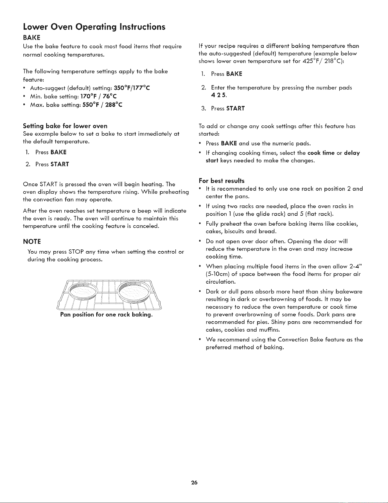
Lower Oven Operating instructions
BAKE
Use the bake feature to cool< most food items that require
normal cooking temperatures.
The following temperature settings apply to the bake
feature:
° Auto-suggest (default) setting: 350°F/177°C
° Min. bake setting: 170°F / 76°C
° Max. bake setting: 550°F / 288°C
If your recipe requires a different baking temperature than
the auto-suggested (default) temperature (example below
shows lower oven temperature set for 425°F/218°C):
1. Press BAKE
2. Enter the temperature by pressing the number pads
425.
3. Press START
Setting bake for lower oven
See example below to set a bake to start immediately at
the default temperature.
1. Press BAKE
2. Press START
Once START is pressed the oven wiii begin heating. The
oven display shows the temperature rising. While preheating
the convection fan may operate.
After the oven reaches set temperature a beep will indicate
the oven is ready. The oven will continue to maintain this
temperature until the cooking feature is canceled.
NOTE
You may press STOP any time when setting the control or
during the cooking process.
Pan position for one rack baking.
To add or change any cook settings after this feature has
started:
* Press BAKE and use the numeric pads.
* If changing cooking times, select the cook time or delay
start keys needed to make the changes.
For best results
* It is recommended to only use one rack on position 2 and
center the pans.
° If using two racks are needed, place the oven racks in
position 1 (use the glide rack) and 5 (fiat rack).
° Fully preheat the oven before baking items like cookies,
cakes, biscuits and bread.
° Do not open over door often. Opening the door will
reduce the temperature in the oven and may increase
cooking time.
° When placing multiple food items in the oven allow 2-4"
(5-10cm) of space between the food items for proper air
circulation.
* Dark or duli pans absorb more heat than shiny bakeware
resulting in dark or overbrowning of foods. It may be
necessary to reduce the oven temperature or cook time
to prevent overbrowning of some foods. Dark pans are
recommended for pies. Shiny pans are recommended for
cakes, cookies and mumns.
* We recommend using the Convection Bake feature as the
preferred method of baking.
26
Lower Oven Operating instructions (continued)
COOK TiME
Adding a cook duration when baking is beneficial when a
recipe requires a specific temperature and period of time to
cook. Following the recipe cook time helps ensure the best
possible results.
Cool< time may be set with the following features:
° Bake
• Conv Bake
° Conv Roast
• Slow Cook
See example below to set the lower oven for bak% starting
immediately with preheating to the auto-suggest (default)
setting of 350°F (176°C) and then to automatically turn off:
after 30 minutes:
l. Press BAKE
2. Press START
3. Press COOl( TIME
4. Enter 30 minutes
5. Press START
Once START is pressed the oven wiii cook and after 30
minutes automatically shut-off.
NOTE
You may press STOP any time when setting the control or
during the cooking process.
When the Cook Time finishes:
l. "End" and the time of day will show in display. The oven
will shut off automatically.
2. The control will beep 3 times. The control will continue
to beep 3 times every 30 seconds until STOP is pressed.
DELAY START (with cook time)
Adding a cook duration along with a specific start time
gives the same benefits as the cook time option in addition
to controlling exactly when the cooking process will begin
and end.
Cool< time and delay start may be set with the following
features:
° Bake
" Conv Bake
• Conv Roast
• Slow Cool<
" Self Clean
See example below to set the lower oven with preheating for
bake at 375°F (177°C) for 50 minutes and to automatically
start at 5:30:
Preheat the oven if necessary
1. Press BAKE
2. Enter 375°F
3. Press START
4. Press COOK TIME
5. Enter 50 minutes
6. Press START
7. Press DELAY START
8. Enter 5:30
9. Press START
Once START is pressed_ the oven will calculate the start time
at which the oven will begin heating.
The oven will continue to maintain this temperature for the
selected time or until the cooking feature is canceled.
NOTE
When setting the DELAY START option be sure the correct
time of day is set.
You may press STOP any time when setting the control or
during the cooking process.
You may also choose to use DELAY START with no COOK
TIME.
27
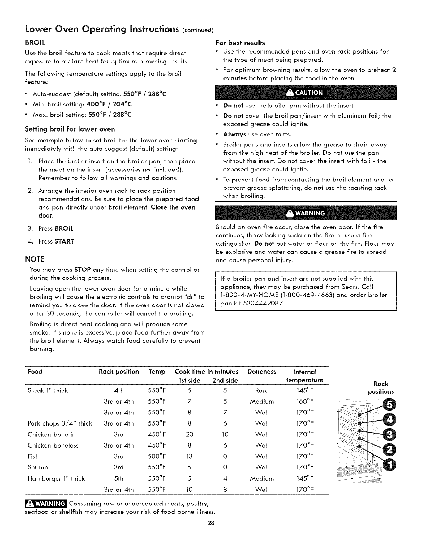
Lower Oven Operating instructions (continued)
BROIL
Use the broil feature to cook meats that require direct
exposure to radiant heat for optimum browning results.
The following temperature settings apply to the broil
feature:
* Auto-suggest (default) setting: 550°F / 288°C
° Min. broil setting: 400°F / 204°C
° Max. broil setting: 550°F / 288°C
Setting broll for lower oven
See example below to set broil for the lower oven starting
immediately with the auto-suggest (default) setting:
.
Place the broiler insert on the broiler pan, then place
the meat on the insert (accessories not included).
Remember to follow all warnings and cautions.
Arrange the interior oven rack to rack position
recommendations. Be sure to place the prepared food
and pan directly under broil element. Close the oven
door.
3. Press BROIL
4. Press START
NOTE
You may press STOP any time when setting the control or
during the cooking process.
Leaving open the lower oven door for a minute while
broiling will cause the electronic controls to prompt "dr" to
remind you to close the door. If the oven door is not closed
after 30 seconds° the controller wiii cancel the broiling.
Broiling is direct heat cooking and wiii produce some
smoke. If smoke is excessive, place food further away from
the broil element. Always watch food carefully to prevent
burning.
For best results
* Use the recommended pans and oven rack positions for
the type of meat being prepared.
° For optimum browning results, allow the oven to preheat 2
minutes before placing the food in the oven.
° Do not use the broiler pan without the insert.
° Do not cover the broil pan/insert with aluminum foil; the
exposed grease could ignite.
° Always use oven mitts.
° Broiler pans and inserts allow the grease to drain away
from the high heat of the broiler. Do not use the pan
without the insert. Do not cover the insert with foil - the
exposed grease could ignite.
° To prevent food from contacting the broil element and to
prevent grease splattering, do not use the roasting rack
when broiling.
Should an oven fire occur, close the oven door. If the fire
continues, throw baking soda on the fire or use a fire
extinguisher. Do not put water or flour on the fire. Flour may
be explosive and water can cause a grease fire to spread
and cause personal injury.
If a broiler pan and insert are not supplied with this
appliance, they may be purchased from Sears. Call
1-800-4-MY-HOME (1-800-469-4663) and order broiler
pan kit 5304442087.
Food Rack position Temp Cook flme in minutes Doneness Infernal
1st side 2rid side temperature
Steak 1" thick 4th 550 ° F 5 5 Rare 145 ° F
3rd or 4th 550°F 7 5 Medium 160°F
3rd or 4th 550°F 8 7 Well 170°F
3rd or 4th 550°F 8 6 Well 170°F
3rd 450°F 20 10 Weii 170°F
3rd or 4th 450°F 8 6 Well 170°F
3rd 500°F 13 0 Well 170°F
3rd 550°F 5 0 Well 170°F
5th 550 °F 5 4 Medium 145 ° F
3rd or 4th 550°F 10 8 Weii 170°F
Pork chops 3/4" thick
Chicken-bone in
Chicken-boneless
Fish
Shrimp
Hamburger 1" thick
Consuming raw or undercooked meats, poultry,
seafood or shellfish may increase your risk of food borne illness.
28
Rack
positions
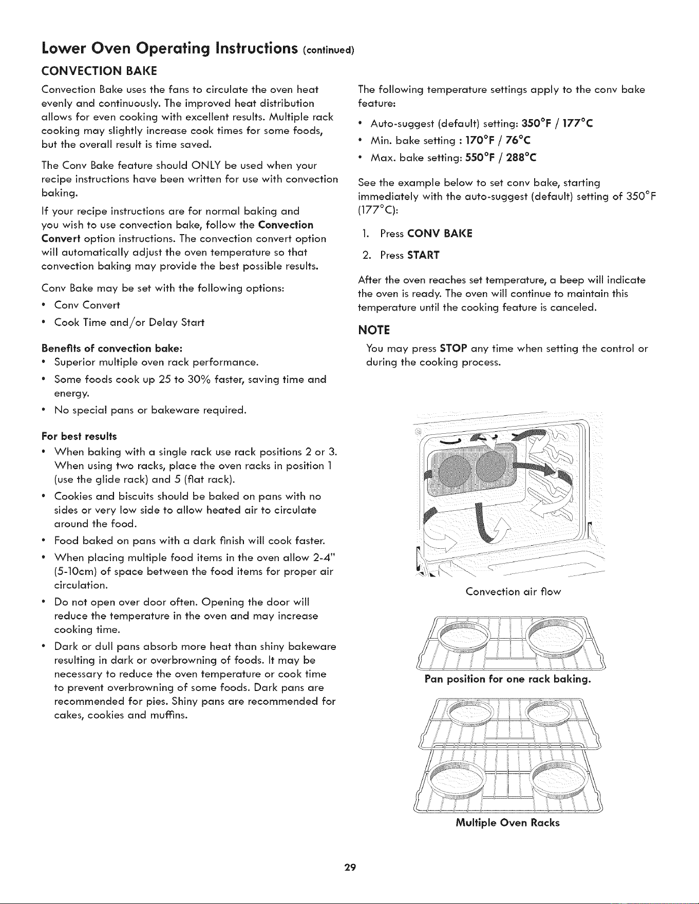
Lower Oven Operating Instructions (co.ti.ued)
CONVECTION BAKE
Convection Bake uses the fans to circulate the oven heat
evenly and continuously. The improved heat distribution
allows for even cooking with excellent results. Multiple rack
cooking may slightly increase cook times for some foods_
but the overall result is time saved.
The Conv Baize feature should ONLY be used when your
recipe instructions have been written for use with convection
baking.
If your recipe instructions are for normal baking and
you wish to use convection baize, follow the Convection
Convert option instructions. The convection convert option
will automatically adjust the oven temperature so that
convection baking may provide the best possible results.
Conv Baize may be set with the following options:
" Conv Convert
° Cook Time and/or Delay Start
Benefits of convection bake:
° Superior multiple oven rack performance.
° Some foods cook up 25 to 30% faster° saving time and
energy.
° No special pans or bakeware required.
For best results
* When baking with a single rack use rack positions 2 or 3.
When using two racks_ place the oven racks in position 1
(use the glide rack) and 5 (fiat rack).
° Cookies and biscuits should be baked on pans with no
sides or very low side to allow heated air to circulate
around the food.
e
e
Food baked on pans with a dark finish will cook faster.
When placing multiple food items in the oven allow 2-4"
(5-10cm) of space between the food items for proper air
circulation.
Do not open over door often. Opening the door will
reduce the temperature in the oven and may increase
cooking time.
Dark or dull pans absorb more heat than shiny bakeware
resulting in dark or overbrowning of foods. It may be
necessary to reduce the oven temperature or cook time
to prevent overbrowning of some foods. Dark pans are
recommended for pies. Shiny pans are recommended for
cakes, cookies and mumns.
The following temperature settings apply to the conv baize
feature:
° Auto-suggest (default) setting: 350°F / 177°C
" Min. baize setting : 170°F / 76°C
* Max. baize setting: 550°F / 288°C
See the example below to set conv bake_ starting
immediately with the auto-suggest (default) setting of 350°F
(177°C):
1. Press CONV BAI(I_
2. Press START
After the oven reaches set temperature_ a beep will indicate
the oven is ready. The oven will continue to maintain this
temperature until the cooking feature is canceled.
NOTE
You may press STOP any time when setting the control or
during the cooking process.
Convection air flow
29
Pan position for one rack baking.
Multlple Oven Racks
Lower Oven Operating Instructions (continued)
CONVECTION CONVERT
The conv convert option allows you to convert any normal
baking recipe using the convection bake feature. The control
uses the normal recipe settings and adjusts to a lower
temperature for convection baking. Conv convert must be
used with Conv Baize feature.
Benefits of cony bake using cony convert option:
° Superior multiple oven rack performance.
° Some foods cool< up 25 to 30% faster, saving time and
energy.
• No special pans or bakeware required.
For best results
° Place food items using the recommended rack positions.
° When baking with a single rack use rack positions 2 or 3.
When using two racks, place the oven racks in position 2
(1 for glide rack) and 5 (4 for glide rack).
° Cookies and biscuits should be baked on pans with no
sides or very low side to allow heated air to circulate
around the food.
e
e
Food baked on pans with a dark finish will cook faster.
When placing multiple food items in the oven allow 2-4"
(5-10cm) of space between the food items for proper air
circulation.
Do not open over door often. Opening the door will
reduce the temperature in the oven and may increase
cooking time.
Dark or dull pans absorb more heat than shiny bakeware
resulting in dark or overbrowning of foods. It may be
necessary to reduce the oven temperature or cook time
to prevent overbrowning of some foods. Dark pans are
recommended for pies. Shiny pans are recommended for
cakes, cookies and muffins.
See the example below to set cony baize, starting
immediately with the auto-suggest (default) setting of 350°F
(177°C) and adding the cony convert option.
1. Press CONV BAKE
2. Press CONV CONVERT
3. Press START
After the oven reaches the converted set temperature, a
beep will indicate the oven is ready.
The added conv convert option will automatically lower the
set temperature you set from the baize recipe to an adjusted
cony baize temperature.
When conv convert is used with cool< time "CF" (Check
Food) will be displayed when the cook time is 75°/0
complete. The control will also beep at regular intervals until
baking has finished. For the Check Food function to operate,
the cook time must be entered before the Cony Convert pad
is pressed.
NOTE
You may press STOP any time when setting the control or
during the cooking process.
3O
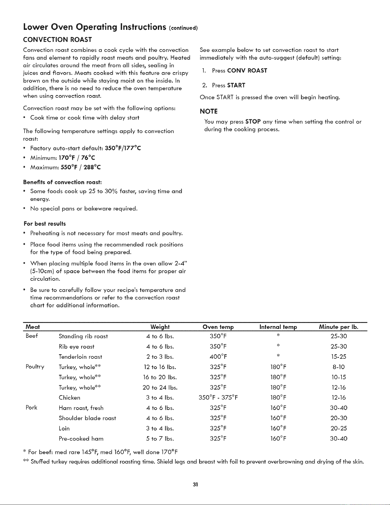
Lower Oven Operating Instructions (co.ti.uea)
CONVECTION ROAST
Convection roast combines a cool< cycle with the convection
fans and element to rapidly roast meats and poultry. Heated
air circulates around the meat from all sides, sealing in
juices and flavors. Meats cooked with this feature are crispy
brown on the outside while staying moist on the inside. In
addition, there is no need to reduce the oven temperature
when using convection roast.
Convection roast may be set with the following options:
° Cool< time or cook time with delay start
The following temperature settings apply to convection
roast:
* Factory auto-start default: 350°F/177°C
* Minimum: 170°F / 76°C
° Maximum: 550°F / 288°C
Benefits of convection roast:
° Some foods cool< up 25 to 30% faster, saving time and
energy.
° No special pans or bakeware required.
For best results
° Preheating is not necessary for most meats and poultry.
° Place food items using the recommended rack positions
for the type of food being prepared.
• When placing multiple food items in the oven allow 2-4"
(5-10cm) of space between the food items for proper air
circulation.
° Be sure to carefully follow your recipe's temperature and
time recommendations or refer to the convection roast
chart for additional information.
See example below to set convection roast to start
immediately with the auto-suggest (default) setting:
1. Press CONV ROAST
2. Press START
Once START is pressed the oven will begin heating.
NOTE
You may press STOP any time when setting the control or
during the cooking process.
Poultry
Pork
Weight
Standing rib roast 4 to 6 Ibs.
Rib eye roast 4 to 6 Ibs.
Tenderloin roast 2 to 3 Ibs.
Turkey, whole _ 12 to 16 Ibs.
Turkey, whole _ 16 to 20 Ibs.
Turkey, whole _ 20 to 24 Ibs.
Chicken 3 to 4 Ibs.
Oven letup Internal letup Minute per lb.
350°F _ 25-30
350°F :_ 25-30
400°F _ 15-25
325°F 180°F 8-10
325°F 180°F 10-15
325°F 180°F 12-16
350°F - 375°F 180°F 12-16
325 ° F 160 °F 30-40
325 ° F 160 °F 20-30
325 ° F 160 °F 20-25
325 ° F 160 °F 30-40
Ham roast, fresh 4 to 6 Ibs.
Shoulder blade roast 4 to 6 Ibs.
Loin 3 to 4 Ibs.
Pre-cooked ham 5 to 7 Ibs.
For beef: reed rare 145°F, reed 160°F, well done 170°F
_ Stuffed turkey requires additional roasting time. Shield legs and breast with foil to prevent overbrowning and drying of the skin.
31
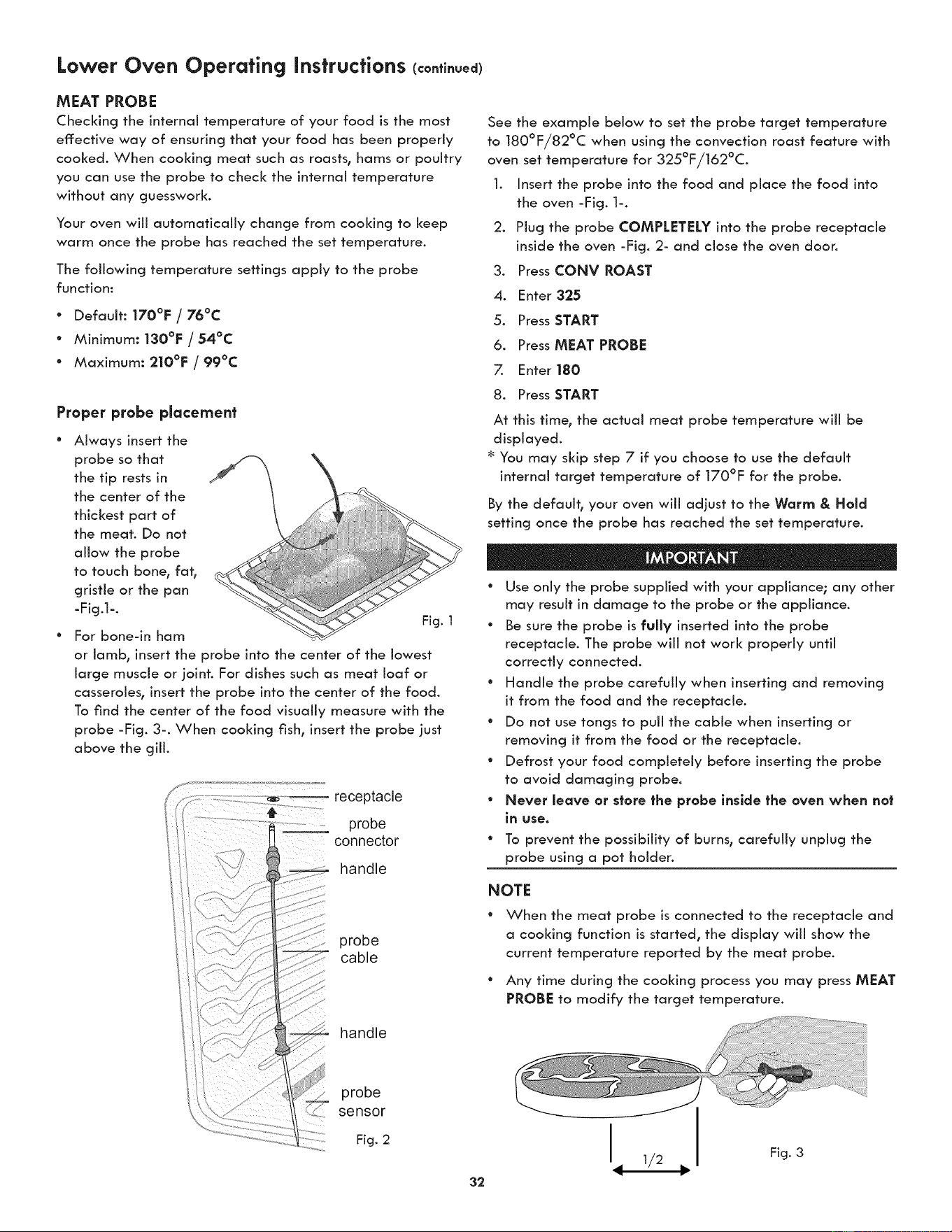
Lower Oven Operating instructions (continued)
MEAT PROBE
Checking the internal temperature of your food is the most
effective way of ensuring that your food has been properly
cooked. When cooking meat such as roasts, hams or poultry
you can use the probe to check the internal temperature
without any guesswork.
Your oven will automatically change from cooking to keep
warm once the probe has reached the set temperature.
The following temperature settings apply to the probe
function:
° Default: 170°F / 76°C
° Minimum: 130°F / 54°C
° Maximum: 210°F / 99°C
Proper probe placement
Always insert the
probe so that
the tip rests in
the center of the
thickest part of
the meat. Do not
allow the probe
to touch bone, fat,
gristle or the pan
-Fig.l-.
Fig. 1
For bone-in ham
or lamb, insert the probe into the center of the lowest
large muscle or joint. For dishes such as meat loaf or
casseroles, insert the probe into the center of the food.
To find the center of the food visually measure with the
probe -Fig. 3-. When cooking fish, insert the probe just
above the gill.
receptacle
probe
connector
handle
probe
cable
handle
See the example below to set the probe target temperature
to 180°F/82°C when using the convection roast feature with
oven set temperature for 325°F/162°C.
1. Insert the probe into the food and place the food into
the oven -Fig. 1-.
2. Plug the probe COMPLETELY into the probe receptacle
inside the oven -Fig. 2- and close the oven door.
Press CONY ROAST.
4. Enter 325
5. Press START
6. Press MEAT PROBE
7. Enter 180
8. Press START
At this time, the actual meat probe temperature wiJJ be
displayed.
* You may skip step 7 if you choose to use the default
internal target temperature of 170°F for the probe.
By the default, your oven wiii adjust to the Worm & Hold
setting once the probe has reached the set temperature.
° Use only the probe supplied with your appliance; any other
may result in damage to the probe or the appliance.
° Be sure the probe is fully inserted into the probe
receptacle. The probe will not work properly until
correctly connected.
° Handle the probe carefully when inserting and removing
it from the food and the receptacle.
° Do not use tongs to pull the cable when inserting or
removing it from the food or the receptacle.
° Defrost your food completely before inserting the probe
to avoid damaging probe.
° Never leave or store the probe inside the oven when not
in use.
* To prevent the possibility of burns, carefully unplug the
probe using a pot holder.
NOTE
° When the meat probe is connected to the receptacle and
a cooking function is started, the display will show the
current temperature reported by the meat probe.
° Any time during the cooking process you may press MEAT
PROBE to modify the target temperature.
probe
sensor
Fig. 2
32
h 1/2
Fig. 3
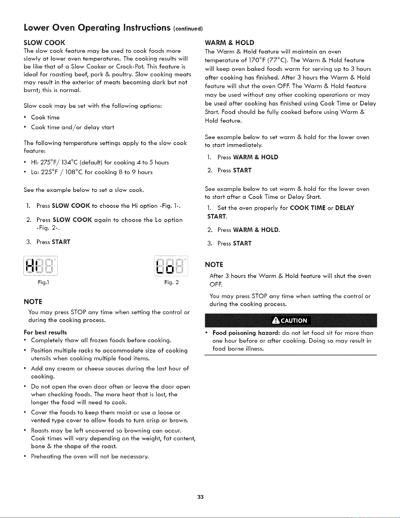
Lower Oven Operating instructions (continued)
SLOW COOl(
The slow cool< feature may be used to cool< foods more
slowly at lower oven temperatures. The cooking results will
be like that of a Slow Cooker or Crock-Pot. This feature is
ideal for roasting beef, pork & poultry. Slow cooking meats
may result in the exterior of meats becoming dark but not
burnt; this is normal.
Slow cool< may be set with the following options:
* Cool< time
* Cool( time and/or delay start
The following temperature settings apply to the slow cool<
feature:
* HI: 275°F/134°C (default) for cooking 4 to 5 hours
* Lo: 225°F / 108°C for cooldng 8 to 9 hours
See the example below to set a slow cool<.
1. Press SLOW COOK to choose the Hi option -Fig. 1-.
2. Press SLOW COOK again to choose the Lo option
-Fig. 2-.
3. Press START
Fig.1 Fig. 2
NOTE
You may press STOP any time when setting the control or
during the cooking process.
For best results
* Completely thaw all frozen foods before cooking.
° Position multiple racks to accommodate size of cooking
utensils when cooking multiple food items.
° Add any cream or cheese sauces during the last hour of
cooking.
° Do not open the oven door often or leave the door open
when checking foods. The more heat that is lost, the
longer the food will need to cool<.
° Cover the foods to keep them moist or use a loose or
vented type cover to allow foods to turn crisp or brown.
° Roasts may be left uncovered so browning can occur.
Cool< times will vary depending on the weight, fat content,
bone & the shape of the roast.
" Preheating the oven will not be necessary.
WARM & HOLD
The Warm & Hold feature will maintain an oven
temperature of 170°F (77°C). The Warm & Hold feature
will keep oven baked foods warm for serving up to 3 hours
after cooking has finished. After 3 hours the Warm & Hold
feature will shut the oven OFF. The Warm & Hold feature
may be used without any other cooking operations or may
be used after cooking has finished using Cool< Time or Delay
Start. Food should be fully cooked before using Warm &
Hold feature.
See example below to set warm & hold for the lower oven
to start immediately.
1. Press WARM & HOLD
2. Press START
See example below to set warm & hold for the lower oven
to start after a Cool< Time or Delay Start.
1. Set the oven properly for COOK TIME or DELAY
START.
2. PressWARM & HOLD.
3. Press START
NOTE
After 3 hours the Warm & Hold feature will shut the oven
OFF.
You may press STOP any time when setting the control or
during the cooking process.
° Food poisoning hazard: do not let food sit for more than
one hour before or after cooking. Doing so may result in
food borne illness.
33
Lower Oven Operating instructions (continued)
SABBATH MODE
This appliance provides special settings for use when
observing the Jewish Sabbath/Holidays. This mode will turn
off: aH audible tones or visual display changes normally
provided by the oven control. BAKE is the only cooking
features available while in the Sabbath mode.
You must first set the BAKE feature and temperature(s)
needed for the lower oven, the COOl( TIME option if
needed before setting the Sabbath mode. Any settings
made prior to setting the Sabbath mode wiii be visible in
the displays.
The Sabbath mode wiii override the factory preset 12 Hour
Energy Saving mode and the appliance will stay on until
the cooking features are cancelled. If any of the cooking
features are cancelled when the appliance is in the Sabbath
mode, no audible or visual indicators will be available to
verify the cancellation.
If the oven interior lights are needed, be sure to activate
them prior to setting the Sabbath mode. Once the oven light
is turned ON and the Sabbath mode is active, the oven light
will remain on until the Sabbath mode is turned off: and the
oven lights are turned off:. The oven door wiii not activate
the oven interior lights when the oven door is opened or
closed.
It is recommended that any oven temperature modification
made within an active Sabbath mode be followed with 2
presses of the START key. This will ensure the oven remains
ON even if an attempt is made to set the oven temperature
outside of its temperature range. If the oven temperature is
set outside of the temperature range, the oven will default
to the nearest available temperature. Try to set the desired
oven temperature again.
Should a power failure or interruption occur during the
Sabbath/Holidays, the appliance wiii shut OFF. When
power is restored the appliance wiii not turn back on
automatically to the original BAKE feature settings. SF
will appear in all the control display panels indicating a
Sabbath mode failure. After a power failure, the food may
be safely removed from the oven while still in the Sabbath
mode.
For further assistance, guidelines for proper usage
and a complete list of models with the Sabbath
feature, please visit the web at http:\\www.
star-k.org.
SETTING SABBATH MODE
The example below shows setting the oven to observe the
Sabbath (and Jewish holidays).
1. Press BAKE.
2 Press START
Be sure to make any additional oven setting changes
before going to step 3.
3. To enter Sabbath mode, press and hold simultaneously
both the COOK TIME and DELAY START keys together
for 3 seconds (a beep will sound) and release.
Once properly set in Sabbath mode, SAb will show in the
oven display until the Sabbath mode is cancelled.
NOTE
The oven may be turned off: at any time by first pressing
STOP (this will only turn the oven off:).
CANCELING SABBATH MODE
The example below shows how to cancel the Sabbath mode.
1. Press and hold both the COOK TiME and DELAY
START keys together for 3 seconds (a beep wiii
sound) and release.
2. Aii cooking features previously set wiii automatically
cancel once Sabbath mode has ended.
NOTE
The only keys available once the appliance is set for the
Sabbath mode are BAKE, START, STOP and the numeric
pads.
You may change the oven temperature once baking has
started (Jewish holidays only). Press BAKE, enter the oven
temperature using the numeric keys and press START
twice. Remember that the oven control wi[[ no longer
beep or dlsplay any further changes once the oven is set
in the Sabbath mode.
* Food polsonlng hazard: do not let food sit for more than
one hour before or after cooking. Doing so may result in
food borne illness.
NOTE
No Sabbath mode is available for microwave oven. Do not use
the microwave oven when the Sabbath mode is enabled.
34
Lower Oven Operating instructions (continued)
RECIPE RECALL
The Recipe Recall feature may be used to record and recall
your favorite recipe settings. This feature may store 1 setting
for each of the 3 basic cooking pads. The key pad that a
recipe may be stored with are Bake, Cony Bake and Cony
Roast. This feature will also store and recall Cook Time or
Warm & Hold added setting. Note: Pressing the Start pad
after entering cooking temperatures and times wiii start the
oven. If you wish to store the recipes but not start the oven
press STOP after pressing the STARTpad. Once a recipe
has been stored the recipe information will appear in the
display when pressing the pad in future.
See example below to store a typical cookie recipe
(example for baking at 375°F for 9 minutes and to shut-off
automatically).
Preheat _ the oven to the desired temperature.
1. Press BAKE.
2. Press 3 75.
3. Press START.
4. Press COOK TIME.
5. Enter the desired baking time. Press 9.
6 Press and hold START for 3 seconds.
This recipe is now stored with the Bake key pad.
The oven will begin to count down the cooking time
as soon as the feature is activated. If cooking requires
a preheated oven, set Cool< Time after the oven is fully
preheated.
See example below to recall a previously stored recipe
under BAKE pad.
1. Press BAKE. The stored recipe is recalled.
2. Press START.
See example below to quickly erase aii stored recipes.
1. Press and hold CONV CONVERT until the first single
beep sounds (6 seconds).
2. After the first beep press the START pad once. Any
stored recipes will be erased.
NOTE
Clearing the recipes will also reset ail other adjustments
back to the factory settings. These include 12 or 24 Hour
Time of Day display, Continuous Bake or 12 Hour Energy
Savings mode, Silent Control Operation, Fahrenheit or
Celsius Temperature Display and any Oven Temperature
adjustments that are set.
35
User Preferences
SETTING CLOCK
See the example below to set the clock to 1:30.
1. Press Q.
2. Enter 1:30 to advance to 1:30.
3. Press START to accept or press STOP to reject.
SETTING 12 OR 24 HOUR MODE
The clock display mode allows you to choose between 12
and 24 hour mode. The factory preset clock display mode is
12 hour.
See the example below to change the default mode to 24
hour.
1. Press and hold L _) for 7 seconds until CLOCK 12Hr or
24Hr appear in the display.
2. Press SELF CLEAN to switch between the 12 and 24 hour
mode.
3. Press START to accept or press STOP to reject.
ADJUSTING OVEN TEMPERATURE
User preference offset
Your appliance has been factory calibrated and tested to
ensure an accurate baking temperature. For the first few uses_
follow your recipe times and temperature recommendations
carefully.
If you feel your oven is too hot or too cool from your baking
experience_ the oven temperature may be adjusted to your
liking. The temperature may be increased up to +35°F (+19°C)
or decreased down to -35°F (-19°C) from normal.
See the example below to increase the temperature in the lower
oven.
1. Press and hold BAKE for 7 seconds until USER appear
in the display.
2. Enter the desired temperature change using the
number pads. SELF CLEAN can be pressed to lower the
temperature.
3. Press START to accept or press STOP to reject.
Do not use oven thermometers such as those found in grocery
stores to check the temperature settings inside the oven. These
thermometers may display temperatures that vary greatly from
the actual temperature.
CHANGING BETWEEN F° OR C°
Your control has the ability to display and set Fahrenheit or
Celsius temperatures. The factory preset temperature display
is Fahrenheit.
See the example below to change the default temperature
display to Celsius.
1. Press and hold BROIL for 7 seconds until F or C appear
in the display.
2. Press SELF CLEAN to switch between the F and C mode.
3. Press START to accept or press STOP to reject.
SETTING AUDIO MODE
The audio mode allows you to control the audio for the
oven control. You may turn the audio off and later return to
operating with all the normal audible sounds and alerts.
See the example below when changing the audible settings.
1. Press and hold DELAY START for 7 seconds until AUDIO
appears in the display.
2. Press SELF CLEAN to switch between the On and Off
mode.
3. Press START to accept or press STOP to reject.
SETTING 12HR ENERGY SAVING MODE
The oven control has a factory preset built-in 12 hour energy
saving feature that wiii shut off the appliance if the oven
has been heating for more than 11hours and 59 minutes.
The oven can be programmed to override this feature for
continuous baking.
See the example below to turn off 12 hour energy saving
mode.
1. Press and hold TIMER for 7 seconds until En-SAVER
appears in the display.
2. Press SELF CLEAN to switch between the On and Off
mode.
3. Press START to accept or press STOP to reject.
36
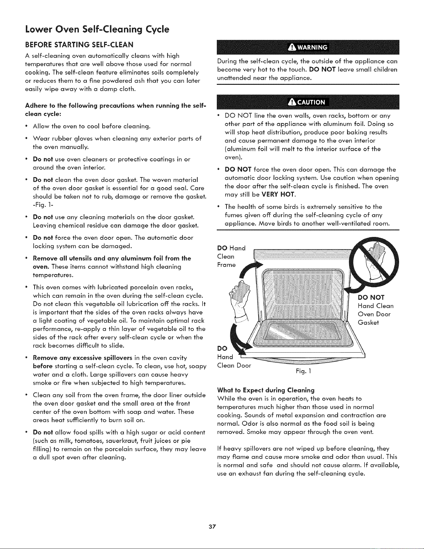
Lower Oven Self-Cleaning Cycle
BEFORE STARTING SELF=CLEAN
A self-cleaning oven automatically cleans with high
temperatures that are well above those used for normal
cooking. The self-clean feature eliminates soils completely
or reduces them to a fine powdered ash that you can later
easily wipe away with a damp cloth.
Adhere to the following precautions when running the self=
cleon cycle:
° Allow the oven to cool before cleaning.
* Wear rubber gloves when cleaning any exterior parts of
the oven manually.
* Do no| use oven cleaners or protective coatings in or
around the oven interion
DO no| dean the oven door gasket. The woven material
of the oven door gasket is essential for a good seal. Care
should be taken not to rub, damage or remove the gasket.
-Fig. 1-
Do no| use any cleaning materials on the door gasket.
Leaving chemical residue can damage the door gasket.
Do not force the oven door open. The automatic door
locking system can be damaged.
Remove all utensils and any olumlnum fall from the
oven. These items cannot withstand high cleaning
temperatures.
This oven comes with lubricated porcelain oven racks,
which can remain in the oven during the self-clean cycle.
Do not clean this vegetable oil lubrication off the racks. It
is important that the sides of the oven racks always have
a light coating of vegetable oil. To maintain optimal rack
performance, re-apply a thin layer of vegetable oil to the
sides of the rack after every self-clean cycle or when the
rack becomes difficult to slide.
Remove any excessive spliJovers in the oven cavity
before starting a self-clean cycle. To dean, use hot, soapy
water and a cloth. Large spillovers can cause heavy
smoke or fire when subjected to high temperatures.
Clean any soil from the oven frame, the door liner outside
the oven door gasket and the small area at the front
center of the oven bottom with soap and water. These
areas heat sufficiently to burn soil on.
Do not allow food spills with a high sugar or acid content
(such as mill<, tomatoes, sauerkraut, fruit juices or pie
filling) to remain on the porcelain surface, they may leave
a dull spot even after cleaning.
During the self-dean cycle, the outside of the appliance can
become very hot to the touch. DO NOT leave small children
unattended near the appliance.
° DO NOT line the oven wafts, oven racks, bottom or any
other part of the appliance with aluminum foil. Doing so
will stop heat distribution, produce poor baking results
and cause permanent damage to the oven interior
(aluminum foil will melt to the interior surface of the
oven).
DO NOT force the oven door open. This can damage the
automatic door locking system. Use caution when opening
the door after the self-dean cycle is finished. The oven
may still be VERY HOT.
° The health of some birds is extremely sensitive to the
fumes given off during the self-cleaning cycle of any
appliance. Move birds to another well-ventilated room.
DO Hand
Clean
Frame
DO NOT
Hand Clean
Oven Door
Gasket
DO
Hand
Clean Door
Fig. 1
What to Expect during CJeonlng
While the oven is in operation, the oven heats to
temperatures much higher than those used in normal
cooking. Sounds of metal expansion and contraction are
normal. Odor is also normal as the food soil is being
removed. Smoke may appear through the oven vent.
If heavy spillovers are not wiped up before cleaning, they
may flame and cause more smoke and odor than usual. This
is normal and safe and should not cause alarm. If available,
use an exhaust fan during the self-cleaning cycle.
37
Lower Oven Self-Cleanincj Cycle
SELF=CLEAN CYCLE
The SELF CLEAN pad controls the Self-Cleaning feature.
When used with a Delay Start pad, a delayed Self-Cleaning
cycle may also be programmed. The Self clean feature
allows for any Self-Cleaning cycle time from 2 (2:00) to 4
hours (4:00). You may also choose the clean time in 1 minute
increments (for example 2 hours and 50 minutes) by pressing
the corresponding number keypads.
If you are planning to use the oven directly after a self-clean
cycle remember to allow time for the oven to cool down and
the oven door to unlock. This normally takes about one hour.
So a 3 hour self-clean cycle will actually take about 4 hours
to complete.
*It is recommend to use a 2 hour self-clean cycle for llghf soils,
a 3 hour cycle for average soils, and a 4 hour cycle for heavy
soils (to assure satisfactory results).
NOTE: The kitchen area should be well ventilated using an
open window, ventilation fan or exhaust hood during the
Self-Clean cycle. This will help eliminate the normal odors
associated with the Self-Clean cycle.
See example below to start an immediate Self-Cleaning
cycle or to set a Delay Start time of 9:00 o'clock and shut-
off automatically (example provided is a default 3 hour
Self-Clean cycle)
.
2.
.
Be sure the clock is set with the correct time of day, the
oven is EMPTY and the oven door is closed.
PressSELFCLEAN.
The control wiii automatically clean for a 3 hour period
(default self-cleaning cycle time). Note: If a 2 or 4 hour
clean time is desired, press 2 0 0 for 2 hour or press 4 0
0 for a 4 hour clean time. Set the cleaning time based
on the amount of soih lighh medium or heavy (_See
above).
Press START.
As soon as the control is set, the motor driven oven door
loci< will begin to close automatically. Once the door
has been locked the "DOOR LOCKED" indicator light
will stop flashing and remain on.
Note: Allow about 15 seconds for the oven door loci< to close.
Nofe: If the optional delay Self=Clean feafure is needed,
finish steps 4-6.
4. Press DELAY START.
5. Enter the desired Self-Clean starting time using the
number pads 9 00.
6. Press START.
The control wiii calculate forward from the set start time
to determine when the Self-Cleaning cycle should end.
The Self-Cleaning cycle will turn on automatically at the
set time.
° To avoid possible burns use care when opening the oven
door after the Self-Cleaning cycle. Stand to the side of
the oven when opening the door to allow hot air or steam
to escape.
DO NOT force the oven door open. This can damage
the automatic door locking system. Use caution and
avoid possible burns when opening the door after the
Self-Cleaning cycle has completed. The oven may still be
VERY HOT.
When fhe Self=Clean Cycle is Complefed
Once the oven has cooled down for approximately 1 HOUR,
and the "DOOR LOCKED" icon is no longer displayed, the
oven door can then be opened.
Stopping or Inferrupfing a Self=Cleanlng Cycle
If it becomes necessary to stop or interrupt a self-cleaning
cycle due to excessive smoke or fire in the oven:
1. Press STOP.
2. Once the oven has cooled down for approximately 1
HOUR, and the "DOOR LOCKED" icon is no longer
displayed, the oven door can then be opened.
If a self-clean cycle was started but did not finish due to a
power failure, your oven may not be completely cleaned.
After power has been restored and the oven door has
unlocked, set for another self-clean if needed.
38
Microwave General Care & Cleaning
Exterior
Clean the outside with mild soap and water; rinse and
dry with a soft cloth. Do not use any type of household or
abrasive cleaner.
_oor
Wipe the window on both sides with a damp cloth to
remove any spills or spatters. Metal parts will be easier to
maintain if wiped frequently with a damp cloth. Avoid the
use of spray and other harsh cleaners as they may stain,
streak or duil the door surface.
Touch Control Panel
Care should be taken in cleaning the touch control panel.
If the control panel becomes soiled, open the Microwave
Oven door before cleaning. Wipe the panel with a cloth
dampened slightly with water only. Dry with a soft cloth. Do
not scrub or use any sort of chemical cleaners. Close door
and touch STOP/CLEAR.
Interior
Cleaning is easy because little heat is generated to the
interior surfaces; therefore, there is no baking and setting of
spills or spattering. To clean the interior surfaces, wipe with
a soft cloth and warm water. DO NOT USE ABRASIVE OR
HARSH CLEANERS OR SCOURING PADS. For heavier soil,
use baking soda or a mild soap; rinse thoroughly with hot
water. The rack can be cleaned with hot soapy water, rinsed
and dried. NEVER SPRAY OVEN CLEANERS DIRECTLY
ONTO ANY PART OF THE MICROWAVE OVEN.
Wavegulde Cover
The waveguide cover is made from mica so requires special
care. Keep the waveguide cover clean to assure good oven
performance. Carefully wipe with a damp cloth any food
spatters from the surface of the cover immediately after
they occur. Built-up splashes may overheat and cause smoke
or possibly catch fire. Do not remove the waveguide cover.
Odor Removal
Occasionally, a cooking odor may remain in the oven. To
remove, combine 1 cup water, grated peel and juice of 1
lemon and several whole cloves in a 2-cup glass measuring
cup. Boil for several minutes using 100% power. Allow to set
in oven until cool. Wipe interior with a soft cloth.
Turntable/Turntable Support/Racks
The turntable, turntable support and racks can be removed
for easy cleaning. Wash them in mild, sudsy water; for
stubborn stains use a mild cleanser and a non-abrasive
scouring sponge. They are also dishwasher-proof. Use top
rack of dishwasher for turntable support.
Foods with high acidity, such as tomatoes or lemons, will
cause the ceramic turntable to discolor. Do not cook highly
acidic foods directly on the turntable; if spills occur, wipe up
immediately.
The turntable motor shaft is not sealed, so excess water or
spills should not be allowed to stand in this area.
39
Lower Oven General Care & Cleaning
Before cleaning any part of the oven, be sure all controls are turned OFF and the oven is COOL. REMOVE SPILLOVERS AND
HEAVY SOILING AS SOON AS POSSIBLE. REGULAR CLEANINGS NOW WILL REDUCE THE EXTENT AND DIFFICULTY OF
MAJOR CLEANING LATER.
Surface Type Cleanlng Recommendation
Alumlnum (trim pieces) & vinyl Use hot, soapy water and a cloth. Dry with a clean cloth.
Painted and plastlc control knobs
Body parts,
Painted decorative trim
For general cleaning, use hot, soapy water and a cloth. For more difficult soils and
built-up grease, apply a liquid detergent directly onto the soil. Leave on soil for
30 to 60 minutes. Rinse with a damp cloth and dry. Do not use abrasive cleaners
on any of these materials; they can scratch. To remove control knobs, turn to the
OFF position; grasp firmly and pull straight off the shaft. To replace knobs after
cleaning, line up the fiat sides of both the knob and the shaft; then push the knob
into place.
Chrome control panel (some models)
Decorative trim (some models)
Stalnless steel (some models)
Before cleaning the control panel, turn all controls to OFF and remove the control
knobs. To remove, pull each knob straight off the shaft. Clean using hob soapy
water and a dishcloth. Rinse with clean water using a dishcloth. Be sure to squeeze
excess water from the cloth before wiping the panel; especially when wiping
around the controls. Excess water in or around the controls may cause damage to
the appliance. To replace knobs after cleaning, line up the fiat sides of both the
knob and the shaft; then push the knob into place.
Sfalnless Steel (some models). Clean the stainless with warm soapy water using a
dean sponge or cloth. Rinse with dean water and dry with a soft clean cloth. Do
not use harsh scrubbing cleaners. Only use kitchen cleaners that are especially
made for cleaning Stainless Steel. Always be sure to rinse the cleaners from the
surface as bluish stains may occur during heating that cannot be removed.
Porcelain enamel broiler pan and
insert (if equipped)
Door liner & body parts
Gentle scouring with a soapy scouring pad will remove most spots. Rinse with a
1:1 solution of dear water and ammonia. If necessary, cover difficult spots with an
ammonia-soaked paper towel for 30 to 40 minutes. Rinse with clean water and a
damp cloth, and then scrub with a soap-filled scouring pad. Rinse and wipe dry
with a dean cloth. Remove all cleaners or the porcelain may become damaged
during future heating.
Oven racks
This oven comes with lubricated porcelain oven racks, which can remain in the
oven during the self-clean cycle. Do not clean this vegetable oil lubrication off: the
racks. It is important that the sides of the oven racks always have a light coating
of vegetable oil. To maintain optimal rack performance, re-apply a thin layer of
vegetable oil to the sides of the rack after every self-clean cycle or when the rack
becomes difficult to slide.
For some models with chrome oven racks, clean by using a mild, abrasive cleaner
following manufacturer's instructions. Rinse with dean water and dry.
Oven door
Use soap & water to thoroughly clean the top, sides and front of the oven door.
Rinse well. You may use a glass cleaner on the outside glass of the oven door. Do
not immerse the door in water. Do not spray or allow water or the glass cleaner
to enter the door vents. Do not use oven cleaners, cleaning powders or any harsh
abrasive cleaning materials on the outside of the oven door.
Do not clean the oven door gasket. The oven door gasket is made of a woven
material, on Self-Cleaning models, which is essential for a good seal. Care should
be taken not to rub, damage or remove this gasket.
4O
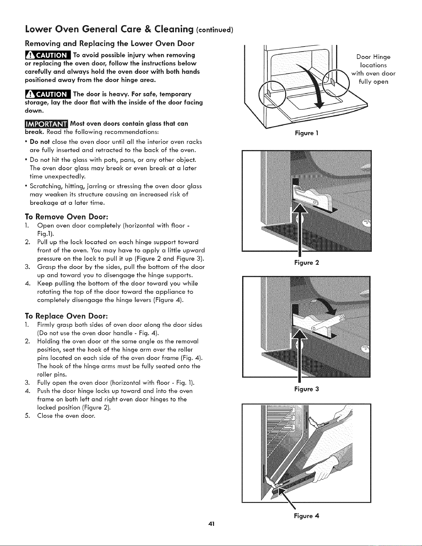
Lower Oven General Care & Cleaning (co.ti.ued)
Removing and Replacing the Lower Oven Door
To avoid possible injury when removing
or replacing the oven door, follow the instrucffans below
carefully and always hold the oven door with bath hands
pasltlaned away from the door hinge area.
The door is heavy. For safe,
temporary
storage, lay the door flat wlth the inside of the door facing
down.
Most oven doors con|aln glass thai can
break. Read the following recommendations:
° Do not close the oven door until all the interior oven racks
are fully inserted and retracted to the back of the oven.
° Do not hit the glass with pots, pans, or any other object.
The oven door glass may break or even break at a later
time unexpectedly.
° Scratching, hitting, jarring or stressing the oven door glass
may weaken its structure causing an increased risk of
breakage at a later time.
To Remove Oven Door:
l. Open oven door completely (horizontal with floor =
Fig.l).
2. Pull up the lock located on each hinge support toward
front of the oven. You may have to apply a little upward
pressure on the lock to pull it up (Figure 2 and Figure 3).
3. Grasp the door by the sides, pull the bottom of the door
up and toward you to disengage the hinge supports.
4. Keep pulling the bottom of the door toward you while
rotating the top of the door toward the appliance to
completely disengage the hinge levers (Figure 4).
To Replace Oven Door:
1. Firmly grasp both sides of oven door along the door sides
(Do not use the oven door handle - Fig. 4).
2. Holding the oven door at the same angle as the removal
position, seat the hook of the hinge arm over the roller
pins located on each side of the oven door frame (Fig. 4).
The hook of the hinge arms must be fully seated onto the
roller pins.
3. Fully open the oven door (horizontal with floor - Fig. 1).
4. Push the door hinge locks up toward and into the oven
frame on both left and right oven door hinges to the
locked position (Figure 2).
5. Close the oven door.
Figure |
Figure 2
Figure 3
Door Hinge
locations
with oven door
fully open
Figure 4
41
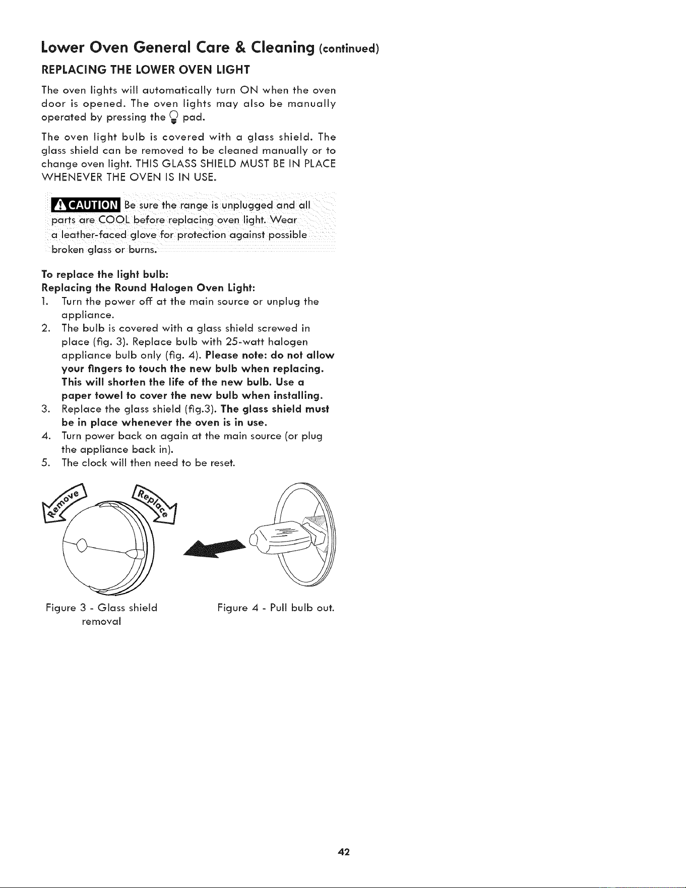
Lower Oven General Care & Cleaning (continued)
REPLACING THE LOWER OVEN LIGHT
The oven lights will automatically turn ON when the oven
door is opened. The oven lights may also be manually
operated by pressing the _ pad.
The oven light bulb is covered with a glass shield. The
glass shield can be removed to be cleaned manually or to
change oven light. THIS GLASS SHIELD MUST BE IN PLACE
WHENEVER THE OVEN IS IN USE.
Be sure the rancje is unplugcjed and all
parts are COOL before replacing oyen light. Wear
a leather_faced gl0Ye for pr0teCfion against
broken glass or burns,
To replace the light bulb:
Replacing the Round Halogen Oven Light:
1. Turn the power off: at the main source or unplug the
appliance.
2. The bulb is covered with a glass shield screwed in
place (fig. 3). Replace bulb with 25-watt halogen
appliance bulb only (fig. 4). Please note: do not allow
your fingers to touch the new bulb when replacing.
This will shorten the llfe of the new bulb. Use a
paper towel to cover the new bulb when installing.
3. Replace the glass shield (fig.3). The glass shield must
be in place whenever the oven is in use.
4. Turn power back on again at the main source (or plug
the appliance back in).
5. The clock will then need to be reset.
Figure 3 - Glass shield Figure 4 - Pull bulb out.
removaJ
42
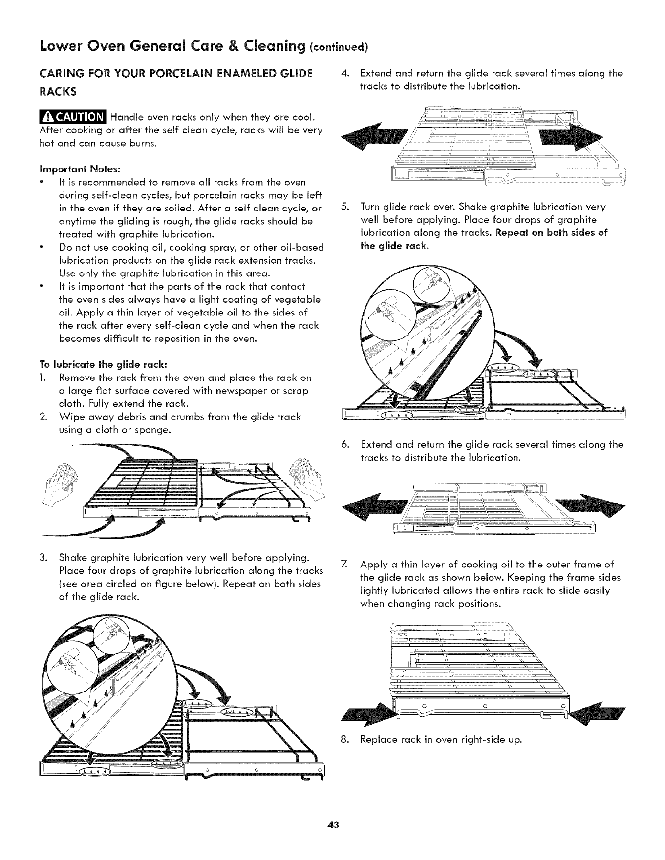
Lower Oven General Care & Cleaning (conti.uea)
CARING FOR YOUR PORCELAIN ENAMELED GLIDE
RACKS
4. Extend and return the glide rack several times along the
tracks to distribute the lubrication.
F_'_ Handle oven racks only when they are coot.
After cooking or after the self clean cycle, racks wiii be very
hot and can cause burns.
Important Notes:
° It is recommended to remove aii racks from the oven
during self-clean cycles, but porcelain racks may be left
in the oven if they are soiled. After a self clean cycle, or
anytime the gliding is rough, the glide racks should be
treated with graphite lubrication.
° Do not use cooking oil, cooking spray, or other oil-based
lubrication products on the glide rack extension tracks.
Use only the graphite lubrication in this area.
° It is important that the parts of the rack that contact
the oven sides always have a light coating of vegetable
oil. Apply a thin layer of vegetable oil to the sides of
the rack after every self-clean cycle and when the rack
becomes difficult to reposition in the oven.
To lubricate the gllde rack:
1. Remove the rack from the oven and place the rack on
a large fiat surface covered with newspaper or scrap
cloth. Fully extend the rack.
2. Wipe away debris and crumbs from the glide track
using a cloth or sponge.
.
6.
Turn glide rack over. Shake graphite lubrication very
well before applying. Place four drops of graphite
lubrication along the tracks. Repeat on bath sides of
the gllde rack.
Extend and return the glide rack several times along the
tracks to distribute the lubrication.
.
Shake graphite lubrication very well before applying.
Place four drops of graphite lubrication along the tracks
(see area circled on figure below). Repeat on both sides
of the glide rack.
7.
Apply a thin layer of cooking oil to the outer frame of
the glide rack as shown below. Keeping the frame sides
lightly lubricated allows the entire rack to slide easily
when changing rack positions.
8. Replace rack in oven right-side up.
43
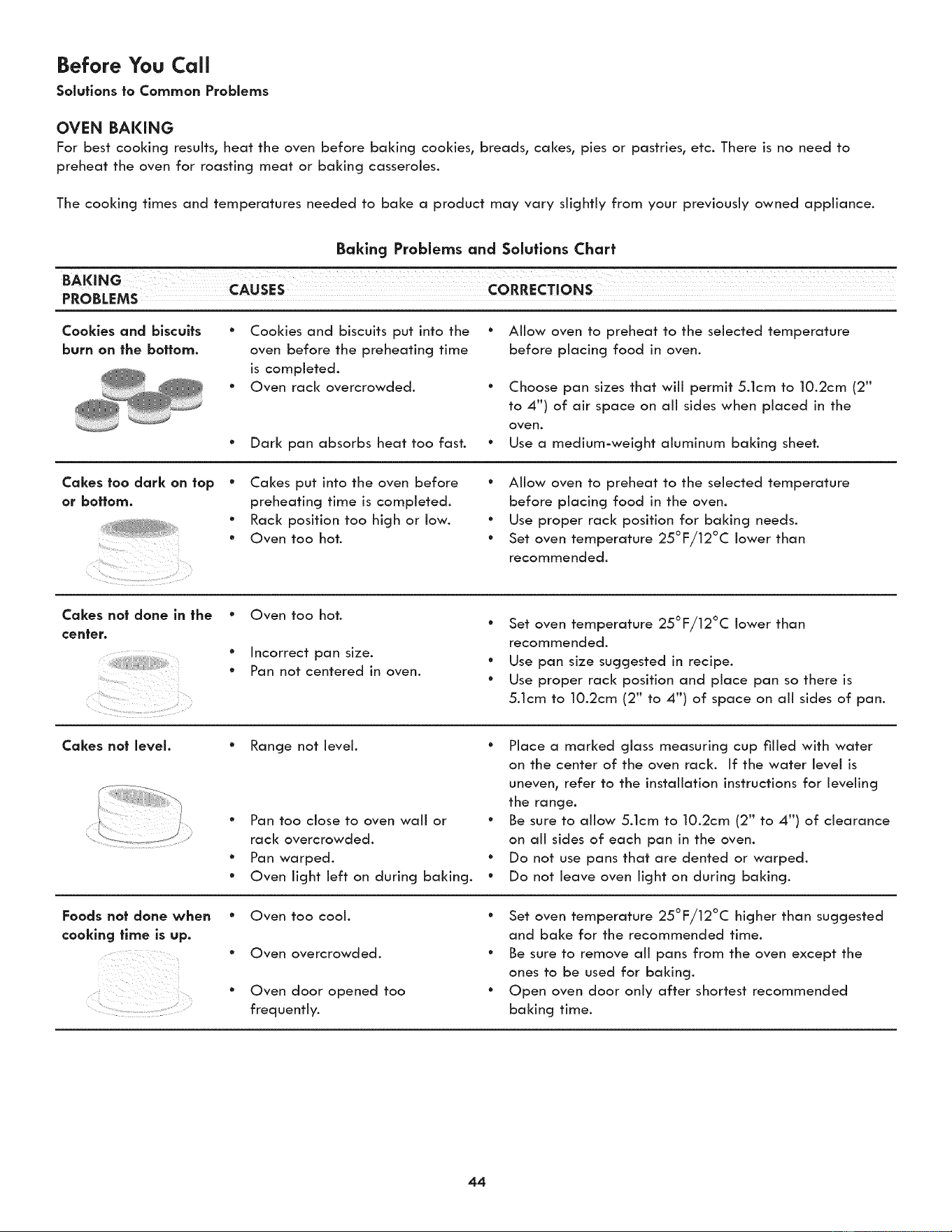
Before You Call
Solutions to Common Problems
OVEN BAKING
For best cooking results, heat the oven before baking cookies, breads, cakes, pies or pastries, etc. There is no need to
preheat the oven for roasting meat or baking casseroles.
The cooking times and temperatures needed to bake a product may vary slightly from your previously owned appliance.
Baking Problems and Solutions Chart
T
BAKING CAusES
PROBLEMS
Cookies and biscuits
burn on the bottom.
* Cookies and biscuits put into the
oven before the preheating time
is completed.
* Oven rack overcrowded.
° Dark pan absorbs heat too fast.
° Allow oven to preheat to the selected temperature
before placing food in oven.
° Choose pan sizes that will permit 5.1cm to 10.2cm (2"
to 4") of air space on all sides when placed in the
oven.
* Use a medium-weight aluminum baking sheet.
Cakes too dark on top
or bottom.
" Cakes put into the oven before
preheating time is completed.
• Rack position too high or low.
• Oven too hot.
• Allow oven to preheat to the selected temperature
before placing food in the oven.
• Use proper rack position for baking needs.
° Set oven temperature 25°F/12°C lower than
recommended.
Cakes not done in the
center.
¸¸%,¸¸¸¸.¸.
i i :
• Oven too hot.
• Incorrect pan size.
• Pan not centered in oven.
" Set oven temperature 25°F/12°C lower than
recommended.
* Use pan size suggested in recipe.
° Use proper rack position and place pan so there is
5.1cm to 10.2cm (2" to 4") of space on all sides of pan.
Cakes not level.
Foods not done when
cooking |line is up.
Range not level.
" Pan too close to oven wall or
rack overcrowded.
* Pan warped.
* Oven light left on during baking.
" Place a marked glass measuring cup filled with water
on the center of the oven rack. If the water level is
uneven, refer to the installation instructions for leveling
the range.
° Be sure to allow 5.1cm to 10.2cm (2" to 4") of clearance
on all sides of each pan in the oven.
° Do not use pans that are dented or warped.
° Do not leave oven light on during baking.
" Oven too cool.
" Oven overcrowded.
° Oven door opened too
frequently.
" Set oven temperature 25°F/12°C higher than suggested
and bake for the recommended time.
° Be sure to remove all pans from the oven except the
ones to be used for baking.
° Open oven door only after shortest recommended
baking time.
44
Before You Call (co.ti.ued)
Solutions to Common Problems
Before you call for service, review this list. It may save you time and expense. The list includes common occurrences that are
not the result of defective workmanship or materials in this appliance.
OCCURRENCE POSSIBLE CAUSE/SOLUTION
Control pads for Sensor Cooking, One-
* The oven door was opened and closed without initiating a cooking cycle within
Touch Cooking, and Defrost will not
three minutes. Touch Stop to resume normal pad operation.
operate.
Microwave oven light does not come
• If one of those situation appear please check the electrical outlet, fuse and/or
on. Cooling fan does not work.
circuit breaker. If they are functioning properly, contact Sears Part & Repair. A
Turntable does not rotate. Water in o
microwave oven should never be serviced by a "do-it-yourself" repair person.
cup in microwave does not warm.
A fan always comes on when I use my ° This is normal. This appliance is equipped with a blower which keeps aii internal
microwave oven components at a cool temperature. The blower may keep running even if the
oven has been turned off, until the components have cooled down.
Faulty Instollatlon ° Place oven rack in center of oven. Place a level on the oven rack. Contact
installing agent if rack and cabinet cutout flooring are not level.
Entire appllonce does not
operate
° Kitchen cabinet misaiignment may make oven appear to be not level. Be sure
cabinets are square and level. Contact cabinet maker to correct problem.
° The time of day is not set. The time of day must first be set in order to operate
the oven. See "Setting clock at power up" in the Getting Started section.
Oven does not operate
Oven light does not work
e
e
e
e
e
After self=cleanlng cycle, the fan •
seems to run forever
Be sure electrical cord is securely connected into the electrical junction box.
Cord/plug is not installed and/or connected. Cord is not supplied with oven.
Contact your dealer, installing agent or authorized servicer.
Service wiring is not complete. Contact your dealer, installing agent or
authorized service agent.
Electrical power outage. Check house lights to be sure. Call your local electric
company for service.
Short in cord/plug. Replace cord/plug.
Controls are not set properly. See instructions to set the controls.
House fuse has blown or circuit breaker has tripped immediately following
installation.
° House fuse may not be fully engaged. Check fuse and screw or engage circuit
breaker securely.
° Be sure the oven controls are set properly for the desired cooking feature.
See Lower Oven Operating Instructions in this Use & Care Guide or read the
instructions "Entire appliance does not operate" in this checldist.
° Replace or tighten bulb. See Changing Lower Oven Light section in this Use &
Care Guide.
Electrical power outage. Check house lights to be sure. Call your local electric
company for service.
After the self-cleaning cycle the fans will run until the oven cools down to an
acceptable temperature.
45
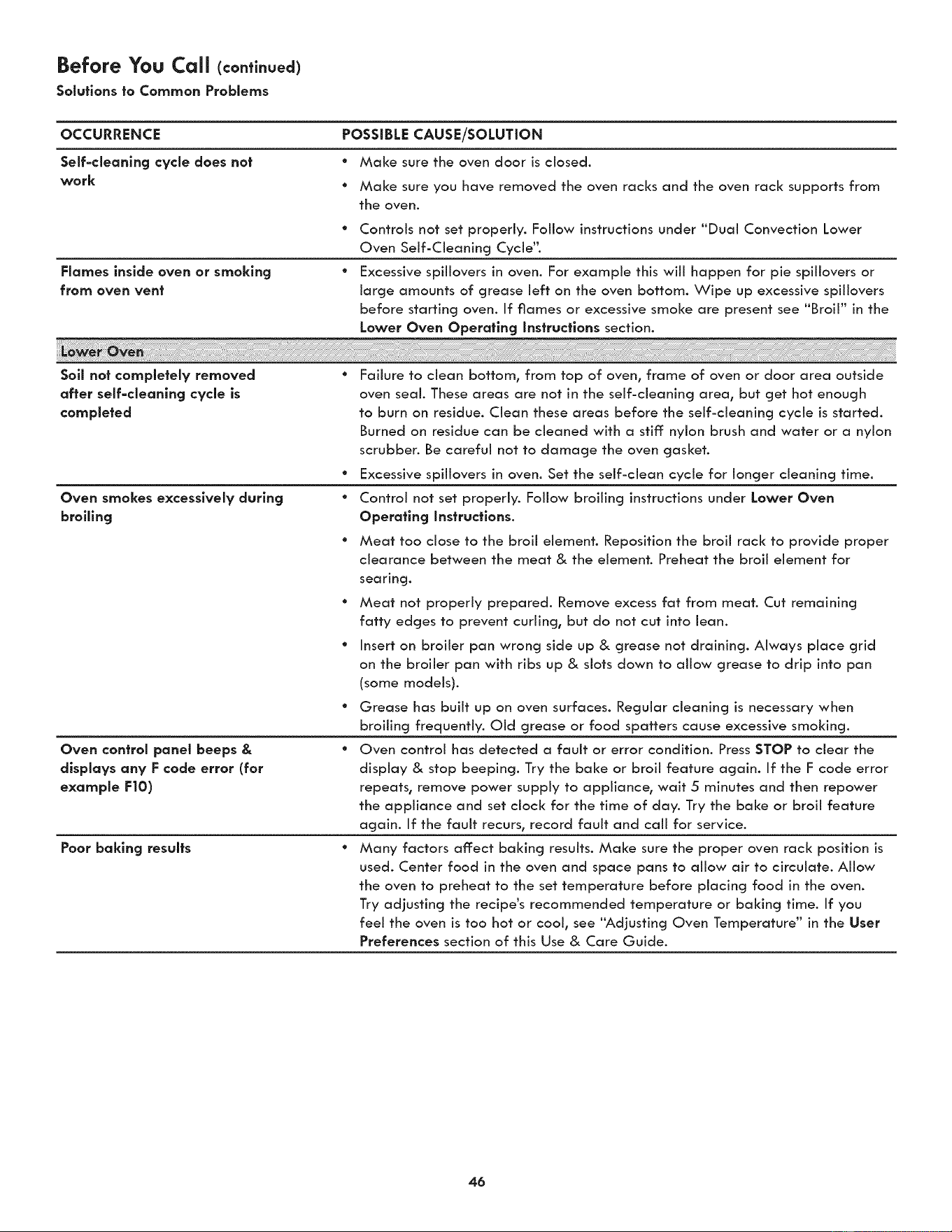
Before You CaJJ(contlnuea)
Soluflons to Common Problems
OCCURRENCE POSSIBLE CAUSE/SOLUTION
Self-cleanlng cycle does not
work
° Make sure the oven door is closed.
° Make sure you have removed the oven racks and the oven rack supports from
the oven.
° Controls not set properly. Follow instructions under "Dual Convection Lower
Oven Self-Cleaning Cycie'L
Flames inside oven or smoking ° Excessive spillovers in oven. For example this will happen for pie spillovers or
from oven vent large amounts of grease left on the oven bottom. Wipe up excessive spillovers
before starting oven. If flames or excessive smoke are present see "Broil" in the
Lower Oven Operating instructions section.
Soll not completely removed
after self-cleanlng cycle is
completed
Oven smokes excessively during
broiling
Oven control panel beeps &
displays any F code error (for
example F|O)
Poor baking results
° Failure to clean bottom, from top of oven, frame of oven or door area outside
oven seal. These areas are not in the self-cleaning area, but get hot enough
to burn on residue. Clean these areas before the self-cleaning cycle is started.
Burned on residue can be cleaned with a stiff: nylon brush and water or a nylon
scrubber. Be careful not to damage the oven gasket.
° Excessive spillovers in oven. Set the self-clean cycle for longer cleaning time.
° Control not set properly. Follow broiling instructions under Lower Oven
Operating Jnstructlons.
° Meat too dose to the broil element. Reposition the broil rack to provide proper
clearance between the meat & the element. Preheat the broil element for
searing.
° Meat not properly prepared. Remove excess fat from meat. Cut remaining
fatty edges to prevent curling, but do not cut into lean.
° Insert on broiler pan wrong side up & grease not draining. Always place grid
on the broiler pan with ribs up & slots down to allow grease to drip into pan
(some models).
* Grease has built up on oven surfaces. ReguJar cleaning is necessary when
broiling frequentiy. Old grease or food spatters cause excessive smoking.
* Oven control has detected a fault or error condition. Press STOP to clear the
dispJay & stop beeping. Try the bake or broil feature again. If the F code error
repeats, remove power suppJy to appJiance, wait 5 minutes and then repower
the appiiance and set clock for the time of day. Try the bake or broil feature
again. If the fauit recurs, record fauit and caii for service.
* Many factors affect baking resuits. Make sure the proper oven rack position is
used. Center food in the oven and space pans to allow air to circulate. Allow
the oven to preheat to the set temperature before pJacing food in the oven.
Try adjusting the recipe's recommended temperature or baking time. If you
feel the oven is too hot or cool, see "Adjusting Oven Temperature" in the User
Preferences section of this Use & Care Guide.
46
MASTER PROTECTION AGREEMENTS
Congratulations on making a smart purchase. Your new Kenmore _ product is designed and manufactured for years of
dependable operation. But like all products, it may require preventive maintenance or repair from time to time. That's when
having a Master Protection Agreement can save you money and aggravation.
The Master Protection Agreement also helps extend the life of your new product. Here's what the Agreement* includes:
[] Parts and labor needed to help keep products operating properly under normal use, not just defects. Our coverage
goes well beyond the product warranty. No deductibles, no functional failure excluded from coverage - real
protection.
[] Expert service by a force of more than 10,000 authorized Sears service technicians, which means someone you
can trust will be working on your product.
[] Unlimited service calls and nationwide service, as often as you want us, whenever you want us.
[] <<No-lemon>>guarantee - replacement of your covered product if four or more product failures occur within twelve
months.
[] Product replacement if your covered product can't be fixed.
[] Annual Preventive Maintenance Check at your request - no extra charge.
[] Fast help by phone - we call it Rapid Resolution - phone support from a Sears representative on all products.
Think of us as a ,<talking owner's manual_,.
[] Power surge protection against electrical damage due to power fluctuations.
[] $250 Food Loss Protection annually for any food spoilage that is the result of mechanical failure of any covered
refrigerator or freezer.
[] Rental reimbursement if repair of your covered product takes longer than promised.
[] 25% discount off the regular price of any non-covered repair service and related installed parts.
Once you purchase the Agreement, a simple phone call is all that it takes for you to schedule service. You can call anytime
day or night, or schedule a service appointment online.
The Master Protection Agreement is a risk free purchase. If you cancel for any reason during the product warranty period,
we will provide a full refund. Or, a prorated refund anytime after the product warranty period expires. Purchase your Master
Protection Agreement today!
Some limitations and exclusions apply. For prices and additional information in the U.S.A. call 1-800-827-6655.
* Coverage in Canada varies on some items. For full details call Sears Canada at 1-800-361-6665.
Sears Installation Service
For Sears professional installation of home appliances, garage door openers, water heaters, and other major home items,
in the U.S.A. or Canada call 1-800-4-MY-HOME%

For Sears Home Services in-home repair
of all Kenmore major appliances.
For the replacement parts, accessories and
Use & Care Guides that you need to do-it-yourself.
For professional installation of major home appliances
and items like air conditioners and water heaters.
44-553-6667
www.kenmore.com
In Canada 1-800-469-4663
W W W. Se a r s. c a ...............................
Call anytime for the location of your nearest
i_i':i: SearsParts& Repa,rServ,ceCenter
_'!; 1-800-488-1222 (U.S.A.) 1-800-469-4663 (Canada)
ii_!i To purchase a protection agreement on a serviceable product:
-8oo-82z-6655 -8oo-36 -6665c ooo o)
Para pedir servicio de reparaci6n Au Canada pour service en fran£:ais:
odom_c_l_o,vordeoo_p_ezo_: 1-800-LE-FOYER_
_i;_;: ,_888_SU_HOGAR® (,_SwOOw5s_3;6937)
www.kenmore.com