(1,1)
北米Model "A1700BE-B" EDITED: 2017/ 9/ 12
Foreword
Foreword
SFWAA
Congratulations on choosing a SUBARU vehicle. This Owner’s
Manual has all the information necessary to keep your SUBARU in
excellent condition and to properly maintain the emission control
system for minimizing emission pollutants. We urge you to read this
manual carefully so that you may understand your vehicle and its
operation. For information not found in this Owner’s Manual, such
as details concerning repairs or adjustments, please contact the
SUBARU dealer from whom you purchased your SUBARU or the
nearest SUBARU dealer.
The information, specifications and illustrations found in this
manual are those in effect at the time of printing. SUBARU
CORPORATION reserves the right to change specifications and
designs at any time without prior notice and without incurring any
obligation to make the same or similar changes on vehicles
previously sold. This Owner’s Manual applies to all models and
covers all equipment, including factory installed options. Some
explanations, therefore may be for equipment not installed in your
vehicle.
Please leave this manual in the vehicle at the time of resale. The next
owner will need the information found herein.
SUBARU CORPORATION, TOKYO, JAPAN
is a registered trademark of SUBARU CORPORATION.
*
C
Copyright 2017 SUBARU CORPORATION
(2,1)
北米Model "A1700BE-B" EDITED: 2017/ 9/ 12
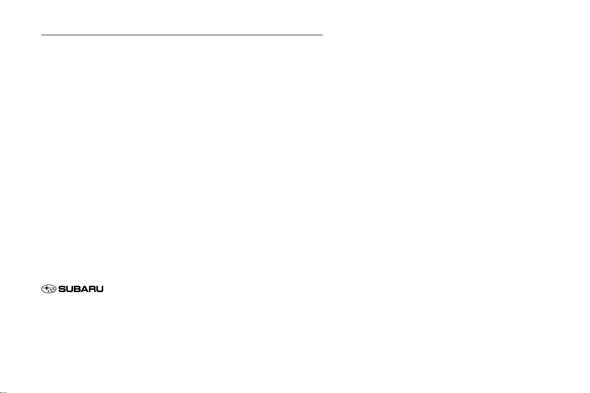
This manual describes the following vehicle types.
1) STI except TYPE RA
2) TYPE RA
3) Other models

Black plate (3,1)
Model "ALL_MODEL_MEMO" EDITED: 2007/ 6/ 22

(3,1)
北米Model "A1700BE-B" EDITED: 2017/ 10/ 11
Warranties
& Warranties for U.S.A.
All SUBARU vehicles distributed by
Subaru of America, Inc. and sold at retail
by an authorized SUBARU dealer in the
United States come with the following
warranties:
. SUBARU Limited Warranty
. Emission Control Systems Warranty
. Emissions Performance Warranty
All warranty information, including details
of coverage and exclusi ons, is in t he
“Warranty and Maintenance B ooklet”.
Read these warranties carefully.
& Warranties for Canada
All SUBARU vehicles distributed by
Subaru Canada, Inc. and sold at retail by
an authorized SUBARU dealer in Canada
come with the following warranties:
. SUBARU Limited Warranty
. Anti-Corrosion Warranty
. Emission Control Warranty
All warranty information, including details
of coverage and exclusi ons, is in t he
“Warranty and Service Booklet”.Read
these warranties carefully.
& Warranties except for U.S.A.
and Canada
All warranty information, including details
of coverage and exclusions, is in the
“Warranty and Maintenance Booklet”.
Read these warranties carefully.
Important information for
TYPE RA
The steering wheel is covered in ultra-
suede. In order to maintain the character-
istic texture and appearance of ultra-
suede, regular cleaning of the steering
wheel is recommended. For the mainte-
nance procedures, refer to “Steering
wheel with ultra-suede covering” F10-7.
1
0

(4,1)
北米Model "A1700BE-B" EDITED: 2017/ 10/ 11
How to use this Owner’s
Manual
& Using your Owner’s Manual
Before you operate your vehicle, carefully
read this manual. To protect yourself and
extend the service life of your vehicle,
follow the instructions in this manual.
Failure to observe these instructions may
result in serious injury and damage to your
vehicle.
This manual is composed of fourteen
chapters. Each chapter begins with a brief
table of contents, so you can usually tell at
a glance if that chapter contains the
information you want.
Chapter 1: Seat, seatbelt and SRS air-
bags
This chapter informs you how to use the
seat and seatbelt and contains precau-
tions for the SRS airbags.
Chapter 2: Keys and doors
This chapter informs you how to operate
the keys, locks and windows.
Chapter 3: Instruments and controls
This chapter informs you about the opera-
tion of instrument panel indicators and how
to use the instruments and other switches.
Chapter 4: Climate control
This chapter informs you how to operate
the climate control.
Chapter 5: Audio
This chapter informs you how to operate
your audio system.
Chapter 6: Interior equipment
This chapter informs you how to operate
interior equipment.
Chapter 7: Starting and operating
This chapter informs you how to start and
operate your SUBARU.
Chapter 8: Driving tips
This chapter informs you how to drive your
SUBARU in various conditions and ex-
plains some safety tips on driving.
Chapter 9: In case of emergency
This chapter informs you what to do if you
have a problem, such as a flat tire or
engine overheating.
Chapter 10: Appearance care
This chapter informs you how to keep your
SUBARU looking good.
Chapter 11: Maintenance and service
This chapter informs you when you need to
take your SUBARU to the dealer for
scheduled maintenance and informs you
how to keep your SUBARU running
properly.
Chapter 12: Specifications
This chapter informs you about dimen-
sions and capacities of your SUBARU.
Chapter 13: Consumer information and
Reporting safety defects
This chapter informs you about Uniform
tire quality grading standards and Report-
ing safety defects.
Chapter 14: Index
This is an alphabetical listing of all that’sin
this manual. You can use it to quickly find
something you want to read.
For models with the EyeSight system:
For details about the EyeSight system,
refer to the Owner’s Manual supplement
for the EyeSight system.
& Safety warnings
You will find a number of WARNINGs,
CAUTIONs and NOTEs in this manual.
These safety warnings alert you to poten-
tial hazards that could result in injury to you
or others.
Please read these safety warnings as well
as all other portions of this manual care-
fully in order to gain a better understanding
of how to use your SUBARU vehicle safely.
2
(5,1)
北米Model "A1700BE-B" EDITED: 2017/ 10/ 11
WARNING
A WARNING indicates a situation in
which serious injury or death could
result if the warning is ignored.
CAUTION
A CAUTION indicates a situation in
which injury or damage to your
vehicle, or both, could result if the
caution is ignored.
NOTE
A NOTE gives information or sugges-
tions how to make better use of your
vehicle.
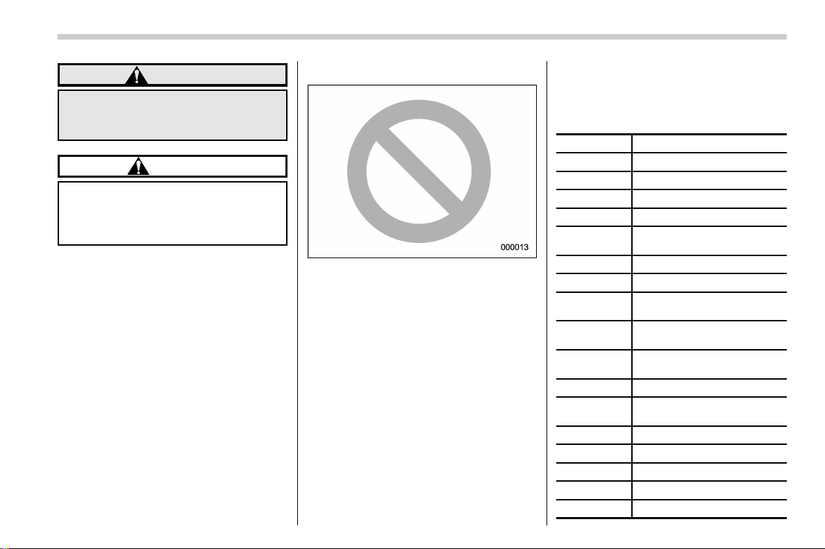
& Safety symbol
You will find a circle with a slash through it
in this manual. This symbol means “Do
not”, “Do not do this”,or“Do not let this
happen”, depending upon the context.
& Abbreviation list
You may find several abbreviations in this
manual. The meanings of the abbrevia-
tions are shown in the following list.
Abbreviation Meaning
A/C Air conditioner
ABS Anti-lock brake system
AKI Anti knock index
ALR Automatic locking retractor
ALR/ELR
Automatic locking retractor/
Emergency locking retractor
AVH Auto Vehicle Hold
AWD All-wheel drive
BSD/RCTA
Blind Spot Detection/Rear
Cross Traffic Alert
CVT
Continuously variable trans-
mission
C.DIFF/
DCCD
Driver’s control center differ-
ential
DRL Daytime running light
EBD
Electronic brake force distri-
bution
ELR Emergency locking retractor
GAW Gross axle weight
GAWR Gross axle weight rating
GPS Global positioning system
GVW Gross vehicle weight
– CONTINUED –
3
0
(6,1)
北米Model "A1700BE-B" EDITED: 2017/ 10/ 11
Abbreviation Meaning
GVWR Gross vehicle weight rating
INT Intermittent
LATCH
Lower anchors and tethers for
children
LED Light emitting diode
LSD Limited slip differential
MIL Malfunction indicator light
MMT
Methylcyclopentadienyl man-
ganese tricarbonyl
MT Manual transmission
OBD On-board diagnostics
RAB Reverse Automatic Braking
RON Research octane number
SI-DRIVE SUBARU Intelligent Drive
SRH
Steering Responsive Head-
light
SRS
Supplemental restraint sys-
tem
TIN Tire identification number
TPMS
Tire pressure monitoring sys-
tem
Vehicle symbols
These are some of the symbols you may
see on your vehicle.
For warning and indicator lights, refer to
“Warning and indicator lights” F25.
Mark Name
WARNING
CAUTION
Safety precautions when
driving
& Seatbelt and SRS airbag
WARNING
. All persons in the vehicle must
fasten their seatbelts BEFORE
the vehicle starts to move. Other-
wise, the possibility of serious
injury becomes greater in the
event of a sudden stop or acci-
dent.
. To obtain maximum protection in
the event of an accident, the
driver and all passengers must
always wear seatbelts when in
the vehicle. The SRS (Supple-
mental Restraint System) airbag
does not do away with the need to
fasten seatbelts. In combination
with the seatbelts, it offers the
best combined protection in case
of a serious accident.
Not wearing a seatbelt increases
the chance of severe injury or
death in a crash even when the
vehicle has the SRS airbag.
4
(7,1)
北米Model "A1700BE-B" EDITED: 2017/ 10/ 11
. The SRS airbags deploy with
considerable speed and force.
Occupants who are out of proper
position when the SRS airbag
deploys could suffer very serious
injuries. Because the SRS airbag
needs enough space for deploy-
ment, the driver should always sit
upright and well back in the seat
as far from the steering wheel as
practical while still maintaining
full vehicle control and the front
passenger should move the seat
as far back as possible and sit
upright and well back in the seat.
For instructions and precautions, carefully
read the following sections.
. For the seatbelt system, refer to “Seat-
belts” F1-12.
. For the SRS airbag system, refer to
“*SRS airbag (Supplemental Restraint
System airbag)” F1-33.
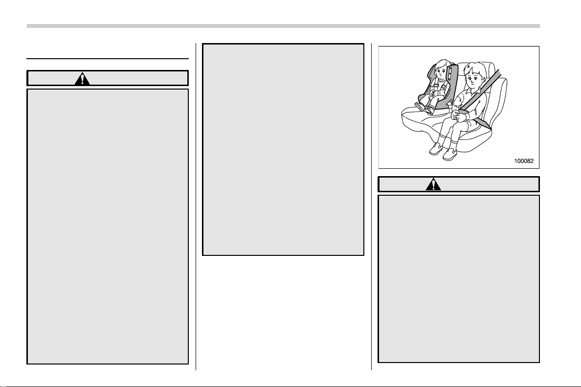
& Child safety
WARNING
. Never hold a child on your lap or
in your arms while the vehicle is
moving. The passenger cannot
protect the child from injury in a
collision, because the child will
be caught between the passen-
ger and objects inside the vehi-
cle.
. While riding in the vehicle, infants
and small children should always
be seated in the REAR seat in an
infant or child restraint system
which is appropriate for the
child’s age, height and weight. If
a child is too big for a child
restraint system, the child should
sit in the REAR seat and be
restrained using the seatbelts.
According to accident statistics,
children are safer when properly
restrained in the rear seating
positions than in the front seating
positions. Never allow a child to
stand up or kneel on the seat.
. Put children in the REAR seat
properly restrained at all times in
a child restraint device or in a
seatbelt. The SRS airbag deploys
with considerable speed and
force and can injure or even kill
children, especially if they are not
restrained or improperly re-
strained. Bec ause children are
lighter and weaker than adults,
their risk of being injured from
deployment is greater.
. NEVER INSTALL A FORWARD OR
REARWARD FACING CHILD
SEAT IN THE FRONT SEAT.
DOING SO RISKS SERIOUS IN-
JURY OR DEATH TO THE CHILD
BY PLACING THE CHILD’S HEAD
TOO CLOSE TO THE SRS AIR-
BAG.
. Always turn the child safety locks
to the “LOCK” position when
children sit in the rear seat.
Serious injury could result if a
child accidentally opens the door
and falls out. Refer to “Ch ild
safety locks” F2-31.
. Always lock the passenger’s win-
dows using the lock switch when
children are riding in the vehicle.
Failure to follow this procedure
could result in injury to a child
operating the power window. Re-
fer to “Windows” F2-31.
. Never leave unattended children,
– CONTINUED –
5
0
(8,1)
北米Model "A1700BE-B" EDITED: 2017/ 10/ 11
adults or animals in the vehicle.
They could accidentally injure
themselves or others through
inadvertent operation of the ve-
hicle. Also, on hot or sunny days,
the temperature in a closed vehi-
cle could quickly become high
enough to cause severe or pos-
sibly fatal injuries.
. Help prevent children, adults or
animals from locking themselves
in the trunk. On hot or sunny
days, the temperature in the trunk
could quickly become high en-
ough to cause death or serious
heat-related injuries including
brain damage to anyone locked
inside, particularly for small chil-
dren.
. When leaving the vehicle, close
all windows and lock all doors.
Also make certain that the trunk
is closed.
For instructions and precautions, carefully
read the following sections.
. For the seatbelt system, refer to “Seat-
belts” F1-12.
. For the child restraint system, refer to
“Child restraint systems” F 1-21.
. For the SRS airbag system, refer to
“*SRS airbag (Supp lemen tal Restr aint
System airbag)” F1-33.
& Engine exhaust gas (carbon
monoxide)
WARNING
. Never inhale engine exhaust gas.
Engine exhaust gas contains
carbon monoxide, a colorless
and odorless gas which is dan-
gerous, or even lethal, if inhaled.
. Always properly maintain the en-
gine exhaust system to prevent
engine exhaust gas from entering
the vehicle.
. Never run the engine in a closed
space, such as a garage, except
for the brief time needed to drive
the vehicle in or out of it.
. Avoid remaining in a parked ve-
hicle for a lengthy time while the
engine is running. If that is un-
avoidable, then use the ventila-
tion fan to force fresh air into the
vehicle.
. Always keep the front ventilator
inlet grille free from snow, leaves
or other obstructions to ensure
that the ventilation system al-
ways works properly.
. If at any time you suspect that
exhaust fumes are entering the
vehicle, have the problem
checked and corrected as soon
as possible. If you must drive
under these condit ions, drive
only with all windows fully open.
. Keep the trunk lid closed while
driving to prevent exhaust gas
from entering the vehicle.
& Drinking and driving
WARNING
Drinking and then driving is very
dangerous. Alcohol in the blood-
stream delays your reaction time
and impairs your perception, judg-
ment and attentiveness. If you drive
after drinking – even if you drink just
a little – it will increase the risk of
being involved in a serious or fatal
accident, injuring or killing yourself,
your passengers and others. In
addition, if you are injured in the
accident, alcohol may increase the
severity of that injury.
Please don’t drink and drive.
6
(9,1)
北米Model "A1700BE-B" EDITED: 2017/ 10/ 11
Drunken driving is one of the most frequent
causes of accidents. Since alcohol affects
all people differently, you may have con-
sumed too much alcohol to drive safely
even if the level of alcohol in your blood is
below the legal limit. The safest thing you
can do is never drink and drive. However if
you have no choice but to drive, stop
drinking and sober up completely before
getting behind the wheel.
& Drugs and driving
WARNING
There are some drugs (over the
counter and prescription) that can
delay your reaction time and impair
your perception, judgment and at-
tentiveness. If you drive after taking
them, it may increase your, your
passengers’ and other persons’ risk
of being involved in a serious or fatal
accident.
If you are taking any drugs, check with
your doctor or pharmacist or read the
literature that accompanies the medication
to determine if the drug you are taking can
impair your driving ability. Do not drive
after taking any medications that can make
you drowsy or otherwise affect your ability
to safely operate a motor vehicle. If you
have a medical condition that requires you
to take drugs, please consult with your
doctor.
Never drive if you are under the influence
of any illicit mind-altering drugs. For your
own health and well-being, we urge you
not to take illegal drugs in the first place
and to seek treatment if you are addicted
to those drugs.
& Driving when tired or sleepy
WARNING
When you are tired or sleepy, your
reaction time will be delayed and
your perception, judgment and at-
tentiveness will be impaired. If you
drive when tired or sleepy, your,
your passengers’ and othe r per-
sons’ chances of being involved in
a serious accident may increase.
Please do not continue to drive but instead
find a safe place to rest if you are tired or
sleepy. On long trips, you should make
periodic rest stops to re fr esh yourself
before continuing on your journey. When
possible, you should share the driving with
others.
& Modification of your vehicle
CAUTION
Your vehicle should not be modified
other than with genuine SUBARU
parts and accessories. Other types
of modifications could affect its
performance, safety or durability,
and may even violate governmental
regulations. In addition, damage or
performance problems resulting
from modification may not be cov-
ered under warranties.
NOTE
This vehicle is equipped with a function
that will record certain vehicle data in
the event the vehicle is operated or
maintained in a manner that exceeds or
varies from routine normal use.
That data may be used as a means of
determining whether or not a vehicle
condition is eligible for repair under
warranty.
– CONTINUED –
7
0
(10,1)
北米Model "A1700BE-B" EDITED: 2017/ 10/ 11
& Car phone/cell phone and
driving
CAUTION
Do not use a car phone/cell phone
while driving; it may distract your
attention from driving and can lead
to an accident. If you use a car
phone/cell phone, pull off the road
and park in a safe place before using
your phone. In some States/Pro-
vinces, only hands-free phones
may legally be used while driving.
& Driving vehicles equipped
with navigation system
WARNING
Do not allow the monitor to distract
your attention from driving. Also, do
not opera te the con trols of the
navigation system while driving.
The loss of attention to driving could
lead to an accident. If you wish to
operate the controls of the naviga-
tion system, first take the vehicle off
the road and stop it in a safe place.
& Driving with pets
Unrestrained pets can interfere with your
driving and distract your attention from
driving. In a collision or sudden stop,
unrestrained pets or cages can be thrown
around inside the vehicle and hurt you or
your passengers. Besides, the pets can be
hurt under these situations. It is also for
their own safety that p ets should be
properly restrained in your vehicle. Re-
strain a pet with a special traveling harness
which can be secured to the rear seat with
a seatbelt or use a pet carrier which can be
secured to the rear seat by routing a
seatbelt through the carrier’s handle.
Never restrain pets or pet carriers in the
front passenger’s seat. For further infor-
mation, consult your veterinarian, local
animal protection society or pet shop.
& Tire pressures
Check and, if necessary, adjust the pres-
sure of each tire (including the spare) at
least once a month and before any long
journey.
Check the tire pressure when the tires are
cold. Use a pressure gauge to adjust the
tire pressures to the values shown on the
tire placard. For detailed information, refer
to “Tires and wheels” F11-30.
WARNING
Driving at high speeds with exces-
sively low tire pressures can cause
the tires to deform severely and to
rapidly become hot. A sharp in-
crease in temperature could cause
tread separation, and destruction of
the tires. The resulting loss of vehi-
cle control could lead to an accident.
& Attaching accessories
WARNING
. Do not attach any accessories,
labels or stickers (other than
properly placed inspection stick-
ers) to the windshield . Such
items may obstruct your view.
. If it is necessary to attach an
accessory (such as an electronic
toll c ollection (ETC) device or
security pass) to the windshield,
consult your SUBARU dealer for
details on the proper location.
8
(11,1)
北米Model "A1700BE-B" EDITED: 2017/ 10/ 11
General information
& California proposition 65
warning
WARNING
Engine exhaust, some of its consti-
tuents, and certain vehicle compo-
nents contain or emit chemicals
known to the State of California to
cause cancer and birth defects or
other reproductive harm. In addi-
tion, certain fluids in vehicles and
certain components of product wear
contain or emit chemicals known to
the State of California to cause
cancer and birth defects or other
reproductive harm.
& California Perchlorate Advi-
sory
Certain vehicle components such as air-
bag modules, seatbelt pretensioners and
keyless entry transmitter batteries may
contain p erchlorate material. Special
handling may apply for service or vehicle
end of life disposal. See www.dtsc.ca.gov/
hazardouswaste/perchlorate.
& Noise from under the vehicle
NOTE
You may hear a noise from under the
vehicle approximately 5 to 10 hours
after the engine is turned off. However,
this does not indicate a malfunction.
This noise is caused by the operation of
the fuel evaporation leakage checking
system and the operation is normal.
The noise will stop after approximately
15 minutes.
& Event data recorder
This vehicle is equipped with an event data
recorder (EDR). The main purpose of an
EDR is to record, in certain crash or near
crash-like situations, such as an air bag
deployment or hitting a road obstacle, data
that will assist in understanding how a
vehicle’s systems performed. The EDR is
designed to record data related to vehicle
dynamics and safety systems for a short
period of time, typically 30 seconds or less.
The EDR in this vehicle is designed to
record such data as:
. How various systems in your vehicle
were operating;
. Whether or not the driver and passen-
ger safety belts were buckled/fastened;
. Howfar(ifatall)thedriverwas
depressing the accelerator and/or brake
pedal; and,
. How fast the vehicle was traveling.
These data can help provide a better
understanding of the circumstances in
which crashes and injuries occur. NOTE:
EDR data are recorded by your vehicle
only if a non-trivial crash situation occurs;
no data are recorded by the EDR under
normal driving conditions and no personal
data (e.g., name, gender, age, and crash
location) are recorded. However, other
parties, such as law enforcement, could
combine the EDR data with the type of
personally identifying data routinely ac-
quired during a crash investigation.
To read data recorded by an EDR, special
equipment is required, and access to the
vehicle or the EDR is needed. In addition
to the vehicle manufacturer, other parties,
such as law enforcement, that have the
special equipment, can read the informa-
tion if they have access to the vehicle or
the EDR.
9
0

Black plate (2,1)
Model "ALL_MODEL_MEMO" EDITED: 2007/ 6/ 22
Left Page
————————————————————————————————————————
————————————————————————————————————————
————————————————————————————————————————
————————————————————————————————————————
————————————————————————————————————————
————————————————————————————————————————
————————————————————————————————————————
————————————————————————————————————————
————————————————————————————————————————
————————————————————————————————————————
————————————————————————————————————————
————————————————————————————————————————
————————————————————————————————————————

(1,1)
北米Model "A1700BE-B" EDITED: 2017/ 10/ 11
Table of contents
Seat, seatbelt and SRS airbags
1
Keys and doors
2
Instruments and controls
Climate control
4
Audio
5
Interior equipment
6
Starting and operating
7
Driving tips
8
In case of emergency
9
Appearance care
10
Maintenance and service
11
Specifications
12
Consumer information and Reporting safety defects
13
Index
14
3
(14,1)
北米Model "A1700BE-B" EDITED: 2017/ 10/ 11
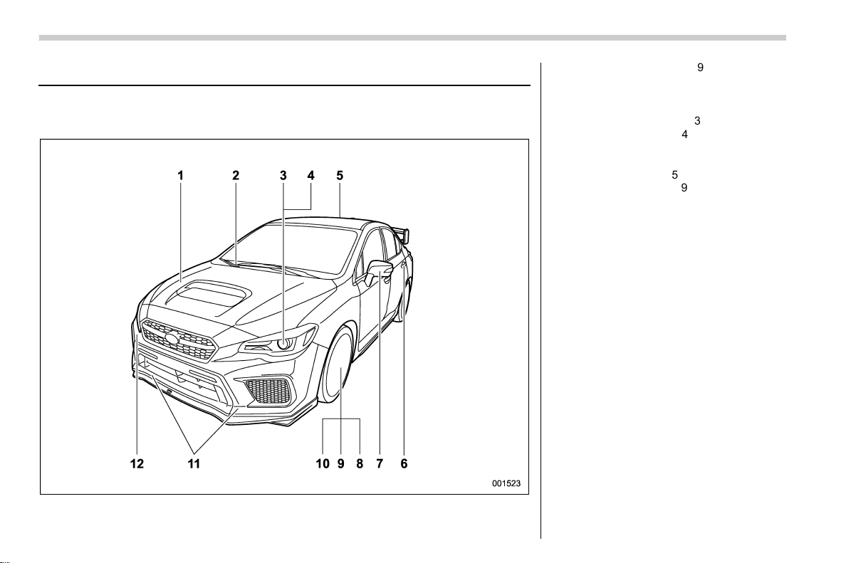
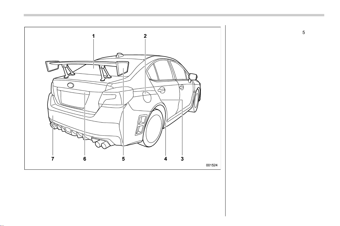
Illustrated index
& Exterior
! TYPE RA
1) Engine hood (page 11-9)
2) Front wiper (page 3-72)
3) Headlight (page 3-64)
4) Replacing bulbs (page 11-44)
5) Carbon roof (page 10-3)
6) Door locks (page 2-4)
7) Outside mirrors (page 3-83)
8) Tire pressure (page 11-32)
9) Flat tires (page 9-5)
10) Snow tires (page 8-9)
11) Tie-down hooks (page 9-21)
12) Towing hook (page 9-21)
12
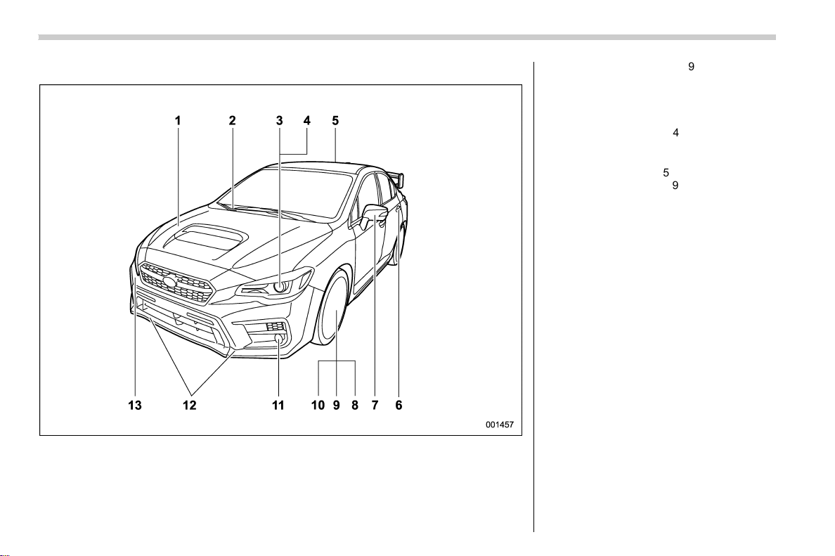
(16,1)
北米Model "A1700BE-B" EDITED: 2017/ 10/ 11
! Other models
1) Engine hood (page 11-9)
2) Front wiper (page 3-72)
3) Headlight (page 3-64)
4) Replacing bulbs (page 11-44)
5) Moonroof (page 2-38)
6) Door locks (page 2-4)
7) Outside mirrors (page 3-83)
8) Tire pressure (page 11-32)
9) Flat tires (page 9-5)
10) Snow tires (page 8-9)
11) Fog light (page 3-72)
12) Tie-down hooks (page 9-21)
13) Towing hook (page 9-21)
14

(18,1)
北米Model "A1700BE-B" EDITED: 2017/ 10/ 11
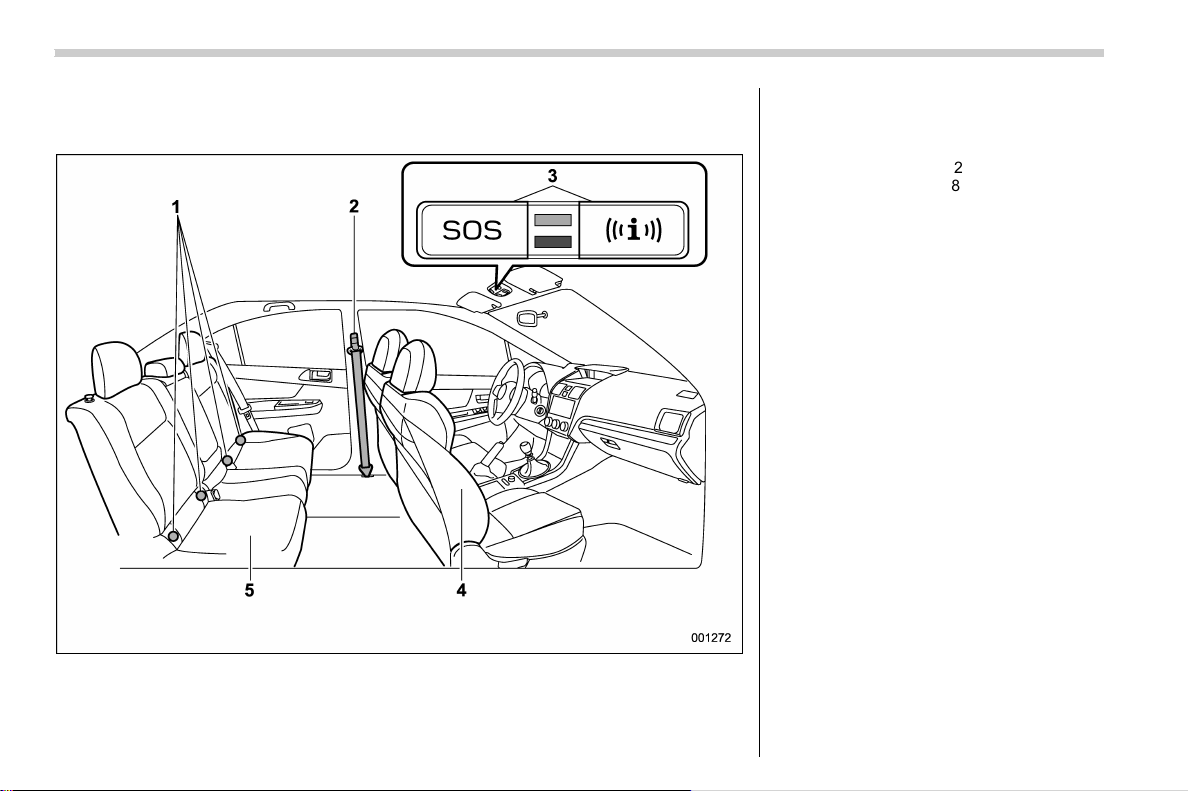
& Interior
! Passenger compartment area
1) Lower anchorages for child restraint
system (page 1-30)
2) Seatbelt (page 1-12)
3) Buttons for SUBARU STARLINK
4) Front seat (page 1-2)
5) Rear seat (page 1-8)
NOTE
For models with SUBARU STARLINK
(U.S.-spec. models only): Refer to the
Owner’ s Manual supplement for
SUBARU STARLINK.
16
(19,1)
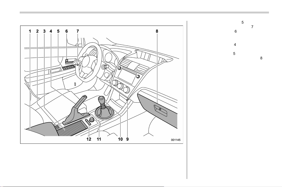
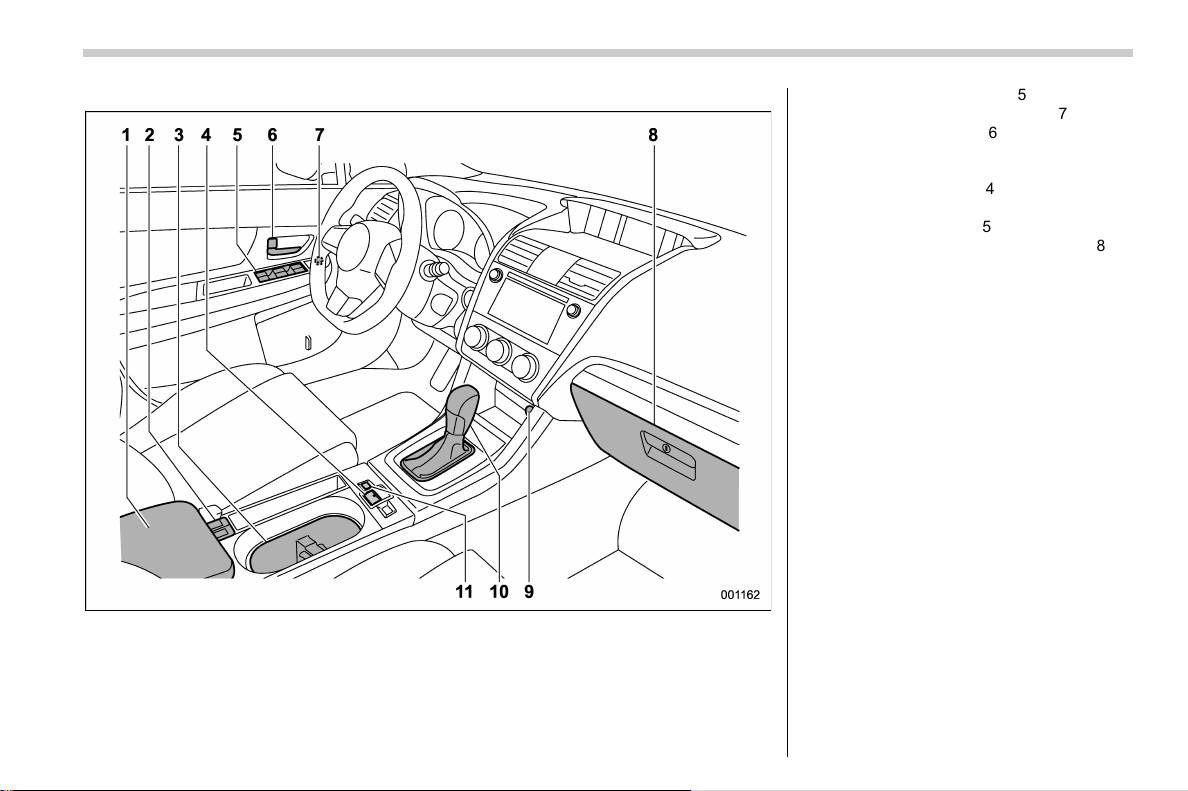
北米Model "A1700BE-B" EDITED: 2017/ 10/ 11
(STI)
1) Center console (page 6-5)
2) Seat heater switches (page 1-7)
3) Cup holder (page 6-6)
4) Parking brake lever (page 7-42)
5) Power window switches (page 2-31)
6) Door locks (page 2-4)
7) Outside mirror switch (page 3-83)
8) Glove box (page 6-5)
9) Front power supply socket (page 6-8)
10) Shift lever (page 7-16)
11) SI-DRIVE switches (page 7-28)
12) Driver’s Control Center Differential
(C.DIFF/DCCD) switches (page 7-18)
– CONTINUED –
17
0
(20,1)
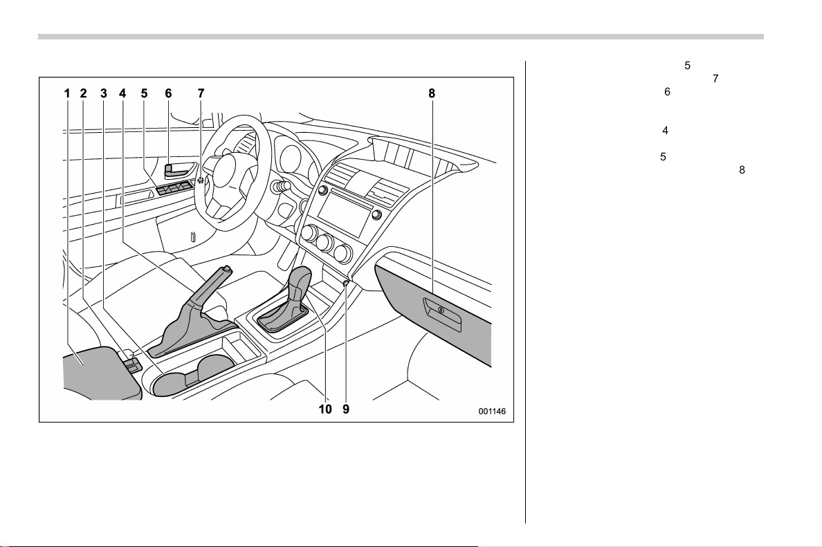
北米Model "A1700BE-B" EDITED: 2017/ 10/ 11
(Except STI) (models without the EyeSight system)
1) Center console (page 6-5)
2) Seat heater switches (page 1-7)
3) Cup holder (page 6-6)
4) Parking brake lever (page 7-42)
5) Power window switches (page 2-31)
6) Door locks (page 2-4)
7) Outside mirror switch (page 3-83)
8) Glove box (page 6-5)
9) Front power supply socket (page 6-8)
10) Shift lever (MT) (page 7-16)/Select lever
(CVT) (page 7-24)
18
(21,1)
北米Model "A1700BE-B" EDITED: 2017/ 10/ 11
(Except STI) (models with the EyeSight system)
1) Center console (page 6-5)
2) Seat heater switches (page 1-7)
3) Cup holder (page 6-6)
4) Parking brake switch (page 7-42)
5) Power window switches (page 2-31)
6) Door locks (page 2-4)
7) Outside mirror switch (page 3-83)
8) Glove box (page 6-5)
9) Front power supply socket (page 6-8)
10) Select lever (page 7-24)
11) Auto Vehicle Hold switch (page 7-47)
– CONTINUED –
19
0
(22,1)
北米Model "A1700BE-B" EDITED: 2017/ 10/ 11
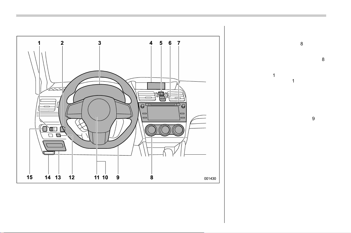
& Instrument panel
1) Illumination brightness control dial
(page 3-71)
2) Trunk opener switch (page 2-35)
3) Combination meter (page 3-8)
4) Multi-function display (color LCD)
(page 3-44)
5) Hazard warning flasher switch (page 3-8)
6) Multi-function display (color LCD) control
switches (page 3-44)
7) Audio (page 5-1)
8) Climate control (page 4-1)
9) Tilt/telescopic steering (page 3-85)
10) Horn (page 3-86)
11) SRS airbag (page 1-33)
12) Vehicle Dynamics Control OFF switch
(page 7-39)
13) Fuse box (page 11-42)
14) Hood lock release knob (page 11-9)
15) BSD/RCTA OFF switch (if equipped)
(page 7-57)
NOTE
For models with the EyeSight system:
Refer to the Owner’s Manual supple-
ment for the EyeSight system.
20
(23,1)
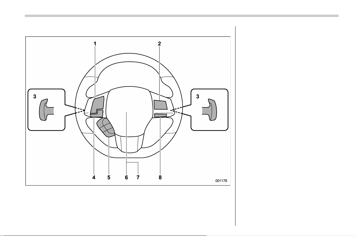
北米Model "A1700BE-B" EDITED: 2017/ 10/ 11
& Steering wheel
1) Audio control buttons (page 5-61)
2) Cruise control (page 7-53)
3) Shift paddle (CVT models) (page 7-25)
4) Hands-free switches (page 5-69)/Voice
command system (page 5-79)
5) Combination meter display (color LCD)
control switches (page 3-38)
6) SRS airbag (page 1-33)
7) Horn (page 3-86)
8) SI-DRIVE switches (except STI)
(page 7-28)
– CONTINUED –
21
0
(24,1)
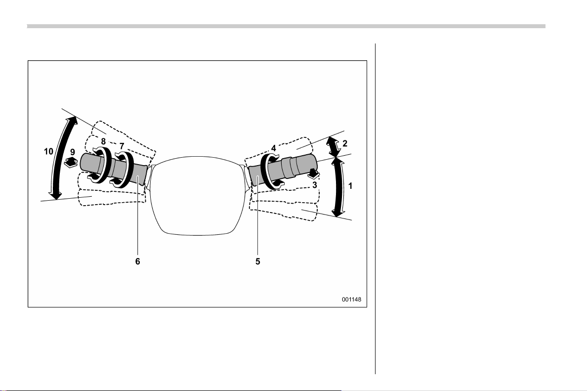
北米Model "A1700BE-B" EDITED: 2017/ 10/ 11
& Light control and wiper control levers/switches
1) Windshield wiper (page 3-72)
2) Mist (page 3-74)
3) Windshield washer (page 3-74)
4) Wiper intermittent time control switch
(page 3-74)
5) Wiper control lever (page 3-74)
6) Light control switch (page 3-63)
7) Fog light switch (page 3-72)
8) Headlight ON/OFF/AUTO (page 3-64)
9) Headlight flasher High/Low beam change
(page 3-65)
10) Turn signal lever (page 3-70)
22
(25,1)
北米Model "A1700BE-B" EDITED: 2017/ 10/ 11
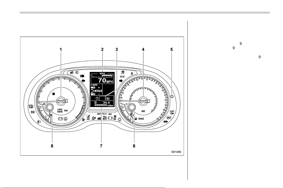
& Combination meter
! U.S.-spec. models
The illustration above is a typical example. For some models, the combination meter may
be slightly different than that shown in the illustration.
1) Tachometer (page 3-10)
2) Combination meter display (color LCD)
(page 3-38)
3) Select lever/gear position indicator
(page 3-34)
4) Speedometer (page 3-9)
5) Trip knob (page 3-9)
6) Fuel gauge (page 3-10)
7) Trip meter and odometer (page 3-9)
8) Temperature gauge (page 3-11)
– CONTINUED –
23
0
(26,1)
北米Model "A1700BE-B" EDITED: 2017/ 10/ 11
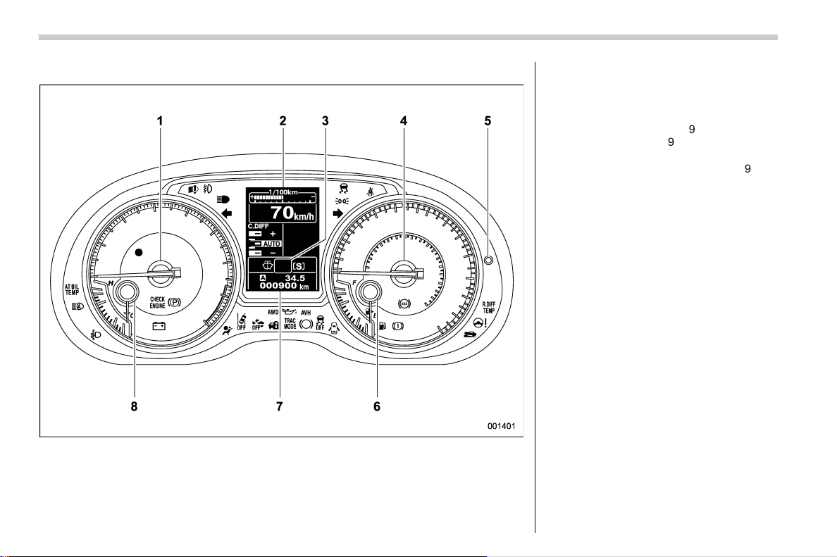
! Except U.S.-spec. models
The illustration above is a typical example. For some models, the combination meter may
be slightly different than that shown in the illustration.
1) Tachometer (page 3-10)
2) Combination meter display (color LCD)
(page 3-38)
3) Select lever/gear position indicator
(page 3-34)
4) Speedometer (page 3-9)
5) Trip knob (page 3-9)
6) Fuel gauge (page 3-10)
7) Trip meter and odometer (page 3-9)
8) Temperature gauge (page 3-11)
24
(27,1)
北米Model "A1700BE-B" EDITED: 2017/ 10/ 11
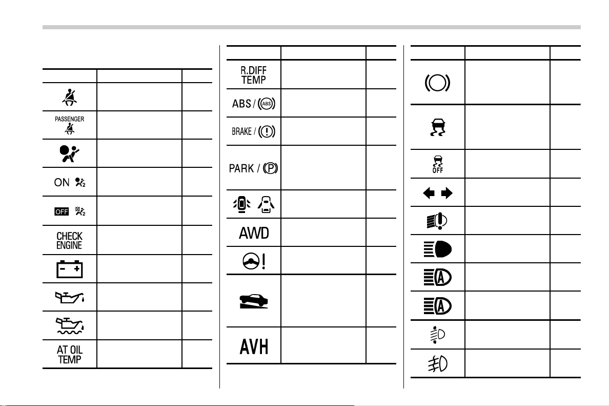
& Warning and indicator lights
Mark Name Page
Seatbelt warning light 3-14
Front passenger’s
seatbelt warning light
3-14
SRS airbag system
warning light
3-15
/
Front passenger’s
frontal airbag ON in-
dicator
3-16
/
Front passenger’s
frontal airbag OFF in-
dicator
3-16
CHECK ENGINE
warning light/Mal-
function indicator light
3-16
Charge warning light 3-17
Oil pressure warning
light
3-17
Engine oil level warn-
ing indicator (except
STI)
3-17
AT OIL TEMP warning
light (CVT models)
3-18
Mark Name Page
Rear differential oil
temperature warning
light (STI)
3-18
ABS warning light 3-20
Brake system warning
light
3-21
Electronic parking
brake indicator light
(models with electro-
nic parking brake
system)
3-23
/
Door open warning
light
3-25
AWD warning light
(if equipped)
3-25
Power steering warn-
ing light (except STI)
3-25
Hill start assist warn-
ing light/Hill start as-
sist OFF indicator light
(models without elec-
tronic parking brake
system)
3-24
Auto Vehicle Hold ON
indicator light (models
with electronic park-
ing brake system)
3-24
Mark Name Page
Auto Vehicle Hold op-
eration indicator light
(models with electro-
nic parking brake
system)
3-24
Vehicle Dynamics
Control warning light/
Vehicle Dynamics
Control operation in-
dicator light
3-26
Vehicle Dynamics
Control OFF indicator
light
3-27
Turn signal indicator
lights
3-35
LED headlight warn-
ing light (if equipped)
3-25
High beam indicator
light
3-35
High beam assist in-
dicator (green)
3-35
High beam assist
warning indicator
(yellow)
3-35
Automatic headlight
beam leveler warning
light (if equipped)
3-35
Front fog light indica-
tor light (if equipped)
3-35
– CONTINUED –
25
0
(28,1)
北米Model "A1700BE-B" EDITED: 2017/ 10/ 11
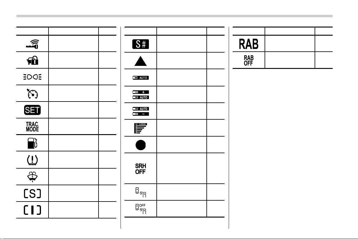
Mark Name Page
Access key warning
light (if equipped)
3-28
Security indicator light 3-33
Headlight indicator
light
3-35
Cruise control indica-
tor
3-35
Cruise control set in-
dicator
3-35
Traction mode indica-
tor
3-27
Low fuel warning light 3-24
Low tire pressure
warning light
(U.S.-spec. models)
3-19
Windshield washer
fluid warning indicator
3-18
Sport (S) mode indi-
cator (if equipped)
3-34
Intelligent (I) mode in-
dicator (if equipped)
3-34
Mark Name Page
Sport Sharp (S#)
mode indicator (if
equipped)
3-34
Shift-up indicator
(STI)
3-34
Driver’s control center
differential auto indi-
cator (STI)
3-36
Auto [+] mode indica-
tor (STI)
3-36
Auto [−] mode indica-
tor (STI)
3-36
Driver’s control center
differential indicator
and warning (STI)
3-36
REV indicator light
(STI)
3-37
Steering Responsive
Headlight warning in-
dicator/Steering Re-
sponsive Headlight
OFF indicator (if
equipped)
3-37
BSD/RCTA warning
indicator (if equipped)
3-37
BSD/RCTA OFF indi-
cator (if equipped)
3-37
Mark Name Page
RAB warning indica-
tor (if equipped)
3-37
RAB OFF indicator (if
equipped)
3-37
26

(29,1)
北米Model "A1700BE-B" EDITED: 2017/ 10/ 11
Function settings
A SUBARU dealer can change the settings of the functions shown in the following table to meet your personal requirements. Contact
your nearest SUBARU dealer for details. In addition, you can change the settings for some of these functions using the multi-function
display (color LCD). For more information, refer to “Multi-function display (color LCD)” F3-44.
Item Function Possible settings Default setting Page
Alarm system Alarm system Operation/Non-operation Operation 2-24
Monitoring start delay time (after closure of doors) 0 seconds/30 seconds 30 seconds 2-25
Impact sensor operation (only models with shock
sensors (dealer option))
Operation/Non-operation Non-operation 2-30
Passive arming (models without “keyless access
with push-button start system”)
Operation/Non-operation Non-operation 2-29
Dome light and map lights (models with moonroof)
illumination
ON/OFF OFF 2-24
Keyless access (if equipped) Hazard warning flasher Operation/Non-operation Operation 2-11
Audible signal Operation/Non-operation Operation 2-14
Audible signal volume Level 1 - 7 Level 5 2-14
Door unlock selection function (driver’s door
unlock)
Driver’s door only/All
doors
Driver’s door
only
2-12
Remote keyless entry system Hazard warning flasher Operation/Non-operation Operation 2-18
Audible signal Operation/Non-operation Operation 2-20
Audible signal volume Level 1 - 7 Level 5 2-20
Remote trunk open function Activation of trunk opening by remote transmitter/
access key fob
Operation/Non-operation Operation 2-20
Key lock-in prevention Key lock-in prevention Operation/Non-operation Operation 2-7
Defogger and deicer system for
models with the automatic climate
control system
Rear window defogger, outside mirror defogger
and windshield wiper deicer
Operation for 15 minutes/
Continuous operation
Operation for
15 minutes
3-84
– CONTINUED –
27
0

(30,1)
北米Model "A1700BE-B" EDITED: 2017/ 10/ 11
Item Function Possible settings Default setting Page
Dome light Operation of dome light/map light OFF delay timer OFF/10 seconds/20 sec-
onds/30 seconds
30 seconds 6-3
Map light (models with moonroof)
Battery drainage prevention function Battery drainage prevention function Operation/Non-operation Operation 2-6
Seatbelt warning Sounds a chime while driving Operation/Non-operation Operation 3-14
Auto on/off headlights (if equipped) Sensitivity of the operation of the auto on/off
headlights
Low/Normal/High/Very
high
Normal 3-64
Windshield wiper Auto-on/off wiper linked headlights Operation/Non-operation Operation 3-64
Auto dimmer cancel Sensitivity of the operation of the auto dimmer
cancel
OFF/Min/Low/Mid/Hi/Max Mid 3-71
Welcome lighting Approaching (operation of timer) OFF/30 seconds/60 sec-
onds/90 seconds
30 seconds 3-64
Exiting (operation of timer)
High beam assist function (models
with the EyeSight system)
High beam assist function Operation/Non-operation Operation 3-65
One-touch lane changer Operation of the one-touch lane changer Operation/Non-operation Operation 3-70
28

(33,1)
北米Model "A1700BE-B" EDITED: 2017/ 10/ 11
Front seats .............................................................. 1-2
Manual seat ........................................................... 1-4
Power seat (driver’s seat – if equipped).. ................ 1-5
Head restraint adjustment ...................................... 1-5
Seat heater (if equipped) ........................................1-7
Rear seats................................................................1-8
Head restraint adjustment ...................................... 1-8
Folding down the rear seatback ............................1-10
Armrest (except TYPE RA) ....................................1-12
Seatbelts................................................................ 1-12
Seatbelt safety tips ...............................................1-12
Emergency Locking Retractor (ELR)......................1-13
Automatic Locking Retractor/Emergency Locking
Retractor (ALR/ELR)............................................1-13
Seatbelt warning light and chime ..........................1-14
Fastening the seatbelt...........................................1-14
Seatbelt maintenance............................................ 1-17
Front seatbelt pretensioners................................ 1-17
Driver’s seatbelt....................................................1-18
Front passenger’s seatbelt....................................1-18
Components that will operate with the seatbelt
pretensioner(s) simultaneously ...........................1-19
Safety tips ............................................................1-20
System monitors................................................... 1-20
System servicing ..................................................1-20
Precautions against vehicle modification...............1-21
Child restraint systems ........................................ 1-21
Safety tips for installing child restraint systems.... 1-22
Where to place a child restraint system ................1-23
Choosing a child restraint system.........................1-25
Installing child restraint systems with ALR/ELR
seatbelt .............................................................1-25
Installing a booster seat ....................................... 1-29
Installation of child restraint systems by use of
lower and tether anchorages (LATCH) ................ 1-30
Top tether anchorages ..........................................1-32
*SRS airbag
(Supplemental Restraint System airbag) ......... 1-33
General precautions regarding SRS airbag
system .............................................................. 1-34
General precautions regarding SRS airbag
system for accessories and any objects.............1-36
General precautions regarding SRS airbag
system for children............................................ 1-38
Components......................................................... 1-41
SUBARU advanced frontal airbag system..............1-43
SRS side airbag and SRS curtain airbag ............... 1-53
SRS airbag system monitors.................................1-62
SRS airbag system servicing ................................ 1-63
Precautions against vehicle modification .............. 1-64
How to contact the vehicle manufacturer
concerning modifications for persons with
disabilities that may affect the advanced airbag
system .............................................................. 1-65
Seat, seatbelt and SRS airbags
1
(34,1)
北米Model "A1700BE-B" EDITED: 2017/ 10/ 11
Front seats
WARNING
. Never adjust the seat while driv-
ing to avoid loss of vehicle con-
trol and personal injury.
. Before adjusting the seat, make
sure the hands and feet of rear
seat passengers and cargo are
clear of the adjusting mechan-
ism.
. After adjusting the seat, push it
slightly to make sure it is se-
curely locked. If the seat is not
securely locked, it may move or
the seatbelt may not operate
properly.
. Do not put objects under the front
seats. They may interfere with
front seat locking and cause an
accident.
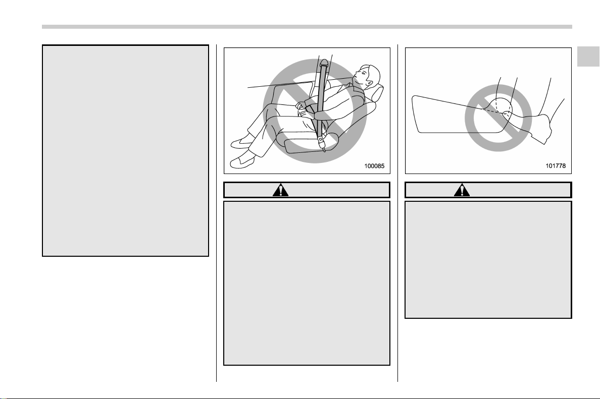
. Seatbelts provide maximum re-
straint when the occupant sits
well back and upright in the seat.
To reduce the risk of sliding
under the seatbelt in a collision,
the front seatbacks should be
always used in the upright posi-
tion while the vehicle is running.
If the front seatbacks are not
used in the upright position in a
collision, the risk of sliding under
the lap belt and of the lap belt
sliding up over the abdomen will
increase, and both can result in
serious internal injury or death.
. The SRS airbags deploy with
considerable speed and force.
Occupants who are out of proper
position when the SRS airbag
deploys could suffer very serious
injuries. Because the SRS airbag
needs enough space for deploy-
ment, the driver should always sit
upright and well back in the seat
as far from the steering wheel as
practical while still maintaining
full vehicle control and the front
passenger should move the seat
as far back as possible and sit
upright and well back in the seat.
WARNING
Place children in the rear seat prop-
erly restrained at all times. The SRS
airbag deploys with considerable
speed and force and can injure or
even kill children, especially if they
are not restrained or improperly
restrained. Because children are
lighter and weaker than adults, their
risk of being injured from deploy-
ment is greater. For that reason, we
strongly recommend that ALL chil-
dren (including those in child seats
and those that have outgrown child
restraint devices) sit in the REAR
seat properly restrained at all times
in a child restraint device or in a
seatbelt, whichever is appropriate
Seat, seatbelt and SRS airbags/Front seats
1-2
(35,1)
北米Model "A1700BE-B" EDITED: 2017/ 10/ 11
for the child’s age, h eight and
weight. Secure ALL types of child
restraint devices (including forward
facing child seat) in the REAR seats
at all times.
NEVER INSTALL A FORWARD OR
REARWARD FACING CHILD SEAT IN
THE FRONT SEAT. DOING SO RISKS
SERIOUS INJURY OR DEATH TO
THE CHILD BY PLACING THE
CHILD’S HEAD TOO CLOSE TO
THE SRS AIRBAG.
According to accident statistics,
children are safer when properly
restrained in the rear seating posi-
tions than in the front seating posi-
tions. For instructions and precau-
tions concerning child restraint sys-
tems, refer to “Child restraint sys-
tems” F1-21.
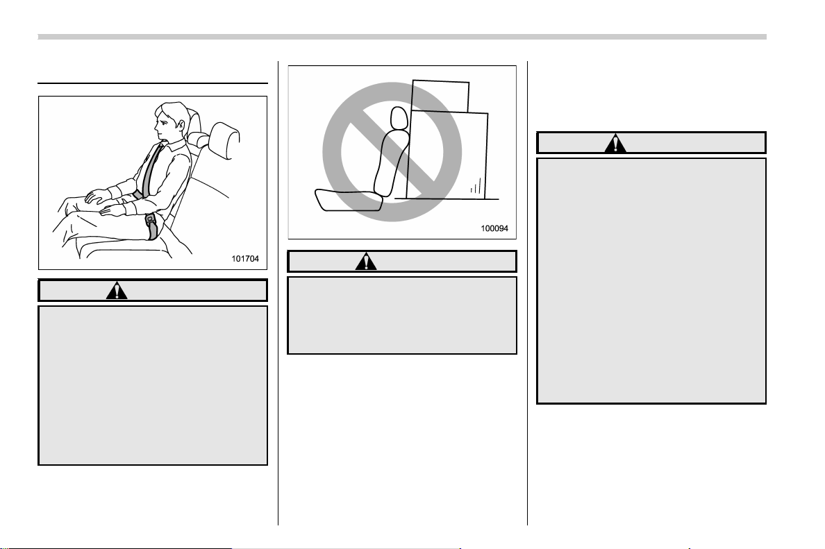
WARNING
To prevent the passenger from slid-
ing under the seatbelt in the event of
a collision, observe the following
precautions:
. Keep the seatback in the upright
position while the vehicle is in
motion.
. Do not place objects such as
cushions between the passenger
and the seatback.
Otherwise, the risk of sliding under
the lap belt and of the lap belt sliding
up over the abdomen will increase,
and both can result in serious inter-
nal injury or death.
WARNING
Do not let rear passengers rest their
feet between the front seatback and
seat cushion. Doing so may lead to
improper operation of the following
systems and could result in serious
injury.
. Occupant detection system
. SRS side airbag
. Seat heater (if equipped)
. Power seat (if equipped)
– CONTINUED –
Seat, seatbelt and SRS airbags/Front seats
1-3
1
(36,1)
北米Model "A1700BE-B" EDITED: 2017/ 10/ 11
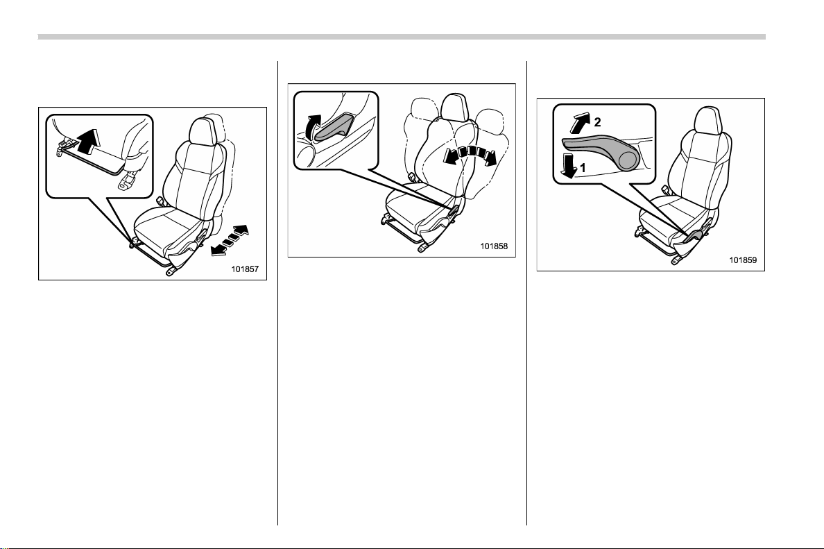
& Manual seat
! Forward and backward adjustment
1. Sit in the seat to adjust.
2. Pull the lever upward, slide the seat to
the desired position, and then release the
lever.
3. Try to move the seat back and forth to
make sure that it is securely locked into
place.
! Reclining the seatback
1. Pull up the reclining lever, adjust the
seatback to the desired position, and then
release the lever.
2. Make sure the seatback is securely
locked into place.
The seatback placed in a reclined position
can spring back upward with force when
pulling the lever. While operating the lever
to return the seatback, hold the seatback
lightly so that it may b e raised back
gradually.
! Seat cushion height adjustment
(driver’s seat)
1) When the lever is pushed down, the seat
is lowered.
2) When the lever is pulled up, the seat
rises.
Move the seat cushion adjustment lever up
or down to adjust the seat cushion height.
Seat, seatbelt and SRS airbags/Front seats
1-4
(37,1)
北米Model "A1700BE-B" EDITED: 2017/ 10/ 11
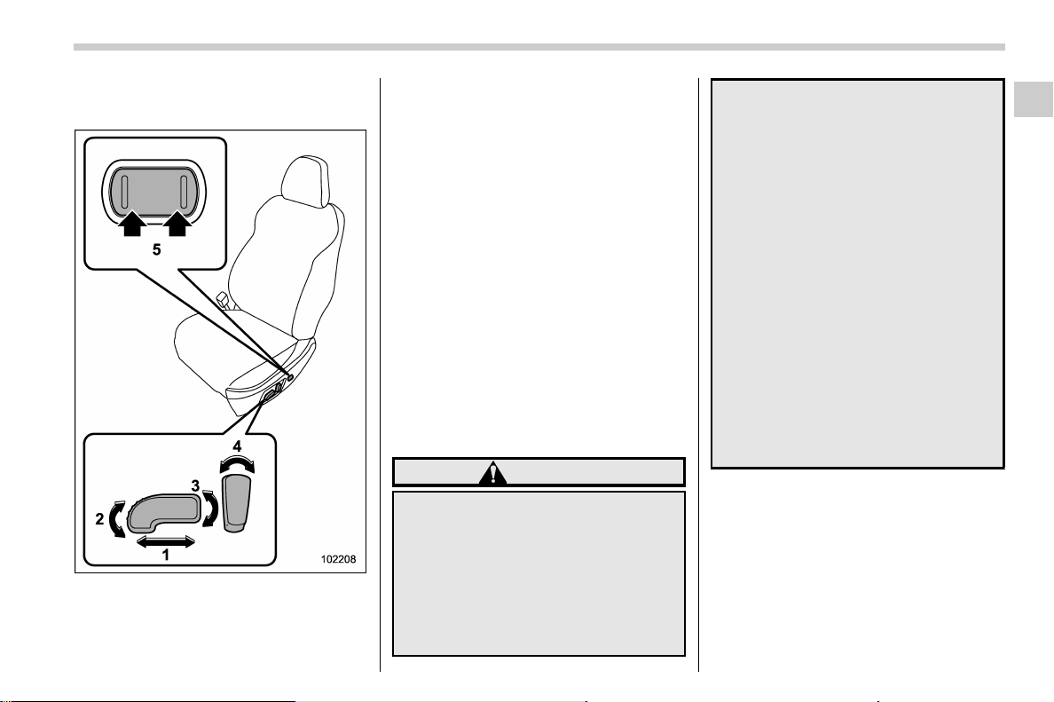
& Power seat (driver’s seat – if
equipped)
1) Seat position forward/backward con-
trol switch
To adjust the seat forward or backward,
move the control switch forward or
backward. During forward/backward ad-
justment of the seat, you cannot adjust
the seat cushion angle or seat cushion
height.
2) Seat cushion angle control switch
To adjust the seat cushion angle, pull up
or push down the front end of the control
switch.
3) Seat height control switch
To adjust the seat height, pull up or push
down the rear end of the control switch.
4) Seatback angle (reclining) control
switch
To adjust the angle of the seatback, move
the control switch.
5) Lumbar support control switch (dri-
ver’s seat only)
To increase lower back support, push the
front side of the switch. To decrease
lower back support, push the rear side of
the switch.
& Head restraint adjustment
WARNING
. Never drive the vehicle with the
head restraints removed because
they are designed to reduce the
risk of serious neck injury in the
event that the vehicle is struck
from the rear. Also, never install
the head restraints the opposite
way round. Doing so will prevent
the head restraints from function-
ing as intended. Therefore, when
you remove the head restraints,
you must reinstall all head re-
straints correctly to protect vehi-
cle occupants.
. All occupants, including the dri-
ver, should not operate a vehicle
or sit in a vehicle’s seat until the
head restraints are placed in their
proper positions in order to mini-
mize the risk of neck injury in the
event of a crash.
. The front seat head restraints are
designed to be installed into the
front seats only. The rear seat
head restraints are designed to
be installed into the rear seats
only. Do not attempt to install the
front seat head restraints into the
rear seats, or the rear seat head
restraints into the front seats.
NOTE
It is possible to adjust the angle of the
front seat head restraints only. When
installing the front seat head restraints,
make sure that the angle of the head
restraints can be adjusted.
Both the driver’s seat and front passen-
ger’s seat are equipped with head re-
straints. Both head restraints are adjusta-
– CONTINUED –
Seat, seatbelt and SRS airbags/Front seats
1-5
1

(38,1)
北米Model "A1700BE-B" EDITED: 2017/ 10/ 11
ble in the following ways.
! Head restraint height adjustment
1) Head restraint
2) Release button
To raise:
Pull the head restraint up.
To lower:
Push the head restraint down while press-
ing the release button on the top of the
seatback.
To remove:
While pressing the release button, pull out
the head restraint.
To install:
Install the head restraint into the holes that
are located on the top of the seatback until
the head restraint locks. Press and hold
the release button to lower the head
restraint.
Adjust each head restraint so that the
center of the head restraint is closest to the
top of the occupant’s ears.
NOTE
When the head restraint will not move
in or out due to insufficient clearance
between the head restraint and the roof,
tilt the seat and then perform the
installation and removal tasks.
! Head restraint angle adjustment
It is possible to adjust the angle of the head
restraint in several steps. While maintain-
ing a suitable driving posture, adjust the
head restraint to a position where the back
of your head is as close to the head
restraint as possible.
To tilt:
Tilt the head restraint by hand to the
preferred position. A click will be audible
when the head restraint is locked.
To return:
Tilt the head restraint once as far forward
as it can go. The head restraint will
automatically return to the fully upright
position. Then, adjust the head restraint
again to the preferred angle.
Seat, seatbelt and SRS airbags/Front seats
1-6
(39,1)
北米Model "A1700BE-B" EDITED: 2017/ 10/ 11
Seat heater (if equipped)
The front seats are equipped with a seat
heater.
The seat heater operates when the ignition
switch is either in the “ACC” or “ON”
position.
CAUTION
. People with delicate skin may
suffer slight burns even at low
temperatures if they use the seat
heater for a long period of time.
When using the heater, always be
sure to warn the persons con-
cerned.
. Do not put anything on the seat
which insulates against heat,
such as a blanket, cushion, or
similar items. This may cause the
seat heater to overheat.
. When the seat is warmed enough
or before you leave the vehicle,
be sure to turn off the seat heater.
NOTE
Use of the seat heater for a long period
of time while the engine is not running
can cause battery discharge.
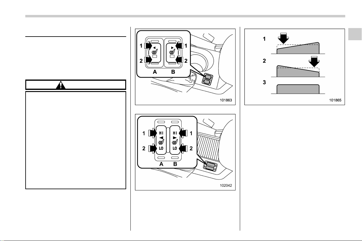
Type A
Type B
1) HIGH (HI) – Rapid heating
2) LOW (LO) – Normal heating
3) Off
A) Left-hand side
B) Right-hand side
To turn on the seat heater, push the “LOW”
(“LO”)or“HIGH” (“HI”) position on the
switch, as desired, depending on the
temperature.
Selecting the “HIGH” (“HI”) position will
cause the seat to heat up quicker.
To turn off the seat heater, lightly press the
opposite side of the current position.
The indicator located on the switch illumi-
nates when the seat heater is in operation.
When the seat is warmed enough or
before you leave the vehicle, be sure to
turn the switch off.
Seat, seatbelt and SRS airbags/Seat heater
1-7
1
(40,1)
北米Model "A1700BE-B" EDITED: 2017/ 10/ 11
Rear seats
WARNING
Seatbelts provide maximum re-
straint when the occupant sits well
back and upright in the seat. Do not
put cushions or any other materials
between occupants and seatbacks
or seat cushions. If you do so, the
risk of sliding under the lap belt and
of the lap belt sliding up over the
abdomen will increase, and both can
result in serious internal injury or
death.
WARNING
Never stack luggage or other cargo
higher than the top of the seatback
because it could tumble forward and
injure passengers in the event of a
sudden stop or accident.
& Head restraint adjustment
Both the rear window side seats and the
rear center seat are equipped with head
restraints.
WARNING
. Never drive the vehicle with the
head restraints removed because
they are designed to reduce the
risk of serious neck injury in the
event that the vehicle is struck
from the rear. Therefore, when
you have removed the head re-
straints, you must reinstall all
head restraints to protect vehicle
occupants.
. All occupants, including the dri-
ver, should not operate a vehicle
or sit in a vehicle’s seat until the
head restraints are placed in their
proper positions in order to mini-
mize the risk of neck injury in the
event of a crash.
Seat, seatbelt and SRS airbags/Rear seats
1-8
(41,1)
北米Model "A1700BE-B" EDITED: 2017/ 10/ 11
! Rear windows side seating position
1) Head restraint
2) Release button
To remove:
While pressing the release button, pull out
the head restraint.
To install:
Install the head restraint into the holes that
are located on the top of the seatback until
the head restraint locks. Press and hold
the release butt on to lower the head
restraint.
After installing the head restraint, make
sure it is securely locked.
NOTE
When the head restraint cannot be
pulled out or installed due to insuffi-
cient clearance between the head re-
straint and the roof, tilt the seat and
then perform the installation and re-
moval tasks.
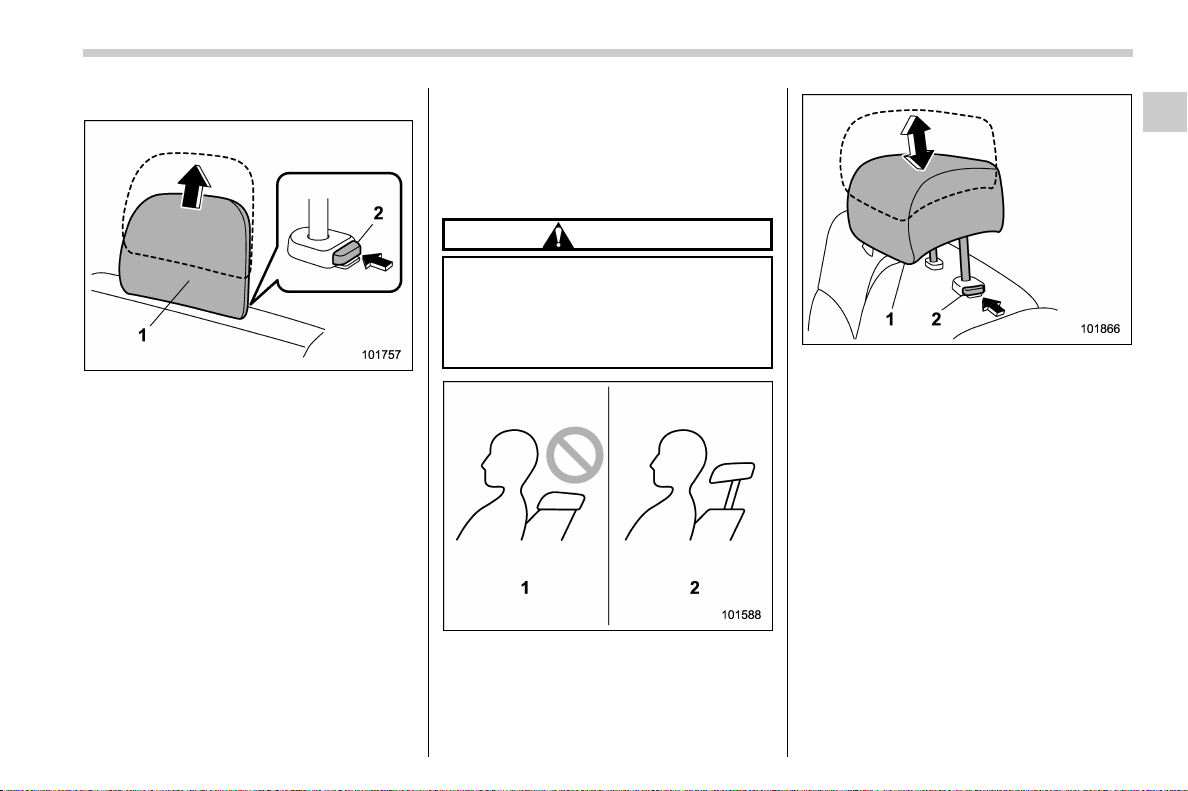
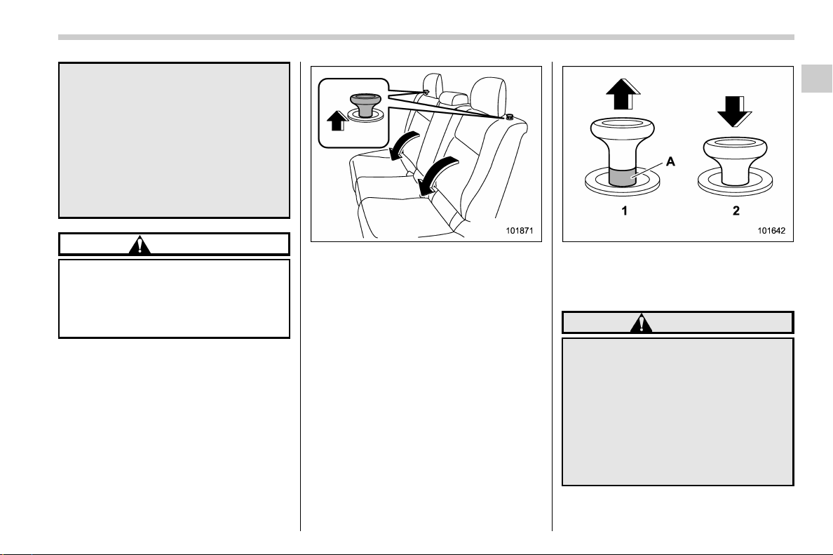
! Rear center seating position
CAUTION
The head restraint is not intended to
be used in the retracted position.
Before sitting on the seat, raise the
head restraint to the extended posi-
tion.
1) Incorrect (retracted position)
2) Correct (extended position)
1) Head restraint
2) Release button
To raise:
Pull the head restraint up.
To lower:
Push the head restraint down while press-
ing the release button on the top of the
seatback.
To remove:
While pressing the release button, pull out
the head restraint.
To install:
Install the head restraint into the holes that
are located on the top of the seatback until
the head restraint locks. Press and hold
the release button to lower the head
restraint.
– CONTINUED –
Seat, seatbelt and SRS airbags/Rear seats
1-9
1
(42,1)
北米Model "A1700BE-B" EDITED: 2017/ 10/ 11
When the rear-center seating position is
occupied, raise the head restraint to the
extended position. When the rear center
seating position is not occupied, lower the
head restraint to improve rearward visibi-
lity.
& Folding down the rear seat-
back
WARNING
. When you fold down the seat-
back, check that there are no
passengers or objects on the rear
seat. Not doing so creates a risk
of injury or property damage if
the seat back suddenly folds
down.
. Never allow passengers to ride
on the folded rear seatback or in
the trunk. Doing so may result in
serious injury or death.
. Secure all objects and especially
long items properly to prevent
them from being thrown around
inside the vehicle and causing
serious injury during a sudden
stop, a sudden steering maneu-
ver or a rapid acceleration.
. When you return the seatback to
its original position, shake the
seatback slightly to confirm that
it is securely fixed in place. If the
seatback is not securely fixed in
place, the seatback may sud -
denly fold down in the event of
sudden braking, or objects may
move out from the trunk, which
could cause s erious injury or
death.
Lock release knob
1) Unlocked
2) Locked
A) Unlocking marker in red
1) Securing hook
WARNING
When the seatback is returned to its
original position, observe the fol-
Seat, seatbelt and SRS airbags/Rear seats
1-10
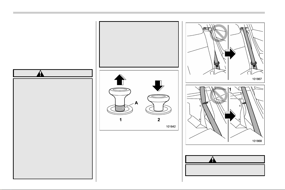
(43,1)
北米Model "A1700BE-B" EDITED: 2017/ 10/ 11
lowing precautions. Failure to do so
may lead to serious injury or an
accident because the operation effi-
ciency of the seatbelt is inhibited.
. The seatbelt should not be
caught in the seatback and it
should be fully visible.
. The seatbelt should not pass
behind the securing hook for the
seatback.
CAUTION
Do not hang luggage etc. on the
securing hook. The possibility ex-
ists that the seatback may not be
able to be fixed firmly in place. This
could lead to unexpected accidents.
1. Lower the head restraint of the rear
center seating position.
Release knob
2. Unlock the seatback by pulling the lock
release knob then fold the seatback down.
To return the seatback to its original
position, raise the seatback until it locks
into place and make sure that the unlock-
ing marker on the lock release knob is no
longer visible.
Lock release knob
1) Unlocked
2) Locked
A) Unlocking marker in red
WARNING
After returning the seatback to its
original position, confirm that the
unlocking marker of the lock release
knob is no longer visible. Failure to
do so could lead to serious injury or
death in the event of an accident.
When you return the seatback to its
original position, shake the seat-
back to confirm that it is securely
fixed in place.
– CONTINUED –
Seat, seatbelt and SRS airbags/Rear seats
1-11
1
(44,1)
北米Model "A1700BE-B" EDITED: 2017/ 10/ 11
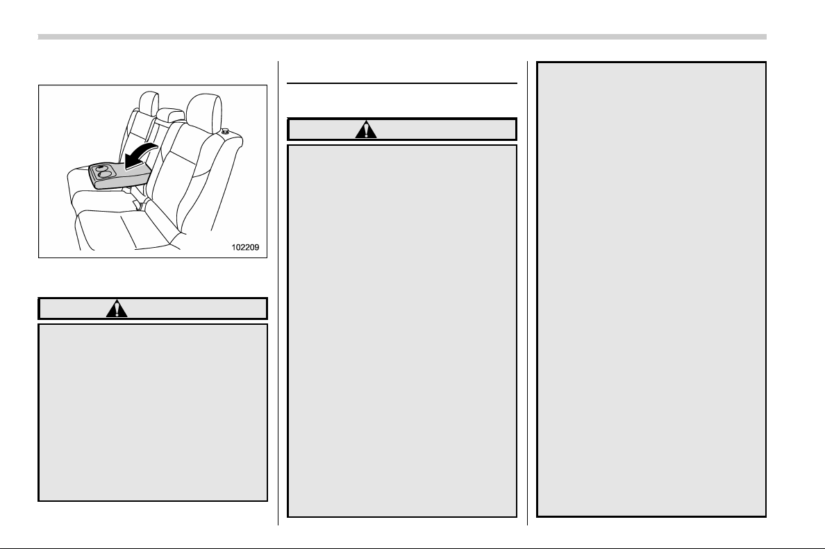
& Armrest (except TYPE RA)
To lower the armrest, pull the armrest ’s top
edge.
WARNING
. Make sure to have the rear pas-
sengers wear the seatbelts be-
fore lowering the armrest. If the
rear passengers wear the seat-
belts after lowering the armrest,
seatbelts cannot provide maxi-
mum restraint, causing serious
injuries.
. To avoid serious injury, never
allow passengers to sit on the
center armrest while the vehicle
is in motion.
Seatbelts
& Seatbelt safety tips
WARNING
. All persons in the vehicle should
fasten their seatbelts BEFORE
the vehicle starts to move. Other-
wise, the possibility of serious
injury becomes greater in the
event of a sudden stop or acci-
dent.
. All belts should fit snugly in order
to provide full restraint. Loose
fitting belts are not as effective in
preventing or reducing injury.
. Each seatbelt is designed to sup-
port only one person. Never use a
single belt for two or more per-
sons – even children. Otherwise,
in an accident, serious injury or
death could result.
. Replace all seatbelt assemblies
including retractors and attach-
ing hardware worn by occupants
of a vehicle that has been in a
serious accident. Also, be sure to
replace seatbelt assemblies that
show signs of severe fraying or
having been cut. The entire as-
sembly should be replaced even
if damage is not obvious.
. Place children in the rear seat
properly restrained at all times.
The SRS airbag deploys with
considerable speed and force
and can injure or even kill chil-
dren, especially if they are not
restrained or improperly re-
strained. Bec ause children are
lighter and weaker than adults,
their risk of being injured from
deployment is greater. For that
reason, we strongly recommend
thatALLchildren(including
those in child seats and those
that have outgrown child re-
straint devices) sit in the REAR
seat properly restrained at all
times in a child restraint device
or in a seatbelt, whichever is
appropriate for the child’s height
and weight.
Secure ALL types of child re-
straint devices (including for-
ward facing child seats) in the
REAR seats at all times.
NEVER INSTALL A FORWARD
OR REARWARD FACING CHILD
SEAT IN THE FRONT SEAT.
DOING SO RISKS SERIOUS IN-
JURY OR DEATH TO THE CHILD
BY PLACING THE CHILD’S HEAD
Seat, seatbelt and SRS airbags/Seatbelts
1-12
(45,1)
北米Model "A1700BE-B" EDITED: 2017/ 10/ 11
TOO CLOSE TO THE SRS AIR-
BAG.
According to accident statistics,
children are safer when properly
restrained in the rear seating
positions than in the front seating
positions. For instructions and
precautions concerning the child
restraint system, refer to “Child
restraint systems” F1-21.
Your vehicle is equipped with a crash
sensing and diagnostic module, which will
record the use of the seatbelt by the front
passenger when any of the SRS frontal,
side and curtain airbags deploy.
! Infants or small children
Use a child restraint system that is suitable
for your vehicle. Refer to “Child restraint
systems” F1-21.
! Children
If a child is too big for a child restraint
system, the child should sit in the rear seat
and be restrained using the seatbelts.
According to accident statistics, children
are safer when properly restrained in the
rear seating positions than in the front
seating positions. Never allow a child to
stand up or kneel on the seat.
If the shoulder portion of the belt crosses
the face or neck, move the child closer to
the belt buckle to help provide a good
shoulder belt fit. Take care to securely
place the lap belt as low as possible on the
hips and not on the child’s waist. If the
shoulder portion of the belt cannot be
properly positioned, use a child restraint
system. Never place the shoulder belt
under the child’s arm or behind the child’s
back.
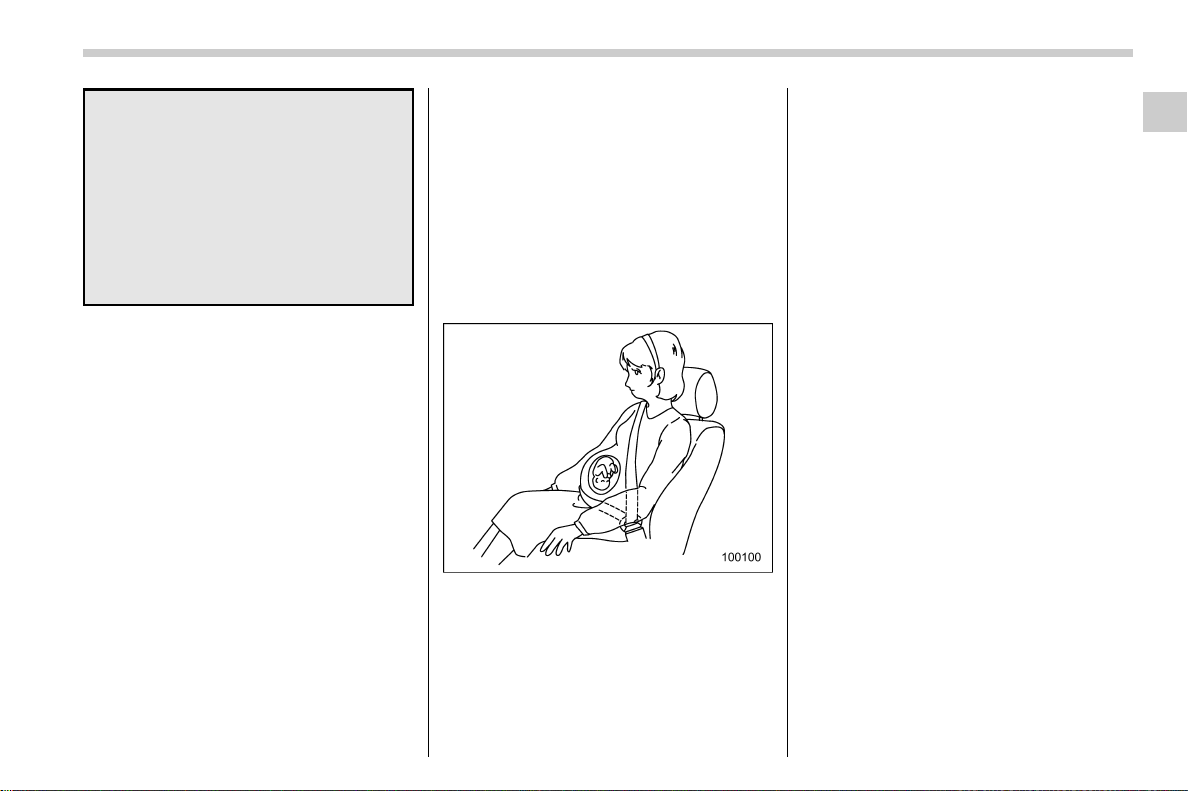
! Expectant mothers
Expectant mothers also need to use the
seatbelts. They should consult their doctor
for specific recommendations. The lap belt
should be worn securely and as low as
possible over the hips, not over the waist.
& Emergency Locking Retrac-
tor (ELR)
The driver’s seatbelt has an Emergency
Locking Retractor (ELR).
The emergency locking retractor allows
normal body movement but the retractor
locks automatically during a sudden stop,
impact or if you pull the belt very quickly
out of the retractor.
& Automatic Locking Retractor/
Emergency Locking Retrac-
tor (ALR/ELR)
Each passenger’s seatbelt has an Auto-
matic Locking Retractor/Emergency Lock-
ing Retractor (ALR/ELR). The Automatic
Locking Retractor/Emergency Locking
Retractor normally functions as an Emer-
gency Locking Retractor (ELR). The ALR/
ELR has an additional locking mode
“Automatic Locking Retractor ( ALR)
mode” intended to secure a child restraint
system.
The ALR mode functions as follows.
When the seatbelt is once drawn out
completely and is then retracted even
slightly, the retractor locks the seatbelt in
that position and the seatbelt cannot be
extended. As the belt is rewinding, clicks
will be heard which indicate the retractor
functions as an ALR. When the seatbelt is
– CONTINUED –
Seat, seatbelt and SRS airbags/Seatbelts
1-13
1
(46,1)
北米Model "A1700BE-B" EDITED: 2017/ 10/ 11
retracted fully, the ALR mode is released.
When securing a child restraint system on
the rear seats by the use of the seatbelt,
change the seatbelt over to the Automatic
Locking Retractor (ALR) mode.
After removing the child restraint system,
make sure that the seatbelt retracts fully
and the retractor returned to the Emer-
gency Locking Retractor (ELR) mode.
For instructions on how to convert the
retractor to the ALR mode and restore it to
the ELR mode, refer to “Installing child
restraint systems with ALR/ELR seatbelt”
F1-25.
& Seatbelt warning light
and chime
Refer to “Seatbelt warning light and chime”
F3-14.
& Fastening the seatbelt
WARNING
. Never use a belt that is twisted or
reversed. In an accident, this can
increase the risk or severity of
injury.
. Keep the lap belt as low as
possible on your hips. In a colli-
sion, this spreads the force of the
lap belt over stronger hip bones
instead of across the weaker
abdomen.
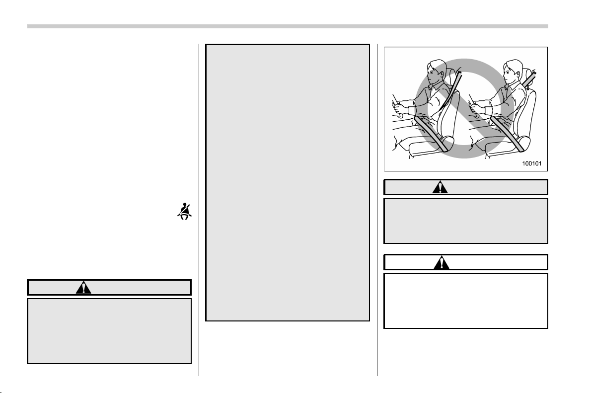
. Seatbelts provide maximum re-
straint when the occupant sits
well back and upright in the seat.
To reduce the risk of sliding
under the seatbelt in a collision,
the front seatbacks should be
always used in the upright posi-
tion while the vehicle is running.
If the front seatbacks are not
used in the upright position in a
collision, the risk of sliding under
the lap belt and of the lap belt
sliding up over the abdomen will
increase, and both can result in
serious internal injury or death.
. Do not put cushions or any other
materials between occupants
and seatbacks or seat cushions.
If you do so, the risk of sliding
under the lap belt and of the lap
belt sliding up over the abdomen
will increase, and both can result
in serious internal injury or death.
WARNING
Never place the shoulder belt under
the arm or behind the back. If an
accident occurs, this can increase
the risk or severity of injury.
CAUTION
Metallic parts of the seatbelt can
become very hot in a vehicle that has
been closed up in sunny weather;
they could burn an occupant. Do not
touch such hot parts until they cool.
Seat, seatbelt and SRS airbags/Seatbelts
1-14
(47,1)
北米Model "A1700BE-B" EDITED: 2017/ 10/ 11
! Front seatbelts
1. Adjust the seat position according to
the following procedure.
Driver’s seat: Adjust the seatback to the
upright position. Move the seat as far from
the steering wheel as practical while still
maintaining full vehicle control.
Front passenger’s seat: Adjust the seat-
back to the upright position. Move the seat
as far back as possible.
2. Sit well back in the seat.
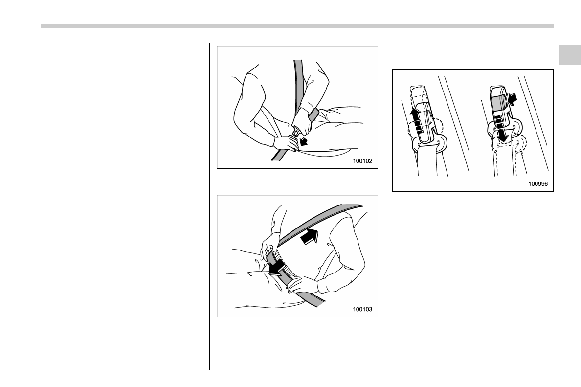
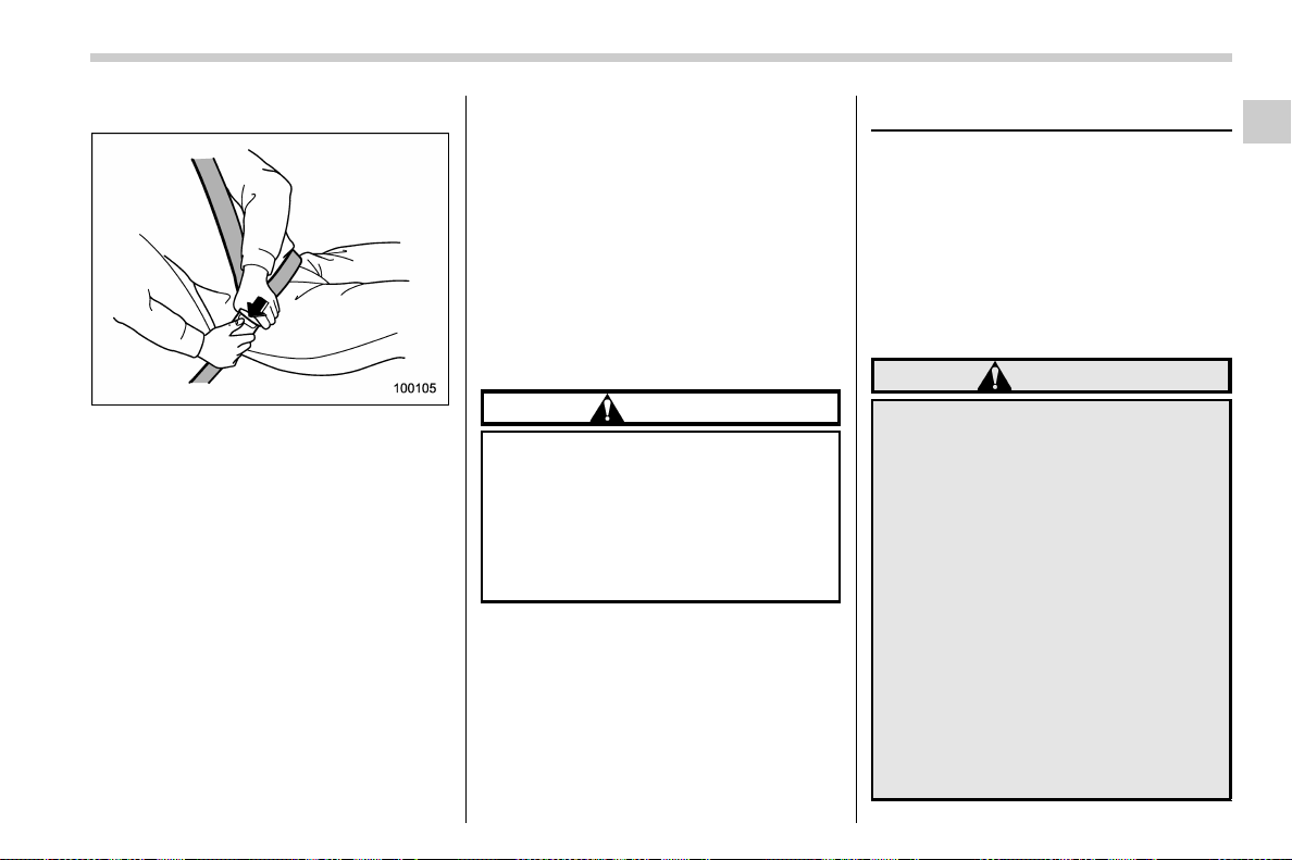
3. Pick up the tongue plate and pull the
belt out slowly. Do not let it get twisted.
. If the belt stops before reaching the
buckle, return the belt slightly and pull it
out more slowly.
. If the belt still cannot be unlocked, let
the belt retract slightly after pulling it
strongly, then pull it out slowly again.
4. Insert the tongue plate into the buckle
until you hear a click.
5. To make the lap part tight, pull up on
the shoulder belt.
6. Place the lap belt as low as possible on
your hips, not on your waist.
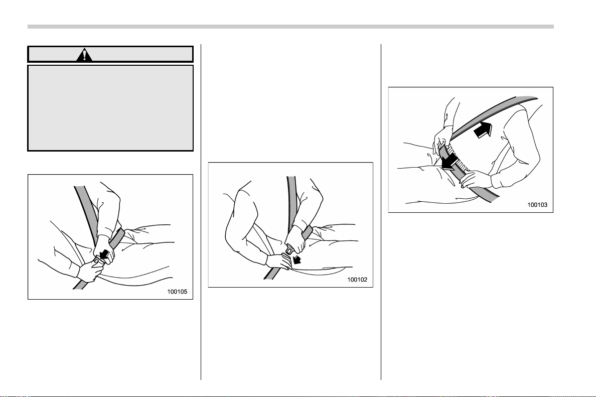
! Adjusting the front seat shoulder
belt anchor height
Adjust the shoulder belt anchor height to
the position best suited for the driver/front
passenger. Always adjust the anchor
height so that the shoulder belt passes
over the middle of the shoulder without
touching the neck.
To raise:
Slide the anchor up.
To lower:
Pull the release knob and slide the anchor
down.
Pull down on the anchor to make sure that
it is locked in place.
– CONTINUED –
Seat, seatbelt and SRS airbags/Seatbelts
1-15
1
(48,1)
北米Model "A1700BE-B" EDITED: 2017/ 10/ 11
WARNING
When wearing the seatbelts, make
sure the shoulder portion of the
webbing does not pass over your
neck. If it does, adjust the seatbelt
anchor to a lower position. Placing
the shoulder belt over the neck may
result in neck injury during sudden
braking or in a collision.
! Unfastening the seatbelt
1. Push the button on the buckle.
2. Allow the seatbelt to retract slowly to
avoid the seatbelt being tangled or twisted.
Before closing the door, make sure that the
belts are retracted properly to avoid
catching the belt webbing in the door.
! Rear seatbelts
1. Sit well back in the seat.
2. Pick up the tongue plate and pull the
belt out slowly. Do not let it get twisted.
. If the belt stops before reaching the
buckle, return the belt slightly and pull it
out more slowly.
. If the belt still cannot be unlocked, let
the belt retract slightly after pulling it
strongly, then pull it out slowly again.
3. Insert the tongue plate into the buckle
until you hear a click.
NOTE
The center seatbelt buckle is marked as
“CENTER”.
4. To make the lap part tight, pull up on
the shoulder belt.
5. Place the lap belt as low as possible on
your hips, not on your waist.
Seat, seatbelt and SRS airbags/Seatbelts
1-16
(49,1)
北米Model "A1700BE-B" EDITED: 2017/ 10/ 11
! Unfastening the seatbelt
1. Push the button on the buckle.
2. Allow the seatbelt to retract slowly to
avoid the seatbelt being tangled or twisted.
Before closing the door, make sure that the
belts are retracted properly to avoid
catching the belt webbing in the door.
& Seatbelt maintenance
To clean the seatbelts, use lukewarm
water with mild soap. Do not use the
seatbelts until they are dry. Never bleach
or dye the bel ts bec ause this co uld
seriously affect their strength.
Inspect the seatbelts and attachments
including the webbing and all hardware
periodically for cracks, cuts, gashes, tears,
damage, loose bolts or worn areas. Re-
place the seatbelts even if only minor
damage is found.
CAUTION
. Keep the belts free of polishes,
oils, chemicals and particularly
battery acid.
. Never attempt to make modifica-
tions or changes that will prevent
the seatbelt from operating prop-
erly.
Front seatbelt pretensioners
The following seatbelts have a seatbelt
pretensioner.
. Driver’s seatbelt
. Front passenger’s seatbelt
The seatbelt pretensioners are designed
to be activated in the event of an accident
involving a moderate to severe frontal and
side collision and rollover accident.
WARNING
. To obtain maximum protection,
the occupants should sit in an
upright position with their seat-
belts properly fastened. Refer to
“Seatbelts” F1-12.
. Do not modify, remove or strike
the front sea tbelt retractor as-
semblies or surrounding area.
This could result in accidental
activation of the seatbelt preten-
sioners or could make the system
inoperative, possibly resulting in
serious injury. Seatbelt preten-
sioners have no user-serviceable
parts. For required servicing of
front seatbelt retractors
equipped with seatbelt preten-
sioners, consult your SUBARU
– CONTINUED –
Seat, seatbelt and SRS airbags/Front seatbelt pretensioners
1-17
1

(50,1)
北米Model "A1700BE-B" EDITED: 2017/ 10/ 11
dealer.
. When discarding front seatbelt
retractor assemblies o r scrap-
ping the entire vehicle due to
collision damage or for other
reasons, consult your SUBARU
dealer.
NOTE
Seatbelt pretensioners are not de-
signed to activate in minor impacts or
in rear impacts.
& Driver’s seatbelt
Front seatbelt pretensioner
The pretensioner sensor also serves as
follows.
. SRS frontal airbag sensor
. Side impact sensor (front door impact
sensor)
. Rollover sensor
If the sensor detects a certain predeter-
mined amount of force during frontal or
side collisions or rollover accidents, the
front seatbelt is quickly drawn back in by
the retractor to take up the slack so that the
belt more effectively restrains the driver.
When a seatbelt pretensioner is activated,
an operating noise will be heard and a
small amount of smoke will be released.
These occurrences are normal and not
harmful. This smoke does not indicate a
fire in the vehicle.
Once the seatbelt pretensioner has been
activated, the seatbelt pretensioner re-
mains locked. Consequently, the seatbelt
cannot be pulled out and retracted and
therefore must be replaced.
& Front passenger’s seatbelt
1) Seatbelt retractor assembly (sh oulder
belt pretensioner)
2) Lap belt pretensioner
The shoulder belt pretensioner is supple-
mented by a lap belt pretensioner, which is
located at the base of the center pillar. Like
the shoulder belt pretensioner, the lap belt
pretensioner instantaneously pulls in the
belt to eliminate slack if a certain level of
frontal or side collision force is detected.
As a result, the seatbelt restrains the front
seat occupant more effectively.
Seat, seatbelt and SRS airbags/Front seatbelt pretensioners
1-18
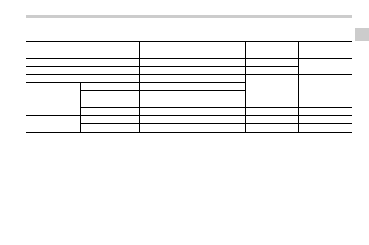
(51,1)
北米Model "A1700BE-B" EDITED: 2017/ 10/ 11
& Components that will operate with the seatbelt pretensioner(s) simultaneously
Cases
Frontal collision
Side collision Rollover accident
Components
Offset frontal collision Other frontal collision
Seatbelt pretensioner for driver ***
*2*3
*
Shoulder belt pretensioner for front passenger ***
*3*4
Lap belt pretensioner for front passenger **
––
SRS frontal airbag
For driver **
For front passenger
*1
**
SRS curtain airbag
Impacted side * – **
Non-impacted side * ––*
SRS side airbag
Impacted side ––*
*5
–
Non-impacted side –––
–
*: Operate
–: Not operate
*1
: This does not operate if the occupant detections system deactivates airbag operation. For details, refer to “Front passenger’s SRS frontal airbag” F1-43
*2
: This operates when both the satellite safing sensor and driver’s side front door impact sensor sense an impact force.
*3
: These do not operate when a center pillar impact sensor detects a signal faster than the front door impact sensor, or both sensors detect signals
simultaneously.
*4
: This operates when both the satellite safing sensor and the front passenger’s side front door impact sensor sense an impact force.
*5
: This operates when both the satellite safing sensor and any of the center pillar impact sensors/front door impact sensors sense an impact force.
– CONTINUED –
Seat, seatbelt and SRS airbags/Front seatbelt pretensioners
1-19
1
(52,1)
北米Model "A1700BE-B" EDITED: 2017/ 10/ 11
& Safety tips
. Pretensioners are designed to function
on a one-time-only basis. If a pretensioner
is activated, have both front seatbelt
retractor assemblies replaced only by an
authorized SUBARU dealer. When repla-
cing seatbelt retractor assemblies, use
only genuine SUBARU parts.
. If either front seatbelt does not retract or
cannot be pulled out due to a malfunction
or activation of the pretensioner, contact
your SUBARU dealer as soon as possible.
. If the front seatbelt retractor assembly
or surrounding area has been damaged,
contact your SUBARU dealer as soon as
possible.
. When you sell your vehicle, we urge
you to inform the buyer that the vehicle is
equipped with seatbelt pretensioners.
Also, notify the buyer of the contents of
this section.
& System monitors
A diagnostic system continually monitors
the readiness of the seatbelt pretensioner
with the ignition switch in the “ON” position.
The seatbelt pretensioners share the
control module with the SRS airbag
system. Therefore, if any malfunction
occurs in a seatbelt pretensioner, the
SRS airbag system warning light will
illuminate. For details, refer to “SRS airbag
system monitors” F1-62.
& System servicing
WARNING
. When discarding a seatbelt re-
tractor assembly or scrapping
the entire vehicle damaged by a
collision, consult your SUBARU
dealer.
. Tampering with or disconnecting
the system’s wiring could result
in accidental activation of the
seatbelt pretensioner and/or
SRS airbag or could make the
system inoperative, which may
result in serious injury. Do not
use electrical test equipment on
any circuit related to the seatbelt
pretensioner and SRS airbag sys-
tems. For required servicing of
the seatbelt pretensioner, con-
sult your nearest SUBARU deal-
er.
CAUTION
The sensors and SRS airbag control
modules are located in the following
locations.
. Front sub sensors: on both the
right and left side at the front of
the vehicle
. Front door impact sensors: on
both front doors
. Satellite safing sensor: under the
rear center seat
. Si de airbag sensors: on both
center pillars
. Curtain airbag sensors: on both
rear wheel houses
. SRS airbag control module (in-
cluding the impact sensors): un-
der the center of the instrument
panel
If you need service or repair in those
areas or near the front seatbelt
retractors, have the work performed
by your authorized SUBARU dealer.
NOTE
If the front or side part of the vehicle is
damaged in an accident to the extent
that the seatbelt pretensioner does not
operate, contact your SUBARU dealer
as soon as possible.
Seat, seatbelt and SRS airbags/Front seatbelt pretensioners
1-20
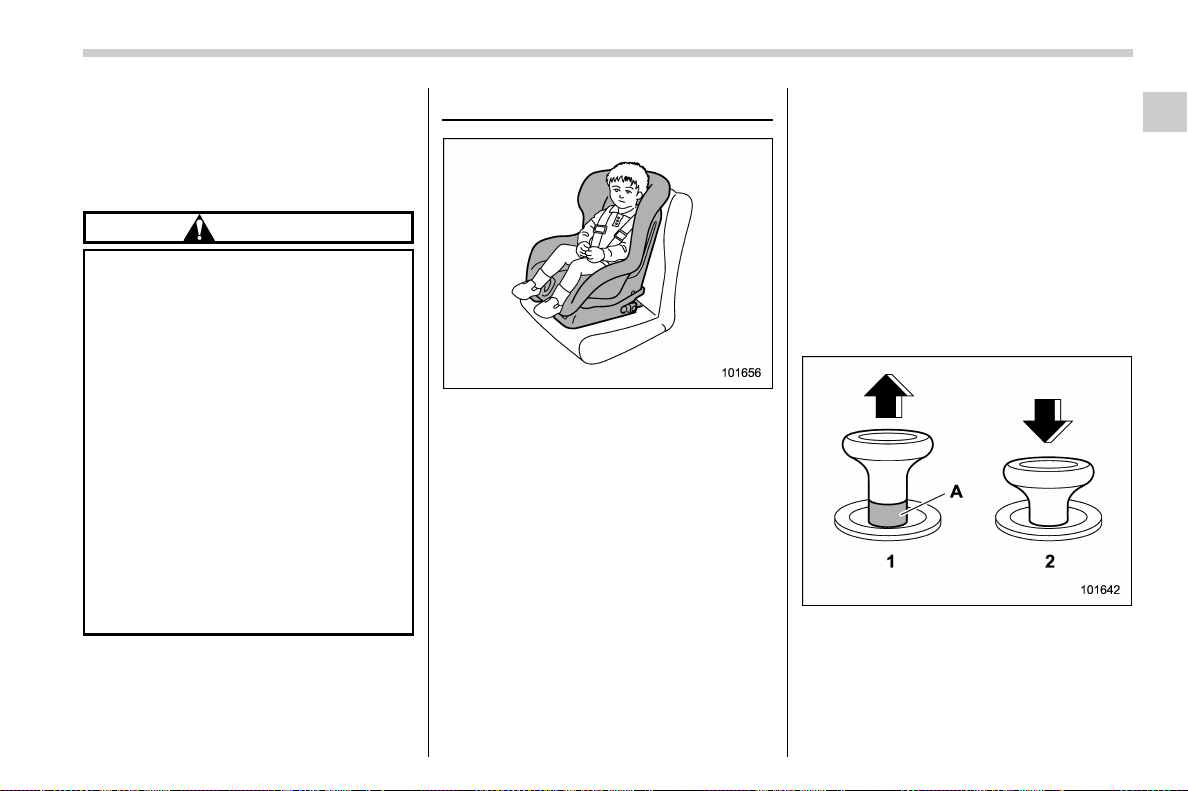
(53,1)
北米Model "A1700BE-B" EDITED: 2017/ 10/ 11
& Precautions against vehicle
modification
Always consult your SUBARU dealer if you
want to install any accessory parts to your
vehicle.
CAUTION
Do not perform any of the following
modifications. Such modifications
can interfere with proper operation
of the seatbelt pretensioners.
. Att achment of any equipm ent
(bush bar, winches, snow plow,
skid plate, etc.) other than genu-
ine SUBARU accessory parts to
the front end.
. Modification of the suspension
system or front end structure.
. Installation of a tire of different
size and construction from the
tires specified on the vehicle
placard attached to the driver’s
door pillar or specified for indivi-
dual vehicle models in this Own-
er ’s Manual.
Child restraint systems
Infants and small children should always
be placed in an infant or child restraint
system in the rear seat while riding in the
vehicle. You should use an infant or child
restraint system that meets Federal Motor
Vehicle Safety Standards or Canada Mo-
tor Vehicle Safety Standards, is compati-
ble with your vehicle and is appropriate for
the child’s age and size. All child restraint
systems are designed to be secured in
vehicle seats by lap belts or the lap belt
portion of a lap/shoulder belt (except those
described in “Installation of child restraint
systems by use of lower and tether
anchorages (LATCH)” F1-30).
Children cou ld be endan gered in an
accident if their child restraints are not
properly secured in the vehicle. When
installing the child restraint system, care-
fully follow the manufacturer’s instructions.
According to accident statistics, children
are safer when properly restrained in the
rear seating positions than in the front
seating positions.
All U.S. states and Canadian provinces
require that infants and small children be
restrained in an approved child restraint
system at all times while the vehicle is
moving.
Lock release knob
1) Unlocked
2) Locked
A) Unlocking marker in red
– CONTINUED –
Seat, seatbelt and SRS airbags/Child restraint systems
1-21
1
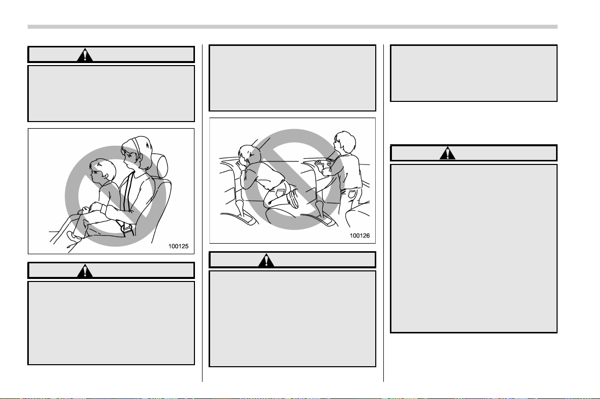
(54,1)
北米Model "A1700BE-B" EDITED: 2017/ 10/ 11
WARNING
Before installing a child restraint
system, be sure to confirm that the
seatback is securely locked into
place. Otherwise, in an accident,
serious injury or death could result.
WARNING
Never let a passenger hold a child on
his or her lap or in his or her arms
while the vehicle is moving. Th e
passenger cannot protect the child
from injury in a collision, because
the child will be caught between the
passenger and objects inside the
vehicle.
Additionally, holding a child in your
lap or arms in the front seat exposes
that child to another serious danger.
Since the SRS airbag deploys with
considerable speed and force, the
child could be injured or even killed.
WARNING
Children should be properly re-
strained at all times. Never allow a
child to stand up, or to kneel on any
seat. Unrestrained children will be
thrown forward during sudden stop
or in an accident and can be injured
seriously.
Additionally, children standing up or
kneeling on or in front of the front
seat are exposed another serious
danger. Since the SRS airbag de-
ploys with considerable speed and
force, the child could be injured or
even killed.
& Safety tips for installing child
restraint systems
WARNING
. Child restraint systems and seat-
belts can become hot in a vehicle
that has been closed up in sunny
weather; they could burn a small
child. Check the child restraint
system before you place a child
in it.
. Do not leave an unsecured child
restraint system in your vehicle.
Unsecured child restraint sys-
tems can be thrown around in-
side of the vehicle in a sudden
stop, turn or accident; they can
strike and injure vehicle occu-
pants as well as result in serious
injuries or death to the child.
Seat, seatbelt and SRS airbags/Child restraint systems
1-22

(55,1)
北米Model "A1700BE-B" EDITED: 2017/ 10/ 11
CAUTION
When you install a child restraint
system, follow the manufacturer’s
instructions supplied with it. After
installing the child restraint system,
check to ensure that it is held
securely in position. If it is not held
tight and secure, the danger of your
child suffering personal injury in the
event of an accident may be in-
creased.
& Where to place a child re-
straint system
The following are SUBARU’s recommen-
dations on where to place a child restraint
system in your vehicle.
A: Front passenger’s seat
You should not install a child restraint
system (including a booster seat) due to
the hazard to children posed by the
passenger’s airbag.
B: Rear sea t, window-si de seating
positions
Recommended positions for all types of
child restraint systems.
In these positions, the following equipment
is provided for installing a child restraint
system.
. Au tomatic Locking Retractor/Emer-
gency Locking Retractor (ALR/ELR) seat-
belts
. Lower anchorages (bars)
. Upper anchorages (tether anchorages)
Some types of child restraints might not be
able to be secured firmly due to projection
of the seat cushion.
In this seating position, you should use
only a child restraint system that has a
bottom base that fits snugly against the
contours of the seat cushion and can be
securely retained using the seatbelt.
C: Rear seat, center seating position
The ALR/ELR seatbelt and an upper
anchorage (tether anchorage, if equipped)
are provided in this position.
Some types of child restraints might not be
able to be secured firmly due to projection
of the seat cushion.
In this seating position, you should use
only a child restraint system that has a
bottom base that fits snugly against the
contours of the seat cushion and can be
securely retained using the seatbelt.
When you install a child restraint system in
the rear seat’s center seating position,
raise the center head restraint.
Lower anchorages (bars) for window-side
seating positions may be used for a seat in
the center se ating pos ition if a ch ild
– CONTINUED –
Seat, seatbelt and SRS airbags/Child restraint systems
1-23
1
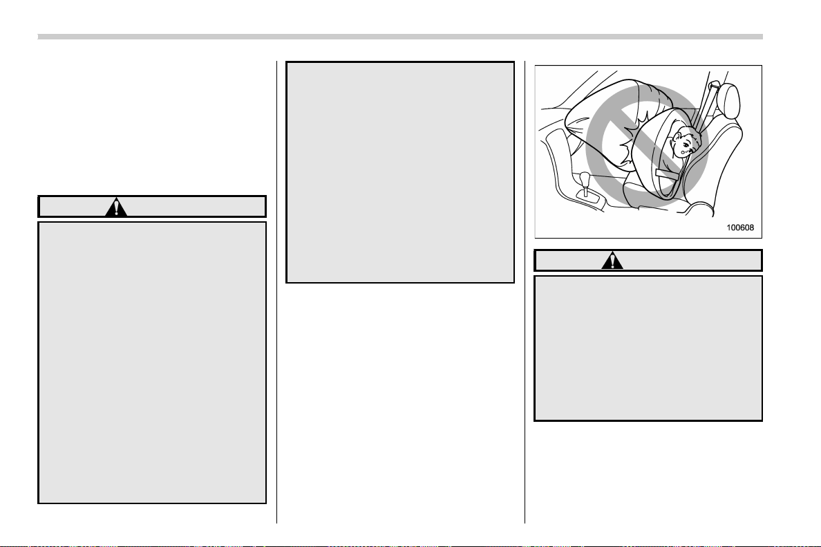
(56,1)
北米Model "A1700BE-B" EDITED: 2017/ 10/ 11
restraint system manufacturer’s instruc-
tions permit and specify using anchors as
far apart as those in this vehicle.
If a child restraint system is not correctly
fixed in place (for example, if a child
restraint system can be moved more than
1 inch (2.5 cm) from side to side), you
should install the child restraint system in a
rear seat, window-side seating position.
WARNING
. Even with advanced airbags, chil-
dren can be seriously injured by
the airbag. Place children in the
rear seat properly restrained at
all times. The SRS airbag deploys
with considerable speed and
force and can injure or even kill
children, especially if they are not
restrained or improperly re-
strained. Beca use children are
lighter and weaker than adults,
their risk of being injured from
deployment is greater.
For that reason, be sure to secure
ALL types of child restraint de-
vices (including forward facing
child seats) in the REAR seats at
all times. You should choose a
restraint device which is appro-
priate for the child’s age, height
and weight. According to acci-
dent statistics, children are safer
when properly restrained in the
rear seating positions than in the
front seating positions.
. Do not use lower anchorages
(bars) for a seat in the center
seating position unless a child
restraint system manufacturer’s
instructions permit and specify
using anchors spaced a s far
apart as those in this vehicle.
. Do not connect two or more lower
hooks onto the same anchorage
(bar).
WARNING
SINCE YOUR VEHICLE IS
EQUIPPED WITH A PASSENGER’S
SRS AIRBAG, NEVER INSTALL A
FORWARD OR REARWARD FACING
CHILD SAFETY SEAT IN THE FRONT
PASSENGER’S SEAT. DOING SO
RISKS SERIOUS INJURY OR DEATH
TO THE CHILD BY PLACING THE
CHILD’S HEAD TOO CLOSE TO THE
SRS AIRBAG.
Seat, seatbelt and SRS airbags/Child restraint systems
1-24
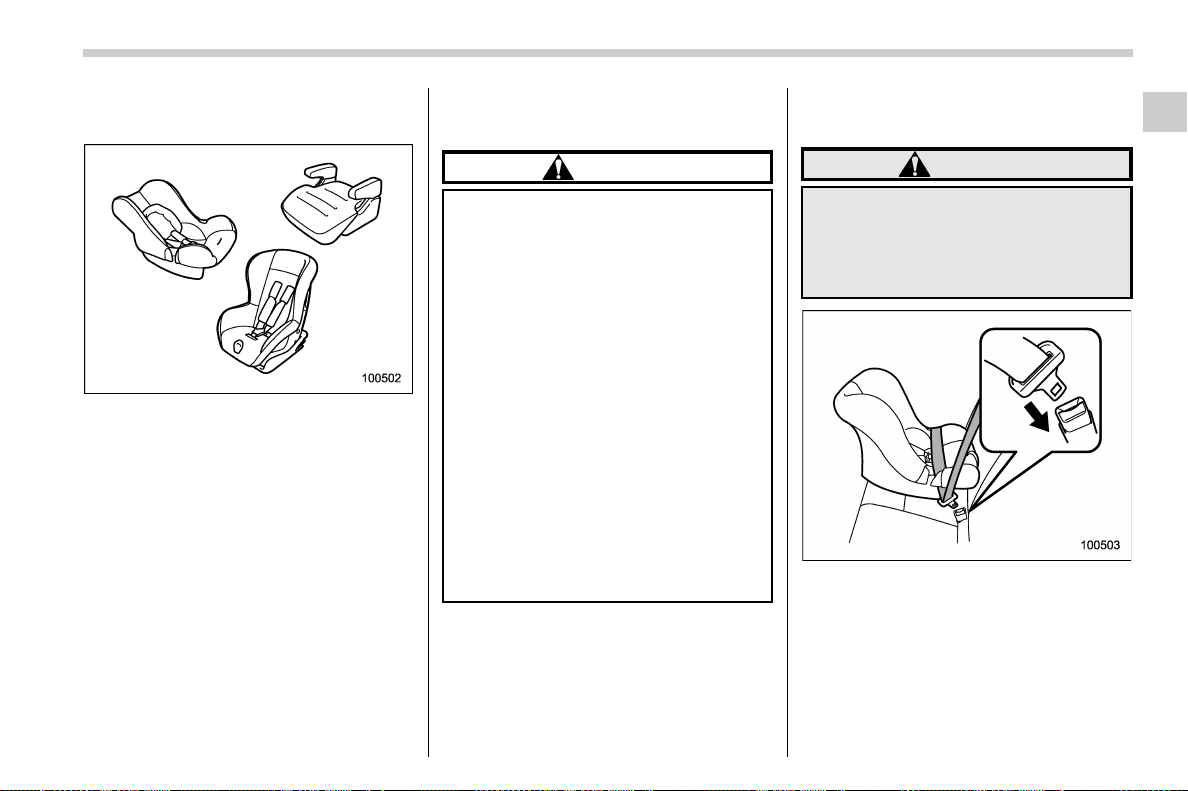
(57,1)
北米Model "A1700BE-B" EDITED: 2017/ 10/ 11
& Choosing a child restraint
system
Choose a child restraint system that is
appropriate for the child’s age and size
(weight and height) in order to provide the
child with proper protection. The child
restraint system should meet all applicable
requirements o f Federal Motor Vehicle
Safety Standards for the United States or
of Canada Motor Vehicle Safety Standards
for Canada. It can be identified by looking
for the label on the child restraint system or
the manufacturer’s statement of compli-
ance in the document attached to the
system.
Also it is important for you to make sure
that the child restraint system is compa-
tible with the vehicle in which it will be
used.
& Installing child restraint sys-
tems with ALR/ELR seatbelt
CAUTION
. When you install a child restraint
system, follow the manufac-
turer’s instructions supplied with
it. After installing the child re-
straint system, check to ensure
that it is held securely in position.
If it is not held tight and secure,
the danger of your child suffering
personal injury in the event of an
accident may be increased.
. When installing a child restraint
system in the rear center seating
position, set both seatbacks to
the original position. Otherwise,
the child restraint system cannot
be securely restrained, which
may result in death or serious
injuries in the event of sudden
stop, sudden steering maneuver
or an accident.
! Installing a rearward facing child
restraint
WARNING
Before installing a child restraint
system, be sure to confirm that the
seatback is securely l ocked into
place. Otherwise, i n an accident,
serious injury or death could result.
1. Shake the seatback to confirm that it is
securely locked into place.
– Check the red colored unlocking
marker which is attached to the bottom
of the lock release knob is not visible.
For details, refer to “Folding down the
rear seatback” F1-10.
2. Place the child restraint system in the
– CONTINUED –
Seat, seatbelt and SRS airbags/Child restraint systems
1-25
1
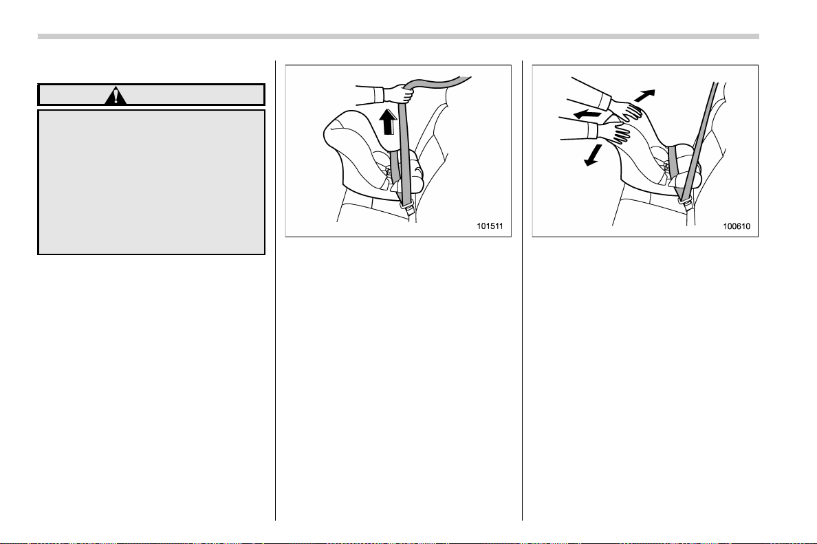
(58,1)
北米Model "A1700BE-B" EDITED: 2017/ 10/ 11
rear seating position.
WARNING
When you intend to install a child
restraint system in the rear center
seating position, if the child restraint
system does not fit snugly against
the contours of the rear center seat
cushion, install the child restraint
system in the window-side seating
position to be safe. For details, refer
to “Where to place a child restraint
system” F1-23.
3. Run the lap and shoulder belt through
or around the child restraint system follow-
ing the instructions provided by its manu-
facturer.
4. Insert the tongue plate into the buckle
until you hear a click.
5. Take up the slack in the lap belt.
6. If using the seatbelt in the ALR mode is
recommended by the manufacturer’s in-
structions supplied with the child restraint
system, perform the following procedure.
(1) Pull out the seatbelt fully from the
retractor to change the retractor over from
the Emergency Locking Retractor (ELR) to
the Automatic Locking Retractor (ALR)
mode.
(2) Allow the belt to rewind into the
retractor. As the belt is rewinding, clicks
will be heard which indicate the retractor
functions as ALR.
7. Push and pull the child restraint system
forward and from side to side to check if it
is firmly secured. Sometimes a child
restraint can be more firmly secured by
pushing it down into the seat cushion and
then tightening the seatbelt.
8. If the seatbelt has been set to the ALR
mode in step 6, pull at the shoulder portion
of the belt to confirm that it cannot be
pulled out (ALR properly functioning).
Seat, seatbelt and SRS airbags/Child restraint systems
1-26
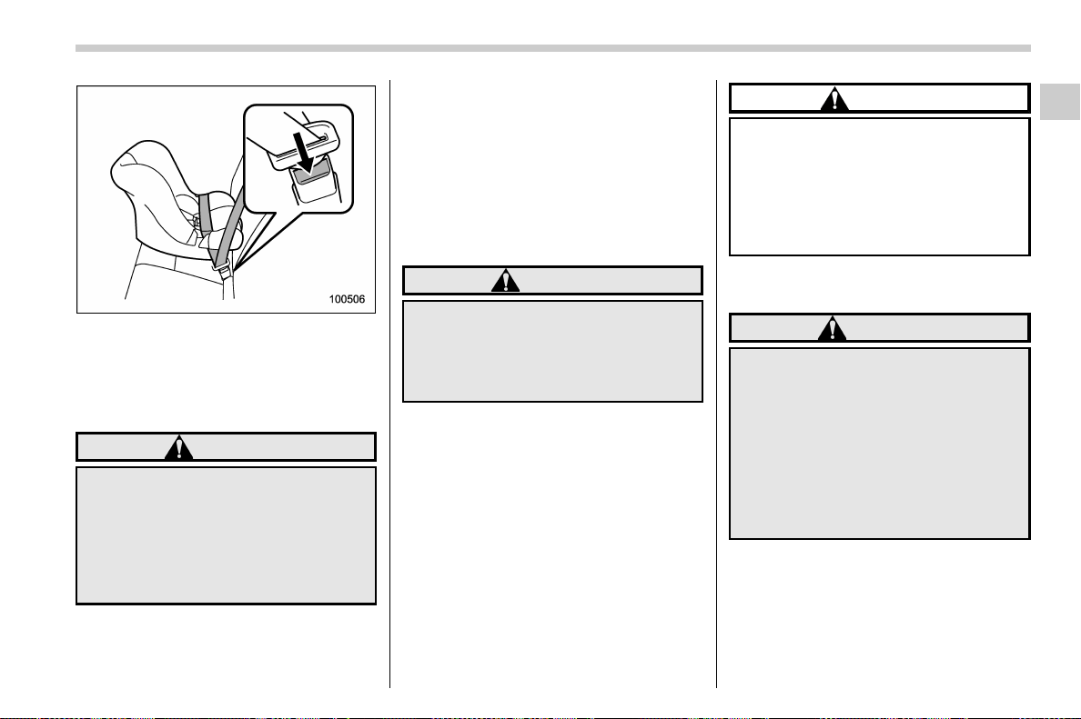
(59,1)
北米Model "A1700BE-B" EDITED: 2017/ 10/ 11
9. To remove the child restraint system,
press the release button on the seatbelt
buckle and allow the belt to retract
completely. The belt will return to the
ELR mode.
WARNING
NEVER INSTALL A FORWARD OR
REARWARD FACING CHILD SEAT IN
THE FRONT PASSENGER’S SEAT.
DOING SO RISKS SERIOUS INJURY
OR DEATH TO THE CHILD BY PLA-
CING THE CHI LD’SHEADTOO
CLOSE TO THE SRS AIRBAG.
NOTE
When the child restraint system is no
longer in use, remove it and restore the
ELR function of the retractor. That
function is restored by allowing the
seatbelt to retract fully.
! Installing forward facing child re-
straint
WARNING
Before installing a child rest raint
system, be sure to confirm that the
seatback is securel y locked into
place. Otherwise, in an accident,
serious injury or death could result.
1. Shake the seatback to confirm that it is
securely locked into place.
– Check the red colored unlocking
marker which is attached to the bottom
of the lock release knob is not visible.
For details, refer to “Folding down the
rear seatback” F1-10.
2. Remove the head restraint of the rear
seating position where the child restraint
system is to be installed. For details, refer
to “Head restraint adjustment” F1-8.
CAUTION
Store the head restraint that has
been removed in the trunk. Avoid
placing the head restraint in the
passenger compartment to prevent
it from being thrown around in the
passenger compartment in a sud-
den stop or a sharp turn.
3. Place the child restraint system in the
rear seating position.
WARNING
When you intend to install a child
restraint system in the rear center
seating position, if the child restraint
system does not fit snugly against
the contours of the rear center seat
cushion, install the child restraint
system in the window-side seating
position to be safe. For details, refer
to “Where to place a child restraint
system” F1-23.
– CONTINUED –
Seat, seatbelt and SRS airbags/Child restraint systems
1-27
1
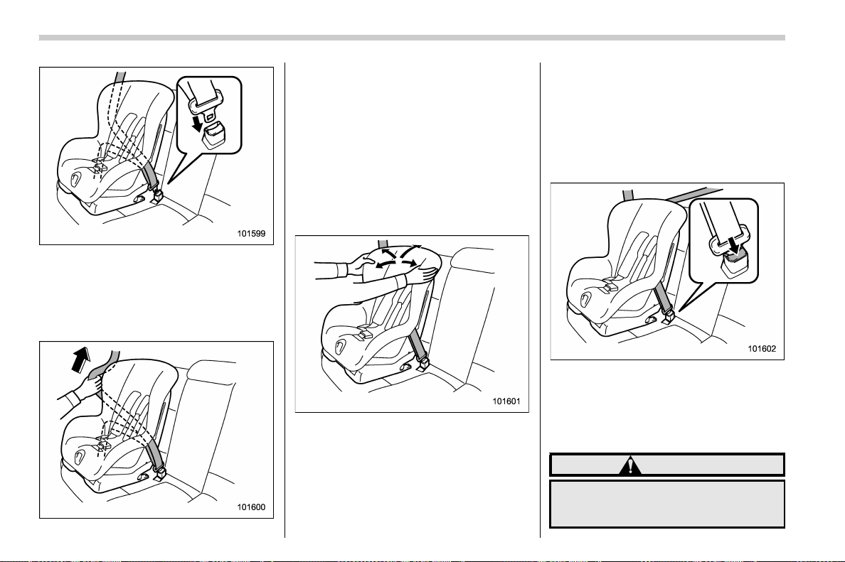
(60,1)
北米Model "A1700BE-B" EDITED: 2017/ 10/ 11
4. Run the lap and shoulder belt through
or around the child restraint system follow-
ing the instructions provided by its manu-
facturer.
5. Insert the tongue plate into the buckle
until you hear a click.
6. Take up the slack in the lap belt.
7. Perform the following procedure.
(1) Pull out the seatbelt fully from the
retractor to change the retractor over
from the Emergency Locking Retractor
(ELR) to the Automatic Locking Re-
tractor (ALR) mode.
(2) Allow the belt to rewind into the
retractor. As the belt is rewinding,
clicks will be heard which indicate the
retractor functions as ALR.
8. Before having a child sit in the child
restraint system, try to move it back and
forth and right and left to check if it is firmly
secured. Sometimes a child restraint
system can be more firmly secured by
pushing it down into the seat cushion and
then tightening the seatbelt.
9. Pull at the shoulder portion of the belt
to confirm that it cannot be pulled out (ALR
properly functioning).
10. Latch the top tether hook onto the
tether anchorage that is located behind the
rear seat and tighten the top tether firmly.
For additional instructions, refer to “To p
tether anchorages” F1-32.
11. To remove the child restraint system,
press the release button on the seatbelt
buckle and al low the belt to retr act
completely. The belt will retur n to the
ELR mode.
WARNING
NEVER INSTALL A FORWARD OR
REARWARD FACING CHILD SEAT IN
THE FRONT PASSENGER’S SEAT.
Seat, seatbelt and SRS airbags/Child restraint systems
1-28
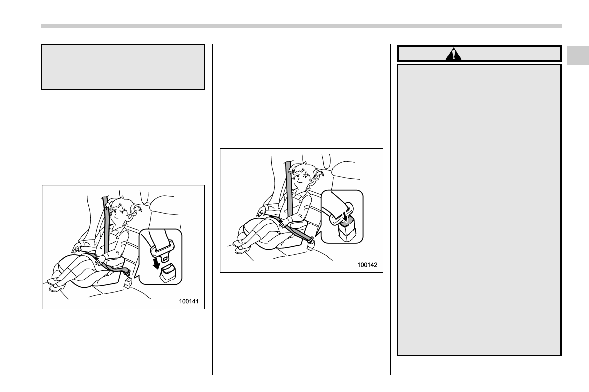
(61,1)
北米Model "A1700BE-B" EDITED: 2017/ 10/ 11
DOING SO RISKS SERIOUS INJURY
OR DEATH TO THE CHILD BY PLA-
CING THE CHI LD’SHEADTOO
CLOSE TO THE SRS AIRBAG.
NOTE
When the child restraint system is no
longer in use, remove it and restore the
ELR function of the retractor. That
function is restored by allowing the
seatbelt to retract fully.
& Installing a booster seat
1. Place the booster seat in the rear
seating position and sit the child on it.
The child should sit well back on the
booster seat.
2. Run the lap and shoulder belt through
or around the booster seat and the child
following the instructions provided by its
manufacturer.
3. Insert the tongue plate into the buckle
until you hear a click. Take care not to twist
the seatbelt.
Make sure the shoulder belt is positioned
across the center of child’s shoulder and
that the lap belt is positioned as low as
possible on the child’s hips.
4. To remove the booster seat, press the
release button on the seatbelt buckle and
allow the belt to retract.
WARNING
. Never use a belt that is twisted or
reversed. In an accident, this can
increase the risk or severity of
injury to the child.
. Never place the shoulder belt
under the child’s arm or behind
the child’s back. If an accident
occurs, this can increase the risk
or severity of injury to the child.
. The seatbelt should fit snugly in
order to provide full restraint.
Loose fitting belts are not as
effective in preventing or redu-
cing injury.
. Place the lap belt as low as
possible on the child’s hips. A
high-positioned lap belt will in-
crease the risk of sliding under
the lap belt and of the lap belt
sliding up over the abdomen, and
both can result in serious internal
injury or death.
. Make sure the shoulder belt is
positioned across the center of
child’s shoulder. Placing the
shoulder belt over the neck may
result in neck injury during sud-
den braking or in a collision.
– CONTINUED –
Seat, seatbelt and SRS airbags/Child restraint systems
1-29
1
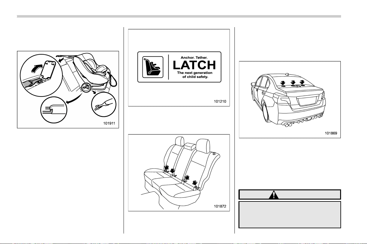
(62,1)
北米Model "A1700BE-B" EDITED: 2017/ 10/ 11
& Installation of child restraint
systems by use of lower and
tether anchorages (LATCH)
Some types of child restraint systems can
be installed on the rear seat of your vehicle
without use of the seatbelts. Such child
restraint systems are secured to the
designated anchorages provided on the
vehicle body. The lower and tether an-
chorages are sometimes referred to as the
LATCH system (Lower Anchors and
Tethers for CHildren).
Your vehicle is equipped with four lower
anchorages (bars) and three upper an-
chorages (tether anchorages) for accom-
modating such child restraint systems.
The lower anchorages (bars) are used for
installing a child restraint system only in
the rear seat window-side seating posi-
tions. For each window-side seating posi-
tion, two lower anchorages are provided.
Each lower anchorage is located behind
the cover of the seatback bottom.
The tether anchorages (upper an-
chorages) are provided at the locations
shown in the above illustration. For details,
refer to “Top tether anchorages” F1-32.
To install a child restraint system using
lower and tether anchorages, perform the
following procedure.
WARNING
Before installing a child restraint
system, be sure to confirm that the
seatback is securely l ocked into
place. Otherwise, i n an accident,
Seat, seatbelt and SRS airbags/Child restraint systems
1-30
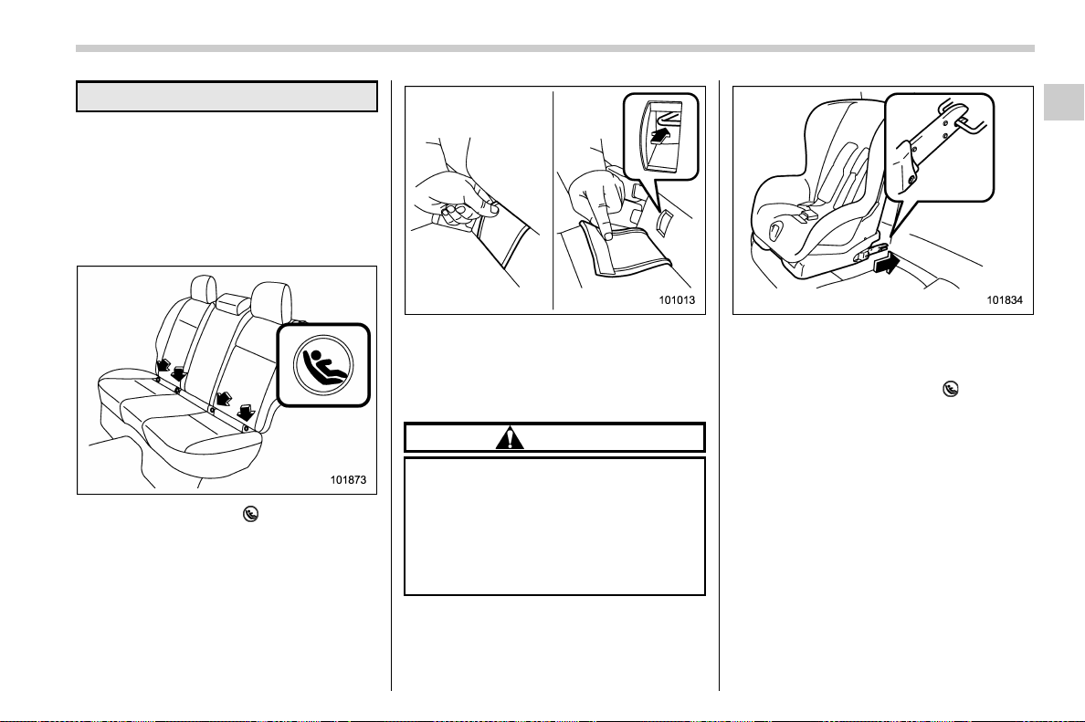
(63,1)
北米Model "A1700BE-B" EDITED: 2017/ 10/ 11
serious injury or death could result.
1. Shake the seatback to confirm that it is
securely locked into place.
– Check the red colored unlocking
marker which is attached to the bottom
of the lock release knob is not visible.
For details, refer to “Folding down the
rear seatback” F1-10.
2. You will find marks “ ” at the bottom of
the rear seat seatbacks. These marks
indicate the positions of the lower an-
chorages (bars).
Remove the covers and locate the lower
anchorages (bars).
3. Remove the rear seat head restraint.
For details, refer to “Head restraint adjust-
ment” F1-8.
CAUTION
Store the head restraint that has
been removed in the trunk. Avoid
placing the head restraint in the
passenger compartment to prevent
it from being thrown around in the
passenger compartment in a sud-
den stop or a sharp turn.
4. While following the instructions sup-
plied by the child restraint system manu-
facturer, connect the lower hooks onto the
lower anchorages located at “
” marks on
the bottom of the rear seatback. When the
hooks are connected, make sure the
adjacent seatbelts are not caught.
– CONTINUED –
Seat, seatbelt and SRS airbags/Child restraint systems
1-31
1
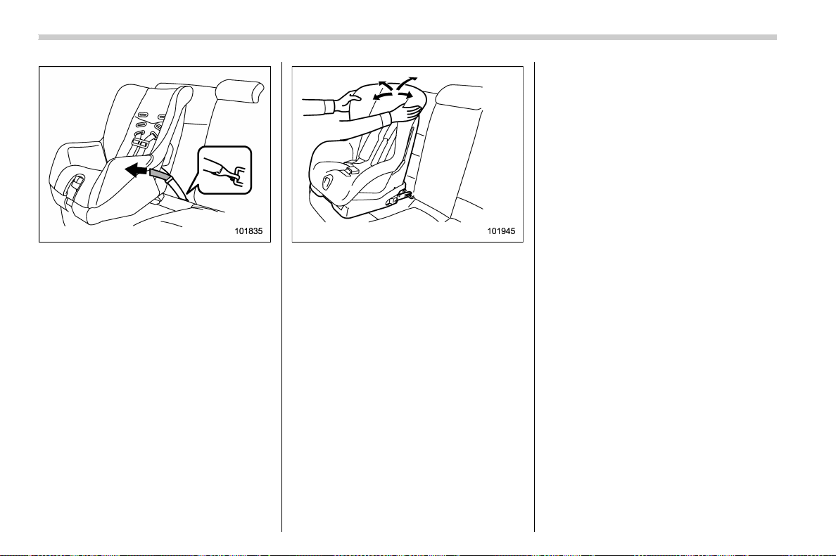
(64,1)
北米Model "A1700BE-B" EDITED: 2017/ 10/ 11
5. [If your child restraint system is of a
flexible attachment type (which uses tether
belts to connect the child restraint system
properly to the lower anchorages)]
While pushing the child restraint into the
seat cushion, pull both left and right lower
tether belts up to secure the child restraint
system firmly by taking up the slack in the
belt.
6. Latch the top tether hook onto the
tether anchorage that is located on the rear
shelf and tighten the top tether firmly. For
additional instructions, refer to “Top tether
anchorages” F1-32.
7. Before seating a child in the child
restraint system, try to move it back and
forth and right and left to verify that it is held
securely in position.
8. To remove the child restraint system,
follow the reverse procedures of installa-
tion.
If you have any question concerning this
type of child restraint system, ask your
SUBARU dealer.
& Top tether anchorages
Your vehicle is equipped with three top
tether anchorages so that a child restraint
system having a top tether can be installed
in the rear seat. When installing a child
restraint system using top tether, proceed
as follows, while observing the instructions
by the child restraint system manufacturer.
Since a top tether can provide additional
stability by offering another connection
between a child restraint system and the
vehicle, we recommend that you use a top
tether whenever one is required or avail-
able.
Seat, seatbelt and SRS airbags/Child restraint systems
1-32
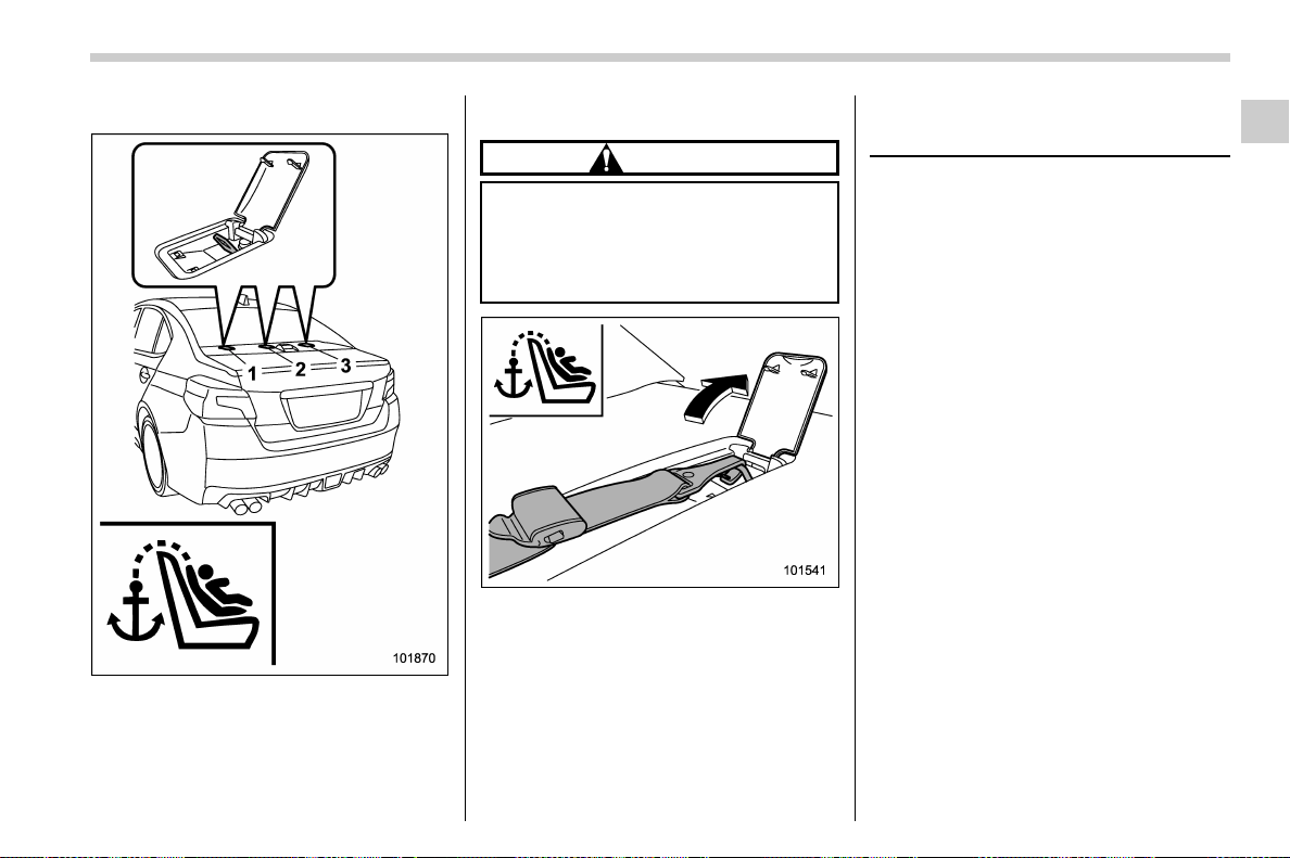
(65,1)
北米Model "A1700BE-B" EDITED: 2017/ 10/ 11
! Anchorage location
1) For left seat
2) For center seat
3) For right seat
These upper anchorages are installed on
the rear shelf behind the rear seat.
! To hook the top tether
CAUTION
Remove the head restraint when
mounting a child restraint system.
Otherwise, it might be possible that
the top tether cannot be fastened
tightly.
1. Open the cover and attach the top
tether hook to the appropriate upper
anchorage.
2. Tighten the top tether securely.
Please contact your SUBARU dealer if you
have any question regarding the installa-
tion of a child restraint system.
*SRS airbag (Supplemental
Restraint System airbag)
*SRS: This stands for supplemental re-
straint system. This name is used because
the airbag system supplements the vehi-
cle’s seatbelts.
Your vehicle is equipped with a supple-
mental restraint system in addition to a lap/
shoulder belt at each front seating position
and each rear window-side seating posi-
tions. The supplemental restraint system
(SRS) consists of the following airbags:
. Driver’s and front passenger’s frontal
airbags
. Driver’s and front passenger’s side
airbags
. Curtain airbags (for driver, front pas-
senger, and window-side rear passen-
gers)
. Knee airbag for driver
These SRS airbags are designed only
as a supplement to the primary protec-
tion provided by the seatbelt.
The system also controls front seatbelt
pretensioners. For operation instructions
and precautions concerning the seatbelt
pretensioner, refer to “Front seatbelt pre-
tensioners” F1-17.
– CONTINUED –
Seat, seatbelt and SRS airbags/*SRS airbag (Supplemental Restraint System airbag)
1-33
1
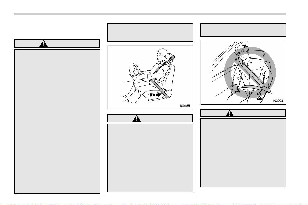
(66,1)
北米Model "A1700BE-B" EDITED: 2017/ 10/ 11
& General precautions regard-
ing SRS airbag system
WARNING
. To obtain maximum protection in
the event of an accident, the
driver and all passengers must
always wear seatbelts when in
the vehicle. The SRS airbag is
designed only to be a supplement
to the primary protection pro-
vided by the seatbelt. It does not
eliminate the need to fasten seat-
belts. In combination with the
seatbelts, it offers the best com-
bined protection in case of a
serious accident.
Not wearing a seatbelt increases
the chance of severe injury or
death in a crash even when the
vehicle has the SRS airbag.
For instructions and precautions
concerning the seatbelt system,
refer to “Seatbelts” F1-12.
. The SRS side airbag and SRS
curtain airbag are designed only
to be a supplement to the primary
protection provided by the seat-
belt. They do not eliminate the
need to fasten seatbelts. It is also
important to wear your seatbelt to
help avoid injuries that can result
when an occupant is not seated
in a proper upright position.
WARNING
. The SRS airbags deploy with
considerable speed and force.
Occupants who are out of proper
position when the SRS airbag
deploys could suffer very serious
injuries. Because the SRS airbag
needs enough space for deploy-
ment, the driver should always sit
upright and well back in the seat
as far from the steering wheel as
practical while still maintaining
full vehicle control and the front
passenger should move the seat
as far back as possible and sit
upright and well back in the seat.
WARNING
. Do not sit or lean unnecessarily
close to either front door. The
SRS side airbags are stored in
both front seat seatbacks next to
the door, and they provide pro-
tection by deploying rapidly (fas-
ter than the blink of an eye) in the
event of a side impact or frontal
collision. However, the force of
SRS side airbag deployment may
cause injuries if your head or
other parts of the body are too
close to the SRS side airbag.
Seat, seatbelt and SRS airbags/*SRS airbag (Supplemental Restraint System airbag)
1-34
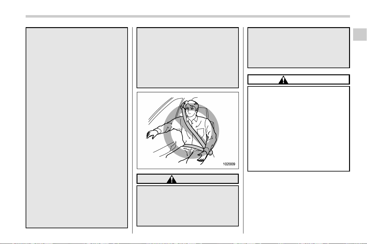
(67,1)
北米Model "A1700BE-B" EDITED: 2017/ 10/ 11
. Since your vehicle is equipped
with SRS curtain airbags, do not
sit or lean unnecessarily close to
the front or rear door on either
side. Also, do not put your head,
arms or hands out of the window.
The SRS curtain airbags on both
sides of the cabin are stored in
the roof side (between the front
pillar and a point behind the rear
quarter glass), and they provide
protection by deploying rapidly
(faster than the blink of an eye) in
the event of a side impact, roll-
over or an offset frontal collision.
However, the force of its deploy-
ment may cause injuries if your
head is too close to it.
. Do not sit or lean unnecessarily
close to the SRS airbag. Because
the SRS airbag deploys with
considerable speed – faster than
the blink of an eye – and force to
protect in high speed collisions,
the force of an airbag can injure
an occupant whose body is too
close to SRS airbag.
It is also important to wear your
seatbelt to help avoid injuries
that can result when the SRS
airbag contacts an occupant not
in proper position such as one
thrown forward during pre-acci-
dent braking.
Even when properly positioned,
there remains a possibility that
an occupant may suffer minor
injury such as abrasions and
bruises to the face or arms be-
cause of the SRS airbag deploy-
ment force.
WARNING
. Do not rest your arm on either
front door or its internal trim. You
could be injured in the event of
SRS side airbag deployment.
. Do not place any objects over or
near the SRS airbag cover or
between you and the SRS airbag.
If the SRS airbag deploys, these
objects could interfere with its
proper operation and could be
propelled inside the vehicle,
causing injury.
CAUTION
. When the SRS airbag deploys,
some smoke will be released.
This smoke could cause breath-
ing problems for people with a
history of asthma or other breath-
ing trouble. If you or your pas-
sengers have breathing pro-
blems after SRS airbag deploys,
get fresh air promptly.
. A deploying SRS airbag releases
hot gas. Occupants could get
burned if they come into direct
contact with the hot gas.
NOTE
. When you sell your vehicle, we urge
you to inform the buyer that the vehicle
is equipped with SRS airbags. Also,
notify the buyer of the applicable sec-
tion of this Owner’s Manual.
. If the SRS airbag deploys, fuel
supply will be cut off to reduce the risk
– CONTINUED –
Seat, seatbelt and SRS airbags/*SRS airbag (Supplemental Restraint System airbag)
1-35
1
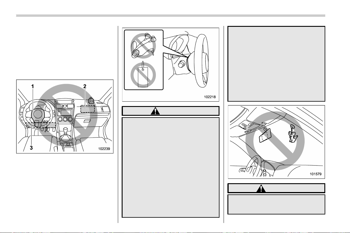
(68,1)
北米Model "A1700BE-B" EDITED: 2017/ 10/ 11
of fire caused by leaking fuel. For
details about restarting of the engine,
refer to “If your vehicle is involved in an
accident” F9-28.
& General precautions regard-
ing SRS airbag system for
accessories and any objects
Do not put any objects over/under the
following parts.
1) Over the steering wheel pad
2) Over the dashboard
3) Under the driver’s side of the instrument
panel
WARNING
. Do not put any objects (including
straps or cords) over the steering
wheel pad, column cover, or
dashboard.
– These objects could be en-
tangled with the steering
wheel, preventing the SRS
frontal airbag, etc. from oper-
ating properly.
– If the SRS frontal airbag de-
ploys, these objects could be
propelled inside the vehicle,
causing injury.
. Do not put any objects under the
driver’s side of the instrument
panel. If the SRS knee airbag
deploys, those objects could in-
terfere with its proper operation
and could be propelled inside the
vehicle, causing injury.
. The key must not be attached to
heavy, sharp or hard acces-
sories, or another key. If the SRS
knee airbag deploys, those ob-
jects could interfere with its
proper operation and could be
propelled inside the vehicle and
cause injury.
WARNING
Do not attach accessories to the
windshield, or fit an extra-wide mir-
ror over the inside rear view mirror. If
Seat, seatbelt and SRS airbags/*SRS airbag (Supplemental Restraint System airbag)
1-36
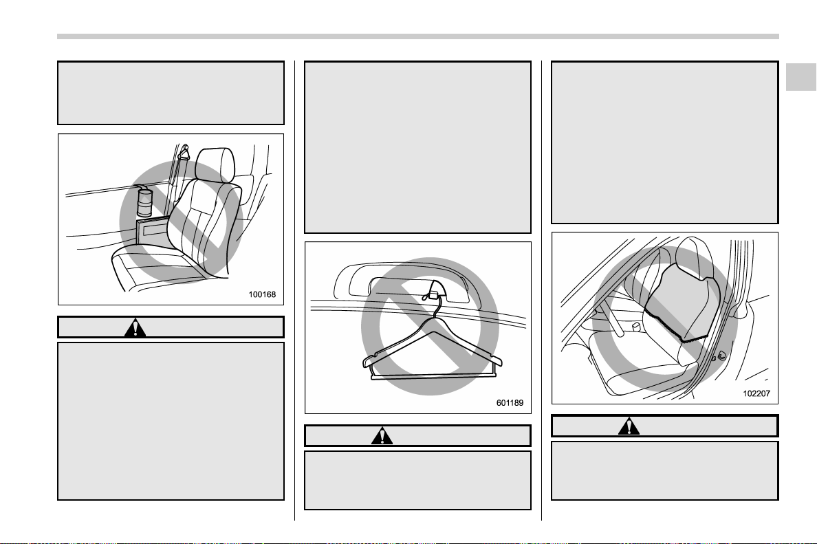
(69,1)
北米Model "A1700BE-B" EDITED: 2017/ 10/ 11
the SRS airbag deploys, those ob-
jects could become projectiles that
could seriously injure vehicle occu-
pants.
WARNING
. Do not attach accessories to the
door trim or near either SRS side
airbags and do not place objects
near the SRS side airbags. In the
event of SRS side airbag deploy-
ment, they could be propelled
dangerously toward the vehicle’s
occupants and cause injuries.
. Do not attach a hands-free micro-
phone or any other accessory to
a front pillar, a center pillar, a rear
pillar, the windshield, a side win-
dow, an assist grip, or any other
cabin surface that would be near
a deploying SRS curtain airbag. A
hands-free microphone or other
accessory in such a location
could be propelled through the
cabin with great force by the
curtain airbag, or it could prevent
correct deployment of the curtain
airbag. In either case, the result
could be serious injuries.
WARNING
Do not hang coat hangers or other
hard or pointed objects on the coat
hooks. If such items were hanging
on the coat hooks during deploy-
ment of the SRS curtain airbags,
they could cause serious injuries by
coming off the coat hooks and being
thrown through the cabin or by
preventing deployment of the cur-
tain airbags.
Before hanging clothing on the coat
hooks, make sure there are no sharp
objects in the pockets. Hang cloth-
ing directly on the coat hooks with-
out using hangers.
WARNING
. Do not put any kind of clothes or
other objects over either front
seatback and do not attach labels
or stickers to the front seat sur-
– CONTINUED –
Seat, seatbelt and SRS airbags/*SRS airbag (Supplemental Restraint System airbag)
1-37
1
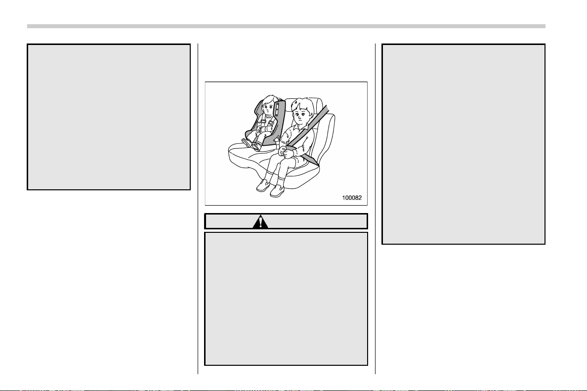
(70,1)
北米Model "A1700BE-B" EDITED: 2017/ 10/ 11
face on or near the SRS side
airbag. They could prevent prop-
er deployment of the SRS side
airbag, reducing protection avail-
able to the front seat’s occupant.
. Do not install a seat cover unless
it is a genuine SUBARU seat
cover exclusively designed for
use with the SRS airbag. Even
when using a genuine SUBARU
seat cover, the SRS side airbag
system may not function nor-
mally if the seat cover is not
installed correctly.
& General precautions regard-
ing SRS airbag system for
children
WARNING
Place children in the rear seat prop-
erly restrained at all times. The SRS
airbag deploys with considerable
speed and force and can injure or
even kill children, especially if they
are not restrained or improperly
restrained. Because children are
lighter and weaker than adults, their
risk of being injured from deploy-
ment is greater.
For that reason, we strongly recom-
mend that ALL children (including
those in child seats and those that
have outgrown child restraint de-
vices) sit in the REAR seat properly
restra ined at all times in a child
restraint device or in a seatbelt,
whichever is appropriate for t he
child’s age, height and weight.
Secure ALL types of child restraint
devices (including forward faci ng
child seats) in the REAR seats at all
times.
According to accident statistics,
children a re safer whe n properly
restrained in the rear seating posi-
tions than in the front seating posi-
tions.
For instructions and precautions
concerning the child restraint sys-
tem, refer to “Child restraint sys-
tems” F1-21.
Seat, seatbelt and SRS airbags/*SRS airbag (Supplemental Restraint System airbag)
1-38
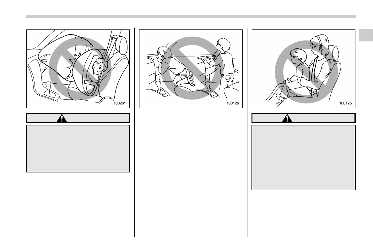
(71,1)
北米Model "A1700BE-B" EDITED: 2017/ 10/ 11
WARNING
NEVER INSTALL A FORWARD OR
REARWARD FACING CHILD SEAT IN
THE FRONT SEAT. DOING SO RISKS
SERIOUS INJURY OR DEATH TO
THE CHILD BY PLACING THE
CHILD’S HEAD TOO CLOSE TO
THE SRS AIRBAG.
WARNING
Observe the following instructions.
. Never allow a child to stand up or
kneel on the front passenger’s
seat.
. Never hold a child on your lap or
in your arms.
Since the SRS airbag deploys with
considerable force, it can injure or
even kill a child.
– CONTINUED –
Seat, seatbelt and SRS airbags/*SRS airbag (Supplemental Restraint System airbag)
1-39
1
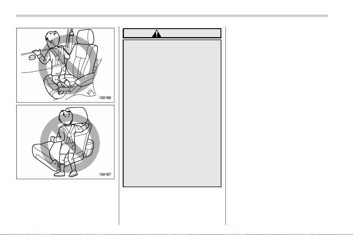
(72,1)
北米Model "A1700BE-B" EDITED: 2017/ 10/ 11
WARNING
. Never allow a child to do the
following.
– Kneel on any passenger’s seat
facing the side window
– Wrap his/her arms around the
front seat seatback
– Put his/her he ad, arms or
other parts of the body out of
the window
In the event of an accident, the
force of SRS side airbag and/or
SRS curtain airbag deployment
could injure the child seriously
because his/her head, arms or
other parts of the body are too
close to the SRS side airbag and/
or SRS curtain airbag.
. Since your vehicle is also
equipped with a front passen-
ger’s SRS frontal airbag, children
should be placed in the rear seat
anyway and should be properly
restrained at all times.
Seat, seatbelt and SRS airbags/*SRS airbag (Supplemental Restraint System airbag)
1-40
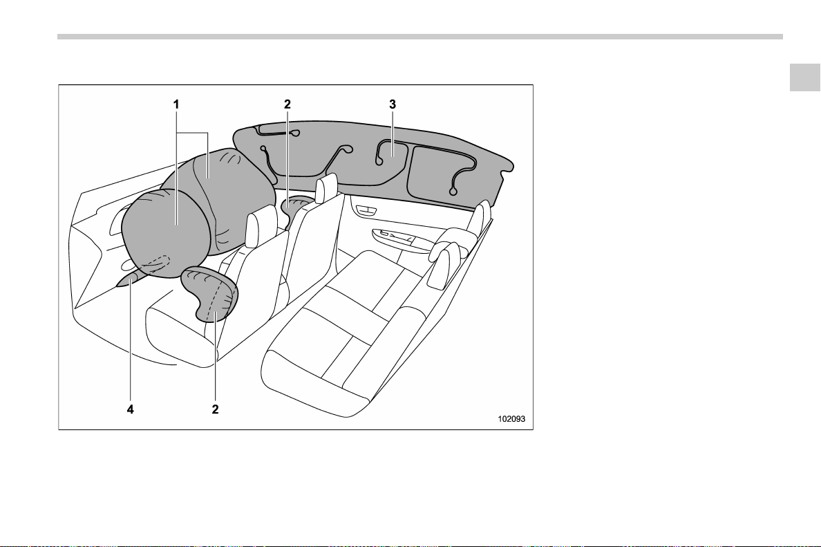
(73,1)
北米Model "A1700BE-B" EDITED: 2017/ 10/ 11
& Components
1) SRS frontal airbag
2) SRS side airbag
3) SRS curtain airbag
4) SRS knee airbag
The SRS airbags are stowed in the
following locations.
Driver’s SRS frontal airbag: in the center
portion of the steering wheel
Front passenger’s SRS frontal airbag:
near the top of the dashboard under an
“SRS AIRBAG” mark
SRS side airbag: in the door side of each
front seat seatback which bears an “SRS
AIRBAG” label
SRS curtain airbag: in the roof side
(between the front pillar and a point behind
the rear quarter glass)
An “SRS AIRBAG” mark is located at the
top of each center pillar and rear pillar.
SRS knee airbag: under th e steering
column
– CONTINUED –
Seat, seatbelt and SRS airbags/*SRS airbag (Supplemental Restraint System airbag)
1-41
1
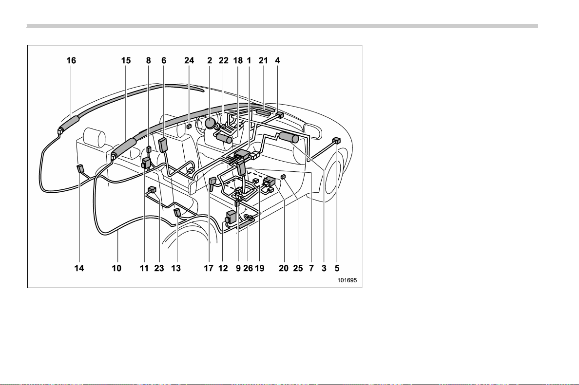
(74,1)
北米Model "A1700BE-B" EDITED: 2017/ 10/ 11
1) Airbag control module (including impact
sensor and rollover sensor)
2) Frontal airbag module (driver’s side)
3) Frontal airbag module (front passenger’s
side)
4) Front sub sensor (left-hand side)
5) Front sub sensor (right-hand side)
6) Side airbag module (driver’s side)
7) Side airbag module (front passenger’s
side)
8) Side airbag sensor (center pillar left-hand
side)
9) Side airbag sensor (center pillar right-
hand side)
10) Airbag wiring
11) Seatbelt pretensioner (driver’s side)
12) Seatbelt pretensioner (front passenger’s
side)
13) Curtain airbag sensor (rear wheel house
right-hand side)
14) Curtain airbag sensor (rear wheel house
left-hand side)
15) Curtain airbag module (right-hand side)
16) Curtain airbag module (left-hand side)
17) Seatbelt buckle switch (front passenger’s
side)
18) Knee airbag module (driver’s side)
19) Front passenger’s occupant detection
system sensor
20) Front passenger’s occupant detection
control module
21) Front passenger’s frontal airbag ON and
OFF indicator
22) SRS airbag system warning light
23) Satellite safing sensor (under the rear
center seat)
24) Front door impact sensor (left-hand side)
25) Front door impact sensor (right-han d
side)
26) Lap belt pretensioner (front passenger’s
side)
Seat, seatbelt and SRS airbags/*SRS airbag (Supplemental Restraint System airbag)
1-42
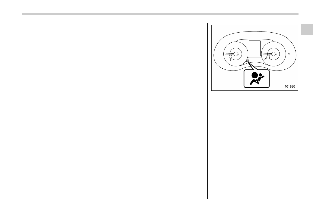
(75,1)
北米Model "A1700BE-B" EDITED: 2017/ 10/ 11
& SUBARU advanced frontal
airbag system
Your vehicle is equipped with a SUBARU
advanced frontal airbag system that com-
plies with the new advanced frontal airbag
requirements in the amended Federal
Motor Vehicle Safety Standard (FMVSS)
No. 208.
The SUBARU advanced frontal airbag
system automatically determines the de-
ployment force of the driver’s SRS frontal
airbag at the time of deployment as well as
whether or not to activate the front
passenger’s SRS frontal airbag and, if
activated, the deployment force of the SRS
frontal airbag at the time of deployment.
Your vehicle has warning labels on the
driver’s and front passenger’s sun visors
beginning with the phrase “EVEN WITH
ADVANCED AIR BAGS” and a tag at-
tached to the glove box lid beginning with
the phrase “Even with Advanced Air
Bags”. Make sure that you carefully read
the instructions on the warning labels and
tag.
Always wear your seatbelt. The SUBARU
advanced frontal airbag system is a
supplemental restraint system and must
be used in combination with a seatbelt. All
occupants should wear a seatbelt or be
seated in an appropriate child restraint
system.
For the locations of the SRS airbags, refer
to “Components” F1-41.
In a moderate to severe frontal collision,
the following components deploy.
. SRS frontal airbag for driver
. SRS frontal airbag for front passenger
. SRS knee airbag for driver
. SRS curtain airbag
*1
*1: When an offset frontal collision that is severe
enough to deploy the front airbag occurs.
These components supplement the seat-
belts by reducing the impact to the
occupant’s head, chest and knees.
! Driver’s SRS frontal airbag
The driver’s SRS frontal airbag uses a dual
stage inflator. The inflator op erates in
different ways depending on the severity
of impact.
SRS airbag system warning light
Have the system inspected by your
SUBARU dealer immediately if the SRS
airbag system warning light illuminates.
NOTE
The driver’s SRS side airbag and SRS
curtain airbag are not controlled by the
SUBARU advanced frontal airbag sys-
tem.
! Front passenger’s SRS frontal air-
bag
The front passenger’s SRS frontal airbag
uses a dual stage inflator. The inflator
operates in different ways depending on
the severity of impact.
The occupant detection system sensor is
installed under the seat upholstery and
– CONTINUED –
Seat, seatbelt and SRS airbags/*SRS airbag (Supplemental Restraint System airbag)
1-43
1
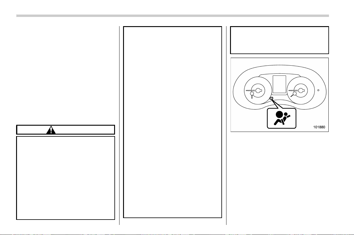
(76,1)
北米Model "A1700BE-B" EDITED: 2017/ 10/ 11
monitors the physique and posture of the
front passenger. Using this information,
the occupant detection system determines
whether the front passenger’s SRS frontal
airbag should be deployed or not.
The occupant detection system may not
inflate the front passenger’s SRS frontal
airbag even when the driver’s SRS frontal
airbag deploys. This is normal. In this
case, although the front passenger’s SRS
frontal airbag does not operate, the front
passenger’s seatbelt pretensioner oper-
ates with the driver’s seatbelt preten-
sioner. For details about the seatbelt
pretensioner, refer to “Front seatbelt pre-
tensioners” F1-17.
CAUTION
Observe the following precautions.
Failure to do so may prevent the
SUBARU advanced frontal airbag
system from functioning correctly
or cause the system to fail.
. Do not apply any strong impact to
the front passenger’s seat such
as by kicking.
. Do not let rear passengers rest
their feet between the front seat-
back and seat cushion.
. Do not spill liquid on the front
passenger ’s seat. If liqui d is
spilled, wipe it off immediately.
. Do not remove or disassemble
the front passenger’s seat.
. Do not install any accessory
(such as an audio amplifier) other
than a genuine SUBARU acces-
sory under the front passenger’s
seat.
. Do not place anything (s hoes,
umbrella, etc.) under the front
passenger’s seat.
. Do not use the front passenger’s
seat with the head restraint re-
moved.
. Do not leave any articles on the
front passenger’s seat or the
seatbelt tongue and buckle en-
gaged when you leave your vehi-
cle.
. Do not put sharp object(s) on the
seat or pierce the seat uphols-
tery.
. Do not place a magnet near the
seatbelt buckle and the seatbelt
retractor.
. Do not use front seats with their
backward-forward position and
seatback not being locked into
place securely. If any of them are
not locked securely, adjust them
again. For adjusting procedure,
refer to “Manual seat” F 1-4
(models equipped with manual
seats only).
SRS airbag system warning light
If the seatbelt buckle switch and/or front
passenger’s occupant detection system
have failed, the SRS airbag system warn-
ing light will illuminate. Have the system
inspected by your SUBARU dealer imme-
diately if the SRS airbag system warning
light illuminates.
If your vehicle has sustained impact, this
may affect the proper function of the
SUBARU advanced frontal airbag system.
Have your vehicle inspected at your
SUBARU dealer. Do not let anyone use
the front passenger’s seat while you are
Seat, seatbelt and SRS airbags/*SRS airbag (Supplemental Restraint System airbag)
1-44
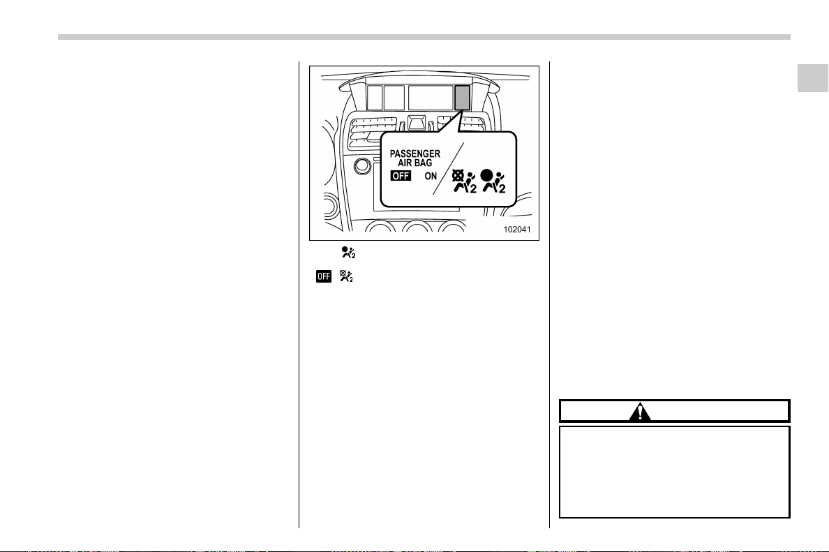
(77,1)
北米Model "A1700BE-B" EDITED: 2017/ 10/ 11
driving the vehicle to your SUBARU deal-
er.
NOTE
The front passenger’s SRS side airbag
and SRS curtain airbag are not con-
trolled by the SUBARU advanced fron-
tal airbag system.
! Passenger’s frontal airbag ON and
OFF indicators
Refer to “Front passenger’s frontal airbag
ON and OFF indicators” F3-16.
! Occupant detection system
The occupant detection system sensor is
installed under the seat upholstery and
monitors the physique and posture of the
front passenger. Using this information,
the occupant detection system determines
whether the front passenger’s SRS frontal
airbag should be deployed or not.
ON / : Front passenger’s frontal airbag ON
indicator
/ : Front passenger’s frontal airbag OFF
indicator
If the front passenger’s seat cushion is
wet, this may adversely affect the ability of
the system to determine deployment. If the
seat cushion is wet, the front passenger
should stop sitting on the front passen-
ger ’s seat. Wipe off liquid from the seat
immediately, let the seat dry naturally and
then check the SRS airbag system warn-
ing light as follows.
. If the SRS airbag system warning light
illuminates, keep the seat dry until the
warning light turns off. If the SRS airbag
system warning light stays on even when
the seat has dried, do not allow anyone to
sit on the front passenger’s seat and have
the system checked by your SUBARU
dealer.
. If the SRS airbag system warning light
does not illuminate, check that the front
passenger’s frontal airbag ON and OFF
indicators work properly. If the indicators
do not work properly, do not allow anyone
to sit on the front passenger’s seat and
have the system checked by your
SUBARU dealer.
Also, if luggage or electronic devices are
placed on the front passenger’s seat, this
may adversely affect the ability of the
system to determine deployment. This
may prevent the front passenger’s frontal
airbag ON and OFF indicators from work-
ing properly. Check that the indicators
work properly.
When the OFF indicator turns off and the
ON indicator illuminates, the front passen-
ger’s frontal airbag may deploy during a
collision. Remove luggage and electronic
devices from the front passenger’s seat.
CAUTION
Electronic devices
*
may affect the
occupant detection system, espe-
cially under either of the following
conditions.
. when placed on the front passen-
ger’s seat while connected to the
– CONTINUED –
Seat, seatbelt and SRS airbags/*SRS airbag (Supplemental Restraint System airbag)
1-45
1
(78,1)
北米Model "A1700BE-B" EDITED: 2017/ 10/ 11
accessory power outlet
. when used by the front passen-
ger
*Example: cell phones, laptops, por-
table music players, or electronic
games
If either of the following situations
occurs when using an electronic
device in the vehicle, at first try to
relocate that device to avoid it
creating any interference.
. The SRS airbag system warning
light illuminates.
. The front passenger’s frontal air-
bag ON and OFF indicators oper-
ate erratically.
If the i nterference remains, stop
using the device in the vehicle.
NOTE
This device complies with Part 18 of the
FCC Rules. This device may cause
interference. If this device causes inter-
ference, consult the nearest SUBARU
dealer. Also, for maintenance of the
system, consult the nearest SUBARU
dealer. This product may cause inter-
ference to radio equipment and should
not be installed near maritime safety
communications equipment or other
critical navigation or communication
equipment operating between 0.45-30
MHz.
! Conditions in which front passen-
ger’s SRS frontal airbag is not
activated
The front passenger’s SRS frontal airbag
will not be activated when any of the
following conditions are met regarding
the front passenger’s seat:
. The seat is empty.
. The seat is equipped with an appro-
priate child restraint system and an infant
is restrained in it. (See WARNING that
follows.)
. The front passenger’s occupant detec-
tion system is malfunctioning.
WARNING
NEVER INSTALL A FORWARD OR
REARWARD FACING CHILD SEAT IN
THE FRONT PASSENGER’S SEAT
EVEN IF THE FRONT PASSENGER’S
SRS FRONTAL AIRBAG IS DEACTI-
VATED. Be sure to install it in the
REAR seat in a correct manner. Also,
it is strongly recommended that any
forward facing child seat or booster
seat be installed in the REAR seat,
and that even children who have
outgrown a child restraint system be
also seated in the REAR seat. This is
because children sitting in the front
passenger’s seat may be killed or
severely injured should the front
passenger’s SRS frontal airbag de-
ploy. REAR s eats are the safest
place for children.
CAUTION
When the front passenger’s seat is
occupied by an infant in an appro-
priate child restraint system, ob-
serve the following precautions.
Failure to do so may interfere with
the proper operation of the occupant
detection system, activating the
front passenger’s SRS frontal airbag
even though that seat is occupied by
the infant in the child restraint
system.
. Do not place any article (includ-
ing electronic devices) on the
seat other than the infant in the
child restraint system.
Seat, seatbelt and SRS airbags/*SRS airbag (Supplemental Restraint System airbag)
1-46
(79,1)
北米Model "A1700BE-B" EDITED: 2017/ 10/ 11
. Do not place more than one infant
in the child restraint system.
! If the front passenger’s frontal
airbag ON indicator illuminates
and the OFF indicator turns off
even when an infant or a small
child is in a child restraint sys-
tem (including booster seat)
1. Turn the ignition switch to the “LOCK”/
“OFF” position.
2. Remove the child restraint system from
the seat.
3. By referring to the child restraint
manufacturer’s recommendations as well
as the child restraint system installation
procedures in “Child restraint systems”
F1-21, correctly install the child restraint
system.
4. Turn the ignition switch to the “ON”
position and make sure that the front
passenger’s frontal airbag ON indicator
turns off and the OFF indicator illuminates.
If still the ON indicator remains illuminated
while the OFF indicator turns off, take the
following actions.
. Ensure that no article is placed on the
seat other than the child restraint system
and the child occupant.
. Ensure that the backward-forward po-
sition and seatback of front passenger’s
seat are locked into place securely by
moving the seat back and forth.
If the ON indicator still remains illuminated
while the OFF indicator turns off after
taking releva nt correct ive action s de-
scribed above, relocate the child restraint
system to the rear seat and immediately
contact your SUBARU dealer for an
inspection.
NOTE
When a child who has outgrown a child
restraint system or a small adult is
seated in the front passenger’s seat,
the SUBARU advanced frontal airbag
system may or may not activate the
front passenger’s SRS frontal airbag
depending on the occupant’s seating
posture. Children should always wear a
seatbelt when sitting in the seat irre-
spective of whether the airbag is deac-
tivated or activated. If the front passen-
ger’s SRS frontal airbag is activated
(the ON indicator remains illuminated
while the OFF indicator turns off),
ensure that no article is placed on the
seat other than the occupant.
If the ON indicator still remains illumi-
nated while the OFF indicator turns off
despite the fact that the actions noted
above have been taken, seat the child/
small adult in the rear seat and imme-
diately contact your SUBARU dealer for
an inspection. Even if the system has
passed the dealer inspection, it is
recommended that on subsequent trips
the child/small adult always take the
rear seat.
Children who have outgrown a child
restraint system should always wear the
seatbelt irrespective of whether the airbag
is deactivated or activated.
! Conditions in which front passen-
ger’s SRS frontal airbag is activated
The front passenger’s SRS frontal airbag
will be activ ated for deployment upon
impact when any of the following condi-
tions are met regarding the front passen-
ger’s seat.
. When the seat is occupied by an adult.
. When certain items (e.g. jug of water)
are placed on the seat.
– CONTINUED –
Seat, seatbelt and SRS airbags/*SRS airbag (Supplemental Restraint System airbag)
1-47
1

(80,1)
北米Model "A1700BE-B" EDITED: 2017/ 10/ 11
! If the passenger’s frontal airbag
OFF indicator illuminates and the
ON indicator turns off even when
the front passenger’s seat is
occupied by an adult
This can be caused by the adult incorrectly
sitting in the front passenger’s seat.
1. Turn the ignition switch to the “LOCK”/
“OFF” position.
2. Ask the front passenger to set the
seatback to the upright position, sit up
straight in the center of the seat cushion,
correctly fasten the seatbelt, position his/
her legs out forward, and adjust the seat to
the rearmost position.
3. Turn the ignition switch to the “ON”
position.
If the OFF indicator remains illuminated
while the ON indicator remains off, take the
following actions.
1. Turn the ignition switch to the “LOCK”/
“OFF” position.
2. Make sure that the front passenger
does not use a blanket, seat cushion, seat
cover, seat heater or massager, etc.
3. If wearing excessive layers of clothing,
the front passenger should remove any
unnecessary items before sitting in the
front passenger’s seat, or should sit in a
rear seat.
4. Turn the ignition switch to the “ON”
position and wait 6 seconds to allow the
system to complete self-checking. Follow-
ing the system check, both indicators turn
off for 2 seconds. Now, the ON indicator
should illuminate while the OFF indicator
remains off.
If the OFF indicator still remains illumi-
nated while the ON indicator remains off,
ask the occupant to move to the rear seat
and immediately contact your SUBARU
dealer for an inspection.
Seat, seatbelt and SRS airbags/*SRS airbag (Supplemental Restraint System airbag)
1-48
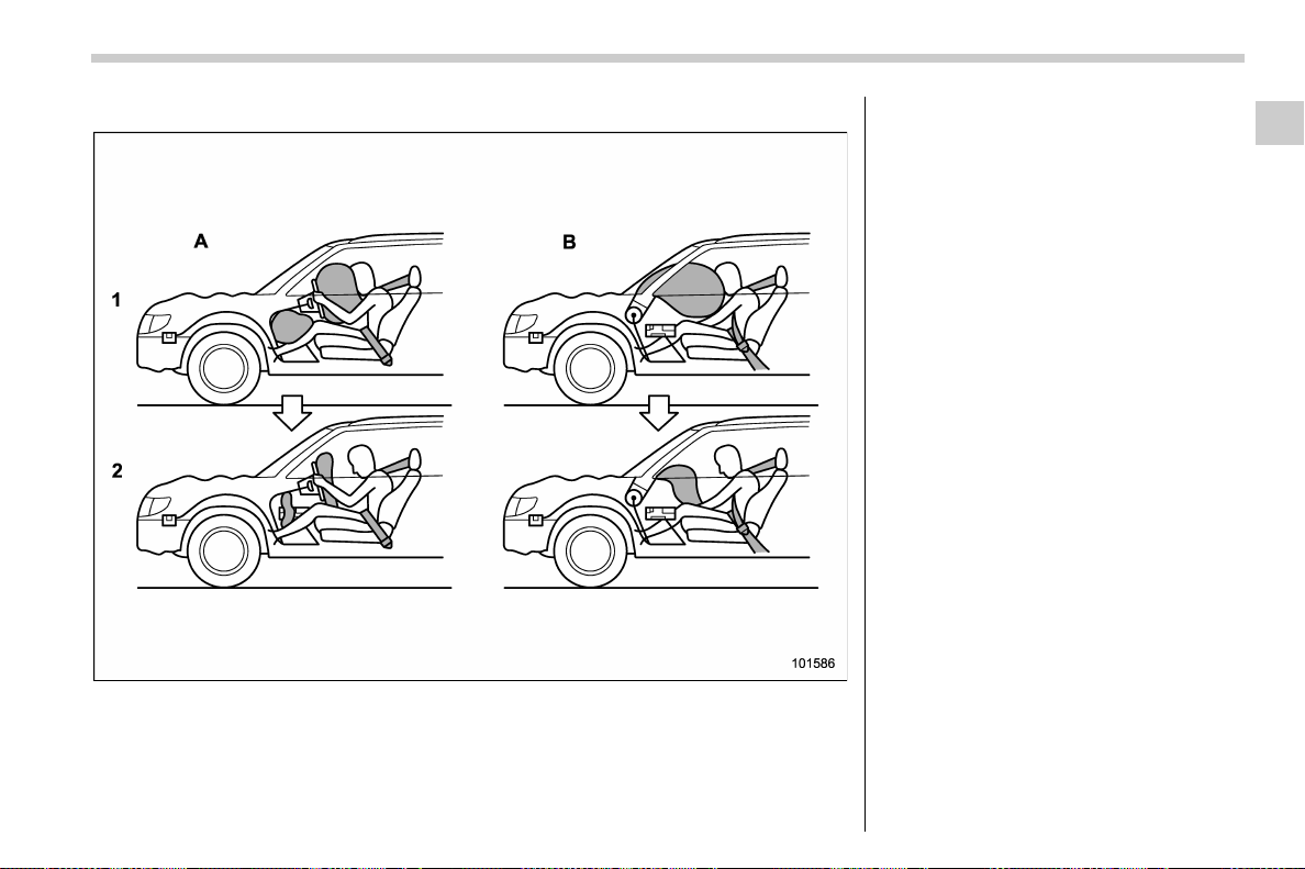
(81,1)
北米Model "A1700BE-B" EDITED: 2017/ 10/ 11
! Operation
A) Driver’s side
B) Passenger’s side
1) SRS AIRBAGs deploy as soon as a collision occurs.
2) After deployment, SRS AIRBAGs start to deflate immediately so that the driver’s vision is not
obstructed.
The SRS airbags can function only when
the ignition switch is in the “ON” position.
The SUBARU advanced frontal airbag
system is designed to determine the
activation or deactivation condition of the
front passenger’s SRS frontal airbag de-
pending on the characteristic of item(s) or
person on the front p assenger’s seat
monitored by the front passenger’s occu-
pant detection system sensor. For this
reason, only the driver ’ s S RS frontal
airbag may deploy in the event of a
collision, but this does not mean failure of
the system.
If the following sensors detect a predeter-
mined amount of force during a frontal
collision, the control module sends signals
to the a irbag module(s) (only driver’s
module or both driver’s and front passen-
ger’s modules) instructing the module(s) to
inflate the SRS frontal airbag(s).
. the front sub sensors
. the impact sensors in the airbag control
module
On the driver’s side, the SRS knee airbag
also inflates with the SRS frontal airbag.
– CONTINUED –
Seat, seatbelt and SRS airbags/*SRS airbag (Supplemental Restraint System airbag)
1-49
1
(82,1)
北米Model "A1700BE-B" EDITED: 2017/ 10/ 11
The driver’s and front passenger’s SRS
frontal airbags use dual stage inflators.
The two inflators of each airbag are
triggered either sequentially or simulta-
neously, depending on the severity of
impact, in the case of the driver’s SRS
frontal airbag and depending on the
severity of impact and the characteristic
of item(s) or person on the seat in the case
of the front passenger’s SRS frontal air-
bag.
! After deployment
After deployment, the SRS airbag imme-
diately starts to deflate so that the driver’s
vision is not obstructed and the driver’s
ability to maintain control of the vehicle is
not impaired. The time required from
detecting impact to the deflation of the
SRS airbag after deployment is shorter
than the blink of an eye.
Both when only the driver’s SRS frontal
airbag deploys and the driver’s and front
passenger’s SRS frontal airbags deploy,
the driver’s and front passenger’s seatbelt
pretensioners operate at the same time.
Although it is highly unlikely that the SRS
airbag would activate in a non-accident
situation, should it occur, the SRS airbag
will deflate quickly, not obscuring vision
and will not interfere with the driver’s ability
to maintain control of the vehicle.
When the SRS airbag deploys, a sudden,
fairly loud inflation noise will be heard and
some smoke will be released. These
occurrences are a normal result of the
deployment. This smoke does not indicate
a fire in the vehicle.
CAUTION
Do not touch the SRS airbag system
components around the steering
wheel and dashboard with b are
hands right after deployment. Doing
so can cause burns because the
components can be very hot as a
result of deployment.
! Example of the type of accident
The driver’s SRS frontal airbag and front
passenger’s SRS frontal airbag are de-
signed as follows.
. to deploy in the event of an accident
involving a moderate to severe frontal
collision
. to function on a one-time-only basis
The driver’s SRS frontal airbag and front
passenger’s SRS frontal airbag are not
designed as follows.
. to deploy in most lesser frontal im-
pacts
*1
. to deploy in most side or rear impacts or
in most rollover accidents
*2
*1: Because the necessary protection can be
achieved by the seatbelt alone.
*2: Because deployment of only the driver’s
SRS frontal airbag or both the driver’s and front
passenge r’s SRS frontal airbags would no t
protect the occupant in those situations.
SRS airbag deployment depends on the
level of force experienced in the passen-
ger compartment during a collision. That
level differs from one type of collision to
another, and it may have no bearing on the
visible damage done to the vehicle itself.
Seat, seatbelt and SRS airbags/*SRS airbag (Supplemental Restraint System airbag)
1-50
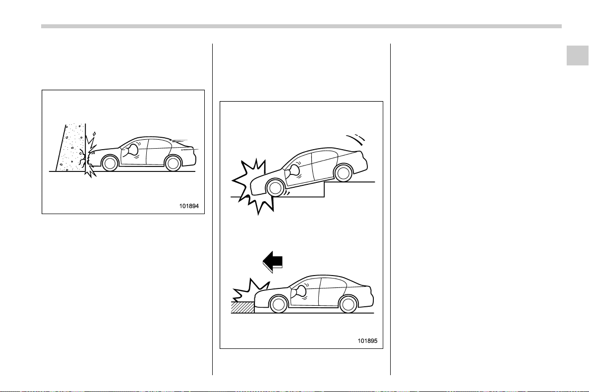
(83,1)
北米Model "A1700BE-B" EDITED: 2017/ 10/ 11
! Example of accident in which the
driver’s/driver’s and front pas-
senger’s SRS frontal airbag(s)
will most likely deploy
A head-on collision against a thick con-
crete wall at a vehicle speed of 12 to 19
mph (20 to 30 km/h) or higher activates
only the driver’s SRS frontal airbag or both
driver’s and front passenger’s SRS frontal
airbags. The airbag(s) will also be acti-
vated when the vehicle is exposed to a
frontal impact similar in fashion and
magnitude to the coll ision describe d
above.
! Examples of the types of acci-
dents in which it is possible that
the driver’s/driver’s and front
passenger’s SRS frontal
airbag(s) will deploy
Only the driver’s SRS frontal airbag or both
driver’s and front passenger’s SRS frontal
airbags may be activated when the vehicle
sustains a hard impact in the undercar-
riage area from the road surface (such as
when the vehicle plunges into a deep ditch,
is severely impacted or knocked hard
against an obstacle on the road such as
a curb).
– CONTINUED –
Seat, seatbelt and SRS airbags/*SRS airbag (Supplemental Restraint System airbag)
1-51
1
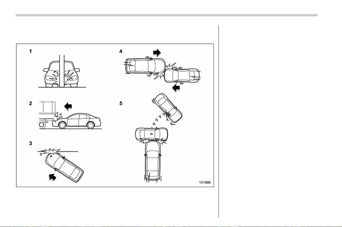
(84,1)
北米Model "A1700BE-B" EDITED: 2017/ 10/ 11
! Examples of the types of accidents in which deployment of the driver’s/
driver’s and front passenger’s SRS frontal airbag(s) is unlikely to occur
1) The vehicle strikes an object, such as a
telephone pole or sign pole.
2) The vehicle slides under the load bed of a
truck.
3) The vehicle sustains an oblique offset
frontal impact.
4) The vehicle sustains an offset frontal
collision.
5) The vehicle strikes an object that can
move or deform, such as a parked
vehicle.
There are many types of collisions which
might not necessarily require deployment
of driver’s/driver’s and front passenger’s
SRS frontal airbag(s). In the event of
accidents like those illustrated, the dri-
ver’s/driver’s and front passenger’s SRS
frontal airbag(s) may not deploy depend-
ing on the level of accident forces involved.
Seat, seatbelt and SRS airbags/*SRS airbag (Supplemental Restraint System airbag)
1-52
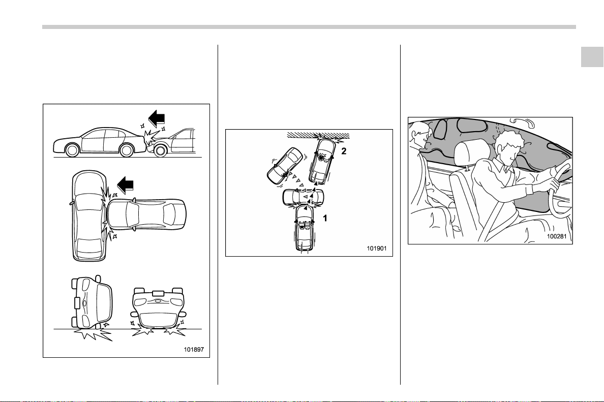
(85,1)
北米Model "A1700BE-B" EDITED: 2017/ 10/ 11
! Examples of the types of acci-
dents in which the driver’s/dri-
ver’s and front passenger’s SRS
frontal airbag(s) are not de-
signed to deploy in most cases
The driver’s and front passenger’s SRS
frontal airbags are not designed to deploy
in most of the following cases.
. If the vehicle is struck from the side or
from behind
. If the vehicle rolls onto its side or roof
. If the vehicle is involved in a low-speed
frontal collision
1) First impact
2) Second impact
In an acci dent where the vehicle is
impacted more than once, the driver’s
and/or front passenger’s SRS frontal
airbag(s) will deploy only once on the first
impact.
Example: In the case of a double collision,
first with another vehicle, then against a
concrete wall in immediate succession,
once either or both of the driver’s and front
passenger’s SRS frontal airbags is/are
activated on the first impact, it/they will
not be activated on the second impact.
& SRS side airbag and SRS
curtain airbag
! SRS side airbag
The SRS side airbag is stored in the door
side of each front seat seatback, which
bears an “SRS AIRBAG” label.
Inamoderatetoseveresideimpact
collision, the SRS side airbag on the
impacted side of the vehicle deploys
between the occupant and the door panel
and supplements the seatbelt by reducing
the impact on the occupant’s chest and
waist. The SRS side airbag operates only
for front seat occupants.
– CONTINUED –
Seat, seatbelt and SRS airbags/*SRS airbag (Supplemental Restraint System airbag)
1-53
1

(86,1)
北米Model "A1700BE-B" EDITED: 2017/ 10/ 11
! SRS curtain airbag
Your vehicle is equipped with a SUBARU
SRS curtain airbag system that complies
with the Federal Motor Vehicle Safety
Standard (FMVSS) No. 226.
The SRS curtain airbag on each side of the
cabin is stored in the roof side (between
the front pillar and a point over the rear
seat). An “SRS AIRBAG” mark is located
at the top of each center pillar.
Inamoderatetoseveresideimpact
collision, the SRS curtain airbag on the
impacted side of the vehicle deploys
between the occupant and the side win-
dow and supplements the seatbelt by
reducing the impact on the occupant’s
head.
In a rollover, SRS curtain airbags on both
sides of the vehicle deploy between the
occupant and the side window and supple-
ment the seatbelt by reducing the impact to
the occupant’s head.
In an offset frontal collision, SRS curtain
airbags on both sides of the vehicle deploy
between the occupant and the side win-
dow and supplement the seatbelt by
reducing the impact to the occupant’s
head.
! Operation
The SRS side airbag and SRS curtain
airbag can function only when the ignition
switch is in the “ON” position.
The following airbags deploy indepen-
dently of each other since each has its
own impact sensor.
. Driver’s SRS side airbag
. Front passenger’s SRS side airbag
. SRS curtain airbag (right-hand side)
. SRS curtain airbag (left-hand side)
Therefore, they may not both deploy in the
same accident. Also, the SRS side airbag
and SRS curtain airbag deploys indepen-
dently of the driver’s and front passenger’s
SRS frontal airbags in the steering wheel
and instrument panel.
An impact sensor, which senses impact
force, is located in each of the following
locations.
. In the left and right front doors
. In the left and right center pillars
. In the left and right rear wheel houses
. Under the rear center seat
. On both sides of the radiator panel
(frontal impact sensor)
The rollover sensor and frontal impact
sensor are located inside the airbag
control module, which is located under
the center of the instrument panel.
Seat, seatbelt and SRS airbags/*SRS airbag (Supplemental Restraint System airbag)
1-54

(87,1)
北米Model "A1700BE-B" EDITED: 2017/ 10/ 11
! In cases of rollover accident or side collisions, the following components will operate simultaneously
Impact sensors affected
SRS side airbags SRS curtain airbags
Seatbelt pretensioner
(shoulder belt pretensioner only)
Impacted side
Non-impacted
side
Impacted side
Non-impacted
side
Impacted side
Non-impacted
side
Both of the sen-
sors together
sense an impact
force
Impact sensor in
front doors
* – * – * –
Impact sensor
under rear cen-
ter seat
Both of the sen-
sors together
sense an impact
force
Impact sensor in
center pillars
* – * –––
Impact sensor
under rear cen-
ter seat
Both of the sen-
sors together
sense an impact
force
Impact sensor in
rear wheel
houses
––* –––
Impact sensor
under rear cen-
ter seat
Rollover sensor in airbag control
module
––***
*
*: Activated
–: Not activated
NOTE
The SRS side airbag and SRS curtain airbag deploy even when no one occupies the seat on the side on which an impact is
applied.
– CONTINUED –
Seat, seatbelt and SRS airbags/*SRS airbag (Supplemental Restraint System airbag)
1-55
1
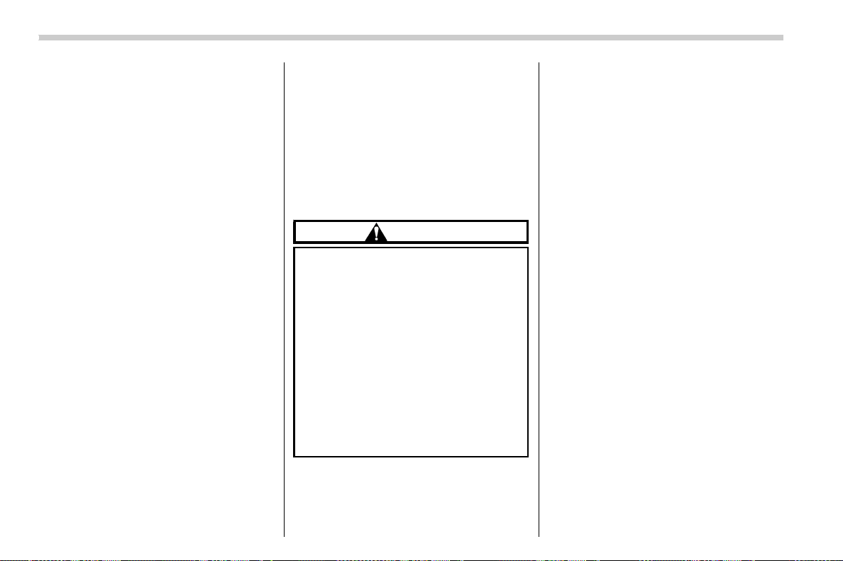
(88,1)
北米Model "A1700BE-B" EDITED: 2017/ 10/ 11
! In case of frontal collision
The SRS curtain airbags are designed to
deploy in the following cases.
. When the driver’s SRS frontal airbag
deploys in a frontal collision
. When the driver’s and front passen-
ger’s SRS frontal airbags de ploy in a
frontal collision
. When the system determines that the
collision is an offset frontal collision
The SRS curtain airbags are basically
designed not to deploy in the following
cases.
. When the SRS frontal airbags do not
deploy
. When the system determines that the
collision is other than an offset frontal
collision
! After deployment
After the deployment, the SRS side airbag
immediately starts to deflate. The time
required from detection of an impact to
deflation of an SRS side airbag after
deployment is shorter than the blink of an
eye.
The SRS curtain airbag remains inflated
for a while following deplo yment then
slowly deflates.
The SRS side airbag and SRS curtain
airbag deploy even when no one occupies
the seat on the side on which an impact is
applied.
When the SRS side airbag and SRS
curtain airbag deploy, a sudden, fairly loud
inflation noise will be heard and some
smoke w ill be released. These occur-
rences are a normal result of the deploy-
ment. This smoke does not indicate a fire
in the vehicle.
CAUTION
Do not touch the SRS side airbag
system components aro und the
front seat seatback with bare hands
right after deployment. Doing so can
cause burns because the compo-
nents can be very hot as a result of
deployment.
After deployment, do not touch any
part of the SRS curtain airbag sys-
tem (from the front pillar to the part
of the roof side over the rear seat).
Doing so can cause burns because
the components can be very hot as a
result of deployment.
! Example of the type of accident
The SRS side airbag and SRS curtain
airbag are designed as follows:
. to deploy in the event of an accident
involving a moderate to severe side impact
collision
. to function on a one-time-only basis.
The SRS side airbag and SRS curtain
airbag are not designed to deploy in the
following cases:
. in most lesser side impact
. in most frontal or most rear impacts
(because the SRS side airbag and SRS
curtain airbag deployment would not pro-
tect the occupant in those situations.)
The SRS curtain airbags are also de-
signed to deploy when the vehicle is in an
extremely inclined state such as during a
rollover. They are not designed to deploy in
most lesser inclined state.
The SRS side airbag and SRS curtain
airbag deployment depend on the level of
force experienced in the passenger com-
partment during a side impact collision.
That level differs from one type of collision
to another, and it may have no bearing on
the visible damage done to the vehicle
itself.
Seat, seatbelt and SRS airbags/*SRS airbag (Supplemental Restraint System airbag)
1-56
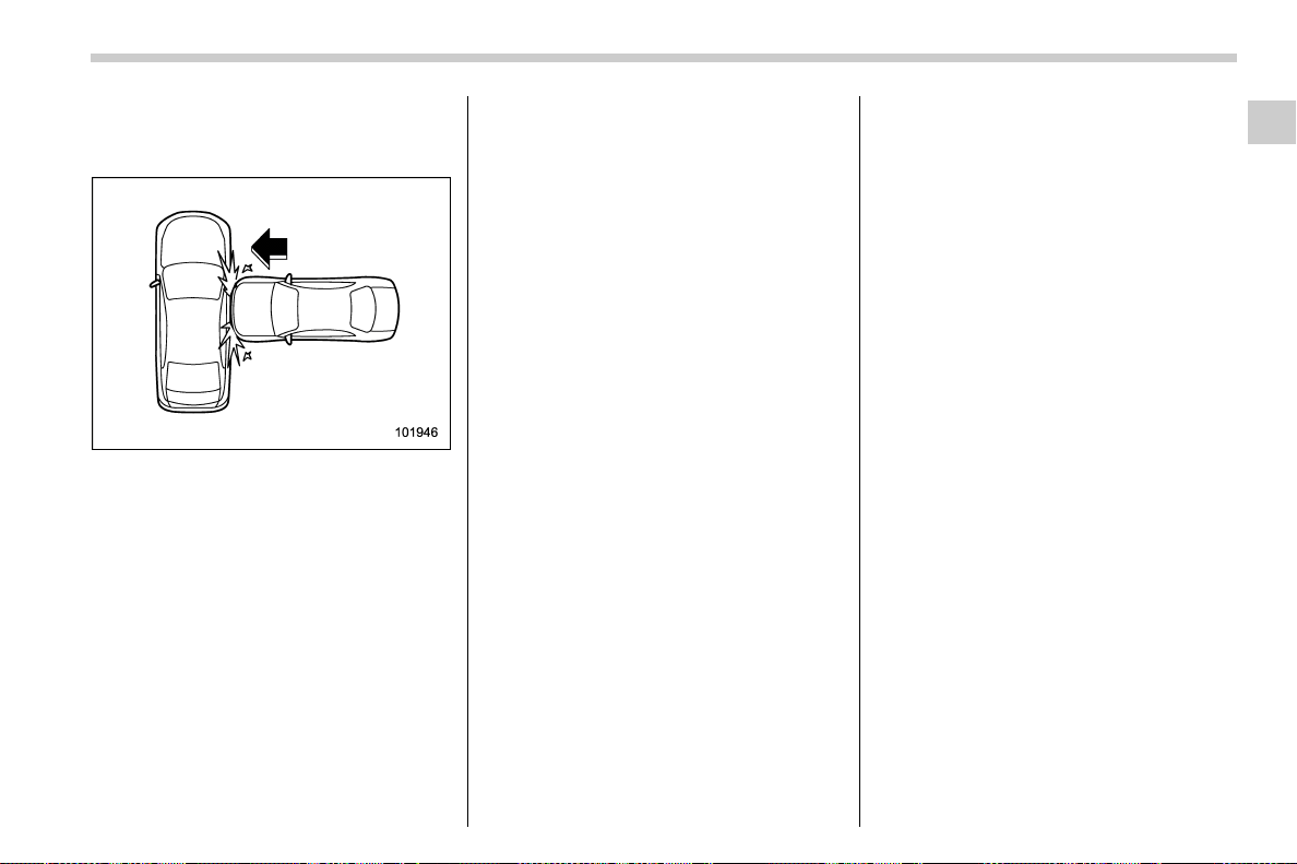
(89,1)
北米Model "A1700BE-B" EDITED: 2017/ 10/ 11
! Example of the type of accident in
which the SRS side airbag will
most likely deploy.
A severe side impact near the front seat.
– CONTINUED –
Seat, seatbelt and SRS airbags/*SRS airbag (Supplemental Restraint System airbag)
1-57
1
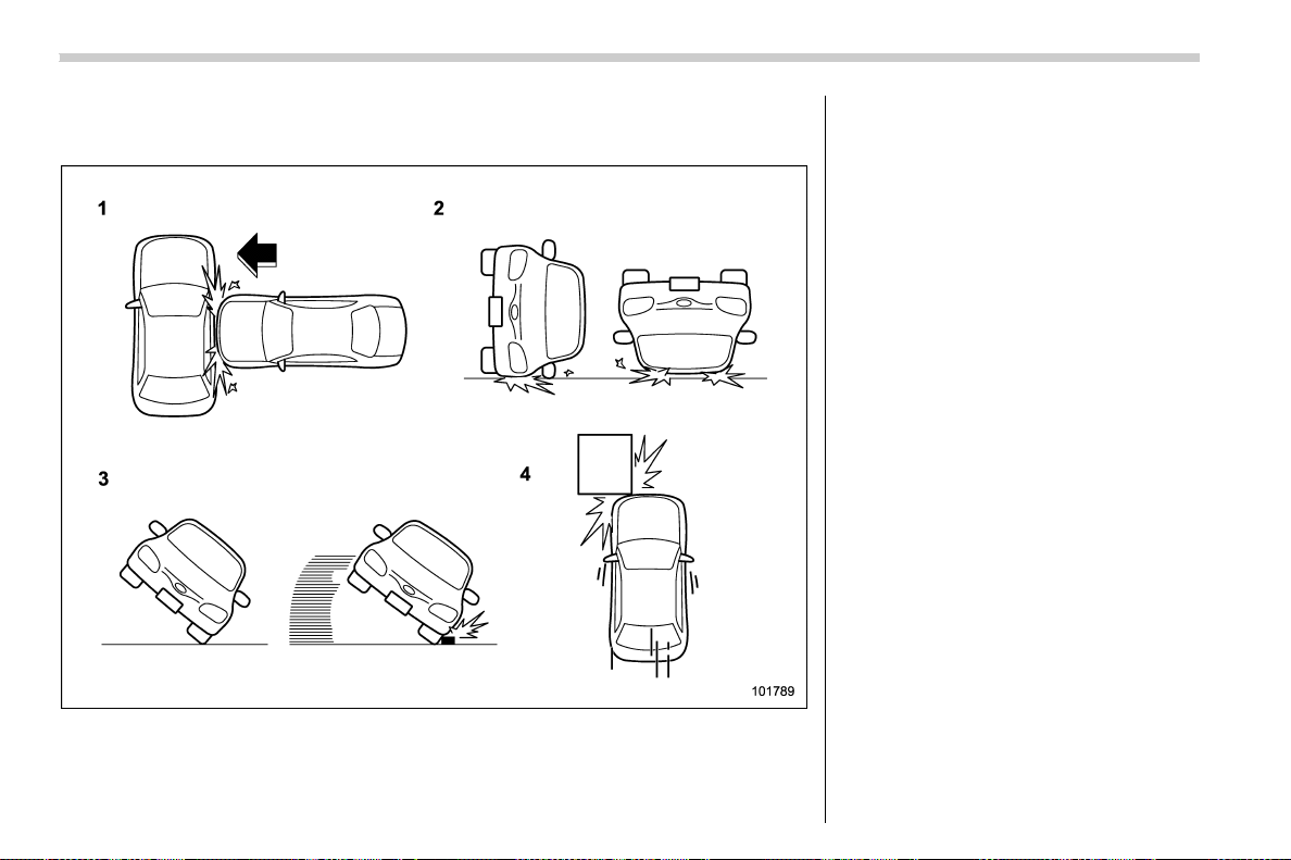
(90,1)
北米Model "A1700BE-B" EDITED: 2017/ 10/ 11
! Examples of the types of accidents in which the SRS curtain airbag will most
likely deploy.
1) The vehicle is involved in a severe side
impact near the front seat or the rear seat.
2) The vehicle rolls onto its side or the roof.
3) The angle of vehicle tip-up is marginal or
the skidding vehicle’s tires hit a curbstone
laterally.
4) An offset frontal collision that is severe
enough to deploy the front airbag.
Seat, seatbelt and SRS airbags/*SRS airbag (Supplemental Restraint System airbag)
1-58
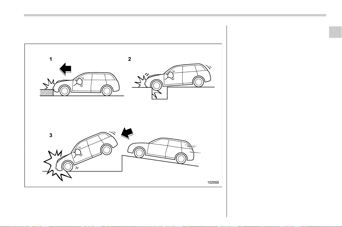
(91,1)
北米Model "A1700BE-B" EDITED: 2017/ 10/ 11
! Examples of the types of accidents in which it is possible that the SRS side
airbag and the SRS curtain airbag will deploy.
1) Hitting a curb, edge of pavement or hard
surface
2) Falling into or jumping over a deep hole
3) Landing hard or vehicle falling
It is possible that the SRS side and curtain
airbags will deploy if a serious impact
occurs to the underside of your vehicle.
Some examples are shown in the illustra-
tion.
– CONTINUED –
Seat, seatbelt and SRS airbags/*SRS airbag (Supplemental Restraint System airbag)
1-59
1
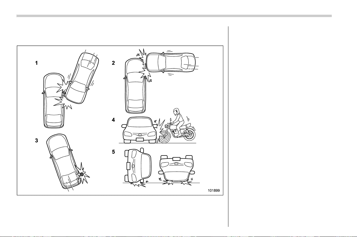
(92,1)
北米Model "A1700BE-B" EDITED: 2017/ 10/ 11
! Examples of the types of accidents in which the SRS side airbag is unlikely to
deploy.
1) The vehicle is involved in an oblique side-
on impact.
2) The vehicle is involved in a side-on
impact in an area outside the vicinity of
the passenger compartment.
3) The vehicle strikes a telephone pole or
similar object.
4) The vehicle is involved in a side-on
impact from a motorcycle.
5) The vehicle rolls onto its side or the roof.
There are many types of collisions which
might not necessarily require the SRS side
airbag deployment. In the event of acci-
dents like those illustrated, the SRS side
airbag may not deploy depending on the
level of accident forces involved.
Seat, seatbelt and SRS airbags/*SRS airbag (Supplemental Restraint System airbag)
1-60
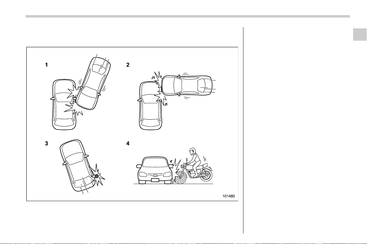
(93,1)
北米Model "A1700BE-B" EDITED: 2017/ 10/ 11
! Examples of the types of accidents in which the SRS curtain airbag is unlikely
to deploy.
1) The vehicle is involved in an oblique side-
on impact.
2) The vehicle is involved in a side-on
impact in an area outside the vicinity of
the passenger compartment.
3) The vehicle strikes a telephone pole or
similar object.
4) The vehicle is involved in a side-on
impact from a motorcycle.
There are many types of collisions which
might not necessarily require SRS curtain
airbag deployment. In the event of acci-
dents like those illustrated, the SRS
curtain airbag may not deploy depending
on the level of accident forces involved.
– CONTINUED –
Seat, seatbelt and SRS airbags/*SRS airbag (Supplemental Restraint System airbag)
1-61
1
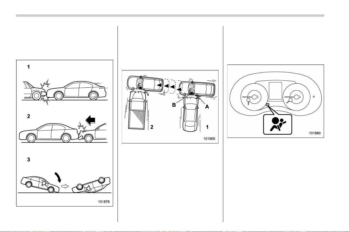
(94,1)
北米Model "A1700BE-B" EDITED: 2017/ 10/ 11
! Examples of the types of acci-
dents in which the SRS side
airbag and SRS curtain airbag
are not designed to deploy in
most cases
1) The vehicle is involved in frontal collision
with another vehicle (moving or station-
ary).
2) The vehicle is struck from behind.
3) The vehicle pitches end over end.
In the event of accidents like those
illustrated, the SRS side airbag and SRS
curtain airbag are not designed to deploy
in most cases.
1) First impact
2) Second impact
A) SRS curtain airbag
B) SRS side airbag
In an accident where the vehicle is struck
from the side more than once, the SRS
side airbag and SRS curtain airbag deploy
only once on the first impact.
Example: In the case of a double side
impact collision, first with one vehicle and
immediately followed by another from the
same direction, once the SRS side airbag
and SRS curtain airbag are activated on
the first impact, they will not be activated
on the second.
& SRS airbag system monitors
SRS airbag system warning light
A diagnostic system continually monitors
the readiness of the SRS airbag system
(including front seatbelt pretensioners)
while the vehicle is being driven. The
SRS airbag system warning light will show
normal system operation by illuminating
for approximately 6 seconds when the
ignition switch is turned to the “ON”
position.
Seat, seatbelt and SRS airbags/*SRS airbag (Supplemental Restraint System airbag)
1-62
(95,1)
北米Model "A1700BE-B" EDITED: 2017/ 10/ 11
The following components are monitored
by the indicator:
. Front sub sensor
– Right-hand side
– Left-hand side
. Airbag control module (including im-
pact sensor and rollover sensor)
. Frontal airbag module
– Driver’s side
– Front passenger’s side
. Knee airbag module (driver’s side)
. Side airbag sensor
– Center pillar right-hand side
– Center pillar left-hand side
. Front door impact sensor
– Right-hand side
– Left-hand side
. Side airbag module
– Driver’s side
– Front passenger’s side
. Curtain airbag sensor
– Rear wheel house right-hand side
– Rear wheel house left-hand side
. Curtain airbag module
– Right-hand side
– Left-hand side
. Satellite safing sensor (under the rear
center seat)
. Seatbelt pretensioner
– Driver’s side
– Front passenger’s side
. Lap belt pretensioner (front passen-
ger ’s side)
. Seatbelt buckle switch (front passen-
ger ’s side)
. Front passenger’s occupant detection
system sensor
. Front passenger’s occupant detection
control module
. Front passenger’s frontal airbag ON
and OFF indicator
. All related wiring
WARNING
If the warning light exhibits any of
the following conditions, there may
be a malfunction in the seatbelt
pretensioners and/or SRS airbag
system.
. Flashing or flickering of the warn-
ing light
. No illumination of the warning
light when the ignition switch is
first turned to the “ON” position
. Continuous illumination of the
warning light
. Illumination of the warning light
while driving
Immediately take your vehicle to
your nearest SUBARU dealer to
have the system checked. Unless
checked and properly repaired, the
seatbelt pretensioners and/or SRS
airbag will not operate properly in
the event of a collision, which may
increase the risk of injury.
& SRS airbag system servicing
WARNING
. When discarding an airbag mod-
ule or scrapping the entire vehi-
cle damaged by a collision, con-
sult your SUBARU dealer.
. The SRS airbag has no user-
serviceable parts. Do not use
electrical test equipment on any
circuit related to the SRS airbag
system. For required servicing of
the SRS airbag, consult your
nearest SUBARU dealer. Tamper-
ingwithordisconnectingthe
system’s wiring could result in
accidental inflation of the SRS
airbag or could make the system
inoperative, which may result in
serious injury.
– CONTINUED –
Seat, seatbelt and SRS airbags/*SRS airbag (Supplemental Restraint System airbag)
1-63
1
(96,1)
北米Model "A1700BE-B" EDITED: 2017/ 10/ 11
CAUTION
If you need service or repair in areas
indicated in the following list, have
the work performed by an author-
ized SUBARU dealer. The SRS air-
bag control module, impact sensors
and airbag modules are stored in
these areas.
. Under the center of the instru-
ment panel
. On both the right and left sides at
the front of the vehicle
. Steering wheel and column and
nearby areas
. Bottom of the steering column
and nearby areas
. Top of the dashboard on front
passenger ’s side and nearby
areas
. Each front seat and nearby area
. Inside each center pillar
. Inside each front door
. In each roof side (from the front
pillar to a point over the rear seat)
. Between the rear seat cushion
and rear wheel house on each
side
. Under the rear center seat
In the event that the SRS airbag is
deployed, replacement of the system
should be performed only by an author-
ized SUBARU dealer. When the compo-
nents of the SRS airbag system are
replaced, use only genuine SUBARU
parts.
NOTE
In the following cases, contact your
SUBARU dealer as soon as possible.
. The front part of the vehicle was
involved in an accident in which only
the driver’s SRS frontal airbag or both
driver’s and front passenger’sSRS
frontal airbags did not deploy.
. The pad of the steering wheel, the
cover over the front passenger’s SRS
frontal airbag, or either roof side (from
the front pillar to a point over the rear
seat) is scratched, cracked, or other-
wise damaged.
. The center pillar, front door, rear
wheel house or rear sub frame, or an
area near these parts, was involved in
an accident in which the SRS side
airbag and SRS curtain airbag did not
deploy.
. The fabric or leather of either the
front seatback and seat cushion is cut,
frayed, or otherwise damaged.
. The rear part of the vehicle was
involved in an accident.
& Precautions against vehicle
modification
WARNING
To avoid accidental activation of the
system or rendering the system
inoperative, which may result in
serious injury, no modifications
should be made to any components
or wiring of the SRS airbag system.
This includes following modifica-
tions.
. Installation of custom steering
wheels
. Attachment of additional trim ma-
terials to the dashboard
. Installation of custom seats
. Replacement of seat fabric or
leather
. Installation of additional fabric or
leather on the front seat
. Attachment of a hands-free mi-
crophone or any other accessory
to a front pillar, a center pillar, a
rear pillar, the windshield, a side
window, an assist grip, or any
other cabin surface that would be
Seat, seatbelt and SRS airbags/*SRS airbag (Supplemental Restraint System airbag)
1-64
(97,1)
北米Model "A1700BE-B" EDITED: 2017/ 10/ 11
near a deploy ing SRS curtain
airbag.
. Installation of additional electri-
cal/electronic equipment such as
a mobile two-way radio on or near
the SRS airbag system compo-
nents and/or wiring is not advi-
sable. This could interfere with
proper operation of the SRS air-
bag system.
CAUTION
Do not perform any of the following
modifications. Such modifications
can interfere with proper operation
of the SRS airbag system.
. Att achment of any equipm ent
(bush bar, winches, snow plow,
skid plate, etc.) other than genu-
ine SUBARU accessory parts to
the front end.
. Modification of the suspension
system or front end structure.
. Installation of a tire of different
size and construction from the
tires specified on the vehicle
placard attached to the driver’s
door pillar or specified for indivi-
dual vehicle models in this Own-
er ’s Manual.
. Attachment of any equipment
(side steps or side sill protectors,
etc.) other than genuine SUBARU
accessory parts to the side body.
Always consult your SUBARU dealer if you
want to install any accessory parts on your
vehicle.
& How to contact the vehicle
manufacturer concerning
modifications for persons
with disabilities that may af-
fect the advanced airbag
system
Changing or moving any parts of the front
seats, rear seats, seatbelts, front bumper,
front side frame, radiator panel, instrument
panel, combination meter, steering wheel,
steering column, tire, suspension or floor
panel can affect the operation of the
SUBARU advanced airbag system. If you
have any questions, you may contact the
following SUBARU distributors.
<Continental U.S., Alaska and the District
of Columbia>
Subaru of America, Inc.
Customer Retailer Services Department
P.O. Box 6000
Cherry Hill, NJ 08034-6000
1-800-SUBARU3 (1-800-782-2783)
<Hawaii>
Subaru Hawaii
2850 Pukoloa Street, Suite 202,
Honolulu, HI 96819-4467
808-839-2273
<Guam>
Shen’s Corporation dba Prestige Automo-
bile
491, East Marine Corps Drive, Route 1
Dededo, Guam 96921-6225
671-633-2698
<Puerto Rico>
Trebol Motors
P.O. Box 11204, San Juan, Puerto Rico
00910
787-793-2828
<Canada>
Subaru Canada, Inc.
Consumer Support Department
560 Suffolk Court, Mississauga, Ontario
L5R 4J7
1-800-894-4212
There are currently no SUBARU distribu-
tors in any other U.S. territories. If you are
in such an area, p lease contact t he
SUBARU distributor or dealer from which
you bought your vehicle.
Seat, seatbelt and SRS airbags/*SRS airbag (Supplemental Restraint System airbag)
1-65
1

Black plate (2,1)
Model "ALL_MODEL_MEMO" EDITED: 2007/ 6/ 22
Left Page
————————————————————————————————————————
————————————————————————————————————————
————————————————————————————————————————
————————————————————————————————————————
————————————————————————————————————————
————————————————————————————————————————
————————————————————————————————————————
————————————————————————————————————————
————————————————————————————————————————
————————————————————————————————————————
————————————————————————————————————————
————————————————————————————————————————
————————————————————————————————————————

(101,1)
北米Model "A1700BE-B" EDITED: 2017/ 10/ 11
Keys ......................................................................... 2-2
Models without “keyless access with push-button
start system” ....................................................... 2-2
Models with “keyless access with push-button
start system” ....................................................... 2-2
Key number plate................................................... 2-3
Door locks ............................................................... 2-4
Locking and unlocking from the outside................. 2-4
Locking and unlocking from the inside................... 2-5
Battery drainage prevention function...................... 2-6
Power door locking switches ................................2-7
Key lock-in prevention function.............................. 2-7
Keyless access with push-button start system
(if equipped) ......................................................... 2-8
Safety precautions ................................................. 2-8
Locking and unlocking by holding the access key
fob......................................................................2-10
Unlock using PIN Code Access .............................2-12
Power saving function ..........................................2-13
Selecting audible signal operation.........................2-14
Warning chimes and warning indicator.................. 2-14
Disabling keyless access function.........................2-14
When access key fob does not operate properly ...2-16
Replacing battery of access key fob......................2-16
Replacing access key fob ..................................... 2-16
Certification for keyless access with push-button
start system........................................................ 2-16
Tips ...................................................................... 2-17
Remote keyless entry system ............................. 2-18
Locking the doors ................................................2-19
Unlocking the doors ............................................. 2-19
Opening the trunk lid ............................................2-20
Vehicle finder function ..........................................2-20
Sounding a panic alarm ........................................2-20
Selecting audible signal operation (models
without “keyless access with push-button start
system”)............................................................2-20
Replacing the battery............................................ 2-21
Replacing lost transmitters ................................... 2-21
Certification for Remote keyless entry system.......2-21
Anti-theft system .................................................. 2-22
Immobilizer...........................................................2-22
Alarm system ....................................................... 2-24
Child safety locks ................................................. 2-31
Windows................................................................ 2-31
Power window operation by driver ........................2-32
Power window operation by passengers ...............2-34
Off delay function .................................................2-35
Initialization of power window ...............................2-35
Trunk lid ................................................................ 2-35
To open and close the trunk lid from outside ........2-36
To open the trunk lid from inside .......................... 2-36
Internal trunk lid release handle............................ 2-36
Moonroof (if equipped)......................................... 2-38
Moonroof switches ...............................................2-39
Sun shade ............................................................ 2-40
Keys and doors
2
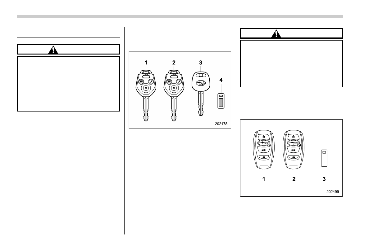
(102,1)
北米Model "A1700BE-B" EDITED: 2017/ 10/ 11
Keys
CAUTION
When traveling in an airplane, do not
press the button of the key. If any
button of the key is pressed, radio
waves are emitted and may affect
the operation of the airplane. When
carrying the key in a bag, take
measures to prevent the buttons
from being pressed accidentally.
NOTE
Press the buttons of the key to lock/
unlock with the remote keyless entry
system. For details, refer to “Remote
keyless entry system” F2-18.
& Models without “keyless ac-
cess with push-button start
system”
1) Master key
2) Submaster key
3) Sub key
4) Key number plate
Three types of keys are provided for your
vehicle.
CAUTION
Do not attach a large key holder or
key case to either key. If it bangs
against your knees while you are
driving, it could turn the ignition
switch from the “ON” position to
the “ACC” or “LOCK” position,
thereby stopping the engine.
& Models with “keyless access
with push-button start sys-
tem”
1) Access key fob (main)
2) Access key fob (sub)
3) Key number plate
The vehicle has two access key fobs and a
Keys and doors/Keys
2-2
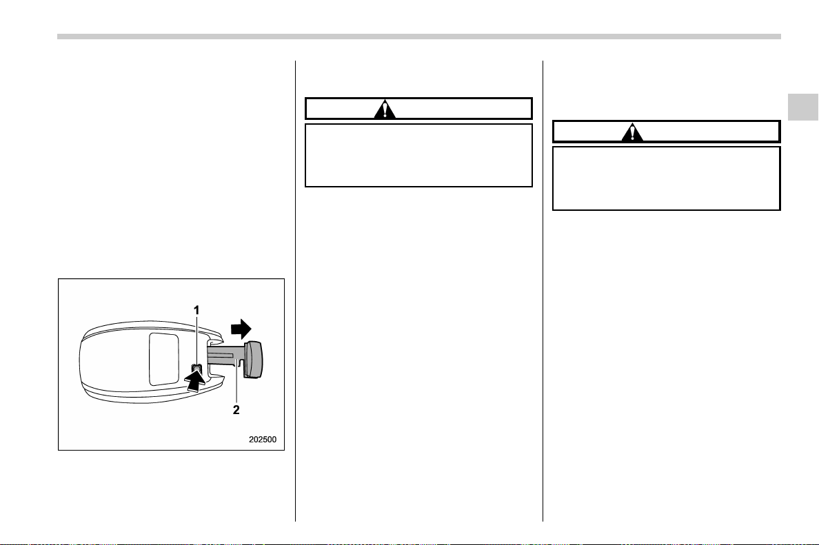
(103,1)
北米Model "A1700BE-B" EDITED: 2017/ 10/ 11
key number plate. For details about the
key number plate, refer to “Key number
plate” F2-3.
An emergency key is attached to each
access key fob. The emergency key is
used for the following operations.
. Locking and unlocking the driver’s door
. Locking and unlocking the glove box
You cannot unlock the glove box without
using the emergency key. You can keep
the glove box locked when you leave your
vehicle and the access key fob (with the
emergency key removed) at a parking
facility.
1) Release button
2) Emergency key
While pressing the release button of the
access key fob, take out the emergency
key.
CAUTION
If the access key fob is dropped, the
integrated emergency key inside
may become loose. Be careful not
to lose the emergency key.
NOTE
. The access key fob is always com-
municating with the vehicle and is
continuously using the battery.
Although the life of the battery varies
depending on the operating conditions,
it is approximately 1 to 2 years. If the
battery becomes fully discharged, re-
place it with a new one.
. If an access key fob is lost, it is
recommended that the remaining ac-
cess key fobs be re register ed. For
reregistration of an access key fob,
contact a SUBARU dealer.
. Up to 7 access key fobs can be
registered for one vehicle. For a spare
access key fob, contact a SUBARU
dealer.
. Do not leave the access key fob in
the storage spaces inside the vehicle.
Vibrations can damage the key or turn
on the switch, possibly resulting in a
lockout.
& Key number plate
CAUTION
Carefully store t he key numb er
plate. It is necessa ry for vehicle
repair and additional registration of
access key fobs.
The key number is stamped on the key
number plate attached to the key set. Write
down the key number and keep it in
another safe place, not in the vehicle. This
number is needed to make a replacement
key if you lose your key or lock it inside the
vehicle. Refer to “Key replacement” F2-
23.
Keys and doors/Keys
2-3
2
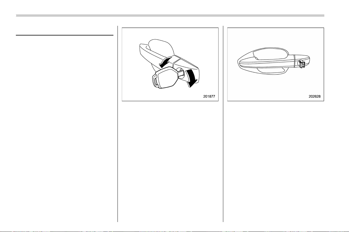
(104,1)
北米Model "A1700BE-B" EDITED: 2017/ 10/ 11
Door locks
& Locking and unlocking from
the outside
NOTE
If you unlock the driver’s door with a
key (including an emergency key) and
open the door while the alarm system is
armed, the alarm system is triggered
and the vehicle’s horn sounds. In this
case, perform any of t he following
operations:
Models wi th “keyless ac cess wi th
push-button start system”:
. Press any button on the access key
fob (except when the battery of the
access key fob is discharged).
. Turn the push-button ignition switch
to the “ACC” position.
Models without “keyless access with
push-button start system”:
. Press any button on the remote
transmitter (except when the transmit-
ter battery is discharged).
. Insert the key into the ignition switch
and turn the ignition switch to the “ON”
position.
For details about the alarm system,
refer to “Alarm system” F2-24.
To lock the driver’s door from the outside
with the key, turn the key toward the front.
To unlock the door, turn the key toward the
rear. Pull the outside door handle to open
an unlocked door.
NOTE
The emergency key is directional. If the
key cannot be inserted, change the
direction that the grooved side is facing
and insert it again.
To lock the door from outside without the
key, the following methods are available.
Keys and doors/Door locks
2-4
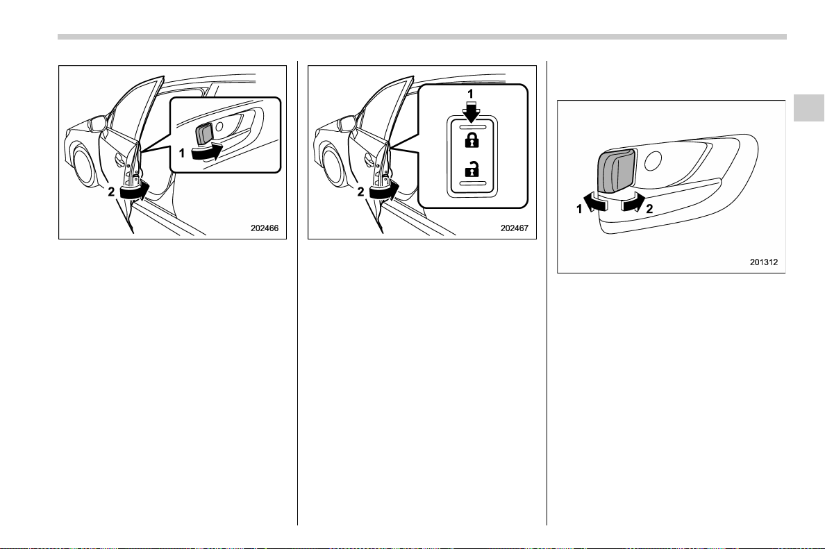
(105,1)
北米Model "A1700BE-B" EDITED: 2017/ 10/ 11
Locking using lock lever
1) Rotate the lock lever forward.
2) Close the door.
Locking using power door locking switch
1) Press the front side (lock side) of the
power door locking switch.
2) Close the door.
In this case, all closed doors are locked at
the same time.
Always make sure that all doors and the
trunk lid are locked before leaving your
vehicle.
NOTE
Make sure that you do not leave the key
inside the vehicle when locking the
doors from the outside without the key.
& Locking and unlocking from
the inside
1) Unlock
2) Lock
To lock the door from the inside, rotate the
lock lever forward. To unlock the door from
the inside, rotate the lock lever rearward.
The red mark on the lock lever appears
when the door is unlocked.
Pull the inside door handle to open an
unlocked door.
Always make sure that all doors and the
trunk lid are closed before starting to drive.
– CONTINUED –
Keys and doors/Door locks
2-5
2
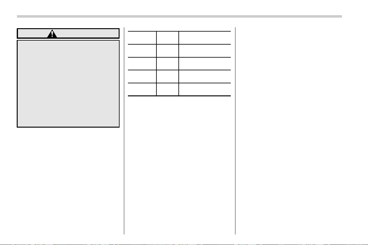
(106,1)
北米Model "A1700BE-B" EDITED: 2017/ 10/ 11
WARNING
Keep all doors lock ed wh en you
drive, especially when small chil-
dren are in your vehicle.
Along with the proper use of seat-
belts and child restraints, locking
the doors reduces the chance of
being thrown out of the vehicle in an
accident.
It also helps prevent passengers
from falling out by preventing a door
from being accidentally opened, and
intruders from unexpectedly open-
ing doors and entering your vehicle.
& Battery drainage prevention
function
If a door is not completely closed, the
interior lights will remain illuminated as a
result. However, several lights will be
automatically turned off by the battery
drainage prevention function to prevent
the battery from discharging. The following
interior lights will be affected by this
function.
Item
Switch
position
Automatically turning
off
Map lights* OFF*
Approximately 20
minutes later
Dome light DOOR
Approximately 20
minutes later
Ignition
switch light
—
Approximately 20
minutes later
Trunk light —
Approximately 20
minutes later
*: The battery drainage prevention function
affects only the map lights on models with the
moonroof, and only when the map light switches
are in the OFF position. The map lights on
models without the moonroof do not turn off
automatically, so push the light switches manu-
ally to turn them off.
The operational/non-operational setting of
this function can be changed by a
SUBARU dealer. Contact your SUBARU
dealer to change the setting.
NOTE
. The factory setting (default setting)
for this function is set as “operational”.
. When leaving the vehicle, make sure
that all doors and the trunk lid are
completely closed.
. The battery drainage prevention
function does not operate while the
key is in the ignition switch.
Keys and doors/Door locks
2-6
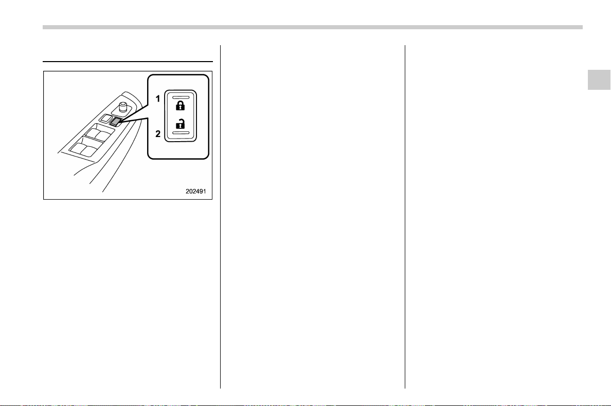
(107,1)
北米Model "A1700BE-B" EDITED: 2017/ 10/ 11
Power door locking switches
1) Lock
2) Unlock
All doors can be locked and unlocked by
the power door locking switches located at
the driver’s side and the front passenger’s
side doors.
To lock the doors, push the front side of the
switch.
To unlock the doors, push the rear side of
the switch.
When you close the doors after you set the
door locks, the doors remain locked.
NOTE
Make sure that you do not leave the key
inside the vehicle before locking the
doors from the outside using the power
door locking switches.
& Key lock-in prevention func-
tion
This func tion prevents the doors from
being locked under the following condi-
tions.
. The key is still in the ignition switch
(models without “keyless access with
push-button start system”)
. The ignition switc h is in the “ON ”
position (models with “keyless access with
push-button start system”)
This function’s operational/non-opera-
tional setting can be changed by a
SUBARU dealer. Contac t a SUBARU
dealer for details.
NOTE
. The factory setting (default setting)
for this function is set as “operational”.
. When leaving the vehicle, make sure
you are holding the key before locking
the doors.
! Behavior with key lock-in preven-
tion function operational
With the driver’s door open, the doors are
automatically kept unlocked even if the
front side of the power door locking switch
is pressed.
! Behavior with key lock-in preven-
tion function non-operational
. If the lock lever is turned to the front
(“LOCK”) position with the driver’s door
open and the driver’s door is then closed
with the lock lever in that position, the
driver’s door is locked.
. If the spare key is used to lock the
driver ’s door from the outside of the
vehicle, the door is locked.
Keys and doors/Power door locking switches
2-7
2
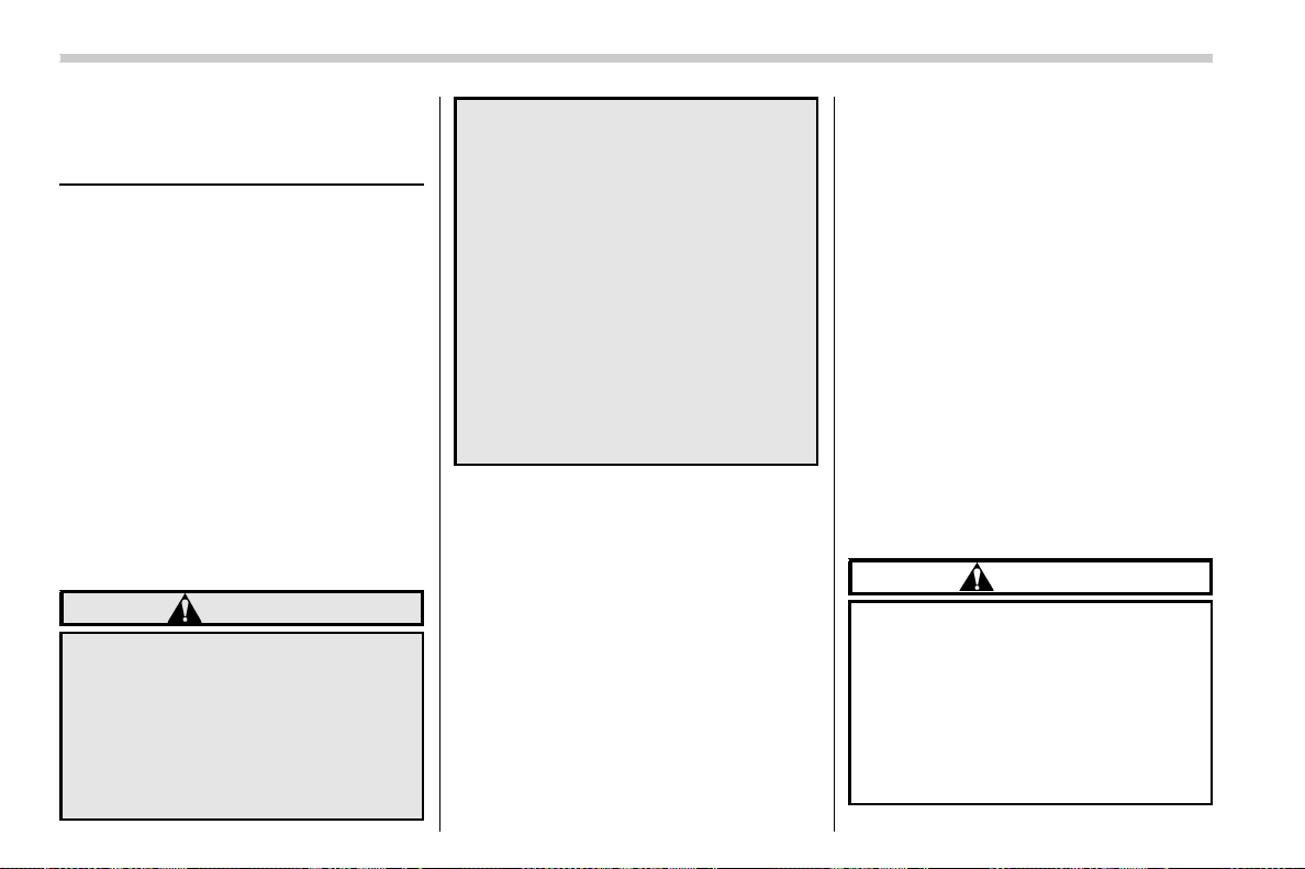
(108,1)
北米Model "A1700BE-B" EDITED: 2017/ 10/ 11
Keyless access with push-
button start system (if
equipped)
You can perform the following operations
using “keyless access with push-button
start system” when you are holding the
access key fob.
. Locking and unlocking of the doors
. Opening the trunk
. Starting and stopping the engine. For
details, refer to “Models with push-button
start systems” F7-11.
. Arming and disarming the alarm sys-
tem. For details, refer to “Alarm system”
F2-24.
& Safety precautions
! Regarding radio wave
WARNING
If you wear an implanted pacemaker
or an implanted defibrillator, stay at
least 8.7 in (22 cm) away from the
transmitting antennas installed on
the vehicle.
The radio waves from the transmit-
ting antennas on the vehicle could
adversely affect the operation of
implanted pacemakers and im-
planted defibrillators.
If you wear electric medical equip-
ment other than an implanted pace-
maker or an implanted defibrillator,
before using the keyless a ccess
with push-button start system, refer
to “Radio waves used for the key-
less access with push-button start
system” F2-9, and contact the elec-
tric medical equipment manufac-
turer for more information. The radio
waves from the transmitting anten-
nas on the vehicle could adversely
affect the operation of the electric
medical equipment.
NOTE
The status of the access key fob and
environmental conditions may interfere
with the communication between the
access key fob and the vehicle under
the following conditions.
. When you operate near a source of
strong radio waves or other interfer-
ence, such as a broadcast station or
power transmission lines
. When products that transmit radio
waves are used, such as an access key
fob or a remote transmitter key fob of
another vehicle
. When you carry the access key fob
of your vehicle together with an access
key fob or a remote transmitter of
another vehicle
. When the access key fob is placed
near wireless communication equip-
ment such as a cell phone, or near a
metallic object
. When metallic accessories are at-
tached to the access key fob
. When you carry the access key fob
with electronic appliances such as a
laptop computer
. When the battery of the access key
fob is discharged
In such cases, it may not be possible to
lock or unlock the doors or start the
engine.
! Regarding malfunction
CAUTION
. Never leave or store the access
key fob inside the vehicle or
within 6.6 ft (2 m) around the
vehicle (e.g., in the garage). The
access key fob may be locked
inside the vehicle, or the battery
may discharge rapidly. Note that
the push-button ignition switch
may not turn on in some cases
Keys and doors/Keyless access with push-button start system
2-8
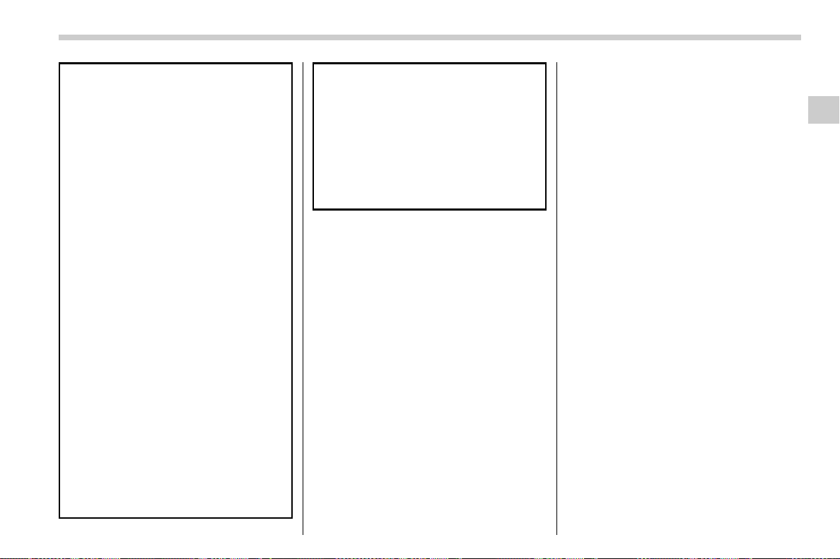
(109,1)
北米Model "A1700BE-B" EDITED: 2017/ 10/ 11
depending on the location of the
access key fob.
. The access key fob contains
electronic components. Observe
the following precautions to pre-
vent malfunctions or battery dis-
charge.
– It is recommended that the
battery be replaced by a
SUBARU dealer to avoid the
damage at the time of replace-
ment.
– Do not get the access key fob
wet. If the access key fob gets
wet, wipe it off immediately
and let it dry completely.
– Do not apply strong impacts to
the access key fob.
– Never leave the access key
fob in direct sunlight or any-
where that may become hot,
such as on the dashboard.
– Do not wash the access key
fob in an ultrasonic washer.
– Do not leave the access key
fob in humid or dusty loca-
tions, or near personal com-
puters or home electric appli-
ances.
– Keep the access key fob away
from magnetic sources.
– Do not leave the access key
fob near a battery charger or
any electrical accessories.
– Do not apply metallic window
tint or attach metallic objects
to the windows.
– Do not fit non genuine acces-
sories or parts.
NOTE
After the vehicle battery is discharged
or replaced, initialization of the steering
lock system may be required to start
the engine. In this case, perform the
following procedure to initialize the
steering lock.
1) Turn the push-button ignition
switch to the “OFF” position. For de-
tails, refer to “Switching power status”
F3-7.
2) Open and close the driver’s door.
3) Wait for approximately 10 seconds.
When the steering is locked, the initi-
alization is completed.
! Regarding setting
NOTE
. You can change the operational/non-
operational setting for the keyless
access function. For the setting proce-
dure, refer to “Disabling keyless ac-
cess function” F2-14. The setting can
also be changed by a SUBARU dealer.
For more details, contact a SUBARU
dealer.
. For detailed information about the
operation method for the push-button
ignition switch while the keyless ac-
cess function is switched to the non-
operational mode, refer to “Access key
fob – if access key fob does not operate
properly” F9-26.
! Radio waves used for the keyless
access with push-button start sys-
tem
The keyless access with push-button start
system uses radio waves of 134 kHz, in
addition to the radio waves used for the
remote keyless entry system. The radio
waves are periodically output from the
antennas installed on the vehicle as shown
in the following illustration.
– CONTINUED –
Keys and doors/Keyless access with push-button start system
2-9
2
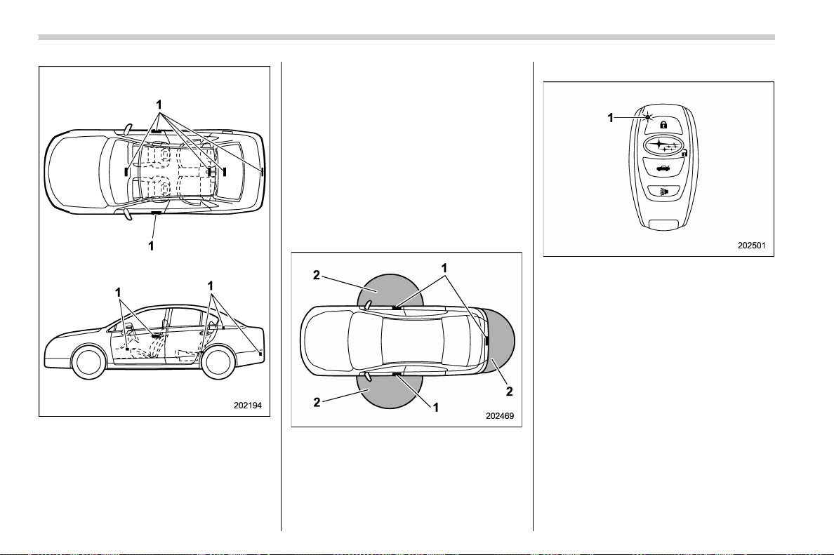
(110,1)
北米Model "A1700BE-B" EDITED: 2017/ 10/ 11
1) Antenna
& Locking and unlocking by
holding the access key fob
With the access key fob carried within the
operating range, you can lock/unlock the
doors just by touching the door handle.
NOTE
You can lock/unlock the vehicle with
the remote keyless entry system. For
details, refer to “Remote keyless entry
system” F2-18
! Operating ranges
1) Antenna
2) Operating range
The operating ranges of the door locking/
unlocking functions and the trunk lid open-
ing function are approximately 16 to 32 in
(40 to 80 cm) from the respective door
handles and the trunk ornament.
1) LED indicator
When the access key fob is within either of
the operating ranges of the front doors, the
LED indicator on the access key fob
flashes. When the keyless access func-
tions are disabled, the LED indicator does
not flash unless a button on the access key
fob is pressed.
Keys and doors/Keyless access with push-button start system
2-10
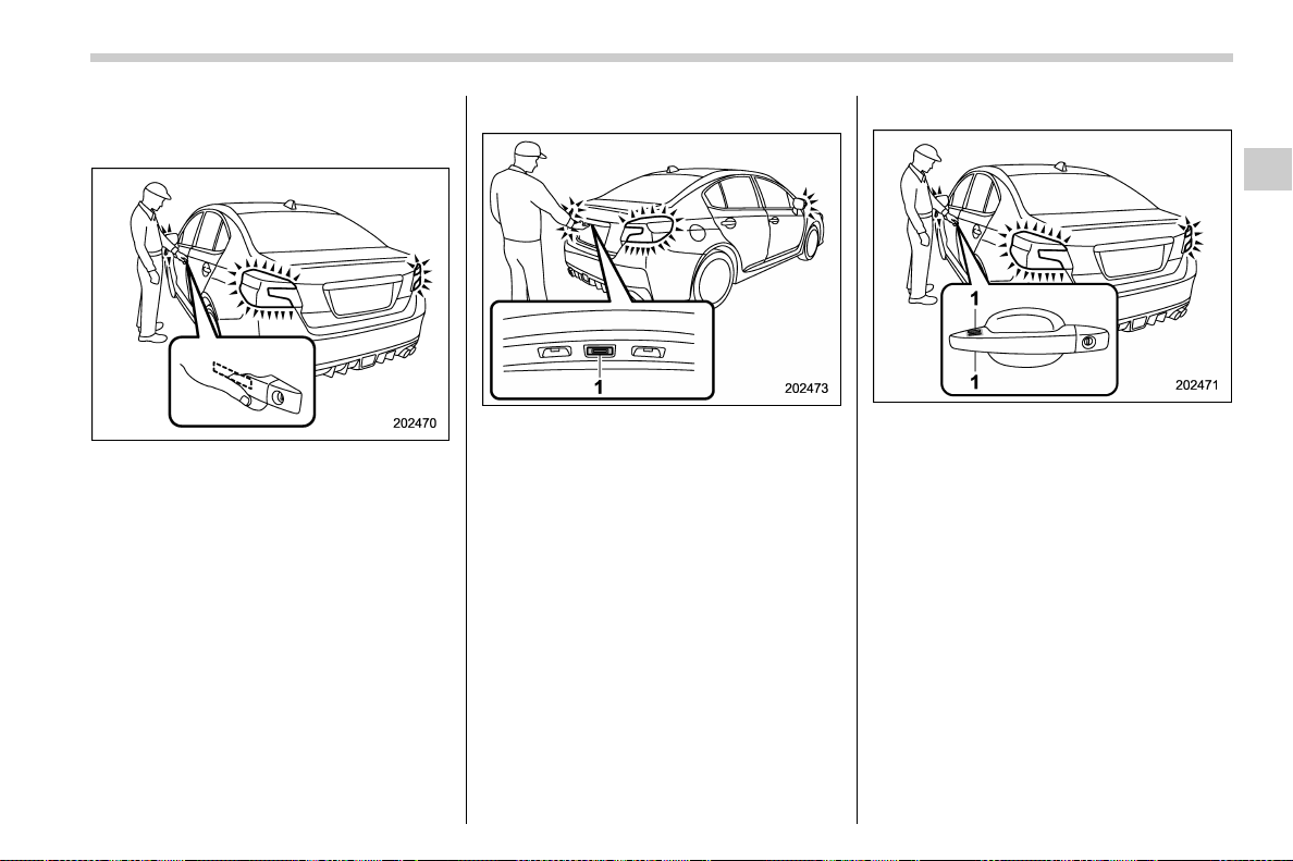
(111,1)
北米Model "A1700BE-B" EDITED: 2017/ 10/ 11
! How to lock and unlock
! Unlocking
Carry the access key fob, and grip the door
handle.
. When the driver ’s door handle is
gripped, only the driver’s door will be
unlocked.
. When the front passenger’s door han-
dle is gripped, all doors will be unlocked.
Also, an electronic chirp will sound twice
and the hazard warning flashers will flash
twice.
! Opening trunk
1) Trunk opener button
Carry the access key fob, and press the
trunk opener button.
. Only the trunk lid will be unlocked and
opened.
. An electronic chirp will sound twice and
the hazard warning flashers will flash
twice.
! Locking
1) Door lock sensor (above and below)
Carry the access key fob, close all doors
and the trunk lid and touch the door lock
sensor on the door handle.
. All doors will be locked.
. An electronic chirp will sound once and
the hazard warning flashers will flash once
NOTE
After touching the door lock sensor to
lock all of the doors, if you touch the
door lock sensor once more to attempt
the lock operation without first unlock-
ing the doors, nothing will happen,
even if the door lock sensor is touched.
In this case, perform the unlocking
operation once first. You can then
touch the door lock sensor to lock the
– CONTINUED –
Keys and doors/Keyless access with push-button start system
2-11
2
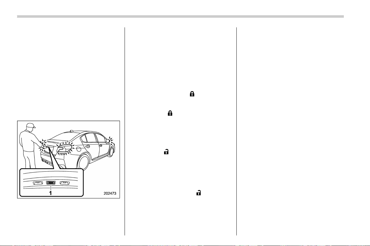
(112,1)
北米Model "A1700BE-B" EDITED: 2017/ 10/ 11
doors.
! Door unlock selection function
You can unlock only the door(s) that has/
have been selected.
You can change the setting as follows.
. Operate the multi-function display (col-
or LCD). For details, refer to “Keyless
Access setting” F3-62
. Have the setting changed by a
SUBARU dealer.
& Unlock using PIN Code Ac-
cess
1) Trunk opener button
While all doors are locked, you can unlock
the doors without a key by operating the
trunk opener button.
NOTE
PIN Code Access will be helpful if the
key is accidentally left in the vehicle. It
is recommended that a 5-digit security
code (PIN code) is registered.
! Preparation for registering a PIN
code
1. Close all doors (including the trunk).
2. Press and hold the “
” button on the
access key fob. Then all doors (including
the trunk) will be locked.
3. Keep the “
” button pressed, and
press the trunk opener button within 5
seconds after step 2.
4. Press and hold the trunk opener button
for more than 5 seconds. Then a chirp will
sound.
5. Press the “
” button on the access key
fob while the chirp sounds.
Then the chirp will stop and the prepara-
tion is complete.
NOTE
If you do not press the “ ” button on
the access key fob, the chirp will sound
for 30 seconds. In this case, the pre-
paration for registering a PIN code does
not complete even if the chirp stops.
! Registration for a PIN code
For example, to register “32468” as the
PIN code, perform the following proce-
dure.
1. Press the trunk opener button three
times.
2. After a buzzer (ding) sounds once,
press the trunk opener button twice.
3. After a buzzer (ding) sounds once,
press the trunk opener button four times.
4. After a buzzer (ding) sounds once,
press the trunk opener button six times.
5. After a buzzer (ding) sounds once,
press the trunk opener button eight times.
6. Perform step s 1 to 5 again within
approximately 30 seconds after the buzzer
starts sounding intermittently.
7. All doors will be unlocked and locked.
Then the PIN code will be registered.
NOTE
. Ifyoumakeanerrorduringthe
registration procedure, open the dri-
ver’s door and then close it. Then, start
over from the procedure described in
“Preparation”.
. To protect your vehicle from theft,
you cannot register “00000”, “11111” to
“99999” or “12345” as a PIN code.
. Do not register your vehicle license
Keys and doors/Keyless access with push-button start system
2-12

(113,1)
北米Model "A1700BE-B" EDITED: 2017/ 10/ 11
plate number or simple numbers such
as “11122” or “12121” as a PIN code.
Doing so will increase the risk of
vehicle theft.
. When you try to register “22222”, the
registered PIN code will be deleted. You
cannot unlock the doors by PIN Code
Access until a new code is registered.
. After registering a new PIN code,
make sure that you can unlock the
doors using the PIN code.
. When you delete the PIN code while
the keyless access function is dis-
abled, the keyless access function will
be enabled.
. Reregister the PIN code in the fol-
lowing case.
– when you forget the PIN code
– when you want to change the PIN
code
! Unlocking
Perform steps 1 to 5 described in “Regis-
tration”.
NOTE
. You cannot unlock by PIN Code
Access in the following cases.
– when the access key fob is within
the operating ranges
– when the ignition switch is in the
“ACC” or “ON” position
. If you make an operation error dur-
ing the unlocking procedure, start over
with the unlocking procedure after
waiting for 5 seconds or longer.
. To protect your vehicle from theft, a
buzzer will sound if incorrect PIN codes
are entered five times continuously. If
this occurs, you cannot unlock the
doors by PIN Code Access f or 5
minutes.
& Power saving function
The keyless access function will be dis-
abled in the following cases to protect the
battery of the access key fob and the
vehicle battery.
Case 1: When the keyless access function
and the remote keyless entry system have
not been used for 2 weeks or longer while
all doors are locked
Case 2: When the access key fob has
been left in the operating range for 10
minutes or longer while all doors are
locked
! Recovery from power saving mode
When one of the following is operated, the
keyless access function will be recovered.
Case 1:
. Unlock the doors by operating any
procedure other than gripping the front
passenger’s door handle
. Lock or unlock the doors
. Open a door and then close it
Case 2:
. Unlock the doors by gripping the door
handle
. Lock the doors by touching the door
lock sensor
. Lock or unlock the doors by using the
remote keyless entry system
. Lock or unlock the doors by using the
power door locking switch
. Open either of the front doors
– CONTINUED –
Keys and doors/Keyless access with push-button start system
2-13
2

(114,1)
北米Model "A1700BE-B" EDITED: 2017/ 10/ 11
& Selecting audible signal op-
eration
Using an electronic chirp, the system will
give you an audible signal when the doors
lock and unlock. If desired, you may
change the volume of the audible signal
or turn it off. For details, refer to “Keyless
buzzer volume setting” F3-61.
& Warning chimes and warning
indicator
The warning chime and the access key
warning light serve the following purposes:
. To minimize improper operation of the
keyless access with push-button start
system
. To protect your vehicle from theft
For details, refer to “Warning chimes and
warning indicator of the keyless access
with push-button start system” F3-28.
& Disabling keyless access
function
WARNING
If you wear an implanted pacemaker
or an implanted defibrillator, operate
the driver’s door to disable the key-
less access function. Otherwise, the
operation of an implanted pace-
maker or implanted defibrillator
may be affected by the radio waves
from the transmitter antenna.
When the vehicle is not going to be used
for a long time, or when you choose not to
use the keyless access function, the key-
less access function can be disabled.
NOTE
. The locking and unlocking function
by the remote keyless entry system is
not disabled.
. The setting can also be changed at
SUBARU dealers. For more details,
contact a SUBARU dealer.
. To start the engine while the func-
tions are disabled, perform the proce-
dure described in “Starting engine”
F9-27.
. We recommend that you disable the
keyless access functi ons under the
following conditions.
– When the vehicle is not going to
be used for an extended period of
time
– When the keyless access func-
tions are not going to be used
! Disabling functions
! By operating the access key fob
If you have registered a PIN code for PIN
Code Access, you can disable the keyless
access function by operating the access
key fob. For details about registering a PIN
code, refer to “Registration for a PIN code”
F2-12.
1. Open the driver’s door.
2. Rotate the lock lever forward.
Keys and doors/Keyless access with push-button start system
2-14
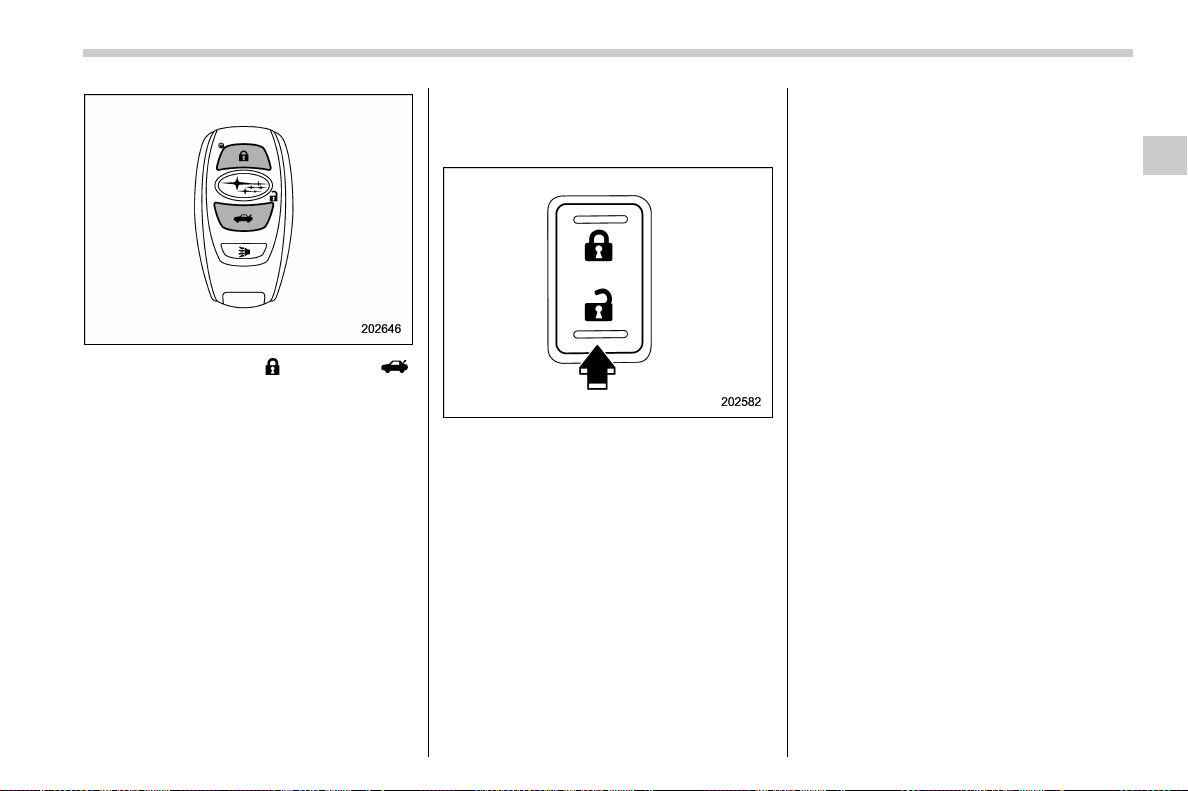
(115,1)
北米Model "A1700BE-B" EDITED: 2017/ 10/ 11
3. Press and hold the “ ” button and “ ”
button on the access key fob simulta-
neously for more than 5 seconds.
A chirp sound will be heard, and the
function will be disabled.
! By operating the driver’s door
1. Sit in the driver’s seat, and close the
door.
2. Push the rear side (unlock side) of the
power door locking switch.
3. Within 5 seconds after step 2 is
performed, open the driver’s door.
4. Within 5 seconds after step 3 is
performed, push the rear side (unlock
side) of the power door locking switch
twice while the door is open.
5. Within 10 seconds after step 4 is
performed, close and open the driver ’s
door twice.
6. Within 10 seconds after step 5 is
performed, push the rear side (unlock
side) of the power door locking switch
twice while the door is open.
7. Within 10 seconds after step 6 is
performed, close and open the driver ’s
door once.
8. Within 5 seconds after step 7 is
performed, close the door. A chirp sound
will be heard, and the functions will be
disabled.
NOTE
In steps 4 and 6, press the power door
locking switch slowly. If the switch is
pressed quickly, the functions may not
be disabled.
! Enabling functions
When the procedure to disable the func-
tions is performed again, the functions are
enabled.
NOTE
. The keyless access function will be
enabled only if you perform the proce-
dure in the same manner you disabled
the function (for example, when dis-
abling by operating the driver’s door,
the function will not be enabled even if
you operate the access key fob).
. Press the push-button ignition
switch if you do not know the proce-
dure in which the keyless access func-
tion was disabled.
– When disabling by operating the
– CONTINUED –
Keys and doors/Keyless access with push-button start system
2-15
2
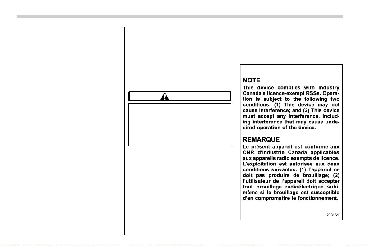
(116,1)
北米Model "A1700BE-B" EDITED: 2017/ 10/ 11
driver’s door: a chirp will not be
heard
– When disabling by operating the
access key fob: a chirp will be heard
& When access key fob does
not operate properly
Refer to “Access key fob – if access key
fob does not operate properly” F9-26.
& Replacing battery of access
key fob
Refer to “Replacing battery of access key
fob” F11-52.
& Replacing access key fob
Access key fobs can be replaced at
SUBARU dealers. For more details, con-
tact a SUBARU dealer.
& Certification for keyless ac-
cess with push-button start
system
! U.S.-spec. models
FCC ID: HYQ13CZZ
FCC ID: HYQ14AHC
FCC ID: Y8PSSPIMB02
FCC ID: Y8PSSPLF02
CAUTION
FCC WARNING
Changes or modifications not ex-
pressly approved by the party re-
sponsible for compliance could void
the user’s authority to operate the
equipment.
NOTE
This device complies with part 15 of the
FCC Rules. Operation is subject to the
following two conditions: (1) This de-
vice may not cause harmful interfer-
ence, and (2) this device must accept
any interference receiv ed, inclu din g
interference that may cause undesired
operation.
This device complies with part 15 of the
FCC Rules. Operation is subject to the
following two conditions: (1) This device
may not cause harmful interference, and
(2) this device must accept any interfer-
ence received, including interference that
may cause undesired operation.
! Canada-spec. models
Keys and doors/Keyless access with push-button start system
2-16
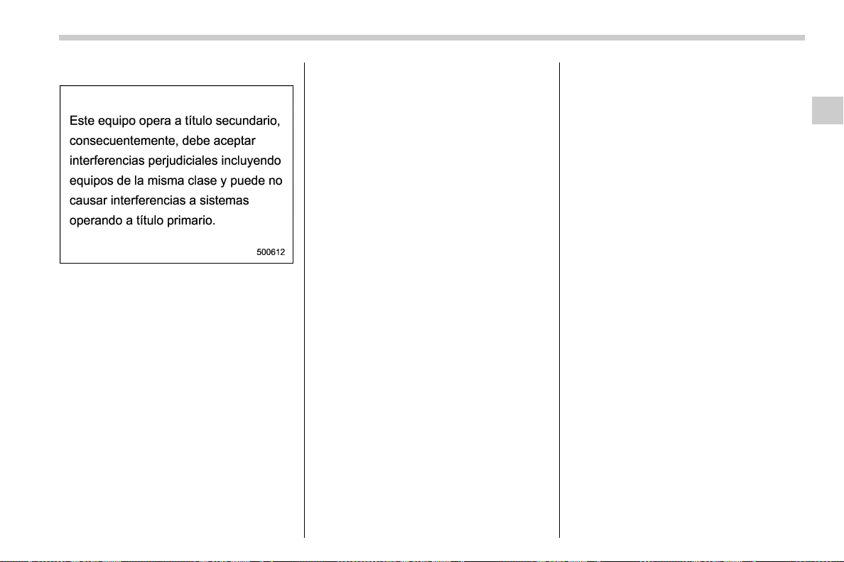
(117,1)
北米Model "A1700BE-B" EDITED: 2017/ 10/ 11
! Mexico-spec. models
IFT
RLVDE1413-2269
14AHC
DENSO
& Tips
! Operating range tips
Regarding malfunction:
The keyl ess access function may not
operate properly due to the following
reasons.
. The access key fob is placed too close
to the vehicle body (in this case, repeat the
operation from further away).
. The access key fob is placed near the
ground or in an elevated location from the
ground, even if it is in the operating range.
. The status of the access key fob and
the r adio wave conditions around the
vehicle (in this case, perform the proce-
dure described in “Locking and unlocking”
F9-26.)
Precautions:
. When the access key fob is within the
operating range, it is possible for anyone,
even someone who is not carrying the
access key fob, to operate the keyless
access function. Please note that the
keyless access function is only available
for the following items when the access
key fob is detected within operating range.
– Door handle
– Door lock sensor
– Trunk opener button
. It is not possible to lock the doors using
the key less access function when the
access key fob is inside the vehicle.
However, depending on the status of the
access key fob and the environmental
conditions, the access key fob may be
locked inside the vehicle. Before locking,
make sure that you have the access key
fob.
. The operating ranges may be reduced,
or the keyless access function may not
operate in the following cases:
– When the battery of the access key
fob is discharged
– When the access key fob is in a
location with strong radio waves or
noise (e.g., near a radio tower, power
plant, broadcast station or an area
where wireless equipment is used)
– While talking on a cell phone
In such a case, perform the procedure
described in “Locking and unlocking” F 9-
26
. When an access key fob is in the
operating range, if the door handle be-
comes wet due to exposure to a significant
amount of water when the vehicle is
washed or during heavy rain, the doors
may be locked or unlocked.
! Keyless access function tips
. Turn off the push-button ignition switch
before locking the doors using the keyless
access function. It is not possible to lock
the doors using the keyless access func-
tion when the push-button ignition switch is
on the “ACC” or “ON” position. For details
about turning off the push-button ignition
switch, refer to “Switching power status”
F3-7.
. If the door handle is gripped or the door
lock sensor is touched with a gloved hand,
the doors may not be locked or unlocked.
. If the door lock sensor is touched three
times or more repeatedly, the system will
– CONTINUED –
Keys and doors/Keyless access with push-button start system
2-17
2
(118,1)
北米Model "A1700BE-B" EDITED: 2017/ 10/ 11
ignore the sensor operation.
. When performing the locking proce-
dure too quickly, doors may not be locked.
After the locking procedures, it is recom-
mended to pull the REAR door handles to
confirm that the doors have been locked.
. It is possible to lock the doors even
when one of the doors is open. After
performing the locking procedure, close
the opened door to lock it.
. Within 3 seconds after lo cking the
doors by touching the door lock sensor, it
is not possible to unlock doors by gripping
the door handle.
. When locking, be sure to carry the
access key fob to prevent locking the
access key fob in the vehicle.
. The settings of the hazard warning
flasher operation and the volume of the
audible signal can be changed by your
SUBARU dealer. Contact your SUBARU
dealer for details. You can also change the
setting of the hazard warning flasher
operation by operating the multi-function
display (color LCD). For details, refer to
“Hazard warning flasher setting ” F3-61.
Remote keyless entry system
CAUTION
. Do not expose the remote trans-
mitter to severe shocks, such as
those experienced as a result of
dropping or throwing.
. Do not take the remote transmit-
ter apart except when replacing
the battery.
. Do not get the remote transmitter
wet. If it gets wet, wipe it dry with
a cloth immediately.
. When you carry the remote trans-
mitter on an airplane, do not
press the button of the remote
transmitter while in the airplane.
When any button of the remote
transmitter is pressed, radio
waves are sent and may affect
the operation of the airplane.
When you carry the remote trans-
mitter in a bag on an airplane,
take measures to prevent the
buttons of the remote transmitter
from being pressed.
For models with “keyless access with
push-button start system”, the access
key fob is used as the transmitter for the
remote keyless entry system. For models
without “keyless access with push-button
start system”, the transmitter for the
remote keyless entry system is located
inside the key head.
The remote keyless entry system has the
following functions.
. Locking and unlocking the doors with-
out a key
. Opening the trunk without a key
. Sounding a panic alarm
. Arming and disarming the alarm sys-
tem. For detail ed information, refer to
“Alarm system” F2-24.
The operable distance of the remote key-
less entry system is approximately 30 feet
(10 meters). However, this distance will
vary depending on environmental condi-
tions. The system’s operable distance will
be shorter in areas near a facility or
electronic equipment emitting strong radio
waves such as a power plant, broadcast
station, TV tower, or remote controller of
home electronic appliances.
NOTE
. For models with “keyless access
with push-button start system”,the
remote keyless entry system will not
be activated when the push-button
ignition switch is in any position other
Keys and doors/Remote keyless entry system
2-18
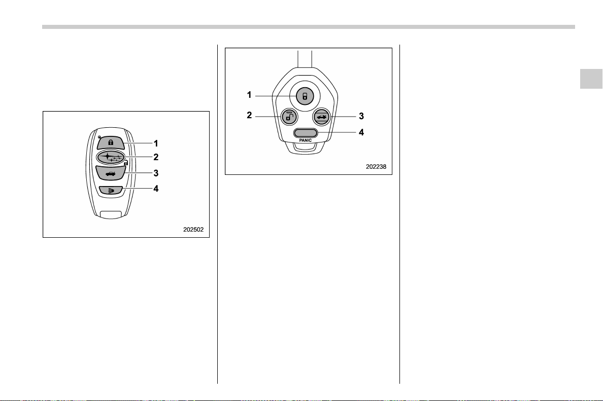
(119,1)
北米Model "A1700BE-B" EDITED: 2017/ 10/ 11
than the “OFF” position.
. For models without “keyless access
with push-button start system”,the
remote keyless entry system will not
be activated when the key is inserted in
the ignition switch.
Access key fob
1) Lock/arm button
2) Unlock/disarm button
3) Trunk opener button
4) PANIC button
Transmitter
1) Lock/arm button
2) Unlock/disarm button
3) Trunk opener button
4) PANIC button
NOTE
The hazard warning flashers will flash
once or twice when the transmitter
button is pressed in t he following
cases.
– When locking the doors
– When unlocking the doors
– When unlocking the trunk lid
Operation of the hazard warning
flashers in the above cases can be set
to “On” or “Off” by a SUBARU dealer.
Consult your SUBARU dealer for de-
tails. Also, you can change the setting
using the multi-function display (color
LCD).Fordetails,referto“Hazard
warning flasher setting” F3-61.
& Locking the doors
Press the lock/arm button to lock all doors.
An electronic chirp will sound once and the
hazard warning flashers will flash once.
If any of the doors or the trunk lid is not fully
closed, an electronic chirp will sound five
times and the hazard warning flashers will
flash five times to alert you that the doors
(or the trunk lid) are not properly closed.
When you close the door, it will automati-
cally lock and then an electronic chirp will
sound once and the ha zard warning
flashers will flash once.
& Unlocking the doors
Press the unlock/disarm button to unlock
the driver’s door. An electronic chirp will
sound twice and the hazard warning
flashers will flash twice. To unlock all
doors, briefly press the unlock/disarm
button a second time within 5 seconds.
– CONTINUED –
Keys and doors/Remote keyless entry system
2-19
2
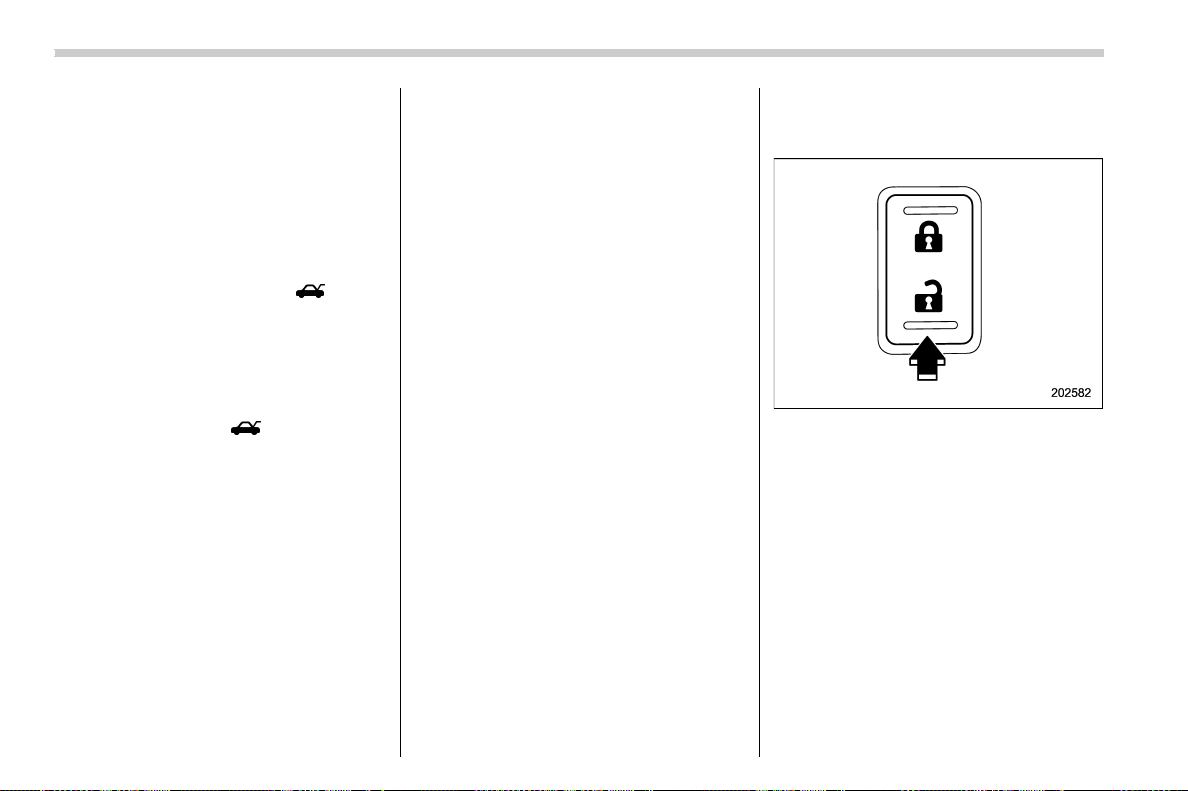
(120,1)
北米Model "A1700BE-B" EDITED: 2017/ 10/ 11
NOTE
If the interval between the first and
second presses of the unlock/disarm
button (for unlocking of all of the doors)
is extremely short, the system may not
respond.
& Opening the trunk lid
The trunk lid opens when the “ ” button
is press ed continuously for at least 2
seconds. An electronic chirp will sound
twice and the turn signal lights will flash
twice.
NOTE
You can disable the “ ” button on the
access key fob/transmitter. Contact
your SUBARU dealer to change the
setting.
& Vehicle finder function
Use t his function to find your vehicle
parked among many vehicles in a large
parking lot. Provided you are within 30 feet
(10 meters) of the vehicle, pressing the
lock/arm button three times in a 5-second
period will cause your vehicle ’s horn to
sound once and its hazard warnin g
flashers to flash three times.
NOTE
If the interval between presses is too
short when you press the lock/arm
button three times, the system may
not respond to the signals from the
access key fob/remote transmitter.
& Sounding a panic alarm
To activate the alarm, press the “PANIC”
button once.
The horn will sound and the hazard
warning flashers will flash.
To deactivate the panic alarm, press any
button on the access key fob/remote
transmitter. Unless a button on the access
key fob/remote transmitter is pressed, the
alarm will be deactivated after approxi-
mately 30 seconds.
& Selecting audible signal op-
eration (models without
“keyless access with push-
button start system”)
Using an electronic chirp, the system will
give you an audible signal when the doors
lock and unlock. If desired, you may turn
the audible signal off.
Perform the following steps to deactivate
the audible signal. You can also use the
same steps to restore the function.
1. Sit in the driver’s seat and shut all
doors and the trunk.
2. Hold down the REAR (UNLOCK) side
of the power door locking switch.
3. While holding down the REAR (UN-
LOCK) side of the power door locking
switch, pull the key out and re-insert it into
the ignition switch at least 6 times within 10
seconds after Step 2.
4. Open and close the driver ’s door once
within 10 seconds after Step 3.
5. The hazard warning flashers flash 3
times to indicate completion of the setting.
You may have the above settings done by
your SUBARU dealer. Also, the setting can
be changed using the multi-function dis-
play (color LCD). For details, refer to
Keys and doors/Remote keyless entry system
2-20
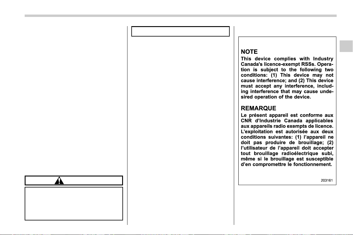
(121,1)
北米Model "A1700BE-B" EDITED: 2017/ 10/ 11
“Keyless buzzer volume setting ” F3-61.
You may also change the volume of the
audible signal by operating the multi-
function display (color LCD).
& Replacing the battery
Refer to “Replacing battery” F11-51.
& Replacing lost transmitters
If you lose a transmitter or want to
purchase additional transmitters (up to
four can be programmed), your transmit-
ters should be reprogrammed for security
reasons. For details, contact your
SUBARU dealer and have the transmitters
programmed into the remote keyless entry
system.
& Certification for Remote key-
less entry system
! U.S.-spec. models
FCC ID: CWTWB1U811
FCC ID: CWTWD1U781
CAUTION
FCC CAUTION
Changes or modifications not ex-
pressly approved by the party re-
sponsible for compliance could void
the user’s authority to operate the
equipment.
NOTE
This device complies with part 15 of the
FCC Rules. Operation is subject to the
following two conditions: (1) This de-
vice may not cause harmful interfer-
ence, and (2) this device must accept
any interference receiv ed, inclu din g
interference that may cause undesired
operation.
This device complies with Part 15 of the
FCC Rules. Operation is subject to the
following two conditions: (1) This device
may not cause harmful interference, and
(2) this device must accept any interfer-
ence received, including interference that
may cause undesired operation.
! Canada-spec. models
– CONTINUED –
Keys and doors/Remote keyless entry system
2-21
2

(122,1)
北米Model "A1700BE-B" EDITED: 2017/ 10/ 11
! Mexico-spec. models
COFETEL RCPSUTW13-2221
COFETEL RLVSU8813-2140
Anti-theft system
& Immobilizer
The immobilizer system is designed to
prevent an unauthorized person from
starting the engine. Only keys registered
with your vehicle’s immobilizer system can
be used to operate your vehicle. This
system, however, is not a 100% anti-theft
guaranty.
For models with “keyless access with
push-button start system”:
If you press the push-button ignition switch
when carrying an unregistered access key
fob, the switch will not turn to the “ON”
position and the engine will not start.
For models without “keyless access
with push-button start system”:
Even if an unregistered key fits into the
ignition switch and can be turned to the
“START” position, the engine will automa-
tically stop after several seconds.
If the engine does not start, perform either
of the following procedures.
. Perform the procedure described in
“Starting engine” F9-27 (models with
“keyless access with push-button start
system”).
. Pull out the key once before trying
again (models without “keyless access
with push-button start system”). Refer to
“Ignition switch” F3-4.
CAUTION
. Do not place the key under direct
sunlight or anywhere it may be-
come hot.
. Do not get the key wet. If the key
gets wet, wipe it dry with a cloth
immediately.
. Do not modify or r emove the
system. If modified or removed,
the proper operation of the sys-
tem cannot be guaranteed.
NOTE
. To protect your vehicle from theft,
please pay close attention to the follow-
ing security precautions:
– Never leave your vehicle unat-
tended with its keys inside.
– Before leavin g your vehicle,
close all windows and the moon-
roof, and lock the doors.
– Do not leave spare keys or any
record of your key number in the
vehicle.
. The vehicle has a maintenance-free
type immobilizer system.
Keys and doors/Anti-theft system
2-22
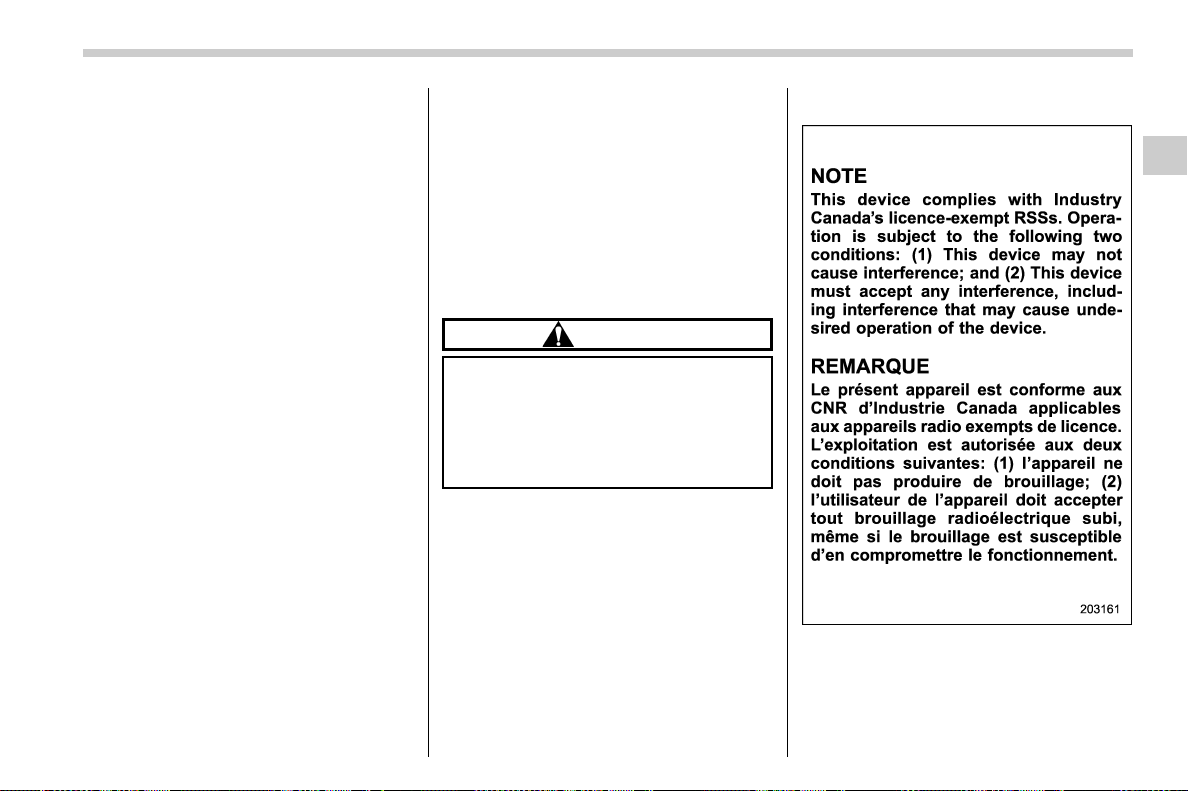
(123,1)
北米Model "A1700BE-B" EDITED: 2017/ 10/ 11
! Security indicator light
Refer to “Security indicator light” F3-33.
! Key replacement
Your key number plate will be required if
you ever need a replacement key made.
Any new key must be registered for use
with your vehicle’s immobilizer system
before it can be used. The maximum
number of keys that can be registered for
use with one vehicle is as follows.
. Four (models without “ keyless access
with push-button start system”)
. Seven (models with “keyless access
with push-button start system”)
One key that has already been registered
is required in order to register a new key.
If you lose a key, the lost key’s ID code still
remains in the memory of the vehicle’s
immobilizer system. For security reasons,
the lost key’s ID code should be erased
from the memory. To erase the lost key’sID
code, all keys that will be used are
required.
For details about new key registration and
erasing the lost key’s ID code, contact your
SUBARU dealer.
! Certification for immobilizer system
For models with “keyless access with
push-button start system”:
Refer to “Certification for keyless access
with push-button start system” F2-16.
For models without “keyless access
with push-button start system”:
! U.S.-spec. models
FCC ID: MOZRI-38BFH
CAUTION
FCC WARNING
Changes or modifications not ex-
pressly approved by the party re-
sponsible for compliance could void
the user’s authority to operate the
equipment.
This device complies with part 15 of the
FCC Rules. Operation is subject to the
following two conditions: (1) This device
may not cause harmful interference, and
(2) this device must accept any interfer-
ence received, including interference that
may cause undesired operation.
! Canada-spec. models
– CONTINUED –
Keys and doors/Anti-theft system
2-23
2
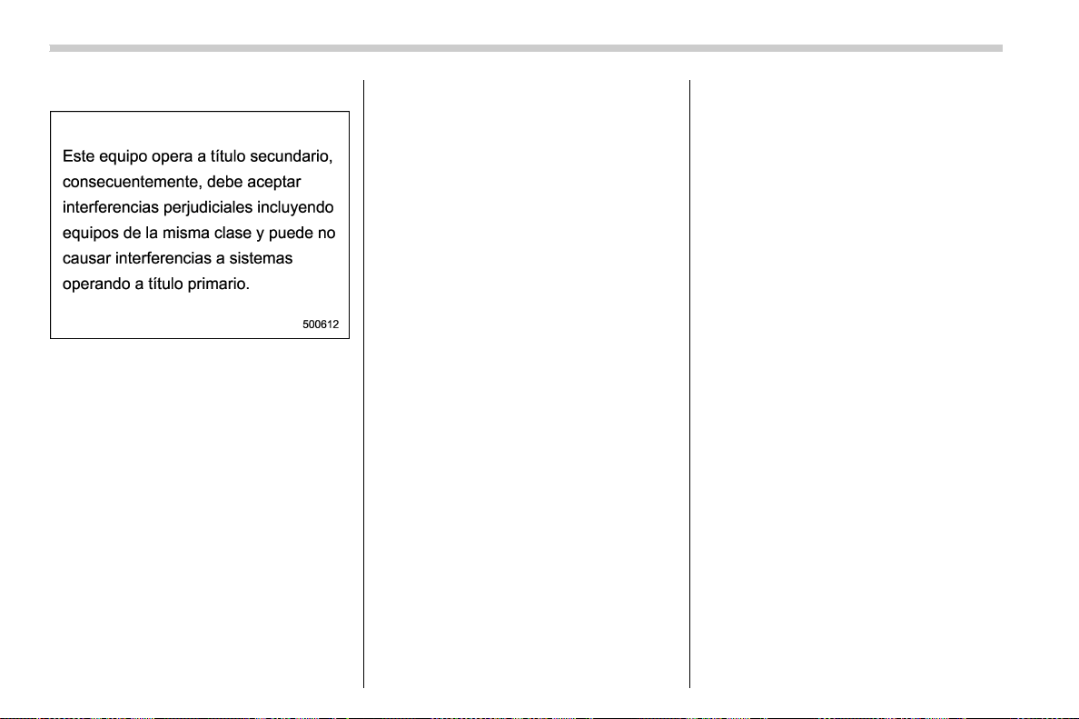
(124,1)
北米Model "A1700BE-B" EDITED: 2017/ 10/ 11
! Mexico-spec. models
& Alarm system
The alarm system helps to protect your
vehicle and valuables from theft. The horn
sounds and the hazard warning flashers
flash if someone attempts to break into
your vehicle.
For models with “keyless access with
push-button start system”:
You can arm or disarm the system with the
keyless access function or access key fob.
The system will not be activated when the
push-button ignition switch is in the “ACC”
or “ON” position.
For models without “keyless access
with push-button start system”:
You can arm or disarm the system with the
remote transmitter.
The system will not be activated when the
key is inserted into the ignition switch.
Your vehicle’s alarm system has been set
for activation at the time of shipment from
the factory. You can set the system for
deactivation yourself or have it done by
your SUBARU dealer.
! System operation
The alarm system will give the following
alarms when triggered.
. The vehicle’s horn will sound for 30
seconds.
. The hazard warning flashers will flash
for 30 seconds.
If any of the doors, trunk lid or engine hood
remains open after the 30-second period,
the horn will continue to sound for a
maximum of 3 minutes. If the door, trunk
lid or engine hood is closed while the horn
is sounding, the horn will stop sounding
with a delay of up to 30 seconds.
The alarm is triggered by:
. Opening any of the doors or the trunk lid
. Opening the engine hood.
. Physical impact to the vehicle, such as
forced entr y (only mod els wit h shock
sensors (dealer option))
NOTE
You can set the alarm system to trigger
the illumination of the following interior
lights.
. Map lights (for models with moon-
roof)
. Dome light (illuminates only when
the dome light switch is in the “DOOR”
position)
The notifications regarding the map
lights (for models with moonroof) and
dome light are deactivated as the
factory setting. A SUBARU dealer can
activate the syst em. Con tact your
SUBARU dealer for details.
! Activating and deactivating the
alarm system
To change the setting of your vehicle’s
alarm system for activation or deactiva-
tion, do the following.
1. Disarm the alarm system. Refer to
“Disarming the system” F2-28.
2. Sit in the driver’s seat and shut all
doors and the trunk lid.
3. Turn the ignition switch to the “ON”
position.
4. Hold down the REAR (UNLOCK) side
Keys and doors/Anti-theft system
2-24
(125,1)
北米Model "A1700BE-B" EDITED: 2017/ 10/ 11
of the driver’s power door locking switch,
open the driver ’s door within the following
1 second, and wait 10 seconds without
releasing the switch. The setting will then
be changed as follows.
If the system was previously activated:
The odometer/trip meter screen displays
“AL OF” and the horn sounds twice,
indicating that the system is now deacti-
vated.
If the system was previously deacti-
vated:
The odometer/trip meter screen displays
“AL ON” and the horn sounds once,
indicating that the system is now activated.
NOTE
You may have the above setting change
done by your SUBARU dealer.
! If you have accidentally triggered
the alarm system
! To stop the alarm
Perform any of the following operations.
. Press any button on the access key fob/
remote transmitter.
. Turn the ignition switch to the “ON”
position (models without “keyless access
with push-button start system”).
. Turn the push-button ignition to the
“ACC” position (mod els with “keyless
access with push-button start system”).
NOTE
Only registered keys will stop the
alarm. If the key is not registered, the
alarm will not stop.
! Arming the system
NOTE
. You can arm the system even if the
engine hood, the windows and/o r
moonroof are open. Always make sure
that they are fully closed before arming
the system.
. When arming the system, if any of
the doors or the trunk lid is not fully
closed, an electronic chirp sounds five
times, the hazard warning flashers
flash five times to alert you that the
doors (or the trunk lid) are not properly
closed. When you close the door, doors
will automatically lock and the system
will automatically arm in 30 seconds.
. The 30-second standby time can be
eliminated if you prefer. Have it per-
formed by your SUBARU dealer.
. If you open the trunk using the
remote transmit ter’s “
” but ton in
the surveillance state (or the standby
state), the system will be temporarily
placed in a standby state. The system
will go back to the surveillance state in
30 seconds upon locking the trunk.
. The system is in the standby state
for a 30-second period before arming
the system. The security indicator light
will flash at short intervals during this
period.
. If any of the following actions is
done during the standby period, the
system will not switch to the surveil-
lance state.
– Doors are unlocked using the
access key fob/remote transmitter.
– Doors are unlocked using the
keyless access function (models
with “key less access with push-
button start system”).
– Any door is opened.
– The ignition switch is turned to
the “ON” position (models without
“keyless access with push-button
start system”).
– Push-buttonignitionswitchis
turned to the “ACC” position (mod-
els with “keyless access with push-
button start system”).
– CONTINUED –
Keys and doors/Anti-theft system
2-25
2
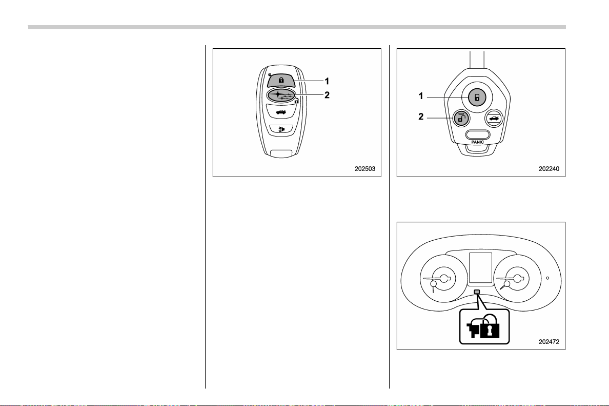
(126,1)
北米Model "A1700BE-B" EDITED: 2017/ 10/ 11
! To arm the system using the
access key fob/remote transmit-
ter
1. Close all windows and the moonroof (if
equipped).
2. Remove the key from the ignition
switch (models without “keyless access
with push-button start system”)/turn the
push-button ignition switch to the “OFF”
position (models with “keyless access with
push-button start system”).
3. Open the doors and get out of the
vehicle.
4. Make sure that the engine hood is
locked.
5. Close all doors and the trunk lid.
Access key fob
1) Arm button: Press to arm the system
2) Disarm button: Press to disarm the
system
Transmitter
1) Arm button: Press to arm the system
2) Disarm button: Press to disarm the
system
6. Briefly press the arm button (for less
than 2 seconds).
Keys and doors/Anti-theft system
2-26
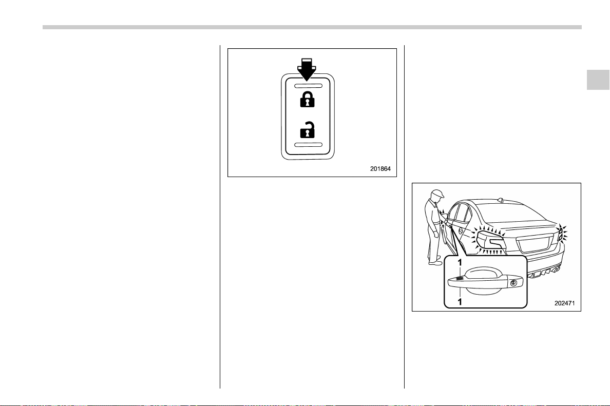
(127,1)
北米Model "A1700BE-B" EDITED: 2017/ 10/ 11
All doors will lock, an electronic chirp will
sound once, the hazard warning flashers
will flash once, and the security indicator
light will start flashing rapidly.
After rapid flashing for 30 seconds (stand-
by time), the indicator light will then flash
slowly (twice approximately every 2 sec-
onds), indicating that the system has been
armed for surveillance.
! To arm the system using power
door locking switches
1. Close all windows.
2. Remove the key from the ignition
switch (models without “keyless access
with push-button start system”)/turn the
push-button ignition switch to the “OFF”
position (models with “keyless access with
push-button start system”).
3. Open the doors and get out of the
vehicle.
4. Make sure that the engine hood is
locked.
5. Close the doors and the trunk lid but
leave only the driver’s door or the front
passenger’s door open.
6. Press the front side (“LOCK ” side) of
the power door locking switch to set the
door locks.
7. Close the door.
An electronic chirp will sound once, the
hazard warning flashers will flash once
and the security indicator light will start
flashing rapidly.
After rapid flashing for 30 seconds (stand-
by time), the indicator light will then flash
slowly (twice approximately every 2 sec-
onds), indicating that the system has been
armed for surveillance.
! To arm the system using the
keyless access function (if
equipped)
1. Close all windows and the moonroof (if
equipped)
2. Turn the push-button ignition switch to
the “OFF” position.
3. Open the doors and get out of the
vehicle.
4. Make sure that the engine hood is
locked.
5. Close all doors and the trunk lid.
1) Door lock sensor
– CONTINUED –
Keys and doors/Anti-theft system
2-27
2
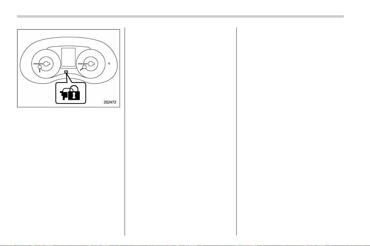
(128,1)
北米Model "A1700BE-B" EDITED: 2017/ 10/ 11
Security indicator light
6. Carry the access key fob and touch the
door lock sensor.
All doors will lock, an electronic chirp will
sound once, the hazard warning flashers
will flash once, and the security indicator
light will start flashing rapidly.
After rapid flashing for 30 seconds (stand-
by time), the security indicator light will
then flash slowly (twice a pproximately
every 2 seconds), indicating tha t the
system has been armed for surveillance.
! Disarming the system
Perform either of the following procedures.
. Briefly press the disarm button (for less
than 2 seconds) on the access key fob/
remote transmitter.
. Carry the access key fob and grip the
front door handle (models with “keyless
access with push-button start system”).
The flashing of the security indicator light
will then change slowly (once approxi-
mately every 3 seconds from twice ap-
proximately every 2 seconds), indicating
that the alarm system has been disarmed.
! Emergency disarming
If you cannot disarm the system using the
access key fob/transmitter (i.e. the trans-
mitter is lost, broken or the transmitter
battery is too weak), you can disarm the
system without using the access key fob/
remote transmitter.
You can disarm the system if you turn the
ignition switch from the “LOCK”/“OFF” to
the “ON” position with a registered key/
access key fob.
NOTE
For models with “keyless access with
push-button start system”, if the bat-
tery of the access key fob is dis-
charged, perform the procedure de-
scribed in “Switching power status”
F9-26. In such a case, replace the
battery immediately. Refer to “Repla-
cing battery of access key fob” F11-52.
! Valet mode
When you choose the valet mode, the
alarm system does not operate. In valet
mode, the access key fob/transmitter is
used only for locking and unlocking the
doors and for panic activation.
To enter t he valet mode, change the
setting of your vehicle’s alarm system for
deactivation mode. Refer to “Activating
and deactivating the alarm system” F2-
24. The security indicator light will continue
to flash once every 3 seconds indicating
that the system is in the valet mode.
To exit valet mode, change the setting of
your vehicle’s alarm system for activation
mode. Refer to “Activating and deactivat-
ing the alarm system” F2-24.
Keys and doors/Anti-theft system
2-28
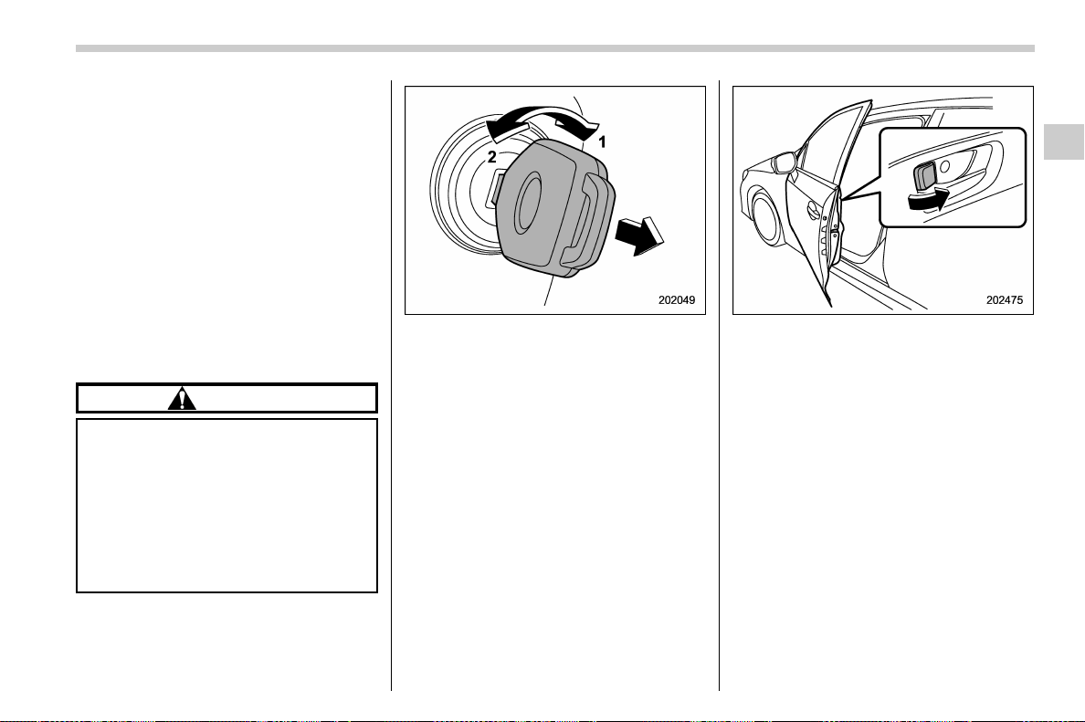
(129,1)
北米Model "A1700BE-B" EDITED: 2017/ 10/ 11
! Passive arming (models without
“keyless access with push-button
start system”)
When passive arming mode has been
programmed by the dealer, arming of the
system is automa tically acco mplishe d
without using the remote transmitter. Note
that in this mode, DOORS MUST BE
MANUALLY LOCKED.
! To enter the passive mode
If you wish to program the passive arming
mode, have it done by your SUBARU
dealer.
! Arming the system
CAUTION
In passive mode, the system will
automatically activate the alarm but
WILL NOT automatically lock the
doors. In order to lock the doors
you must either lock them as indi-
cated in step 4 below or with the key
once they have been closed. Failure
to lock the doors manually will result
in a higher security risk.
1. Turn the ignition switch to the “ON”
position.
1) ON
2) LOCK
2. Turn the ignition switch from “ON” to
“LOCK” position and remove the key from
the ignition switch.
3. Open the doors and get out of the
vehicle.
4. Before closing the doors, lock all doors
with the inside door lock levers.
5. C lose the doors. The system will
automatically arm after 1 minute.
In the passive mode, you can also arm the
system with the remote transmitter or with
the power door locking switches. If you use
the remote transmitter or power door
locking switch to lock the vehicle, arming
will take place immediately regardless of
whether or not the passive mode has been
selected.
! Disarming the system
To disarm the system, briefly press the
disarm button on the remote transmitter.
– CONTINUED –
Keys and doors/Anti-theft system
2-29
2

(130,1)
北米Model "A1700BE-B" EDITED: 2017/ 10/ 11
! Tripped sensor identification
The security indicator light flashes when
the alarm system has been triggered. Also,
the number of flashes indicates the loca-
tion of unauthorized intrusion or the
severity of impact on the vehicle.
After turning the ignition switch to the “ON”
position, the indicator light will light for 1
second and then flash as follows.
. When a door was opened: 5 times
. When the trunk was opened: 4 times
. When the engine hood was opened: 3
times
. When a strong impact or multiple
impacts were sensed: twice (only models
with shock sensors (dealer option))
. When a light impact was sensed: once
(only models with shock sensors (dealer
option))
NOTE
Any of the above indicator light flash-
ings will recur each time the ignition
switch is turned to the “ON” position.
Rearming the alarm system cancels the
flashing.
! Shock sensors (dealer option)
The shock sensors trigger the alarm
system when they sense impacts applied
to the vehicle and when any of their electric
wires are cut. The alarm system causes
the horn to sound and the hazard warning
flashers to flash for a short time when the
sensed impact is weak, but it warns of a
strong impact or multiple impacts by
sounding the horn and flashing the hazard
warning flashers, both lasting approxi-
mately 30 seconds.
If you desire, your SUBARU dealer can
connect them and set them for activation
or deactivation.
NOTE
. The shock sensors are not always
able to sense impacts caused by break-
ing in, and cannot sense an impact that
does not cause vibration (such as
breaking the glass using a rescue
hammer).
. The shock sensors may sense vibra-
tion as indicated in the following ex-
amples and trigger the alarm system.
Select the settings of the alarm system
and shock sensors appropriately de-
pending on where you usually park
your vehicle.
Examples:
– Vibration from a construction site
– Vibration in a multistory car park
– Vibration from trains
. You can have the sensitivity of the
shock sensors adjusted to your pre-
ference by your SUBARU dealer.
Keys and doors/Anti-theft system
2-30
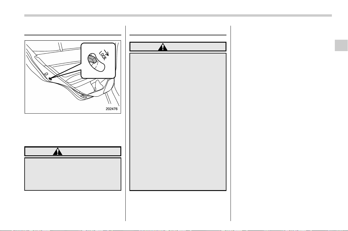
(131,1)
北米Model "A1700BE-B" EDITED: 2017/ 10/ 11
Child safety locks
Each rear door has a child safety lock.
When the child safety lock lever is in the
lock position, the door cannot be opened
from inside. The door can only be opened
from the outside.
WARNING
Always turn the child safety locks to
the “LOCK” position when children
sit in the rear seat. Serious injury
could result if a child accidentally
opens the door and falls out.
Windows
WARNING
To avoid serious personal injury
caused by accidental, child’s mis-
chief, or impr oper operation, the
driver is responsible for obeying
the following instructions without
exception.
. When operating the power win-
dows, be extremely careful to
prevent anyone’s fingers, arms,
neck, head or other objects from
being caught in the window.
. Always lock the passengers’ win-
dows using the lock switch when
children are riding in the vehicle.
. Always carry the key when you
leave the vehicle for safety rea-
sons and never allow an unat-
tended child to remain in the
vehicle. Failure to follow this
procedure could result in injury
to a child operating the power
window.
The power windows operate only when the
ignition switch is in the “ON” position.
NOTE
If the vehicle battery is disconnected (e.
g., the battery or fuse is replaced), the
following functions will be deactivated.
. One-touch auto up/down function
. Anti-entrapment function
Initialize the power window to reacti-
vate such functions. For details, refer to
“Initialization of power window” F2-35.
– CONTINUED –
Keys and doors/Child safety locks
2-31
2
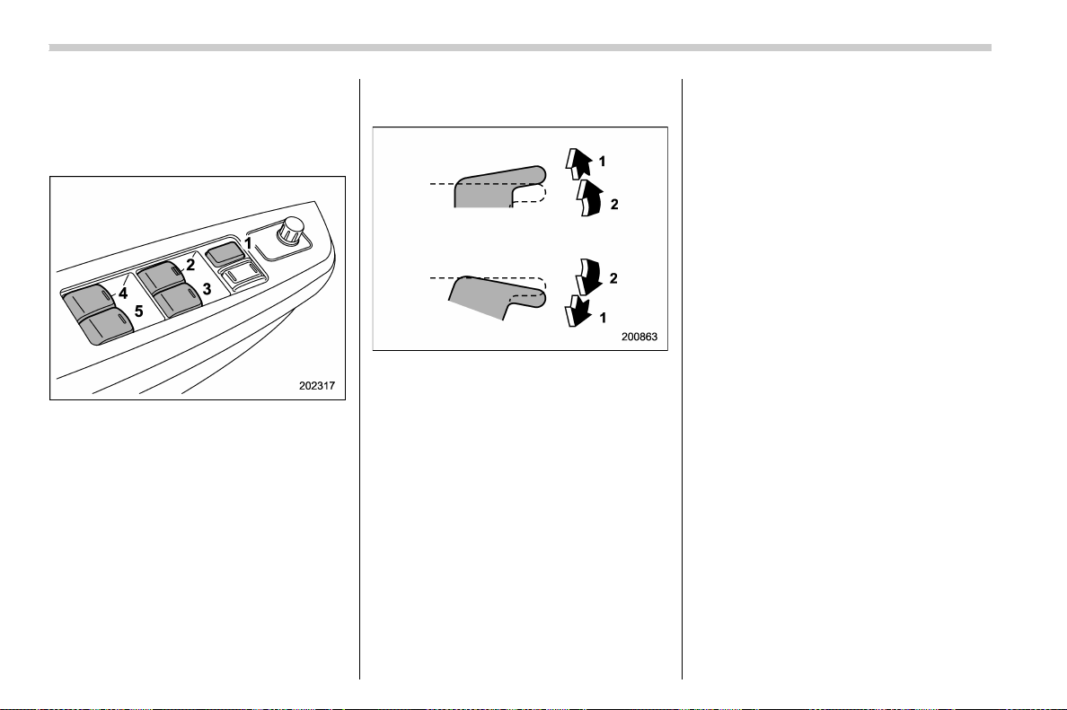
(132,1)
北米Model "A1700BE-B" EDITED: 2017/ 10/ 11
& Power window operation by
driver
! Driver’s side power window
switches
1) Lock switch
2) For driver’s window (with one-touch auto
up and down feature)
3) For front passenger’s window (with one-
touch auto up and down feature)
4) For rear left window
5) For rear right window
You can control all the door windows by the
power window switch cluster at the driver
side door.
! Operating the driver’s/front pas-
senger’s window
1) Automatically open/close
2) Open/close
To open:
Press the switch down lightly and hold it.
The window will open as long as the switch
is held.
Press the switch down until it clicks and
release it, and the window will fully open.
To stop the window halfway, pull the switch
up lightly.
To close:
Pull the switch up lightly and hold it. The
window will close as long as the switch is
held.
Pull the switch up until it clicks and release
it, and the window will fully close. To stop
the window halfway, press the switch down
lightly.
NOTE
When the following op erations are
performed, the power window breaker
will operate and it may not be possible
to open or close the window.
. After the driver’s or front passen-
ger’s window is fully closed or fully
opened, the switch is continuously
operated in the same direction for a
few seconds.
. After the windows for three or more
seats are fully closed or fully opened,
each switch is continuously operated
in the same direction simultaneously
for a few seconds.
In this case, after the breaker recovers,
be sure to initialize the power windows.
If they are not initialized, the one-touch
auto up/down function will not operate.
Refer to “Initialization of power win-
dow” F2-35.
Keys and doors/Windows
2-32
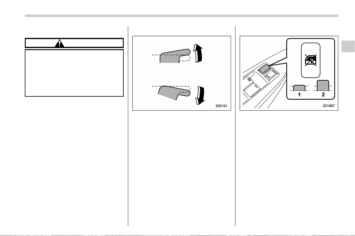
(133,1)
北米Model "A1700BE-B" EDITED: 2017/ 10/ 11
! Anti-entrapment function
CAUTION
. Never attempt to test this func-
tion using fingers, hands or other
parts of your body.
. The anti-en trapment funct ion
may not operate properly if some
object gets trapped just before
the window fully closes.
NOTE
. If a window detects an impact similar
to that caused by trapping an object (for
example, when the vehicle encounters
a deep pothole), the anti-entrapment
function may operate.
. The window cannot be operated for a
few seconds after the anti-entrapment
function operates.
While closing the driver ’s or front passen-
ger’s window automatically, if the window
senses a substantial enough object
trapped between the window and the
window frame, it automatically moves
down slightly and stops.
! Operating the rear windows
To open:
Press the appropriate switch down and
hold it until the window reaches the desired
position.
To close:
Pull the switch up and hold it until the
window reaches the desired position.
! Locking the passengers’ windows
1) Lock
2) Unlock
To lock:
Press the lock switch. When the lock
switch is in the lock position, the passen-
gers’ windows cannot be opened or
closed.
To unlock:
Press the lock switch again.
– CONTINUED –
Keys and doors/Windows
2-33
2
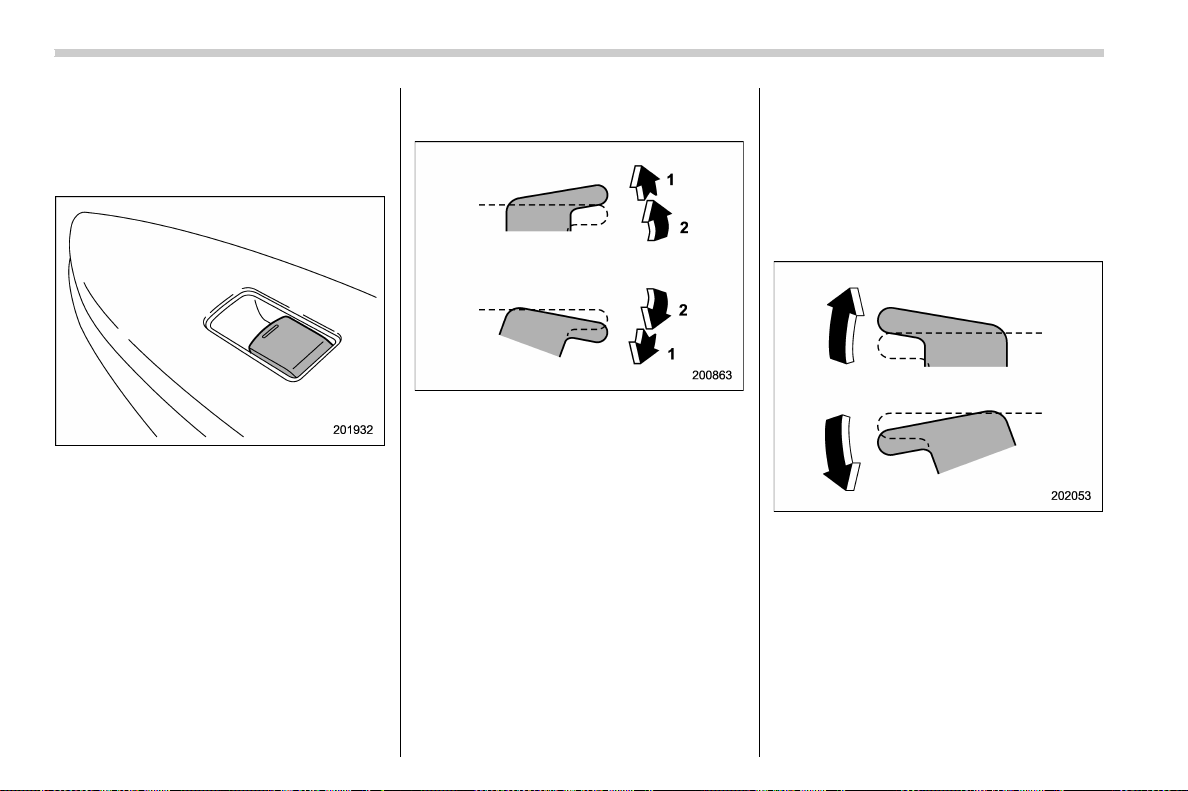
(134,1)
北米Model "A1700BE-B" EDITED: 2017/ 10/ 11
& Power window operation by
passengers
! Passenger’s side power window
switches
Each passenger window can be controlled
by the power window switch located on the
door.
! Operating the front passenger’s
window
1) Automatically open/close
2) Open/close
To open:
Press the switch down lightly and hold it.
The window will open as long as the switch
is held.
Press the switch down until it clicks and
release it, and the window will fully open.
To stop the window halfway, pull the switch
up lightly.
To close:
Pull the switch up lightly and hold it. The
window will close as long as the switch is
held.
Pull the switch up until it clicks and release
it, and the window will fully close. To stop
the window halfway, press the switch down
lightly.
! Anti-entrapment function
Refer to “Anti-entrapment function” F2-
33.
! Operating the rear passenger’s
windows
To open:
Press the switch down and hold it until the
window reaches the desired position.
To close:
Pull the switch up and hold it until the
window reaches the desired position.
When the lock switch on the power window
switch cluster, located on the driver’s side
door, is in the lock position, the passen-
gers’ windows cannot be operated with the
Keys and doors/Windows
2-34
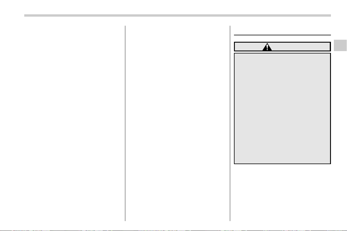
(135,1)
北米Model "A1700BE-B" EDITED: 2017/ 10/ 11
passengers’ switches.
& Off delay function
You can operate the front windows for
approximately 42 seconds even after turn-
ing the ignition switch from the “ON”
position to the “ACC ” or “OFF” position. If
a front door is opened within 42 seconds,
the off delay function is canceled.
& Initialization of power window
If the vehicle’s battery is disconnected due
to situations such as battery or fuse
replacement, the following functions will
be deactivated.
. One-touch auto up/down function
. Anti-entrapment function
Initialize the driver’s and front passenger’s
power window using the following proce-
dure to reactivate these functions.
1. Close the door.
2. Turn the ignition switch to the “ON”
position.
3. Open the window halfway by pressing
down the power window switch.
4. Pull up the power window switch and
close the window completely. Continue
pulling up the switch for approximately 1
second after the window is closed com-
pletely.
5. Open the window completely by fully
pressing down the power windows switch.
It is necessary to repeat the same initi-
alization procedure for both driver’s and
front passenger’s window switches.
Trunk lid
WARNING
. To prevent dangerous exhaust
gas from entering the vehicle,
always keep the trunk lid closed
while driving.
. Help prevent children, adults or
animals from locking themselves
in the trunk. On hot or sunny
days, the temperature in the trunk
could quickly become high en-
ough to cause death or serious
heat-related injuries including
brain damage to anyone locked
inside, particularly for small chil-
dren.
. When leaving the vehicle, close
all windows and lock all doors.
Also make certain that the trunk
is closed.
– CONTINUED –
Keys and doors/Trunk lid
2-35
2

(136,1)
北米Model "A1700BE-B" EDITED: 2017/ 10/ 11
CAUTION
TYPE RA:
. Make sure to press the trunk lid
lightly on its outer surface.
. Do not hold or push the rear wing
when closing the trunk lid.
& To open and close the trunk
lid from outside
To open the trunk lid from outside, use the
keyless access function or remote keyless
entry system. For details, refer to the
following section.
. For models with “keyless access with
push-button start system”, refer to “Open-
ing trunk” F2-11.
. For models without “keyless access
with push-button start system”, refer to
“Opening the trunk lid” F2-20.
To close the trunk lid, lightly press the trunk
lid down until the latch engages.
NOTE
. Do not leave your valuables in the
trunk when you leave your vehicle.
. You can disable the “
” button on
the access key fob/transmitter. Contact
your SUBARU dealer to change the
setting.
& To open the trunk lid from
inside
Trunk opener switch
Press the trunk opener switch for more
than 1 second.
NOTE
The trunk lid will not open when the
select lever is in a position other than
the “P” position (CVT models) or the
vehicle is moving.
& Internal trunk lid release
handle
The internal trunk lid release handle is a
device designed to open the trunk lid from
inside the trunk. In the event children or
adults become locked inside the trunk, the
handle allows them to open the lid. The
handle is located on the inside of the trunk
lid.
To open the trunk lid from inside the trunk,
pull the yellow handle as indicated by the
arrow on the handle. This operation
unlocks the trunk lid. Then, push up the lid.
The handle is made of material that
remains luminescent for approximately
an hour in the dark trunk space after it is
Keys and doors/Trunk lid
2-36
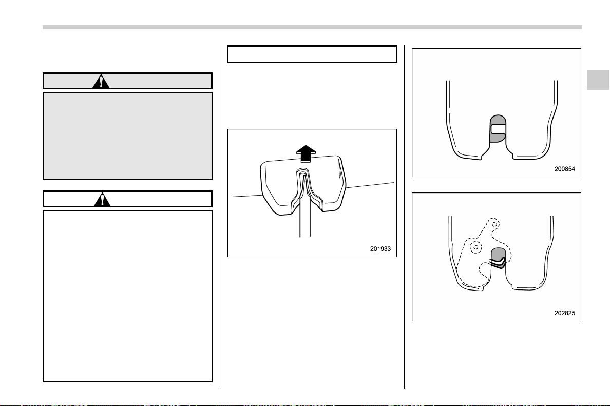
(137,1)
北米Model "A1700BE-B" EDITED: 2017/ 10/ 11
exposed to ambient light even for a short
time.
WARNING
Never allow any child to get in the
trunk and play with the release
handle. If the driver starts the vehi-
cle without knowing that a child is
inside the trunk and the child opens
the lid using the release handle, the
child could fall out and be killed or
seriously injured.
CAUTION
. Do not close the lid while gripping
the release handle. The handle
may be damaged.
. Do not use the handle as a hook
to fasten straps or ropes to
secure your cargo in the trunk.
Such use may result in damage of
the handle.
. Load the trunk so that cargo
cannot strike the release handle.
If the cargo hits the handle while
the vehicle is being driven, the
handle may be pulled and the
trunk lid may open. That may
cause cargo to fall out of the
trunk, which could create a traffic
safety hazard.
! Inspection
Perform the following steps at least twice a
year to check the release handle for
correct operation.
1. Open the trunk lid.
2. Use a flat-head screwdriver with a thin
blade. Slide the flat-head screwdriver
blade from the slit aperture of the lock
assembly fully to the end until you hear a
click.
This places the latch in the locked position.
3. Move the release handle, from outside
the vehicle, in the direction of the arrow to
check if the latch is released.
If the latch is not released, contact your
– CONTINUED –
Keys and doors/Trunk lid
2-37
2
(138,1)
北米Model "A1700BE-B" EDITED: 2017/ 10/ 11
SUBARU dealer.
In that case, use the key to release the
latch, then close the trunk lid.
Also, if the movement of the release
handle feels restricted or not entirely
smooth during operation, or the handle
and/or handle base is cracked, contact
your SUBARU dealer.
Moonroof (if equipped)
WARNING
Never let anyone’s hands, arms,
head or any objects protrude from
the moonroof. A person could be
seriously injured if the vehicle stops
suddenly or turns sharply or if the
vehicle is involved in an accident.
To avoid serious personal injury
caused by accidental, child’s mis-
chief, or impr oper operation, the
driver is responsible for obeying
the following instructions without
exception.
. Before closing the moonroof,
make sure that no one’s hands,
arms, head or other objects will
be accidentally caught in the
moonroof.
. Always carry the key when you
leave the vehicle for safety rea-
sons and never allow an unat-
tended child to remain in the
vehicle. Failure to follow this
procedure could result in injury
to a child operating the moon-
roof.
. Never try to check the anti-en-
trapment function by deliberately
placing part of your body in the
moonroof.
CAUTION
. Do not sit on the edge of the open
moonroof.
. Do not operate the moonroof if
falling snow or extremely cold
conditions have caused it to
freeze shut.
. The anti-entrapment function
does not operate when the moon-
roof is being tilted down. Be sure
to confirm that it is safe to do so
before tilting the moonroof down.
. If the moonroof does not close,
we recommend that you have the
system checked by a SUBARU
dealer.
The moonroof has both tilting and sliding
functions.
The moonroof operates only when the
ignition switch is in the “ON” position.
Keys and doors/Moonroof
2-38

(139,1)
北米Model "A1700BE-B" EDITED: 2017/ 10/ 11
& Moonroof switches
! Tilting moonroof
1) Raise
2) Lower
The tilting function is activated only when
the moonroof is fully closed.
To raise:
Press and hold the rear side of the “UP/
DOWN” switch for a short time. The
moonroof raises completely.
To lower:
Press and hold the front side of the “UP/
DOWN” switch until the preferred position
has reached.
Release the switch after the moonroof has
been raised or has been lowered comple-
tely. Pressing the switch continuously may
cause damage to the moonroof.
NOTE
One-touch operation does not take
place when the moonroof is lowered.
Press the switch continuously to lower
the moonroof.
! Sliding moonroof
1) Open
2) Close
Tilt down the moonroof completely before
performing the sliding operation.
To open:
Press the rear side of the “OPEN/CLOSE”
switch. The sun shade will also be opened
together with the moonroof. The moonroof
will stop once at a midway position. Press
the rear side of the switch again to open
the moonroof completely.
To close:
Press the front side of the “OPEN/CLOSE”
switch.
To stop the moonroof at a selected mid-
way position while opening or closing it,
momentar ily push the switch to the
“OPEN” side or “CLOSE ” side.
After washing the vehicle or after it rains,
wipe away water on the roof prior to
opening the moonroof to prevent drops of
water from falling into the passenger
compartment.
NOTE
Driving with the moonroof fully open
can cause an annoying sound to be
generated at high speeds. If this oc-
curs, use the moonroof at the midway
stop position when the moonroof is
opened.
– CONTINUED –
Keys and doors/Moonroof
2-39
2
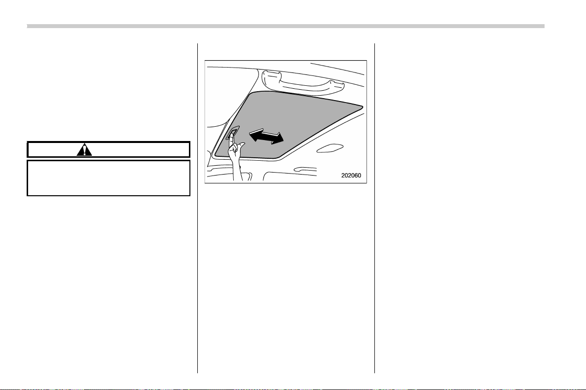
(140,1)
北米Model "A1700BE-B" EDITED: 2017/ 10/ 11
! Anti-entrapment function
When the moonroof senses a substantial
enough object trapped between its glass
and the vehicle’s roof during closure, it
automatically moves back to the fully open
position and stops there. The anti-entrap-
ment function may also be activated by a
strong shock on the moonroof even when
there is nothing trapped.
CAUTION
Never attempt to test this function
using fingers, hands or other parts
of your body.
NOTE
For the sake of safety, it is recom-
mended that you avoid driving with the
moonroof fully opened.
& Sun shade
You can slide the sun shade forward or
backward by hand while the moonroof is
closed.
If the moonroof is opened, the sun shade
also moves back.
Keys and doors/Moonroof
2-40

(143,1)
北米Model "A1700BE-B" EDITED: 2017/ 10/ 11
Ignition switch......................................................... 3-4
Conventional type ignition switch........................... 3-5
Push-button ignition switch.................................... 3-6
Hazard warning flasher .......................................... 3-8
Meters and gauges ................................................. 3-8
Combination meter illumination.............................. 3-8
Canceling the function for meter/gauge needle
movement upon turning on the ignition switch..... 3-9
Speedometer ......................................................... 3-9
Odometer............................................................... 3-9
Double trip meter ................................................... 3-9
Tachometer ........................................................... 3-10
Fuel gauge............................................................ 3-10
Temperature gauge ............................................... 3-11
ECO gauge ...........................................................3-12
REV indicator light and buzzer (STI) ................... 3-12
Warning and indicator lights................................ 3-13
Seatbelt warning light and chime ..........................3-14
SRS airbag system warning light........................... 3-15
Front passenger’s frontal airbag ON and OFF
indicators ...........................................................3-16
CHECK ENGINE warning light/Malfunction
indicator light .....................................................3-16
Charge warning light............................................. 3-17
Oil pressure warning light ..................................... 3-17
Engine low oil level warning indicator
(except STI) ........................................................3-17
Windshield washer fluid warning indicator ............3-18
AT OIL TEMP warning light (CVT models) .............. 3-18
Rear differential oil temperature warning light
(STI) ...................................................................3-18
Low tire pressure warning light
(U.S.-spec. models)............................................3-19
ABS warning light.................................................3-20
Brake system warning light...................................3-21
Electronic parking brake indicator light (models
with electronic parking brake system) ................3-23
Low fuel warning light .......................................... 3-24
Hill start assist warning light/Hill start assist OFF
indicator light (models without electronic
parking brake system) .......................................3-24
Auto Vehicle Hold ON indicator light (models with
electronic parking brake system) ....................... 3-24
Auto Vehicle Hold operation indicator light
(models with electronic parking brake system)... 3-24
Door open warning light .......................................3-25
All-Wheel Drive warning light (if equipped).. .......... 3-25
Power steering warning light (except STI) ............. 3-25
LED headlight warning light (if equipped)..............3-25
Vehicle Dynamics Control warning light/Vehicle
Dynamics Control operation indicator light ........3-26
Vehicle Dynamics Control OFF indicator
light/Traction mode indicator light......................3-27
Warning chimes and warning indicator of the
keyless access with push-button start system
(if equipped) ...................................................... 3-28
Security indicator light..........................................3-33
SI-DRIVE indicator (if equipped) ............................3-34
Gear position indicator (MT models)/Shift-up
indicator (STI).................................................... 3-34
Select lever/gear position indicator
(CVT models).....................................................
3-34
Turn signal indicator lights ...................................3-35
High beam indicator light...................................... 3-35
Instruments and controls
3

(144,1)
北米Model "A1700BE-B" EDITED: 2017/ 10/ 11
High Beam Assist indicator light (green)
(if equipped) ....................................................... 3-35
High Beam Assist warning indicator (yellow)
(if equipped) ....................................................... 3-35
Cruise control indicator ........................................3-35
Cruise control set indicator ...................................3-35
Automatic headlight beam leveler warning light
(models with LED headlights).............................. 3-35
Front fog light indicator light (if equipped) ............3-35
Headlight indicator light ........................................ 3-35
Driver’s control center differential auto indicator
(STI) ...................................................................3-36
Driver’s control center differential indicator and
warning (STI) ......................................................3-36
REV indicator light (STI)........................................3-37
Steering Responsive Headlight warning indicator/
Steering Responsive Headlight OFF indicator
(if equipped) ....................................................... 3-37
BSD/RCTA warning indicator (if equipped)............. 3-37
BSD/RCTA OFF indicator (if equipped) .................. 3-37
RAB warning indicator (if equipped) ...................... 3-37
RAB OFF indicator light (if equipped) ....................3-37
Combination meter display (color LCD) ............. 3-38
Basic operation.....................................................3-39
Welcome screen (opening animation) and
Good-bye screen (ending animation) ...................3-39
Warning screen..................................................... 3-39
Basic screens ....................................................... 3-40
Warning indication ................................................3-41
Menu screens .......................................................3-41
Multi-function display (color LCD) ...................... 3-44
Welcome screen ...................................................3-45
Self-check screen ................................................. 3-45
Interruption screen ...............................................3-46
Basic operation ....................................................3-46
Basic screens.......................................................3-47
Setting screen ...................................................... 3-52
How to get the source code using the open
source...............................................................3-63
Light control switch ............................................. 3-63
Headlights ............................................................3-64
High/low beam change (dimmer) ........................... 3-65
Headlight flasher .................................................. 3-68
Daytime running light system ............................... 3-69
Steering Responsive Headlight (SRH)
(if equipped) ....................................................... 3-69
To turn on/off the SRH ..........................................3-69
Turn signal lever ................................................... 3-70
One-touch lane changer........................................ 3-70
Illumination brightness control ........................... 3-71
Automatic dimming function .................................3-71
Auto dimmer cancel function ................................3-71
Headlight beam leveler (if equipped) .................. 3-71
Automatic headlight beam leveler
(models with LED headlights) ............................3-71
Fog light switch (if equipped).............................. 3-72
Wiper and washer................................................. 3-72
Windshield wiper and washer switches ................. 3-74
Instruments and controls

(145,1)
北米Model "A1700BE-B" EDITED: 2017/ 10/ 11
Mirrors ................................................................... 3-75
Inside mirror .........................................................3-75
Auto-dimming mirror/compass (if equipped) .......... 3-75
Auto-dimming mirror/compass with HomeLink
®
(if equipped) ....................................................... 3-76
Outside mirrors ....................................................3-83
Defogger and deicer............................................. 3-84
Tilt/telescopic steering wheel .............................. 3-85
Horn ....................................................................... 3-86
Instruments and controls
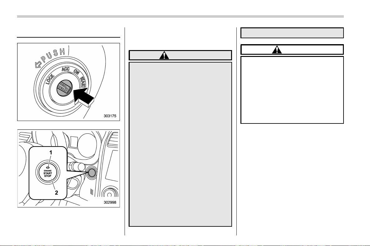
(146,1)
北米Model "A1700BE-B" EDITED: 2017/ 10/ 11
Ignition switch
Conventional type ignition switch
Push-button ignition switch
1) Operation indicator
2) Push-button ignition switch
The design of the push-button ignition
switch may be slightly different depending
on the models.
WARNING
. Before leaving the vehicle, ob-
serve the following instructions
for safety.
– Remove the key from the igni-
tion switch (models with con-
ventional type ignition
switch).
– Carry out the access key fob
(models with push-button
ignition switch).
– Never allow an unattended
child to remain in the vehicle.
Failure to observe these instruc-
tions could result in injury to a
child or others. Children could
operate the power windows, the
moonroof or other controls, or
even make the vehicle move.
. Never turn the ignition switch to
the “LOCK”/“OFF” position while
driving or being towed. Doing so
will lock the steering wheel, pre-
venting steering control. In addi-
tion, when the engine stops, it
takes a much greater effort than
usual to steer.
CAUTION
. To prevent the vehicl e battery
from discharging, keep the igni-
tion switch in the “LOCK”/“OFF ”
position when the engine is not
running.
. Do not use electrical accessories
for a long time with the ignition
switch in the “ON” or “ACC”
position. Doing so can cause the
battery to go dead.
Instruments and controls/Ignition switch
3-4
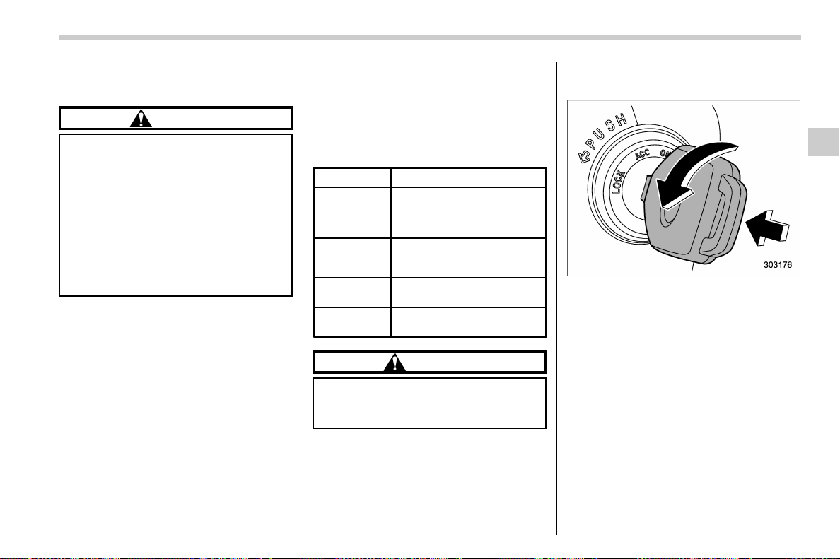
(147,1)
北米Model "A1700BE-B" EDITED: 2017/ 10/ 11
& Conventional type ignition
switch
CAUTION
Do not attach a large key holder or
key case to either key. If it hits your
knees or hands while driving, it
could turn the ignition switch to the
“ACC” or “LOCK” position, stop-
ping the engine. Also, if the key is
attached to a keyholder or to a large
bunch of other keys, centrifugal
force may act on it as the vehicle
moves, resulting in unwanted turn-
ing of the ignition switch.
NOTE
If the key cannot be turned, turn the
steering wheel slightly to the left and
right as you turn the ignition switch.
! Switch positions
Position Description
LOCK
You can insert or remove the
key only in this position. The
steering wheel will be locked
with the key removed.
ACC
You can use the electrical
accessories (audio, acces-
sory power outlet, etc.).
ON
Normal operating position
after starting the engine
START
The engine is started in this
position.
CAUTION
Do not turn the ignition switch to the
“START” position while the engine
is running.
NOTE
. To turn the key from the “ACC” to
“LOCK” position:
– Place the select lever in the “P”
position (CVT models).
– Push in and turn the key.
. If your registered key fails to start
the engine, perform the following pro-
cedure to restart the engine.
(1) Pull out the key once (the secur-
ity indicator light will blink).
(2) Insert the key again.
(3) Return the ignition switch to the
“START” position.
– CONTINUED –
Instruments and controls/Ignition switch
3-5
3
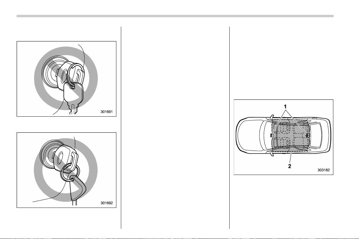
(148,1)
北米Model "A1700BE-B" EDITED: 2017/ 10/ 11
. The engine may not start in the
following cases:
– The key grip is touching another
key or a metallic key holder.
– The key is near another key that
contains an immobilizer transpon-
der.
– The key is near or touchin g
another transmitter.
! Key reminder chime
The reminder chime sounds when opening
the driver’s door with the ignition switch in
the “LOCK” or “ACC” position.
The chime stops after the following opera-
tion.
. turning the ignition switch to the “ON”
position
. removing the key from the ignition
switch
. closing the driver’s door
! Ignition switch light
For easy access to the ignition switch in
the dark, the ignition switch light illumi-
nates after the following operation.
. opening the driver’s door
. unlocking the driver ’s door using the
remote keyless entry transmitter.
The light remains illuminated for several
tens of seconds and then gradually turns
off after the following operation.
. closing the driver’s door
. unlocking the doors using the remote
keyless entry transmitter
The light turns off immediately after the
following operation.
. turning the ignition switch to the “ON”
position
. locking all doors using the remote
keyless entry transmitter
& Push-button ignition switch
! Safety precautions
Refer to “Safety precautions” F2-8.
! Operating range
1) Antenna
2) Operating range
Instruments and controls/Ignition switch
3-6
(149,1)
北米Model "A1700BE-B" EDITED: 2017/ 10/ 11
NOTE
. If the access key fob is not detected
within the operating range, you cannot
operate the push-button ignition switch
or start the engine.
. Even when the access key fob is
outside the vehicle, if it is placed too
close to the glass, it may be possible to
switch the power or to start the engine.
. Do not leave the access key fob in
the following places. It may become
impossible to operate the push-button
ignition switch or start the engine.
– On the instrument panel
– On the floor
– Inside the glove box
– Inside the door trim pocket
– On the rear seat
– On the rear shelf
– Inside the trunk
. If the battery of the access key fob is
discharged, perform the procedure de-
scribed in “Access key fob – if access
key fob does not operate properly” F9-
26 to operate the push-button ignition
switch or start the engine. In such a
case, replace the battery immediately.
Refer to “Replacing battery of access
key fob” F11-52.
! Switching power status
Power
status
Indicator color Operation
OFF OFF
Power is turned
off.
ACC Orange
You can use the
audio and ac-
cessory power
outlet.
ON
Orange (while
the engine is
stopped)
You can use all
electrical sys-
tems.
OFF (during en-
gine operation)
The power will be switched every time you
press the push-button ignition switch.
1. Carry the access key fob, and sit in the
driver’s seat.
2. Shift the shift lever in neutral (MT
models) or the select lever in the “P”
position (CVT models).
3. Press the push-button ignition switch
without depressing the clutch pedal (MT
models) or the brake pedal (CVT models).
The power will be switched in the se-
quence of “OFF”, “ACC”, “ON” and “OFF”.
When the engine is stopped and the push-
button ignition switch is in “ACC” or “ON”,
the operation indicator on the push-button
ignition switch illuminates in orange.
CAUTION
. To avoid a malfunction, observe
the following precautions.
– Do not spill drinks or other
liquids on the push-button
ignition switch.
– Do not touch the push-button
ignition switch with a hand
that is soiled with oil or other
contaminants.
. If the push-button ignition switch
does not operate smoothly, stop
the operation. Contact a SUBARU
dealer immediately.
. If the push-button ignition switch
does not illuminate even when
the instrument panel illumination
is on, have the vehicle inspected
at a SUBARU dealer.
. If the v ehicle was exposed to
sunlight for a long time, the sur-
face of the push-button ignition
switch may get hot. Be careful
not to burn yourself.
– CONTINUED –
Instruments and controls/Ignition switch
3-7
3
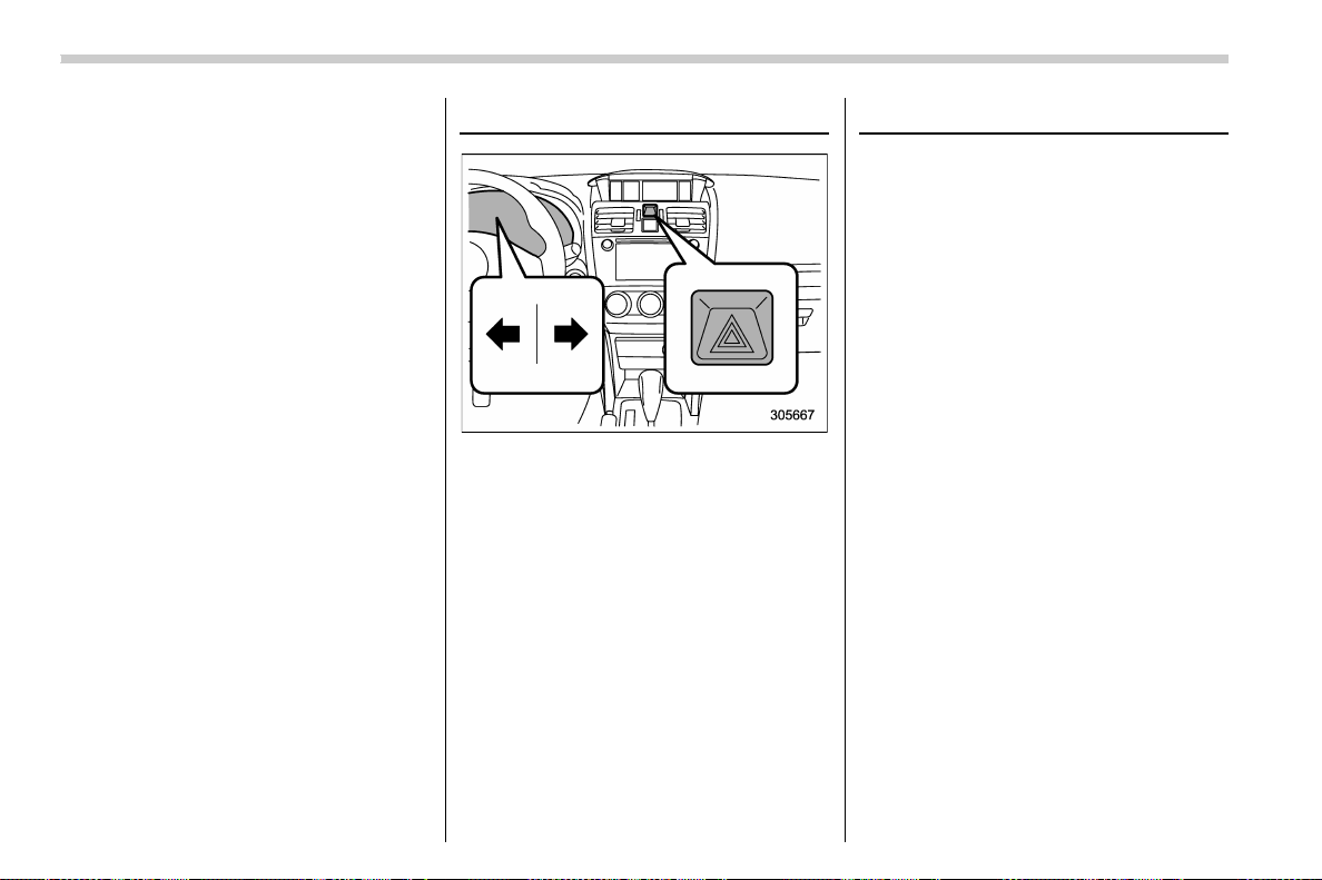
(150,1)
北米Model "A1700BE-B" EDITED: 2017/ 10/ 11
NOTE
. When operating the push-button
ignition switch, firmly press it.
. If you press the push-button ignition
switch quickly, the power may not turn
on or off.
. If the indicator light on the push-
button ignition switch flashes in green
when pressing the push-button ignition
switch, steering is locked. When this
occurs, press the push-button ignition
switch while turning the steering wheel
left and right.
! Battery drainage prevention func-
tion
When the push-button ignition switch is left
in the “ACC” or “ON” position for approxi-
mately 1 hour, the push-button ignition
switch will be automatically switched to
“OFF” to prevent the battery from going
dead. (In CVT models, this function is
activated when the select lever is in the “P”
position.)
! When access key fob does not
operate properly
Refer to “Access key fob – if access key
fob does not operate properly” F9-26.
Hazard warning flasher
Use the hazard warning flasher to warn
other drivers when you have to park your
vehicle under emergency conditions. The
hazard warning flasher works regardless
of the position of the ignition switch.
To turn on the hazard warning flasher,
push the hazard warning button on the
instrument panel. All the turn signal lights
and the turn signal indicator lights will
flash. To turn off the flasher, push the
button again.
NOTE
When the hazard warning flasher is on,
the turn signals do not work.
Meters and gauges
NOTE
Liquid-crystal displays are used in
some of the meters and gauges on the
combination meter. You will find their
indications hard to see if you wear
polarized glasses.
& Combination meter illumina-
tion
When you turn the ignition switch to the
“ON” position, the various parts of the
combination meter are illuminated in the
following sequence.
1. Warning lights, indicator lights, meter
needles, gauge needles illuminate.
2. Meter and gauge indications each
show MAX position.
3. Meter and gauge indications each
show MIN position.
4. Regular illumination (for driving) be-
gins.
Instruments and controls/Hazard warning flasher
3-8
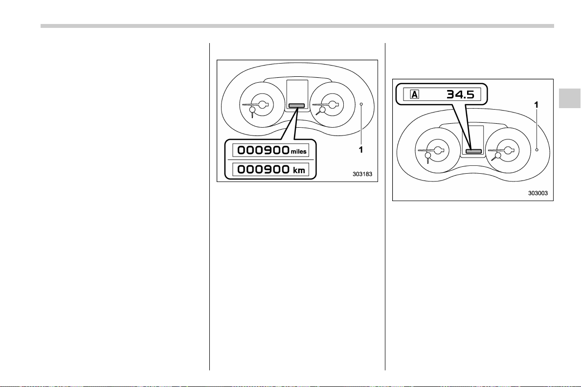
(151,1)
北米Model "A1700BE-B" EDITED: 2017/ 10/ 11
NOTE
This sequence of operations may not
take place if you quickly turn the
ignition switch to start the engine. This
is not a malfunction.
& Canceling the function for
meter/gauge needle move-
ment upon turning on the
ignition switch
It is possible to activate or deactivate the
movement of the meter needles and
gauge needles that takes place when you
turn the ignition switch to the “ON” position.
To change the setting, perform the proce-
dures described in “Gauge Initial Move-
ment” F3-43.
& Speedometer
The speedome ter shows the vehicle
speed. The digital speedometer can be
also displayed on the combination meter
display (color LCD).
& Odometer
The unit displayed varies depending on
the models.
1) Trip knob
This meter displays the odometer when
the ignition switch is in the “ON” position.
The odometer shows the total distance
that the vehicle has been driven.
If you press the trip knob when the ignition
switch is in the “LOCK”/“OFF” or “ACC”
position, the odometer/trip meter will light
up. If you do not press the trip knob within
10 seconds of illumination of the od-
ometer/trip meter, the odometer/trip meter
will turn off.
Also, if you open and close the driver’s
door within 10 seconds of illumination of
the odometer/trip meter, the odometer/trip
meter will turn off.
& Double trip meter
1) Trip knob
This meter displays the two trip meters
when the ignition switch is in the “ON”
position.
The trip meter shows the distance that the
vehicle has been driven since you last set
it to zero.
If you press the trip knob when the ignition
switch is in the “LOCK”/“OFF” or “ACC”
position, the odometer/trip meter will light
up. It is possible to switch between the A
trip meter and B trip meter indications
while the odometer/trip meter is lit up. If
you do not press the trip knob within 10
seconds of illumination of the odometer/
– CONTINUED –
Instruments and controls/Meters and gauges
3-9
3
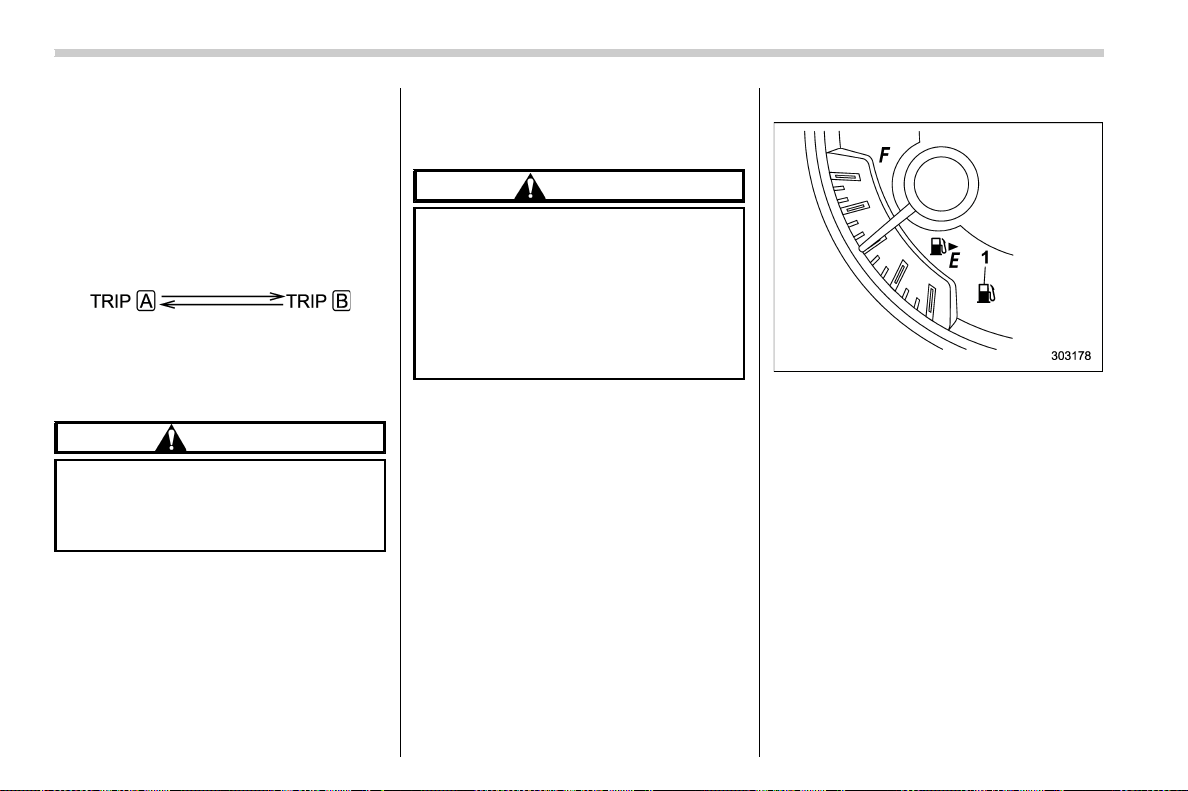
(152,1)
北米Model "A1700BE-B" EDITED: 2017/ 10/ 11
trip meter, the odometer/trip meter will turn
off.
Also, if you open and close the driver’s
door within 10 seconds of illumination of
the odometer/trip meter, the odometer/trip
meter will turn off.
You can switch the display as shown in the
following sequence by pressing the trip
knob.
To set the trip meter to zero, select the A
trip or B trip meter by pressing the knob
and keep the knob pressed for more than 2
seconds.
CAUTION
To ensure safety, do not attempt to
change the function of the indicator
while driving, as an accident could
result.
NOTE
If the connection between the combina-
tion meter and battery is broken for any
reason such as vehicle maintenance or
fuse replacement, the data recorded on
the trip meter will be lost.
& Tachometer
The tachometer shows the engine speed
in thousands of revolutions per minute.
CAUTION
Do not operate the engine with the
pointer of the tachometer in the red
zone. In this range, fuel injection will
be cut by the engine control module
to protect the engine from overrev-
ving. The engine will resume run-
ning normally after the engine speed
is reduced below the red zone.
& Fuel gauge
1) Low fuel warning light
The fuel gauge shows the approximate
amount of fuel remaining in the tank.
When the ignition switch is in the “LOCK”/
“OFF” or “ACC” position, the fuel gauge
shows “E” even if the fuel tank contains
fuel.
The gauge may move slightly during
braking, turning or acceleration due to fuel
level movement in the tank.
If you press the trip knob while the ignition
switch is in the “LOCK”/“OFF” or “ACC”
position, the fuel gauge’s dial will light up
and the needle will indicate the amount of
fuel remaining in the tank.
If, while the fuel gauge needle is indicating
the amount of fuel remaining in the tank,
Instruments and controls/Meters and gauges
3-10
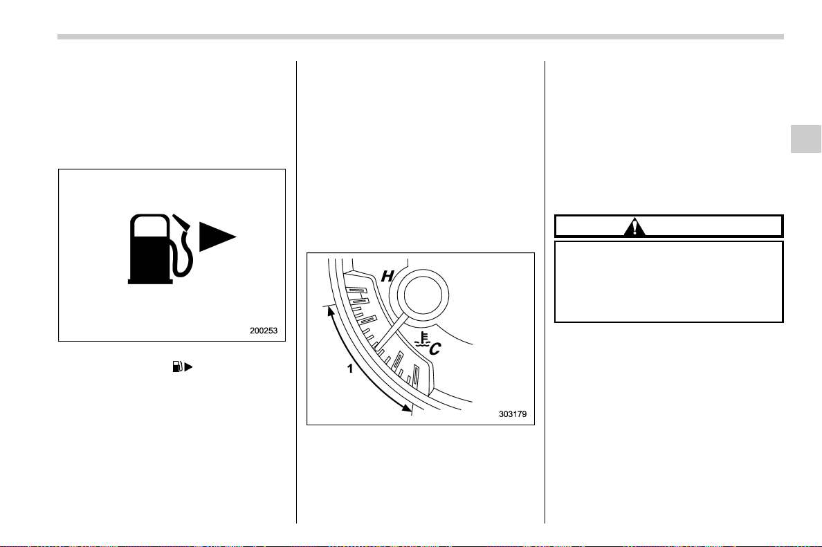
(153,1)
北米Model "A1700BE-B" EDITED: 2017/ 10/ 11
you (a) do not press the trip knob for 10
seconds or (b) open and close the driver’s
door, the fuel gauge needle will drop to the
“E” position and the dial and needle will
turn off.
NOTE
. You will see the “ ” sign in the fuel
gauge.
This indicates that the fuel filler door
(lid) is located on the right side of the
vehicle.
. When you have refueled, the fuel
gauge indicates the amount in the fuel
tank after starting the engine. Also, it
may take some time until the fuel gauge
indication stabilizes.
. The gauge indicates only an approx-
imate amount of fuel remaining in the
tank. Use this indication only as a
guide.
. If you refuel while the ignition switch
is in the “ON” position, the fuel gauge
may not indicate the correct amount of
the fuel in the fuel tank.
. If the refuel amount is less than
approximately 4.0 US gal (15 liters, 3.3
Imp gal), it may take some time until the
fuel gauge indication stabilizes.
& Temperature gauge
1) Normal operating range
The temp erature gauge shows engine
coolant temperature when the ignition
switch is in the “ON” position.
The coolant temp erature will vary in
accordance with the outside temperature
and driving conditions.
We recommend that you drive moderately
until the pointer of the temperature gauge
reaches near the middle of the range.
Engine operation is optimum with the
engine coolant at this temperature range
and high revving operation when the
engine is not warmed up enough should
be avoided.
CAUTION
If the pointer exceeds the normal
operating range, safely stop the
vehicle as soon as possible.
Refer to “Engine overheating” F9-
20.
– CONTINUED –
Instruments and controls/Meters and gauges
3-11
3
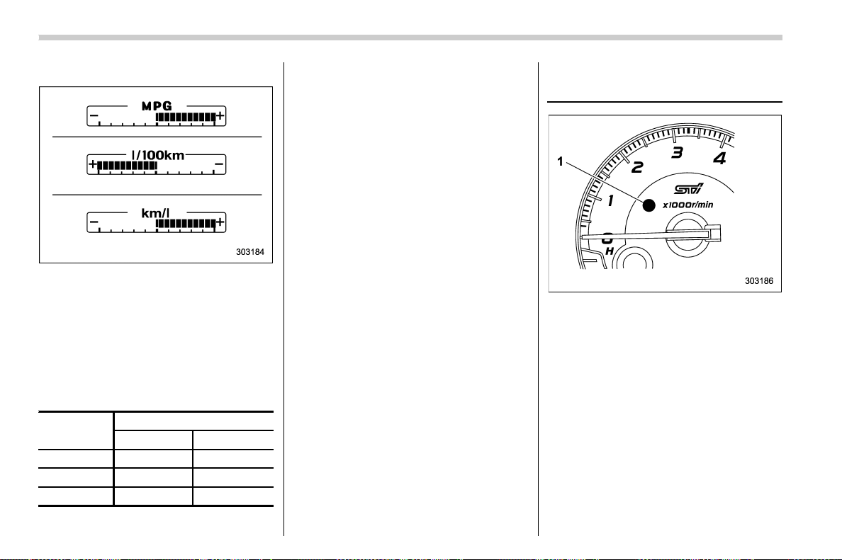
(154,1)
北米Model "A1700BE-B" EDITED: 2017/ 10/ 11
& ECO gauge
The unit displayed varies depending on
the models.
The ECO ga uge shows the difference
between the average rate of fuel con-
sumption since the trip meter was last
reset and the current rate of fuel consump-
tion.
The ECO gauge indicates the current fuel
efficiency as shown in the following chart.
Displayed
unit
Needle position
“+” side “-” side
MPG Better Poorer
l/100km Poorer Better
km/l Better
Poorer
NOTE
. The ECO gauge shows only an
approximate indication.
. After resetting the trip meter, the
average rate of fuel consumption is not
shown until driving 0.6 mile (1 km). Until
that time, the ECO gauge does not
operate.
REV indicator light and buz-
zer (STI)
1) REV indicator light
The REV alarm system has the following
functions.
. When the engine speed reaches the
level that was previously set, the REV
indicator light illuminates to inform you. At
this time, a buzzer also sounds if the
buzzer setting is activated.
. Whenever the engine speed enters the
red zone of the tachometer, the REV
indicator light flashes.
Instruments and controls/REV indicator light and buzzer (STI)
3-12
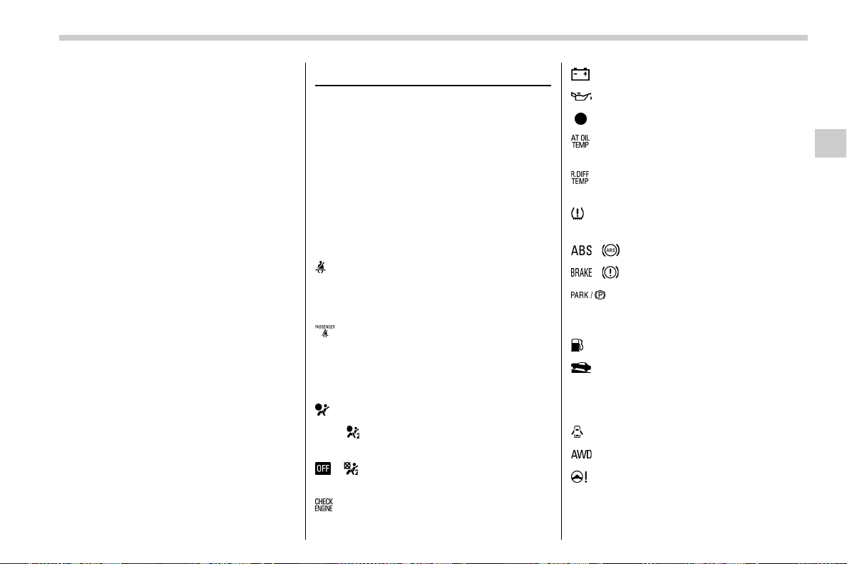
(155,1)
北米Model "A1700BE-B" EDITED: 2017/ 10/ 11
NOTE
Even if the REV alarm system is not set,
the REV indicator light will flash when-
ever the engine speed enters the red
zone of the tachometer.
To change the REV indicator settings,
perform the procedures described in
“REV settings (STI)” F3-43.
Warning and indicator lights
Several of the warning and indicator lights
illuminate when you initially turn the igni-
tion switch to the “ON” pos it ion . This
permits checking the operat ion of the
bulbs.
Apply the parki ng brake and tu rn the
ignition switch to the “ON” position. For
the system check, t he following lights
illuminate and then turn off after several
seconds or after the engine has started.
: Seatbelt warning light
(The seatbelt warning light turns off
only when the driver fastens the seat-
belt.)
: Front passenger’s seatbelt warning
light
(The seatbelt warning light turns off
only when the front seat passenger
fastens the seatbelt.)
: SRS airbag system warning light
ON /
: Front passenger’s frontal airbag
ON indicator light
/ : Front passenger’s frontal airbag
OFF indicator light
: CHECK ENGINE warning light/Mal-
function indicator light
: Charge warning light
: Oil pressure warning light
: REV indicator light (STI)
: AT OIL TEMP warning light
(CVT models)
: Rear differential oil temperature warn-
ing light (STI)
: Low tire pressure warning light
(U.S.-spec. models)
/ : ABS warning light
/ : Brake system warning light
: Electronic parking brake indicator
light (models with the electronic
parking brake system)
: Low fuel warning light
: Hill start assist warning light/Hill start
assist OFF indicator light (models
without electronic parking brake sys-
tem)
: Door open warning light
: AWD warning light (if equipped)
: Power steering warning light (except
STI)
– CONTINUED –
Instruments and controls/Warning and indicator lights
3-13
3
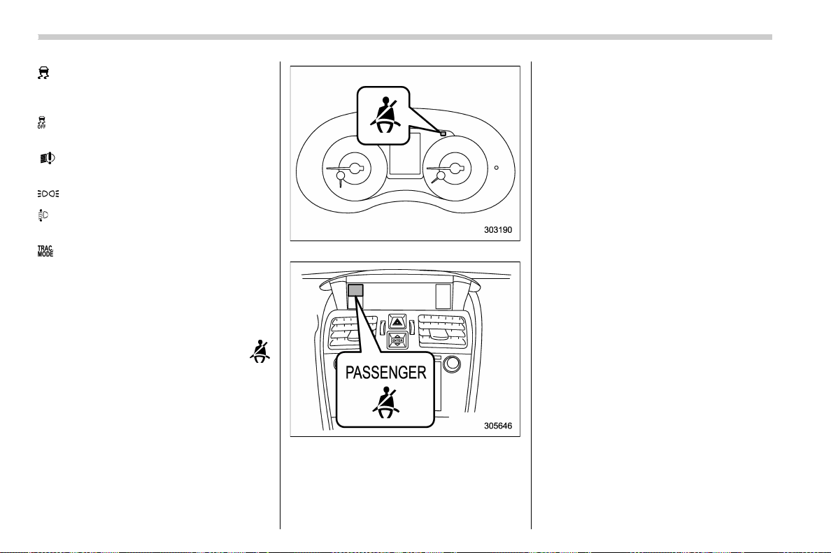
(156,1)
北米Model "A1700BE-B" EDITED: 2017/ 10/ 11
: Vehicle Dynamics Control warning light/
Vehi cl e Dynamic s Control opera tio n
indicator light
: Vehicle Dynamics Control OFF indicator
light
: LED headlight warning light (if
equipped)
: Headlight indicator light
: Automatic headlight beam leveler
warning light (if equipped)
: Traction mode indicator light
If any lights fail to illuminate, it indicates a
burned-out bulb or a malfunction of the
corresponding system.
Consult your authorized SUBARU dealer
for repair.
& Seatbelt warning light
and chime
Your vehicle is equipped with a seatbelt
warning device at the driver’s and front
passenger’s seat, as required by current
safety standards.
With the ignition switch turned to the “ON”
position, this device reminds the driver and
front passenger to fasten their seatbelts by
illuminating the warning lights in the loca-
tions indicated in the following illustration
and sounding a chime.
Driver’s warning light
Front passenger’s warning light
! Operation
If the driver and/or front passenger have/
has not yet fastened the seatbelt(s) when
the ignition switch is turned to the “ ON”
position, the seatbelt warning light(s) will
illuminate for 6 seconds, to warn that the
seatbelt(s) is/are unfastened. If the driver’s
seatbelt is not fastened, a chime will also
sound simultaneously.
NOTE
. If the driver’s and/or front passen-
ger’s seatbelt(s) are/is still not fastened
6 seconds later, the seatbelt warning
device operates as follows according
to the vehicle speed.
– At speeds lower than approxi-
mately 9 mph (15 km/h)
The warning light(s) for unfastened
seatbelt(s) will alternate between
steady illumination and flashing at
15-second intervals. The chime will
not sound.
– At speeds higher than approxi-
mately 9 mph (15 km/h)
The warning light(s) for unfastened
seatbelt(s) will alternate between
flashing and steady illumination at
15-second intervals and the chime
will sound while the warning light(s)
is/are flashing.
. It is possible to cancel the warning
Instruments and controls/Warning and indicator lights
3-14
(157,1)
北米Model "A1700BE-B" EDITED: 2017/ 10/ 11
operation that follows the 6-second
warning after turning ON the ignition
switch. When the ignition switch is
turned ON next time, however, the
complete sequence of the warning
operation resumes. For further details
about canceling the warning operation,
please contact your SUBARU dealer.
If there is no passenger on t he front
passenger’s seat, the seatbelt warning
device for the front passenger’s seat will
be deactivated. The front passenger’s
occupant detecti on system moni tors
whether or not there is a passenger on
the front passenger’s seat.
Observe the following precautions. Failure
to do so may prevent the device from
functioning correctly or cause the device to
fail.
. Do not install any accessory such as a
table or TV onto the seatback.
. Do not store a heavy load in the
seatback pocket.
. Do not allow the rear seat occupant to
place his/her hands or legs on the front
passenger’s seatback, or allow him/her to
pull the seatback.
. Do not use front seats with their back-
ward-forward position and seatback not
being locked into place securely. If any of
them are not locked securely, adjust them
again. For adjusting procedure, refer to
“Front seats” F1-2.
If the seatbelt warning device for the front
passenger’s seat does not function cor-
rectly (e.g., it is activated even when the
front passenger’s seat is empty or it is
deactivated even when the front passen-
ger has not fastened his/her seatbelt), take
the following actions.
. Ensure that no article is placed on the
seat other than a child restraint system and
its child occupant, although we strongly
recommend that all children sit in the rear
seat properly restrained.
. Ensure that there is no article left in the
seatback pocket.
. Ensure that the backward-forward po-
sition and seatback of front passenger’s
seat are locked into place securely by
moving the seat back and forth.
If still the seatbelt warning device for front
passenger’s seat does not function cor-
rectly after taking relevant corrective ac-
tions described above, immediately con-
tact your SUBARU dealer for an inspec-
tion.
& SRS airbag system
warning light
For details about the SRS airbag system
warning light, refer to “SRS airbag system
monitors” F1-62.
WARNING
If the warning light exhibits any of
the following conditions, there may
be a malfunction in the seatbelt
pretensioners and/or SRS airbag
system.
. Flashing or flickering of the warn-
ing light
. No illumination of the warning
light when the ignition switch is
first turned to the “ON” position
. Continuous illumination of the
warning light
. Illumination of the warning light
while driving
Immediately take your vehicle to
your nearest SUBARU dealer to
have the system checked. Unless
checked and properly repaired, the
seatbelt pretensioners and/or SRS
airbag will not operate properly in
the event of a collision, which may
increase the risk of injury.
– CONTINUED –
Instruments and controls/Warning and indicator lights
3-15
3
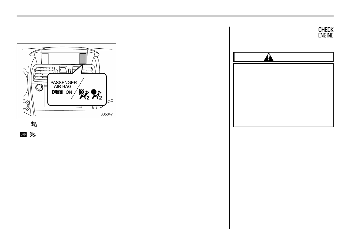
(158,1)
北米Model "A1700BE-B" EDITED: 2017/ 10/ 11
& Front passenger’s frontal air-
bag ON and OFF indicators
ON / : Front passenger’s frontal airbag ON
indicator
/ : Front passenger’s frontal airbag OFF
indicator
The front passenger’s frontal airbag ON
and OFF indicators show you the status of
the front passenger’s SRS frontal airbag.
The indicators are located next to the clock
in the center portion of the dashboard.
When the ignition switch is turned to the
“ON” position, both the ON and OFF
indicators illuminate for 6 seconds during
which time the system is checked. Follow-
ing the system check, both indicators turn
off for 2 seconds. After that, one of the
indicators illuminates depending on the
status of the front passenger’s SRS frontal
airbag determined by the SUBARU ad-
vanced frontal airbag system monitoring.
If the front passenger’s SRS frontal airbag
is activated, the passenger’s frontal airbag
ON indicator will illuminate while the OFF
indicator will remain off.
If the front passenger’s SRS frontal airbag
is deactivated, the passenger’s fro ntal
airbag ON indicator will remain off while
the OFF indicator will illuminate.
With the ignition switch turned to the “ON”
position, if both the ON and OFF indicators
remain illuminated or off simultaneously
even after the system check period, the
system is malfunctioning. Contact your
SUBARU dealer immediately for an in-
spection.
& CHECK ENGINE warn-
ing light/Malfunction in-
dicator light
CAUTION
If the CHECK ENGINE light illumi-
nates while you are driving, have
your vehicle checked/repaired by
your SUBARU dealer as soon as
possible. Continued vehicle opera-
tion without having the emission
control system checked and re-
paired as necessary could cause
serious damage, which may not be
covered by your vehicle’s warranty.
If this light illuminates steadily or blinks
while the engine is running, it may indicate
that there is at least one problem or
potential problem somewhere in the emis-
sion control system.
! If the light illuminates steadily
If the light illuminates steadily while driving
or does not turn off after the engine starts,
an emission control system malfunction
has been detected.
You should have your vehicle checked by
an authorized SUBARU dealer immedi-
ately.
Instruments and controls/Warning and indicator lights
3-16
(159,1)
北米Model "A1700BE-B" EDITED: 2017/ 10/ 11
NOTE
This light also illuminates when the fuel
filler cap is not tightened until it clicks.
If you have recently refueled your vehicle,
the cause of the CHECK ENGINE warning
light/malfunction indicator light illuminating
could be a loose or missing fuel filler cap.
Remove the cap and retighten it until it
clicks. Make sure nothing is interfering with
the sealing of the cap. Tightening the cap
will not make the CHECK ENGINE warn-
ing light/malfunction indicator light turn off
immediately. It may take several driving
trips. If the light does not turn off, take your
vehicle to your authorized SUBARU dealer
immediately.
! If the light is blinking
If the light is blinking while driving, an
engine misfire condition has been de-
tected which may damage the emission
control system.
To prevent serious damage to the emis-
sion control system, you should do the
following.
. Reduce vehicle speed.
. Avoid hard acceleration.
. Avoid steep uphill grades.
. Reduce the amount of cargo, if possi-
ble.
The CHECK ENGINE warning light may
stop blinking and illuminate steadily after
several driving trips. You should have your
vehicle checked by an authorized
SUBARU dealer immediately.
& Charge warning light
If this light illuminates when the engine is
running, it may indicate that the charging
system is not working properly.
If the light illuminates while driving or does
not turn off after the engine starts, stop the
engine at the first safe opportunity and
check the alternator belt. If the belt is
loose, broken or if the belt is in good
condition but the light remains illuminated,
contact your nearest SUBARU dealer
immediately.
& Oil pressure warning
light
If this light illuminates when the engine is
running, it may indicate that the engine oil
pressure is low and the lubricating system
is not working properly.
If the light illuminates while driving or does
not turn off after the engine starts, stop the
engine at the first safe opportunity and
check the engine oil level. If the oil level is
low, add oil immediately. If the engine oil is
at the proper level but the light remains
illuminated, contact your nearest
SUBARU dealer immediately.
For details about checking the engine oil
level or adding the engine oil, refer to
“Engine oil” F11-13.
CAUTION
Do not operate the engine with the
oil pressure warning light on. This
may cause serious engine damage.
& Engine low oil level
warning indicator
(except STI)
This indicator appears when the engine oil
level decreases to the lower limit.
If the engine low oil level warning indicator
appears while driving, park the vehicle in a
safe and level location, and then check the
engine oil level. When the engine oil level
is not within the normal range, refill with
engine oil. Refer to “Engine oil” F11-13.
If the warning indicator does not disappear
after refilling the engine oil, or the warning
indicator appears even though the engine
oil level is within the normal range, have
the vehicle checked by a SUBARU dealer.
– CONTINUED –
Instruments and controls/Warning and indicator lights
3-17
3
(160,1)
北米Model "A1700BE-B" EDITED: 2017/ 10/ 11
NOTE
. After replacing or adding the engine
oil, if the engine oil level is within the
normal range when restarting the en-
gine on a level surface, the warning
indicator will be off.
. The warning indicator may appear
temporarily in the following conditions
because a low oil level may be detected
as a result of significant oil movement
in the engine.
– when the vehicle is considerably
inclined on an uphill or steep slope
– when the vehicle has continu-
ously accelerated and decelerated
– when the vehicle is continuously
turned
– when the vehicle is driven on a
road that alternates continuously
between uphill and downhill
& Windshield washer
fluid warning indicator
This indicator appears when the fluid level
in the windshield washer fluid tank de-
creases to the lower limit (approximately
1.1 US qt, 1.0 liter, 0.9 Imp qt).
& AT OIL TEMP warning
light (CVT models)
If this light illuminates when the engine is
running, it may indicate that the transmis-
sion fluid temperature is too hot.
If the light illuminates while driving, im-
mediately stop the vehicle in a safe place
and let the engine idle until the warning
light turns off.
! Transmission control system warn-
ing
If the “AT OIL TEMP” warning light flashes
after the engine has started, it may indicate
that the transmission control system is not
working properly. Contact your nearest
SUBARU dealer for service immediately.
& Rear differential oil
temperature warning
light (STI)
CAUTION
If the R.DIFF TEMP warning light
illuminates, reduce vehicle speed
and stop the vehicle in a safe loca-
tion as soon as possible. Continuing
to drive with this light illuminated
may damage the rear differential and
other parts of the powertrain.
If this light illuminates when the engine is
running, it may indicate that the rear
differential oil temperature is too hot.
At this time, the driver’s control center
differential will automatically cancel the
current torque-distribution ratio setting and
adopt its minimum ratio.
If the light illuminates while driving, reduce
vehicle speed and stop the vehicle in the
nearest safe location. Park the vehicle for
several minutes. After the light turns off,
you can start driving.
If the light does not turn off, contact the
nearest SUBARU dealer for service.
NOTE
. If the tire pressures are not correct
and/or the tires are not all the same size
and brand, the rear differential will be
heavily loaded when the vehicle is
driven, resulting in an abnormally high
oil temperature.
. The rear differential oil will deterio-
rate if its temperature increases en-
ough for the rear differential oil tem-
perature warning light to illuminate. It is
advisable to have the rear differential
oil replaced as soon as possible.
Instruments and controls/Warning and indicator lights
3-18
(161,1)
北米Model "A1700BE-B" EDITED: 2017/ 10/ 11
& Low tire pressure
warning light (U.S.-spec.
models)
When the ignition switch is turned to the
“ON” position, the low tire pressure warn-
ing light will illuminate for approximately 2
seconds to check that the tire pressure
monitoring system (TPMS) is functioning
properly. If there is no problem and all tires
are properly inflated, the light will turn off.
Each tire, including the spare (if provided),
should be checked monthly when cold and
inflated to the inflation pressure recom-
mended by the vehicle manufacturer on
the vehicle placard or tire inflation pres-
sure label. (If your vehicle has tires of a
different size than the size indicated on the
vehicle placard or tire inflation pressure
label, you should determine the proper tire
inflation pressure for those tires.)
As an added safety feature, your vehicle
has been equipped with a tire pressure
monitoring system (TPMS) that illuminates
a low tire pressure telltale when one or
more of your tires is significantly under-
inflated. Accordingly, when the low tire
pressure telltale illuminates, you should
stop and check your tires as soon as
possible, and inflate them to the proper
pressure. Driving on a significantly under-
inflated tire causes the tire to overheat and
can lead to tire failure. Under-inflation also
reduces fuel efficiency and tire tread life,
and may affect the vehicle’s handling and
stopping ability.
Please note that the T PMS is not a
substitute for proper tire maintenance,
and it is the driver’s responsibility to
maintain correct tire pressure, even if
under-inflation has not reached the level
to trigger illumination of the TPMS low tire
pressure telltale.
Your vehicle has also been equipped with
a TPMS malfunction indicator to indicate
when the system is not operating properly.
The TPMS malfunction indicator is com-
bined with the low tire pressure telltale.
When the system detects a malfunction,
the telltale will flash for approximately one
minute and then re main conti nuously
illuminated. This sequence will continue
upon subsequent vehicle start-ups as long
as the malfunction exists. When the mal-
function indicator is illuminated, the sys-
tem may not be able to detect or signal low
tire pressure as intended. TPMS malfunc-
tions may occur for a variety of reasons,
including the installation of replacement or
alternate tires or wheels on the vehicle that
prevent the TPMS from functioning prop-
erly. Always check the TPMS malfunction
telltale after replacing one or more tires or
wheels on your vehicle to ensure that the
replacement or alternate tires and wheels
allow the TPMS to continue to function
properly.
Should the warning light illuminate steadily
after blinking for approximately one min-
ute, have the system inspected by your
nearest SUBARU dealer as soon as
possible.
WARNING
If this light does not illuminate
briefly after the ignition switch is
turned ON or the light illuminates
steadily after blinking for approxi-
mately one minute, you should have
your Tire Pressure Monitoring Sys-
tem checked at a SUBARU dealer as
soon as possible.
If this light illuminates while driving,
never brake suddenly. Instead, per-
form the following procedure. Other-
wise an accident involving serious
vehicle damage and serious perso-
nal injury could occur.
1) Keep driving straight ahead while
gradually reducing speed.
2) Slowly pull off the road to a safe
place.
If this light still illuminates while
driving after adjusting the tire pres-
sure, a tire may have significant
– CONTINUED –
Instruments and controls/Warning and indicator lights
3-19
3
(162,1)
北米Model "A1700BE-B" EDITED: 2017/ 10/ 11
damage and a fast leak that causes
the tire to lose air rapidly. If you have
a flat tire, refer to “Flat tires” F9-5.
When a spare tire is mounted or a
wheel rim is replaced without the
original pressure sensor/transmitter
being transferred, the Low tire pres-
sure w arning light wil l illuminate
steadily after blinking for approxi-
mately one minute. This indicates
the TPMS is unable to monitor all
four road wheels. Contact your
SUBARU dealer as soon as possible
for tire and sensor replacement and/
or system resetting.
If the light illuminates steadily after
blinking for approximately one min-
ute, promptly contact a SU BARU
dealer to have the system inspected.
CAUTION
The tire pressure monitoring system
is NOT a substitute for manually
checking tire pressure. The tire
pressure should be checked peri-
odically (at least monthly) using a
tire gauge. After any change to tire
pressure(s), the tire pressure mon-
itoring system will not re-check tire
inflation pressures until the vehicle
is first driven to a vehicle speed of at
least 20 mph (32 km/h). After adjust-
ing the tire pressures, increase the
vehicle speed to at least 20 mph (32
km/h) to start the TPMS re-checking
of the tire inflation pressures. If the
tire pressures are now above the
severe low pressure threshold, the
low tire pressure wa rning light
should turn off a few minutes later.
Therefore, be sure to install the
specified size for the front and rear
tires.
& ABS warning light
CAUTION
. If any of the following conditions
occur, we recommend that you
have the ABS system repaired at
the first available opportunity by
your SUBARU dealer.
– The warning light does not
illuminate when the ignition
switch is turned to the “ON”
position.
– The warning light illuminates
when the ignition switch is
turned to the “ON” position,
but it does not turn off even
after starting the vehicle.
– The warning light illuminates
while driving.
. When the warning light is on (and
the brake system warning light is
off), the ABS function shuts
down. However, the conventional
brake system continues to oper-
ate normally.
The ABS warning light illuminates together
with the brake system warning light if the
EBD system ma lfunctions. For further
details of the EBD system malfunction
warning, refer to “Brake system warning
light” F3-21.
NOTE
If the warning light behavior is as
described in the following conditions,
the ABS system may be considered
normal.
. The warning light illuminates when
the ignition switch is turned to the “ON”
position and turns off approximately 2
seconds after the engine has started.
. The warning light illuminates right
after the engine is started but turns off
immediately, remaining off.
. The warning light remains illumi-
nated after the engine has been started,
but it turns off while driving.
Instruments and controls/Warning and indicator lights
3-20
(163,1)
北米Model "A1700BE-B" EDITED: 2017/ 10/ 11
. The warning light illuminates while
driving, but it turns off immediately and
remains off.
When driving with an insufficient battery
voltage such as when the engine is jump
started, the ABS warning light may illumi-
nate. This is due to the low battery voltage
and does not indicate a malfunction. When
the battery becomes fully charged, the
light will turn off.
& Brake system
warning light
WARNING
. Driving with the brake system
warning light on is dangerous.
This indicates your brake system
may not be working properly. If
the light remains illuminated,
have the brakes inspected by a
SUBARU dealer immediately.
. If at all in doubt about whether the
brakes are operating properly, do
not drive the vehicle. Have your
vehicle towed to t he nearest
SUBARU dealer for repair.
. For models with the electronic
parking brake: If the brake sys-
tem warning light illuminates, the
electronic parking brake system
may be malfunctioning. Immedi-
ately stop your vehicle in a safe
location, use tire stops under the
tires to prevent the vehicle from
moving and contact your
SUBARU dealer. For details, refer
to “Electronic parking brake
(models with electronic parking
brake system)” F7-43.
NOTE
For models with the electronic parking
brake:
. Even if the brake system warning
light illuminates, if the warning light
behavior is as described in the follow-
ing examples, the electronic parking
brake system is not malfunctioning.
– The warning light turns off when
the electronic parking brake is ap-
plied or released.
– The warning light turns off when
the ignition switch is turned to the
“ON” position again.
. The brake system warning light may
illuminate immediately after the engine
is started. However, it is not malfunc-
tioning if the warning light turns off
after the electronic parking brake is
released.
. The brake system warning light may
illuminate after the electronic parking
brake is frequently applied and re-
leased. However, the electronic parking
brake system is not malfunctioning if
the light turns off for a short period of
time.
. When the engine is started while the
electroni c parking brake is applied/
released, the system may judge an
abnormal situation and the warning
light may illuminate. If the warning light
illuminates, turn the ignition switch
once to the “LOCK/OFF” position and
then restart the engine. Then, apply/
release the electronic parking brake. If
the warning light turns off, the system
will be restored.
This light has the following functions.
! Parking brake indicator (models
without electronic parking brake
system)
This light illuminates with the parking
brake applied while the ignition switch is
in the “ON” position. It turns off when the
parking brake is fully released.
– CONTINUED –
Instruments and controls/Warning and indicator lights
3-21
3

(164,1)
北米Model "A1700BE-B" EDITED: 2017/ 10/ 11
! Brake fluid level warning
This light illuminates when the brake fluid
level has dropped to near the “MIN” level of
the brake fluid reservoir with the ignition
switch in the “ON” position and with the
parking brake fully released.
If the brake system warning light should
illuminate while driving (with the parking
brake fully released and with the ignition
switch positioned in “ON”), it could be an
indication of leaking of brake fluid or worn
brake pads. If this occurs, immediately
stop the vehicle at the nearest safe place
and check the brake fluid level. If the fluid
level is below the “MIN” mark in the
reservoir, do not drive the vehicle. Have
the vehicle towed to the nearest SUBARU
dealer for repair.
! Electronic Brake Force Distribution
(EBD) system warning
The brake system warning light also
illuminates if a malfunction occurs in the
EBD system. In that event, it illuminates
together with the ABS warning light.
The EBD system may be malfunctioning if
the brake system warning light and ABS
warning light illuminate simultaneously
while driving.
Even if the EBD system fails, the conven-
tional braking system will still function.
However, the rear wheels will be more
prone to locking when the brakes are
applied harder than usual and the vehicle’s
motion may therefore become somewhat
harder to control.
If the brake system warning light and ABS
warning light illuminate simultaneously,
take the following steps.
1. Stop the vehicle in the nearest safe, flat
place.
2. Shut down the engine, apply the
parking brake and then restart it.
3. Release the par king brake. If both
warning lights turn off, the EBD system
may be malfunctioning. Drive carefully to
the nearest SUBARU dealer and have the
system inspected.
4. If both warning lights illuminate again
and remain illuminated after the engine
has been restarted, shut down the engine
again, apply the parking brake, and check
the brake fluid level.
5. If the brake fluid level is not below the
“MIN” mark, the EBD system may be
malfunctioning. Drive carefully to the
nearest SUBARU dealer and have the
system inspected.
6. If the brake fluid level is below the
“MIN” mark, DO NOT drive the vehicle.
Instead, have the vehicle towed to the
nearest SUBARU dealer for repair.
! Electronic parking brake system
warning (models with electronic
parking brake system)
The brake system warning light illuminates
when the electronic parking brake system
is malfunctioning. If the warning light
illuminates, promptly park in a safe loca-
tion as soon as possible and contact your
SUBARU dealer.
The brake system warning light remains
illuminated when the parking brake cannot
be released even if the parking brake
switch is pushed. For details, refer to
“Electronic p arking brake (models with
electronic parking brake system) ” F7-43.
! Frequent operation warning
The brake system warning light illuminates
and a chirp sound will be heard if the
parking b rake switch is operated too
frequently. In this case, the operation of
the parking brake switch is restricted to
protect the electronic parking brake sys-
tem.
! Vacuum pump system warning (ex-
cept STI)
This light illuminates when a malfunction is
detected in the vacuum pump system.
NOTE
The vacuum pump system assists the
boost pressure when driving at high
Instruments and controls/Warning and indicator lights
3-22
(165,1)
北米Model "A1700BE-B" EDITED: 2017/ 10/ 11
altitudes while the engine is cold.
& Electronic parking
brake indicator light
(models with electronic
parking brake system)
! Parking brake indicator
The light illuminates with the parking brake
applied while the ignition switch is in the
“ON” position. It turns off when the parking
brake is fully released.
! Electronic parking brake system
warning
WARNING
. When you release the electronic
parking brake while the engine is
running, the electronic parking
brake indicator light will turn off.
However, if the light still illumi-
nates, stop the vehicle in a safe
place immediately and have the
system inspected by a SUBARU
dealer.
. If at all in doubt about whether the
brakes are operating properly, do
not drive the vehicle. Have your
vehicle towed to t he nearest
SUBARU dealer for repair.
. If the electron ic parking brake
indicator light flashes, the elec-
tronic parking brake system may
be malfuncti oning. Immediately
stop your vehicle in a safe loca-
tion, use tire stops under the tires
to prevent the vehicle from mov-
ing and contact your SUBARU
dealer. For details, refer to “Elec-
tronic parking brake (models with
electronic parking brake s ys-
tem)” F7-43.
NOTE
. When the ignition switch is turned to
the “LOCK”/“OFF” position with the
electronic parking brake applied, the
electronic parking brake indicator light
remains illuminated for approximately
30 seconds and then turns off.
. When the electronic parking brake
switch is pulled to apply the electronic
parking brake while the ignition switch
is in the “LOCK”/“OFF” position, the
electronic parking brake indicator light
illuminates, remains illuminated for
approximately 30 seconds and then
turns off.
. Even if the electronic parking brake
indicator light flashes, if the warning
light behavior is as described in the
following examp les, the e lectronic
parking brake system is not malfunc-
tioning.
– The indicator light turns off when
the electronic parking brake is re-
leased.
. The electronic parking brake indica-
tor light may flash immediately after the
engine is started. However, it is not
malfunctionin g if the i ndicato r light
turns off after the electronic parking
brake is released.
. The electronic parking brake indica-
tor light may flash after the electronic
parking brake is frequently applied and
released. However, the electronic park-
ing brake system is not malfunctioning
if the light turns off for a short period of
time.
The electronic parking brake indicator light
flashes when the electronic parking brake
system is malfunctioning. If the indicator
light flashes, promptly park in a safe
location as soon as possible and contact
your SUBARU dealer.
The electronic parking brake indicator light
remains illuminated when the parking
brake cannot be released even if the
parking brake switch is pushed. For de-
tails, refer to “Electronic parking brake
(models wit h electro nic par kin g brake
system)” F7-43.
– CONTINUED –
Instruments and controls/Warning and indicator lights
3-23
3
(166,1)
北米Model "A1700BE-B" EDITED: 2017/ 10/ 11
! Parking brake apply inhibit warn-
ing
The electronic parking brake indicator light
flashes for 10 seconds and a chirp sound
will be heard if the parking brake switch is
operated when the parking brake cannot
be applied.
! Frequent operation warning
The electronic parking brake indicator light
flashes for 10 seconds and a chirp sound
will be heard if the parking brake switch is
operated too frequently. In this case, the
operation of the parking brake switch is
restricted to protect the electronic parking
brake system.
NOTE
Wait until the indicator light turns off.
& Low fuel warning light
The low fuel warning light illuminates when
the tank is nearly empty, at approximately
2.6 US gal (10.0 liters, 2.2 Imp gal). It only
operates when the ignition switch is in the
“ON” position.
CAUTION
Promptly put fuel in the tank when-
ever the low fuel wa rning light
illuminates. Engine misfires as a
result of an empty tank could cause
damage to the engine.
& Hill start assist warning
light/Hill start assist
OFF indicator light
(models without electro-
nic parking brake sys-
tem)
! Hill start assist warning light
While the engine is running, if there are
any malfunctions in the Hill start assist
system, the warning light will illuminate.
WARNING
When the Hill start assist warning
light illuminates, have the vehicle
inspected at an authorized SUBARU
dealer.
! Hill start assist OFF indicator light
While the Hill start assist system is
deactivated, the H ill start assist OFF
indicator light illuminates continuously to
inform the driver that the Hill start assist
system is not operational.
& Auto Vehicle Hold ON
indicator light (models
with electronic parking
brake system)
CAUTION
If the Auto Vehicle Hold ON indicator
light does not illuminate even when
the Auto Vehicle Hold switch is
pressed to activate the Auto Vehicle
Hold function, the electronic parking
brake system may be malfunction-
ing. Immediately stop the vehicle in
a safe location and contact your
SUBARU dealer.
This indicator light illuminates when the
Auto Vehicle Hold is activated. For details,
refer to “To turn on/off the Auto Vehicle
Hold function” F7-47.
& Auto Vehicle Hold op-
eration indicator light
(models with electronic
parking brake system)
This indicator light illuminates while the
vehicle is stopped by the Auto Vehicle Hold
function. For details, refer to “To operate
the Auto Vehicle Hold function” F7-48.
Instruments and controls/Warning and indicator lights
3-24
(167,1)
北米Model "A1700BE-B" EDITED: 2017/ 10/ 11
& Door open warning light
The warning light illuminates if any door or
the trunk lid is not fully closed. This
function is effective even if the ignition
switch is in the “LOCK”/“OFF” or “ACC”
position, or the key is removed from the
ignition switch.
Always make sure this light is not illumi-
nated before you start to drive.
& All-Wheel Drive warn-
ing light (if equipped)
This light flashes if the vehicle is driven
with tires of differing diameters fitted on the
wheels or with an excessively low air
pressure in any of the tires.
WARNING
Continued driving with the AWD
warning light flashing can lead to
powertrain damage. I f the AWD
warning light flashes, promptly park
in a safe location and then check
whether all four tires are the same
diameter and whether any of the
tires has a puncture or has lost air
pressure.
NOTE
If the temporary spare tire is used, the
AWD warning light may flash. Use of the
temporary spare tire should therefore
be restricted to the minimum time
necessary. Replace the temporary
spare tire with a conventional tire as
soon as possible.
& Power steering warning
light (except STI)
While the engine is running, this warning
light illuminates when a malfunction has
been detected in the electric power steer-
ing system.
CAUTION
When the power steering warning
light is illuminated, there may be
more resistance when the steering
wheel is operated. Drive carefully to
the nearest SUBARU dealer and
have the vehicle inspected immedi-
ately.
NOTE
If the steering wheel is operated in the
following ways, the power steering
control system may temporarily limit
the power assist in order to prevent the
system components, such as the con-
trol computer and drive motor, from
overheating.
. The steering wheel is operated fre-
quently and turned sharply while the
vehicle is maneuvered at extremely low
speeds, such as while frequently turn-
ing the steering wheel during parallel
parking.
. The steering wheel remains in the
fully turned position for a long period of
time.
At this time, there will be more resis-
tance when steering. However this is
not a malfunction. Normal steering
force will be restored after the steering
wheel is not operated for a while and
the power steering control system has
an opportunity to cool down. However,
if the power steering is operated in a
non-standard way which causes power
assist limitation to occur too frequently,
that may result in a malfunction of the
power steering control system.
& LED headlight warning
light (if equipped)
This light illuminates if the LED headlights
malfunction. Have your vehicle inspected
at a SUBARU dealer as soon as possible.
– CONTINUED –
Instruments and controls/Warning and indicator lights
3-25
3
(168,1)
北米Model "A1700BE-B" EDITED: 2017/ 10/ 11
& Vehicle Dynamics Con-
trol warning light/Vehicle
Dynamics Control op-
eration indicator light
! Vehicle Dynamics Control warning
light
CAUTION
The Vehicle Dynamics Control sys-
tem provides its ABS control
through the electrical circuit of the
ABS. Accordingly, if the ABS is
inoperative, the Vehicle Dynamics
Control system becomes unable to
provide ABS control. As a result, the
Vehicle Dynamics Control system
also becomes inoperative, causing
the warning light to illuminate.
Though both the Vehicle Dynamics
Control and ABS are inoperative in
this case, the ordinary functions of
the brake system are still available.
You will be safe while driving with
this condition, but drive carefully
and have your vehicle checked at a
SUBARU dealer as soon as possi-
ble.
NOTE
. If the electrical circuit of the Vehicle
Dynamics Control system itself mal-
functions, the warning light only illumi-
nates. At this time, the ABS (Anti-lock
Brake System) remains fully opera-
tional.
. The warning light illuminates when
the electronic control system of the
ABS/Vehicle Dynamics Control system
malfunctions.
The Vehicle Dynamics Control system is
probably i noperative under any of the
following conditions. Have your vehicle
checked at a SUBARU dealer immedi-
ately.
. The warning light does not illuminate
when the ignition switch is turned to the
“ON” position.
. The warning light illuminates while the
vehicle is running.
NOTE
If the warning light behavior is as
described in the following examples,
the Vehicle Dynamics Control system
may be considered normal.
. The warning light illuminates when
the ignition switch is turned to the “ON”
position and turns off approximately 2
seconds after the engine has started.
. The warning light illuminates right
after the engine is started but turns off
immediately, remaining off.
. The warning light illuminates after
the engine has started and turns off
while the vehicle is subsequently being
driven.
. The warning light illuminates while
driving, but it turns off immediately and
remains off.
. The warning light illuminates when
the engine has stalled and continues to
illuminate after the engine has been
restarted. However, it will turn off once
the vehicle starts moving.
Instruments and controls/Warning and indicator lights
3-26

(169,1)
北米Model "A1700BE-B" EDITED: 2017/ 10/ 11
! Vehicle Dynamics Control operation
indicator light
The indicator light flashes during activation
of the skid suppression function and during
activation of the traction control function.
NOTE
. The light may remain illuminated for
a short period of time after the engine
has been started, especially in cold
weather. This does not indicate the
existence of a problem. The light
should turn off as soon as the engine
has warmed up.
. The indicator light illuminates when
the engine has developed a problem
and the CHECK ENGINE warning light/
malfunction indicator light is on.
The Vehicle Dynamics Control system is
probably malfunctioning under the follow-
ing condition. Have your vehicle checked
at a SUBARU dealer as soon as possible.
. The light does not turn off even after the
lapse of several minutes (the engine has
warmed up) after the engine has started.
& Vehicle Dynamics Control OFF indicator light/Traction mode
indicator light
/
The indicator light shows the activated/deactivated conditions as follows.
Activated/deactivated status for each function
Traction Control
Vehicle
Dynamics
Control system
ABS
Indicator light
Turn off Activated Activated Activated
Deactivated Activated Activated
Deactivated Deactivated
Activated
For details about the Traction Control and Vehicle Dynamics Control system, refer to
“Vehicle Dynamics Control system” F7-37.
– CONTINUED –
Instruments and controls/Warning and indicator lights
3-27
3
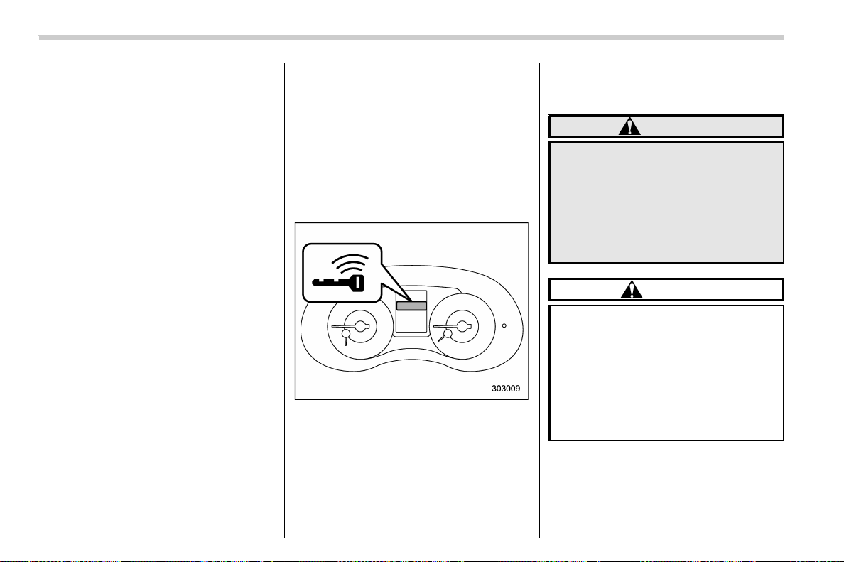
(170,1)
北米Model "A1700BE-B" EDITED: 2017/ 10/ 11
! Vehicle Dynamics Control OFF in-
dicator light
This light illuminates when the Vehicle
Dynamics Control OFF switch is operated
to select the traction mode or the Vehicle
Dynamic Control OFF mode. For details,
refer to “Vehicle Dynamics Control sys-
tem” F7-37.
NOTE
. The light may remain illuminated for
a while after the engine has been
started, especially in cold weather. This
does not indicate the existence of a
problem. The light should turn off as
soon as the engine has warmed up.
. The indicator light illuminates when
the engine has developed a problem
and the CHECK ENGINE warning light/
malfunction indicator light is on.
The Vehicle Dynamics Control system is
probably malfunctioning under the follow-
ing conditions. Have your vehicle checked
at a SUBARU dealer as soon as possible.
. The light does not illuminate when the
ignition switch is turned to the “ON”
position.
. The light does not turn off even after the
lapse of several minutes (the engine has
warmed up) after the engine has started.
! Traction mode indicator light
The light illuminates when the Vehicle
Dynamics Control OFF switch is pressed
briefly to select the traction mode. For
details, refer to “Traction mode” F7-39.
& Warning chimes and warning
indicator of the keyless ac-
cess with push-button start
system (if equipped)
Access key warning light
The warning chime and the access key
warning light serve the following purposes:
. To minimize improper operation of the
keyless access with push-button start
system.
. To protect your vehicle from theft.
When the warning chime sounds and/or
the warning indicator appears, take the
appropriate action.
WARNING
Never drive the vehicle if the indica-
tor on the push-button ignition
switch is flashing in green when
starting the engine. This indicates
the status that the steering wheel is
not released and could result in an
accident involving serious injury or
death.
CAUTION
. When starting the engine again
after the operation indicator on
the push-button ignition switch
flashes in green, if the operation
indicator is still flashing in green,
there could be a steering lock
malfunction. Contact your
SUBARU dealer as soon as pos-
sible.
Instruments and controls/Warning and indicator lights
3-28
(171,1)
北米Model "A1700BE-B" EDITED: 2017/ 10/ 11
. When the operation indicator on
the push-button ignition switch
flashes in orange, contact a
SUBARU dealer immediately.
NOTE
. When doors are not locked because
the access key fob is left inside the
trunk, you cannot open the trunk lid by
pushing the trunk opener button on the
trunk lid. Press the trunk opener switch
for approximately 1 second to open the
trunk lid. Refer to “To open the trunk lid
from inside” F2-36.
. Do not leave the access key fob
inside the trunk. Depending on th e
status of the access key fob and
situation, the trunk lockout p rotect
function may not operate. Make sure
that you carry the access key fob, and
close the trunk lid.
. Even when the access key fob is
within the operating ranges inside the
vehicle, the access key warning for
engine start may be provided depend-
ing on the status of the access key fob
and the environmental conditions.
. When the access key fob is taken out
of the vehicle through an open window,
the access key tak eout warning or
passenger access key takeout warning
will not be provided.
! List of warnings
CAUTION
When any of the following warnings
occurs even if the access key warn-
ing indicator does not appear, take
the appropriate action.
– CONTINUED –
Instruments and controls/Warning and indicator lights
3-29
3

(172,1)
北米Model "A1700BE-B" EDITED: 2017/ 10/ 11
Inside warning
chime
Outside warning
chime
Operation indicator
on push-button igni-
tion switch
Status Action
Ding, ding ...
(intermittent)
——
The driver’s door was opened while the
push-button ignition switch is “ACC” (in
CVT models, when the select lever is in
the “P” position.)
Switch the push-button ignition switch to
“OFF”, or close the driver’s door.
*When exiting the vehicle, be sure to
switch the push-button ignition switch to
“OFF”.
The push-button ignition switch was
switched to “OFF” while the driver’s door
is open.
Close the driver’s door.
Ding
Short beep
(2 seconds)
—
Lockout warning:
All doors were closed after the locking of
all doors was set by using the door lock
lever or power door locking switch while
the access key fob is inside the vehicle.
Take out the access key fob from the
vehicle, and lock the doors.
*The doors cannot be locked while the
access key fob is inside the vehicle.
*A chirp sound will be heard, and all
doors will be unlocked.
—
Short beep
(2 seconds)
—
Trunk lockout warning:
The trunk was closed with the access key
fob in it while all doors are locked (or
during the automatic lock time period).
Take out the access key fob from the
trunk, and close the trunk.
*By pressing the trunk opener button
after this warning chime sounds, the
trunk can be unlocked.
Access key lock-in warning:
The door lock sensor was touched while
the push-button ignition switch is “OFF”
and the access key fob is inside the
vehicle.
Take out the access key fob from the
vehicle, and lock the doors.
*If the access key fob is inside the
vehicle, the doors cannot be locked.
—
Beep, beep ...
(5 beeps)
—
Door ajar warning:
The door lock sensor is touched while the
push-button ignition switch is in the
“OFF” position and another door or the
trunk is opened.
Close the doors securely and lock them.
*If one of the doors is opened, the doors
cannot be locked.
Instruments and controls/Warning and indicator lights
3-30

(173,1)
北米Model "A1700BE-B" EDITED: 2017/ 10/ 11
Inside warning
chime
Outside warning
chime
Operation indicator
on push-button igni-
tion switch
Status Action
Ding
Long beep
(60 seconds max.)
—
Power warning:
The door lock sensor was touched while
carrying the access key fob and the
push-button ignition switch is in a posi-
tion other than “OFF” and the select lever
is in the “P” position.
Open the door and return the access key
fob inside the vehicle, or switch the push-
button ignition switch to “OFF”.
*If the push-button ignition switch is not
switched to “OFF”, the doors cannot be
locked.
Ding, ding ...
(7 seconds)
——
Access key warning:
The vehicle was driven while the access
key fob is not inside the vehicle.
Carry the access key fob, and drive the
vehicle.
Ding ——
Access key warning for engine start:
The push-button ignition switch was
pressed while the access key fob is not
inside the vehicle.
Carry the access key fob, and press the
push-button ignition switch.
Ding
Beep, beep, beep
(3 beeps)
—
Access key takeout warning:
The driver exited the vehicle with the
access key fob and closed the driver’s
door while the push-button ignition
switch is in a position other than “OFF”
and the select lever is in the “P” position.
Switch the push-button ignition switch to
“OFF”, and get out of the vehicle.
Ding
Beep, beep, beep
(3 beeps)
—
Passenger access key takeout warn-
ing:
A fellow passenger exited the vehicle
with the access key fob and closed a
door other than the driver’s door while
the push-button ignition switch is in a
position other than “OFF”.
Return the access key fob to inside the
vehicle, or switch the push-button ignition
switch to “
OFF”.
Long beep
(continuous)
Long beep
(continuous)
—
Access key takeout without “P” posi-
tion warning:
The driver exited the vehicle with the
access key fob and closed the driver’s
door while the push-button ignition
switch is in a position other than “OFF”
and the select lever is in a position other
than the “P” position.
Shift the select lever to the “P” position,
switch the push-button ignition switch to
“OFF” and exit the vehicle.
– CONTINUED –
Instruments and controls/Warning and indicator lights
3-31
3
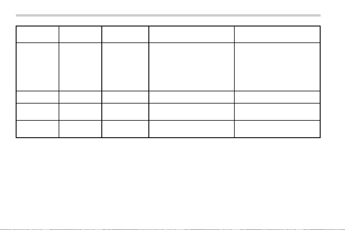
(174,1)
北米Model "A1700BE-B" EDITED: 2017/ 10/ 11
Inside warning
chime
Outside warning
chime
Operation indicator
on push-button igni-
tion switch
Status Action
Long beep
(continuous)
——
Select lever position warning:
. Case 1: The driver’s door was
opened while the push-button igni-
tion switch is in a position other than
“OFF” and the select lever is in a
position other than the “P” position.
. Case 2: The engine is turned off by
pressing the push-button ignition
switch and the select lever is in a
position other than the “P” position.
. Case 1: Shift the select lever to
the “P” position, switch the push-
button ignition switch to “OFF” and
exit the vehicle.
. Case 2: Start the engine, shift
the select lever to the “P” position,
switch the push-button ignition
switch to “OFF” and exit the vehicle.
Ding ——The battery of the access key fob is low.
Replace the battery of the access key
fob.
Ding —
Flashes in green
(15 seconds max.)
Steering lock warning:
The engine start procedure was per-
formed, but the steering is still locked.
While turning the steering wheel right and
left lightly, depress the brake pedal and
press the push-button ignition switch.
Ding — Flashes in orange
System malfunction warning:
A malfunction was detected in the power
system or steering lock.
Contact a SUBARU dealer immediately
and have the vehicle inspected.
NOTE
An electronic chirp will sound while the select lever is in the “R” position. In this case, the select lever position warning chime
will not sound.
Instruments and controls/Warning and indicator lights
3-32
(175,1)
北米Model "A1700BE-B" EDITED: 2017/ 10/ 11
& Security indicator light
This indicator light shows the status of the
alarm system. It also indicates operation of
the immobilizer system.
! Alarm system
It blinks to show the driver the operational
status of the alarm system. For detailed
information, refer to “Alarm system” F2-
24.
! Immobilizer system
The security indicator light starts blinking
in the following conditions.
For models with “keyless access with
push-button start system”:
. Immediately after turning the push-
button ignition switch to the “OFF” position.
. Immediately after opening or closing
the driver’s door when all of the following
conditions are met.
– The push-button ignition switch is in
the “ON” or “ACC” position.
– The access key fob is outside the
vehicle.
– The engine is not running.
– In the event that an unauthorized
key is used (for example, the key is
unregistered or the ID code does not
match), the power is not switched to
“ON” and the security indicator light
continues blinking.
For models without “keyless access
with push-button start system”:
. Approximately 60 seconds after turning
the ignition switch from the “ON” position to
the “ACC” or “LOCK” position.
. Immediately after pulling out the key.
If the indicator light does not blink in the
above conditions , it may indicate that
immobilizer system may be malfunction-
ing. Contact your nearest SUBARU dealer
immediately.
In the event that an unauthorized key (for
example, an unauthorized duplicate) is
used, the security indicator light illumi-
nates. For details about the immobilizer
system, refer to “Immobilizer ” F2-22.
NOTE
. The security indicator light remains
off in the following conditions. It means
that the matching of the ID code is
completed and the immobilizer system
is deactivated, and it does not indicate
a malfunction.
Models with “keyless access with
push-button start system”:
– while the engine is running
– the push-button ignition switch
has been turned to the “ON” or
“ACC ” position and the driver’s
door has not been opened or closed
Models without “keyless access
with push-button start system”:
– while the engine is running
– for approximately 60 seconds
after the ignition switch is turned
from the “ON” position to the “ACC”
or “LOCK” position
– when the ignition switch is in the
“ON” position.
. Even if a malfunction occurs, such
as the security indicator light flashes
irregularly, it will not affect the func-
tionality of the immobilizer system.
– CONTINUED –
Instruments and controls/Warning and indicator lights
3-33
3
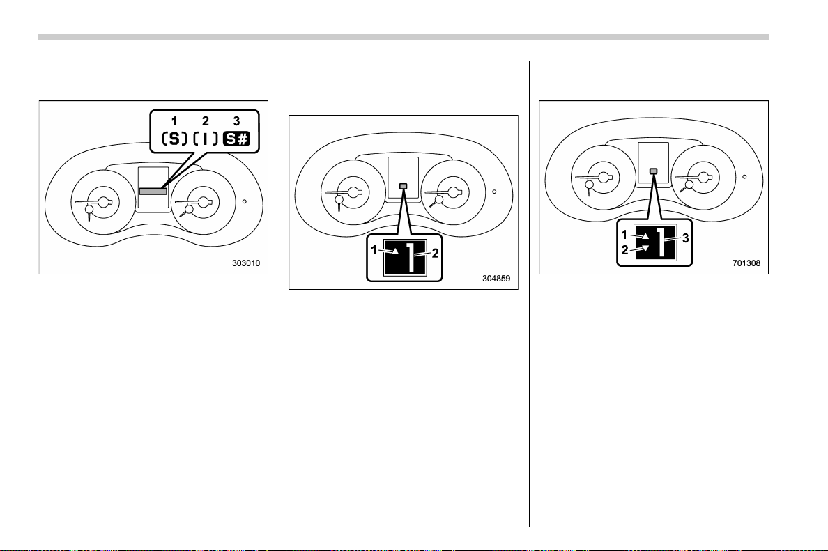
(176,1)
北米Model "A1700BE-B" EDITED: 2017/ 10/ 11
& SI-DRIVE indicator (if
equipped)
1) Sport (S) mode
2) Intelligent (I) mode
3) Sport Sharp (S#) mode
This indicator shows the current SI-DRIVE
mode.
For details of SI-DRIVE mode, refer to “SI-
DRIVE” F7-28.
& Gear position indicator (MT
models)/Shift-up indicator
(STI)
1) Shift-up indicator (STI)
2) Gear position indicator
The gear position indicator shows the
position of the shift lever.
While driving, the shift-up indicator ap-
pears and informs the driver about the
upshift timing for fuel-efficient driving.
The shift-up indicator can be activated or
deactivated.
Refer to “Gear Position Indicator Setting
(MT models)” F3-43.
& Select lever/gear position in-
dicator (CVT models)
1) Upshift indicator
2) Downshift indicator
3) Select lever/gear position indicator
This indicator shows the position of the
select lever.
When the manual mode is selected, the
gear position indicator (which shows the
current gear selection) and the upshift/
downshift indicator light up. Refer to
“Continuously variable transmission” F7-
23.
While the Sport Sharp (S#) mode is
selected, the select lever/gear position
indicator remains on and the upshift/
downshift indicators is off. However, while
Instruments and controls/Warning and indicator lights
3-34
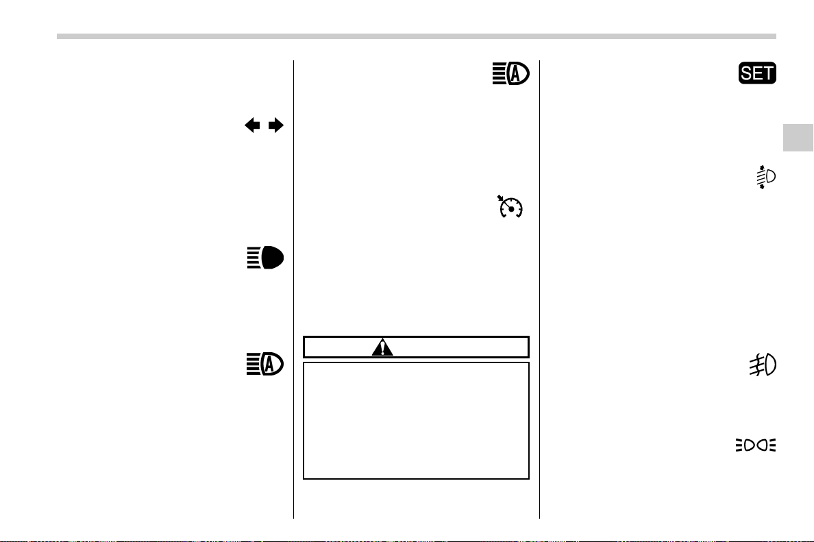
(177,1)
北米Model "A1700BE-B" EDITED: 2017/ 10/ 11
using the manual mode with the Sport
Sharp (S#) mode selected, the upshift/
downshift indicators will be on.
& Turn signal indicator
lights
These lights show the operation of the turn
signal or lane change signal.
If the indicator lights do not blink or blink
rapidly, the turn signal bulb may be burned
out. Replace the bulb as soon as possible.
Refer to “Replacing bulbs” F11-44.
& High beam indicator
light
This light shows that the headlights are in
the high beam mode.
This indicator light also illuminates when
the headlight flasher is operated.
& High Beam Assist indi-
cator light (green) (if
equipped)
This light illuminates when the High Beam
Assist function is activated. For details
about the High Beam Assist function, refer
to “High beam assist function (models with
the EyeSight system)” F3-65.
& High Beam Assist
warning indicator
(yellow) (if equipped)
This warning indicator appears when the
High Beam Assist function malfunctions.
When this warning indicator appears, have
your vehicle inspected by your SUBARU
dealer.
& Cruise control indicator
This indicator appears when the cruise
control main button is pressed to activate
the cruise control function. For details,
refer to “To set cruise control” F7-54.
If this light blinks, do not use the cruise
control. In addition, if it blinks frequently,
contact your SUBARU dealer for an
inspection.
CAUTION
If the CHECK ENGINE warning light/
malfunction indicator light illumi-
nates, the cruise control indicator
flashes at the same time. At this
time, avoid driving at high speed and
have your vehicle inspected at a
SUBARU dealer as soon as possi-
ble.
& Cruise control set indi-
cator
This indicator appears when vehicle speed
has been set to use the cruise control
function. Refer to “To set cruise control”
F7-54.
& Automatic headlight
beam leveler warning
light (models with LED
headlights)
This light illuminates when the automatic
headlight beam leveler does not operate
normally.
If this light illuminates while driving or does
not turn off approximately 3 seconds after
turning the ignition switch to the “ON”
position, have your vehicle inspected at
your SUBARU dealer.
& Front fog light indicator
light (if equipped)
This indicator light illuminates while the
front fog lights are illuminated.
& Headlight indicator
light
This indicator light illuminates under the
following conditions.
– CONTINUED –
Instruments and controls/Warning and indicator lights
3-35
3
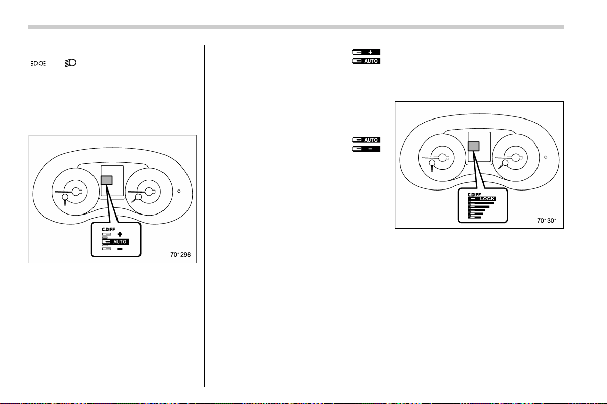
(178,1)
北米Model "A1700BE-B" EDITED: 2017/ 10/ 11
. when the light switch is turned to the
“
” or “ ” position
. when the light control switch is in the
“AUTO” position and the headlights illumi-
nate automatically
& Driver’s control center differ-
ential auto indicator (STI)
This indicator functions while the ignition
switch is “ON”. When it appears, it indi-
cates that the driver ’s control center
differential is set to the auto mode. It
disappears when the driver’s control cen-
ter differential is set to the manual mode.
For details, ref er to “Driver’sControl
Center Differential (C.DIFF/DCCD) (STI)”
F7-18.
! Driver’s control center dif-
ferential auto [+] indicator
(STI)
When the AUTO [+] mode is set, the AUTO
[+] indicator appears.
For details, re fer to “Driver’s Con trol
Center Differential (C.DIFF/DCCD) (STI)”
F7-18.
! Driver’s control center dif-
ferential auto [−] indicator
(STI)
When the AUTO [−] mode is set, the AUTO
[−] indicator appears.
For details, re fer to “Driver’s Con trol
Center Differential (C.DIFF/DCCD) (STI)”
F7-18.
& Driver’s control center differ-
ential indicator and warning
(STI)
! Indicator
When you select the manual mode of the
driver’s control center differential, these
indicators will appear. They indicate the
initial limited slip differential (LSD) torque
that is currently selected for the center
differential.
Instruments and controls/Warning and indicator lights
3-36
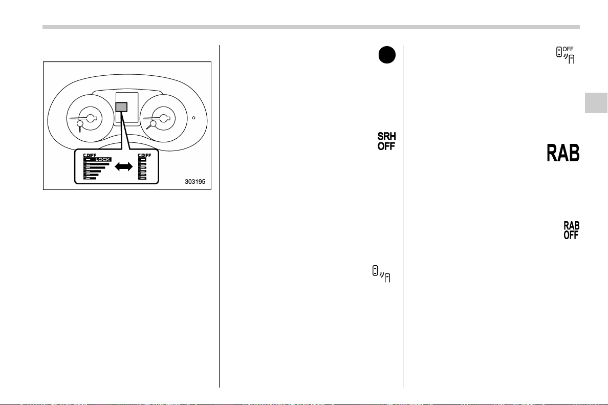
(179,1)
北米Model "A1700BE-B" EDITED: 2017/ 10/ 11
! Warning indicator
All the indicators wi ll flash when the
driver’s control center differential has a
malfunction. Have the vehicle inspected
by your SUBARU dealer. For details, refer
to “Driver’s Control Center Differential (C.
DIFF/DCCD) (STI)” F7-18.
If a malfunction occurs in the vehicle (for
example, when the rear differential oil
becomes hot), all of the indicators may
disappear. In this case, the setting value
for the initial limited slip differential (LSD)
torque of the driver’s control center differ-
ential (C.DIFF/DCCD) will be cancelled.
However, it does not indicate a malfunction
of the C.DIFF/DCCD itself.
& REV indicator light (STI)
This indicator light illuminates when the
engine speed reaches the level that was
previously set. This indicator light also
flashes when the tachometer needle en-
ters the red zone. For details, refer to “REV
indicator light and buzzer (STI)” F3-12.
& Steering Responsive
Headlight warning indi-
cator/Steering Respon-
sive Headlight OFF indi-
cator (if equipped)
This indicator appears when the Steering
Responsive Headlight is deactivated.
Also, the indicator flashes when a mal-
function occurs in the Steering Respon-
sive Headlight. Refer to “Steering Respon-
sive Headlight (SRH)” F3-69.
& BSD/RCTA warning in-
dicator (if equipped)
This warning indicator appears when the
BSD/RCTA is malfunctioning. In this case
the BSD/RCTA warning indicator will be
shown on the combination meter display
(color LCD). When this indicator appears,
have your vehicle inspected by your
SUBARU dealer as soon as possible.
& BSD/RCTA OFF indica-
tor (if equipped)
The indicator appears whe n the BSD/
RCTA is deactivated. In this case the
BSD/RCTA OFF indicator will be shown
on the combination meter display (color
LCD). For details, refer to “BSD/RCTA”
F7-57.
& RAB warning
indicator (if equipped)
This indicator illuminates if the Reverse
Automatic Braking System malfunctions.
Refer to “Reverse Automatic Braking
System” F7-66.
& RAB OFF indicator light
(if equipped)
This indicator illuminates when the Re-
verse Automatic Braking System is turned
OFF, or when the Reverse Automatic
Braking System is suspended temporarily.
Refer to “Reverse Automatic Braking
System” F7-66.
Instruments and controls/Warning and indicator lights
3-37
3
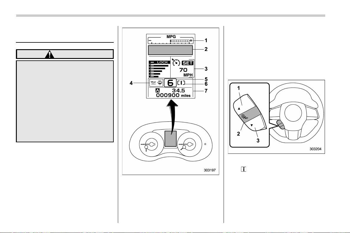
(180,1)
北米Model "A1700BE-B" EDITED: 2017/ 10/ 11
Combination meter display
(color LCD)
WARNING
Always pay adequate attention to
safe driving when operating the
combinatio n meter display (color
LCD) while the vehicle is in motion.
When operation of the combination
meter display (color LCD) interferes
with your ability to concentrate on
driving, stop t he vehicle before
performing operations on the
screen. Also, do not concentrate on
the display while driving. Doing so
may cause you to look away from the
road and could result in an accident.
Various information will be shown on the
combination meter display (color LCD).
Also, a warning message will appear on
the di splay if a mal function, etc. is
detected. In addition, several settings for
the displayed content can be performed.
Combination meter display (color LCD)
1) ECO gauge (refer to “ECO gauge” F3-
12.)
2) Warning screen (refer to “Warning
screen” F3-39.)/Basic screen (refer to
“Basic screens” F3-40.)
3) Cruise control information display/
C.DIFF/DCCD indicator
4) Warning indication (refer to “Warning
indication” F3-41.)
5) Select lever/gear position indicator (refer
to “Select lever/gear position indicator
(CVT models)” F3-34.)
6) SI-DRIVE indicator light (refer to “SI-
DRIVE indicator” F3-34.)
7) Odometer (refer to “Odometer” F3-9.)/
double trip meter (refer to “Double trip
meter” F3-9.)
Control switch
1) Up (select)
2)
/SET (enter)
3) Down (select)
Instruments and controls/Combination meter display (color LCD)
3-38
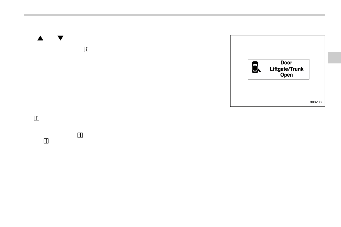
(181,1)
北米Model "A1700BE-B" EDITED: 2017/ 10/ 11
& Basic operation
Pull “ ” or “ ” of the control switch
toward you to switch the screens and
selection items. Pull the “
/SET” switch
toward you to select and set the item.
If there are some useful messages, such
as vehicle information, warning informa-
tion, etc., they will interrupt the current
screen, and appear on the display accom-
panied by a beep. If such a screen is
displayed, take proper action according to
the message shown on the screen.
The warning sc reen will return to the
original screen after a few seconds. While
the “
” information reminder is shown on
the display, it may be possible to display
the warning screen again. To recall the
message marked with “
” on the display,
pull the “
/SET” switch toward you.
& Welcome screen (opening
animation) and Good-bye
screen (ending animation)
When the driver’s door is opened and
closed after unlocking the door, the Wel-
come screen (opening animation) will
appear on the combination meter display
(color LCD) for approximately 20 seconds.
When the ignition switch is turned to the
“LOCK”/“OFF” position, the combination
meter display (color LCD) gradually turns
off while showing the Good-bye screen
(ending animation).
NOTE
. The welcome screen and the good-
bye screen may differ in the actual
words and appearance.
. Once the Welcome screen appears,
it takes a certain pe riod of time to
display it again.
. The Welcome screen will disappear
after turning the ignition switch to the
“ON” position whi le the Welcome
screen is displayed.
. If you open any of the doors while
the Welcome screen is displayed, the
door ajar warning will appear.
. You can set the Welcome screen and
Good-byescreentoonoroff.For
details, refer to “Welcome Good-bye
Screen” F3-43.
& Warning screen
Example of warning
If a warning or a malfunction is detected, a
message will appear. Take the appropriate
actions based on the messages indicated.
– CONTINUED –
Instruments and controls/Combination meter display (color LCD)
3-39
3
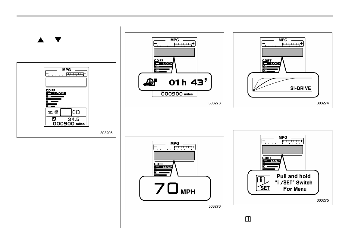
(182,1)
北米Model "A1700BE-B" EDITED: 2017/ 10/ 11
& Basic screens
Pull the “ ” or “ ” switch on the steering
wheel to change the screen that is always
displayed.
Default screen:
Journey time screen:
This screen displays the journey time (the
time that has elapsed since the ignition
switch was turned to the “ON” position).
Digital speedometer:
SI-DRIVE mode screen:
This screen indicates the current SI-
DRIVE mode with its throttle angle.
Menu screen entering screen:
While this screen is selected, pull and hold
the “
/SET” switch to enter the menu
Instruments and controls/Combination meter display (color LCD)
3-40

(183,1)
北米Model "A1700BE-B" EDITED: 2017/ 10/ 11
screen.
& Warning indication
1) Warning indication
When the corresponding situation occurs,
the following warning indications will be
displayed.
Mark Name Page
Engine low oil level
warning indicator
3-17
BSD/RCTA warning in-
dicator (if equipped)
3-37
BSD/RCTA OFF indi-
cator (if equipped)
3-37
Steering Responsive
Headlight OFF indicator
(if equipped)
3-37
High beam assist warn-
ing indicator (yellow)
3-35
Windshield washer fluid
warning indicator
3-18,
3-74,
11-38
Access key warning in-
dicator (if equipped)
3-28
RAB warning indicator
(if equipped)
3-37
RAB OFF indicator (if
equipped)
3-37
& Menu screens
Pull and hold the “ /SET” switch to enter
the menu screens when all of the following
conditions are satisfied.
. The vehicle has been completely
stopped.
. The select lever is in the “P” position
(CVT models).
. The shift lever is in the neutral position
(MT models).
. The menu screen entering screen is
selected.
Pull the “
” or “ ” switch to select the
menu. Pull the “
/SET” switch to enter the
selected menu.
NOTE
If you enter the “Go Back” menu, the
system will return to the previous
screen.
– CONTINUED –
Instruments and controls/Combination meter display (color LCD)
3-41
3
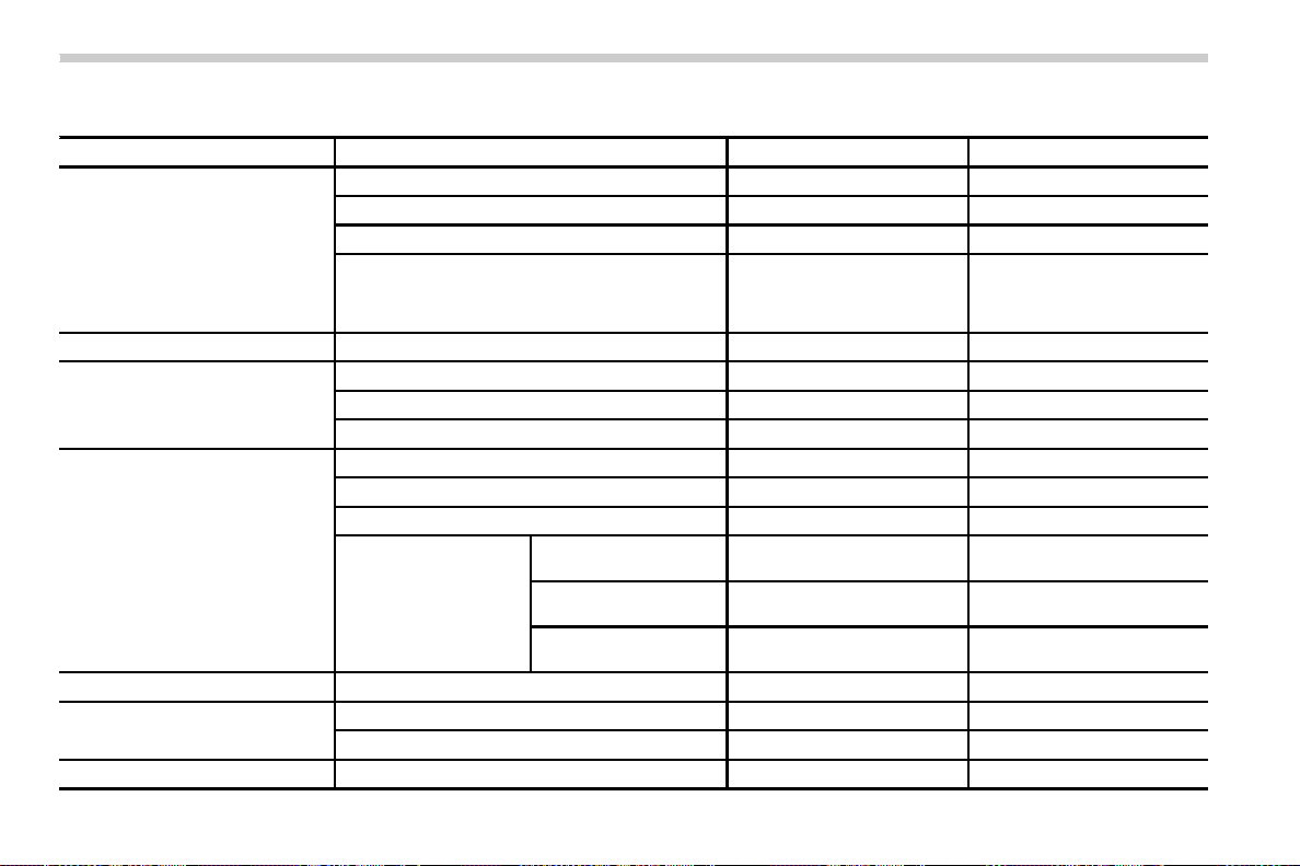
(184,1)
北米Model "A1700BE-B" EDITED: 2017/ 10/ 11
The menu list is as follows.
Top menu Menu option Possible settings Initial settings
Screen Settings Welcome Good-bye Screen On or Off On
Gauge Initial Movement On or Off On
Gear Position Indicator Setting (MT models) On or Off On
Languages Select the display language. The default language settings
vary depending on individual
countries. (For U.S. models:
English)
SRH (if equipped) ― On or Off On
REV settings (STI) REV Indicator Light On or Off Off
REV Alarm Level Engine Speed 2000 rpm - RED ZONE 2000 rpm
REV Buzzer On or Off Off
EyeSight (models with the
EyeSight system)
Warning Volume Max/Mid/Min Mid
Lead Vehicle Acquisition Sound On or Off On
Lead Vehicle Moving Monitor Function On or Off On
EyeSight Assist Monitor EyeSight Assist Monitor
Red indicator
On or Off On
EyeSight Assist Monitor
Yellow indicator
On or Off On
EyeSight Assist Monitor
Green indicator
On or Off On
BSD/RCTA (if equipped)
Warning Volume Max/Mid/Min/OFF Mid
RAB (models with the EyeSight
system)
Warning Volume Max/Mid/Min Mid
Sonar Audible Alarm On or Off On
Default Settings
― Yes or No ―
Instruments and controls/Combination meter display (color LCD)
3-42
(185,1)
北米Model "A1700BE-B" EDITED: 2017/ 10/ 11
! Screen Settings
After entering the “Screen Settings” menu,
select one of the following menus.
! Welcome Good-bye Screen
The welcome screen/good-bye screens
can be activated or deactivated. Select
“On” to activate the screens. Select “Off” to
deactivate the screens.
! Gauge Initial Movement
The movement of the meter needles and
gauge needles that occurs when the
ignition switch is turned to the “ON”
position can be activated or deactivated.
Select “On” to activate. Select “Off” to
deactivate.
! Gear Position Indicator Setting
(MT models)
Display of the shift position indicator can
be activated or deactivated. Select “On” to
activate display of the shift position in-
dicator or “Off” to deactivate it.
! Languages
Operate the “
” or “ ” switch on the
steering wheel to display the preferred
language. Then pull the “
/SET” switch to
select the displayed language.
! SRH (if equipped)
Select “On” to activate the Steering Re-
sponsive Headlight (SRH). Select “Off” to
deactivate the SRH.
! REV settings (STI)
NOTE
If the setting of the REV Indicator Light
is “Off”, the setting menus of the REV
Alarm Level Engine Speed and the REV
Buzzer are not displayed.
After entering the “REV settings” menu,
select any of the following menus.
! REV Indicator Light
Display of the REV indicator light can be
activated or deactivated. Select “On” to
activate display of the REV indicator light
or “Off” to deactivate it.
! REV Alarm Level Engine Speed
The alarm-level engine speed can be set
(in 100 rpm steps) within the range from
2,000 rpm to the red zone.
! REV Buzzer
The REV buzzer can be activated or
deactivated. Select “On” to activate the
REV buzzer or “Off” to deactivate it.
! EyeSight (models with the EyeSight
system)
NOTE
Refer to the Owner’s Manual supple-
ment for the EyeSight system.
! BSD/RCTA (if equipped)
After entering the “BSD/RC TA” menu,
select the “Warning Volume” menu. You
can set the volume of the warning buzzer
for RCTA (Rear Cross Traffic Alert). You
can select “Max”, “Mid”, “Min” or “Off”.
! RAB (models with the EyeSight
system)
After entering the “RAB” menu, select one
of the following menus.
NOTE
For details about the Reverse Auto-
matic Braking system, refer to “Re-
verse Automatic Braking System” F7-
66.
! Warning Volume
The volume of the warning sound that is
activated when the Reverse Automatic
Braking system is in operation can be set
in 3 stages (“ Max”, “Mid” and “Min”).
– CONTINUED –
Instruments and controls/Combination meter display (color LCD)
3-43
3
(186,1)
北米Model "A1700BE-B" EDITED: 2017/ 10/ 11
! Sonar Audible Alarm
The Reverse Automatic Braking system is
equipped with a function that emits a
warning sound when the system operates.
The function can be activated or deacti-
vated. Select “ On” to set the warning
sound to active. Select “Off” to set the
warning sound to inactive.
! Default Settings
Select “Yes” to use the menu screen to
restore customized settings to the factory
default settings. Select “No” to return to the
previous screen without restoring to the
factory default settings.
Multi-function display (color
LCD)
WARNING
Always pay adequate attention to
safe driving when operating the
multi-function display while the ve-
hicle is in motion. When operation of
the multi-function display is disturb-
ing your awareness and ability to
concentrate on driving, stop the
vehicle in a safe place before per-
forming operations on the screen.
Also, do not concentrate on the
display while driving. Doing so may
cause you to look away from the
road and could result in an accident.
The multi-function display has the follow-
ing functions.
Description Page
Displays useful messages,
such as warning information,
etc.
3-46
Displays basic screens (e.g.
fuel consumption screen, etc.)
3-47
Sets and adjusts maintenance
notification
3-59
Registers driving history 3-60
Sets and customizes car op-
eration
3-61
Reverse Automatic Braking
system (if equipped)
7-66
Also, use the multi-function display to set
and initialize the multi-function display
itself.
NOTE
. Illustrations show the display for
U.S.-spec. models as an example. For
models other than U.S.-spec. models,
elements in the illustrations (such as
the display indication and measure-
ment unit) may be different than the
ones for U.S.-spec. models.
. When the vehicle is in motion,
certain functions and selections may
not be available.
. The images shown in this Owner’s
Manual are sample images. The actual
images may vary depending on the
Instruments and controls/Multi-function display (color LCD)
3-44
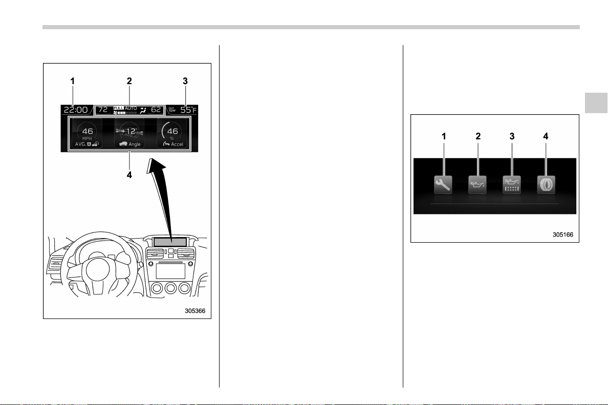
(187,1)
北米Model "A1700BE-B" EDITED: 2017/ 10/ 11
market and vehicle specifications.
Multi-function display
1) Clock
2) Climate control (displayed only when the
ignition switch is in the “ ON” position)
3) Outside temperature
4) Information screen
NOTE
The outside temperature indicator
shows the temperature around the
sensor. Therefore, the temperature in-
dication may differ from the actual
outside air temperature.
& Welcome screen
When the driver’s door is closed, the
welcome screen will appear for a short
time.
NOTE
. The welcome screen will disappear
when the ignition switch is turned to the
“ON” positi on while the welcome
screen is displayed.
. You can set the welcome screen to
on or off. For details, refer to “Bypass
screen setting” F3-58.
. For a certain period of time after the
welcome screen has once appeared, it
may not appear again even when the
driver’s door is closed again. This does
not indicate a malfunction.
& Self-check screen
When the ignition switch is turned to the
“ON” position, the vehicle self-check will
be performed. The screens corresponding
to the following items will appear one after
another for several seconds each.
1) Inspection and maintenance: Checks the
interval of inspection and maintenance.
2) Engine oil: Checks the interval of engine
oil replacement.
3) Oil filter: Checks the interval of oil filter
replacement.
4) Tires: Checks the interval of tire rotation.
When the checks are performed, the color
of the icon corresponding to the checked
item will turn as follows:
. If the checked item has no notifications,
it turns green.
. If the checked item has any mainte-
– CONTINUED –
Instruments and controls/Multi-function display (color LCD)
3-45
3
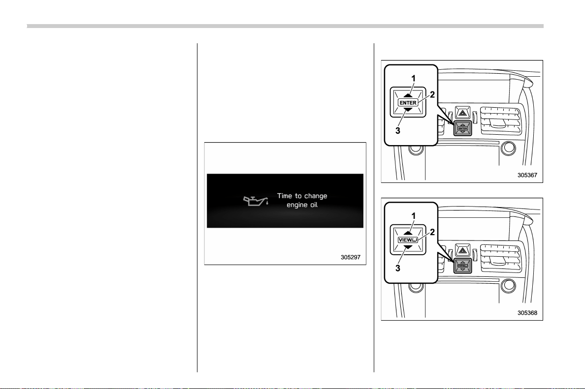
(188,1)
北米Model "A1700BE-B" EDITED: 2017/ 10/ 11
nance notifications, it turns yellow.
If there is a notification, the message will
be displayed. Take the appropriate actions
based on the message indicated.
NOTE
. You can set the self-check screen to
on or off. The default setting is off. For
details, refer to “On/Off setting” F3-59.
. After performing the maintenance,
change the setting of the correspond-
ing maintenance item. For details, refer
to “Maintenance settings” F3-59.
. The maintenance notification screen
will be displayed under either of the
following conditions.
– The period of time remaining until
the registered notification date is 15
days or less.
– The total driving distance remain-
ing until the registered notification
distance is approximately 311 miles
(500 km) or less.
. The maintenance notification screen
will be displayed until either of the
following conditions is satisfied.
– The period of time passed after
the registered notification date is 15
days or more.
– The total distance driven after the
registered notification distance is
approximately 311 miles (500 km) or
more.
& Interruption screen
Useful messages, such as reminder in-
formation, vehicle i nforma tion, warning
information, etc. may interrupt the current
screen and appear on the display accom-
panied by a beep. Take proper action
according to the message.
The warning screen will ret urn to the
original screen after a few seconds.
& Basic operation
Control switch (type A)
Control switch (type B)
1) Up (select)
2) ENTER (push)
3) Down (select)
Instruments and controls/Multi-function display (color LCD)
3-46
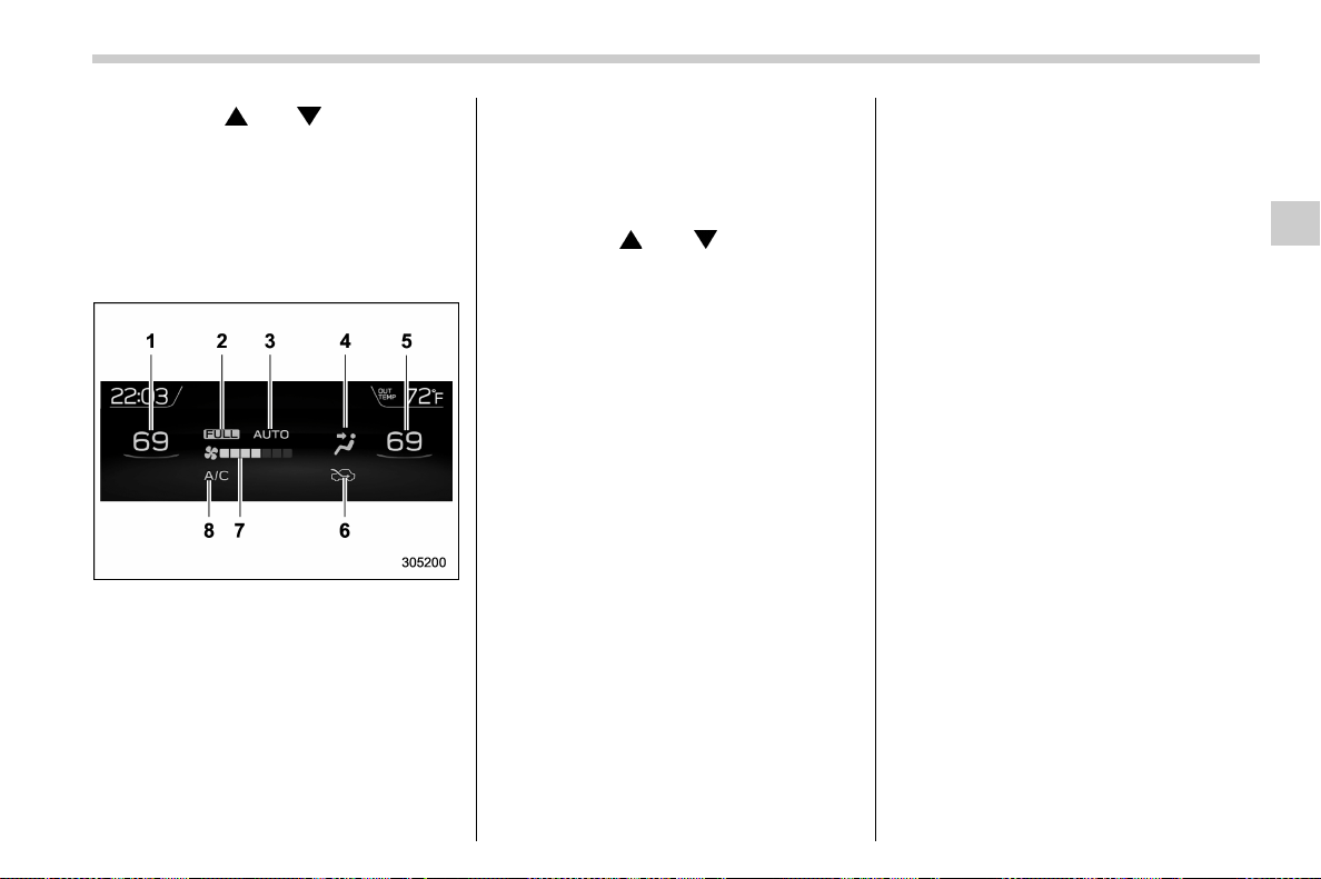
(189,1)
北米Model "A1700BE-B" EDITED: 2017/ 10/ 11
By operating “ ” or “ ” of the control
switch, the screens and selection items
can be switched. When the ENTER button
is pushed, the item can be selected and
set.
& Basic screens
! Climate control screen
Climate control screen
1) Set temperature indicator (left-hand side)
2) FULL AUTO indicator
3) AUTO indicator
4) Airflow mode indicator
5) Set temperature indicator (right-hand
side)
6) Air inlet selection indicator
7) Fan speed indicator
8) Air conditioner ON indicator
When operating the climate control sys-
tem, the basic screen will change to the
climate control screen. For details about
the climate control system, refer to “Cli-
mate control” F4-1.
! Information screen
Operate the “
” or “ ” of the control
switch to select the screen that is always
displayed on.
– CONTINUED –
Instruments and controls/Multi-function display (color LCD)
3-47
3
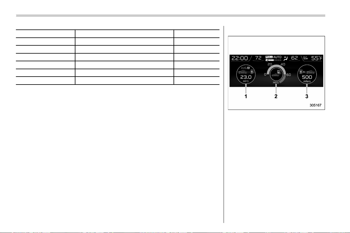
(190,1)
北米Model "A1700BE-B" EDITED: 2017/ 10/ 11
Content Description Page
Fuel consumption screen Displays fuel consumption screen. 3-48
Triple meter screen Displays up to 3 optional items. 3-49
Prevention safety screen Displays the status of your vehicle. 3-49
Boost pressure screen Displays the boost pressure, etc. 3-50
Guidance screen Enters the setting screen 3-50
Clock/calendar screen Displays the clock/calendar.
3-51
! Fuel consumption screen
1) Average fuel consumption corresponding
to the driving distance of each trip meter
2) Current fuel consumption
3) Driving range on remaining fuel
NOTE
The driving range on the remaining fuel
is only a guide. The indicated value may
differ from the actual driving range on
the remaining fuel, so you must im-
mediately fill the tank when the low fuel
warning light illuminates.
Instruments and controls/Multi-function display (color LCD)
3-48

(191,1)
北米Model "A1700BE-B" EDITED: 2017/ 10/ 11
! Triple meter screen
Triple meter screen (display example)
From the following pieces of information,
you can select up to three items to be
displayed.
Item Details
Engine oil temperature (except
STI)
Average vehicle speed
Accelerator opening ratio
Item Details
Vehicle posture
Average fuel consumption cor-
responding to the driving dis-
tance of the odometer
Boost pressure
Journey distance (the distance
that has been driven since the
ignition switch was turned to
the “ON” position)
Average fuel consumption for
the entire driving distance from
when the ignition switch was
turned to the “ON” position
! Prevention safety screen
1) Telltale screen
2) Steering angle
3) Vehicle posture
4) Running condition
For functions that are operating, the
corresponding indicator will illuminate or
flash.
NOTE
The vehicle posture indication may
differ from the actual vehicle posture.
– CONTINUED –
Instruments and controls/Multi-function display (color LCD)
3-49
3
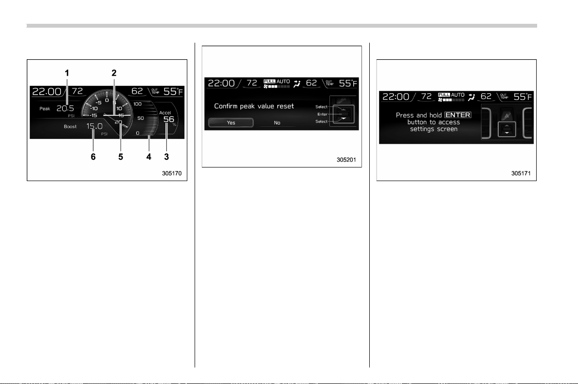
(192,1)
北米Model "A1700BE-B" EDITED: 2017/ 10/ 11
! Boost pressure screen
1) The peak value of the boost pressure
(digital display)
2) Boost pressure (analog display)
3) Accelerator opening ratio (digital display)
4) Accelerator opening ratio (analog dis-
play)
5) The peak value of the boost pressure
(analog display)
6) Boost pressure (digital display)
You can reset the peak value of the boost
pressure. Press the ENTER button to
enter the reset screen.
Select “Yes” to reset the peak value.
Select “No” to keep the current park
value.
! Guidance screen
Guidance screen (display example)
Press and hold the ENTER button to enter
the setting screen. For details, refer to
“Setting screen” F3-52.
Instruments and controls/Multi-function display (color LCD)
3-50
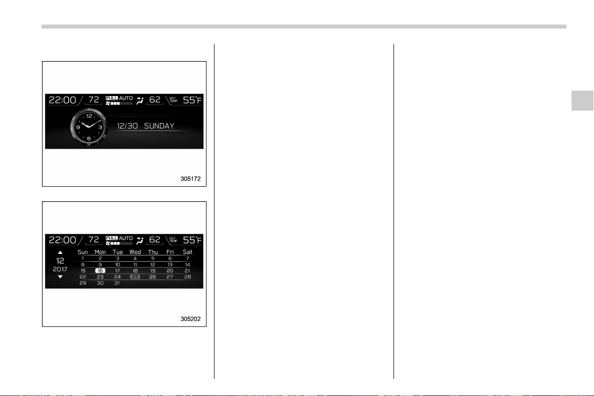
(193,1)
北米Model "A1700BE-B" EDITED: 2017/ 10/ 11
! Clock/calendar screen
Clock
Calendar
You can select the clock or calendar to be
displayed. You can also turn the screen off.
For the setting procedure, refer to “Clock
setting” F3-57.
– CONTINUED –
Instruments and controls/Multi-function display (color LCD)
3-51
3

(194,1)
北米Model "A1700BE-B" EDITED: 2017/ 10/ 11
& Setting screen
Push and hold the ENTER button to display the setting screen. Select the preferred menu by operating the “ ” or “ ” switch.
Top menu Menu option Description Page
Time/Date
Date Set and adjust the date. 12h or 24h format can be selected. 3-55
Birthday Set a birthday. (max. 5) 3-55
Anniversary Set an anniversary day. (max. 5) 3-55
Daylight Saving Time Turn the daylight saving time on or off 3-56
Go Back Return to the top menu. —
Display
Contrast Adjust the contrast. +5 ↔ −53-56
Screen Off Turn the screen on or off. On or Off 3-56
Beep Adjust the beep sound volume. High, Low or Off 3-57
Go Back Return to the top menu. —
Screen
Setting
Triple Meter Set and customize the triple meter. 3-57
Clock Select the clock format. Analog Clock, Calendar or Off 3-57
Bypass Screen Set the bypass screen for each item. On or Off 3-58
Languages Select the display language.
English or French or Spanish
(U.S.-spec. models only)
3-58
Camera Shift Link Set the front view monitor On or Off 3-58
Go Back Return to the top menu. —
Instruments and controls/Multi-function display (color LCD)
3-52
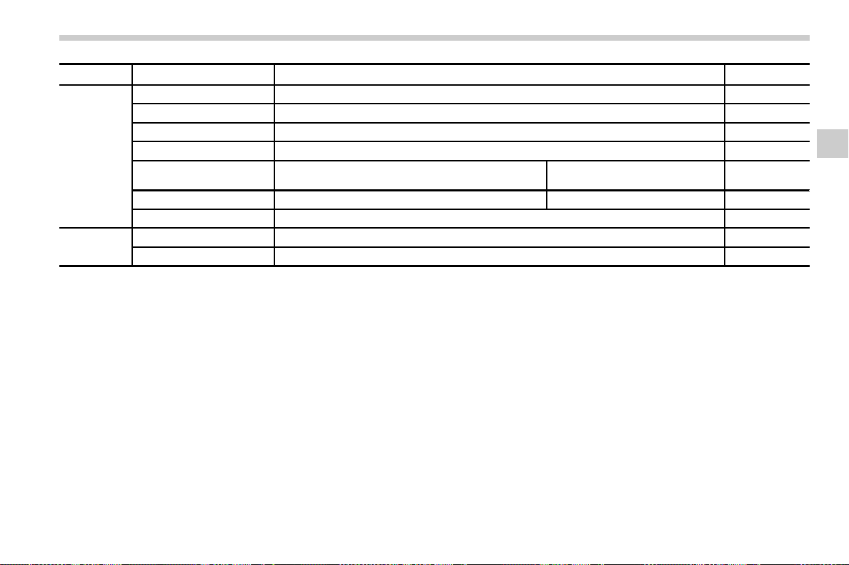
(195,1)
北米Model "A1700BE-B" EDITED: 2017/ 10/ 11
Top menu Menu option Description Page
Mainte-
nance
Maintenance Schedule Set and adjust the vehicle maintenance notification date. 3-59
Engine Oil Set and adjust the oil maintenance notification date. 3-59
Oil Filter Set and adjust the oil filter maintenance notification date. 3-59
Tires Set and adjust the tire maintenance notification date. 3-59
On/Off
Turn on or off the self-check screen that is activated
when the ignition switch is turned to the “ON” position.
On or Off 3-59
Clear All Settings Clear all items to the factory default settings. Yes or No 3-60
Go Back Return to the top menu. —
Driving
History
Set Register and overwrite the driving record. 3-60
Go Back Return to the top menu.
—
– CONTINUED –
Instruments and controls/Multi-function display (color LCD)
3-53
3

(196,1)
北米Model "A1700BE-B" EDITED: 2017/ 10/ 11
Top menu Menu option Description Page
Car Setting
Keyless Buzzer Volume Set the audible signal volume. 0 (OFF) to 7 3-61
Hazard Warning Flasher Set the hazard warning flasher. On or Off 3-61
Defogger Set and customize the operation of the defogger. 15 minutes or Continuous 3-61
Interior Light Set and customize the interior light off delay timer. 10, 20, 30 seconds or Off 3-61
Auto Light Sensor
*1
Set and customize the sensitivity of the auto light
sensor.
Low, Mid, High or Max 3-61
Keyless Access Setting
Driver’s Door Unlock
*1
Set and customize the keyless access function. Driver’s Door Only, All 3-62
Welcome Lighting Set the leaving time and approaching time. 30, 60, 90 seconds or Off 3-62
Go Back Return to top menu. —
Initialize
Reset to Defaults Reset all settings to the default settings. Yes or No 3-62
Lifetime Fuel Cons Reset Clear logged lifetime fuel consumption data. Yes or No 3-62
Go Back Return to the top menu. —
Go Back
— Return to the top menu.
—
*1: If equipped
Instruments and controls/Multi-function display (color LCD)
3-54
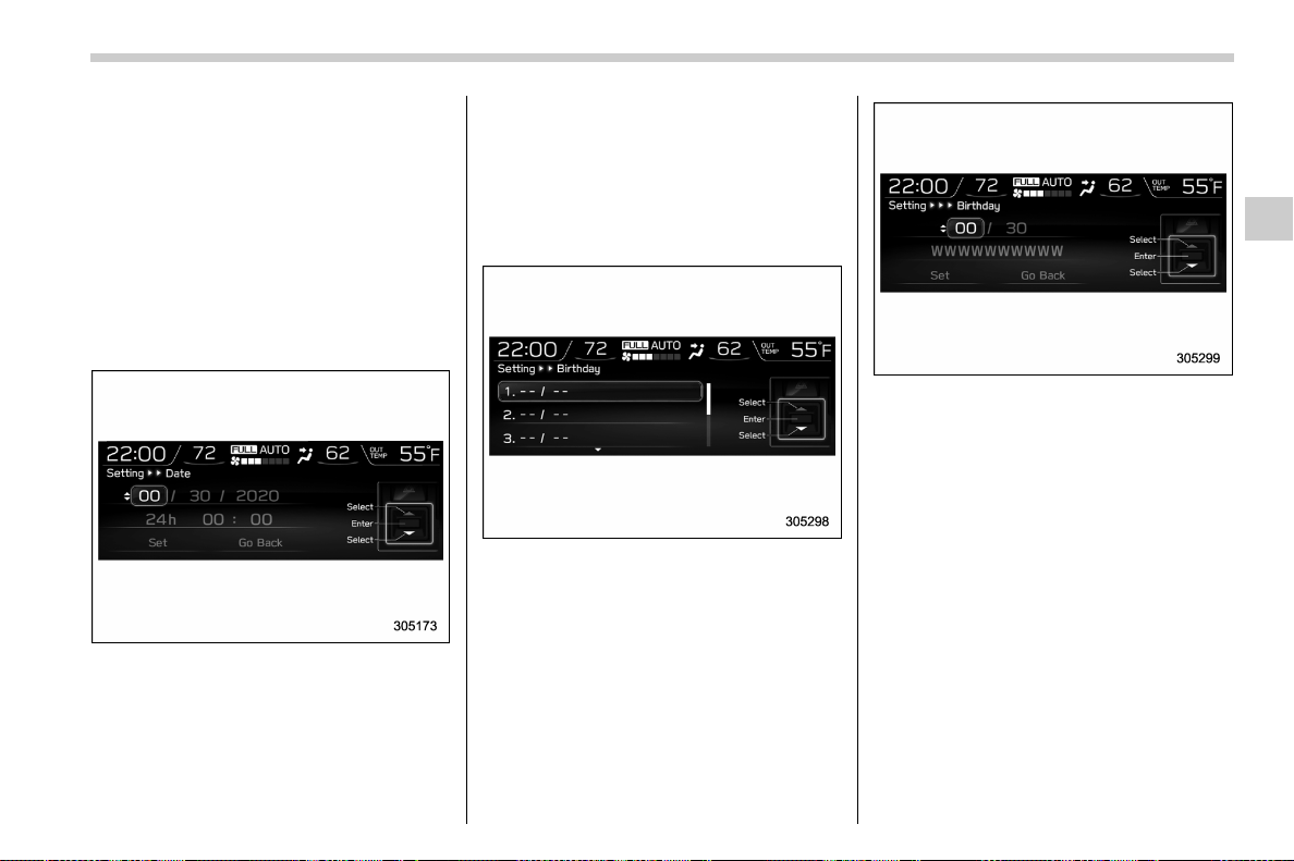
(197,1)
北米Model "A1700BE-B" EDITED: 2017/ 10/ 11
! Date and time settings
If a birthday or anniversary is approaching,
a message will be displayed when turning
the ignition switch to the “ON” position. You
can set this function to on or off. For
details, refer to “Bypass screen setting”
F3-58.
! Current date and time setting
1. Select “Date” from the 2nd menu in the
setting screen. Refer to “Setting screen”
F3-52.
2. Enter the date by using the control
switches.
3. Select 12h or 24h format settings.
4. Enter the time by using the control
switches.
5. Select “Set” to exit settings. Select “Go
Back” to return to the previous screen
without applying the setting changes.
! Birthday setting
1. Select “Birthday” from the 2nd menu
in the setting screen. Refer to “Setting
screen” F3-52.
2. Select from the list the number that you
want to register.
3. Enter the date and the text by using the
control switches.
4. Select “Set” to exit settings. Select “Go
Back” to return to the previous screen
without applying the setting changes.
NOTE
You can store a maximum of 5 birth-
days.
! Anniversary setting
The setting procedure is the same as
“Birthday setting” F3-55, but select the
“Anniversary” item in step 1.
NOTE
You can store a maximum of 5 anniver-
saries.
– CONTINUED –
Instruments and controls/Multi-function display (color LCD)
3-55
3
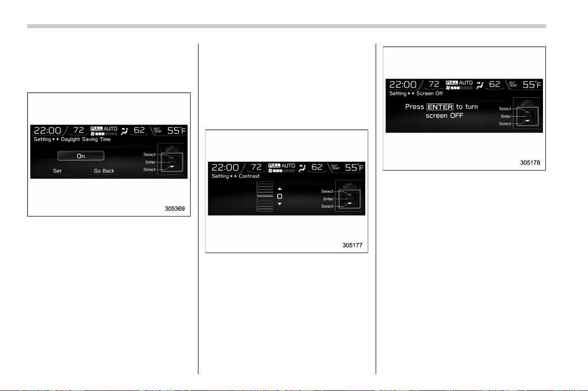
(198,1)
北米Model "A1700BE-B" EDITED: 2017/ 10/ 11
! Daylight saving time setting
1. Select “Daylight Saving Time” from
the 2nd menu in the setting screen. Refer
to “Setting screen” F3-52.
2. Selec t “On” or “Off” by using the
control switches.
3. Select “Set” to exit settings. Select “Go
Back” to return to the previous screen
without applying the setting changes.
! Display/Beep settings
You can set the display settings and
volume settings.
! Contrast setting
1. Select “Contrast” from the 2nd menu
in the setting screen. Refer to “Setting
screen” F3-52.
2. Select the contrast level by using the
control switches.
3. Press the ENTER button to confirm the
setting.
! Screen OFF setting
1. Selec t “Screen Off” from the 2nd
menu in setting screen. Refer to “Setting
screen” F3-52.
2. Press the ENTER button to turn off the
screen.
Restoring the screen
When operating the control switches with
the ignition switch in the “ON” or “ACC”
position, the screen will be restored. The
screen will be restored with the basic
screen that wa s displayed when the
screen was turned off.
NOTE
While the screen is off, the screen
switches to the climate control screen
only when the air conditioner is operat-
ing.
Instruments and controls/Multi-function display (color LCD)
3-56
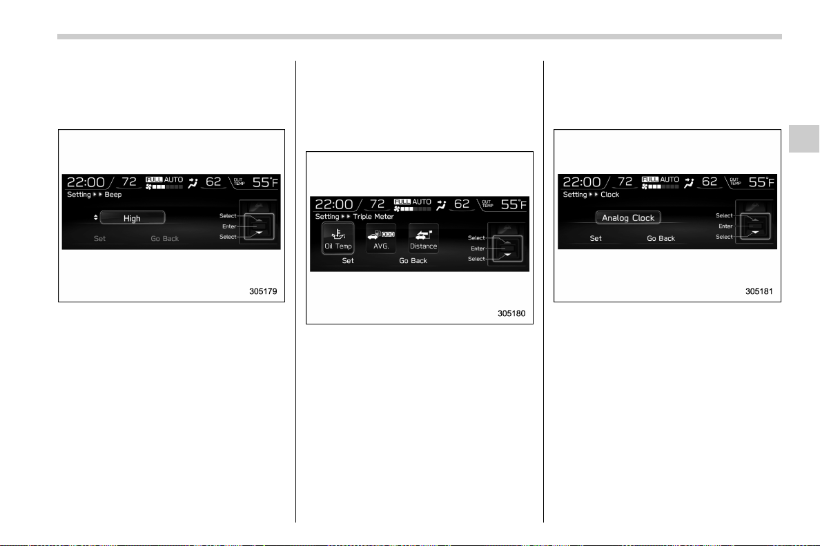
(199,1)
北米Model "A1700BE-B" EDITED: 2017/ 10/ 11
! Beep setting
1. Select “Beep” from the 2nd menu in
the setting screen. Refer to “Setting
screen” F3-52.
2. Set the beep volume by using the
control switches.
3. Select “Set” to exit settings. Select “Go
Back” to return to the previous screen
without applying the setting changes.
! Screen settings
! Triple meter setting
1. Select the “Triple Meter” from the 2nd
menu in setting screen. Refer to “Setting
screen” F3-52.
2. Set the desired items by using the
control switches. For details about items,
refer to “Triple meter screen” F3-49.
3. Select “Set” to exit settings. Select “Go
Back” to return to the previous screen
without applying the setting changes.
NOTE
. You can display a maximum of the 3
items.
. The same item cannot be selected
for the left, center or right location.
! Clock setting
1. Select “Clock” from the 2nd menu in
the setting screen. Refer to “Setting
screen” F3-52.
2. Select “Analog Clock”, “Calendar” or
“Off” by using the control switches.
3. Select “Set” to exit settings. Select “Go
Back” to return to the previous screen
without applying the setting changes.
– CONTINUED –
Instruments and controls/Multi-function display (color LCD)
3-57
3
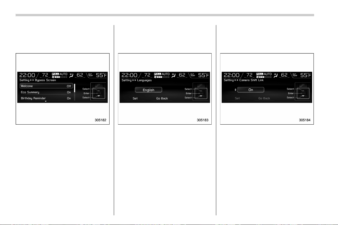
(200,1)
北米Model "A1700BE-B" EDITED: 2017/ 10/ 11
! Bypass screen setting
1. Select “Bypass Screen” from the 2nd
menu in the setting screen. Refer to
“Setting screen” F3-52.
2. Select “On” or “Off” to turn the display
of items on or off by using the control
switches.
3. Select “Set” to exit settings. Select “Go
Back” to return to the previous screen
without applying the setting changes.
! Language setting
1. Sele ct “Languages” from the 2nd
menu in the setting screen. Refer to
“Setting screen” F3-52.
2. Select the preferred language by using
the control switches.
3. Select “Set” to exit settings. Select “Go
Back” to return to the previous screen
without applying the setting changes.
! Camera shift link setting
1. Select “Camera Shift Link” from the
2nd menu in the setting screen. Refer to
“Setting screen” F3-52.
2. Select “On” or “Off” by using the
control switches.
3. Select “Set” to exit settings. Select “Go
Back” to return to the previous screen
without applying the setting changes.
Instruments and controls/Multi-function display (color LCD)
3-58
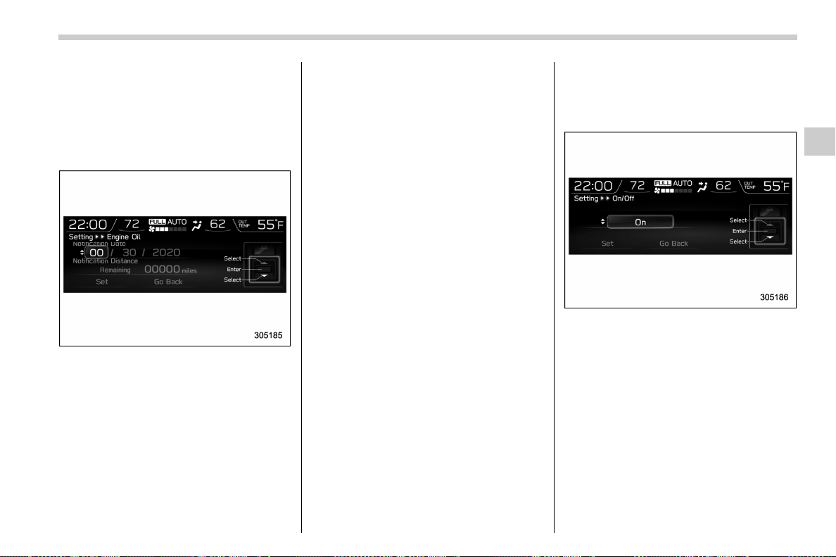
(201,1)
北米Model "A1700BE-B" EDITED: 2017/ 10/ 11
! Maintenance settings
You can set maintenance reminders.
! Engine oil setting
1. Select “Engine Oil” from the 2nd menu
in the setting screen. Refer to “Setting
screen” F3-52.
2. Set the date and distance of the
reminder by using the control switches.
3. Select “Set” to exit settings. Select “Go
Back” to return to the previous screen
without applying the setting changes.
NOTE
. The reminder will be displayed by
either date or distance in accordance
with the setting.
. Even when either “Day” or “Dis-
tance” are displayed as “__” a pop-up
screen will appear.
. The reminder will be displayed until
either of the following conditions is
satisfied.
– The period of time passed after
the registered notification date is 15
days or more.
– The total distance driven after the
registered notification distance is
approximately 311 miles (500 km) or
more.
! Oil filter setting
The setting procedure is the same as
“Engine oil setting” F3-59, but select the
“Oil Filter” item in step 1.
! Tires setting
The setting procedure is the same as
“Engine oil setting” F3-59, but select the
“Tires” item in step 1.
! Maintenance schedule setting
The setting procedure is the same as
“Engine oil setting” F3-59, but select the
“Maintenance Schedule” item in step 1.
! On/Off setting
1. Select “On/Off” from the 2nd menu on
the setting screen. Refer to “Setting
screen” F3-52.
2. Select “On” or “Off” to turn the opening
screen on or off by using the control
switches.
3. Select “Set” to exit settings. Select “Go
Back” to return to the previous screen
without applying the setting changes.
– CONTINUED –
Instruments and controls/Multi-function display (color LCD)
3-59
3
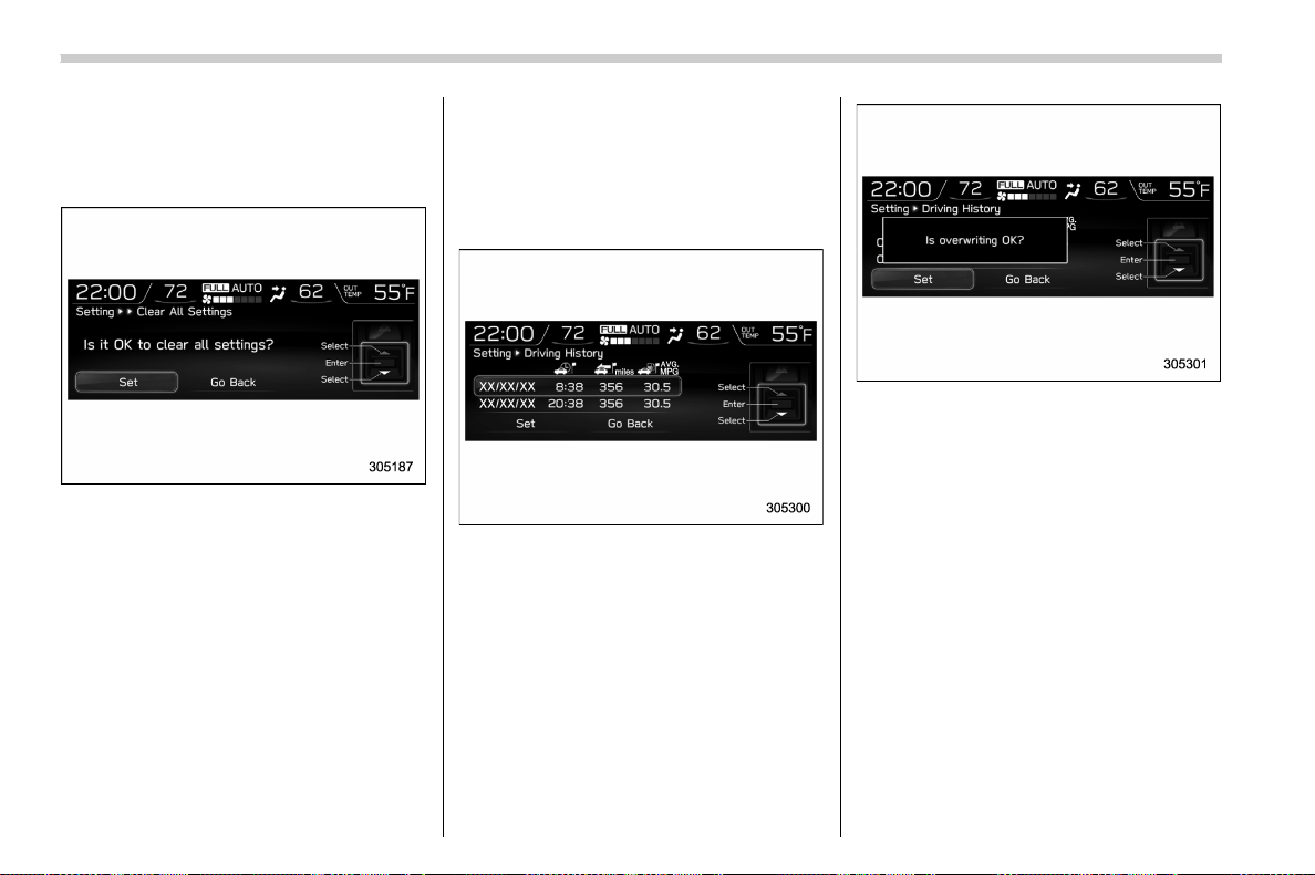
(202,1)
北米Model "A1700BE-B" EDITED: 2017/ 10/ 11
! Clear setting
1. Select “Clear All Settings” from the
2nd menu on the setting screen. Refer to
“Setting screen” F3-52.
2. Sele ct “ Set” to clear the settings.
Select “Go Back” to return to the previous
screen without clearing the settings.
! Driving history setting
You can register the items in the driving
history.
1. Select “Driving History” from the top
menu in the setting screen. Refer to
“Setting screen” F3-52.
2. Select one of the registration lines by
using the control switches.
3. Select “Set” to overwrite the previous
registration. Select “Go Back” to return to
the previous screen without overwriting
the previous registration.
Instruments and controls/Multi-function display (color LCD)
3-60
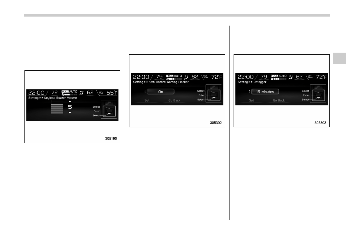
(203,1)
北米Model "A1700BE-B" EDITED: 2017/ 10/ 11
! Car setting
You can set the vehicle setting.
! Keyless buzzer volume setting
1. Select “Keyless Buzzer Volume” from
the 2nd menu in the setting screen. Refer
to “Setting screen” F3-52.
2. Select a volume level by using the
control switches.
3. Press the ENTER button to confirm the
setting.
! Hazard warning flasher setting
1. Select “ Hazard Warning Flasher”
from the 2nd menu in the setting screen.
Refer to “Setting screen” F3-52.
2. Selec t “On” or “Off” by using the
control switches.
3. Select “Set” to exit settings. Select “Go
Back” to return to the previous screen
without applying the setting changes.
! Defogger setting
1. Select “Defogger” from the 2nd menu
in the setting screen. Refer to “Setting
screen” F3-52.
2. Select the preferred setting by using
the control switches.
3. Select “Set” to exit settings. Select “Go
Back” to return to the previous screen
without applying the setting changes.
! Interior light setting
The setting procedure is the same as
“Defogger setting” F3-61, but select the
“Interior Light” item in step 1.
! Auto light sensor setting
The setting procedure is the same as
“Defogger setting” F3-61, but select the
– CONTINUED –
Instruments and controls/Multi-function display (color LCD)
3-61
3
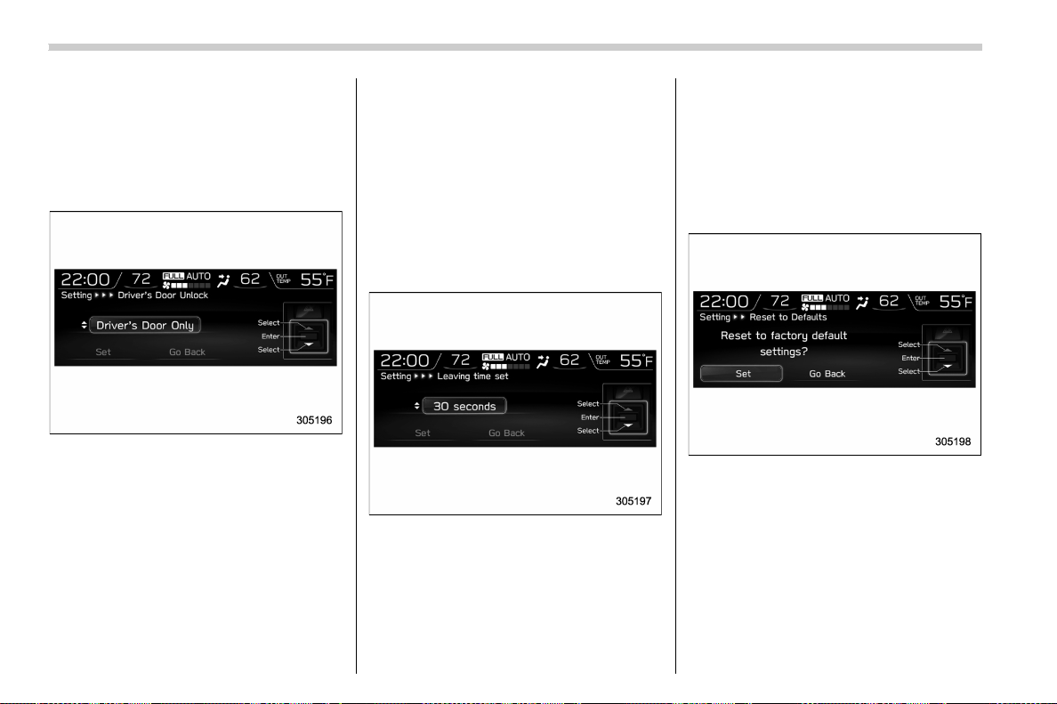
(204,1)
北米Model "A1700BE-B" EDITED: 2017/ 10/ 11
“Auto Light Sensor” item in step 1.
! Keyless Access setting
1. Select “Keyless Access Setting” from
the 2nd menu in the setting screen. Refer
to “Setting screen” F3-52.
2. Select “Driver’s Door Unlock”.
3. Select the preferred setting by using
the control switches.
4. Select “Set” to exit settings. Select “Go
Back” to return to the previous screen
without applying the setting changes.
! Welcome lighting setting
You can change the setting for the period
of time in which the exterior remain on by
the welcome lighting function.
1. Select “Welcome Lighting” from the
2nd menu in the setting screen. Refer to
“Setting screen” F3-52.
2. Select “Leaving time set” to change
the setting when leaving the vehicle.
Select “Approaching time set” to change
the setting when approaching.
3. Select the preferred setting by using
the control switches.
4. Select “Set” to exit settings. Select “Go
Back” to return to the previous screen
without applying the setting changes.
! Initialize
You can initialize the items that have been
set to your preference.
! Reset to factory default settings
1. Select “Reset to Defaults” from the
2nd menu in the setting screen. Refer to
“Setting screen” F3-52.
2. Select “Set” to exit settings. Select “Go
Back” to return to the previous screen
without resetting.
! Lifetime fuel consumption reset-
ting
1. Select “Lifetime Fuel Cons Reset”
from the 2nd menu in the setting screen.
Refer to “Setting screen” F3-52.
Instruments and controls/Multi-function display (color LCD)
3-62
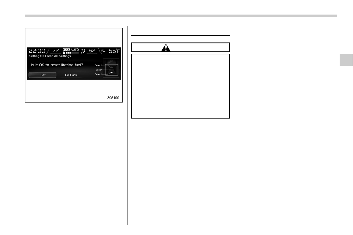
(205,1)
北米Model "A1700BE-B" EDITED: 2017/ 10/ 11
2. Select “Set” to exit settings. Select “Go
Back” to return to the previous screen
without resetting.
& How to get the source code
using the open source
Free/Open Source Software Information
This product contains Free/Open Source
Software (FOSS).
The license information and/or the source
code of such FOSS can be found at the
following URL.
http://www.globald enso.com/en/open-
source/ivi/subaru/
Light control switch
CAUTION
. Use of any lights for a long period
of time while the engine is not
running can cause the battery to
discharge.
. Before leaving the vehicle, make
sure that the lights are turned off.
If the vehicle is left unattended
for a long time with the lights
illuminated, the battery may be
discharged.
Models with “keyless access with
push-button start system”:
The light control switch operates when the
push-button ignition switch is in the “ACC”
or “ON” position.
Regardless of the position of the light
control switch, the illuminated lights are
turned off when the push-button ignition
switch is turned off.
Models without “keyless access with
push-button start system”:
The light control switch operates when the
key is inserted in the ignition switch.
Regardless of the position of the light
control switch, the illuminated lights are
turned off when the key is removed from
the ignition switch.
NOTE
The light control switch can be oper-
ated (except auto on/off headlights),
even under the following conditions.
. when the p ush-button ignition
switch is turned off (models with “key-
less access with push-button start
system”)
. when the key is not inserted into the
ignition switch (models without “key-
less access with push-button start
system”)
When opening the driver’s door with
the headlights illuminated under such
conditions, the chirp sound will inform
the driver that the lights are illuminated.
– CONTINUED –
Instruments and controls/Light control switch
3-63
3
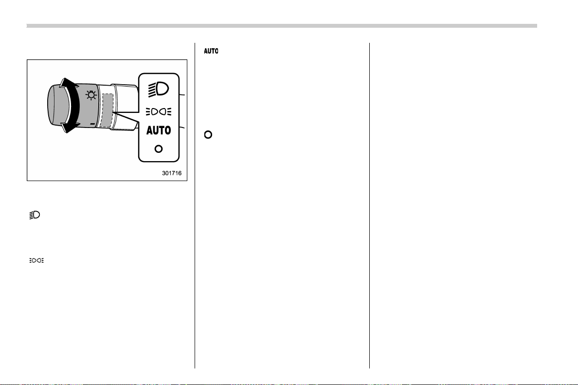
(206,1)
北米Model "A1700BE-B" EDITED: 2017/ 10/ 11
& Headlights
To turn on the headlights, turn the knob on
the end of the turn signal lever.
“
” position
Headlights, parking lights, front side mar-
ker lights, rear side marker lights, tail lights
and license plate lights are on.
“
” position
Parking lights, front side marker lights, rear
side marker lights, tail lights and license
plate lights are on.
“
” position: auto on/off headlights (if
equipped)
When the ignition switch is in the “ON”
position, headlights, parking lights, front
side marker lights, rear side marker lights,
tail lights and license plate lights are
automatically on or off depending on the
level of the ambient light.
“
” position
The headlights are all off.
NOTE
The sensitivity of the auto on/off head-
lights can be changed by a SUBARU
dealer. Consult your SUBARU dealer
for details. Also, you can change the
settings using the multi-function dis-
play (color LCD). For details, refer to
“Auto light sensor setting” F3-61.
! Auto-on/off wiper-linked headlights
(models with auto on/off headlights)
While the light control switch is in the
“AUTO” position, the headlights will auto-
matically turn on when the windshield
wipers operate several times. The head-
lights will automatically turn off when the
wipers stop.
The ON/OFF setting of this function can be
changed by a SUBARU dealer. Consult
your SUBARU dealer for details.
! Welcome lighting function (if
equipped)
The welcome lighting function turns on
some exterior lights for smooth approach-
ing to or exiting from the vehicle at night or
in dark places.
The function is activated while all of the
following conditions are met.
. The light control switch is in the “AUTO”
position
. It is dark enough to turn on the auto on/
off headlights
When approaching:
While the welcome lighting function is
activated, some exterior lights will auto-
matically illuminate when unlocking the
doors by using the remote keyless entry
system.
The exterior lights will remain illuminated
for 30 seconds
*1
and then turn off. How-
ever, if any of the following operations are
performed, the exterior lights will turn off.
. Locking the doors using the keyless
access function (if equipped) or the remote
keyless entry system
. Turning the light control switch to a
position other than “AUTO”.
. Turning the ignition switch to the “ON”
position.
Instruments and controls/Light control switch
3-64
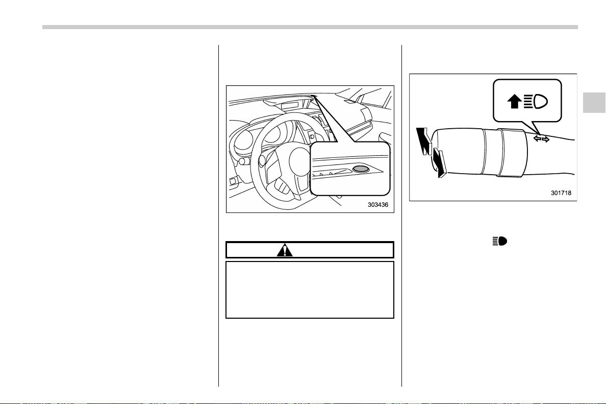
(207,1)
北米Model "A1700BE-B" EDITED: 2017/ 10/ 11
When exiting:
While the welcome lighting function is
activated, some exterior lights will remain
illuminated even when either of the follow-
ing operations is performed.
. Turning the push-button ignition switch
to the “OFF” status (models with “keyless
access with push-button start system”)
. Pulling out the key from the ignition
switch (models without “keyless access
with push-button start system”)
The exterior lights will turn off under any of
the following conditions.
. 3 minutes have passed since the
exterior lights w ere illuminated by the
welcome lighting function.
. 30 seconds have passed since the door
was opened and closed.
*1
. The light control switch is turned to a
position other than “AUTO”.
. The locking procedures using the key-
less access function (if equipped) or the
remote keyless entry system is performed
twice. When performing the unlocking
proce dure after performing the locking
procedure, perform the locking procedure
twice again.
*1: The setting for the period of time in which the
exterior lights remain on by the welcome lighting
function can be changed by a SUBARU dealer.
Contact your SUBARU dealer for details.
! Sensor for the auto on/off head-
lights (if equipped)
The sensor is on the instrument panel as
shown in the illustration.
CAUTION
If any object is placed on or near the
sensor, the sensor may not detect
the level of the ambient light cor-
rectly and the auto on/off headlights
may not operate properly.
& High/low beam change
(dimmer)
To change from low beam to high beam,
push the turn signal lever forward. When
the headlights are on high beam, the high
beam indicator light “
” on the combina-
tion meter is also on.
To switch back to low beam, pull the lever
back to the center position.
! High beam assist function (models
with the EyeSight system)
NOTE
. The high beam assist function uti-
lizes the stereo camera installed at the
position of the front map lights.
. For details on how to handle the
stereo camera, refer to the Owner’s
Manual supplement for the EyeSight
– CONTINUED –
Instruments and controls/Light control switch
3-65
3
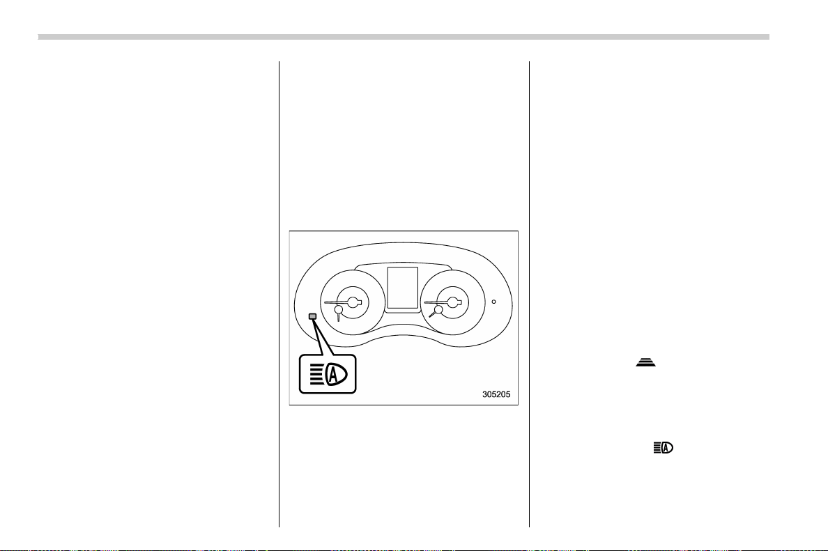
(208,1)
北米Model "A1700BE-B" EDITED: 2017/ 10/ 11
system.
The high beam assist function automati-
cally changes the headlight from high
beam to low beam (or vice versa).
When all of the following conditions are
met, the headlight will change to high
beam.
. The vehicle speed increases to or
above 20 mph (32 km/h).
. There is no preceding or oncoming
vehicle.
. The forward area of the vehicle is dark.
. The road does not have a sharp curve.
When any of the following conditions is
met, the headlight will change to low beam.
. The vehicle speed decreases to or
below 10 mph (16 km/h).
. The forward area o f the vehicle is
bright.
. There is a preceding or oncoming
vehicle.
. The EyeSight system is malfunctioning
or is temporarily stopped.
NOTE
The factory setting (default setting) for
this function is set as “operational”.
This setting can be changed to OFF
(non-operation) at SUBARU dealers.
For more details, contact a SUBARU
dealer.
! How to use the high beam assist
function
The high beam assist function will be
activated when all the following conditions
are met.
. The light control switch is in the “AUTO”
position and the low beam headlights are
on automatically.
. The turn signal lever is pushed forward.
High beam assist indicator (green)
When the high beam assist function is
activated, the high beam assist indicator
on the combination meter will illuminate.
NOTE
If the h igh beam assist function is
malfunctioning or is temporarily
stopped, the headlight will be fixed at
low beam. For details, refer to the
Owner’s Manual supplement for the
EyeSight system.
! How to temporarily lower the
sensitivity of the high beam
assist function
You can lower the sensitivity of the high
beam assist function by performing the
following operations.
1. Before turning the ignition switch to the
“ON” position, set the light control switch to
the “AUTO” position and push the signal
lever forward (high beam position).
2. Turn the ignition switch to the “ON”
position and within approximately 15 sec-
onds, press the “
” (following distance
setting) switch more than 10 times con-
secutively.
When the sensitivity of the high beam
assist function is lowered, the high beam
assist indicator light “
” on the combina-
tion meter will flash.
Instruments and controls/Light control switch
3-66
(209,1)
北米Model "A1700BE-B" EDITED: 2017/ 10/ 11
NOTE
. You cannot lower the sensitivity of
the high beam assist function in the
following conditions.
– Cruise control or Adaptive Cruise
Control is in operation
– The EyeSight warning indicator
(yellow) is illuminated
. The sensitivity of the high beam
assist function returns to normal level
the next ti me the ignition switch is
turned to the “LOCK”/“OFF” position
and the engine is restarted.
! How to change the headlight
mode manually
Change to the low beam:
Return the turn signal lever to the center
position to turn off the high beam assist
function. Then the high beam assist
indicator will turn off.
Change to the high beam:
Turn the light control switch to the “
”
position to change the headlight mode to
the high beam.
At this time, the high beam assist function
will turn off, the high beam assist indicator
will turn off and the high beam indicator
light will turn on.
NOTE
After manually selecting the high beam
mode:
. If you want to turn on the high beam
assist function, return the light control
switch to the “AUTO” position.
. Turn the light control switch to the
“
” position to turn on the instrument
panel illumination, parking lights, front
side marker lights, rear side marker
lights, tail lights and license plate
lights.
! Tips for the high beam assist
function
. The high beam assist function recog-
nizes the condition surrounding the vehicle
based on the brightness of illumination
ahead of your vehicle, etc. Therefore, the
headlight mode may swi tch in s ome
situations that do not match to the driver’s
sense.
. A bicycle or cargo cycle may not be
detected.
. Under the following situations, the high
beam assist function may not work prop-
erly. As a result, the glare of the high beam
may disturb the oncoming vehicle or
vehicle ahead. Also, the low beam mode
may continue although there are no
oncoming vehicles and vehicles ahead.
In the such cases, change the headlight
mode manually.
– In bad weather (fog, snow, sand
storm, heavy rain, etc.)
– When the windshield glass is dirty,
fogged, cracked or damaged
– Whenthestereocameraisde-
formed or the stereo camera lenses
are dirty
– If there are lights similar to the
headlights or the tail lights in the
surrounding area
– When an oncoming vehicle or ve-
hicle ahead is driven without its head-
lights and tail lights on
– If the headlights of an oncoming
vehicle or the tail lights of a vehicle
ahead are dirty or discolored, or if the
light beams are not aimed correctly
– When a rapid change of brightness
continues while driving
– When driving on a road with many
ups and downs, uneven surfaces or
curves
– When there are some objects that
reflect light strongly, such as a road
sign or a mirror in vehicle ahead
– When the rear part of the vehicle
ahead, such as a container, reflects
light strongly
– When the headlights of your vehicle
are damaged or dirty
– CONTINUED –
Instruments and controls/Light control switch
3-67
3
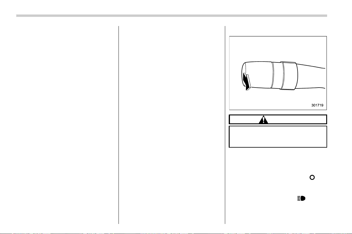
(210,1)
北米Model "A1700BE-B" EDITED: 2017/ 10/ 11
– When your vehicle is tilted, such as
in case the vehicle has a flat tire or is
being towed
– Immediately after the engine has
started
. In the following conditions, the head-
light mode will not be automatically chan-
ged from the high beam to the low beam.
– When your vehicle passes an on-
coming vehicle suddenly in a blind
curve
– When another vehicle passes in
front of your vehicle
– When an oncoming vehicle or ve-
hicle ahead comes in and out of view
because of continuous curves, median
strips, roadside trees, etc.
. If the stereo camera detects the light of
the front fog lights of an oncoming vehicle,
the headlight mode may change from the
high beam to the low beam automatically.
. The headlight mode may change from
the high beam to the low beam, or the low
beam mode may continue, when affected
by a street light, traffic signal, illumination
of an advertisement board, or a reflective
object such as a road sign and signboard.
. The timing of the change of headlight
mode may differ due to the following
factors.
– the vehicle condition (e.g., the num-
ber of passengers or the weight of
loaded cargo)
– surrounding situatio n (e.g., the
movement and direction of an oncom-
ing vehicle or vehicle ahead)
– detection limitations of the camera
angle
& Headlight flasher
CAUTION
Do not hold the lever in the flashing
position for more than just a few
seconds.
To flash the headlights, pull the lever
toward you and then release it. The high
beam will stay on for as long as you hold
the lever. The headlight flasher works even
though the lighting switch is in the “
” (off)
position.
When the headlights are on high beam, the
high beam indicator light “
” on the
combination meter is also on.
Instruments and controls/Light control switch
3-68
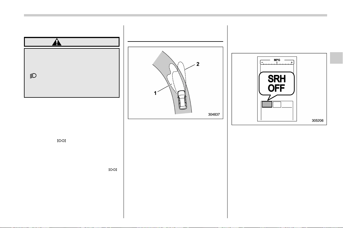
(211,1)
北米Model "A1700BE-B" EDITED: 2017/ 10/ 11
& Daytime running light system
WARNING
When the daytime running lights are
illuminated, the tail lights do not
illuminate. When it becomes dark
outside, turn the light switch to the
“
” position to illuminate the head-
lights and tail lights. This will im-
prove visibility and allow other dri-
vers to see your vehicle more easily.
The daytime running lights will automati-
cally illuminate when the following condi-
tions are fulfilled.
. The engine is running.
. The parking brake is fully released.
. The light control switch is in the “AUTO”
(if equipped), “
” or off position.
. For CVT models, the select lever is in a
position other than the “P” position.
NOTE
When the light switch is in the “ ”
position, the instrument panel illumina-
tion, front side marker lights, tail lights
and license plate lights are also illumi-
nated.
Steering Responsive Head-
light (SRH) (if equipped)
1) The target area of illumination when SRH
is activated
2) The target area of illumination when SRH
is not activated
SRH is a function that automatically moves
the headlight beam to the left or right in
accordance with the steering angle and
vehicle speed. This function helps to
improve the visibility at night by illuminat-
ing the road ahead at corners and inter-
sections.
NOTE
SRH only activates when the vehicle is
traveling forward at the speed of ap-
proximately 5 mph (8 km/h) and over.
& To turn on/off the SRH
Operate the combination meter display
(color LCD) to turn on/off the SRH. For
details, refer to “ SRH” F3-43.
SRH OFF indicator
The SRH OFF indicator on the combina-
tion meter turns off when SRH is turned on.
The SRH OFF indicator on the combina-
tion meter illuminates when SRH is turned
off.
If SRH is malfunctioning, a message
appears on the warning screen when the
ignition switch is in the “ON” position. It
indicates that SRH has been deactivated.
Contact a SUBARU dealer for an inspec-
tion.
– CONTINUED –
Instruments and controls/Steering Responsive Headlight (SRH)
3-69
3
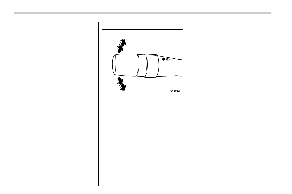
(212,1)
北米Model "A1700BE-B" EDITED: 2017/ 10/ 11
NOTE
When you turn the ignition switch to the
“ON” position, the SRH OFF indicator
will illuminate and turn off after several
seconds.
Turn signal lever
To activate the right turn signal, push the
turn signal lever up. To activate the left turn
signal, push the turn signal lever down.
When the turn is finished, the lever will
return automatically. If the lever does not
return after cornering, return the lever to
the neutral position by hand.
To signal a lane change, push the turn
signal lever up or down slightly and hold it
during the lane change. The turn signal
indicator lights will flash in the direction of
the turn or lane change. The lever will
return automatically to the neutral position
when you release it.
& One-touch lane changer
To flash the turn signal and turn signal
indicator light three times, push the turn
signal lever up or down slightly and
immediately release it.
The operational/non-operational setting of
the one-touch lane changer’scanbe
changed by a SUBARU dealer. Contact
the nearest SUBARU dealer for details.
Instruments and controls/Turn signal lever
3-70
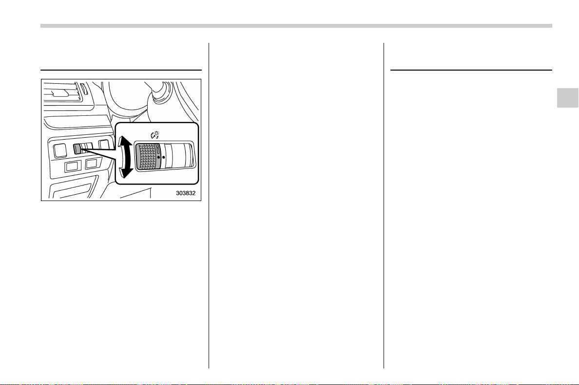
(213,1)
北米Model "A1700BE-B" EDITED: 2017/ 10/ 11
Illumination brightness con-
trol
You can adjust the illumination brightness
of the combination meter, the climate
control panel, etc. by turning the control
dial.
. To brighten, turn the control dial up-
ward.
. To darken, turn the control dial down-
ward.
Themulti-functiondisplay(colorLCD)
automatically adjusts its brightness to-
gether with the brightness level of the
instrument panel. To adjust the display’s
contrast, refer to “Contrast setting” F3-56.
NOTE
The brightness setting is not canceled
even when the ignition switch is turned
to the “LOCK”/“OFF” position.
& Automatic dimming function
If you turn on the parking lights, the
illumination brightness of the combination
meter, the climate control panel or other
functions will automatically darken.
NOTE
When you turn the control dial fully
upward, the illumination brightness
becomes the maximum level and the
automatic dimming function will not
work at all.
& Auto dimmer cancel function
If you turn on the parking lights with the
ambient light bright, the illumination bright-
ness of such items will not darken.
The operational/non -oper at io nal setting
and sensitivity of the auto dimmer cancel
function can be changed by your SUBARU
dealer. Contact your SUBARU dealer for
details.
Headlight beam leveler (if
equipped)
& Automatic headlight beam
leveler (models with LED
headlights)
The LED headlights generate more light
than conventional halogen headlights.
Therefore a driver of an oncoming vehicle
may experience too much glare if your
headlight beam height adjustment is high
when the vehicle is carrying a heavy load.
The automatic headlight beam leveler
adjusts the headlight beam height auto-
matically and optimally according to the
load being carried by the vehicle.
Instruments and controls/Illumination brightness control
3-71
3
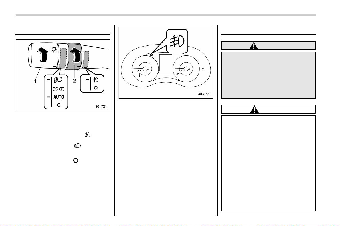
(214,1)
北米Model "A1700BE-B" EDITED: 2017/ 10/ 11
Fog light switch (if equipped)
1) Headlight switch
2) Fog light switch
The front fog lights will turn on when the
fog light switch is placed in the “
” position
while the headlig hts are on (e.g., the
headlight switch is in the “
” position.)
To turn off the front fog lights, turn the
switch back down to the “
” position.
Front fog light indicator light
The indicator light on the combination
meter will illuminate when the front fog
lights are illuminated.
Wiper and washer
WARNING
In freezing weather, do not use the
windshield washer until the wind-
shield is sufficiently warmed by the
defroster.
Otherwise the washer fluid can
freeze on the windshield, blocking
your view.
CAUTION
. Do not operate the washer con-
tinuously for more than 10 sec-
onds, or when the washer fluid
tank is empty. This may cause
overheating of the washer motor.
Check the washer fluid level fre-
quently, such as at fuel stops.
. Do not operate the wipers when
the windshield is dry. This may
scratch the glass, damage the
blade rubbers and might cause
the wiper motor to fail. Before
operating the wiper on a dry
windshield, always use the wind-
shield washer.
. In freezing weather, be sure that
Instruments and controls/Fog light switch
3-72
(215,1)
北米Model "A1700BE-B" EDITED: 2017/ 10/ 11
the blade rubbers are not frozen
to the windshield before switch-
ing on the wipers. Attempting to
operate the wiper with the blade
rubbers frozen to the window
glass could cause not only the
blade rubbers to be damaged but
also might cause the wiper motor
to fail. If the blade rubbers are
frozen to the window glass, be
sure to operate the defroster or
the windshield wiper deicer (if
equipped) before turning on the
wiper.
. If the wipers stop during opera-
tion because of ice or some other
obstruction on the window, this
might cause the wiper motor to
fail even if the wiper switch is
turned off. If this occurs,
promptly stop the vehicle in a
safe place, turn the ignition
switch to the “LOCK”/“OFF” po-
sition and clean the window glass
to allow proper wiper operation.
. Use clean water if windshield
washer fluid is una vailable. In
areas where water freezes in
winter, use SUBARU Windshield
Washer Fluid or the equivalent.
Refer to “Windshield washer
fluid” F11-38.
Also, when driving the vehicle
when there are freezing tempera-
tures, use non-freezing type wi-
per blades.
. Do not clean the wiper blades
with gasoline or a solvent, such
as paint thinner or benzine. This
will cause deterioration of the
wiper blades.
NOTE
. The windshield wiper motor is pro-
tected against overloads by a circuit
breaker. If the motor operates continu-
ously under an unusually heavy load,
the circuit breaker may trip to stop the
motor temporarily. If this happens, park
your vehicle in a safe place, turn off the
wiper switch, and wait for approxi-
mately 10 minutes. The circuit breaker
will reset itself, and the wipers will
again operate normally.
. Clean your blade rubbers and win-
dow glass periodically with a washer
solution to prevent streaking, and to
remove accumulations of road salt or
road film. Operate the windshield
washer for at least 1 second so that
washer solution will be sprinkled all
over the windshield.
. Grease, wax, insects or other mate-
rial on the windshield or the blade
rubbers results in jerky wiper operation
and streaking on the glass. If you
cannot remove those streaks after
operating the washer or if the wiper
operation is jerky, clean the outer sur-
face of the windshield and the blade
rubbers using a sponge or soft cloth
with a neutral detergent or mild-abra-
sive cleaner. After cleaning, rinse the
window glass and blade rubbers with
clean water. The glass is clean if no
beads form on the glass when you rinse
with water.
. If you cannot eliminate the streaking
even after following this procedure,
replace the wiper blades (or blade
rubbers) with new ones. For replace-
ment instructions, refer to “Replace-
ment of wiper blades” F11-39.
– CONTINUED –
Instruments and controls/Wiper and washer
3-73
3
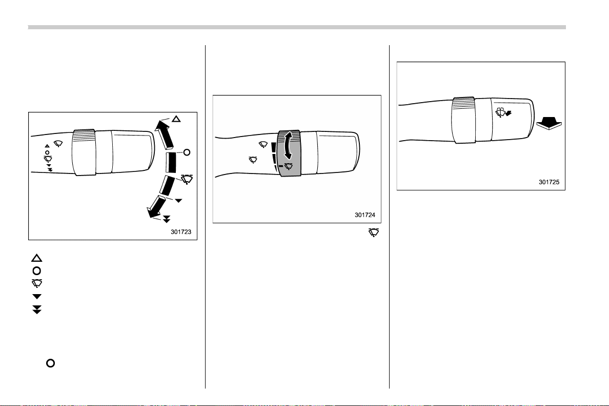
(216,1)
北米Model "A1700BE-B" EDITED: 2017/ 10/ 11
& Windshield wiper and washer
switches
The wiper operates only when the ignition
switch is in the “ON” position.
! Windshield wipers
: Mist (for a single wipe)
:Off
: Intermittent
: Low speed
:
High speed
To turn the wipers on, push the wiper
control lever down.
To turn the wipers off, return the lever to
the “
” position.
For a single wipe of the wipers, push the
lever up. The wipers operate until you
release the lever.
! Wiper intermittent time control
When the wiper switch is in the “ ”
position, turn the dial to adjust the operat-
ing interval of the wiper. You can adjust the
operating interval in several steps.
! Windshield washer
To wash the windshield, pull the wiper
control lever toward you. The washer fluid
sprays until you release the lever. The
wipers operate while you pull the lever.
Instruments and controls/Wiper and washer
3-74
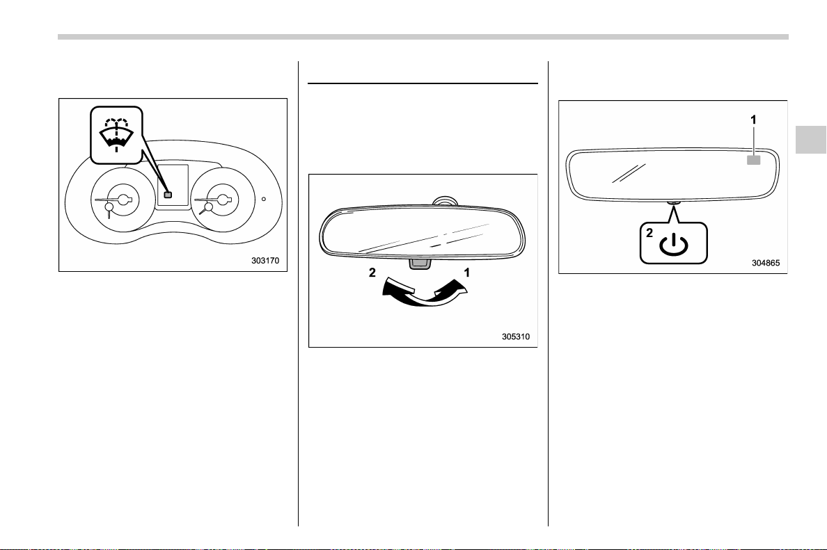
(217,1)
北米Model "A1700BE-B" EDITED: 2017/ 10/ 11
NOTE
The windshield washer fluid warning
indicator appears when the washer
fluid level in the tank has dropped to
the lower limit. If the warning indicator
appears, refill the tank with fluid. For
the refilling procedure, refer to “Wind-
shield washer fluid” F11-38.
Mirrors
Always check that the inside and outside
mirrors are properly adjusted before you
start driving.
& Inside mirror
1) Normal position
2) Anti-glare position
Push the tab on the mirror for normal use.
To reduce glare from the headlights of the
vehicle behind you, pull the tab to the anti-
glare position.
& Auto-dimming mirror/com-
pass (if equipped)
1) Display
2) Switch
During nighttime driving, the auto-dimming
feature senses distracting glare from
vehicle headlights behind you and auto-
matically dims to eliminate the glare and
preserve your vision.
– CONTINUED –
Instruments and controls/Mirrors
3-75
3
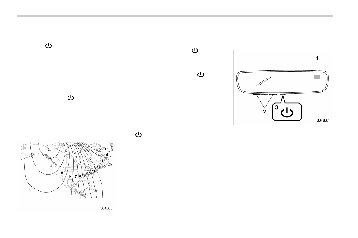
(218,1)
北米Model "A1700BE-B" EDITED: 2017/ 10/ 11
! To Operate the Auto-Dimming Fea-
ture
Press the “
” switch to turn the auto-
dimming feature on/off. The auto-dimming
feature is enabled when the switch’s green
LED indicator is on. The auto-dimming
feature will default to on with each ignition
cycle.
! To Operate the Compass Feature
1. To turn the compass feature on/off,
press and hold the “
” switch for more
than 3 seconds or until the display turns
on/off. The compass feature will default to
on with each ignition cycle.
2. If the display reads “C”, slowly drive the
vehicle in circles until compass is cali-
brated.
Compass calibration zones
3. To adjust for compass zone variance:
(1) Find your current location and
zone number on the map.
(2) Press and hold the “
” switch for
more than 6 seconds or until a zone
number appears in the display.
(3) Once the zone number appears in
the display, toggle the “
” switch
again until your current location zone
number appears. After you stop press-
ing the switch, your new zone number
will be saved. Within a few seconds,
the display will show a compass direc-
tion.
4. If the vehicle’s magnetics have chan-
ged or if the compass appears inaccurate,
recalibrate the compass. Press and hold
the “
” switch for more than 9 seconds or
until a “C” appears in the display. Once a
“C” appears in the display, slowly drive the
vehicle in circles until compass is cali-
brated.
& Auto-dimming mirror/com-
pass with HomeLink
®
(if
equipped)
1) Display
2) HomeLink Buttons
3) Switch
During nighttime driving, the auto-dimming
feature senses distracting glare from
vehicle headlights behind you and auto-
matically dims to eliminate the glare and
preserve your vision.
Instruments and controls/Mirrors
3-76
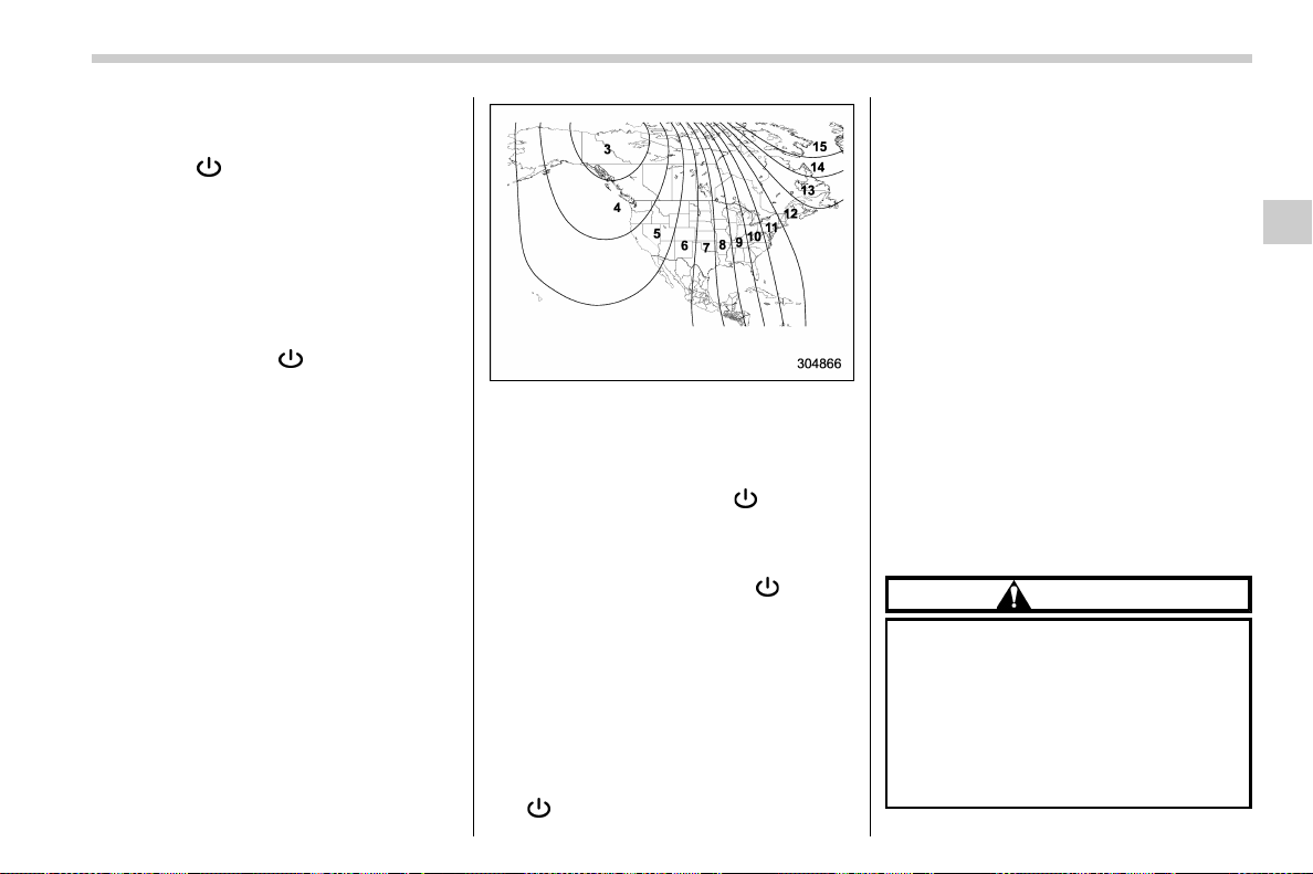
(219,1)
北米Model "A1700BE-B" EDITED: 2017/ 10/ 11
! To Operate the Auto-Dimming Fea-
ture
Press the “
” switch to turn the auto-
dimming feature on/off. The auto-dimming
feature is enabled when the switch’s green
LED indicator is on. The auto-dimming
feature will default to on with each ignition
cycle.
! To Operate the Compass Feature
1. To turn the compass feature on/off,
press and hold the “
” switch for more
than 3 seconds or until the display turns
on/off. The compass feature will default to
on with each ignition cycle.
2. If the display reads “C”, slowly drive the
vehicle in circles until compass is cali-
brated.
Compass calibration zones
3. To adjust for compass zone variance:
(1) Find your current location and
zone number on the map.
(2) Press and hold the “
” switch for
more than 6 seconds or until a zone
number appears in the display.
(3) Once the zone number appears in
the display, toggle the “
” switch
again until your current location zone
number appears. After you stop press-
ing the switch, your new zone number
will be saved. Within a few seconds,
the display will show a compass direc-
tion.
4. If the vehicle’s magnetics have chan-
ged or if the compass appears inaccurate,
recalibrate the compass. Press and hold
the “
” switch for more than 9 seconds or
until a “C” appears in the display. Once a
“C” appears in the display, slowly drive the
vehicle in circles until compass is cali-
brated.
! HomeLink
®
Wireless Control Sys-
tem
The HomeLink
®
Wireless Control System
provides a convenient way to replace up to
three hand-held radio-frequency remotes
used to activate devices such as gate
operators, garage door openers, entry
door locks, security systems, even home
lighting. The bel ow steps are generic
programming instructions; for Genie and
Sommer garage door openers please go
directly to the HomeLink website. Addi-
tional information and programming vi-
deos can be found at
www.HomeLink.com and
www.youtube.com/HomeLinkGentex.
CAUTION
. Before programming HomeLink
to a garage door opener or gate
operator, make sure that people
and objects are out of the way of
the device to prevent potential
harm or damage.
. When programming a garage
door opener, it is advised to park
– CONTINUED –
Instruments and controls/Mirrors
3-77
3
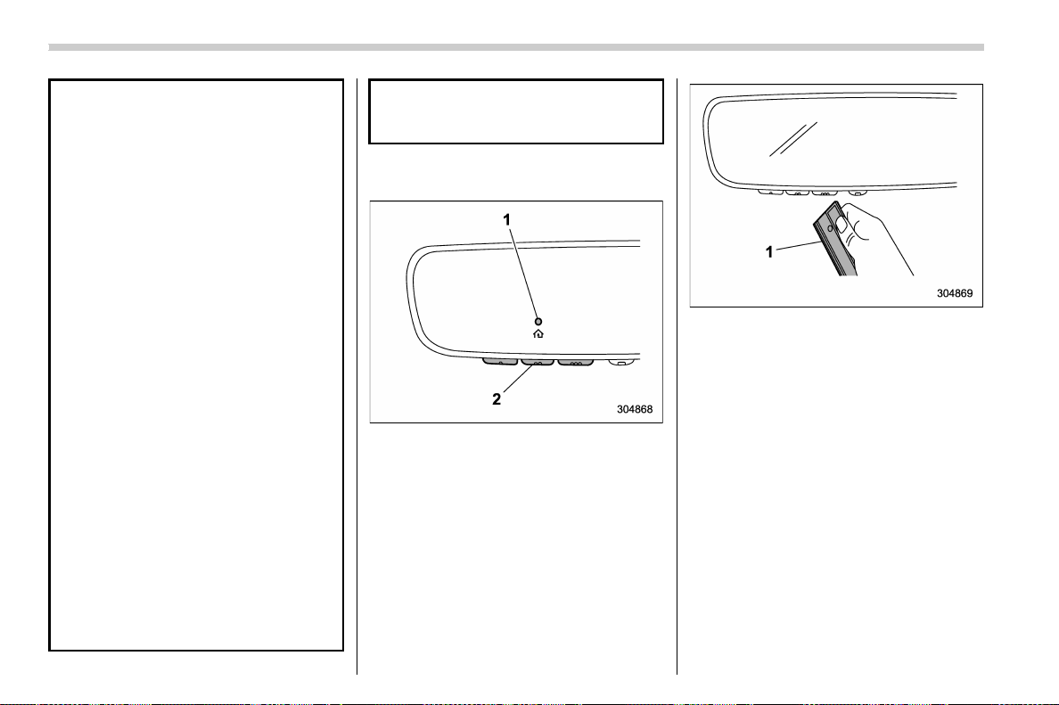
(220,1)
北米Model "A1700BE-B" EDITED: 2017/ 10/ 11
outside of the garage.
. Do not use HomeLink with any
garage door opener that lacks
safety stop and reverse features
as required by U.S. federal safety
standards (this includes any gar-
age door opener model manufac-
tured before April 1, 1982). A
garage door that cannot detect
an object signaling the door to
stop and reverse does not meet
current U.S. federal safety stan-
dards.
. It is also recommended that a new
battery be placed in the hand-
held remote (garage door opener
remote) of the device for quicker
and more accurate training.
. Some vehicles may require the
ignition switch to be turned to the
“ON” or “ACC” position for pro-
gramming and/or operation of
HomeLink.
. Keep the hand-held remote (gar-
age door opener remote) of the
device you are programming for
use in other vehicles as well as
for future HomeLink program-
ming. It is also suggested that
upon the sale of the vehicle, the
programmed HomeLink buttons
be erased for security purposes.
Refer to “Erasing HomeLink But-
tons” F3-81.
! Programming a New HomeLink
Button
1) Indicator Light
2) HomeLink Buttons
1. Press and release the HomeLink but-
ton that you would like to program. The
HomeLink indicator light will flash orange
slowly (if not, refer to “Erasing HomeLink
Buttons” F3-81).
1) Garage door opener remote
2. Position the hand-held remote (garage
door opener remote) 1 to 3 inches (2 to 8
cm) away from the HomeLink button that
you would like to program.
NOTE
Some hand-held remotes (garage door
opener remotes) may actually train
better at a distance of 6 to 12 inches
(15 to 30 cm). Keep this in mind if you
have difficulty with the programming
process.
Instruments and controls/Mirrors
3-78
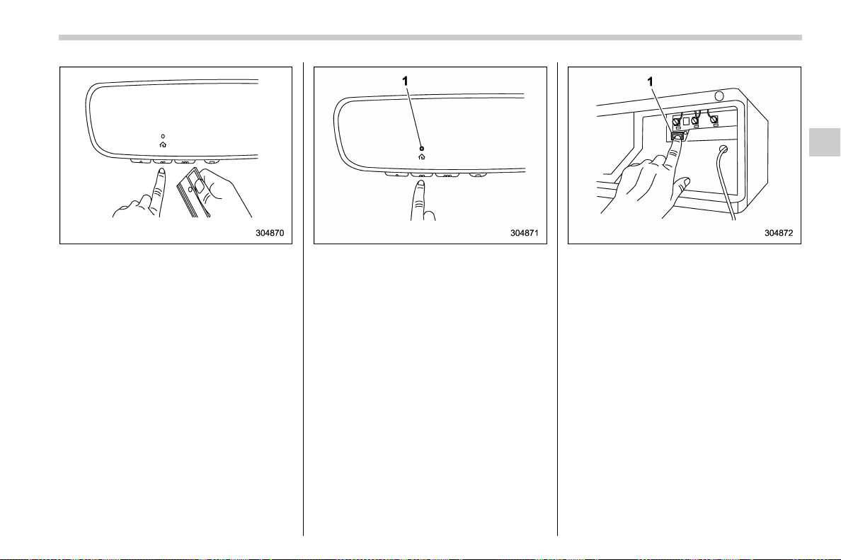
(221,1)
北米Model "A1700BE-B" EDITED: 2017/ 10/ 11
3. While the HomeLink indicator light is
flashing orange, press and hold the hand-
held remote button. Continue pressing the
hand-held remote button until the
HomeLink indicator light changes from
orange to green. You may now release
the hand-held remote button.
NOTE
Some devices may require you to re-
place this “ Programming a New
HomeLink Button” step 3 with proce-
dures noted in the “Gate Operator /
Canadian Programming” section. Refer
to “Gate Operator / Canadian Program-
ming” F3-80.
1) Indicator Light
4. Press the HomeLink button that you
would like to program and observe the
indicator light.
. If the indicator light remains constant
green, your device should operate
when the HomeLink button is pressed.
At this point, if your device operates,
programming is complete.
. If the indicator light rapidly flashes
green, firmly press, hold for two sec-
onds and release the HomeLink button
up to three times to comp lete the
programming process. At this point if
your device operates, programming is
complete. If the device does not
operate, continue with the next step
of the programming instructions.
1) “Learn” button
5. At the garage door opener mo tor,
(security gate motor, etc.) locate the
“Learn”, “Smart”,or“Program” button. This
can usually be found where the hanging
antenna wire is attached to the motor-head
unit (see the device’s manual to identify
this button). The name and color of the
button may vary by manufacturer.
NOTE
A ladder and/or second person may
simplify the following steps.
6. Firmly press and release the “ Learn”,
“Smart”,or“Program” button. You now
have 30 seconds in which to complete step
7.
– CONTINUED –
Instruments and controls/Mirrors
3-79
3
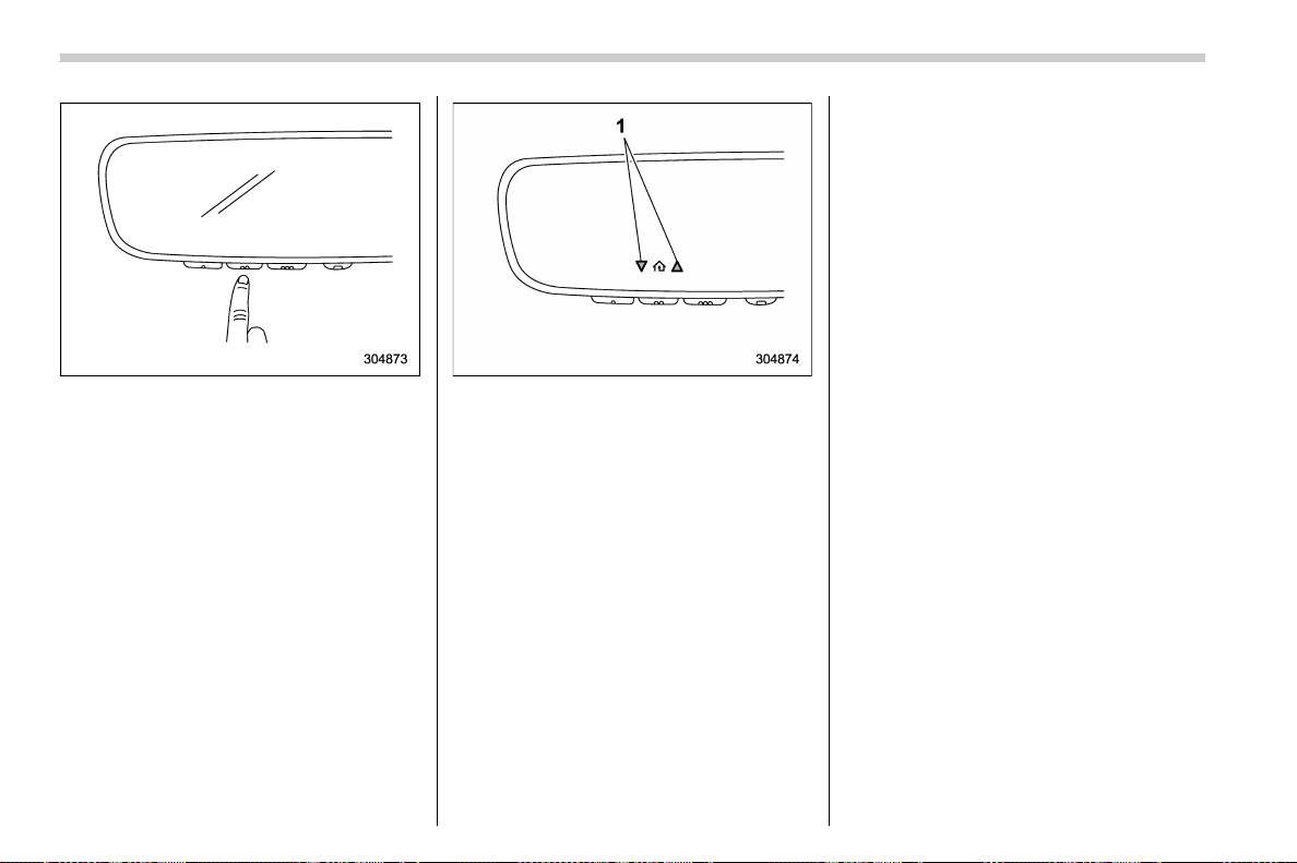
(222,1)
北米Model "A1700BE-B" EDITED: 2017/ 10/ 11
7. Return to the vehicle and firmly press,
hold for two seconds and release the
HomeLink button up to three times. At this
point programming is complete and your
device should operate when the HomeLink
button is pressed and released.
1) Status Indicators
8. If status indicator arrows appear next
to the indicator light, please refe r to
“Garage Door Two-Way Communication”
F3-81.
In the event that there are still program-
ming difficulties or questions, additional
HomeLink information and programming
videos can be found at
www.HomeLink.com and
www.youtube.com/HomeLinkGentex. For
Genie and Sommer garage door openers
please go directly to the HomeLink web-
site.
! Gate Operator / Canadian Pro-
gramming
Canadian radio-frequency laws require
transmitter remote signals to “time-out”
(or quit) after several seconds of transmis-
sion, which may not be long enough for
HomeLink to pick up the signal during
programming. Similar to this Canadian
law, some U.S. gate operators are de-
signed to “time-out ” in the same manner.
The indic ator LED o n the h and-held
remote will go off when the device times
out, indicating that it has finished transmit-
ting.
If you live in Canada or you are having
difficulties programming a gate operator or
garage door opener by using the program-
ming procedures, replace “Programming a
New HomeLink Button” step 3 with the
following:
While the HomeLink indicator light is
flashing orange, press and release (“cy-
cle”) your device’s hand-held remote every
two seconds until the HomeLink indicator
light changes from orange to green. You
may now release the hand-held remote
button.
NOTE
If programming a garage door opener
or gate operator, it is advised to unplug
Instruments and controls/Mirrors
3-80
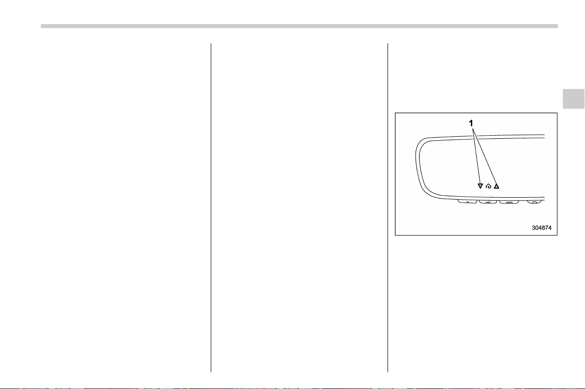
(223,1)
北米Model "A1700BE-B" EDITED: 2017/ 10/ 11
the device during the “cycling” process
to prevent possible overheating.
Proceed with “ Progra mming a New
HomeLink Button” step 4 to complete.
! Using HomeLink
To operate, simply press and release the
programmed HomeLink button. Activation
will now occur for the trained device (i.e.
garage door opener, gate operator, secur-
ity system, entry door lock, home/office
lighting, etc.). For convenience, the hand-
held remote of the device may also be
used at any time.
! Erasing HomeLink Buttons
To erase programming from the three
buttons (individual buttons cannot be
erased but can be “reprogrammed” as
outlined below), follow the step noted:
Press and hold the two outer HomeLink
buttons for at least 10 seconds. The LED
indicator will change from continuously lit
to rapidly flashing. Release both buttons.
Do not hold for longer than 20 seconds.
HomeLink is now ready to be programmed
at any time beginning with “Programming a
New HomeLink Button” - step 1.
! Reprogramming a Single
HomeLink Button
To program a previously trained button,
follow these steps:
1. Press and hold the desired HomeLink
button. DO NOT release the button.
2. The indicator light will begin to slowly
flash orange after 20 seconds. The
HomeLink button can be released at this
point. Proceed with “Programming a New
HomeLink Button” - step 3.
3. If you do not complete the program-
ming of a new device to the button, it will
revert to the previously stored program-
ming.
! Garage Door Two-Way Commu-
nication
HomeLink has the capability of commu-
nicating with your garage door opener.
HomeLink can receive and display “clos-
ing” or “opening” status messages from
compatible garage door opener systems.
At any time, HomeLink can also recall and
display the last recorded status commu-
nicated by the garage door opener to
indicate your garage door being “closed”
or “opened”.
HomeLink has the capability of receiving
this communication from the garage door
opener at a range up to 820 feet (250 m).
Range may be reduced by obstacles such
as houses or trees. You may have to slow
your vehicle speed to successfully receive
the garage door opener communication.
! Programming Two-Way Commu-
nication
1) Status Indicators
Within five seconds after programming a
new HomeLink button, both of HomeLink’s
garage door status indicators will flash
rapidly green indicating that the garage
door two-way communication has been
enabled. If your garage door status in-
dicators flashed, two-way communication
programming is complete.
If the garage door status indicators do not
flash, additional HomeLink information
and programming videos can be found
– CONTINUED –
Instruments and controls/Mirrors
3-81
3
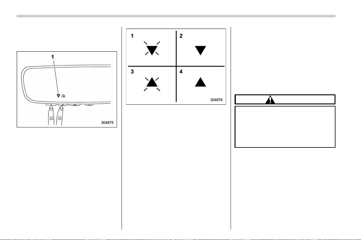
(224,1)
北米Model "A1700BE-B" EDITED: 2017/ 10/ 11
online at www.HomeLink.com and
www.youtube.com/HomeLinkGentex.
! Using Two-Way Communication
1) Status Indicators
Recall and display (at any time) the last
recorded garage door status message
communicated to HomeLink by simulta-
neously pressing HomeLink buttons 1 and
2 for two seconds. HomeLink will display
the last recorded status for three seconds.
1) Garage Door Opener CLOSING (Blinking
Orange)
2) Garage Door Opener CLOSED (Solid
Green)
3) Garage Door Opener OPENING (Blink-
ing Orange)
4) Garage Door Opener OPENED (Solid
Green)
If two-way communication programming is
successful, HomeLink will display the
status of your garage door opener with
arrow indicators.
! Certification
In the event that there are still program-
ming difficulties or questions, additional
HomeLink information and programming
videos can be found at
www.HomeLink.com,
www.y outube .com/ HomeLi nkGen tex, or
by calling the toll-free HomeLink-hotline
at 1-800-355-3515.
. U.S.-spec. models
CAUTION
FCC WARNING
Changes or modifications not ex-
pressly approved by the party re-
sponsible for compliance could void
the user’s authority to operate the
equipment.
This device complies with part 15 of the
FCC Rules. Operation is subject to the
following two conditions: (1) This de-
vice may not cause harmful interfer-
ence, and (2) this device must accept
any interference received, including
interference that may cause undesired
operation.
Instruments and controls/Mirrors
3-82
(225,1)
北米Model "A1700BE-B" EDITED: 2017/ 10/ 11
. Canada-spec. models
HomeLink
®
and the HomeLink
®
house are
registered trademarks of Gentex Corpora-
tion.
WARNING
. When programming the
HomeLink
®
Wireless Control Sys-
tem, you m ay be operating a
garage door opener or other
device. Make sure that people
and objects are out of the way of
the garage door or other device
to prevent potential harm or da-
mage.
. Do not use the HomeLink
®
Wire-
less Control System with a gar-
age door opener that lacks the
safety stop and reverse feature
as required by applicable safety
standards. A garage door opener
which cannot detect an object,
signaling the door to stop and
reverse, does not meet these
safety standards. Using a garage
door opener without these fea-
tures increases risk of serious
injury or death. For more infor-
mation, consult the HomeLink
®
website at www.homelink.com or
call 1-800-355-3515.
& Outside mirrors
! Convex mirror (passenger side)
WARNING
Objects look smaller in a convex
mirror and farther away than when
viewed in a flat mirror. Do not use the
convex mirror to judge the distance
of vehicles behind you when chan-
ging lanes. Use the inside mirror (or
glance backwards) to determine the
actual size and distance of objects
that you view in convex mirror.
– CONTINUED –
Instruments and controls/Mirrors
3-83
3
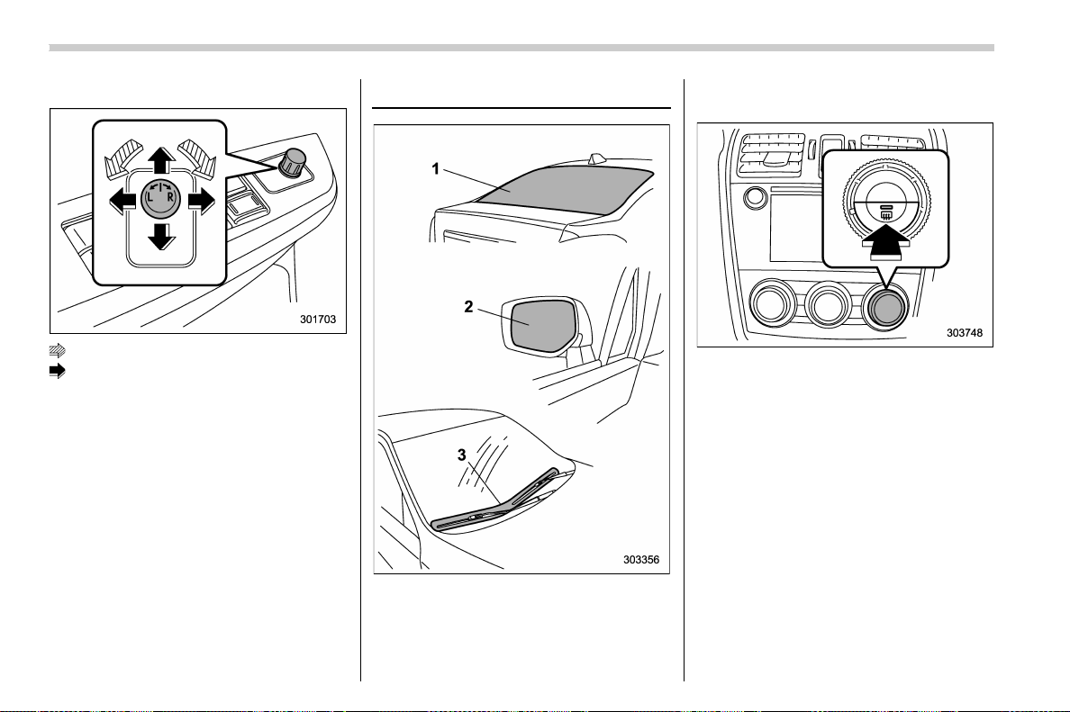
(226,1)
北米Model "A1700BE-B" EDITED: 2017/ 10/ 11
! Remote control mirror switch
: Select side to adjust
: Direction control
The remote control mirrors operate only
when the ignition switch is in the “ON” or
“ACC” position.
1. Turn the control switch to the side that
you want to adjust. “L” is for the left mirror,
“R” is for the right mirror.
2. Move the control switch in the direction
you want to move the mirror.
3. Return the control switch to the neutral
position to prevent unintentional opera-
tion.
You can also adjust the mirrors manually.
Defogger and deicer
1) Rear window defogger
2) Outside mirror defogger
3) Windshield wiper deicer (if equipped)
The defogger and deicer system is acti-
vated only when the ignition switch is in the
“ON” position.
Control switch
To activate the defogger and deicer sys-
tem, press the control switch that is located
on the climate control panel. The rear
window defogger, outside mirror defogger
and windshield wiper deicer are activated
simultaneously. The indicator light on the
control switch illuminates while the defog-
ger and deicer system is activated.
To turn them off, press the control switch
again. They also turn off when the ignition
switch is turned to the “ACC ” or “ LOCK”/
“OFF” position.
The defogger and deicer system will
automatically shut off after approximately
15 minutes. If the rear window and the
Instruments and controls/Defogger and deicer
3-84
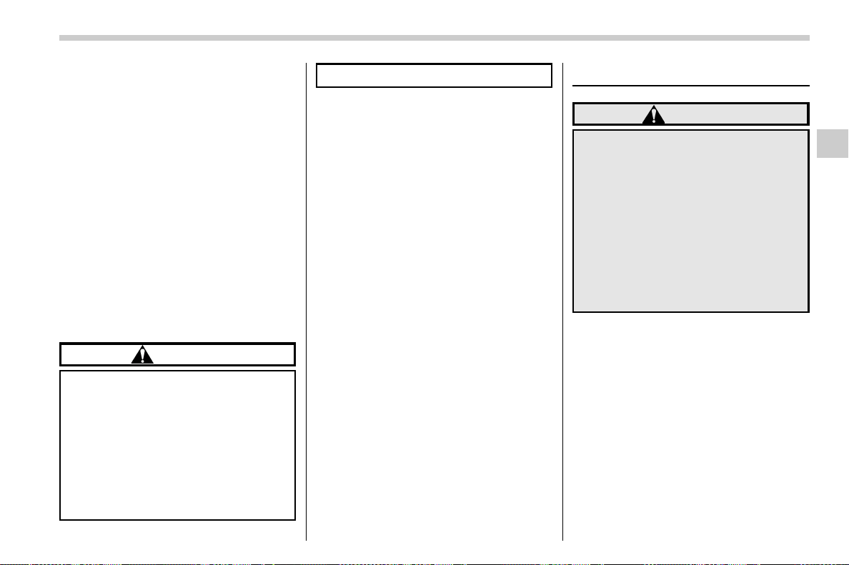
(227,1)
北米Model "A1700BE-B" EDITED: 2017/ 10/ 11
outside mirrors have been cleared and the
windshield wiper blade rubbers have been
deiced completely before that time, press
the control switch to turn them off. If
defrosting, defogging or deicing is not
complete, you have to press the control
switch to turn them on again.
It is possible for the defogger and deicer
system to be set to continuous operation
mode by a SUBARU dealer. Consult your
SUBARU dealer for details. Also, you can
change the setting using the multi-function
display (color LCD). For details, refer to
“Defogger setting” F3-61.
If the battery voltage drops below the
permissible level, continuous operation of
the defogger and deicer system is can-
celed and the system stops operating.
CAUTION
. To prevent the battery from being
discharged, do not operate the
defogger and deicer system con-
tinuously for any longer than
necessary.
. Do not use sharp instruments or
window cleaner containing abra-
sives to clean the inner surface of
the rear window. They may da-
mage the conductors printed on
the window.
NOTE
. Turn on the defogger and deicer
system if the wipers are frozen to the
windshield.
. If the windshield is covered with
snow, remove the snow so that the
windshield wiper deicer works effec-
tively.
. While the defogger and deicer sys-
tem is in the continuous operation
mode:
– If the vehicle speed remains at 9
mph (15 km/h) or lower for 15
minutes, the windshield wiper dei-
cer system automatically stops op-
erating. However, the rear window
defogger system and outside mirror
defogger system maintain continu-
ous operation in this condition.
– If the vehicle battery voltage
drops below the permissible level,
continuous operation of the defog-
ger system and deicer system is
canceled and the system stops
operating.
Tilt/telescopic steering wheel
WARNING
. Do not adjust the steering wheel
tilt/telescopic position while driv-
ing. This may cause loss of
vehicle control and result in per-
sonal injury.
. If the lever cannot be raised to the
fixed position, adjust the steering
wheel again. It is dangerous to
drive without locking the steering
wheel. This may cause loss of
vehicle control and result in per-
sonal injury.
– CONTINUED –
Instruments and controls/Tilt/telescopic steering wheel
3-85
3
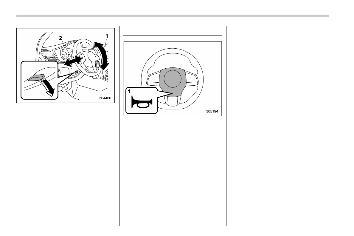
(228,1)
北米Model "A1700BE-B" EDITED: 2017/ 10/ 11
1) Tilt adjustment
2) Telescopic adjustment
1. Adjust the seat position. Refer to “ Front
seats” F1-2.
2. Pull the tilt/telescopic lock lever down.
3. Move the steering wheel to the desired
level.
4. Pull the lever up to lock the steering
wheel in place.
5. Make sure that the steering wheel is
securely locked by moving it up and down,
and forward and backward.
Horn
1) Horn mark
To sound the horn, push the horn pad.
Instruments and controls/Horn
3-86

(231,1)
北米Model "A1700BE-B" EDITED: 2017/ 10/ 11
Ventilator control .................................................... 4-2
Center and side ventilators .................................... 4-2
Climate control panel ............................................. 4-3
Type A ................................................................... 4-3
Type B ................................................................... 4-4
Automatic climate control operation..................... 4-5
Sensors ................................................................. 4-5
Manual climate control operation.......................... 4-6
Airflow mode selection........................................... 4-6
Temperature control............................................... 4-7
Fan speed control.................................................. 4-8
Air conditioner control ........................................... 4-8
Air inlet selection ................................................... 4-8
Defrosting ................................................................ 4-9
Operating tips for heater and air conditioner ...... 4-9
Cleaning ventilation grille ....................................... 4-9
Efficient cooling after parking in direct sunlight ......4-9
Lubrication oil circulation in the refrigerant
circuit.................................................................. 4-9
Checking air conditioning system before summer
season ................................................................ 4-9
Cooling and dehumidifying in high humidity and
low temperature weather conditions................... 4-10
Air conditioner compressor shut-off when engine
is heavily loaded................................................ 4-10
Refrigerant for your climate control system .......... 4-10
Air filtration system.............................................. 4-10
Replacing a cabin air filter .................................... 4-11
Climate control
4
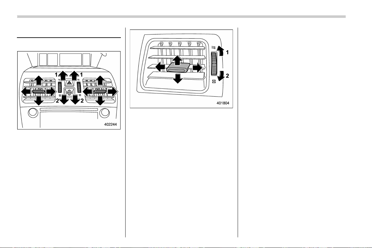
(232,1)
北米Model "A1700BE-B" EDITED: 2017/ 10/ 11
Ventilator control
& Center and side ventilators
Center ventilators
1) Open
2) Close
Side ventilators
1) Open
2) Close
To adjust the flow direction, move the tab.
To open or close the ventilator, turn the
thumb-wheel up or down.
Climate control/Ventilator control
4-2
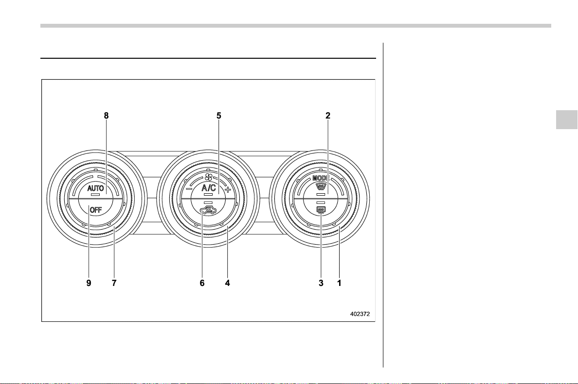
(233,1)
北米Model "A1700BE-B" EDITED: 2017/ 10/ 11
Climate control panel
& Type A
1) Airflow mode selection dial (Refer to
“Airflow mode selection” F4-6.)
2) Defroster button (Refer to “Airflow mode
selection” F4-6.)
3) Rear window defogger button (Refer to
“Defogger and deicer” F3-84.)
4) Fan speed control dial (Refer to “Fan
speed control” F4-8.)
5) Air condi tioner button (Refe r to “Air
conditioner control” F4-8.)
6) Air inlet selection button (Refer to “Air
inlet selection” F4-8.)
7) Temperature control dial (Refer to “Auto-
matic climate control operation” F4-5
and/or “Temperature control” F4-7.)
8) AUTO button (Refer to “Automatic cli-
mate control operation” F4-5.)
9) OFF button (Refer to “Automatic climate
control operation” F4-5.)
– CONTINUED –
Climate control/Climate control panel
4-3
4
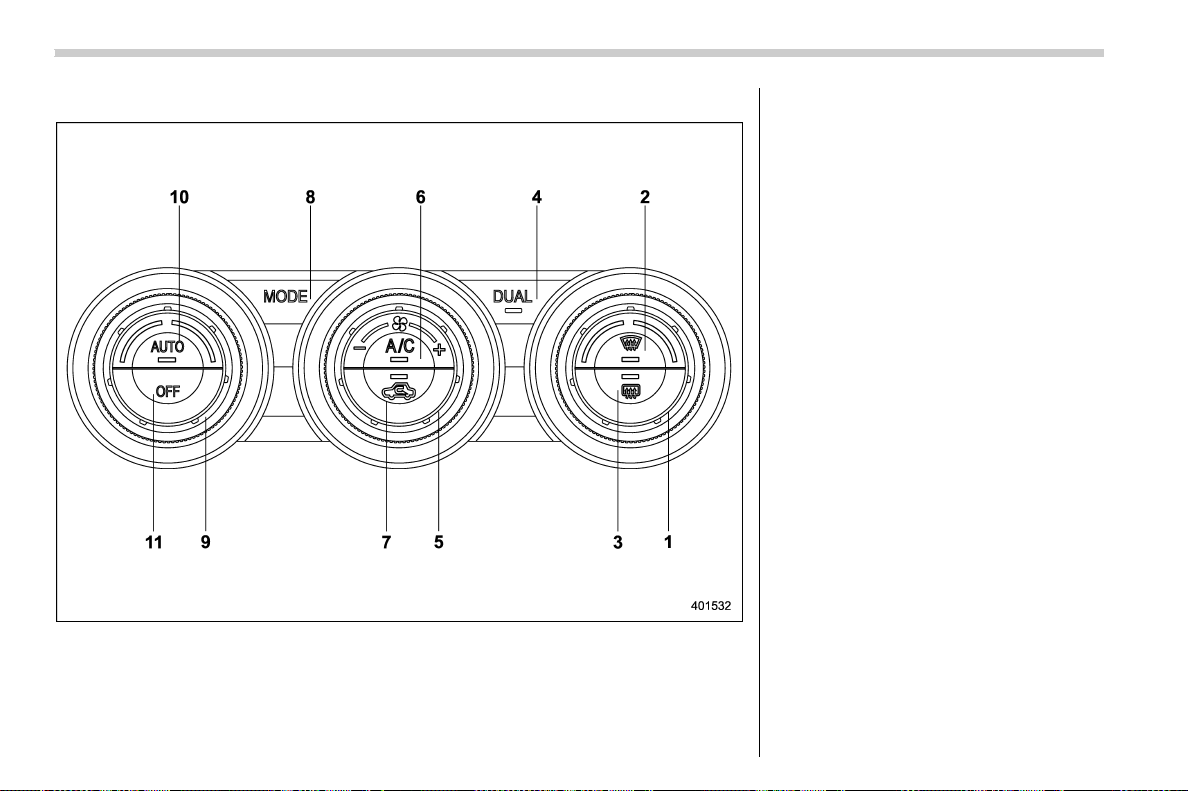
(234,1)
北米Model "A1700BE-B" EDITED: 2017/ 10/ 11
& Type B
1) Temperature control dial (Refer to “Auto-
matic climate control operation” F4-5
and/or “Temperature control” F4-7.)
2) Defroster button (Refer to “Airflow mode
selection” F4-6.)
3) Rear window defogger button (Refer to
“Defogger and deicer” F3-84.)
4) DUAL mode button (Refer to ““DUAL”
mode (type B)” F4-7.)
5) Fan speed control dial (Refer to “Fan
speed control” F4-8.)
6) Air condi tioner button (Refe r to “Air
conditioner control” F4-8.)
7) Air inlet selection button (Refer to “Air
inlet selection” F4-8.)
8) Airflow mode selection button (Refer to
“Airflow mode selection” F4-6.)
9) Temperature control dial (Refer to “Auto-
matic climate control operation” F4-5
and/or “Temperature control” F4-7.)
10) AUTO button (Refer to “Automatic cli-
mate control operation” F4-5.)
11) OFF button (Refer to “Automatic climate
control operation” F4-5.)
Climate control/Climate control panel
4-4
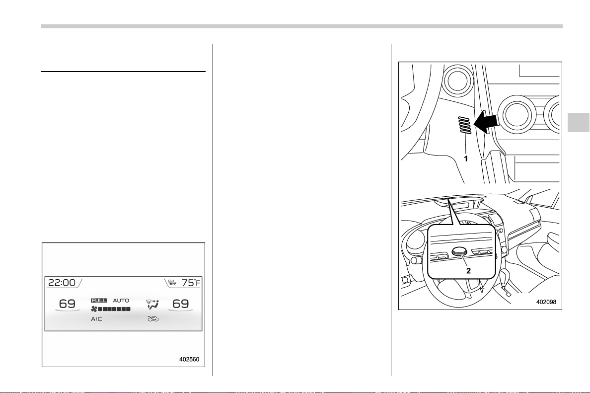
(235,1)
北米Model "A1700BE-B" EDITED: 2017/ 10/ 11
Automatic climate control
operation
When this mode is selected, the fan speed,
airflow distribution, air-inlet control, and air
conditioner compressor operation are
automatically controlled. To activate this
mode, perform the following.
NOTE
. Operate the automatic climate con-
trol system when the engine is running.
. Even when cooling is not necessary,
the air conditioner compressor will
automatically turn on if the temperature
is set much lower than the current
outlet air temper ature. Even in thi s
case, the “A/C” indicator light on the
control panel illuminates.
1. Depress the “AUTO” button. The in-
dicator “FULL AUTO” on the display
illuminates.
2. Set the preferred temperature using
the temperature control dial.
NOTE
. The controllable temperature range
may vary depending on the regional
specifications of the vehicle.
. During FULL AUTO mode operation,
a small amount of air may flow from the
foot outlets when ventilation mode is
displayed.
. If you operate any of the buttons on
the control panel other than the “OFF ”
button, rear window defogger button
and temperature control dial(s) during
FULL AUTO mo de opera tion, t he
“FULL” indicator on the control panel
will turn off and the “AUTO” indicator
will remain illuminated. You can then
manually control the system as desired
using the button you operated. To
change the system back to the FULL
AUTO mode, press the “AUTO” button.
. When the climate control system
turns off, the air inlet is fixed to the
outside air mode.
To turn off the climate control system,
press the “OFF” button.
& Sensors
1) Interior air temperature sensor
2) Solar sensor
The automatic climate control system
employs several sensors.
The sensors are located as follows.
– CONTINUED –
Climate control/Automatic climate control operation
4-5
4
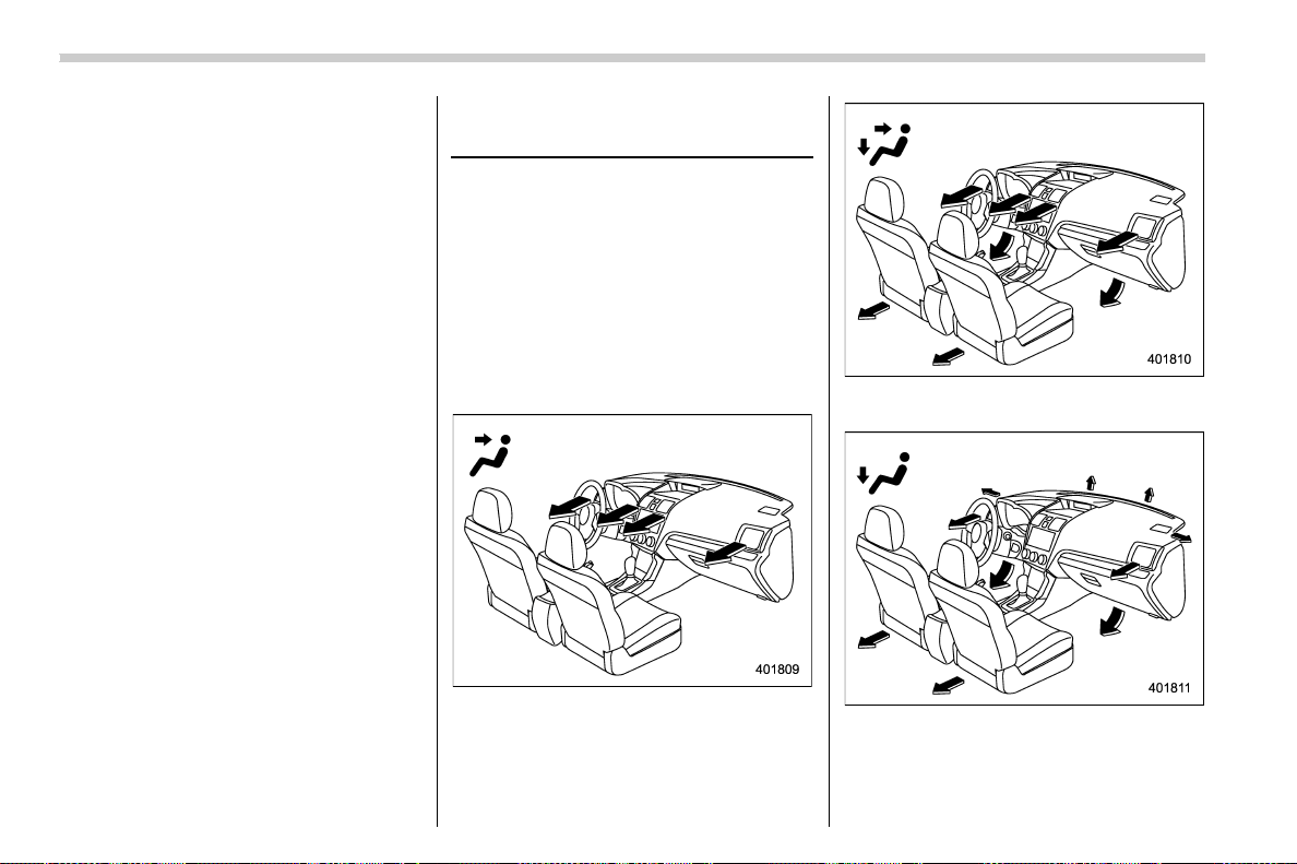
(236,1)
北米Model "A1700BE-B" EDITED: 2017/ 10/ 11
– Solar sensor: beside the windshield
defroster grille
– Interior air temperature sensor: next to
the steering column
– Outside temperature sensor: near the
front bumper opening
These sensors are delicate. If they are not
treated properly and become damaged,
the system may not be able to control the
interior temperature correctly. To avoid
damaging the sensors, observe the follow-
ing precautions.
– Do not subject the sensors to impact.
– Keep water away from the sensors.
– Do not cover the sensors.
Manual climate control op-
eration
& Airflow mode selection
To select the airflow mode:
Type A: Turn the airflow mode selection
dial.
Type B: Press the airflow mode selection
button.
To select the defrost mode:
Press the defroster button.
Airflow modes are as follows.
(Ventilation): Instrument panel outlets
(Bi-level): Instrument panel outlets and
foot outlets
(Heat): Foot outlets, both side outlets of
the instrument panel and some through
windshield defroster outlets (A small
amount of air flows to the windshield and
Climate control/Manual climate control operation
4-6
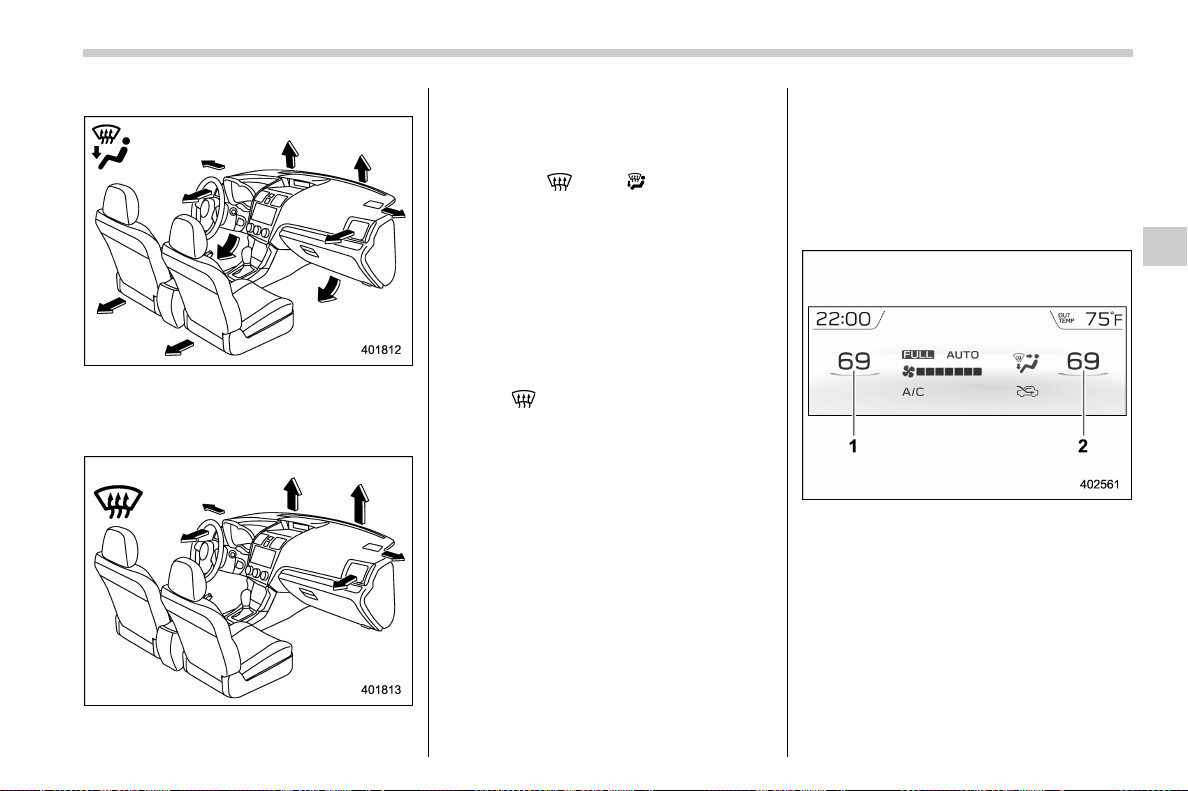
(237,1)
北米Model "A1700BE-B" EDITED: 2017/ 10/ 11
both side windows to prevent fogging.)
(Heat-def): Windshield defroster outlets,
foot outlets and both side outlets of the
instrument panel (Refer to “Defrosting”
F4-9.)
(Defrost): Windshield defroster outlets
and both side outlets of the instrument
panel (Refer to “Defrosting” F4-9.)
NOTE
When the “ ” or “ ” mode is se-
lected, the air conditioner compressor
operates automatically regardless of
the position of the air conditioner
button to defrost the windshield more
quickly. However the indicator on the
air conditioner button will not illumi-
nate. At the same time, the air inlet
selection is automatically set to the
outside air mode. After defrosting the
windshield by pressing the defroster
button “
”, pressing the button again
returns the system to the setting that
had been selected before the defroster
was activated.
& Temperature control
Turn the temperature control dial to set the
preferred interior temperature. With the
dial set to your preferred temperature, the
system automatically adjusts the tempera-
ture of air supplied from the outlets so that
the preferred temperature is achieved and
maintained.
If the dial is turned fully counterclockwise,
the system provides maximum cooling
performance. If the dial is turned fully
clockwise, the system provides maximum
heating performance.
NOTE
The controllable temperature range
may vary depending on the regional
specifications of the vehicle.
! “DUAL” mode (type B)
1) Driver’s side temperature
2) Front passenger’s side temperature
You can change the setting of the driver’s
side and front passenger’s side tempera-
ture independently by selecting the
“DUAL” mode.
Perform either of the following procedures
to select the “DUAL” mode.
. Press the “DUAL” button
. Turn the passenger’s side temperature
– CONTINUED –
Climate control/Manual climate control operation
4-7
4
(238,1)
北米Model "A1700BE-B" EDITED: 2017/ 10/ 11
control dial
Press the “DUAL” button to cancel the
“DUAL” mode.
When the “DUAL” mode is selected:
Turn the driver’s side dial to set the driver’s
side temperature. Turn the front passen-
ger’s side dial to set the front passenger’s
side temperature.
When the “DUAL” mode is canceled:
Turn the driver’s side dial to set the desired
temperature.
When the “DUAL” mode is canceled, only
the driver’s side temperature is displayed.
& Fan speed control
The fan operates only when the ignition
switch is in the “ON” position. Turn the fan
speed control dial to select the preferred
fan speed.
& Air conditioner control
The air conditioner operates only when the
engine is running.
Press the air conditioner button while the
fan is in operation to turn on the air
conditioner. When the air conditioner is
on, the “A/C” indicator light illuminates.
To turn off the air conditioner, press the
button again.
NOTE
For efficient defogging or dehumidify-
ing in cold weather, turn on the air
conditioner. However, if the ambient
temperature decreases to approxi-
mately 328 F(08C), the air conditioner
compressor will stop operating.
& Air inlet selection
Select the air inlet by pressing the air inlet
selection button.
ON position (recirculation): Interior air is
recirculated inside the vehicle. Press the
air inlet selection button to the ON position
for fast cooling with the air conditioner or
when driving on a dusty road.
OFF position (outside air): Outside air is
drawn into the passenger compartment.
Press the air inlet selection button to the
OFF position when the interior has cooled
to a comfortable temperature and the road
is no longer dusty.
WARNING
Continued operation in the ON posi-
tion may fog up the windows. Switch
to the OFF position as soon as the
outside conditions are no longer
dusty.
NOTE
When the battery is disconnected or the
battery voltage drops, the air inlet
selection operation indicator light may
blink. This does not indicate a malfunc-
tion. However, if the indicator light
blinks every time you start the engine,
a malfunction may occur in the elec-
trical circuit. Have the vehicle in-
spected at the nearest SUBARU dealer.
Climate control/Manual climate control operation
4-8
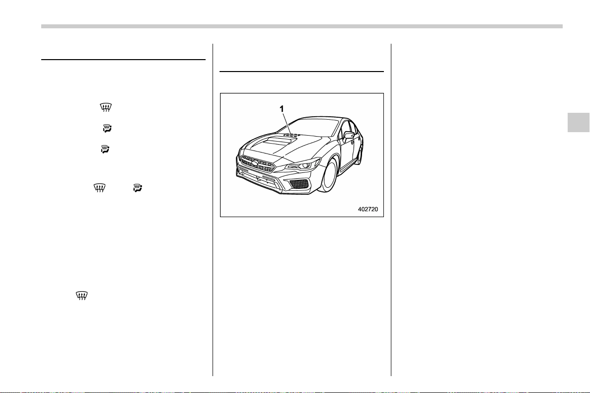
(239,1)
北米Model "A1700BE-B" EDITED: 2017/ 10/ 11
Defrosting
Perform either of the following operations
to defrost or to dehumidify the windshield
and front door windows.
. Select the “
” mode by pressing the
defroster button (both types A and B)
. Select the “
” mode by turning the
airflow mode selection dial (type A)
. Select the “
” mode by pressing the
airflow mode selection button (type B)
NOTE
When the “ ” or “ ” mode is se-
lected, the air conditioner compressor
operates automatically regardless of
the position of the air conditioner
button to defrost the windshield more
quickly. However the indicator on the
air conditioner button will not illumi-
nate. At the same time, the air inlet
selection is automatically set to the
outside air mode. After defrosting the
windshield by pressing the defroster
button “
”, pressing the button again
returns the system to the setting that
had been selected before the defroster
was activated.
Operating tips for heater and
air conditioner
& Cleaning ventilation grille
1) Front ventilation inlet grille
Always keep the front ventilation inlet grille
free of snow, leaves, or other obstructions
to ensure efficient heating and defrosting.
Since the condenser is located in front of
the radiator, this area should be kept clean
because cooling performance is impaired
by any accumulation of insects and leaves
on the condenser.
& Efficient cooling after parking
in direct sunlight
After parking in direct sunlight, drive with
the windows open for a few minutes to
allow outside air to circula te into the
heated interior. This results in quicker
cooling by the air conditioner. Keep the
windows closed during the operation of the
air conditioner for maximum cooling effi-
ciency.
& Lubrication oil circulation in
the refrigerant circuit
Operate the air conditioner compressor at
a low engine speed (at idle or low driving
speeds) a few minutes each month during
the off-season to circulate its oil.
& Checking air conditioning
system before summer sea-
son
Check the air conditioner unit for refriger-
ant leaks, hose conditions, and proper
operation each spring. Have the air con-
ditioning system checked by your
SUBARU dealer.
– CONTINUED –
Climate control/Defrosting
4-9
4
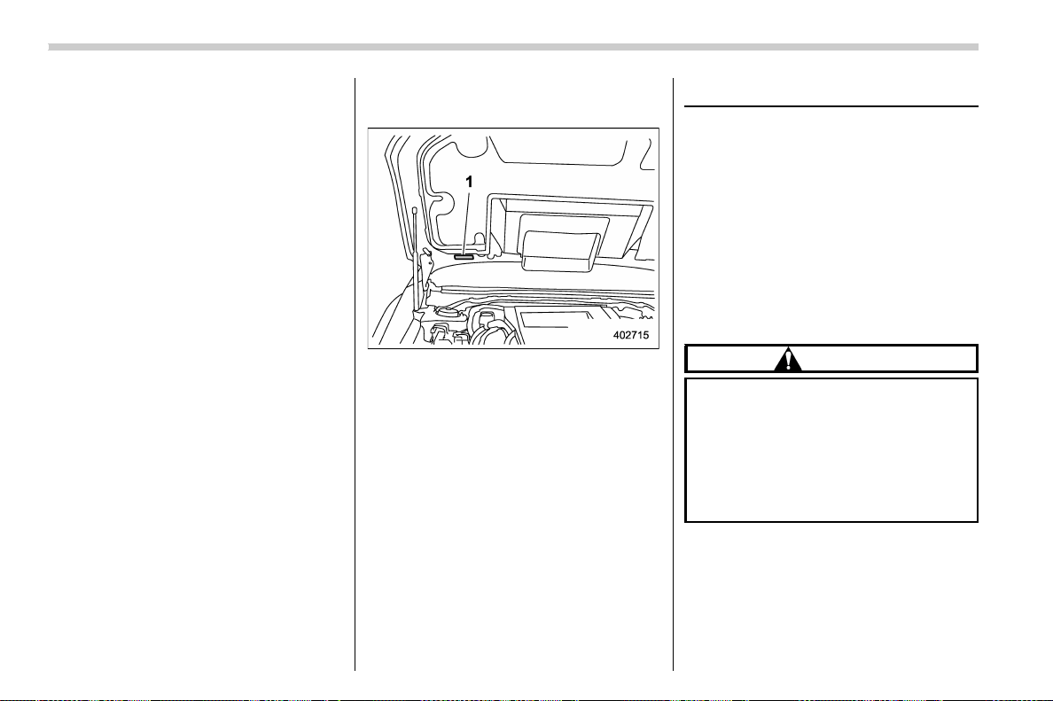
(240,1)
北米Model "A1700BE-B" EDITED: 2017/ 10/ 11
& Cooling and dehumidifying in
high humidity and low tem-
perature weather conditions
Under certain weather conditions (high
relative humidity, low temperatures, etc.) a
small amount of water vapor emission
from the air outlets may be noticed. This
condition is normal and does not indicate
any problem with the air con ditio ning
system.
& Air conditioner compressor
shut-off when engine is
heavily loaded
To improve acceleration and gas mileage,
the air conditioner compressor is designed
to temporarily shut off during air condi-
tioner operation whenever the accelerator
is fully depressed such as during rapid
acceleration or when driving up a steep
incline.
& Refrigerant for your climate
control system
1) Air conditioner label
Your air conditioner uses ozone friendly
refrigerant HFC134a (as shown on the air
conditioner label). Therefore, the method
of adding, changing o r checki ng the
refrigerant is different from the method
for CFC12 (freon). Consult your SUBARU
dealer for service. Repairs needed as a
result of using the wrong refrigerant are not
covered under warranty.
Air filtration system
Your vehicle’s air conditioning system is
equipped with an air filtration system.
Replace the cabin air filter element ac-
cording to the replacement schedule found
in the “Warranty and Maintenance Book-
let”. This schedule should be followed to
maintain the filter’s dust collection ability.
Under extremely dusty conditions, the filter
should be replaced more frequently. Have
your filter checked or replaced by your
SUBARU dealer. For replacement, use
only a genuine SUBARU air filter kit.
CAUTION
Contact your SUBARU dealer if the
following occurs, even if it is not yet
time to change the filter:
. Reduction of the airflow through
the vents.
. Windshield gets easily fogged or
misted.
NOTE
The filter can influence the air condi-
tioning, heating and defroster perfor-
mance if not properly maintained.
Climate control/Air filtration system
4-10
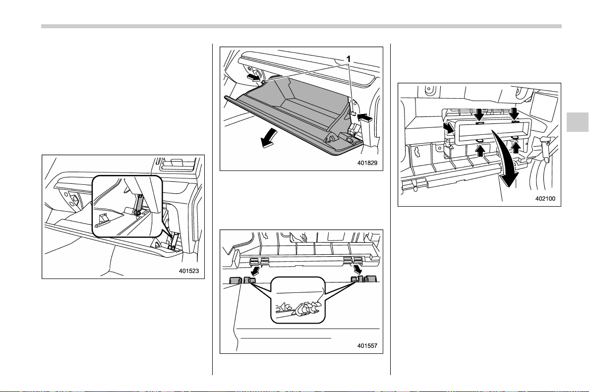
(241,1)
北米Model "A1700BE-B" EDITED: 2017/ 10/ 11
& Replacing a cabin air filter
1. Remove the glove box.
NOTE
We recommend that you take measures
to protect the center console with
masking tape first, so that you avoid
scratching the center console with the
glove box.
(1) Open the glove box.
(2) Remove the damper shaft from the
glove box.
1) Stopper
(3) Push both sides of the glove box
inside to unlock the stoppers and then
pull down the glove box as far as it will
go.
(4) Pull out the glove box horizontally
and remove the hinge portion. When
doing this, be careful not to damage
the hinge.
2. Remove the cabin air filter according to
the following procedure in order to prevent
dust on the air cleaner from falling to the
inside of its housing.
(1) Push in the four stoppers to unlock,
and then slowly pull out the filter 4 in
(10 cm) from the housing.
(2) Completely pull out the filter by
gently tilting the front side of the filter
downward.
– CONTINUED –
Climate control/Air filtration system
4-11
4
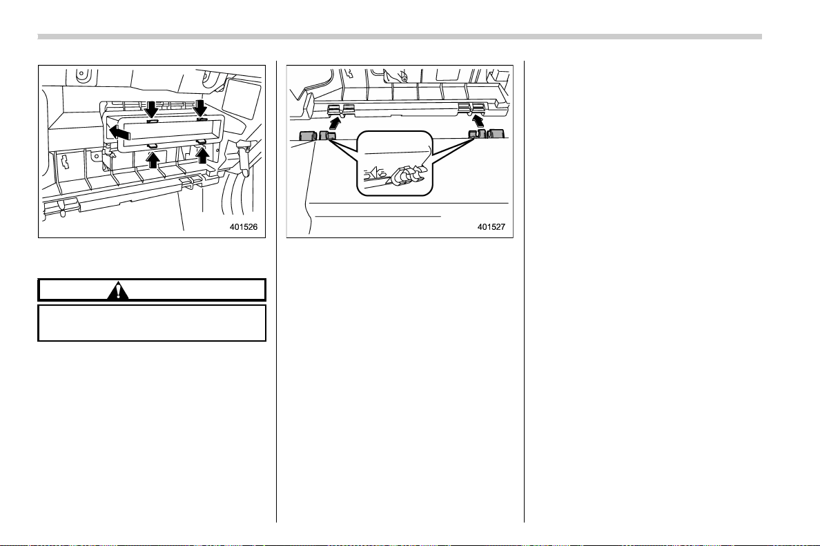
(242,1)
北米Model "A1700BE-B" EDITED: 2017/ 10/ 11
3. Replace the cabin air filter element
with a new one.
CAUTION
The arrow mark on the filter must
point UP.
4. Reinstall the glove box, and connect
the damper shaft.
5. Close the glove box.
Climate control/Air filtration system
4-12

(245,1)
北米Model "A1700BE-B" EDITED: 2017/ 10/ 11
Antenna ................................................................... 5-2
Roof antenna ......................................................... 5-2
Audio set ................................................................. 5-2
Base display audio set (if equipped)....................... 5-3
SUBARU STARLINK
TM
7.0 Multimedia Plus audio
set (U.S. spec. models only, if equipped) .............. 5-5
Tips for operating the audio/visual system ............. 5-6
Basic information before use ................................5-14
Basic operation.....................................................5-17
Unit settings .........................................................5-18
SUBARU STARLINK (if equipped) ..........................5-25
AM/FM radio .........................................................5-27
SiriusXM Satellite Radio (if equipped).................... 5-36
aha
TM
by HARMAN................................................5-42
Pandora
®
(if equipped)..........................................5-48
CD........................................................................5-51
USB memory ........................................................ 5-53
iPod...................................................................... 5-54
Bluetooth audio .................................................... 5-56
AUX......................................................................5-59
Steering switches for audio ................................. 5-61
Bluetooth
®
settings .............................................. 5-64
Regulatory information ......................................... 5-64
Registering/connecting Bluetooth
®
device.............5-64
Setting Bluetooth details.......................................5-67
Hands-free phone system.................................... 5-69
Control screen......................................................5-70
Registering/connecting a Bluetooth phone ............5-71
Using the phone switch/microphone .....................5-71
How to change the hands-free phone system........ 5-72
Making a call ........................................................5-72
Receiving a call .................................................... 5-75
Talking on the phone ............................................5-76
Phone settings ..................................................... 5-77
Voice command system ....................................... 5-79
Using the voice command system ........................ 5-79
Voice command system operation.........................5-81
Command list .......................................................5-83
What to do if... ...................................................... 5-87
Troubleshooting ................................................... 5-87
Appendix ............................................................... 5-91
Certification.......................................................... 5-91
Certification for the Hands-free system .................5-91
Certification for Mexico models.............................5-92
Audio
5
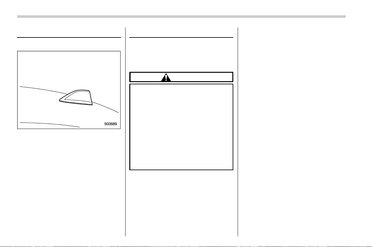
(246,1)
北米Model "A1700BE-B" EDITED: 2017/ 10/ 11
Antenna
& Roof antenna
The shark-fin type roof antenna is installed
in the center at the rear of the roof.
Audio set
Your vehicle may be equipped with one of
the following audio sets. Refer to the
pages indicated in this section for operat-
ing details.
CAUTION
. Always consult your SUBARU
dealer before installing a citizen
band radio or other transmitting
device in your vehicle. Such
devices may cause the electronic
control system to malfunction if
they are incorrectly installed or if
they are not suited for the vehi-
cle.
. To prevent the battery from being
discharged, do not leave the
audio/visual system on when the
engine is not running.
NOTE
. If a cell phone is placed near the
audio set, it may cause the audio set to
emit noise when the phone receives
calls. This noise does not indicate an
audio set malfunction. Note that a cell
phone should not be placed near the
audio set.
. Some functions may not be available
depending on the market and specifi-
cations of your vehicle.
. The images shown in this Owner’s
Manual are sample images. The actual
images may vary depending on the
market and specifications of your ve-
hicle.
Audio/Antenna
5-2
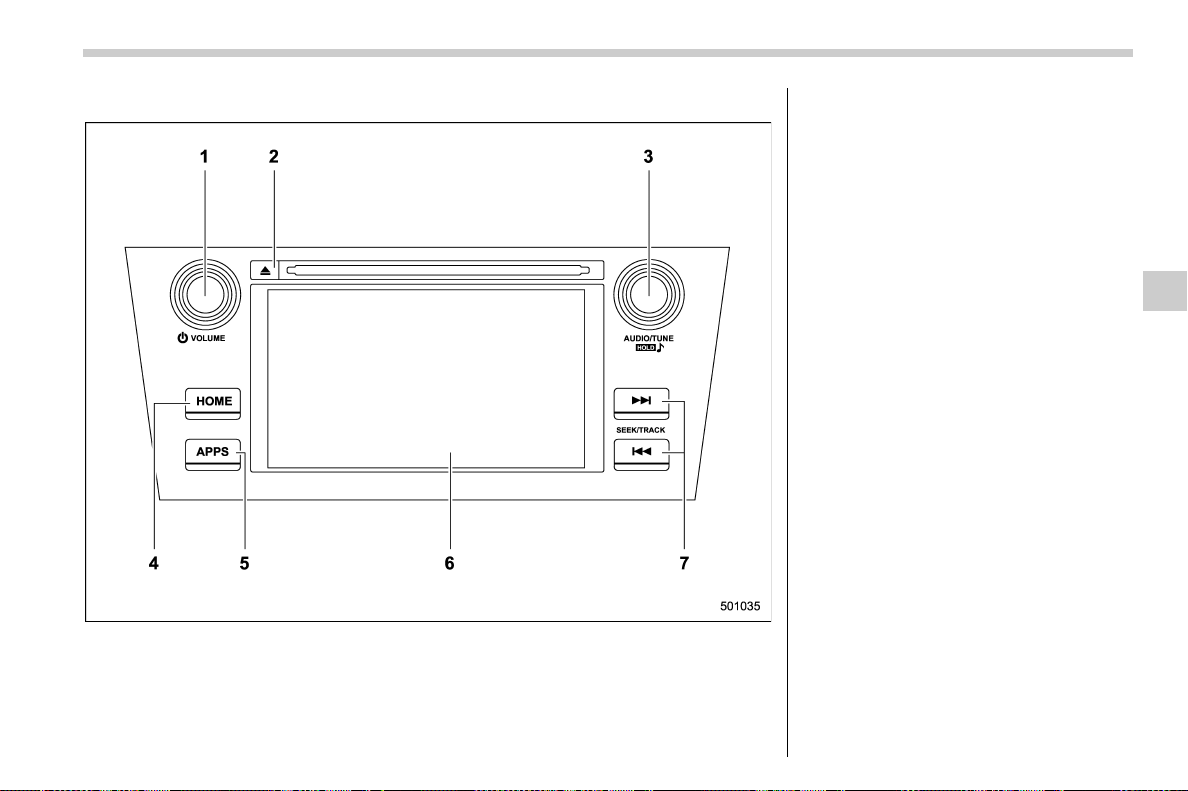
(247,1)
北米Model "A1700BE-B" EDITED: 2017/ 10/ 11
& Base display audio set (if equipped)
1) Power/VOLUME knob
2) Eject button
3) AUDIO/TUNE knob
4) HOME button
5) APPS button
6) Display
7) SEEK/TRACK buttons
The audio set will operate only when the
ignition switch is in the “ACC” or “ON”
position.
. Power and audio controls: refer to
“Basic operation” F5-17.
. SUBARU STARLINK (if equipped):
refer to “SUBARU STARLINK” F5-25.
. Radio operation: refer to “AM/FM radio”
F5-27.
. Satellite radio operation (if equipped):
refer to “SiriusXM Satellite Radio” F5-36.
. aha
TM
: refer to “aha
TM
by HARMAN”
F5-42.
. Pandora
®
(if equipped): refer to “Pan-
dora
®
” F5-48.
. CD (compact disc) player operation:
refer to “CD” F5-51.
. USB storage device: refer to “USB
memory” F5-53.
. iPod operation: refer to “iPod” F5-54.
. Bluetooth
®
audio: refer to “Bluetooth
audio” F5-56.
. Auxiliary input jack: refer to “AUX” F5-
59.
. Hands-free phone system: refer to
“Hands-free phone system” F5-69.
– CONTINUED –
Audio/Audio set
5-3
5

(248,1)
北米Model "A1700BE-B" EDITED: 2017/ 10/ 11
NOTE
HD Radio
TM
Technology (if equipped)
should be included as a feature in the
base display audio set.
This display audio set is referred to as
follows.
. U.S. customers: SUBARU
STARLINK
TM
6.2 Multimedia
. Canadian customers: 6.2-inch infotain-
ment system
Audio/Audio set
5-4
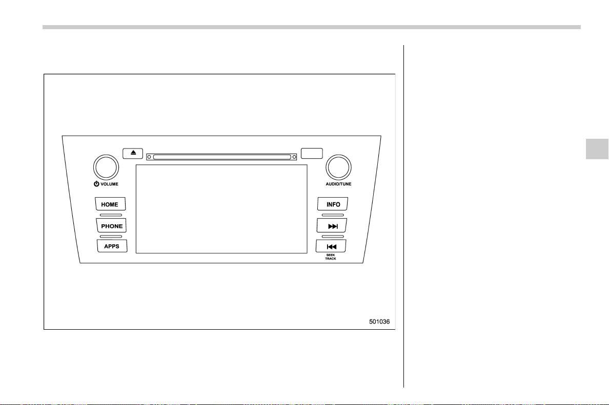
(249,1)
北米Model "A1700BE-B" EDITED: 2017/ 10/ 11
& SUBARU STARLINK
TM
7.0 Multimedia Plus audio set (U.S. spec.
models only, if equipped)
The audio set will operate only when the
ignition switch is in the “ACC” or “ON”
position.
For details about how to use the SUBARU
STARLINK
TM
7.0 Multimedia Plus audio
set, refer to the SUBARU STARLINK
TM
7.0
Multimedia Plus or SUBARU
STARLINK
TM
7.0 Multimedia Navigation
Owner’s Manual.
NOTE
HD Radio Technology should be in-
cluded as a feature in the SUBARU
STARLINK
TM
7.0 Multimedia Plus audio
set.
– CONTINUED –
Audio/Audio set
5-5
5
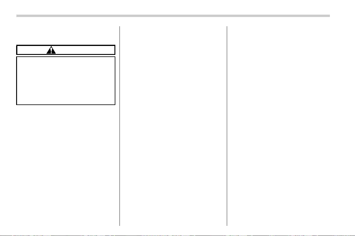
(250,1)
北米Model "A1700BE-B" EDITED: 2017/ 10/ 11
& Tips for operating the audio/
visual system
CAUTION
To avoid damage to the audio/visual
system:
. Be careful not to spill beverages
over the audio/visual system.
. Do not put anything other than an
appropriate disc into the disc
slot.
NOTE
The use of a cell phone inside or near
the vehicle may cause a noise from the
speakers of the audio/visual system
which you are listening to. However,
this does not indicate a malfunction.
! Radio
Usually, a problem with radio reception
does not mean there is a problem with the
radio — it is just the normal result of
conditions outside the vehicle.
For example, nearby buildings and terrain
can interfere with FM reception. Power
lines or phone wires can interfere with AM
signals. And of course, radio signals have
a limited range. The farther the vehicle is
from a station, the weaker its signal will be.
In addition, reception conditions change
constantly as the vehicle moves.
Here, some common reception problems
that probably do not indicate a problem
with the radio are described.
! FM
Fading and drifting stations: Generally, the
effective range of FM is about 25 miles (40
km). Once outside this range, you may
notice fading and drifting, which increase
with the distance from the radio transmit-
ter. They are often acc ompanied by
distortion.
Multi-path: FM signals are reflective, mak-
ing it possible for 2 signals to reach the
vehicle’s antenna at the same time. If this
happens, the signals will cancel each other
out, causing a momentary flutter or loss of
reception.
Static and fluttering: These occur when
signals are blocked by buildings, trees or
other large objects. Increasing the bass
level may reduce static and fluttering.
Station swapping: If the FM signal being
listened to is interrupted or weakened, and
there is another strong station nearby on
the FM band, the radio may tune in the
second station until the original signal can
be picked up again.
! AM
Fading: AM broadcasts are reflected by
the upper atmosphere — especially at
night. These reflected signals can interfere
with those received directly from the radio
station, causing the radio station to sound
alternately strong and weak.
Station interference: When a reflected
signal and a signal received directly from
a radio station are very nearly the same
frequency, they can interfere with each
other, making it difficult to hear the broad-
cast.
Static: AM is easily affected by external
sources of electrical noise, such as high
tension power lines, lightening or electrical
motors. This results in static.
! SiriusXM (if equipped)
. Cargo lo aded on the roof luggag e
carrier, especially metal objects, may
adversely affect the reception of SiriusXM
Satellite Radio.
. Alternation or modifications carried out
without appropriate authorization may in-
validate the user’s right to operate the
equipment.
Audio/Audio set
5-6

(251,1)
北米Model "A1700BE-B" EDITED: 2017/ 10/ 11
! CD player and disc
. This CD player is intended for use with
4.7 in. (12 cm) discs only.
. Extremely high temperatures can keep
the CD player from working. On hot days,
use the air conditioning system to cool the
inside of the vehicle before using the
player.
. Bumpy roads or other vibrations may
make the CD player skip.
. If moisture gets into the CD player, the
discs may not be able to be played.
Remove the discs from the player and
wait until it dries.
WARNING
CD players use an invisible laser
beam which could cause hazardous
radiation exposure if directed out-
side the unit. Be sure to operate the
player correctly.
Audio CDs
. Use only discs marked as shown
above. The following products may not
be playable on your player:
– SACD
– dts CD
– Copy-protected CD
– Video CD
Special shaped discs
Transparent/translucent discs
– CONTINUED –
Audio/Audio set
5-7
5
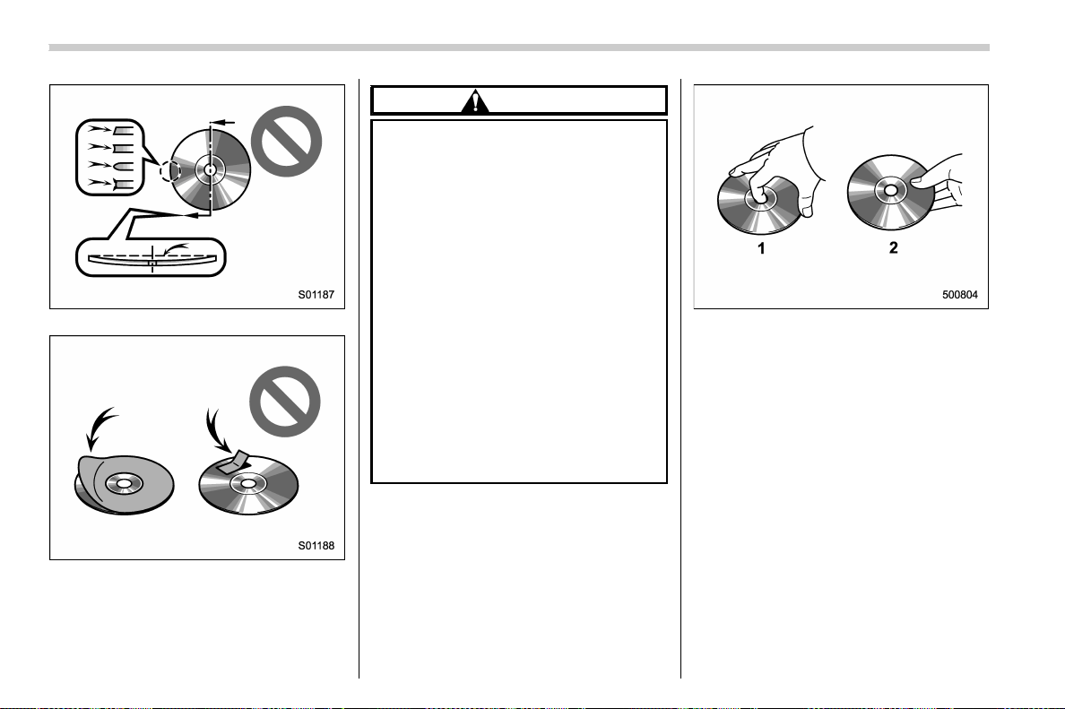
(252,1)
北米Model "A1700BE-B" EDITED: 2017/ 10/ 11
Low quality discs
Labeled discs
CAUTION
. Do not use special shaped, trans-
parent/translucent, low quality or
labeled di scs such as those
shown in the illustrations. The
use of such discs may damage
the player, or it may be impossi-
ble to eject the disc.
. This system is not designed for
use of Dual Discs. Do not use
Dual Discs because they may
cause damage to the player.
. Do not use discs with a protection
ring. The use of such discs may
damage the player, or it may be
impossible to eject the disc.
. Do not use printable discs. The
use of such discs may damage
the player, or it may be impossi-
ble to eject the disc.
1) Correct
2) Wrong
. Handle discs carefully, especially when
inserting them. Hold them on the edge and
do not bend them. Avoid getting finger-
prints on them, particularly on the shiny
side.
. Dirt, scratches, warping, pin holes or
other disc damage could cause the player
to skip or to repeat a section of a track. (To
see a pin hole, hold the disc up to the light.)
. Remove discs from the players when
not in use. Store them in their plastic cases
away from moisture, heat and direct sun-
light.
Audio/Audio set
5-8
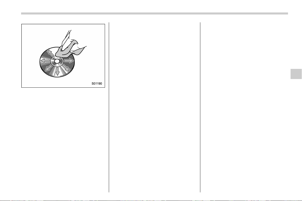
(253,1)
北米Model "A1700BE-B" EDITED: 2017/ 10/ 11
To clean a disc: Wipe it with a soft, lint-
free cloth that has been dampened with
water. Wipe in a straight line from the
center to the edge of the disc (not in
circles). Dry it with another soft, lint-free
cloth. Do not use a conventional record
cleaner or anti-static device.
! CD-R/RW discs
. CD-R/CD-RW discs that have not been
subject to the “finalizing process ” (a
process that allows discs to be played on
a conventional CD player) cannot be
played.
. It may not be possible to play CD-R/CD-
RW discs recorded on a music CD
recorder or a personal computer because
of disc characteristics, scratches or dirt on
the disc, or dirt, condensation, etc. on the
lens of the unit.
. It may not be possible to play discs
recorded on a personal computer depend-
ing on the application settings and the
environment. Re cord with the corre ct
format. (For details, contact the appropri-
ate application manufacturers of the appli-
cations.)
. CD-R/CD-RW discs may be damaged
by direct exposure to sunlight, high tem-
peratures or other storage conditions. The
unit may be unable to play some damaged
discs.
. If you insert a CD-RW disc into the
player, playback will begin more slowly
than with a conventional CD or CD-R disc.
. Recordings on CD-R/CD-RW cannot
be played using the DDCD (Double Den-
sity CD) system.
! USB memory device
. USB communication formats: USB
1.1/2.0 HS (480 Mbps) and FS (12 Mbps)
. File formats: FAT 16/32
. Correspondence class: Mass storage
class
! iPod
The following i Pod, iPod n ano, iPod
classic, iPod touch and iPhone devices
can be used with this system.
Made for
. iPod touch (5th generation)*
. iPod touch (4th generation)
. iPod touch (3rd generation)
. iPod touch (2nd generation)
. iPod touch (1st generation)
. iPod classic
. iPod nano (7th generation)*
. iPod nano (6th generation)*
. iPod nano (5th generation)
. iPod nano (4th generation)
. iPod nano (3rd generation)
. iPod nano (2nd generation)*
. iPod nano (1st generation)*
. iPhone 5s*
. iPhone 5c*
. iPhone 5*
. iPhone 4s
. iPhone 4
. iPhone 3GS
. iPhone 3G
. iPhone
*: iPod video not supported
Depending on differences between mod-
els or software versions etc., some models
might be incompatible with this system.
– CONTINUED –
Audio/Audio set
5-9
5
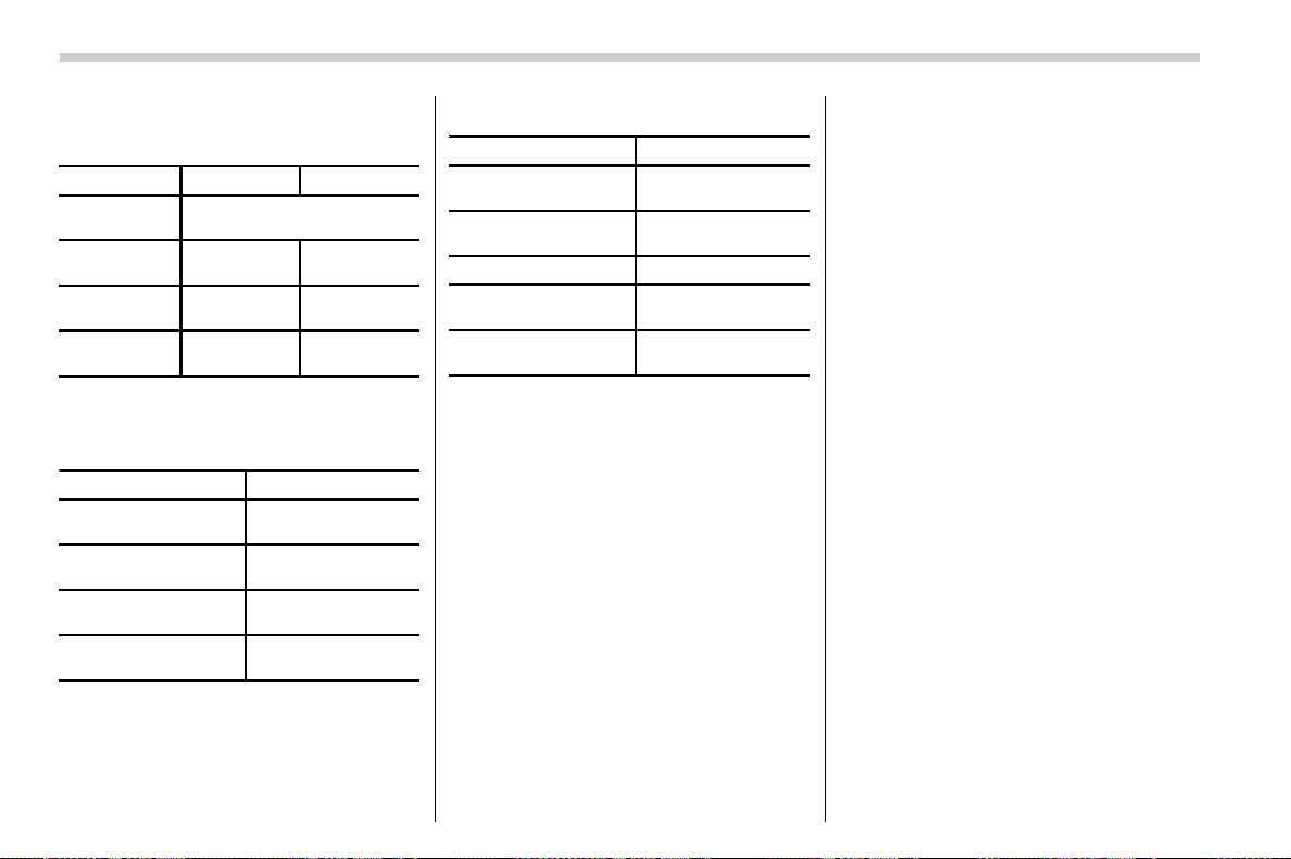
(254,1)
北米Model "A1700BE-B" EDITED: 2017/ 10/ 11
! File information
Compatible compressed files (Audio)
Item USB DISC
Compatible
file format
MP3/WMA/AAC
Folders in the
device
Maximum
512
Maximum
255
Files in the
device
Maximum
8000
Maximum
512
Files per
folder
Maximum
255
—
Corresponding sampling frequency
(Audio)
File type Frequency (kHz)
MP3 files:
MPEG 1 LAYER 3
32/44.1/48
MP3 files:
MPEG 2 LSF LAYER 3
16/22.05/24
WMA files:
Ver. 7, 8, 9 (9.1/9.2)
32/48/64/80/96/128/
160/192
AAC files:
MPEG4/AAC-LC
48/44.1/32/24/22.05/
16/12/11.025/8
Corresponding bit rates (Audio)
File type Bit rate (kbps)
MP3 files:
MPEG 1 LAYER 3
32 - 320
MP3 files:
MPEG 2 LSF LAYER 3
8 - 160
WMA files: Ver. 7, 8 CBR 48 - 192
WMA files:
Ver. 9 (9.1/9.2)
CBR 32 - 192
AAC files:
MPEG4/AAC-LC
16 - 320
(Variable Bit Rate (VBR) compatible)
. MP3 (MPEG Audio Layer 3), WMA
(Windows Media Audio) and AAC (Ad-
vanced Audio Coding) are audio compres-
sion standards.
. This system can play MP3/WMA/AAC
files on CD-R, CD-RW discs, USB mem-
ory, and Bluetooth device.
. This system can play disc recordings
compatible with ISO 9660 level 1 and level
2 and with the Romeo and Joliet file
system.
. When naming an MP3/WMA/AAC file,
add an appropriate file extension (.mp3/
.wma/.m4a).
. This system plays back files with .mp3/
.wma/.m4a file extensions as MP3/WMA/
AAC files respectively. To prevent noise
and playback errors, use the appropriate
file extension.
. This system can play only the first
session when using multi-session compa-
tible CDs.
. MP3 files are compatible with the ID3
Tag Ver. 1.0, Ver. 1.1, Ver. 2.2 and Ver. 2.3
formats. This system cannot display disc
title, track title and artist name in other
formats.
. WMA/AAC files can contain a WMA/
AAC tag that is used in the same way as an
ID3 tag. WMA/AAC tags carry information
such as track title and artist name.
. The emphasis function is available only
when playing MP3/WMA files recorded at
32, 44.1 and 48 kHz.
. This system can play back AAC files
encoded by iTunes.
. The sound quality of MP3/WMA files
generally improves with higher bit rates. In
order to achieve a reasonable level of
sound quality, discs recorded with a bit rate
of at least 128 kbps are recommended.
. The MP3/WMA player does not play
back MP3/WMA files from discs recorded
using packet write d ata transfer (UDF
format). Discs should be recorded using
“pre-mastering” software rather than pack-
etwrite software.
. M3u playlists are not compatible with
Audio/Audio set
5-10
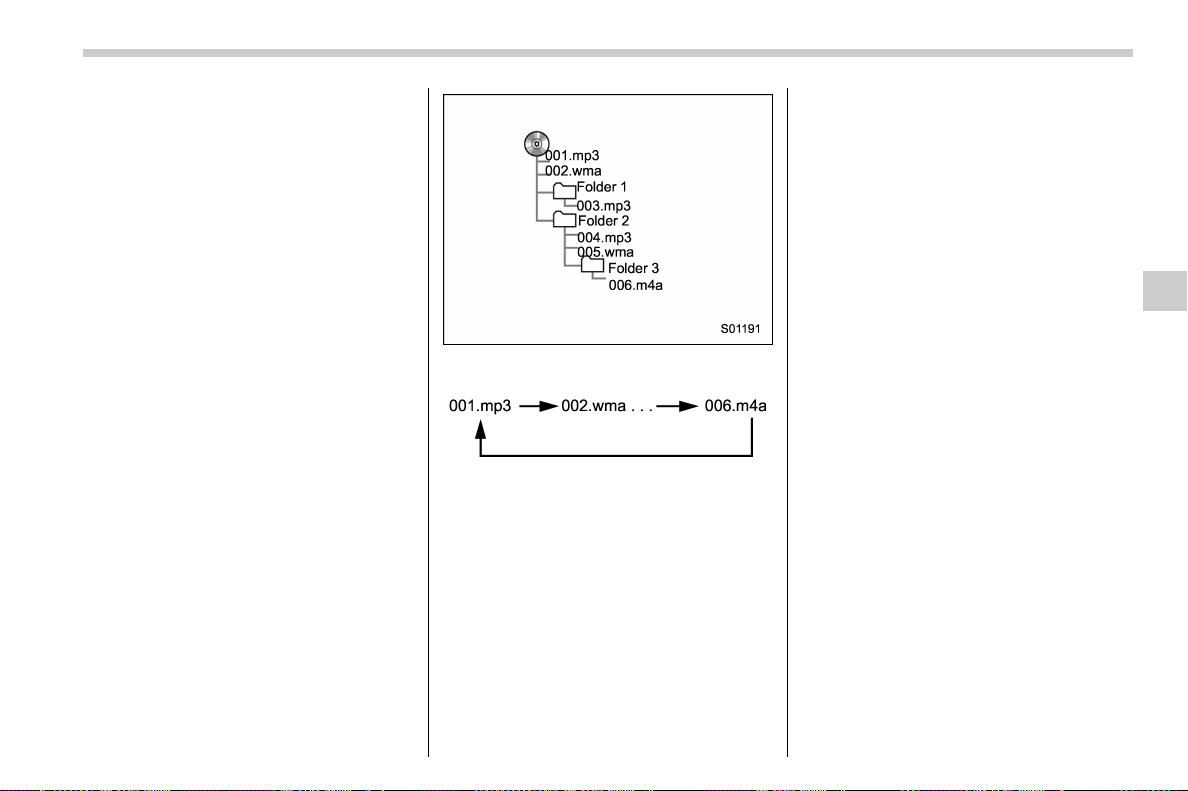
(255,1)
北米Model "A1700BE-B" EDITED: 2017/ 10/ 11
the audio device.
. MP3i (MP3 interactive) and MP3PRO
formats are not compatible with the audio
device.
. The player is compatible with VBR
(Variable Bit Rate).
. When playing back files recorded as
VBR (Variable Bit Rate) files, the play time
will not be correctly displayed if the fast
forward or reverse operations are used.
. It is not possible to check folders that do
not include MP3/WMA/AAC files.
. MP3/WMA/AAC files in folders up to 8
levels deep can be played. However, the
start of playback may be delayed when
using discs containing numerous levels of
folders. For this reason, we recommend
creating discs with no more than 2 levels of
folders.
. The play order of the compact disc with
the structure shown above is as follows:
. The order changes depending on the
personal computer and MP3/WMA/AAC
encoding software you use.
! Terms
! Packet write
. This is a general term that describes the
process of writing data on-demand to CD-
R, etc., in the same way that data is written
to floppy or hard discs.
! ID3 tag
. This is a method of embedding track-
related information in an MP3 file. This
embedded information can include the
track number, track title, the artist’s name,
the album title, the music genre, the year of
production, comments, cover art and other
data. The contents can be freely edited
using software with ID3 tag editing func-
tions. Although the tags are restricted to a
number of characters, the information can
be viewed when the track is played back.
! WMA tag
. WMA files can contain a WMA tag that
is used in the same way as an ID3 tag.
WMA tags carry information such as track
title and artist name.
! ISO 9660 format
. This is the international standard for the
formatting of CD-ROM folders and files.
For the ISO 9660 format, there are 2 levels
of regulations.
. Level 1: The file name is in 8.3 format (8
character file names, with a 3 character file
extension. File names must be composed
of one-byte capital letters and numbers.
The “_” symbol may also be included.)
– CONTINUED –
Audio/Audio set
5-11
5

(256,1)
北米Model "A1700BE-B" EDITED: 2017/ 10/ 11
. Level 2: The file name can have up to
31 characters (including the separation
mark “.” and file extension). Each folder
must contain fewer than 8 hierarchies.
! MP3
. MP3 is an audio compression standard
determined by a working group (MPEG) of
the ISO (International Standard Organiza-
tion). MP3 c ompresses audio data to
about 1/10 the size of that on conventional
discs.
! WMA
. WMA (Windows Media Audio) is an
audio compression format developed by
Microsoft
®
. It compresses files into a size
smaller than that of MP3 files. The decod-
ing formats for WMA files are Ver. 7, 8 and
9.
. This product is protected by certain
intellectual property rights of Microsoft
Corporation and third parties. Use or
distribution of such technology outside of
this product is prohibited without a license
from Microsoft or an authorized Microsoft
subsidiary and third parties.
! AAC
. AAC is short for Advanc ed Audio
Coding and refers to an audio compres-
sion technology standard used with
MPEG2 and MPEG4.
Audio/Audio set
5-12
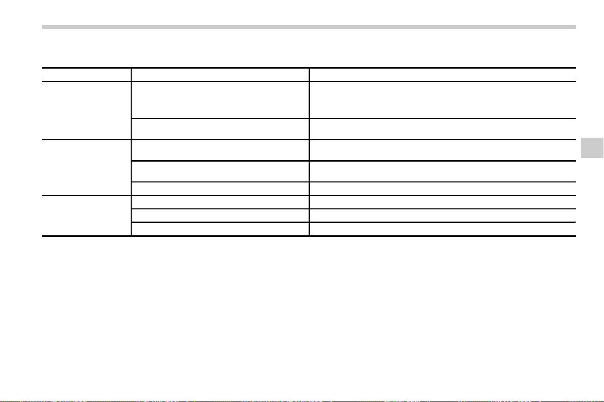
(257,1)
北米Model "A1700BE-B" EDITED: 2017/ 10/ 11
! Error messages
Mode Message Explanation
CD
“Disc read error.”
. This indicates that no MP3/WMA/AAC files are included in the disc.
. This indicates that the disc is dirty, damaged, or it was inserted upside
down. Clean the disc or insert it correctly. It indicates a disc which is not
playable is inserted.
“Please eject disc.”
There is a trouble inside the system.
Eject the disc.
USB
“Media not connected. Press AUDIO/TUNE knob
to exit.”
This indicates a problem in the USB memory or its connection. Refer to
“
Connecting and disconnecting a USB memory/portable device” F5-16.
“No audio file.”
This indicates that no MP3/WMA/AAC files are included in the USB
memory.
“Unplayable file” This indicates that the accessed file cannot play back.
iPod
“Media not connected” This indicates that a USB device/iPod is not connected to the system.
“No audio file” This indicates that there is no audio file in the connected iPod.
“Unplayable file”
This indicates that the accessed file cannot play back.
NOTE
If the malfunction is not rectified: Take your vehicle to your SUBARU dealer.
– CONTINUED –
Audio/Audio set
5-13
5
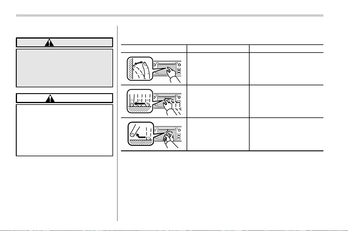
(258,1)
北米Model "A1700BE-B" EDITED: 2017/ 10/ 11
& Basic information before use
WARNING
When the vehicle is stopped with the
engine running, always apply the
parking brake for safety. Failure to
do so may result in loss of control of
your vehicle and cause an accident
or serious injury.
CAUTION
. To prevent damaging the screen,
touch the screen keys with your
finger lightly.
. Wipe off fingerp rints using a
glass cleaning cloth. Do not use
chemical cleaners to clean the
screen, as they may damage the
touch screen.
! Touch screen gestures
Operations are performed by touching the touch screen directly with your finger.
Operation method Outline Main use
Touch
Quickly touch and release
once.
Changing and selecting various
settings
Drag*
Touch the screen with your
finger, and move the screen
to the desired position.
Scrolling the lists
Flick*
Quickly move the screen by
flicking with your finger.
Scrolling the main screen page
*: The above operations may not be performed on all screens.
NOTE
There may be a delayed response to flick operation that are performed at high
altitudes.
Audio/Audio set
5-14

(259,1)
北米Model "A1700BE-B" EDITED: 2017/ 10/ 11
! Touch screen operation
This system is operated mainly by the keys
on the screen.
When a screen key is touched, a beep
sounds. You can set the beep sound.
Refer to “Unit settings” F5-18.
NOTE
. If the system does not respond to
touching a scre en key, mov e your
finger away from the screen and touch
it again.
. Grayed-out screen keys cannot be
operated.
. The displayed image may become
darker and moving images may be
slightly distorted when the screen is
cold.
. In extremely cold conditions, the
screen may not be displayed correctly.
Also, the screen keys may be less
responsive than usual when pressed.
. When you look at the screen through
polarized material such as polarized
sunglasses, the screen may be dark
and difficult to see. If so, look at the
screen from different angles, adjust the
screen settings or take off your sun-
glasses. Refer to “Unit settings” F5-18.
! Entering letters and numbers/list
screen operation
! Entering letters and numbers
When entering the Bluetooth device name
or PIN-code, or the phone number, letters
and numbers can be entered via the
screen.
Enter letters (example: In-Car-Device
setting)
No. Function
&
1
Enter the desired characters (alpha-
bet key mode).
&
2
Switch to the screen for characters.
&
3
Enter a space.
&
4
Confirm the characters/numbers en-
tered into the window.
No. Function
&
5
Delete a character/number entered
into the window.
! List screen
Multimedia playlists (example: iPod play-
list)
No. Function
&
1
Select a category that wants to play
back.
&
2
Return to the playback display of
each mode.
&
3
Select to skip to the next or previous
page.
– CONTINUED –
Audio/Audio set
5-15
5
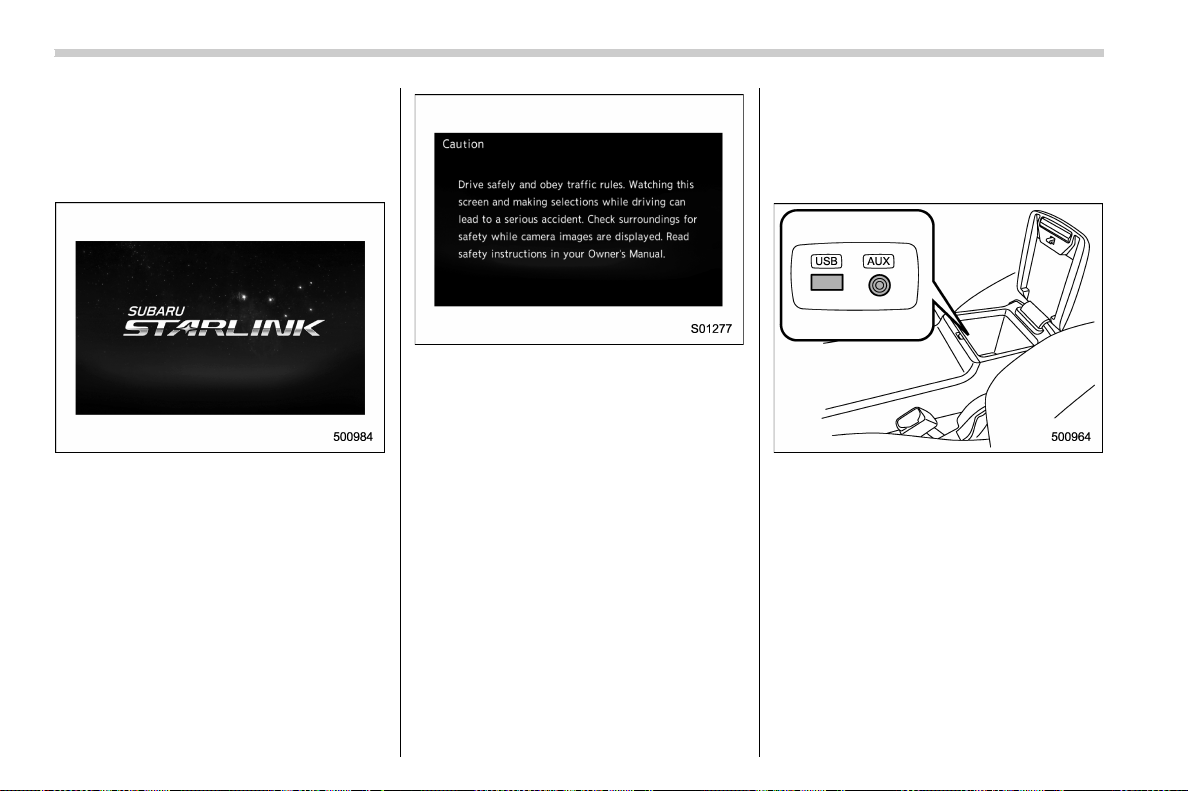
(260,1)
北米Model "A1700BE-B" EDITED: 2017/ 10/ 11
! Initial screen
When the ignition switch is in the “ACC” or
“ON” position, the initial screen will be
displayed and the sys tem will begin
operating.
. When using the SUBARU STARLINK
function (if equipped), the display screen
may be different from the screen above.
. After a few seconds, the caution screen
will be displayed.
. After about 5 seconds, the cautio n
screen automatically switches to the next
screen.
! Connecting and disconnecting a
USB memory/portable device
The USB port and the AUX jack are
located as shown in the following illustra-
tion.
NOTE
. This unit does not support commer-
cially available USB hubs.
. Turn on the power of the device
when it is not turned on.
. This device has a USB port for USB
memory/portable device.
. For compatible USB memory de-
vices, refer to “USB memory device”
F5-9.
. For compatible iPod models, refer to
“iPod” F5-9.
. Even if a USB hub is used to connect
more than two USB devices, only the
Audio/Audio set
5-16

(261,1)
北米Model "A1700BE-B" EDITED: 2017/ 10/ 11
first two connected devices will be
recognized.
& Basic operation
This section describes some of the basic
features of the audio/visual system. Some
information may not pertain to your sys-
tem.
Your audio/visual system works when the
ignition switch is turned to the “ACC” or
“ON” position.
CAUTION
To prevent the battery from being
discharged, do not leave the audio/
visual system on longer than neces-
sary when the engine is not running.
NOTE
Some functions can also be operated
by using the voice command system.
For details, refer to “Voice command
system” F5-79.
! Turning the system on and off
Press the power/VOLUME knob to turn the
audio/visual system on and off. When the
system turns on, the mode that was in use
the last time the system was turned off will
be displayed. Press and hold the knob to
turn the display off.
Turn this knob to adjust the volume.
! Selecting an audio source
1. Press the AUDIO/TUNE knob.
2. Select the desired source.
Example: Source select screen
– CONTINUED –
Audio/Audio set
5-17
5
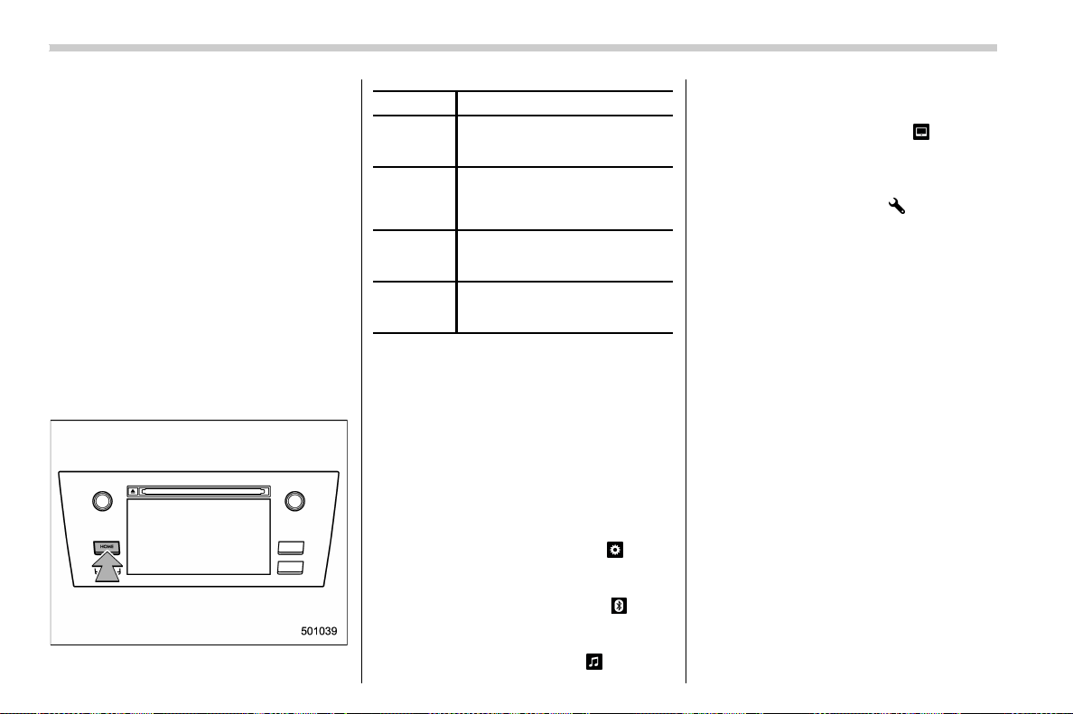
(262,1)
北米Model "A1700BE-B" EDITED: 2017/ 10/ 11
NOTE
. If the audio control screen appears,
select the “Source” key on the audio
screen or press the AUDIO/TUNE knob
again.
. When you push the AUDIO/TUNE
knob while any screen other than the
audio control screen is displayed, the
display will return to the audio control
screen.
. When the AUDIO/TUNE knob is
pushed and held, the graphic equalizer
screen will be displayed. Refer to
““Graphic Equalizer”” F5-22.
! Selecting a function menu
Press the HOME button to display home
screen.
Item Function
AUDIO
Select to display the main screen
of the audio source that was
selected previously.
PHONE
Select to display the hands-free
function using your cell phone.
Refer to “
Hands-free phone sys-
tem” F5-69.
APPS
Select to display the functions
linked with a smartphone. Refer
to “
SUBARU STARLINK” F5-25.
SETTINGS
Select to display the functions for
performing various settings. Re-
fer to “
Unit settings” F5-18.
& Unit settings
Sound quality adjustment, screen adjust-
ment, and information of the audio unit are
displayed.
1. Press the HOME button on the audio
panel.
2. Touch the “SETTINGS” key.
3. Select the items to be set.
Available setting:
. General settings: Select the
tab to
check the system software update infor-
mation. Refer to “General settings” F5-19.
. Bluetooth settings: Select the
tab to
set the Bluetooth settings. Refer to “Blue-
tooth settings” F5-19.
. Sound settings: Select the
tab to set
the sound quality settings. Refer to “Sound
settings” F5-19.
. Display settings: Select the
tab to set
the screen settings. Refer to “Display
settings” F5-24.
. SUBARU STARLINK settings (if
equipped): Select to the
tab set the
SUBARU STARLINK settings. Refer to
“SUBARU STARLINK settings” F5-25.
Audio/Audio set
5-18
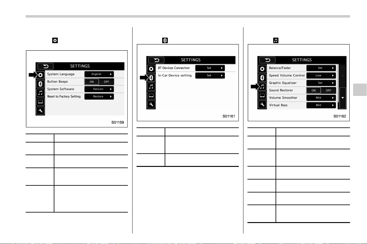
(263,1)
北米Model "A1700BE-B" EDITED: 2017/ 10/ 11
! General settings
Touch the
tab for the audio unit basic
settings.
Item Function
System
Language
Select to change the language.
Button
Beeps
Select to set the sound beeps on/
off.
System
Software
Select to update software ver-
sions. This menu is not used in
usual operation.
Reset to
Factory
Setting
Select to reset the device to
factory settings. This menu is not
used in usual operation.
After resetting to factory settings,
turn ignition off and on again.
! Bluetooth settings
Touch the
tab to set Bluetooth.
Item Function
BT De-
vices Con-
nection
Select to pair/connect the Blue-
tooth devices.
In-Car-De-
vice setting
Select to enter the Bluetooth
device name or PIN-code.
For details, refer to “Bluetooth
®
settings”
F5-64.
! Sound settings
Touch the
tab to set the sound quality.
Item Function
Balance/
Fader
Select to adjust speaker volume
balance (right/left and front/rear).
Speed Vo-
lume Con-
trol
Select to adjust speaker volume
coupled to vehicle speed.
Graphic
Equalizer
Select to adjust sound quality in
each frequency band.
Sound Re-
storer
Select to add high-pitched tone
to the compressed audio file.
Volume
Smoother
Select to adjust volume differ-
ence between audio sources.
Virtual
Bass
Select to add harmonic tone so
that low-pitched tone is
strengthened.
– CONTINUED –
Audio/Audio set
5-19
5
(264,1)
北米Model "A1700BE-B" EDITED: 2017/ 10/ 11
Item Function
Vocal Im-
age Con-
trol
Select to pick-up vocal sound
signal from the sound data, and
adjust it to right/left or front/rear.
Refer to the following table for the adjustment range of each audio setting item and default
value.
Item Step Default
Balance/
Fader
Volume
Balance
Control
Balance L9-R9 0 (Center)
Fader F9-R9 0 (Center)
Vocal
Image
Control
Balance L9-R9 R3
Fader F9-R9 0 (Center)
Speed Volume Control OFF, Low, High Low
Graphic Equalizer −6-+6 0 (Flat)
Sound Restorer ON, OFF ON
Volume Smoother OFF, Low, Mid, High Mid
Virtual Bass OFF, Low, Mid, High
Mid
Audio/Audio set
5-20
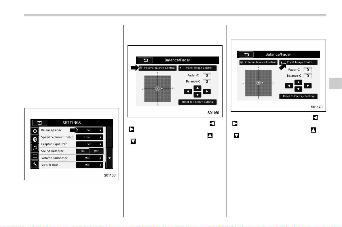
(265,1)
北米Model "A1700BE-B" EDITED: 2017/ 10/ 11
! “Balance/Fader”
A good balance of the left and right stereo
channels and of the front and rear sound
levels is important for good quality audio
program listening.
Keep in mind that when listening to a
stereo recording or broadcast, changing
the right/left balance will increase the
volume of 1 group of sounds while
decreasing the volume of another.
Touch the “Set” key of the “Balance/Fader”
key. The “Balance/Fader” scree n will
appear.
. Volume Balance setting
1. Select the “Volume Balance Control”
key.
2. Adjust the balance by pressing “ ” or
“
” key.
3. Adjust the fader by pressing “
” or
“
” key.
. Vocal image setting
1. Select the “Vocal Image Control” key.
2. Adjust the balance by pressing “ ” or
“
” key.
3. Adjust the fader by pressing “
” or
“
” key.
– CONTINUED –
Audio/Audio set
5-21
5
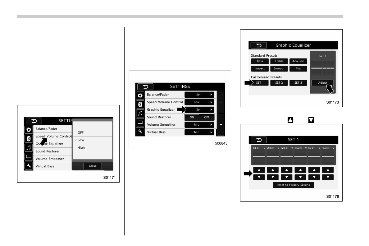
(266,1)
北米Model "A1700BE-B" EDITED: 2017/ 10/ 11
! “Speed Volume Control”
The system adjusts to the optimum volume
and t one quality according to vehicle
speed to compensate for increased vehi-
cle noise.
1. Touch the right side key of the “Speed
Volume Control” key.
2. Select the desired item. The “ High” key
comes to have a bigger effect. When the
“OFF” key is selected, speed volume
control function is cancelled.
! “Graphic Equalizer”
You can adjus t the sound quality by
increasing/decreasing the gain for each
frequency range.
1. Touch the “Set” key of the “Graphic
Equalizer” key.
2. In this mode, 6 preset equalizer pat-
terns (the “Bass”, “Treble”, “Acoustic”,
“Impact”, “Smooth” and “Flat” key) and 3
customized patterns (the “SET 1” - “SET 3”
key) are available.
3. When customizing the equalizer pat-
tern, touch among “SET 1”, “SET 2” or
“SET 3” and then touch the “Adjust” key.
4. Adjust the level of each frequency
band by touching “
” or “ ” key.
Audio/Audio set
5-22
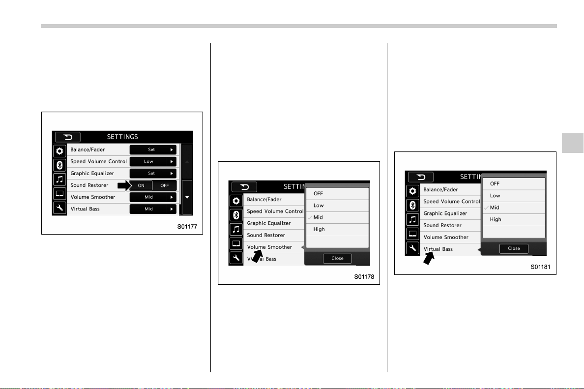
(267,1)
北米Model "A1700BE-B" EDITED: 2017/ 10/ 11
! “Sound Restorer”
You can play compressed audio data with
a sound quality that is close to the original
sound.
Select the “ON” or “OFF” key by the right
side key of the “Sound Restorer” key.
! “Volume Smoother”
This function reduces the difference in
volume among the sound sources to be
played.
1. Touch the right side key of the “Volume
Smoother” key.
2. Select the “OFF”, “Low”, “Mid” or “High”
key. The “High” key comes to have a
bigger effect. When the “OFF” key is
selected, the volume smoother function is
cancelled.
! “Virtual Bass”
This function enables you to adjust the
bass tone.
1. Touch the right side key of the “Virtual
Bass” key.
2. Select the “OFF”, “Low”, “Mid” or “High”
key. The “High” key comes to have a
bigger effect. When the “OFF” key is
selected, the virtual bass func tion is
cancelled.
! “Vocal Image Control ”
Refer to ““Balance/Fader”” F5-21.
– CONTINUED –
Audio/Audio set
5-23
5
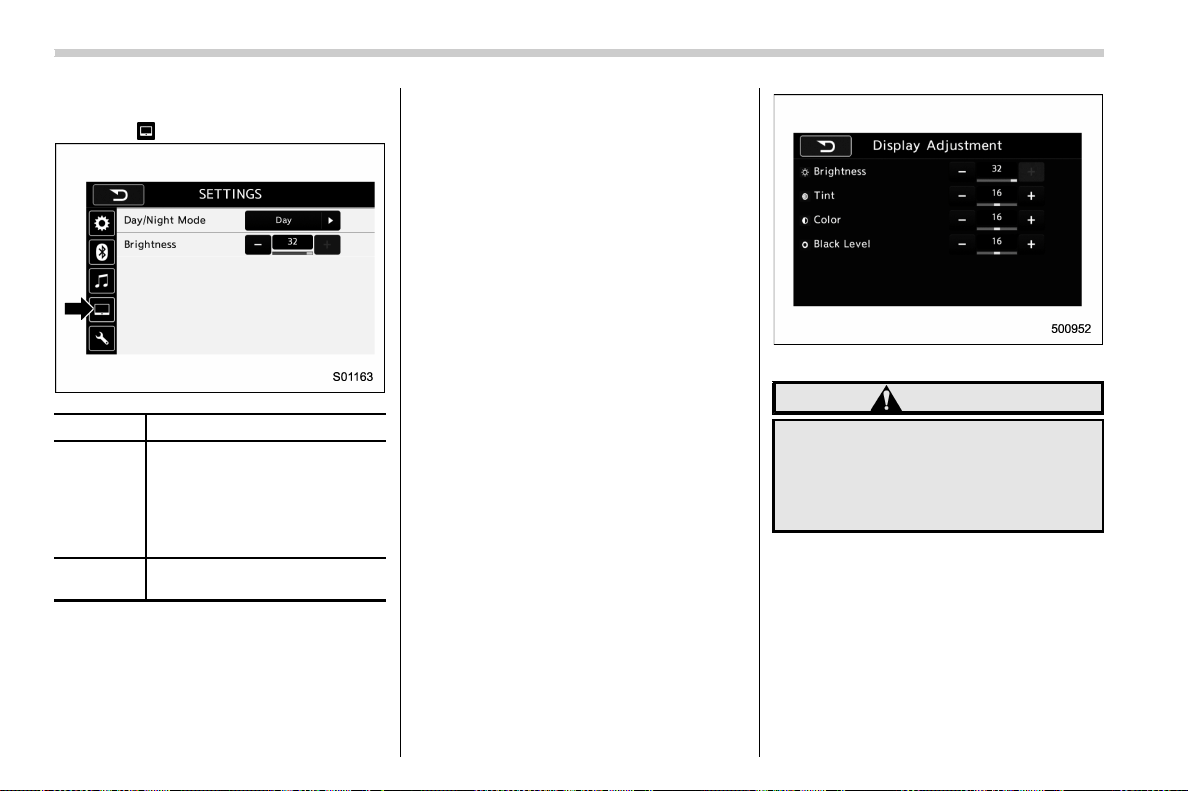
(268,1)
北米Model "A1700BE-B" EDITED: 2017/ 10/ 11
! Display settings
Touch the
tab to set display.
Item Function
Day/Night
Mode
The “Auto”, “Day” or “Night” key
can be selected on the pop-up
screen.
When the “Auto” key is selected,
the screen changes to day or
night mode depending on the
position of the headlight switch.
Brightness
Touch “+” or “−” to adjust the
brightness.
NOTE
. When the screen is viewed through
polarized sunglasses, a rainbow pat-
tern may appear on the screen due to
optical characteristics of the screen. If
this is disruptive, please operate the
screen without polarized sunglasses.
. If the screen is set to “Day” mode
with the headlight switch turned on,
this condition is memorized even with
the engine turned off.
! How to adjust the rear view image
In the camera display, the brightness, tint,
color and black level of the screen can be
adjusted.
1. Depress the brake pedal fully and stop
the vehicle.
2. While the vehicle is stopped, set the
shift lever (MT models) or select lever
(CVT models) in the “R” position, and then
touch the display.
3. Touch the “Display Adjustment” key.
4. Touch the items to adjust the rear
camera screen.
Camera display
WARNING
When adjusting camera display
screen, make sure to depress the
brake pedal fully to avoid the vehicle
from moving. Failure to do so may
lead to a serious accident.
NOTE
The camera display can be accessed
when the rear camera monitor is dis-
played.
Audio/Audio set
5-24
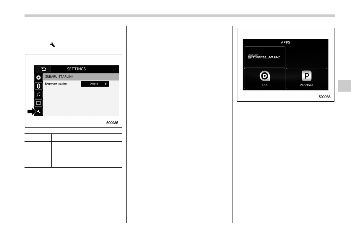
(269,1)
北米Model "A1700BE-B" EDITED: 2017/ 10/ 11
! SUBARU STARLINK settings (if
equipped)
Touch the
tab to change the SUBARU
STARLINK settings.
Item Function
Browser
cache
Select to initialize cache files that
the browser stores. If the con-
firmation screen appears and the
“OK” key is selected, the cache
files will be deleted.
& SUBARU STARLINK (if
equipped)
The SUBARU STARLINK function allows
the system to link with a smartphone using
Bluetooth.
! How to use SUBARU STARLINK
1. Connect to the audio system. Use a
USB port for an iPhone or iPod touch and
Bluetooth for Android devices.
. For details about connecting an
iPhone/iPod touch: Refer to “Connect-
ing and disconnecting a USB memory/
portable device” F5-16.
. For details about registering or con-
necting an Android device: Refer to
“Registering/connecting Bluetooth
®
device” F5-64.
2. Press the HOME button, and then
touch the “APPS” key, or press the APPS
button on the audio panel. The APPS
screen is displayed.
3. Touch the “SUBARU STARLINK” key
on the APPS screen. The disclaimer
screen or the error screen is displayed.
4. Touch the “Check” key on the disclai-
mer screen and then the APPS main
screen will appear. If you touch the
“Cancel” key, the disclaimer screen dis-
appears and the previous screen will be
displayed again.
NOTE
. The SUBARU STARLINK connection
error screen will be displayed due to
one of the following possible reasons.
– Your smartphone and the system
has not been connected via USB (for
iPhone) or Bluetooth (for Android).
– SUBARU STARLINK APPS has
not been activated.
– CONTINUED –
Audio/Audio set
5-25
5
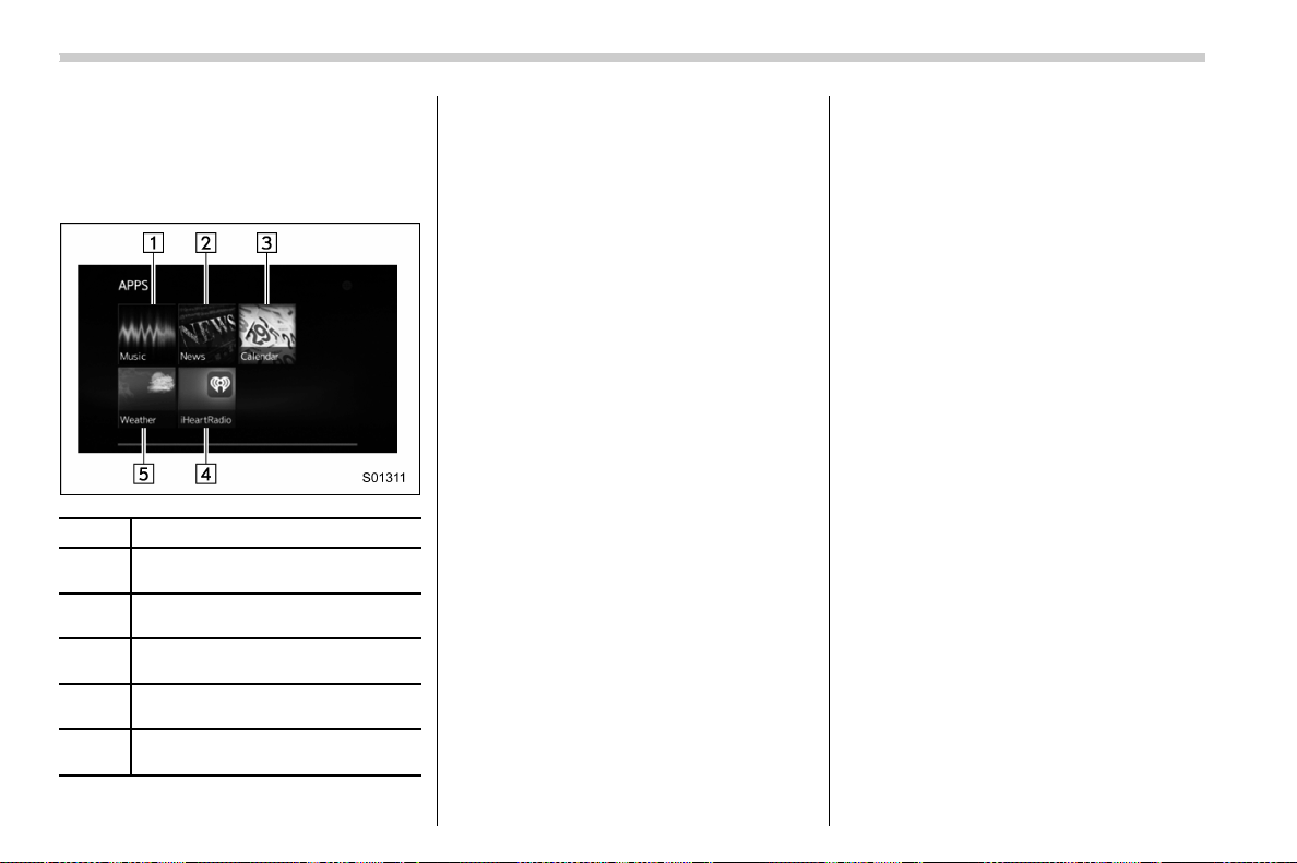
(270,1)
北米Model "A1700BE-B" EDITED: 2017/ 10/ 11
. You can also switch to aha o r
Pandora (if equipped) from the APPS
screen.
! APPS main screen
No. Function
&
1
Select to go to the Music APPS
screen.
&
2
Select to go to the News APPS
screen.
&
3
Select to go to the Calender APPS
screen.
&
4
Select to go to the iHeartRadio
APPS screen.
&
5
Select to go to the Weather APPS
screen.
NOTE
. The error screen will be displayed
while using SUBARU STARLINK due to
one of the following possible reasons.
– When your smartphone has no
service or the Bluetooth communi-
cation is not possible.
– When your smartphone is turned
off.
– When the SUBARU STARLINK
APPS is quit.
– When connection to the SUBARU
STARLINK server is not possible.
– When a problem occurs other
than a server error.
. When using the SUBARU STARLINK
function, a disclaimer screen will be
displayed. Be sure to fully read the
contents before using the function.
. Supported devices
– iPhone: iPhone 4/iPhone 4s/
iPhone 5 (iOS Ver. 5.1 or later)/
iPhone 5c/iPhone 5s
– Android: (OS Ver. 4.0 or later)
Audio/Audio set
5-26
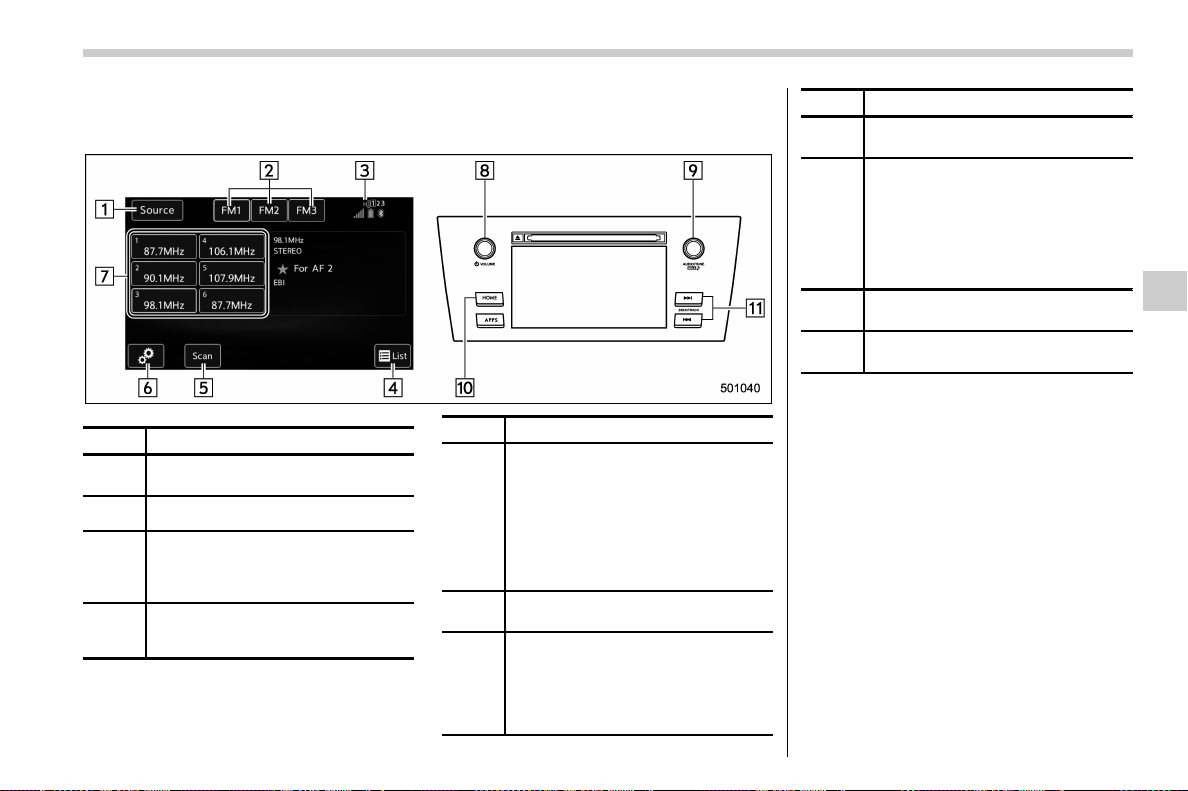
(271,1)
北米Model "A1700BE-B" EDITED: 2017/ 10/ 11
& AM/FM radio
! Control screen and audio panel
No. Function
&
1
Select to display the audio source
selection screen.
&
2
Select to change the band.
&
3
The HD Radio indicator on the top
right of the screen changes accord-
ing to the reception condition of HD
Radio (if equipped).
&
4
Select to display a station list (if
equipped). Refer to “
Selecting a sta-
tion from the list” F5-28.
No. Function
&
5
Select to scan radio channels.
This function enables searching for
receivable stations automatically,
and tunes in to a frequency for 5
seconds if a station is found. When
the 5-second period has elapsed, the
system searches for the next recei-
vable station again, and tunes in to
the frequency for 5 seconds.
&
6
Select to open the “Option” screen.
Refer to “
Radio settings” F5-29.
&
7
When you touch a key, the system
tunes to the stored frequency.
When you touch and hold a key, the
system stores the frequency to the
selected preset channel. Refer to
“
Presetting a station” F5-28.
No. Function
&
8
Turn to adjust volume.
Press to turn the audio system on/off.
&
9
Turn to step up/down frequencies.
Turn to move up/down the list. Also,
the knob can be used to enter
selections on the list screens by
pressing.
Press to select an audio mode. For
details, refer to “
Selecting an audio
source” F5-17.
&
10
Press to display the sound setting
screen. Refer to “
Unit settings” F5-18.
&
11
Press to seek for a station/channel.
Press and hold for continuous seek.
NOTE
. Although FM is normally static free,
reception can be affected by the sur-
rounding area, atmospheric condi-
tions, station strength and transmitter
distance. Buildings or other obstruc-
tions may c ause momentary static,
flutter or station interference. If recep-
tion c ontinues to be unsatisfactory,
switch to a stronger station.
. The radio automatically changes to
stereo reception when a stereo broad-
cast is received.
– CONTINUED –
Audio/Audio set
5-27
5

(272,1)
北米Model "A1700BE-B" EDITED: 2017/ 10/ 11
. The radio automatically blends to an
HD Radio signal (if equipped) in AM or
FM where available.
! How to change the source
Select the “AM” or “FM” key on the source
select screen. Refer to “Selecting an audio
source” F5-17.
! Presetting a station
In total 18 stations can be set for the FM
band (6 each for FM1, FM2 and FM3) and
12 stations can be set for the AM band (6
each for AM1 and AM2).
1. Tune in the desired station.
2. If you touch and hold a key, the system
stores the frequency to the selected preset
channel.
! Selecting a station from the list (if
equipped)
A station list can be displayed.
1. Touch the
tab.
2. Touch the tab and the station list will
appear.
3. Select the desired station.
! Update the station list
Touch the “Update Station List” key on the
station list screen and the following screen
will be displayed.
Item Function
OK
Select to execute the manual
update.
Cancel
Select to cancel the manual
update.
NOTE
. The audio system sound is muted
during refresh operation.
. In some situations, it may take some
time to update the station list.
! Bookmark the list
You can store and call up the received data
(images, song titles, artist names, etc.).
The stored data is displayed as a list.
1. Touch the
tab on the station list
screen and the following screen will be
Audio/Audio set
5-28
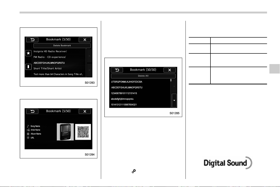
(273,1)
北米Model "A1700BE-B" EDITED: 2017/ 10/ 11
displayed.
2. Select an item from the bookmark list,
the following image will be displayed.
3. When you call up bookmark informa-
tion, a QR code converted from the book-
mark information will be displayed on the
screen. You can access a URL by reading
the QR code using a smartphone, etc.
! Delete bookmark from the list
1. Touch the “Delete Bookmark” key on
the station list screen and the following
screen will be displayed.
2. If you select an item from the bookmark
list, the item will be deleted from the
bookmark list.
3. Touch the “Delete All ” key. If the
confirmation screen appears and the
“OK” key is selected, all bookmark items
in the list will be deleted.
! Radio settings
You can perform various radio settings.
1. Touch the
tab.
2. Select the desire d item from the
following table.
Item Function
HD (if
equipped)
Select to turn HD radio on/off.
PTY Select
(if
equipped)
Select to set the PTY group.
Auto Store
Select to detect 6 radio stations
with strong frequencies automa-
tically and to store them in the
order of frequency.
! About HD Radio
TM
technology (if
equipped)
HD Radio
TM
Technol ogy is the digital
evolution of analog AM/FM radio. Your
radio product has a special receiver which
allows it to receive digital broadcasts
(where available) in addition to the analog
broadcasts it already receives. Digital
broadcasts have better sound quality than
analog broadcasts as digital broadcasts
provide free, crystal clear audio with no
static or distortion. For more information,
and a guide to available radio stations and
programming, refer to www.hdradio.com.
– CONTINUED –
Audio/Audio set
5-29
5
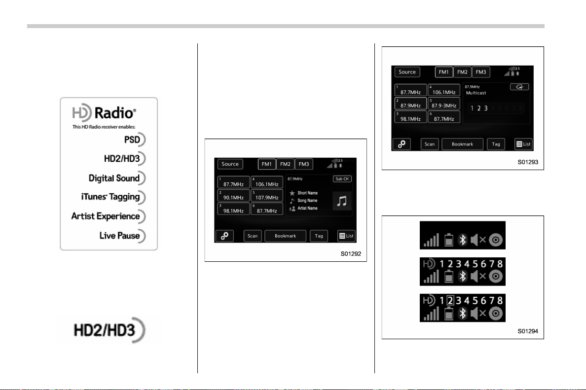
(274,1)
北米Model "A1700BE-B" EDITED: 2017/ 10/ 11
AM and FM broadcast sound quality is now
crystal clear, with AM sound quality that
virtually matches FM quality of the past,
and FM broadcasts that have near CD-
level sound quality.
HD Radio Technology manufactured un-
der license from iBiquity Digital Corpora-
tion. Foreign Patents. HD Radio
TM
and the
HD, HD Radio, and “Arc” logos are
proprietary trademarks of iBiquity Digital
Corp.
FM stations can provide additional digital-
only audio programming on HD2/HD3
Channels.
! Available HD Radio
TM
technology (if
equipped)
! Multicast
On the FM radio frequency most digital
stations have “multiple” or supplemental
programs on one FM station.
1. Touch the “Sub CH” key on the control
screen and the following screen will be
displayed.
2. The indication that shows whether the
current broadcast is digital or analog is
displayed on the top right of the control
screen.
3. Select the desired channel.
Turning the AUDIO/TUNE knob can also
Audio/Audio set
5-30
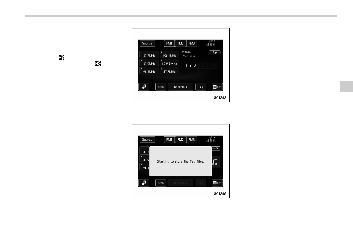
(275,1)
北米Model "A1700BE-B" EDITED: 2017/ 10/ 11
select the desired multicast channel.
NOTE
. HD Radio
TM
stations can be preset.
. An orange
will be displayed on the
screen when in digital. The
will first
appear in a gray color indicating the
station is indeed (an analog and) a
digital station. Once the digital signal
is acquired, the logo will change to a
bright orange color.
. The song title and artist name will
appear on the screen when available by
the radio station. The radio station can
send album pictures when available.
. As a user works through the analog
radio stations, (where applicable) the
radio receiver will automatically tune
from an analog signal to a digital signal
within 5 seconds.
! Preserving a music information
Tag information in the music broadcasting
is preserved in the system and transmits to
an iPod.
1. Touch the “Tag” key in the control
screen while receiving HD Radio, the tag
setting screen will be displayed.
2. Connect an iPod. Refer to “Connecting
and disconnecting a USB memory/porta-
ble device” F5-16.
. Turn on the power of the iPod if it is
not turned on.
. Onc e an iPod is co nn ec ted, the
music tag moves from the radio into
the iPod.
. When the i Pod is connected to
iTunes, the tagged information of the
songs which were tagged while listen-
ing to the radio can be viewed. Then a
user may decide to purchase the song
or CD/Album which had been listened
to on their radio.
– CONTINUED –
Audio/Audio set
5-31
5
(276,1)
北米Model "A1700BE-B" EDITED: 2017/ 10/ 11
In addition, the following messages appear.
Display Message Contents
“Tag storage full”
If there is not enough memory in the digital
audio
“Already Stored”
If the same information is stored in the digital
audio
“Storing Failed” If the store process in the digital audio failed
“iPod full Tags cannot be stored” If there is not enough memory in the iPod
“Starting to transfer the Tag files.”
If the system starts to transmit music informa-
tion to an iPod
“Transferring Failed”
If the transmitting process of music information
to an iPod failed
“X Tag(s) Sent” (X = number of transmitted
information) will be displayed.
If the transmitting process of music information
to an iPod is successful
NOTE
. The tag information can not be
preserved while scanning or caching
the radio station.
. If tagging the music information
fails, “Saving the HD Radio tag was
unsuccessful. (Saving the HD Radio tag
was unsuccessful.)” will be displayed
on the screen. If this occurs, tag the
information again.
. Program Service Data: Presents song
name, artist, station IDs, and other rele-
vant data streams.
. iTunes Tagging provides you the op-
portunity to discover a wide range of
content and the means to “tag” that content
for later review and purchase from the
iTunes Store. Also refer to th e Apple
Automotive specifications for implement-
ing iTunes Tagging.
Audio/Audio set
5-32

(277,1)
北米Model "A1700BE-B" EDITED: 2017/ 10/ 11
. Visual information related to content
being played on your HD Radio receiver,
such as Album Art, historical photographs,
still art from live broadcasts, among other
related content.
– CONTINUED –
Audio/Audio set
5-33
5

(278,1)
北米Model "A1700BE-B" EDITED: 2017/ 10/ 11
! Troubleshooting guide
Experience Cause Action
Mismatch of time alignment - a user may hear a
short period of programming replayed or an
echo, stutter or skip.
The radio stations analog and digital volume is
not properly aligned or the station is in ballgame
mode.
None, radio broadcast issue. A user can contact the
radio station.
Sound fades, blending in and out.
Radio is shifting between analog and digital
audio.
Reception issue. May clear-up as the vehicle
continues to be driven. Turning the indicator of the
HD Radio
TM
off will change the radio mode to
analog audio.
Audio mute condition when an HD2/HD3
multicast channel had been playing.
The radio does not have access to digital signals
at the moment.
This is normal behavior, wait until the digital signal
returns. If out of the coverage area, seek a new
station.
Audio mute delay when selecting an HD2/HD3
multicast channel preset.
The digital multicast content is not available until
HD Radio
TM
broadcast can be decoded and
make the audio available. This takes up to 7
seconds.
This is normal behavior, wait for the audio to
become available.
Text information does not match the present
song audio.
Data service issue by the radio broadcaster.
Broadcaster should be notified. Complete the form;
www.ibiquity.com/automotive/report_radio
_station_experiences.
No text information shown for the present
selected frequency.
Data service issue by the radio broadcaster.
Broadcaster should be notified. Complete the form;
www.ibiquity.com/automotive/report_radio
_station_experiences.
The “Acquiring” caution message appears
when the system attempts to acquire digital
transmission.
When acquiring digital data while receiving a
digital broadcast and SPS station.
. When the reception in digital of the SPS station
is confirmed.
. When the system determined that the SPS
station could not be received.
. When the SPS broadcast is ended (stopped) by
the radio station while receiving SPS.
Audio/Audio set
5-34

(279,1)
北米Model "A1700BE-B" EDITED: 2017/ 10/ 11
Experience Cause Action
The “HD Channel is unavailable” caution
message appears when digital reception is not
possible.
. When the system determined that the SPS
station could not be received while receiving
a digital broadcast and SPS station.
. When the SPS broadcast is ended
(stopped) by the radio station while receiv-
ing SPS.
. When the status is changed to acquiring digital
data because the reception condition of SPS
station has improved.
. When the received station is changed.
– CONTINUED –
Audio/Audio set
5-35
5
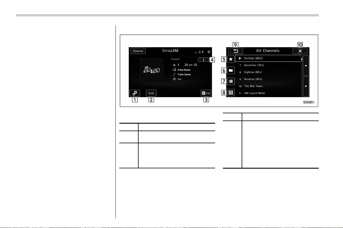
(280,1)
北米Model "A1700BE-B" EDITED: 2017/ 10/ 11
& SiriusXM Satellite Radio (if
equipped)
! SiriusXM Data Service
Data service information, which is com-
prised of traffic information and weather
information, can be receiv ed via the
SiriusXM Radio.
To receive the data service information in
the vehicle, a subscription to the SiriusXM
Satellite Radio service is necessary.
Content set to use the SiriusXM data
service is reset when personal information
is initialized.
! Control screen and audio panel
Control screen
No. Function
&
1
Perform the SXM setting. See below.
Refer to “
SXM setting” F5-41.
&
2
Search for a channel which the
direction of higher frequency from
current frequency. Reproduce the
channel that can receive by 5 sec-
onds.
No. Function
&
3
A list is displayed. There are three
types of lists (“Presets”, “Categories”
or “All Channels”) available.
. “Presets”: Preset channels are
displayed in a list.
. “Categories”: The channels of
the selected category are dis-
played in a list.
. “All Channels”: All selectable
channels are displayed in a list.
Audio/Audio set
5-36
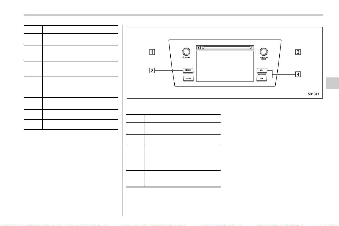
(281,1)
北米Model "A1700BE-B" EDITED: 2017/ 10/ 11
No. Function
&
4
Display the contents information of a
channel receiving.
&
5
Presets list (30 channels max.) is
displayed. Refer to “
Presetting a
channel” F5-39.
&
6
Categories list is displayed. Refer to
“
Selecting a channel from the list” F5-
40.
&
7
All channels list is displayed.
The available received channels are
displayed, and you can select a
channel.
&
8
Change to the Direct Tune display.
Refer to “
Direct Tune” F5-41.
&
9
Return to the previous display.
&
10
Return to the playback display.
Audio panel
No. Function
&
1
Turn to adjust volume.
Press to turn the audio system on/off.
&
2
Press to display the sound setting
screen. Refer to “
Unit settings” F5-18.
&
3
Turn right to step up channels and
turn left to step down channels.
Press to select an audio source.
Refer to “
Selecting an audio source”
F5-17.
&
4
Press to step up/down channels.
Press and hold to step up/down
channels fast.
– CONTINUED –
Audio/Audio set
5-37
5
(282,1)
北米Model "A1700BE-B" EDITED: 2017/ 10/ 11
! How to subscribe to SiriusXM Sa-
tellite Radio
To listen to a satellite radio broadcast in the
vehicle, a subscription to the SiriusXM
Satellite Radio service is necessary.
A SiriusXM Satellite Radio is a tuner
designed exclusively to receive bro ad-
casts provided under a separate subscrip-
tion.
! How to subscribe
It is necessary to enter into a separate
service agreement with SiriusXM Satellite
Radio in order to receive satellite broad-
cast programming in the vehicle. Addi-
tional activation and service subscription
fees apply that are not included in the
purchase price of the vehicle and digital
satellite tuner.
For complete information on subscription
rates and terms, or to subscribe to
SiriusXM Satellite Radio:
. U.S. customers:
Refer to www.siriusxm.com or call
1-866-635-2349
. Canadian customers:
Refer to www.siriusxm.ca or call
1-877-209-0079
WARNING
. SiriusXM Satellite Radio Services
— Legal Disclaimers and Warn-
ings
– Fees and Taxes — Subscrip-
tion fee, taxes, one time acti-
vation fee, and other fees may
apply. Subscription fee is con-
sumer only. All fees and pro-
gramming subject to change.
Subscriptions subject to Cus-
tomer Agreement available at
www.siriusxm.com (U.S.) or
www.siriusxm.ca (Canada).
SiriusXM U.S. satellite and
data services are available
only in the contiguous USA
and DC. SiriusXM satellite
service is also available in
Canada: see
www.siriusxm.ca.
Explicit Language No tice —
Channels with frequent expli-
cit language are indicated with
an “XL” preceding the chan-
nel name. Channel blocking is
available for SiriusXM Satel-
lite Radio receivers by notify-
ing SiriusXM at:
. U.S. customers:
Visit www.siriusxm.com or call
1-866-635-2349
. Canadian customers:
Visit www.siriusxm.ca or call
1-877-209-0079
CAUTION
. It is prohibited to copy, decom-
pile, disassemble, reverse engi-
neer, hack, manipulate or other-
wise make available any technol-
ogy or software incorporated in
receivers compatible with the
SiriusXM Satellite Radio System
or that support the XM website,
the Online Service or any of its
content. Furthermore, the
AMBE
®
voice compression soft-
ware included in this product is
protected by intellectual property
rights including patent r ights,
copyrights, and trade secrets of
Digital Voice Systems, Inc.
. Note: this applies to SiriusXM
Satellite Radio receivers only
and not XM Ready devices.
Audio/Audio set
5-38
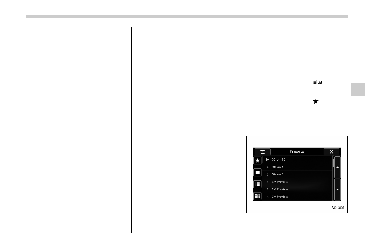
(283,1)
北米Model "A1700BE-B" EDITED: 2017/ 10/ 11
NOTE
. SiriusXM Satellite Services — De-
scriptions
– Only SiriusXM Satellite Radio
®
brings you more of what you love,
all in one place. Get over 175
channels, incl uding commer cial-
free music, plus the best sports,
news, talk, comedy and entertain-
ment. Welcome to the world of
satellite radio. More information
about SiriusXM Satellite Radio is
available online at
www.siriusxm.com (U.S.) and
www.siriusxm.ca (Canada).
. SiriusXM Satellite Services — Sub-
scription Instructions
– For SiriusXM Services requiring a
subscription (such as SiriusXM Sa-
tellite Radio, and some Infotainment
& data services), the following para-
graph shall be included.
Required SiriusXM Satellite Radio
and some Infotainment & data ser-
vices monthly subscriptions sold
separately after trial period. Sub-
scription fee is consumer only. All
fees and programming subject to
change. Subscriptions are subject
to the Customer Agreement avail-
able at www.siriusxm.com (U.S.) or
www.siriusxm.ca (Canada). Sirius,
XM and all related marks and logos
are trademarks of Sirius XM Radio
Inc. All other marks, channel names
and logos are the property of their
respective owners.
For more information, program
schedules, and to subscribe or
extend subscription after compli-
mentary trial period; more informa-
tion is available at:
. U.S. customers:
Visit www.siriusxm.com or call
1-866-635-2349
. Canadian customers:
Visit www.siriusxm.ca or call
1-877-209-0079
. SiriusXM Satellite Radio is solely
responsible for the quality, availability
and content of the satellite radio ser-
vices provided, which are subject to the
terms and conditions of the SiriusXM
Satellite Radio customer service agree-
ment.
. Customers should have their radio
ID ready; the radio ID can be found by
tuning to “Ch 000” on the radio. For
details, see “DISPLAYING THE RADIO
ID” below.
. All fees and programming are the
responsibility of SiriusXM Satellite
Radio and are subject to change.
! How to change the source
Select the “Sirius XM” key on the source
select screen. Refer to “Selecting an audio
source” F5-17.
! Presetting a channel
1. The presets list is displayed via either
of the following procedures.
. When you touch the
tab in the
SiriusXM main screen (if the list that
was displayed the last time is Presets).
. When you select the
tab in each
list screen.
2. The current channel is stored if you
touch and hold the preset list key. You can
store up to 30 channels (A beep sounds
when a channel stored).
The playing icon is displayed for the
currently selected channel.
– CONTINUED –
Audio/Audio set
5-39
5
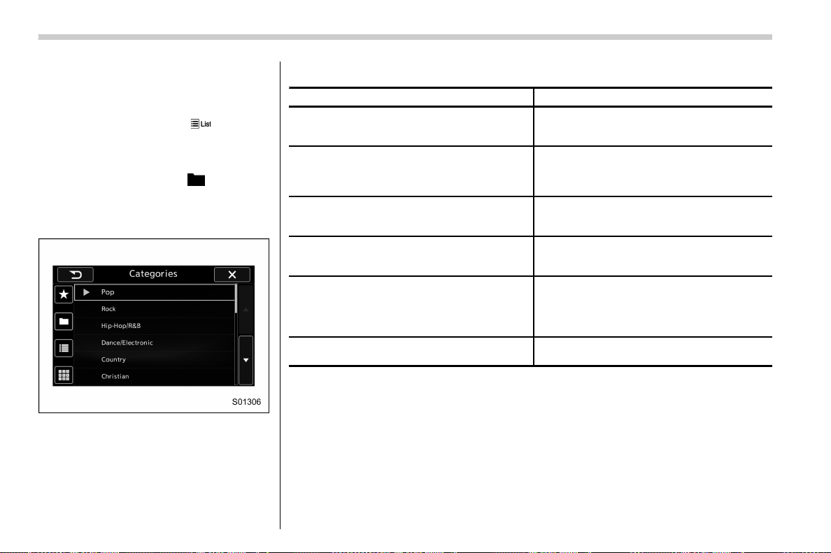
(284,1)
北米Model "A1700BE-B" EDITED: 2017/ 10/ 11
! Selecting a channel from the list
1. The categories list is displayed via
either of the following procedures.
. When you touch the
tab in the
SiriusXM main screen (if the list that
was displayed the last time is Cate-
gories).
. When you select the
tab in each
list screen.
2. Each channel list is displayed when
you select each category item.
In addition, the following messages appear.
Display Message Contents
“Subscription Update”
“Press OK to Continue”
An update to your SiriusXM subscription has
been received by the SiriusXM tuner. Touch any
key to continue.
“Channel XXX Not Available”
(“XXX” refers to the selected channel number.)
This channel is not a valid SiriusXM channel.
The channel number has been entered incor-
rectly, or the channel was removed from the
SiriusXM channel lineup.
“Channel XXX Not Subscribed Call.”
“Call SiriusXM to Subscribed.”
(“XXX” refers to the selected channel number.)
This channel is not included in your SiriusXM
subscription plan.
“Ch Locked”
“Lock Code?”
The selected channel has been locked by the
parental controls.
A prompt to enter the unlock code will appear.
“Check Antenna”
Ensure the SiriusXM antenna cable is con-
nected to the SiriusXM tuner correctly.
Check the SiriusXM antenna wire for breaks or
sharp bends.
Replace the antenna if necessary.
“No Signal”
The vehicle must be outside, and the antenna
must have a clear view of the southern sky.
NOTE
Contact SiriusXM
. Listener Care Center (U.S. customers):
1-866-635-2349
. Listener Care Centre (Canadian customers):
1-877-209-0079
Audio/Audio set
5-40
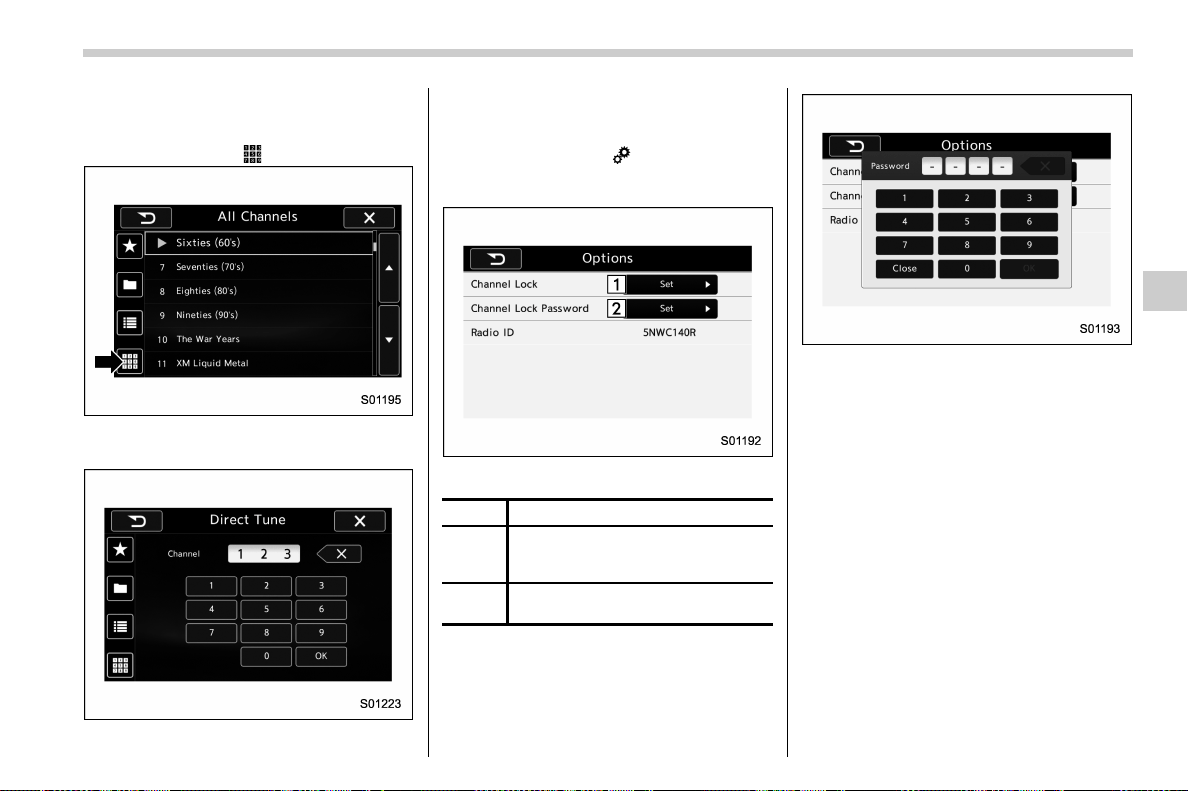
(285,1)
北米Model "A1700BE-B" EDITED: 2017/ 10/ 11
! Direct Tune
1. A channel input screen is displayed
when you touch the
tab.
2. Input any number and touch the “OK”
key, receive the channel which input.
! SXM setting
1. An option menu screen is displayed
when you touch the
tab on the lower
left side of the screen. The “Options”
screen will appear.
Option menu screen
No. Function
&
1
Set the lock function of each chan-
nel. Input the password is necessary
for operation.
&
2
Set the password of the lock func-
tion.
2. A password input screen is displayed
when you touch the “Set” key of the
Channel Lock function.
Password input screen
3. When the input password is approved,
change to the lock channel selection
screen.
– CONTINUED –
Audio/Audio set
5-41
5
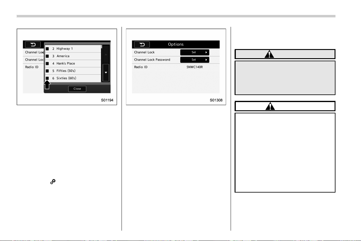
(286,1)
北米Model "A1700BE-B" EDITED: 2017/ 10/ 11
Lock channel selection screen
4. In the channel list, touch the channel
that should be locked.
! Displaying the Radio ID
Each SiriusXM tuner is identified with a
unique radio ID. The “Radio ID” is required
when activating an SiriusXM Satellite
Services or when reporting a problem.
. If “Ch 000” is selected using the AUDIO/
TUNE knob, the ID code will be displayed.
. Touch the
key. The Radio ID will be
displayed on the “Options” screen.
& aha
TM
by HARMAN
aha is a cl oud-base d application that
connects to the system and gives you
access to your favorite web content safely
and easily. There are over 30,000 stations
spanning internet radio, personalized mu-
sic, audiobooks, Facebook, Twitter, res-
taurant and hotel searches, weather and
more. For more about aha, go to the aha
site (http://www.aharadio.com).
When connecting iPhone and iPod touch
or Android devices with the aha application
installed, you can control, view, and hear
aha content through the system.
In order to connect to this system, use a
USB port for an iPhone or iPod touch and
Bluetooth for Android devices.
In this chapter, iPhone and iPod touch or
Android devices will be referred to as a
smartphone.
WARNING
Do not connect or o perate the
smartphone while driving. Doing so
may result in loss of control of your
vehicle and cause an accident or
serious injury.
CAUTION
. Do not leave your smartphone in
the car. In particular, high tem-
peratures inside the vehicle may
damage the smartphone.
. Do not push down on or apply
unnecessary pressure to the
smartphone while it is connected
as this may damage the smart-
phone or its terminal.
. Do not insert foreign objects into
the port as this may damage the
smartphone or its terminal.
Audio/Audio set
5-42
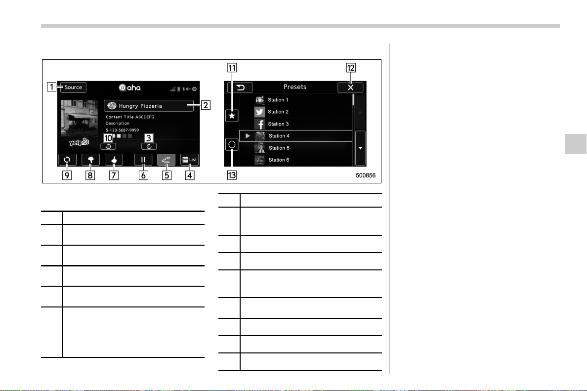
(287,1)
北米Model "A1700BE-B" EDITED: 2017/ 10/ 11
! Control screen and panel
Control screen (main screen and station screen)
No. Function
&
1
Select to display the audio source
selection screen.
&
2
Select to open the station list. Refer to
“
Using aha application” F5-47.
&
3
Select to fast forward the current con-
tent item by 30 seconds.
&
4
Select to display the contents list of the
selected station.
&
5
Select to make a phone call to the
current content item.
A phone number is distributed depend-
ing on content items.
This feature is available only in these
cases.
No. Function
&
6
The track pauses when pressed during
playback and plays back when touched
during pause.
&
7
Select to set thumbs up.
&
8
Select to set thumbs down.
&
9
Select to start the playback from the
beginning of the content in the target
station.
&
10
Select to rewind the current content item
by 15 seconds.
&
11
Select to display the preset list.
&
12
Return to the control screen.
&
13
Select to display the nearby list.
– CONTINUED –
Audio/Audio set
5-43
5
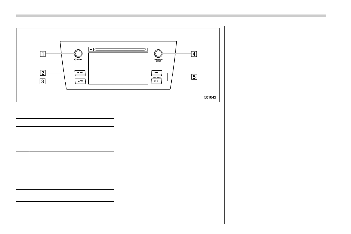
(288,1)
北米Model "A1700BE-B" EDITED: 2017/ 10/ 11
Audio panel
No. Function
&
1
Turn to adjust volume.
Press to turn the audio system on/off.
&
2
Press to display the sound setting
screen. Refer to “
Unit settings” F5-18.
&
3
Press to display the station operation
screen.
Press to select an audio mode.
&
4
Turn to display the next/previous con-
tent item.
Press to select an audio source. Refer
to “
Selecting an audio source” F5-17.
&
5
Press to display the next/previous con-
tent item.
NOTE
. For safety reasons, certain func-
tions are n ot available while your
vehicle is in motion.
. In order to maximize signal recep-
tion, performance and precision of the
smartphone, please ensure the smart-
phone is placed as close to the system
as possible, while ensuring it is stowed
and secure while driving.
. When the ignition switch is in the
“ACC” or “ON” position, the battery of
the connected iPhone/iPod touch is
charged.
. iPhone/iPod touch may not be re-
cognized when the ignition switch is in
the “ACC” or “ON” position. In this
case, remove the iPhone/iPod touch
and reconnect it.
. The accuracy of the displayed in-
formation or the signal reception per-
formance depends on the smartphone
or the connected device, and it’s wire-
less connection.
. Since the aha application uses sig-
nals from GPS satellites and wireless
communication lines, it may not work
properly in the following locations.
– In a tunnel
– In underground parking lots
Audio/Audio set
5-44

(289,1)
北米Model "A1700BE-B" EDITED: 2017/ 10/ 11
– Outside wireless communication
range, such as some countryside
areas
– Where the wireless communica-
tion network is congested, or where
communications are restricted
. Depending on the circumstances
and environment, the signal may be
weak or not be received. In such cases,
an error may occur.
. Top 35 entries in the preset station
list on the smartphone are displayed.
When there are more than 35 entries in
the preset station list, change the order
of the entries in the list on the smart-
phone. You can change the priority of
your preset stations within the aha
appli cation (after disconnected from
this system) to modify the station list
shown on the screen. Please see your
smartphone aha application “Edit Pre-
sets (in Main menu)” to modify this list.
. For operating the smartphone, see
the instruction manual that comes with
it.
. If th ere are multip le music file s
stored on your iPhone or iPod touch,
it may take some time until playback
starts.
. Playback may be intermittent when
you switch to streaming Bluetooth
audio from aha on your smartphone
device.
. When connecting the device via
Bluetooth, the communication speed
may become slower than via USB.
! Before using aha application
In order to use the aha application on this
system, the application must be installed
on the smartphone.
! Settings required to use aha
application
. Search and download the aha applica-
tion from your smartphone app store.
– iPhone and iPod touch: Apple App
Store via iTunes
– Android device: Google Play Store
. Create an account and login to the aha
application on the smartphone.
NOTE
Please use the latest version of the aha
application.
! About app-based connected con-
tent
Requirements for using the connected
content services of the aha application on
this system.
. Latest version of the system is compa-
tible with connected content application(s)
for the smartphone, available from aha,
downloaded to your smartphone.
. A current account with a wireless
content service provider.
. A smartphone data plan: If the data plan
for your smartphone does not provide for
unlimited data usage, additional charges
from your carrier may apply for accessing
app-based connected content via 3G, 4G,
Wi-Fi or 4G LTE wireless networks.
. Connection to the internet via 3G, 4G,
Wi-Fi or 4G LTE networks.
NOTE
. Changes to product specifications
may result in differences between the
content of the manual and features of
the product.
. Be careful not to exceed the data
usage limits for your smartphone.
Doing so will result in additional data
usage charges from your phone carrier.
. Access to app-based connected
content will depend on the availability
of wireless cell and/or Wi-Fi network
coverage for the purpose of allowing
your smartphone to connect to the
internet.
. Service availability may be geogra-
phically limited by region. Consult the
wireless connected content service
provider for additional information.
. Ability of this product to access
– CONTINUED –
Audio/Audio set
5-45
5
(290,1)
北米Model "A1700BE-B" EDITED: 2017/ 10/ 11
connected content is subject to change
without notice and could be affected by
any of the following: compatibility
issues with future firmware versions
of the smartphone; compatibility is-
sues with future versions of the con-
nected content application(s) for the
smartphone; changes to or disconti-
nuation of the connected content ap-
plication(s) or service by its provider.
. Communication and phone call
charges for smartphones should be
paid by the wireless subscriber.
. If you lose the data in a smartphone
or other device while using it with the
system, no compensation will be given
for the lost data.
. SUBARU CORPORATION makes no
guarantee regarding the content pro-
vided by aha.
. aha may not work due to factors on
smartphones, smartphone applica-
tions or stations. SUBARU CORPORA-
TION is not responsible for it.
! About the supported devices
This system supports the following de-
vices.
. For iPhone/iPod touch users
Type Generation
Firmware
version or
OS
iPhone
iPhone 3G iOS 4.2.x
iPhone 3GS iOS 6.1.x
iPhone 4 iOS 7.0.x
iPhone 4s iOS 7.0.x
iPhone 5 iOS 7.0.x
iPhone 5c iOS 7.0.x
iPhone 5s iOS 7.0.x
iPod touch
iPod touch iOS 3.1.x
iPod touch 2 iOS 4.2.x
iPod touch 3 iOS 5.1.x
iPod touch 4 iOS 6.1.x
iPod touch 5
iOS 7.0.x
NOTE
Note that the warranty does not apply if
an unsupported iPhone/iPod touch is
connected.
. For Android device users
Android OS Specification Profile
Android
Ver. 2.2 or
Ver. 2.3
Bluetooth
Specification
Ver. 1.1 or
higher
(Ver. 2.0 +
EDR or higher
is recom-
mended)
. aha Con-
nect Bin-
ary API
over SPP
. Digital
audio by
A2DP
NOTE
The available functions may vary de-
pending on the type of Android device.
! Connecting a smartphone
If you connect a smartphone to this system
after starting a supported aha application
on the smartphone, you can display and
operate the aha application displayed on
the smartphone on the system screen.
1.Runtheahaapplicationonyour
smartphone.
2. Connect the iPhone/iPod touch to the
USB port or connect the Android device by
utilizing the Bluetooth connection (SPP
and A2DP profile).
. For details about connecting an
iPhone/iPod touch: Refer to “Connect-
ing and disconnecting a USB memory/
portable device” F5-16.
. For details about registering or con-
Audio/Audio set
5-46
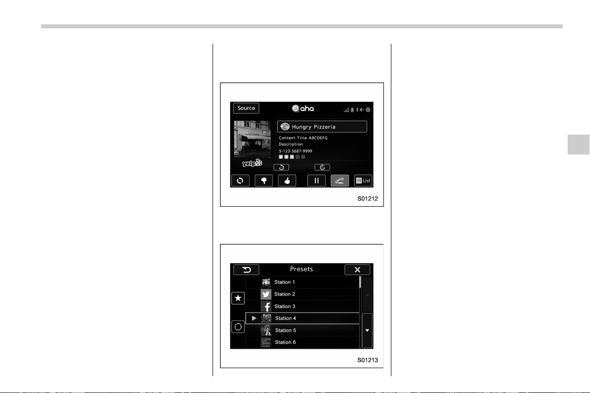
(291,1)
北米Model "A1700BE-B" EDITED: 2017/ 10/ 11
necting an Android device: Refer to
“Registering/connecting Bluetooth
®
device” F5-64.
NOTE
When iPhone/iPod touch and Android
devices are connected at the same
time, iPhone/iPod touch is prioritized.
! How to change the source
. Select the “aha” key on the source
select screen. Refer to “Basic operation”
F5-17.
. Select the “aha” key on the APPS
screen. Refer to “SUBARU STARLINK”
F5-25.
NOTE
When starting-up “aha”, there are some
smartphone models for which “aha”
application does not start up automati-
cally.
! Using aha application
1. When the top screen is displayed,
touch the station key.
Example of the main screen
2. Select the desired station from the list.
The selected station is displayed.
NOTE
. The following operations are not
available on this system. Perform these
operations on the smartphone.
– Add/Reorder/Delete stations
– Login to Facebook/Twitter
. For the aha function, the following
touch screen gestures are not avail-
able.
– Multi-touch operation
– Double-tap
. For details on the services or the
operations, check the aha site
(http://www.aharadio.com) on the inter-
net.
. The button display will vary depend-
ing on each station or content item.
– CONTINUED –
Audio/Audio set
5-47
5
(292,1)
北米Model "A1700BE-B" EDITED: 2017/ 10/ 11
& Pandora
®
(if equipped)
Pandora is an application for a smart-
phone. This can automatically select and
play recommended tracks.
By rating the track currently playing, tracks
that better match your preference will be
recommended.
In order to connect to this system, use a
USB port for an iPhone or iPod touch and
Bluetooth for Android devices.
Depending on differences between mod-
els or software version etc., some models
might be incompatible with this system.
This function is not available if the Pandora
application has not been installed on the
smartphone.
WARNING
Do not operate the player’s controls
or connect the smartphone while
driving. Doing so may result in loss
of control of your vehicle and cause
an accident or serious injury.
CAUTION
. Do not leave your smartphone in
the car. In particular, high tem-
peratures inside the vehicle may
damage the smartphone.
. Do not push down on or apply
unnecessary pressure to the
smartphone while it is connected
as this may damage the smart-
phone or its terminal.
. Do not insert foreign objects into
the port as this may damage the
smartphone or its terminal.
NOTE
Follow the specific operation proce-
dures for the smartphone application.
Audio/Audio set
5-48
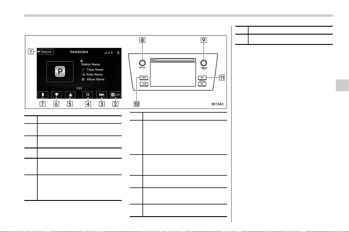
(293,1)
北米Model "A1700BE-B" EDITED: 2017/ 10/ 11
! Control screen and audio panel
No. Function
&
1
Select to display the audio source
selection screen.
&
2
Select to open the station list. Refer to
“
Station list” F5-50.
&
3
Select to skip the current track.
&
4
The track pauses when touched during
playback and plays when touched dur-
ing pause.
&
5
Select to set thumbs up.
This gives a high rating to the current
song.
All other similar songs will be played
back more frequently.
No. Function
&
6
Select to set thumbs down.
This gives a low rating to the current
song.
All other similar songs will be played
back less frequently.
When you select thumbs down, the
current track is skipped.
&
7
During playback of a station, you can
use this key to bookmark a song or
artist. Refer to “
Registering Bookmarks”
F5-50.
&
8
Turn to adjust volume.
Press to turn the audio system on/off.
&
9
Turn clockwise to skip to the next track.
Press to select an audio source. Refer
to “
Selecting an audio source” F5-17.
&
10
Press to display the sound setting
screen. Refer to “
Unit settings” F5-18.
No. Function
&
11
Press to skip to the next track/cover art.
! Connecting a smartphone
Connect the iPhone/iPod touch to the USB
port or connect the Android device by
using Bluetooth connection (SPP and
A2DP profile).
. For details about connecting an
iPhone/iPod touch: Refer to “Connecting
and disconnecting a USB memory/porta-
ble device” F5-16.
. For details about registering or con-
necting an Android device: Refer to “Re-
gistering/connecting Bluetooth
®
device”
F5-64.
! How to change the source
The Pandora operation screen can be
reached by the following methods:
. Connecting a Pandora device. Refer to
“Connecting a Bluetooth device” F5-67 or
“Connecting and disconnecting a USB
memory/portable device” F5-16.
. Select the “Pandora” key on the source
select screen. Refer to “Selecting an audio
source” F5-17.
. Select the “Pandora” key on the APPS
screen. Refer to “SUBARU STARLINK”
F5-25.
– CONTINUED –
Audio/Audio set
5-49
5
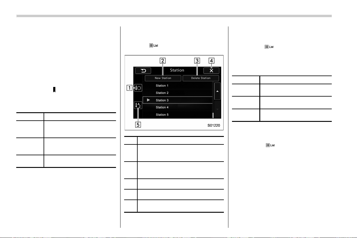
(294,1)
北米Model "A1700BE-B" EDITED: 2017/ 10/ 11
NOTE
When starting-up Pandora, there are
some smartphone models for which
Pandora application does not start up
automatically.
! Registering Bookmarks
You can register the music and artist now
being played in Bookmark.
1. Touch the
tab.
2. Select the desired key. The following
items are appeared on the screen.
Item Function
Track
When selected after the Book-
mark key is pressed, the current
track is bookmarked.
Artist
When selected after the Book-
mark key is pressed, the current
artist is bookmarked.
Cancel
Select to cancel the bookmark
operation.
! Station list
You can select, add or delete a station.
When the
tab is touched on the main
screen, a station list will be displayed.
No. Function
&
1
Select to sort the list in the chronological
order of when the Station List was
created.
&
2
Select to create a station.
The station can be created using track
names or artist names.
&
3
Select to delete a station.
&
4
Return to the control screen.
&
5
Select to sort the list based on the
alphabetical order of the station names.
! Store the station
You can register a station.
1. Touch the
tab on the Pandora main
screen.
2. Touch the “New Station” key, and then
select the desired key.
Item Function
From Track
Select to create a station using a
track name.
From Artist
Select to create a station using
an artist name.
Cancel
Select to cancel the operation to
add a station.
! Delete the station
You can delete a station.
1. Touch the
tab on the Pandora top
screen.
2. Touch the “Delete Station” key, and
then the station list is appeared.
3. Select the item to delete the station. If
the confirmation screen appears and the
“OK” key is selected, the selected station
will be deleted from station list.
Audio/Audio set
5-50
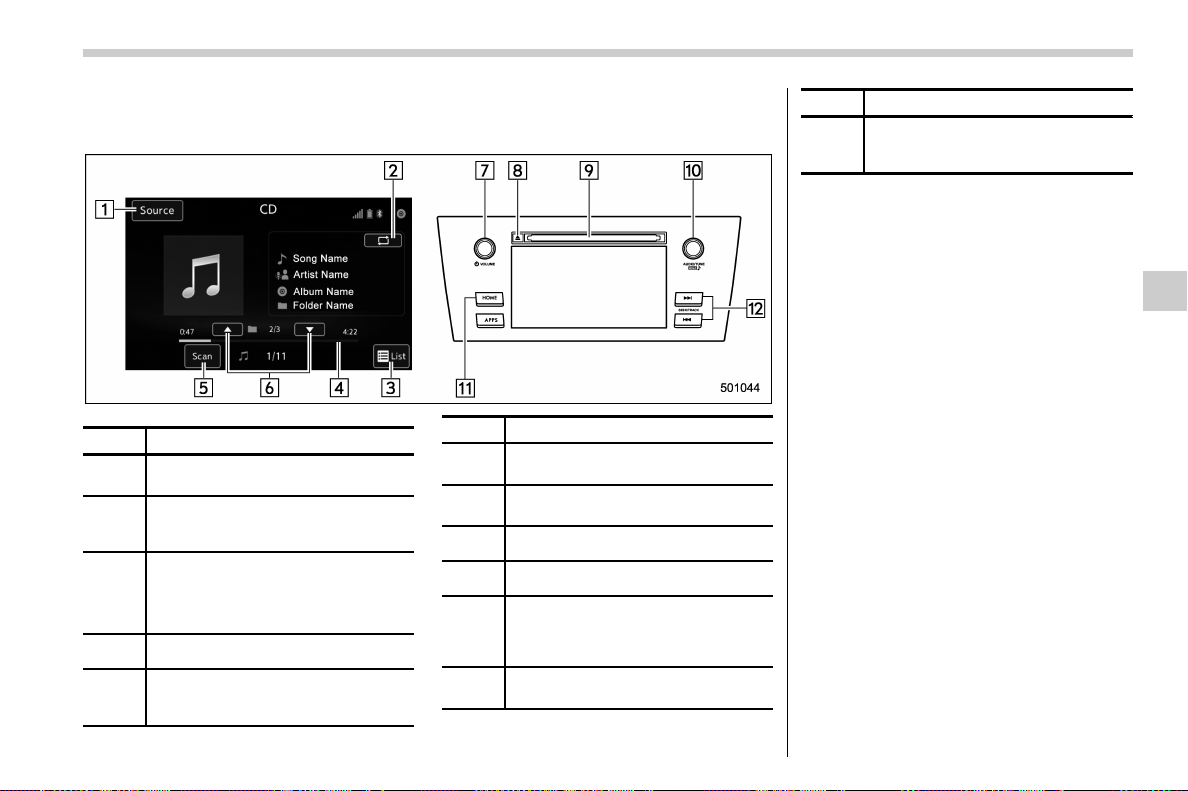
(295,1)
北米Model "A1700BE-B" EDITED: 2017/ 10/ 11
& CD
! Control screen and audio panel
No. Function
&
1
Select to display the audio source
selection screen.
&
2
Select to display the play mode
currently selected. Refer to “
Select
play mode” F5-52.
&
3
Audio CD:
Select to display a track list.
MP3/WMA/AAC disc:
Select to display a folder list.
&
4
Shows progress.
&
5
The tracks in the disc are played back
for 10 seconds each from the begin-
ning of the track.
No. Function
&
6
MP3/WMA/AAC disc:
Select to choose a folder.
&
7
Turn to adjust volume.
Press to turn the audio system on/off.
&
8
Press to eject a disc.
&
9
Disc slot
&
10
Turn to select a track/file.
Press to select an audio source.
Refer to “
Selecting an audio source”
F5-17.
&
11
Press to display the sound setting
screen. Refer to “
Unit settings” F5-18.
No. Function
&
12
Press to select a track/file.
Press and hold to fast forward/re-
wind.
NOTE
. Depending on the compression data
format of the inserted CD, some keys
may not be displayed on the screen.
. If a disc contains CD-DA files and
MP3/WMA/AAC files, only the CD-DA
files can be played back.
. If a CD-TEXT disc is inserted, the title
of the disc and track will be displayed.
Up to 32 characters can be displayed.
. If the disc contains no CD-TEXT, only
the track number would be displayed
on the screen.
– CONTINUED –
Audio/Audio set
5-51
5
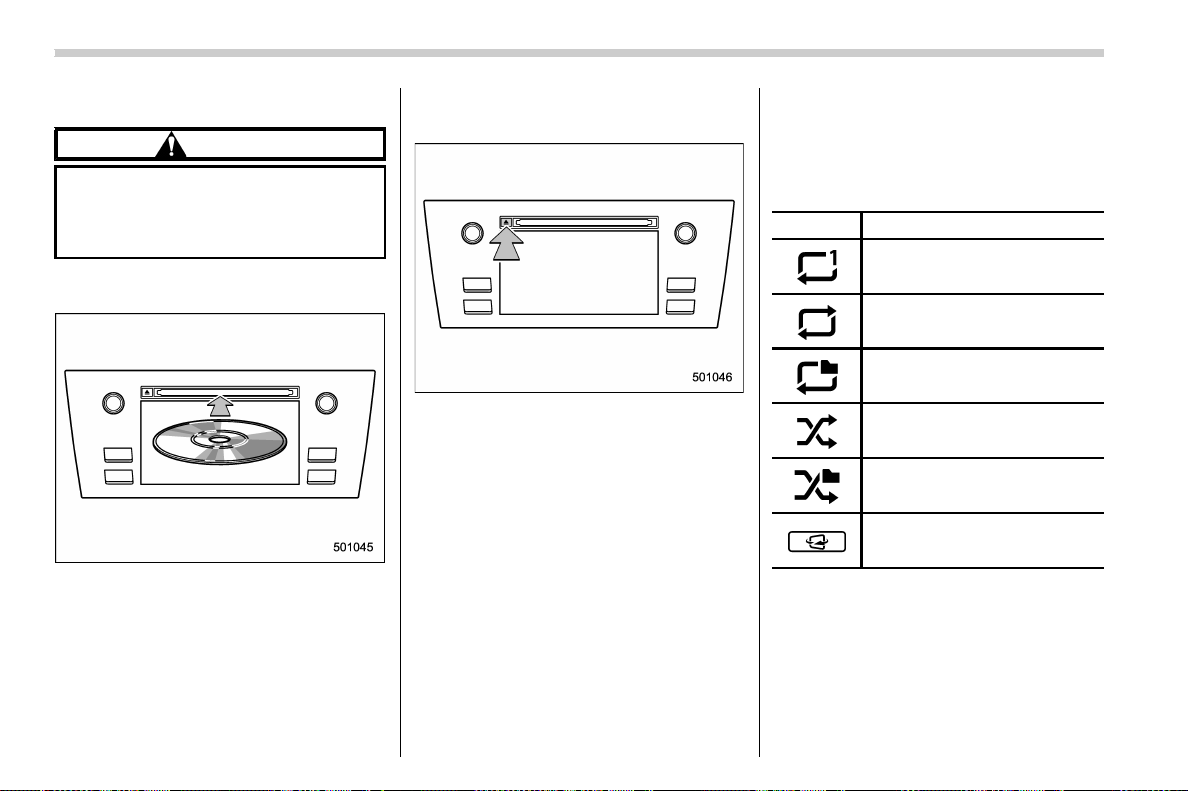
(296,1)
北米Model "A1700BE-B" EDITED: 2017/ 10/ 11
! Loading a disc
CAUTION
Never try to disassemble the audio
kit or lubricate any part of the CD
player. Do not insert anything other
than a disc into the slot.
Insert a disc into the disc slot. After
insertion, the disc is automatically loaded.
NOTE
When inserting a disc, gently insert it
with the label facing up.
! Unloading a disc
Press the eject button to remove the disc.
! How to change the source
The CD operation screen can be reached
by the following methods:
. Insert a disc. Refer to “Loading a disc”
F5-52.
. Select the “DISC” key on the source
select screen. Refer to “Selecting an audio
source” F5-17.
! Select play mode
The play mode settings display will appear
when play mode key is touched. Select the
preferred play mode from the following
items.
Icon Function
Touch to start 1 track repeat.
Touch to start repeat all.
Touch to start folder repeat.
Touch to start shuffle all.
Touch to start shuffle folder.
Return to the control screen.
NOTE
Depending on the compression data
formant of the inserted CD, the dis-
played play mode may differ from the
illustration shown here.
Audio/Audio set
5-52
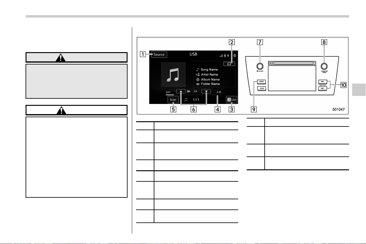
(297,1)
北米Model "A1700BE-B" EDITED: 2017/ 10/ 11
& USB memory
Audio files on the USB memory can be
played.
WARNING
Do not operate the player’s controls
or connect the USB memory while
driving. Doing so may result in
losing control of your vehicle and
cause an accident or serious injury.
CAUTION
. Do not leave your USB memory in
the car. In particular, high tem-
peratures inside the vehicle may
damage the USB memory.
. Do not push down on or apply
unnecessary pressure to the USB
memory while it is connected as
this may damage the USB mem-
ory or its terminal.
. Do not insert foreign objects into
the port as this may damage the
USB memory or its terminal.
! Control screen and audio panel
No. Function
&
1
Select to display the audio source
selection screen.
&
2
Select to display the play mode
currently selected. Refer to “
Select
play mode” F5-54.
&
3
Select to display folder list.
&
4
Shows progress.
&
5
The tracks in the folder are played
back 10 seconds each from the
beginning of the track.
&
6
Select to choose a folder.
&
7
Turn to adjust volume.
Press to turn the audio system on/off.
No. Function
&
8
Turn to select a file/track.
Press to select an audio source. Refer
to “Selecting an audio source” F5-17.
&
9
Press to display the sound setting
screen. Refer to “
Unit settings” F5-18.
&
10
Press to select a file/track.
Press and hold to fast forward/rewind.
– CONTINUED –
Audio/Audio set
5-53
5
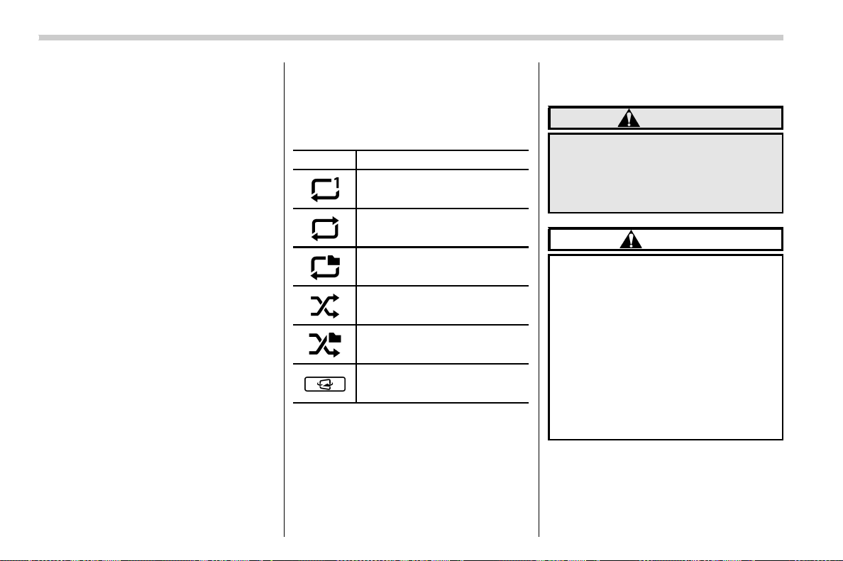
(298,1)
北米Model "A1700BE-B" EDITED: 2017/ 10/ 11
! Connecting a USB device
You can connect a USB device to the
vehicle USB port. Refer to “Connecting
and disconnecting a USB memory/porta-
ble device” F5-16.
! How to change the source
The USB Audio playback screen can be
reached by the following methods:
. Connect a USB memory. Refer to
“Connecting and disconnecting a USB
memory/portable device” F5-16.
. Sel ect the “USB/iPod” key on the
source select screen. Refer to “Selecting
an audio source” F5-17.
! Select play mode
The play mode settings display will appear
when play mode key is touched. Select the
preferred play mode from the following
items.
Icon Function
Touch to start 1 track repeat.
Touch to start repeat all.
Touch to start folder repeat.
Touch to start shuffle all.
Touch to start shuffle folder.
Return to the control screen.
& iPod
Audio files on the iPod can be played.
WARNING
Do not operate the player’s controls
or connect the iPod while driving.
Doing so may result in loss of
control of your vehicle and cause
an accident or serious injury.
CAUTION
. Do not leave your portable player
in the car. In particular, high
temperatures inside the vehicle
may damage the portable player.
. Do not push down on or apply
unnecessary pressure to the por-
table player while it is connected
as this may damage the portable
player or its terminal.
. Do not insert foreign objects into
the port as this may damage the
portable player or its terminal.
Audio/Audio set
5-54
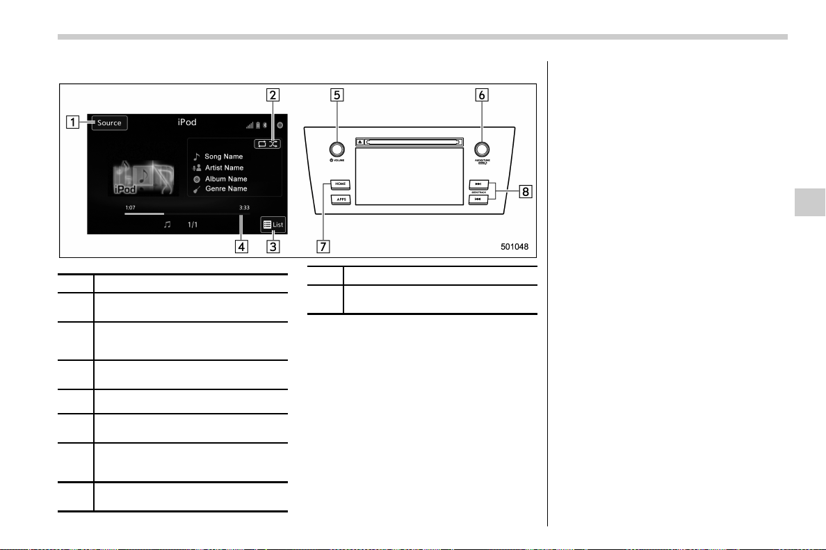
(299,1)
北米Model "A1700BE-B" EDITED: 2017/ 10/ 11
! Control screen and audio panel
No. Function
&
1
Select to display the audio source
selection screen.
&
2
Select to display the play mode cur-
rently selected. Refer to “
Select play
mode” F5-56.
&
3
Select to display iPod List. Refer to
“
iPod settings” F5-56.
&
4
Shows progress.
&
5
Turn to adjust volume.
Press to turn the audio system on/off.
&
6
Turn to select a track/file.
Press to select an audio source. Refer
to “Selecting an audio source” F5-17.
&
7
Press to display the sound setting
screen. Refer to “
Unit settings” F5-18.
No. Function
&
8
Press to select a track/file.
Press and hold to fast forward/rewind.
NOTE
. When an iPod is connected using a
genuine USB cable, the iPod starts
charging its battery.
. When an iPod is connected and the
audio source is changed to iPod mode,
the iPod will resume playing from the
same point it was last used.
. Depending on the iPod that is con-
nected to the system, certain functions
may not be available.
. Files/tracks selected by operating a
connected iPod may not be recognized
or displayed properly.
! Connecting the iPod
You can connect an iPod to the vehicle
USB port using the USB cable. Refer to
“Connecting and disconnecting a USB
memory/portable device” F5-16.
– CONTINUED –
Audio/Audio set
5-55
5
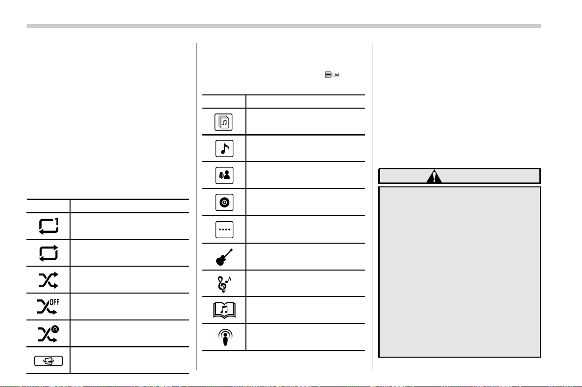
(300,1)
北米Model "A1700BE-B" EDITED: 2017/ 10/ 11
! How to change the source
The iPod operation screen can be reached
by the following methods:
. Connect an iPod. Refer to “Connecting
and disconnecting a USB memory/porta-
ble device” F5-16.
. Sel ect the “USB/iPod” key on the
source select screen. Refer to “Selecting
an audio source” F5-17.
! Select play mode
The play mode settings display will appear
when play mode key is touched. Select the
preferred play mode from the following
items.
Icon Function
Touch to start 1 track repeat.
Touch to start repeat all.
Touch to start shuffle all.
Touch to turn off shuffle.
Touch to start shuffle album.
Return to the control screen.
! iPod settings
You can choose the following items from
the list screen after touching the
tab on
the screen.
Icon Function
Select to display the play list.
Select to display tracks list.
Select to display artists list.
Select to display albums list.
Select to open other list (“Gen-
res”, “Composers”, “Audiobooks”
and “Podcast”).
Select to open “Genres” list.
Select to open “Composers” list.
Select to open “Audiobooks” list.
Select to open “Podcasts” list.
& Bluetooth audio
The Bluetooth audio system enables users
to enjoy listening to music that is played on
a portable player on the vehicle speakers
via wireless communication.
This audio system supports Bluetooth, a
wireless data system capable of playing
portable audio music without cables. If
your device does not support Bluetooth,
the Bluetooth audio system will not func-
tion.
WARNING
. Do not operate the player’s con-
trols or connect to the Bluetooth
audio system while driving.
Doing so may result in loss of
control of your vehicle and cause
an accident or serious injury.
. Your audio unit is fitted with
Bluetooth antennas. People with
implantable cardiac pacemakers,
cardiac resynchronization ther-
apy-pacemakers or implantable
cardioverter defibrillators should
maintain a reasonable distance
between themselves and the
Bluetooth a ntennas. The r adio
waves may affect the operation
of such devices.
Audio/Audio set
5-56
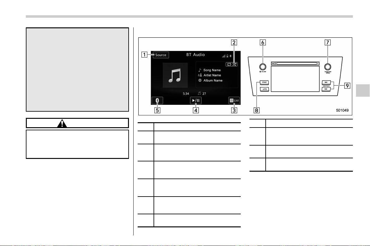
(301,1)
北米Model "A1700BE-B" EDITED: 2017/ 10/ 11
. Before using Bluetooth devices,
users of any electrical medical
device other than implantable
cardiac pacemakers, cardiac re-
synchronization therapy-pace-
makers or implantable cardiover-
ter defibrillators should consult
the manufacturer of the device
for information about its opera-
tion under the influence of radio
waves. Radio waves could have
unexpected effects on the opera-
tion of such medical devices.
CAUTION
Do not leave your portable player in
the vehicle. In particular, high tem-
peratures inside the vehicle may
damage the portable player.
! Control screen and audio panel
No. Function
&
1
Select to display the audio source
selection screen.
&
2
Select to display the play mode cur-
rently selected. Refer to “
Select play
mode” F5-58.
&
3
Select to display as a list (for the
models with AVRCP Ver. 1.4 or high-
er).
&
4
The track pauses when touched during
playback and plays when touched
during pause.
&
5
Select to open Bluetooth Settings.
Refer to “
Setting Bluetooth details” F5-
67.
&
6
Turn to adjust volume.
Press to turn the audio system on/off.
No. Function
&
7
Turn to select a track.
Press to select an audio source. Refer
to “Selecting an audio source” F5-17.
&
8
Select to display the sound setting
screen. Refer to “
Unit settings” F5-18.
&
9
Press to select a track.
Press and hold to fast forward/rewind.
– CONTINUED –
Audio/Audio set
5-57
5
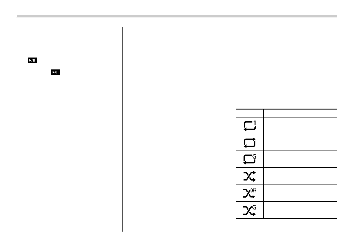
(302,1)
北米Model "A1700BE-B" EDITED: 2017/ 10/ 11
NOTE
. Depending on the Bluetooth device
that is connected to the system, the
music may start playing when selecting
the
key while it is paused. Con-
versely, the music may pause when
selecting the
key while it is playing.
. In the following conditions, the sys-
tem may not function:
– The Bluetooth device is turned
off.
– The Bluetooth device is not con-
nected.
– The Bluetooth device has a low
battery.
. It may take time to connect the
phone when Bluetooth audio is being
played.
. For operating the portable player,
see the instruction manual that comes
with it.
. If the Bluetooth device is discon-
nected due to poor reception from the
Bluetooth network when the ignition
switch is in the “ACC” or “ON” position,
the system will automatically recon-
nect to the portable player.
. If the Bluetooth device is discon-
nected on purpose, such as it was
turned off, this does not happen. Re-
connect the portable player manually.
. Bluetooth device information is re-
gistered when the Bluetooth device is
connected to the Bluetooth audio sys-
tem. When selling or disposing of the
vehicle, remove the Bluetooth audio
information from the system. Refer to
“Bluetooth
®
settings” F5-64.
! Connecting a Bluetooth device
To use the Bluetooth audio system, it is
necessary to register a Bluetooth device
with the system.
. Registering an additional device
1. Select the “Add” key on the Bluetooth
devices connection screen.
2. For more information: Refer to “Regis-
tering/connecting Bluetooth
®
device” F5-
64.
. Selecting a registered device
1. Select the “Select” key on the Blue-
tooth devices connection screen.
2. For more information: Refer to “BT
Devices Connection screen” F5-67.
! How to change the source
Select the “BT Audio” key on the source
select screen. Refer to “Selecting an audio
source” F5-17.
NOTE
Depending on the typ e of portable
player connected, s ome functions
may not be available and/or the screen
may look differently than shown in this
manual.
! Select play mode
The play mode settings display will appear
when play mode key is touched. Select the
preferred play mode from the following
items.
Icon Function
Touch to start 1 track repeat.
Touch to start repeat all.
Touch to repeat the tracks in the
group.
Touch to start shuffle all.
Touch to play tracks in the order
in which they are registered in the
audio device.
Touch to start shuffle group.
Audio/Audio set
5-58
(303,1)
北米Model "A1700BE-B" EDITED: 2017/ 10/ 11
Icon Function
Return to the control screen.
NOTE
If the connected device does not sup-
port the group repeat mode, the group
functions are not available.
& AUX
WARNING
Do not operate the player’s controls
or connect the portable audio device
while driving. Doing so may result in
loss of control of your vehicle and
cause an accident or serious injury.
CAUTION
. Do not leave portable audio de-
vice in the vehicle. The tempera-
ture inside the vehicle may be-
come high, resulting in damage
to the player.
. Do not push down on or apply
unnecessary pressure to the por-
table audio device while it is
connected as this may damage
the portable audio device or its
terminal.
. Do not insert foreign objects into
the port as this may damage the
portable audio device or its term-
inal.
– CONTINUED –
Audio/Audio set
5-59
5
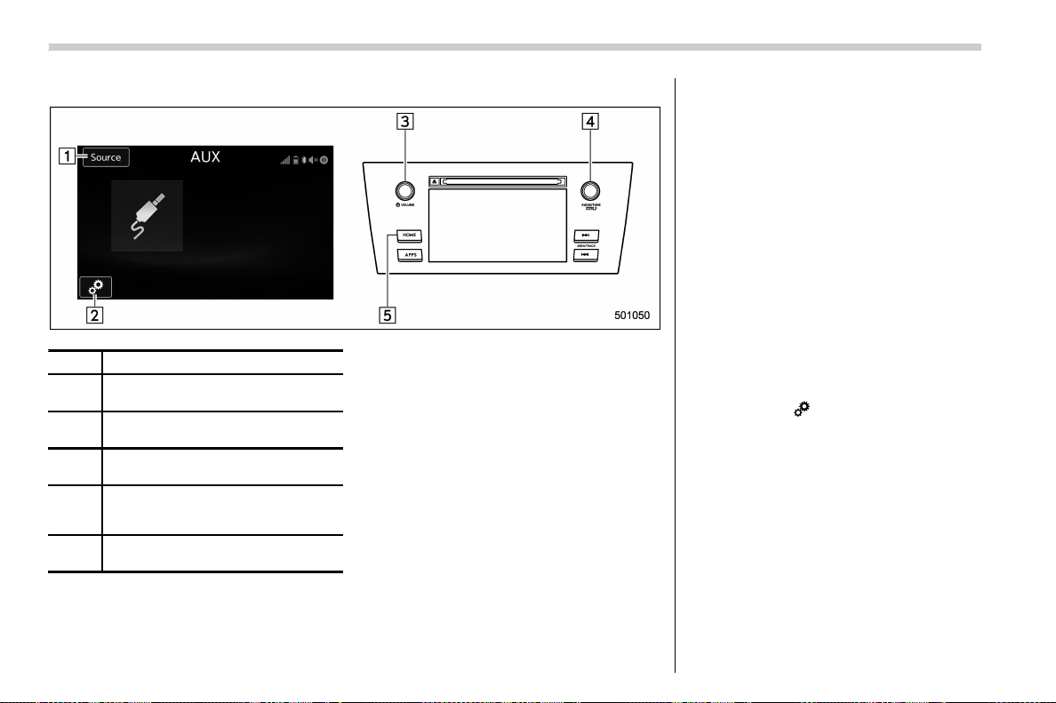
(304,1)
北米Model "A1700BE-B" EDITED: 2017/ 10/ 11
! Control screen and audio panel
No. Function
&
1
Select to display the audio source
selection screen.
&
2
Select to adjust the audio gain level.
Refer to “
Audio level settings” F5-60.
&
3
Turn to adjust volume.
Press to turn the audio system on/off.
&
4
Press to select an audio source.
Refer to “
Selecting an audio source”
F5-17.
&
5
Press to display the sound setting
screen. Refer to “
Unit settings” F5-18.
! Connecting a portable audio device
You can connect a portable audio device to
the vehicle AUX jack. Refer to “Connecting
and disconnecting a USB memory/porta-
ble device” F5-16.
! How to change the source
The AUX operation screen can be reached
by the following methods:
. Connect a portable audio device. Refer
to “Connecting and disconnecting a USB
memory/portable device” F5-16.
. Select the “AUX” key on the source
select screen. Refer to “Selecting an audio
source” F5-17.
! Audio level settings
You can set the audio gain level.
1. Select the
tab on the screen, and
then touch the right side key of the “Audio
Level” key.
2. Select the audio level from the follow-
ing items.
. Low
. Mid
. High
Audio/Audio set
5-60
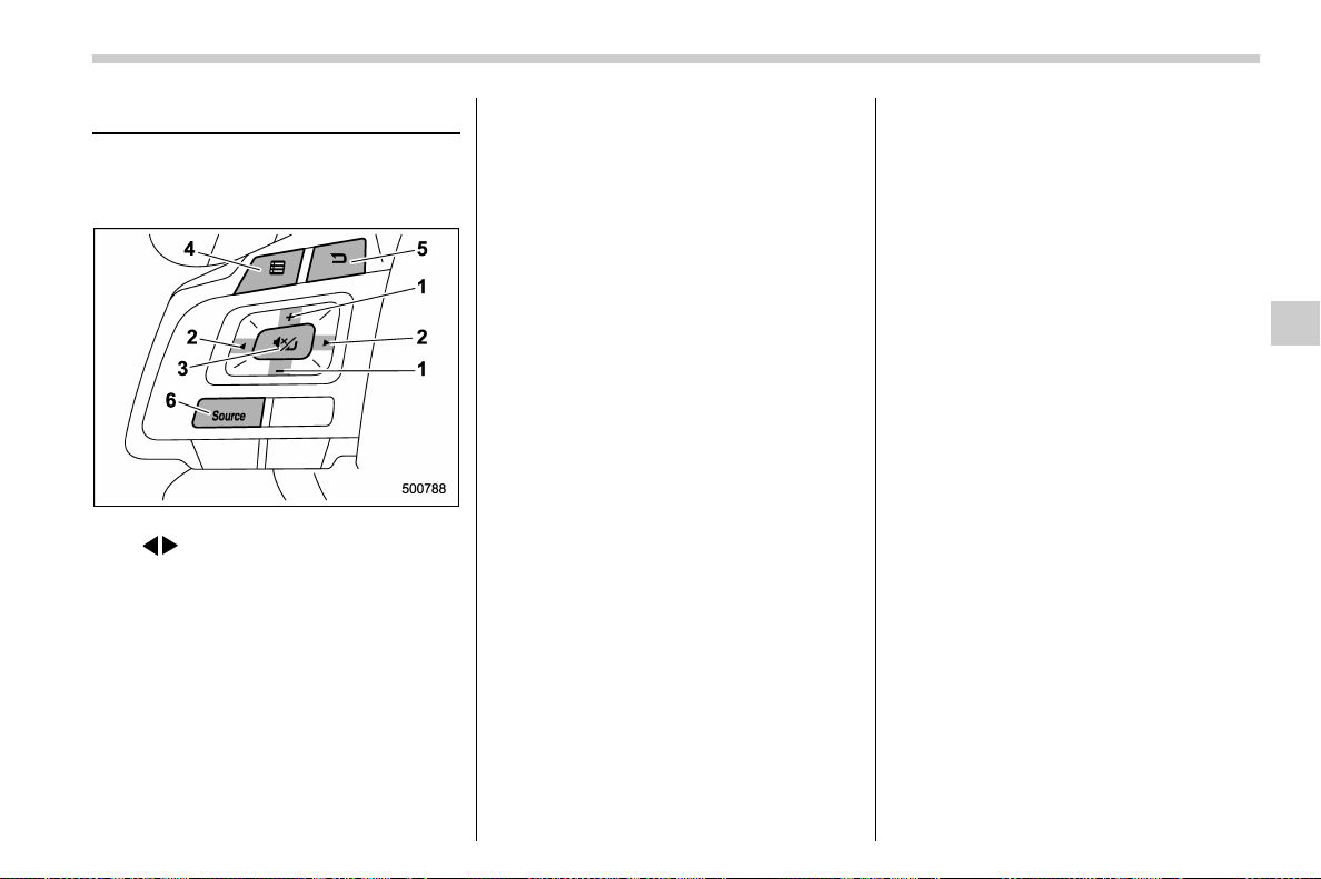
(305,1)
北米Model "A1700BE-B" EDITED: 2017/ 10/ 11
Steering switches for audio
Some parts of the audio/visual system can
be adjusted using the switches on the
steering wheel.
1) + − switch
2)
/ switch
3) Mute/Enter switch
4) List switch
5) Back switch
6) Source switch
– CONTINUED –
Audio/Steering switches for audio
5-61
5

(306,1)
北米Model "A1700BE-B" EDITED: 2017/ 10/ 11
. +/− switch
Mode Operation Function
Except list screen
Press Volume up/down
Press and hold Volume up/down continuously
List screen Press Move cursor up/down
Pandora main screen (if equipped) Press and hold
“+” switch is thumb up/“−” switch is thumb down
. / switch
Mode Operation Function
AM/FM Radio, SiriusXM (if equipped)
Press Preset channel up/down
Press and hold
Seek up/down continuously while the switch is
being pressed
aha
Press Content up/down
Press and hold
Reverse the current content item for 15 seconds/
Fast forward the current content item for 30
seconds
Audio CD, MP3/WMA/AAC disc, USB, iPod, BT
audio
Press Select a track/file
Press and hold Fast forward/rewind
Pandora (if equipped) Press and hold Thumbs up
List screen Press
Move cursor left/right
Audio/Steering switches for audio
5-62

(307,1)
北米Model "A1700BE-B" EDITED: 2017/ 10/ 11
. Mute/Enter switch
Mode Operation Function
List screen Press Select cursor entry
CD, USB, iPod, BT audio, Pandora (if equipped), aha Press Pause or play back
AM/FM radio, AUX, SiriusXM (if equipped) Press
Mute or cancel mute
. Back switch
Mode Operation Function
All (except for SUBARU STARLINK) Press Return to the previous screen
All Press and hold
Return to the HOME screen
. List switch
Mode Operation Function
All (except for SUBARU STARLINK) Press
Show list screen
. Source switch
Mode Operation Function
All Press
Change audio modes
NOTE
In the aha, Pandora (if equipped) and SUBARU STARLINK (if equipped) mode, some operation may be done on the screen
depend on the selected APPS.
Audio/Steering switches for audio
5-63
5
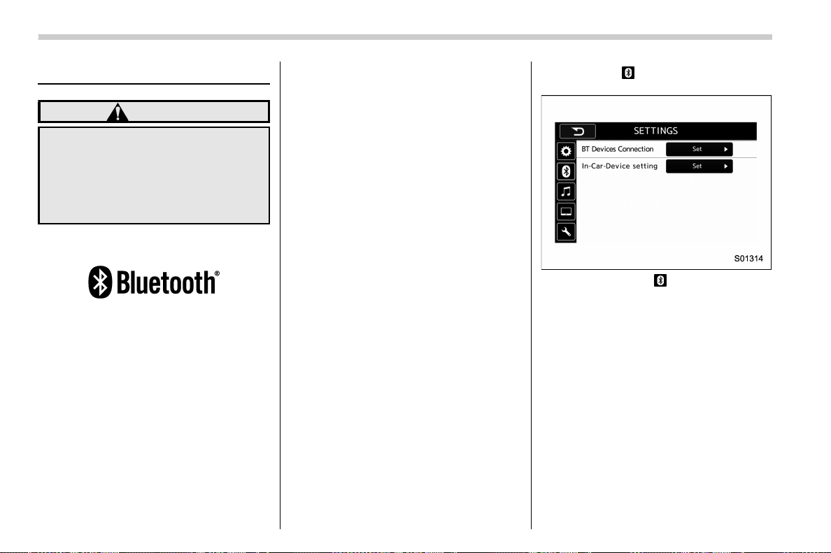
(308,1)
北米Model "A1700BE-B" EDITED: 2017/ 10/ 11
Bluetooth
®
settings
WARNING
Be sure to park the vehicle in a safe
location before connecting or oper-
ating a Bluetooth phone or audio
device. Failure to do so may result in
loss of control of your vehicle and
cause an accident or serious injury.
& Regulatory information
The Bluetooth
®
word mark and logos are
registered trademarks owned by Bluetooth
SIG, Inc.
& Registering/connecting
Bluetooth
®
device
You can re gister up to five d evices,
regardless of whether they are Bluetooth
phones or audio devices.
NOTE
. Once the phone has been registered,
it is possible to use the hands-free
system or Bluetooth audio.
. Devices cannot be registered while
driving.
! Registering a Bluetooth phone for
the first time
To use the hands-free system, it is
necessary to register a Bluetooth phone
with the system.
For details about registering a Bluetooth
device: Refer to “Registering a Bluetooth
Audio device for the first time” F5-65.
1. Turn the Bluetooth connection setting
of your cell phone on.
. This function is not available when
Bluetooth connection setting of your
cell phone is set to off.
2. Press the HOME button and select the
“SETTINGS” key.
3. Touch the
tab and then the “SET-
TINGS” screen will appear.
Settings (When the tab is selected)
. Operations up to this point can also
be performed by pressing the off hook
switch on the steering wheel.
4. To register a device, touch the “Set”
key on “BT Devices Connection”.
Audio/Bluetooth
®
settings
5-64
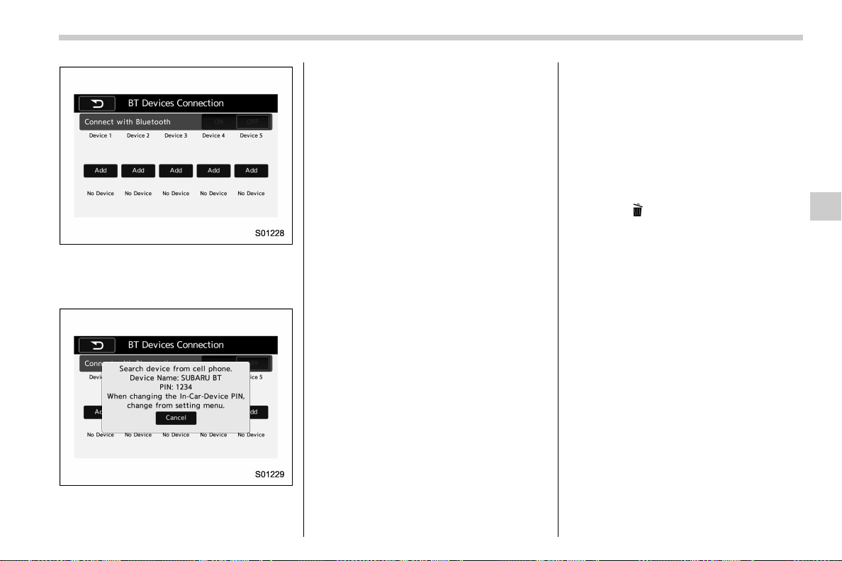
(309,1)
北米Model "A1700BE-B" EDITED: 2017/ 10/ 11
“BT Devices Connection” screen (At the
initial startup a nd w hen no device is
registered).
5. Touch the “Add” key.
When the “Add” key is selected (Waiting
for the connection request from a device).
. For details about operating the Blue-
tooth device, see the manual that
comes with it.
. To cancel the registration, touch the
“Cancel” key.
6. Register the Bluetooth device using
your Bluetooth device.
. A PIN-code is not required for SSP
(Secure Simple Pairing) compatible
Bluetooth devices. Depending on the
type of Bluetooth device being con-
nected, a message confirming regis-
tration may be displayed on the Blue-
tooth device’s screen. Respond and
operate the Bluetooth device accord-
ing to the confirmation message.
7. Check that the screen is displayed
when registration is complete.
. The system wai ts for c onnec tion
requests coming from the registered
device.
. At this stage, the Bluetooth functions
are not yet available.
! Registering a Bluetooth Audio de-
vice for the first time
To use the Bluetooth Audio, it is necessary
to register an audio device w ith the
system.
The device registration procedure is the
same for both the hands-free system and
Bluetooth audio.
1. Display the “BT Devices Connection”
screen. Refer to “Registering a Bluetooth
phone for the first time” F5-64.
2. Select the “Add” key.
The “Add” key is not displayed when five
devices are already registered.
To add another device, you need to delete
one of the registered devices.
Press the
key for the device to be
deleted, and then select the “OK” key.
3. Register the Bluetooth device using
your Bluetooth device.
. A PIN-code is not required for SSP
(Secure Simple Pairing) compatible
Bluetooth devices. Depending on the
type of Bluetooth device being con-
nected, a message confirming regis-
tration may be displayed on the Blue-
tooth device’s screen. Respond and
operate the Bluetooth device accord-
ing to the confirmation message.
4. Check that the screen is displayed
when registration is complete.
. The system waits for connection
requests coming from the registered
device.
. At this stage, the Bluetooth functions
are not yet available.
– CONTINUED –
Audio/Bluetooth
®
settings
5-65
5

(310,1)
北米Model "A1700BE-B" EDITED: 2017/ 10/ 11
! Profiles
This system supports the following services.
Bluetooth Device Spec. Function Requirements Recommendations
Bluetooth Phone/Bluetooth
Audio Device
Bluetooth Specification
Registering a Bluetooth de-
vice
Ver. 1.1
Ver. 2.1 + EDR
Bluetooth Device Profile Function Requirements Recommendations
Bluetooth Phone
HFP (Hands-Free Profile) Hands-free system Ver. 1.0 Ver. 1.5
OPP (Object Push Profile)
Transferring the contacts
Ver. 1.1 Ver. 1.1
PBAP (Phone Book Access
profile)
Ver. 1.0 Ver. 1.0
MAP (Message Access
Profile)
Bluetooth phone message — Ver. 1.0
SPP (Serial Port Profile)
Connecting a Bluetooth
phone
— Ver. 1.1
Bluetooth Audio Device
A2DP (Advanced Audio
Distribution Profile)
Bluetooth audio system
Ver. 1.0 Ver. 1.2
AVRCP (Audio/Video Re-
mote Control Profile)
Ver. 1.0
Ver. 1.4
NOTE
. If your cell phone does not support HFP, registering the Bluetooth phone or using OPP, PBAP, MAP or SPP profiles
individually will not be possible.
. If the connected Bluetooth device version is older than recommended or incompatible, the Bluetooth device function may
not work properly.
. For USA customers, please visit www.subaru.com for details. Outside of the USA customers, contact your local dealer to
arrange a demonstration in order to confirm whether or not the device can be paired with the vehicle.
Audio/Bluetooth
®
settings
5-66
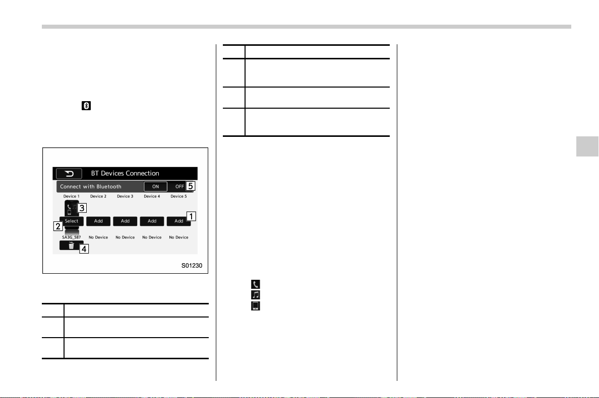
(311,1)
北米Model "A1700BE-B" EDITED: 2017/ 10/ 11
& Setting Bluetooth details
! BT Devices Connection screen
1. Press the HOME button.
2. Touch the “SETTINGS” key and then
touch the
tab.
3. Touch the “BT Devices Connection”
key and then select the desired device to
register.
“BT Devices Connection” screen (One
device is registered.)
No. Function
&
1
Register the device. Refer to “Register-
ing/connecting Bluetooth
®
device” F5-64.
&
2
Make the connection to the registered
device.
No. Function
&
3
This shows the status of the device
connection profile. (The icon illuminates
while connected.)
&
4
Delete the registered device. Refer to
“
Deleting a Bluetooth device” F5-68.
&
5
Switch to connect/disconnect Bluetooth
communication. Refer to “
Bluetooth ON/
OFF” F5-67.
! Connecting a Bluetooth device
Up to 5 Bluetooth devices (phones and
audio devices) can be registered.
If more than 1 Bluetooth device has been
registered, select which device to connect
to.
1. Display the “BT Devices Connection”
screen. Refer to “BT Devices Connection
screen” F5-67.
2. Select the device to be connected.
. Supported profile icons will be dis-
played.
–
: Phone
–
: Audio device
–
: Smartphone Application
. Supported profile icons for currently
connected devices will illuminate.
. The audio icon illuminates only when
in the Bluetooth audio mode.
. All icons are dimmed when Blue-
tooth is set to off or when the connec-
tion cannot be made with the device.
NOTE
. It may take time if the device con-
nection is carried out during Bluetooth
audio playback.
. Depending on the type of Bluetooth
device being connected, it may be
necessary to perform additional steps
on the device.
. It is not possible to establish a
Bluetooth connection with iOS devices
currently connected with a USB cable.
. Supported profile icons of the un-
selected devices are not displayed if
several Bluetooth devices have been
registered.
! Bluetooth ON/OFF
1. Display the “BT Devices Connection”
screen. Refer to “BT Devices Connection
screen” F5-67.
2. Select the “ON” or “OFF” key by the
right side of the “Connect with Bluetooth”
key. The “ON” key establishes a connec-
tion, and the “OFF” key disconnects the
connection.
– CONTINUED –
Audio/Bluetooth
®
settings
5-67
5
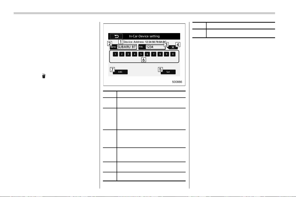
(312,1)
北米Model "A1700BE-B" EDITED: 2017/ 10/ 11
NOTE
The setting is fixed as the “OFF” key
when no device is registered.
! Deleting a Bluetooth device
1. Display the “BT Devices Connection”
screen. Refer to “BT Devices Connection
screen” F5-67.
2. Select the desired device.
3. Touch the
key for the device to be
deleted, and then select the “OK” key.
NOTE
When deleting a Bluetooth phone, the
contact data will be deleted at the same
time.
! “In-Car-Device setting” screen
The Bluetooth settings can be confirmed
and changed.
1. Display the “SETTINGS” screen. Refer
to “Registering a Bluetooth phone for the
first time” F5-64.
2. On the “SETTINGS” screen for “In-
Car-Device setting”, select the “Set” key.
No. Function
&
1
Display the Bluetooth device address
of the in-vehicle equipment.
&
2
Display the Bluetooth device name of
the in-vehicle equipment. The default
name is “SUBARU BT”, which can be
changed by selecting it and entering
alphanumeric characters.
&
3
Display the PIN code of the in-vehicle
equipment. The default code is
“1234”, which can be changed by
selecting it and entering numbers.
&
4
Delete one character from the cur-
rently selected item (BT device name
or the PIN code).
&
5
Save the current BT device name and
PIN code.
&
6
Numeric input keys.
No. Function
&
7
Switch the screen to input characters.
! Editing the Bluetooth device
name
The device name can be set or changed.
1. Touch the “Name” key.
2. Enter a name and then select the “Set”
key.
! Editing the PIN-Code
The PIN-code can be set or changed.
1. Select the “PIN” Key.
2. Enter a PIN-code and then select the
“Set” key.
NOTE
If the “PIN” key is already selected, the
“ABC” key is cross-hatched and dis-
abled.
Audio/Bluetooth
®
settings
5-68
(313,1)
北米Model "A1700BE-B" EDITED: 2017/ 10/ 11
Hands-free phone system
The hands-free system enables calls to be
made and received without having to take
your hands off the steering wheel.
This system supports Bluetooth. Bluetooth
is a wireless data system that enables cell
phones to be used without being con-
nected by a cable or placed in a cradle.
The operating procedure of the phone is
explained here.
WARNING
. While driving, do not use a cell
phone or connect the Bluetooth
phone. Doing so may result in
loss of control of your vehicle
and cause an accident or serious
injury.
. Your aud io unit is fitted with
Bluetooth antennas. People with
implantable cardiac pacemakers,
cardiac resynchronization ther-
apy-pacemakers or implantable
cardioverter defibrillators should
maintain a reasonable distance
between themselves and the
Bluetooth antennas. The radio
waves may affect the operation
of such devices.
. Before using Bluetooth devices,
users of any electrical medical
device other than implantable
cardiac pacemakers, cardiac re-
synchronization therapy-pace-
makers or implantable cardiover-
ter defibrillators should consult
the manufacturer of the device
for information about its opera-
tion under the influence of radio
waves. Radio waves could have
unexpected effects on the opera-
tion of such medical devices.
CAUTION
Do not leave your cell phone in the
vehicle. The temperature inside may
rise to a level that could damage the
phone.
NOTE
. If your cell phone does not support
Bluetooth, this system cannot function.
. In the following conditions, the sys-
tem may not function:
– The cell phone is turned off.
– The current position is outside
the communication area.
– The cell phone is not connected.
– The cell phone has a low battery.
. When using the hands free function
and other Bluetooth functions at the
same time, the following problems may
occur:
– The Bluetooth connection may
be cut.
– Noise may be heard when playing
back voice with the Bluetooth func-
tion.
. The other party’s voice will be heard
from the front speakers. The audio/
visual system will be muted during
phone calls or when hands-free voice
commands are used.
. Talk alternately with the other party
on the phone. If both parties speak at
the same time, the other party may not
hear what has been said. (This is not a
malfunction.)
. Keep call volume down. Otherwise,
the other party’s voice may be audible
outside the vehicle and voice echo may
increase. When talking on the phone,
speak clearly towards the microphone.
. The other party may not hear you
clearly when:
– Driving on an unpaved road.
(Making excessive traffic noise.)
– Driving at high speeds.
– The moonroof or windows are
open.
– The air cond itioning vents are
– CONTINUED –
Audio/Hands-free phone system
5-69
5
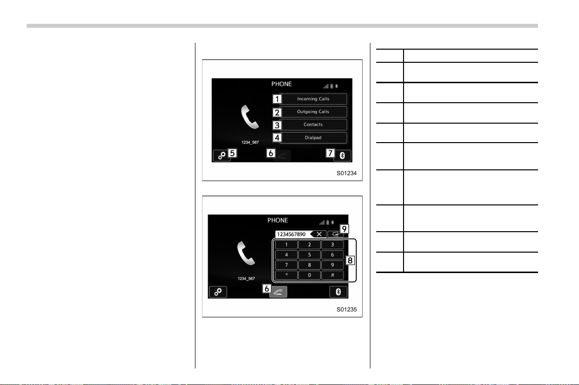
(314,1)
北米Model "A1700BE-B" EDITED: 2017/ 10/ 11
pointed towards the microphone.
– The sound of the air conditioning
fan is loud.
– There is a negative effect on
sound quality due to the phone
and/or network being used.
. When another phone is connected,
the following registered data cannot be
read:
– Contact data
– Call history data
– All phone settings
. When selling or disposing of the
vehicle, initialize the data. Refer to
“Unit settings” F5-18.
. Once initialized, the data and set-
tings will be erased. Take extra caution
when initializing the data.
. The voice command system sup-
ports phone commands, so dialing a
phone number using you r voice is
possible. Refer to “Voice command
system” F5-79.
. The images shown in this Owner’s
Manual are sample images. The actual
images may vary depending on the
market and specifications of your ve-
hicle.
& Control screen
PHONE (Menu) screen
PHONE (Dialpad) screen
No. Function
&
1
Open the “Incoming Calls” screen.
Refer to “
By incoming calls” F5-72.
&
2
Open the “Outgoing Calls” screen.
Refer to “
By outgoing calls” F5-73.
&
3
Open the “Contacts” screen. Refer to
“
By contacts list” F5-73.
&
4
Open the dialpad screen. Refer to “By
Dialpad” F5-74.
&
5
Open the phone volume settings
screen. Refer to “
Phone volume set-
tings” F5-77.
&
6
Use to make a phone call. You cannot
press this key until you open the
dialpad screen and enter a phone
number.
&
7
Open the “BT Devices Connection”
screen. Refer to “
Setting Bluetooth
details” F5-67.
&
8
Enter the phone number that you want
to call.
&
9
Switch the screen to the phone (menu)
screen.
NOTE
When the cell phone is not registered
and the Bluetooth setting is off, a
message is displayed instead of menu
items.
Audio/Hands-free phone system
5-70
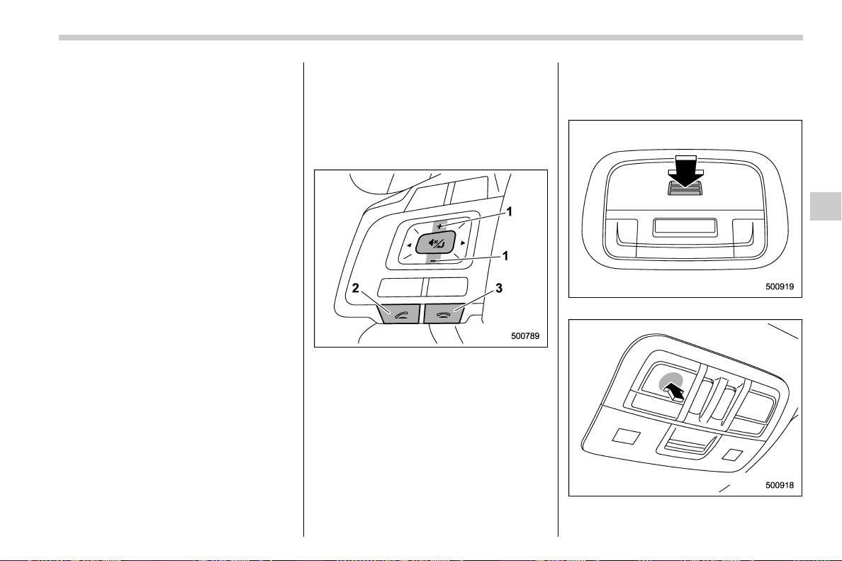
(315,1)
北米Model "A1700BE-B" EDITED: 2017/ 10/ 11
& Registering/connecting a
Bluetooth phone
To use the hands-free system for cell
phones, it is necessary to register a cell
phone with the system. Refer to “Register-
ing/connecting Bluetooth
®
device” F5-64.
! Bluetooth phone condition display
The condition of the Bluetooth phone
appears on the upper right side of the
screen.
& Using the phone switch/mi-
crophone
. Steering switch
By pressing the steering switch, a call can
be received or ended without taking your
hands off the steering wheel.
1) Volume control switch
2) Off hook switch
3) On hook switch
. Microphone
The microphone is used when talking on
the phone.
Type A
Type B
– CONTINUED –
Audio/Hands-free phone system
5-71
5
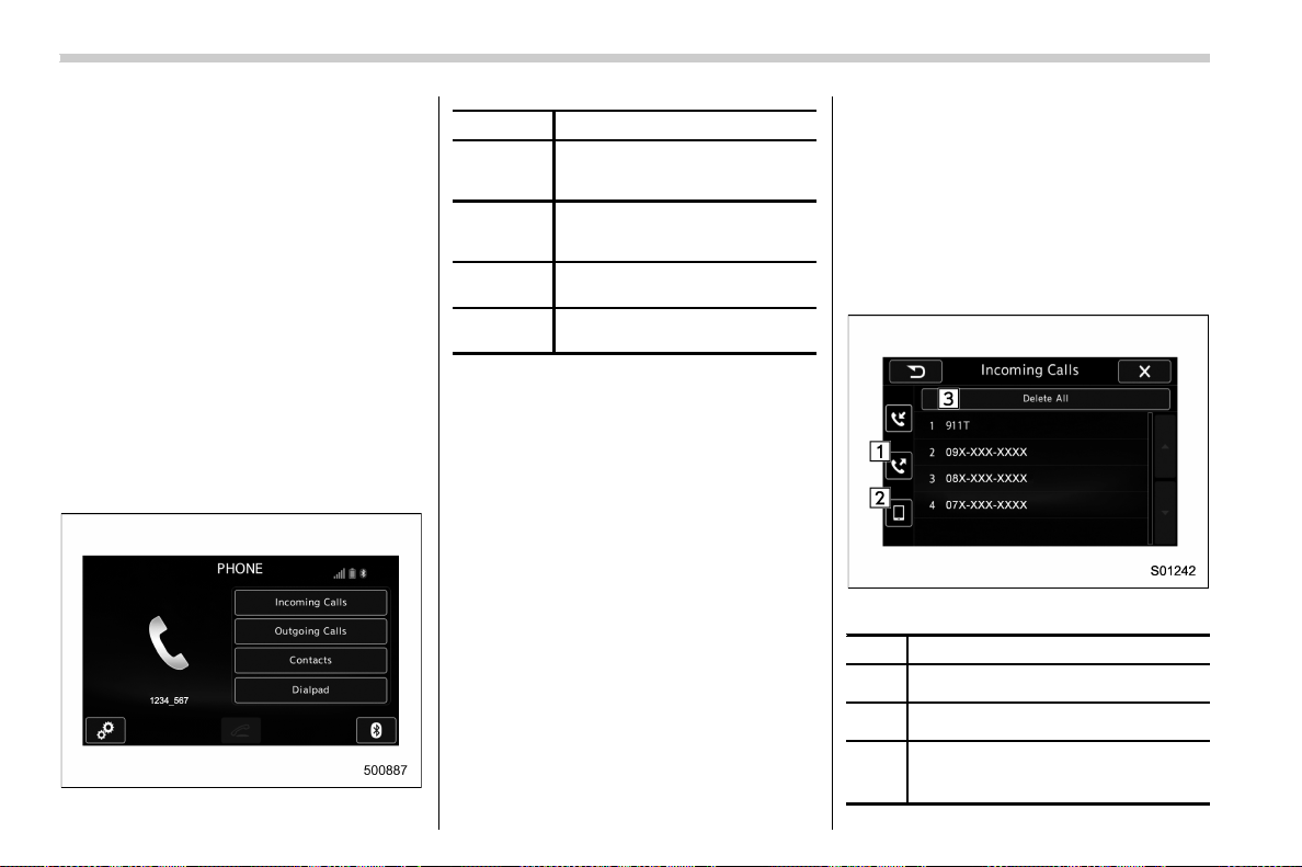
(316,1)
北米Model "A1700BE-B" EDITED: 2017/ 10/ 11
& How to change the hands-free
phone system
The phone (menu) screen can be used to
make a phone call. To display the hands-
free operation screen, press the HOME
button and then select the “PHONE” key,
or press the off hook switch on the steering
wheel.
& Making a call
There are several methods by which a call
can be made, as described below.
1. Press the HOME button on the audio
panel.
2. Touch the “PHONE” key.
3. Select the desired key to make a call
from the list.
Item Function
Incoming
Calls
Display the history of incoming
calls. Refer to “
By incoming calls”
F5-72.
Outgoing
Calls
Display the history of outgoing
calls. Refer to “
By outgoing calls”
F5-73.
Contacts
Display the phonebook. Refer to
“
By contacts list” F5-73.
Dialpad
Dial a phone number. Refer to
“
By Dialpad” F5-74.
NOTE
You can also make a call by using the
following functions.
. Make a call using the off hook switch
on the steering wheel. Refer to “By off
hook switch” F5-75.
. Make a call using voice operation.
Refer to “Voice command system” F5-
79.
! By incoming calls
On the phone (menu) screen, select the
“Incoming Calls” key to open the “Incoming
Calls” screen.
You can make a call by selecting an item in
the incoming call history list.
If there is no incoming call history, a
message appears to indicate that there is
no incoming call history data.
Incoming Calls screen
No. Function
&
1
Open the “Outgoing Calls” screen.
&
2
Open the “Contacts” screen.
&
3
Delete all incoming call history data.
The “Delete All” key is disabled when
there is no incoming call history.
Audio/Hands-free phone system
5-72
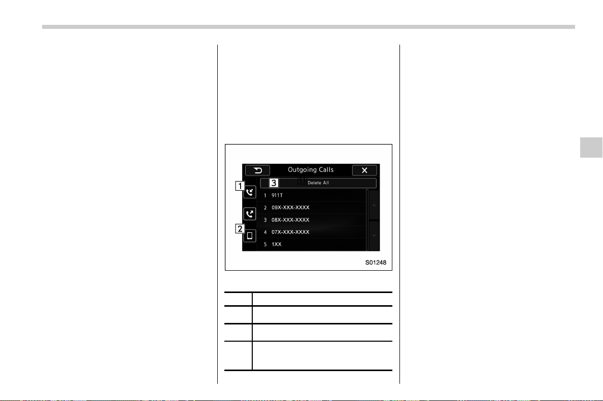
(317,1)
北米Model "A1700BE-B" EDITED: 2017/ 10/ 11
When you select an item in the history list
on the “Incoming Calls” screen, the out-
going call screen opens.
NOTE
. Up to 10 items in the incoming call
history are listed. Scroll the screen to
see items that are not on the screen.
. When making a call to the same
number continuously, only the most
recent call is listed in call history.
. When a phone number registered in
the contact list is received, the name is
displayed.
. Number-withheld calls are also
memorized in the system.
. International phone calls may not be
made depending on the type of cell
phone you have.
. The list should group together con-
secutive entries with the same phone
number and same call type.
! By outgoing calls
On the phone (menu) screen, select the
“Outgoing Calls” key to open the “Outgoing
Calls” screen. You can make a call by
selecting an item in the o utgoing call
history list.
If there is no outgoing call history, a
message appears to indicate that there is
no outgoing call history data.
Outgoing Calls screen
No. Function
&
1
Open the “Incoming Calls” screen.
&
2
Open the “Contacts” screen.
&
3
Delete all outgoing call history data.
The “Delete All” key is disabled when
there is no outgoing call history.
When you select an item in the history list
on the “Outgoing Calls” screen, the out-
going call screen opens.
NOTE
. Up to 10 items in the outgoing call
history are listed. Scroll the screen to
see items that are not on the screen.
. When making a call to the same
number continuously, only the most
recent call is listed in call history.
. When a phone number registered in
the contact list is received, the name is
displayed.
. Number-withheld calls are also
memorized in the system.
. International phone calls may not be
made depending on the type of cell
phone you have.
. The list should group together con-
secutive entries with the same phone
number and same call type.
! By contacts list
On the phone (menu) screen, select the
“Contacts” key to open the phone number
list screen.
You can make a call by selecting an item in
the list (up to five phone numbers are
listed).
If there is no contact data, a message is
displayed to indicate that there is no
– CONTINUED –
Audio/Hands-free phone system
5-73
5
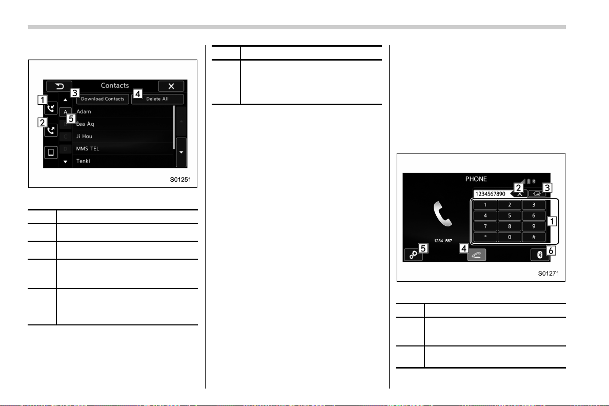
(318,1)
北米Model "A1700BE-B" EDITED: 2017/ 10/ 11
contact data.
Contacts screen
No. Function
&
1
Open the “Incoming Calls” screen.
&
2
Open the “Outgoing Calls” screen.
&
3
Open a pop-up screen for starting the
download of contact data. Refer to
“Update contacts from phone” F5-78.
&
4
Delete all contact data. The “Delete
All” key is disabled when there is no
contact data. Refer to “
Deleting the
contact data” F5-79.
No. Function
&
5
Open a list of contacts that starts with
the selected character. This key is
cross-hatched and cannot be selected
if there is no contact data that starts
with the selected character.
Select the up/down arrow key to scroll the
list of contacts.
When you select a phone number on the
screen, the outgoing call screen opens.
NOTE
Up to 1000 items in the contact data are
listed. Scroll the screen to see items
that are not on the screen.
! When the contact is empty
For PBAP incompatible but OPP com-
patible Bluetooth phones
On the “Co ntacts” screen, sel ect the
“Download Contacts” key. A screen where
you can select how to download contacts
opens.
You can select to download all items or
download one item. For details, refer to
“Update contacts from phone” F5-78.
! Delete contacts
When the “Delete All” key is selected, all
contact data downloaded into the in-
vehicle equipment will be deleted.
Refer to “Deleting the contact data” F5-
79.
! By Dialpad
Input the phone number manually using
the keypad displayed on the screen.
Phone (Dialpad) screen
No. Function
&
1
Allow you to enter numbers from 0 to 9
and *, #, and +. To enter “+”, press and
hold the “0” key.
&
2
Delete one character from the entered
characters.
Audio/Hands-free phone system
5-74
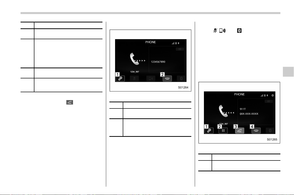
(319,1)
北米Model "A1700BE-B" EDITED: 2017/ 10/ 11
No. Function
&
3
Switch the screen to the phone (menu)
screen.
&
4
Open the “Outgoing Calls” screen and
dials the entered phone number. This
is the same as pressing the off hook
switch on the steering wheel. This key
is cross-hatched and cannot be se-
lected until the phone number is
entered.
&
5
Open the “Options” screen. Refer to
“
Phone volume settings” F5-77.
&
6
Open the “BT Devices Connection”
screen. Refer to “
Setting Bluetooth
details” F5-67.
When you enter a phone number on the
screen and select the
key, the “Out-
going Call” screen opens.
! By off hook switch
Calls can be made using the latest call
history item.
1. Press the off hook switch on the
steering wheel to display th e phone
(menu) screen.
2. Check that the call screen is displayed.
! Outgoing screen
Outgoing call screen
No. Function
&
1
Open the “Options” screen. Refer to
“
Phone volume settings” F5-77.
&
2
Abort the call. The screen returns to
the phone (menu) screen. This is the
same as pressing the on hook switch
on the steering wheel.
NOTE
. Depending on the type of Bluetooth
phone being connected, it may be
necessary to perform additional steps
on the phone.
. When you are on the outgoing call
screen, the screen changes to the call
screen when the other party answers
the call.
. The
, , and keys are disabled
on the outgoing call screen.
& Receiving a call
! Incoming calls
When a call is received, the incoming call
screen is displayed with a sound.
When you receive a phone call while the
cell phone is connected, the screen
changes to the incoming call screen.
Incoming call screen
No. Function
&
1
Open the “Options” screen. Refer to
“
Phone volume settings” F5-77.
– CONTINUED –
Audio/Hands-free phone system
5-75
5
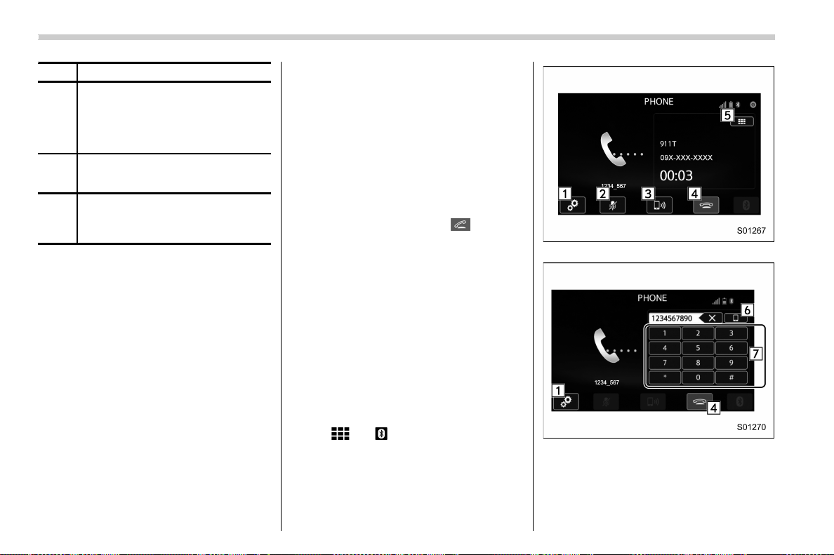
(320,1)
北米Model "A1700BE-B" EDITED: 2017/ 10/ 11
No. Function
&
2
Put the incoming call on hold. This
function may not work on some cell
phone models. This function is the
same as pressing the on hook switch
on the steering wheel for a short
period of time.
&
3
Open the call screen. This function is
the same as pressing the off hook
switch on the steering wheel.
&
4
Reject the incoming call. This function
is the same as pressing and holding
the on hook switch on the steering
wheel.
NOTE
. During international phone calls, the
other party’s name or number may not
be displayed correctly depending on
the type of cell phone you have.
. The ringtone that has been set in the
phone setting screen sounds when
there is an incoming call. Depending
on the type of Bluetooth phone, both
the system and Bluetooth phone may
sound simultaneously when there is an
incoming call. Refer to “Phone volume
settings” F5-77.
! By off/on hook switch
When you receive a call, you can also
answer it by pressing the off hook switch
on the steering wheel. To end a call, press
the on hook switch.
& Talking on the phone
The call screen opens when you perform
the following operations.
. When you accept a call on the incoming
call screen (by selecting the
key), the
call screen opens.
. When you are on the outgoing call
screen, the screen changes to the call
screen when the other party answers the
call.
While talking on the phone, this screen is
displayed. The operations outlined below
can be performed on this screen.
. When the incoming call screen is
displayed and you accept the call, the
screen changes to the call screen. The
screen stays on the incoming call screen if
you reject the call.
. The
and keys are disabled on the
incoming call screen.
Call screen
Call (Dialpad) screen (DTMF)
Audio/Hands-free phone system
5-76
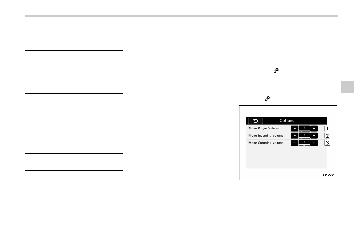
(321,1)
北米Model "A1700BE-B" EDITED: 2017/ 10/ 11
No. Function
&
1
Open the “Options” screen. Refer to
“
Phone volume settings” F5-77.
&
2
Mute your voice to the other party.
Touch this key again to deactivate the
Mute mode. This key is disabled in the
private mode.
&
3
Change the mode to private mode.
The other party’s voice emits from the
cell phone. Touch this key again to
deactivate the private mode.
&
4
End the call. This will return you to the
phone (menu) screen when ending
outgoing calls and the previous screen
when ending incoming calls. This
function is the same as pressing the
on hook switch on the steering wheel.
&
5
Open the call (dialpad) screen. For
details about how to use the function,
refer to “By Dialpad” F5-74.
&
6
Switch the screen to the phone (menu)
screen.
&
7
Allow you to make DTMF (Dual Tone
Multi Frequency) calls. The numbers
you enter are sent as tone signals.
NOTE
. When cell phone call is changed to
hands-free call, the hands-free screen
is displayed and its functions can be
operated on the screen.
. Changing between cell phone call
and hands-free call can be performed
by operating the cell phone directly.
. Transferring methods and opera-
tions will be different depending on
the type of cell phone you have.
. For the operation of the cell phone,
see the manual that comes with it.
. The sound quality of the voice heard
from the other party’s speaker may be
negatively impacted.
& Phone settings
You can transfer the phonebook informa-
tion and adjust the volume of your phone
using the Bluetooth phone system.
NOTE
. The ringer volume for outgoing and
incoming calls, as well as the volume
while on hold or during a call are
controlled independently from the vo-
lume of the audio source. The volume
setting in the phone setting is applied.
. When making a call, receiving a call
or while talking on the phone, you can
adjust the volume by using the power/
Volume knob on the audio panel or the
volume control switch on the steering
wheel.
! Phone volume settings
The ca ll and ringtone volu me can be
adjusted. A ringtone can be selected.
1. Display the “PHONE” screen. Refer to
“How to change the hands-free phone
system” F5-72.
2. Touch the
key.
3. Select the desired item to be set.
. On the “PHONE” screen, the screen
changes to the “Options” screen when you
select the
key.
Options (volume settings) screen
– CONTINUED –
Audio/Hands-free phone system
5-77
5
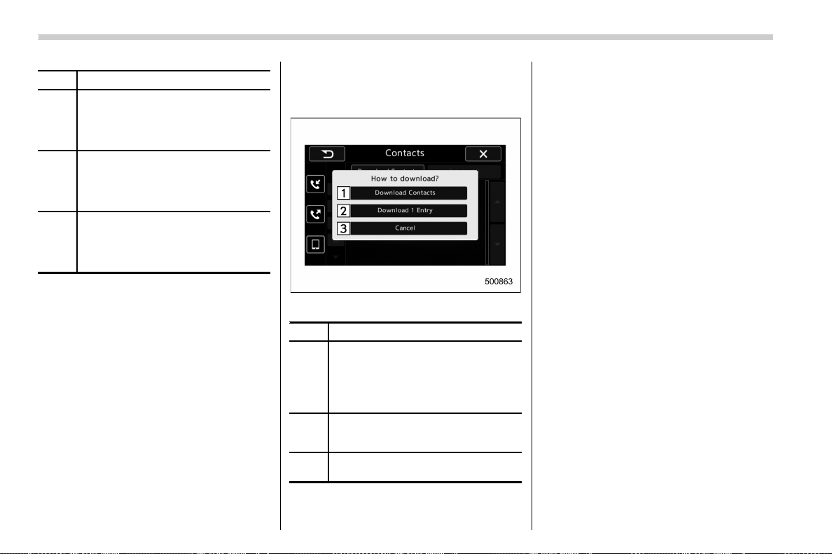
(322,1)
北米Model "A1700BE-B" EDITED: 2017/ 10/ 11
No. Function
&
1
Adjust the ringtone volume. The “−”
key lowers the volume, and the “+” key
increases the volume. (Default vo-
lume: 4 out of a total of 16 volume
levels)
&
2
Adjust the receive volume. The “−” key
lowers the volume, and the “+” key
increases the volume. (Default vo-
lume: 4 out of a total of 16 volume
levels)
&
3
Adjust the transmit volume. The “−”
key lowers the volume, and the “+” key
increases the volume. (Default vo-
lume: 3 out of a total of 5 volume
levels)
NOTE
. Depending on the type of phone,
certain functions may not be available.
. Contact data is managed indepen-
dently for every registered pho ne.
When one phone is connected, another
phone’s registered data cannot be read.
! Update contacts from phone
Operation methods differ between PBAP
(Phone Book Access Profile) compatible
and PBAP incompatible but OPP (Object
Push Profile) compatible Bluetooth
phones.
1. Display the “PHONE” screen. Refer to
“How to change the hands-free phone
system” F5-72.
2. Touch the “Contacts” key, and then
select the “Download Contacts” key.
Contacts screen (Download selection)
No. Function
&
1
Open the download confirmation
screen. Confirm whether or not to
download. If the downloaded contact
(s) already
exist(s), confirm whether or not to
overwrite the existing data.
&
2
Download one set of contact data. To
download the data, you need to
operate from the connected device.
&
3
Cancel the download. The screen
returns to the “Contacts” screen.
NOTE
. If your cell phone is neither PBAP
nor OPP compatible, the contacts can-
not be transferred.
. When you are transferring the con-
tacts data, you may have to operate the
cell phone, depending on the type of
cell phone.
. Depending on the type of cell phone,
some functions may not be supported.
! For PBAP compatible Bluetooth
phones
1. Select the “Download Contacts” or
“Download 1 Entry” key. Contacts are
transferred automatically.
2. Check that a confirmation screen is
displayed when the operation is complete.
. This operation may be unnecessary
depending on the type of cell phone.
. If another Bluetooth device is con-
nected when transferring contact data,
depending on the phone, the con-
nected Bluetooth device may need to
be disconnected.
Audio/Hands-free phone system
5-78
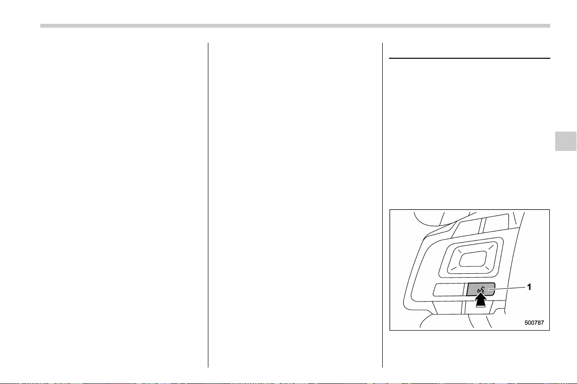
(323,1)
北米Model "A1700BE-B" EDITED: 2017/ 10/ 11
! For PBAP incompatible but OPP
compatible Bluetooth phones
1. Select the “Download 1 Entry” key.
2. Transfer the contact data to the system
using a Bluetooth phone.
. This operation may be unnecessary
depending on the type of cell phone.
. To cancel this function, select the
“Cancel” key.
3. Check that a confirmation screen is
displayed when the operation is complete.
NOTE
To download all items, you may need to
change the settings in your cell phone
beforehand.
! Deleting the contact data
You can delete the phonebook data stored
in the audio set.
1. Display the “PHONE” screen. Refer to
“How to change the hands-free phone
system” F5-72.
2. Touch the “Contacts” key, and then
select the “Delete All” key.
3. Select the “OK” key when the con-
firmation screen appears.
NOTE
. Manual transfer operation cannot be
performed while driving.
. If your cell phone is neither PBAP
nor OPP compatible, the contacts can-
not be transferred.
. Depending on the type of Bluetooth
phone:
– It may be necessary to perform
additional steps on the phone when
transferring contact data.
Voice command system
The voice command system enables the
audio, hands-free phone system, etc. to be
operated using voice commands.
Refer to the “Command list” F5-83 for
samples of voice commands.
Voice commands can be used even when
you set the system to another language.
For details about setting language, refer to
“General settings” F5-19.
& Using the voice command
system
! Steering switch
1) Talk switch
– CONTINUED –
Audio/Voice command system
5-79
5
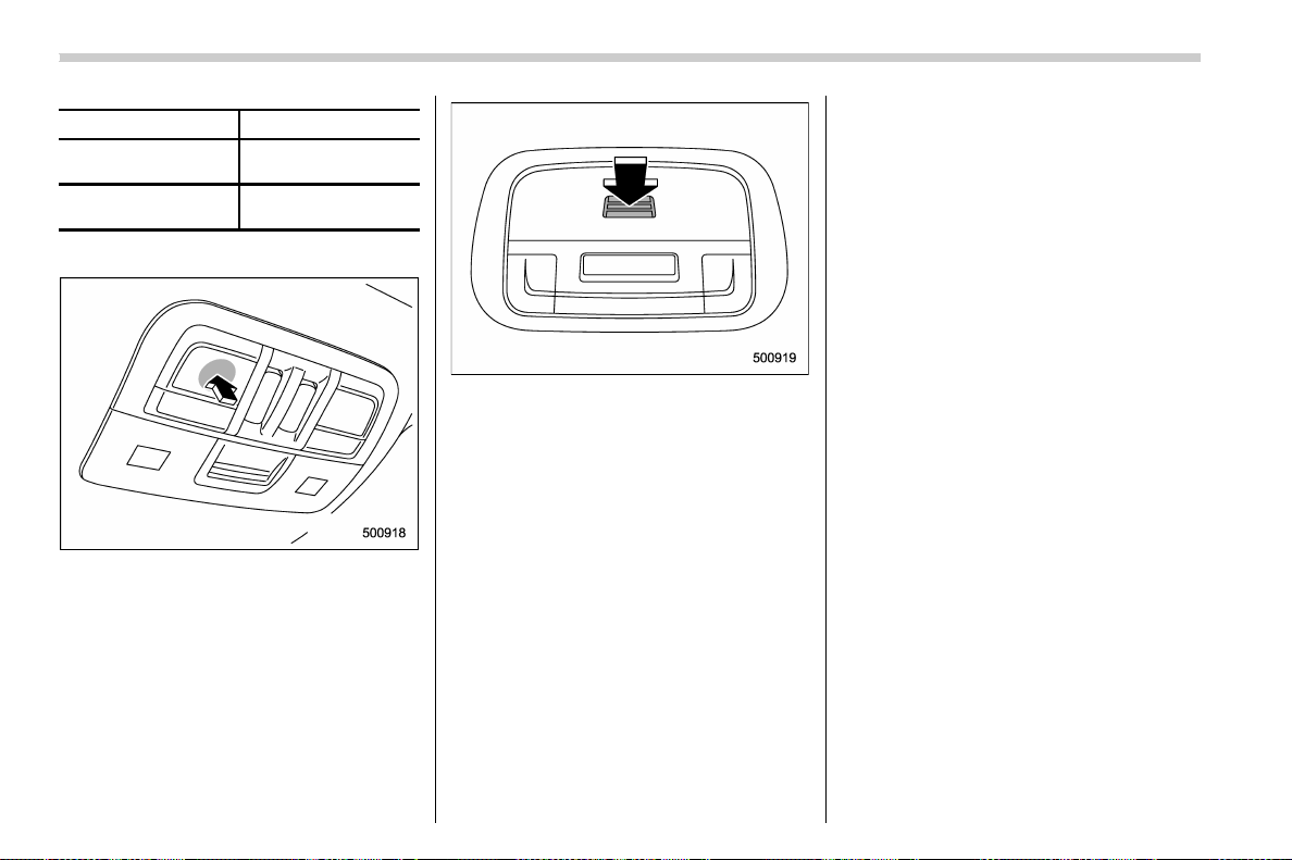
(324,1)
北米Model "A1700BE-B" EDITED: 2017/ 10/ 11
Action Function
Press
Start the voice com-
mand system.
Press and hold
Cancel voice recogni-
tion.
! Microphone
Type A
Type B
It is unnecessary to speak directly into the
microphone when giving a command.
NOTE
. Wait for the confirmation beep be-
fore speaking a command.
. Voice commands may not be recog-
nized if:
– Spoken too quickly.
– Spoken at a low or high volume.
– The moonroof or windows are
open.
– Pa ssengers are talki ng while
voice commands are spoken.
– The air conditioning speed is set
high.
– The air conditioning vents are
turned towards the microphone.
. In the following conditions, the sys-
tem may not recognize the command
properly and using voice commands
may not be possible:
– The command is incorrect or
unclear. Note that certain words,
accents or speech patterns may be
difficult for the system to recognize.
– There is excessive background
noise, such as wind noise.
Audio/Voice command system
5-80
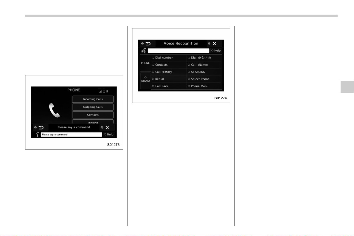
(325,1)
北米Model "A1700BE-B" EDITED: 2017/ 10/ 11
& Voice command system op-
eration
1. Press the talk switch on the steering
wheel.
After the voice command top screen has
been displayed, speech guidance will
commence.
NOTE
When the voice command mode is
audio mode, voice guidance for the
voice command system can be skipped
by pressing th e talk switch o n the
steering wheel.
2. Say the command.
Example (Say “PHONE”)
NOTE
. Commands related with each func-
tion are displayed on the screen of the
each function tab. Some commonly
used commands are displayed on the
screen of the main tab. Even if any tab
is selected, all commands can be
operated.
. Saying
“Help”
prompts guidance to
offer examples of commands and op-
eration methods.
. To cancel voice recognition, select
“6”, or press and hold the talk switch
on the steering wheel.
. If the system does not respond or
the confirmation screen does not dis-
appear, press the talk switch on the
steering wheel and try again.
. The notations used in the com-
mands are as follows.
– < >: Numbers, titles or names to
be spoken
! Voice command example: Call name
1. Press the talk switch on the steering
wheel.
2. Say
“Call <contacts>”
.
. A confirmation screen will be dis-
played showing the recognition results.
If multiple matching items are found, a
selection screen will be displayed. Say
“<number>”
or select the number.
NOTE
. In the same manner as it is displayed
on the screen, “Call <contacts>”, after
saying
“Call a contact”
say the name of
a contact. For example:
“Call a con-
tact”
,
“John Smith”
or
“Call a contact”
,
“Mary Davis”
. Short or abbreviated names in the
contacts list may not be recognized.
Change names in the contacts list to
full names.
. Sometimes a voice recognition re-
sult confirmation screen will be dis-
played. After confirming the result, say
“Yes”
or
“No”
.
. When the system recognizes multi-
– CONTINUED –
Audio/Voice command system
5-81
5
(326,1)
北米Model "A1700BE-B" EDITED: 2017/ 10/ 11
ple names from the contacts list, a
name candidate list will be displayed
on the screen. If the desired name is not
displayed on the top of the screen, say
or select the number of the name from
the candidate list (number 1, number 2,
etc.) to select a name from the candi-
date list.
. When a contact has multiple phone
numbers registered in the contacts list,
a candidate list will be displayed. If the
desired phone number is not displayed
on the top of the screen, say or select
the number of the desired phone num-
ber from the candidate list (number 1,
number 2, etc.) to select a phone
number from the candidate list.
! Voice command example: Dial
number
1. Press the talk switch on the steering
wheel.
2. Say
“Dial number”
.
3. Say
“Dial <number>”
.
For example, if the phone number is
2345678:
Say
“two three four five six seven eight”
Do not say
“twenty three forty five sixty
seven eight”
4. Say
“Dial”
or press the off hook switch
on the steering wheel.
NOTE
. When the system recognizes multi-
ple phone numbers, a phone number
candidate list will be displayed on the
screen. Pressing the off hook switch on
the steering wheel makes a call to the
top entry on the list. If the desired
phone number is not displayed on the
top of the screen, say the number of the
desired phone number from the candi-
date list to select a phone number from
the candidate list.
. Calling to the following phone num-
bers
– 3 digit numbers (911, 411, 611)
– 7 digit numbers (Local phone
numbers)
– 10 digit numbers (Area code +
Local phone number)
– 11 digit phone numbers (1 + Area
code + Local phone number)
. As the system cannot recognize
additional numbers, say the complete
number without stopping.
! Casual speech recognization
Due to natural language speech recogni-
tion technology, this system enables re-
cognition of a command when spoken
naturally. However, the system cannot
recognize every variation of each com-
mand. In some situations, it is possible to
omit the command for the procedure and
directly state the desired operation. Not all
voice commands are displayed in the
function menu.
NOTE
If the command cannot be recognized
completely, the command input screen
will be displayed. (Search results will
be shown based on the part of the
command that was recognized.)
! Expression examples for each
function
Command Expression examples
“Dial <phone num-
ber>”
Phone <phone num-
ber>.
Audio/Voice command system
5-82
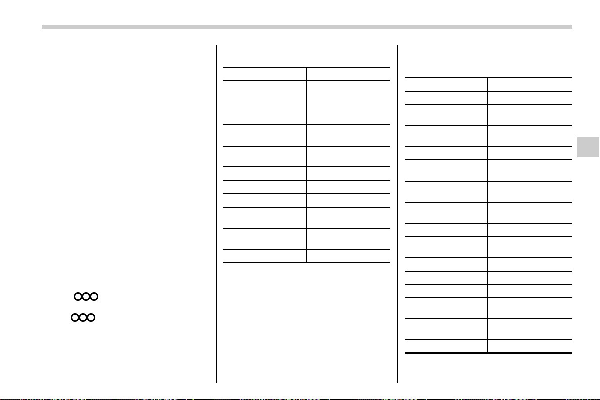
(327,1)
北米Model "A1700BE-B" EDITED: 2017/ 10/ 11
& Command list
Recognizable voice commands and their
actions are shown below.
NOTE
. Some voice commands may not be
available depending on the market,
vehicle specifications or the device
connection status.
. Frequently used commands are
listed in the following tables.
. For devices that are not installed in
the vehicle, the related commands will
not be displayed on the screen. Also,
according to conditions, other com-
mands may not be displayed on the
screen.
. The functions available may vary
according to the system installed.
. Voice recognition language can be
changed. Refer to “Unit settings” F5-
18.
. The notations used in the com-
mands are as follows.
– <
>: Numbers, titles or
names to be spoken
– (
):Thereisnoneedto
speak the command, the voice
command system will recognize
the content.
! Basic command
Voice command Function
Back
Go back one hierar-
chy or cancel the
voice recognition
(voice command top
screen)
Help
Ask for help with the
current task
Cancel, Close
Cancel the current
task
Yes
No
Display OFF Turns the display off
Audio ON
Turns the audio sys-
tem on
Audio OFF
Turns the audio sys-
tem off
STARLINK
Switch to APPS mode
! Commands for changing the audio
mode
Voice command Function
Change to AM Switch to AM mode
Change to AM1
Switch to AM mode
band 1
Change to AM2
Switch to AM mode
band 2
Change to FM Switch to FM mode
Change to FM1
Switch to FM mode
band 1
Change to FM2
Switch to FM mode
band 2
Change to FM3
Switch to FM mode
band 3
Change to SiriusXM Switch to XM mode
Change to BT Audio
Switch to Bluetooth
Audio mode
Change to CD Switch to CD mode
Change to USB Switch to USB mode
Change to iPod Switch to iPod mode
Change to aha
Switch to aha radio
mode
Change to Pandora
Switch to Pandora
mode
Change to AUX
Switch to AUX mode
– CONTINUED –
Audio/Voice command system
5-83
5
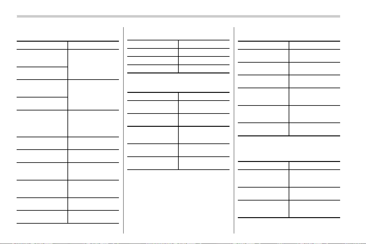
(328,1)
北米Model "A1700BE-B" EDITED: 2017/ 10/ 11
! Commands for hands-free phone
Voice command Function
Dial Number ? <0-9,
+, *, #> ? Change
number, Dial
Places a call to the
said phone number
Dial <0-9, +, *, #> ?
Change number, Dial
Contacts, Phonebook
? <Name> ? <1-5>
? Dial
Make a call by using
the phonebook
Call <Name> ?
<1-5> ? Dial
Call History ? In-
coming call, Outgoing
call ? Next (page),
Previous (page) ?
<1-5> ? Dial
Make a call by using
the call history
Incoming Calls
Display the call history
screen
Outgoing Calls
Display the call history
screen
Redial
Places a call to the
phone number of the
latest outgoing call
Callback
Places a call to the
phone number of the
latest incoming call
Select Phone ?
<1-5>
Display the phone se-
lect screen
Phone Menu
Display the hands free
top screen
! Commands for Pandora
Voice command Function
Like Mark “Like” flag
Dislike Mark “Dislike” flag
Skip, Next
Skip to the next song
! Commands for aha
Voice command Function
Thumbs Up, Heart,
Like
Mark “Like” flag
Thumbs Down, Ban,
Dislike
Mark “Dislike” flag
Refresh, update
Refresh the selected
station to get the latest
information
Content Up
Playback next Con-
tent
Content Down
Playback previous
Content
! Commands for AM/FM control
Voice command Function
Seek Up
Tunes in the higher
frequency direction
Seek Down
Tunes in the lower
frequency direction
Scan
Switch to the scan
mode
Tune to <Frequency>
Designate the fre-
quency to switch to a
specific radio station
Preset <preset num-
ber>
Designate the preset
channel to switch to
specific radio station
Tag
iTunes Tagging for HD
Radio
! Commands for SiriusXM radio con-
trol
Voice command Function
Preset <preset num-
ber>
Designate the preset
channel to switch to
specific radio station
Scan
Switch to the scan
mode
Channel <Channel
number>
Designate the chan-
nel to switch to speci-
fic radio station
Audio/Voice command system
5-84
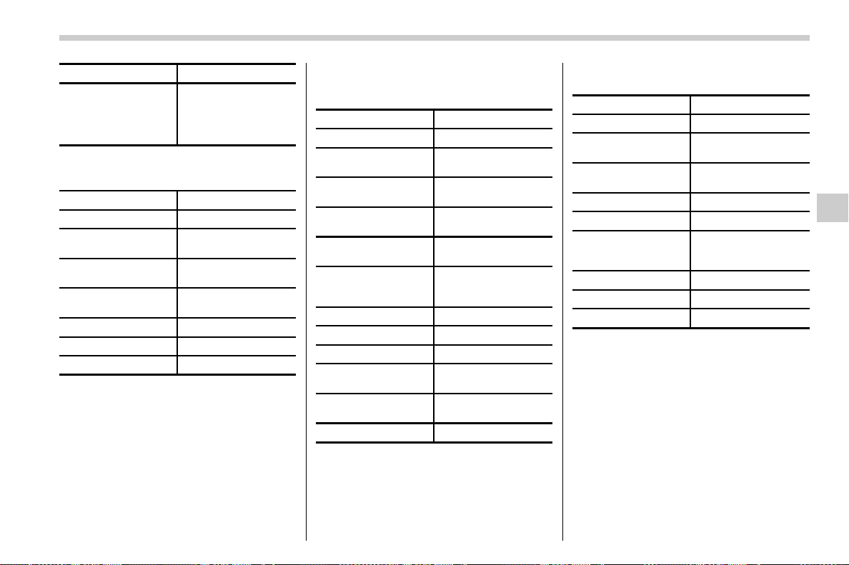
(329,1)
北米Model "A1700BE-B" EDITED: 2017/ 10/ 11
Voice command Function
Category ? Next
(page), Previous
(page), <1-5> ? Next
(page), Previous
(page), <1-5>
Displays the category
list screen
! Commands for CD control
Voice command Function
Track Up Select the next track
Track Down
Select the current
track
Scan
Switch to the scan
mode
Repeat ? 1 Track
Repeat, Repeat All
Select a repeat mode
1 Track Repeat Repeat single track
Repeat All Repeat all tracks
Shuffle
Plays randomly
! Commands for MP3/WMA/AAC,
USB control
Voice command Function
Track Up Select the next track
Track Down
Select the current
track
Folder Up
Plays from the start of
the next folder
Folder Down
Plays from the start of
the previous folder
Scan
Switch to the scan
mode
Repeat ? 1 Track
Repeat, Repeat
Folder, Repeat All
Select a repeat mode
1 Track Repeat Repeat single track
Repeat Folder Repeat of the folder
Repeat All Repeat all tracks
Shuffle ? Shuffle
Folder, Shuffle All
Select a random play
mode
Shuffle Folder
Plays randomly of the
folder
Shuffle All
Plays randomly
! Commands for iPod Control
Voice command Function
Track Up Select the next track
Track Down
Select the current
track
Repeat ? Repeat
One, Repeat All
Select a repeat mode
Repeat One Repeat single track
Repeat All Repeat all tracks
Shuffle ? Shuffle
Track, Shuffle Album,
Shuffle OFF
Select a random play
mode
Shuffle Track Shuffle all tracks
Shuffle Album Shuffle all tracks
Shuffle OFF
Turn off shuffle
– CONTINUED –
Audio/Voice command system
5-85
5

(330,1)
北米Model "A1700BE-B" EDITED: 2017/ 10/ 11
! Commands for Bluetooth audio
control
Voice command Function
Pause Pause play
Track Up Select the next track
Track Down
Select the current
track
Repeat ? 1 track
Repeat, Repeat All,
Group Repeat
Select a repeat mode
1 Track Repeat Repeat single track
Repeat All Repeat all tracks
Group Repeat
Repeat tracks on
group
Shuffle ? Shuffle All,
Group Shuffle, Shuffle
OFF
Select a random play
mode
Shuffle All Shuffle all tracks
Group Shuffle
Shuffle tracks on
group
Shuffle OFF
Turn off shuffle
Audio/Voice command system
5-86
(331,1)
北米Model "A1700BE-B" EDITED: 2017/ 10/ 11
What to do if...
& Troubleshooting
If there is a problem with the hands-free system or a Bluetooth device, first check the table below.
When using the hands-free system with a Bluetooth device
Symptom Likely cause Solution
Page
Cell
phone
This
system
The hands-free system or Bluetooth
device does not work.
The connected device may not be a
compatible Bluetooth cell phone.
For USA customers, please visit
www.subaru.com for details. Outside of the
USA customers, contact your local dealer to
arrange a demonstration in order to confirm
whether or not the device can be paired with
the vehicle.
* —
The Bluetooth version of the connected
cell phone may be older than the
specified version.
Use a cell phone with Bluetooth version 1.1 or
higher (recommended: Ver. 2.1 + EDR or
higher).
*
5-66
*: For details, refer to the owner’s manual that came with the cell phone.
– CONTINUED –
Audio/What to do if...
5-87
5

(332,1)
北米Model "A1700BE-B" EDITED: 2017/ 10/ 11
When registering/connecting a cell phone
Symptom Likely cause Solution
Page
Cell
phone
This
system
A cell phone cannot be registered.
An incorrect passcode was entered on
the cell phone.
Enter the correct passcode on the cell phone. * —
The registration operation has not
been completed on the cell phone
side.
Complete the registration operation on the cell
phone (approve registration on the phone).
* —
Old registration information remains
on either this system or the cell phone.
Delete the existing registration information from
both this system and the cell phone, then register
the cell phone you wish to connect to this system.
*5-67
A Bluetooth connection cannot be
made.
Another Bluetooth device is already
connected.
Manually connect the cell phone you wish to use to
this system.
— 5-67
Bluetooth function is not enabled on
the cell phone.
Enable the Bluetooth function on the cell phone. * —
Automatic Bluetooth connection on
this system is set to off.
Set automatic Bluetooth connection on this system
to on when the ignition switch is turned to the “ACC”
or “ON” position.
—
5-67
*: For details, refer to the owner’s manual that came with the cell phone.
Audio/What to do if...
5-88
(333,1)
北米Model "A1700BE-B" EDITED: 2017/ 10/ 11
When using the phonebook
Symptom Likely cause Solution
Page
Cell
phone
This
system
Phonebook data cannot be trans-
ferred manually.
The profile version of the connected cell
phone may not be compatible with
transferring phonebook data.
For USA customers, please visit
www.subaru.com for details. Outside of the
USA customers, contact your local dealer to
arrange a demonstration in order to confirm
whether or not the device can be paired with
the vehicle.
* —
Transfer operation on the cell phone has
not completed.
Complete transfer operation on the cell phone
(approve transfer operation on the phone).
* —
Phonebook data cannot be edited.
Editing function is not available on this
system.
——
5-77
*: For details, refer to the owner’s manual that came with the cell phone.
– CONTINUED –
Audio/What to do if...
5-89
5
(334,1)
北米Model "A1700BE-B" EDITED: 2017/ 10/ 11
In other situations
Symptom Likely cause Solution
Page
Cell
phone
This
system
Even though all conceivable mea-
sures have been taken, the symptom
status does not change.
The cell phone is not close enough to
this system.
Bring the cell phone closer to this system. ——
The cell phone is the most likely cause of
the symptom.
Turn the cell phone off, remove and reinstall
the battery pack, and then restart the cell
phone.
* —
Enable the cell phone’s Bluetooth connection. * —
Stop the cell phone’s security software and
close all applications.
* —
Before using an application installed on the cell
phone, carefully check its source and how its
operation might affect this system.
*
—
*: For details, refer to the owner’s manual that came with the cell phone.
Audio/What to do if...
5-90
(335,1)
北米Model "A1700BE-B" EDITED: 2017/ 10/ 11
Appendix
& Certification
. Bluetooth
The Bluetooth word mark and logo are
registered trademarks of Bluetooth SIG,
Inc. and any use of such marks by Clarion
Co., Ltd. is under license.
. SiriusXM Satellite Radio (if
equipped)
SiriusXM
TM
and all related marks and
logos are trademarks of SiriusXM Radio
Inc. All rights reserved.
. Pandora (if equipped)
Pandora, the Pandora logo, and other
Pandora marks are trademarks or regis-
tered trademarks of Pandora Media, Inc.,
or its subsidiaries worldwide.
If you have any issues with the Pandora
application on your mobile phone, please
direct them to
. iPod
“Made for iPod” and “Made for iPhone”
mean that an electronic accessory has
been designed to connect specifically to
iPod or iPhone respectively, and has been
certified by the developer to meet Apple
performance standards. Apple is not re-
sponsible for the operation of this device or
its compliance with safety and regulatory
standards. Please note that the use of this
accessory with iPod or iPhone may affect
wireless performance.
iPhone, iPod, iPod classic, iPod nano,
iPod touch, and iTunes are trademarks of
Apple Inc., registered in the U.S. and other
countries.
. How to get the source code using the
open source
This system implements software using
theopensource.Forcustomerswho
would like to get the source code of the
software, it is available by downloading it
from the web site of Clarion Co., Ltd.
For details, refer to the following web site.
http://www.clarion.com/us/en/support/in-
dex.html
& Certification for the Hands-
free system
. U.S.-spec. models
CAUTION
FCC WARNING
Changes or modifications not ex-
pressly approved by the party re-
sponsible for compliance could void
the user’s authority to operate the
equipment.
This device complies with part 15 of the
FCC Rules. Operation is subject to the
following two conditions: (1) This device
may not cause harmful interference, and
(2) this device must accept any interfer-
ence received, including interference that
may cause undesired operation.
– CONTINUED –
Audio/Appendix
5-91
5
(336,1)
北米Model "A1700BE-B" EDITED: 2017/ 10/ 11
. Canada-spec. models
This transmitter must not be co-located or
operated in conjunction with any other
antenna or transmitter.
& Certification for Mexico mod-
els
. IFETEL RCPCLPF14-250
Clarion PF-3547
. IFETEL RCPCLPF14-253
Clarion PF-3688
Audio/Appendix
5-92

(339,1)
北米Model "A1700BE-B" EDITED: 2017/ 10/ 11
Interior lights ........................................................... 6-2
Dome light ............................................................. 6-2
Map lights.............................................................. 6-2
OFF delay timer ..................................................... 6-3
Sun visors ............................................................... 6-3
Sun visor extension plate
(models with the EyeSight system)....................... 6-4
Vanity mirror with light........................................... 6-4
Storage compartment ............................................. 6-5
Glove box .............................................................. 6-5
Center console ...................................................... 6-5
Cup holders............................................................. 6-6
Front passenger’s cup holder................................. 6-6
Rear passenger’s cup holder.................................. 6-7
Bottle holders.......................................................... 6-8
Accessory power outlets........................................6-8
Use with a cigarette lighter (if equipped) ................ 6-9
Ashtray (if equipped)............................................ 6-10
Floor mat (if equipped).......................................... 6-11
Coat hook...............................................................6-11
Under-floor storage compartment....................... 6-12
Rear view camera ................................................. 6-13
How to use the rear view camera .......................... 6-14
Viewing range on the screen ................................. 6-15
Help line...............................................................6-16
Display adjustment ............................................... 6-18
Front View Monitor (if equipped)......................... 6-19
How to access the Front View Monitor .................. 6-19
How to cancel the Front View Monitor................... 6-20
Range of image on screen .................................... 6-20
Guiding line.......................................................... 6-21
Handling of camera .............................................. 6-21
Interior equipment
6
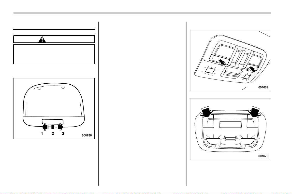
(340,1)
北米Model "A1700BE-B" EDITED: 2017/ 10/ 11
Interior lights
CAUTION
When leaving your vehicle, make
sure the lights are turned off to
avoid battery discharge.
& Dome light
1) ON
2) DOOR
3) OFF
The dome light switch has the following
three positions.
ON: The light remains on continuously.
OFF: The light remains off.
DOOR: The dome light illuminates auto-
matically after any of the following opera-
tions.
. Opening any of the doors.
. Unlocking the doors using the keyless
access function (if equipped). Refer to
“Unlocking” F2-11.
. Unlocking the doors using the remote
keyless entry system. Refer to “Remote
keyless entry system” F2-18.
. Turning the ignition switch from the
“ACC” position to the “LOCK”/“OFF” posi-
tion.
& Map lights
Type A
Type B
To turn on the map light, push the switch.
To turn it off, push the switch again.
Interior equipment/Interior lights
6-2
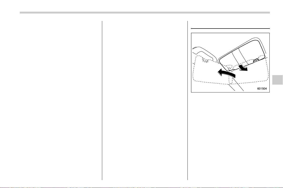
(341,1)
北米Model "A1700BE-B" EDITED: 2017/ 10/ 11
! Automatic illumination (type A map
lights)
The map lights illuminate automatically in
the following cases.
. Any of the doors is opened.
. The doors are unlocked using the
keyless access functi on (if equipped).
Refer to “Unlocking” F2-11.
. The doors are unlocked using the
remote keyless entry transmitter.
. The ignition switch is turned from the
“ACC” position to the “LOCK”/“OFF” posi-
tion.
& OFF delay timer
The following lights have an automatic
illumination function.
. dome light (when the dome light switch
is in the “DOOR” position)
. map light (type A)
After being ill uminated automatically,
these lights remain on for several seconds
and then gradually turn off after all doors
are closed.
While the lights are illuminated, the lights
turn off immediately after any of the
following operations.
. Turning the ignition switch from the
“LOCK”/“OFF” position to the “ACC” or
“ON” position.
. Locking all doors using the keyless
access function (if equipped).
. Locking all doors using the remote
keyless entry system.
The setting for the period of time in which
the lights remain on (OFF delay timer) can
be changed by a SUBARU dealer. Contact
your SUBARU dealer for details. Also, the
setting can be changed by operating the
multi-function disp lay (color L CD). For
details, refer to “Interior light setting” F3-
61.
Sun visors
To block out glare, swing down the visors.
To use the sun visor at a side window,
swing it down and move it sideways.
– CONTINUED –
Interior equipment/Sun visors
6-3
6
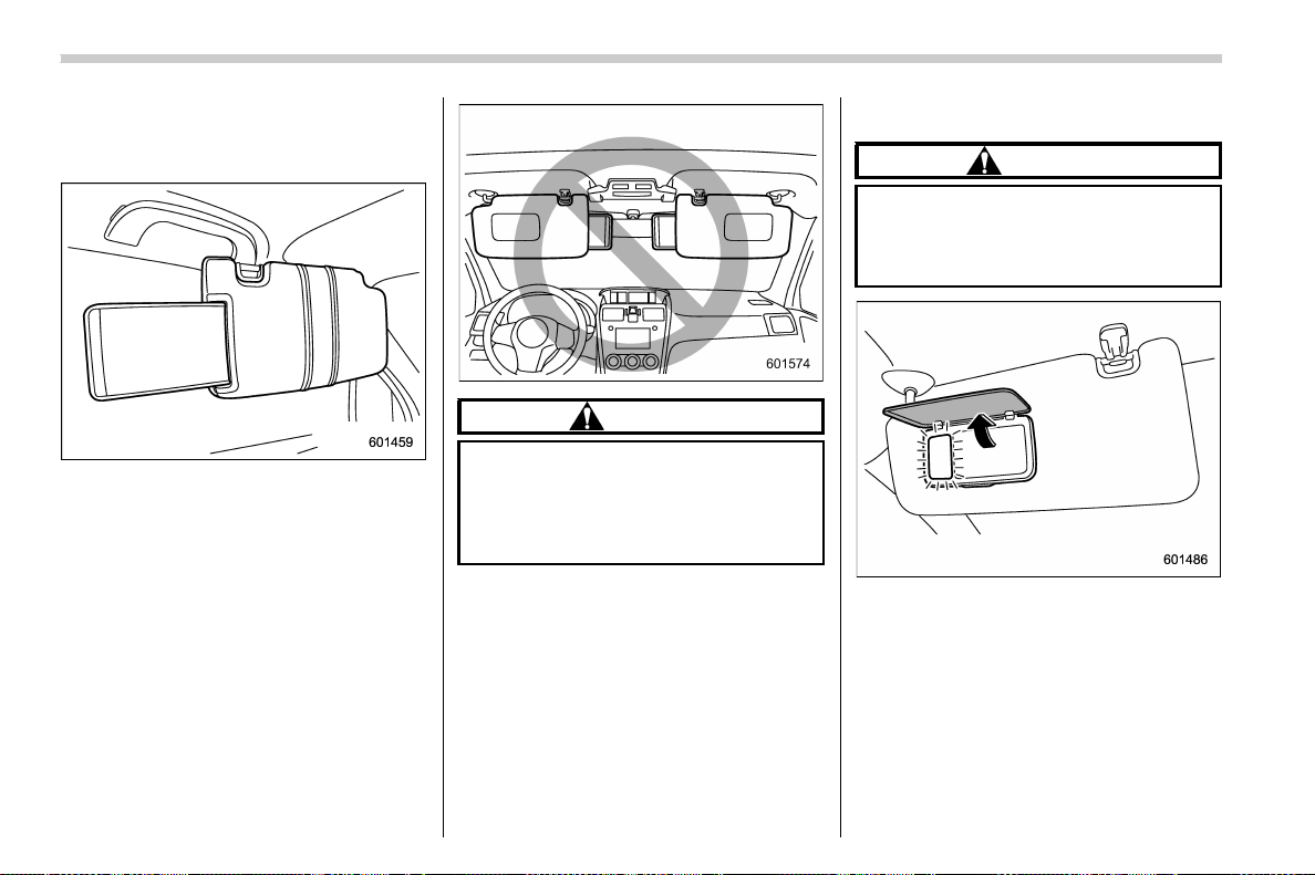
(342,1)
北米Model "A1700BE-B" EDITED: 2017/ 10/ 11
& Sun visor extension plate
(models with the EyeSight
system)
With the sun visor positioned over the side
window, you can use the sun visor exten-
sion plate to prevent glare through the gap
between the sun visor and center pillar. To
use the extension plate, pull it toward the
rear of the vehicle. When you have
finished using it, stow it by pushing it
toward the front of the vehicle.
CAUTION
Do not pull out the extension plate
with the sun visor positioned over
the windshield. The extension plate
would obstruct your view of the rear
view mirror.
& Vanity mirror with light
CAUTION
Keep the vanity mirror cover closed
while the vehicle is being driven to
avoid being temporarily blinded by
the glare of bright light.
To use the vanity mirror, swing down the
sun visor and open the vanity mirror cover.
The light beside the vanity mirror illumi-
nates when the mirror cover is opened.
NOTE
Do not use the vanity mirror light for a
long period of time while the engine is
not running. Doing so can cause bat-
tery discharge.
Interior equipment/Sun visors
6-4
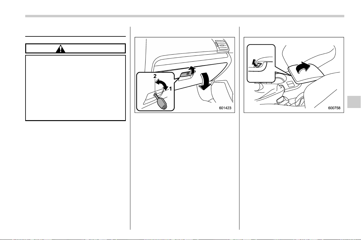
(343,1)
北米Model "A1700BE-B" EDITED: 2017/ 10/ 11
Storage compartment
CAUTION
. Always keep the storage com-
partment closed while driving to
reduce the risk of injury in the
event of a sudden stop or an
accident.
. Do not store spray cans, contain-
ers with flammable or corrosive
liquids or any other dangerous
items in the st orag e compart-
ment.
& Glove box
1) Rotate the key clockwise to lock.
2) Rotate the key counterclockwise to un-
lock.
To open the glove box, pull the handle.
To close it, push the lid firmly upward.
NOTE
. For models with the “keyless access
with push-button start system”, use the
emergency key to lock or unlock the
glove box.
. The emergency key is directional. If
the key cannot be inserted, change the
direction that the grooved side is facing
and insert it again.
& Center console
To open the lid, pull up the lock release.
Interior equipment/Storage compartment
6-5
6
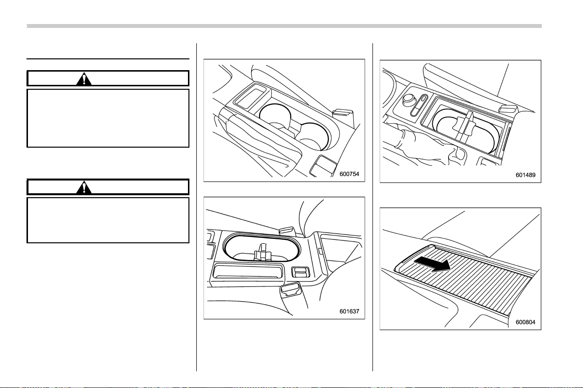
(344,1)
北米Model "A1700BE-B" EDITED: 2017/ 10/ 11
Cup holders
CAUTION
Take care to avoid spills. Beverages,
if hot, might burn you and/or your
passengers. Spilled beverages may
also damage upholstery, carpets or
audio equipment.
& Front passenger’s cup holder
CAUTION
Do not pick up a cup from the cup
holder or put a cup in the holder
while driving. Doing so can distract
you and lead to an accident.
! Except STI
Type A
Type B
A dual cup holder is built into the center
console.
! STI
The dual cup holder is built into the center
console near the parking brake lever.
To access the cup holder, pull the lid
toward the rear.
Interior equipment/Cup holders
6-6
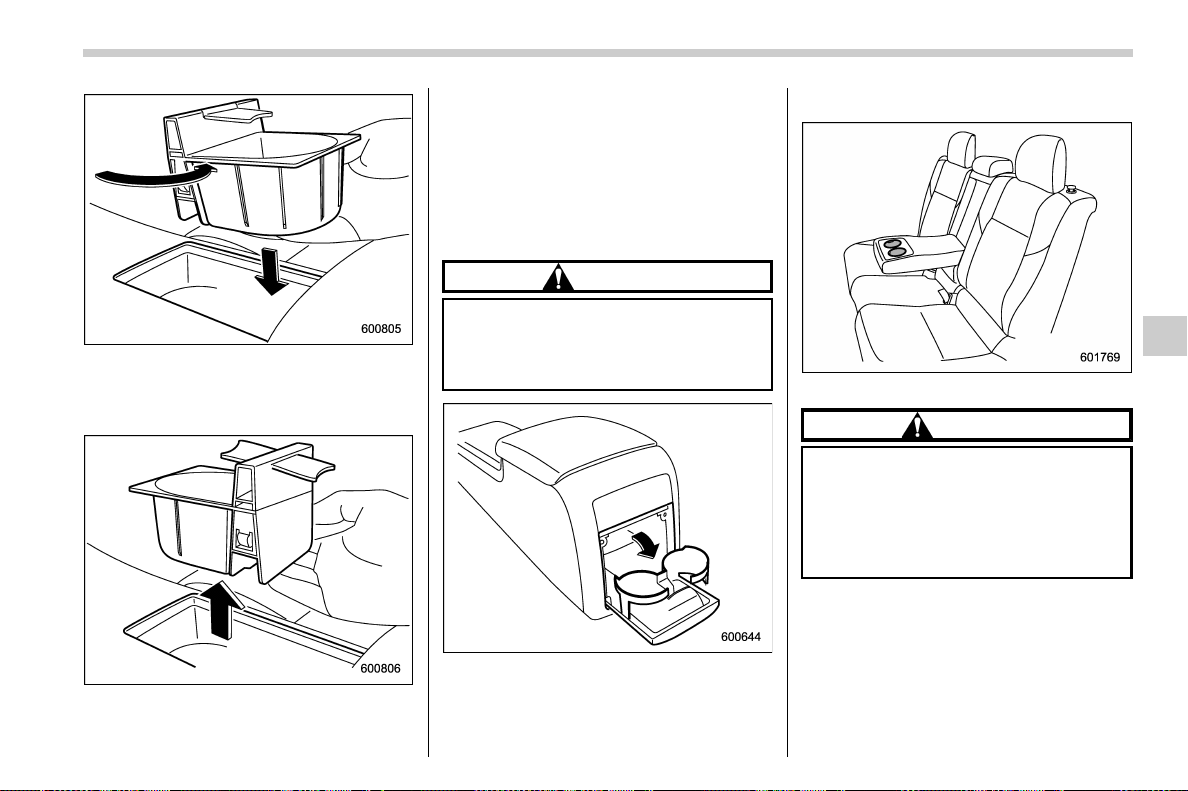
(345,1)
北米Model "A1700BE-B" EDITED: 2017/ 10/ 11
You can pull out the divider in the cup
holder and insert it in a different position
(further toward the front or rear) to enable
cups of different sizes to be held.
NOTE
With the divider taken out, you can use
the cup holder as a storage box.
& Rear passenger’s cup holder
! Type A
CAUTION
When not in use, always keep the
cup holder stored while driving to
reduce the risk of injury in the event
of a sudden stop or an accident.
A dual cup holder is located at the back of
the center console. To use the cup holder,
open the lid by pulling its upper edge.
! Type B
A dual cup holder is built into the armrest.
CAUTION
When a cup containing a beverage is
in the cup holder, do not fold down
the rear seats. Otherwise, the bev-
erage could spill while driving, and if
the beverage is hot, it could burn
you and/or your passengers.
Interior equipment/Cup holders
6-7
6
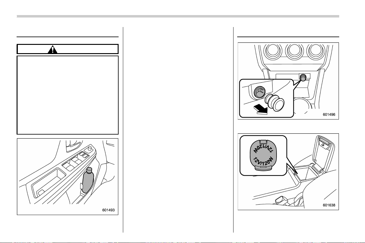
(346,1)
北米Model "A1700BE-B" EDITED: 2017/ 10/ 11
Bottle holders
CAUTION
. Do not pick up a bottle from the
bottle holder or put a bottle in the
holder while driving. Doing so
can distract you and lead to an
accident.
. When placing a beverage in a
bottle holder, make sure it is
capped. Otherwise, the beverage
could spill when opening/closing
the door or while driving and, if
the beverage is hot, it could burn
you and/or your passengers.
You can use the bottle holder equipped on
each door trim to hold a beverage bottle
and other items.
Accessory power outlets
Power outlet below the climate control
dials
Power outlet in the center console
Accessory power outlets are provided
Interior equipment/Bottle holders
6-8
(347,1)
北米Model "A1700BE-B" EDITED: 2017/ 10/ 11
below the climate control dials and in the
center console. Electrical power (12V DC)
from the battery is available at any of the
outlets when the ignition switch is in either
the “ACC” or “ON” position.
You can use an in-vehicle electrical appli-
ance by connecting it to an outlet.
The maximum power rating of an appli-
ance that can be connected is 120W.Do
not use an appliance which exceeds the
indicated wattage for each outlet.
When using appliances connected to two
or more outlets simultaneously, the total
power consumed by them must not ex-
ceed 120W.
CAUTION
. Do not attempt to use a cigarette
lighter in the accessory power
outlets.
. Do not place any foreign objects,
especially metal ones such as
coins or aluminum foil, into the
accessory power outlet. That
could cause a short circuit. Al-
ways put the cap on the acces-
sory power outlet when it is not in
use.
. Use only electrical appliances
which are designed for 12V DC.
The maximum power rating of an
appliance that can be connected
is 120W. Do not use an appliance
which exceeds the indicated wat-
tage for each outlet.
When using appliances con-
nected to two or more outlets
simultaneously, the total power
consumed by them must not
exceed 120W. Overloading the
accessory power outlet can
cause a short circuit. Do not use
double adapters or more than
one electrical appliance.
. If the plug on your electric appli-
ance is either too loose or too
tight for the accessory power
outlet, this can result in a poor
contact or cause the plug to get
stuck. Only use plugs that fit
properly.
. Use of an electric appliance in the
accessory power outlet for a long
period of time while the engine is
not running can cause battery
discharge.
. Before driving your vehicle, make
sure that the plug and the cord on
your electrical appliance will not
interfere with your shifting gears
and operating the accelerator
and brake pedals. If they do, do
not use the electrical appliance
while driving.
& Use with a cigarette lighter (if
equipped)
To use the accessory power outlet as a
cigarette lighter socket, purchase the
cigarette lighter plug, which is an optional
accessory. A cigarette lighter plug is
available from your SUBARU dealer.
The cigarette lighter operates only when
the ignition switch is in the “ON” or “ACC”
position.
To use the cigarette lighter, push in the
knob and wait a few moments. It will
automatically spring up when ready for
use.
WARNING
To avoid being burned, never grasp
the lighter by the end with the
heating element. Doing so could
result in injury and could also da-
mage the heating element.
– CONTINUED –
Interior equipment/Accessory power outlets
6-9
6

(348,1)
北米Model "A1700BE-B" EDITED: 2017/ 10/ 11
CAUTION
. Do not hold the lighter pushed in,
because it will overheat.
. The electrical power socket is
originally designed to use a gen-
uine SUBARU cigarette lighter
plug. Do not use a non-genuine
cigarette lighter plug in the sock-
et. Doing so may cause a short-
circuit and overheating, resulting
in a fire.
. If the socket is ever used for a
plug-in accessory such as a cell
phone, that may damage the
portion of the socket’s internal
mechanism that causes a cigar-
ette lighter plug to “pop out” after
its lighter el ement is h eated.
Therefore, do not place a cigar-
ette lighter plug in a socket that
has been used, even once, to
power a plug-in accessory. Doing
so may cause the plug to stick
and overheat, creating a potential
fire hazard.
Ashtray (if equipped)
CAUTION
Observe the following precautions.
Not doing so could result in a fire.
. Always extinguish matches and
cigarettes before putting them
into the ashtray, and then close
the ashtray securely.
. Do not put flammable material in
the ashtray.
. Do not leave a lighted cigarette in
the ashtray.
. Do not leave a lot of cigarette
butts in the ashtray.
NOTE
Particles of ash and tobacco will accu-
mulate around the hinges of the ash-
tray’s inner lid. Clean them off using a
toothbrush or a similar narrow-ended
implement.
You can install the portable ashtray in each
cup holder or bottle holder. For the loca-
tions of the cup holders, refer to “Cup
holders” F6-6. For the locations of the
bottle holders, refer to “Bottle holders” F6-
8.
When using the ashtray, open the lid of the
ashtray. Fully close the lid after using the
ashtray to help reduce residual smoke.
Interior equipment/Ashtray
6-10
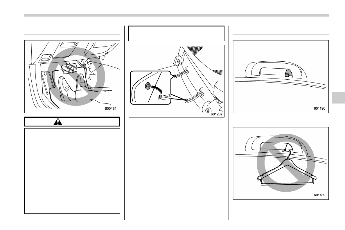
(349,1)
北米Model "A1700BE-B" EDITED: 2017/ 10/ 11
Floor mat (if equipped)
CAUTION
If the floor mat slips forward and
interferes with the movement of the
pedals while driving, it could cause
an accident. Observe the following
precautions to prevent the floor mat
from slipping forward.
. Be sure to use a genuine
SUBARU floor mat or an equiva-
lent designed with grommets in
the correct locations.
. Make sure that the driver’s floor
mat is placed in its proper loca-
tion and is correctly secured on
its retaining pins.
. Do not use more than one floor
mat.
Retaining pins are located on the driver’s
side floor.
Properly secure the floor mat using the
built-in grommets, by placing the grom-
mets over the pins and pushing them
downward.
Coat hook
The coat hook is attached to each rear
passenger’s hand grip.
– CONTINUED –
Interior equipment/Floor mat
6-11
6
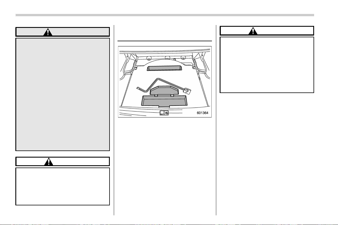
(350,1)
北米Model "A1700BE-B" EDITED: 2017/ 10/ 11
WARNING
Observe the following instructions.
. Do not hang coat hangers or
other hard or pointed objects on
the coat hooks. Hang clothing
directly on the coat hooks with-
out using hangers.
. Before hanging clothing on the
coat hooks, make sure there are
no pointed objects in the pock-
ets.
If these instructions are ignored, the
following may occur in sud den
stops or collisions, causing serious
injuries.
. Items may be thrown through the
cabin.
. SRS curtain airbags may be pre-
vented from deploying properly.
CAUTION
Never hang anything on the coat
hook that might obstruct the driver’s
view or that could cause injury in
sudden stops or in a collision. And
do not hang items on the coat hook
that weigh 11 lbs (5 kg) or more.
Under-floor storage compart-
ment
The storage compartment is located under
the floor of the trunk and can be used to
store small items. Pull the strap to open the
trunk floor lid, and then remove the lid.
NOTE
. The shape of the storage compart-
ment may be different depending on the
model.
. When storin g a flat tire, put the
storage tray in the trunk.
CAUTION
. Always keep the lids closed while
driving to reduce the risk of injury
in the event of a sudden stop or
an accident.
. Do not store spray cans, contain-
ers with flammable or corrosive
liquids or any other dangerous
items in the storage compart-
ment.
Interior equipment/Under-floor storage compartment
6-12
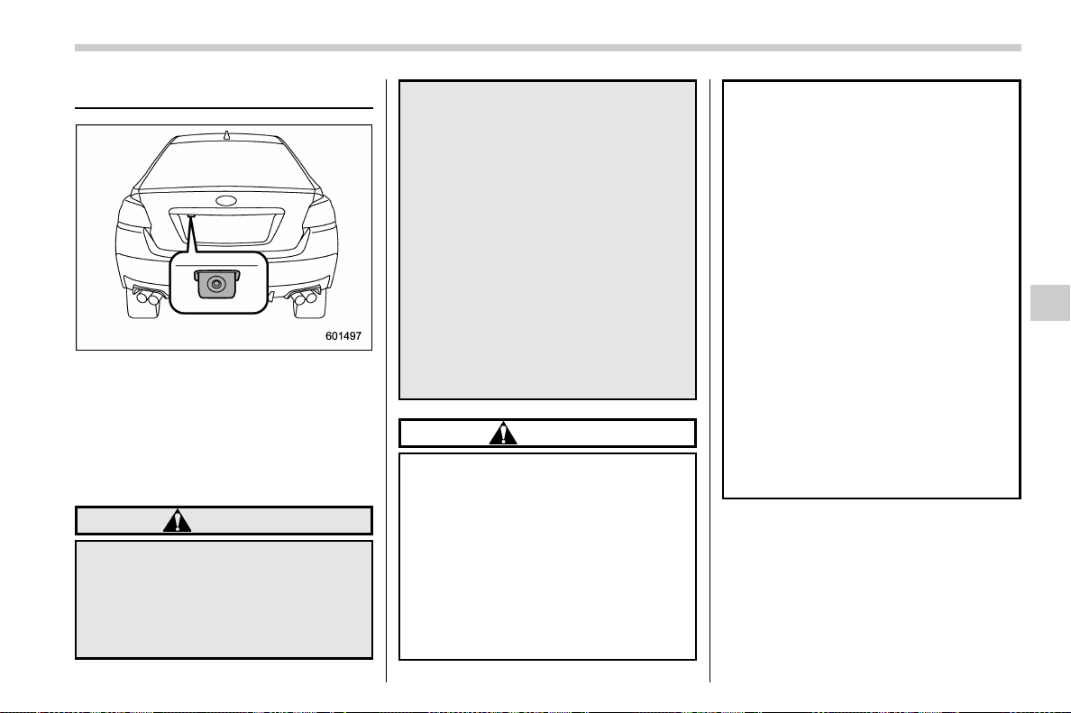
(351,1)
北米Model "A1700BE-B" EDITED: 2017/ 10/ 11
Rear view camera
A rear view camera is attached to the trunk
lid. When the ignition switch is “ON” and
the shift lever (MT models) or select lever
(CVT models) is set to “R”, the rear view
camera automatically displays the rear
view image behind the vehicle on the
monitor of the navigation system or the
audio display.
WARNING
. Since the rear view camera uses a
wide-angle lens, the image on the
monitor is different from the
actual view in terms of distance.
. Since the range and field of view
of the image on the monitor is
limited, you should always check
the rear view and the surrounding
area with your eyes and mirrors,
and move backward at a slow
speed. Moving backward only by
checking the rea r view image
from the camera could cause an
accident.
. Do not disassemble or modify the
camera, switch or wiring. If
smoke comes out or you smell a
strange odor, stop using the rear
view camera immediately. Con-
tact your SUBARU dealer for an
inspection. Continued use may
result in accident, fire or electric
shock.
CAUTION
. When washing your vehicle with
a high-pressure washer, do not
allow water to contact the camera
directly. Entry of water into the
camera lens may result in con-
densation, malfunction, fire or
electric shock.
. Since the camera is a precision
device, do not subject it to strong
impacts. Otherwise, malfunction,
fire or electric shock may occur.
. If mud or snow sticks to or is
frozen on the camera, you must
be very careful when removing it.
Otherwise, damage to the camera
maycauseafireorelectric
shock. Pour water or lukewarm
water over the camera to remove
mud and ice, and wipe it with a
soft, dry cloth.
. Do not put a flame close to the
camera or wiring. Otherwise, da-
mage or fire may occur.
. When replacing the fuse, be sure
to use a fuse with the specified
rating. Use of a fuse with a
different rating may result in a
malfunction.
. Do not use the rear view camera
for a long time while the engine is
not operating. Otherwise, the ve-
hicle battery may become com-
pletely discharged.
NOTE
. Do not wipe the camera with alcohol,
benzine or paint thinne r. Otherwise,
discoloration may occur. To remove
contamination, wipe the camera with a
cloth moistened with a diluted neutral
detergent and then wipe it with a soft,
dry cloth.
– CONTINUED –
Interior equipment/Rear view camera
6-13
6

(352,1)
北米Model "A1700BE-B" EDITED: 2017/ 10/ 11
. When waxing the vehicle, be careful
not to apply the wax to the camera. If it
comes in contact with the camera,
moisten a clean cloth with a diluted
neutral detergent to remove the wax.
. The camera lens has a hard coating
to help prevent scratches. However,
when washing the vehicle or cleaning
the camera lens, be careful not to
scratch the camera lens. Do not use a
washing brush directly on the camera
lens. The image quality of the rear view
camera may deteriorate.
. Strong light shined on the camera
lens may develop vertical lines around
the light source. This is not a malfunc-
tion.
. Under fluorescent light, the display
may flicker. However, this is not a
malfunction.
. The image of the rear view camera
may be slightly different from the actual
color of the objects.
& How to use the rear view
camera
When the shift lever (MT models) or select
lever (CVT models) is set to “R”, the rear
view camera automatically displays the
rear view image from the vehicle. When
the lever is set to other positions, the
image before setting to “R” is displayed.
1. Set the ignition switch to “ON”.
2. Set the shift lever (MT models) or
select lever (CVT models) to “R”.
NOTE
. The image of the rear view camera
has priority over other screen displays.
Therefore, while the rear view camera is
in operation, the operations of other
screens are disabled. To operate other
screens, set the shift lever or select
lever to a position other than “R”.
. The image of the rear view camera is
horizontally reversed as is the case
with the vehicle rear view mirror or the
side view mirror.
. It may be difficult to see the image of
the rear view camera in the following
cases. This is not a malfunction of the
camera.
– The vehicle is in a dark place (at
night, in a tunnel, etc.).
– The vehicle is in an extremely hot
or cold place.
– An object (such as raindrops,
snow, dirt, etc.) that disturbs the
view of the rear view camera sticks
to the lens of the camera.
– Strong light shined directly on
the camera lens (occasionally, there
are vertical lines on the screen).
! Rear view image cancel delay func-
tion
The rear view image cancel delay function
will keep the rear view image displayed
after shifting the shift lever/select lever out
of the “R” position before the screen
returns to the previous screen.
Interior equipment/Rear view camera
6-14
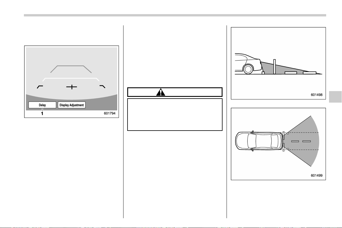
(353,1)
北米Model "A1700BE-B" EDITED: 2017/ 10/ 11
To turn on the rear view image cancel
delay function:
1. Touch the rear view image screen.
1) “Delay” key
2. Touch the “Delay” key.
It is possible to turn on/off the function by
touching the “Delay” key.
NOTE
If the rear view screen is not touched
for 5 seconds, both the “Delay” and
“Display Adjustment” keys will turn off.
Touch the rear view screen to display
the keys again.
When the rear view image cancel delay
function is on, the rear view image screen
can be automatically returned to the
previous screen if any of the following are
met.
. 9 seconds have passed since the shift
lever/select lever has shifted from the “R”
position to another position.
. The vehicle speed exceeds 5 mph (8
km/h).
. The select lever is shifted into the “P”
position (CVT models).
& Viewing range on the screen
CAUTION
The range that can be viewed with
the rear view camera is limited.
Always be sure to check with your
eyes when moving backward and
proceed slowly.
Range of view
Range of view
– CONTINUED –
Interior equipment/Rear view camera
6-15
6
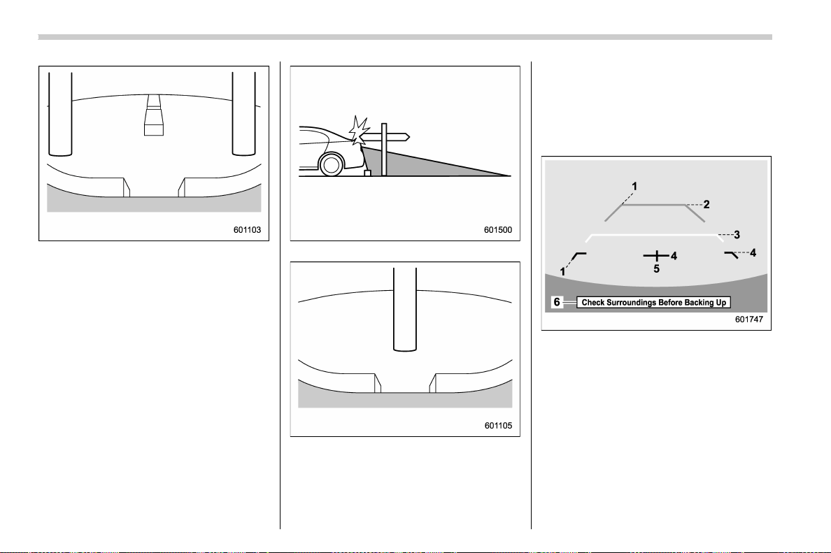
(354,1)
北米Model "A1700BE-B" EDITED: 2017/ 10/ 11
Image from camera
The area from the rear end of the bumper
can be viewed. Areas at both ends of the
bumper and areas just under the bumper
cannot be viewed.
Also, the image from the rear view camera
looks shorter than the actual distance.
Range of view
Image from camera
The area above the camera cannot be
viewed. If there is an object that has a wide
projection on its upper part such as a sign
pole behind the vehicle, the projection
cannot be seen on the screen.
& Help line
The help line (distance marker and vehicle
width line) is a guide to help you realize the
actual distance from the screen image.
Help lines
1) Vehicle width line (oblique vertical line)
2) Approx. 10 feet (3 m) from the bumper
(green horizontal line)
3) Approx. 3 feet (1 m) from the bumper
(yellow horizontal line)
4) Approx. 1.5 feet (0.5 m) from the bumper
(red horizontal line)
5) Vehicle centerline
6) Warning message
When the shift lever/select lever is set to
position “R”, the monitor screen displays
the help lines together with the rear view
Interior equipment/Rear view camera
6-16
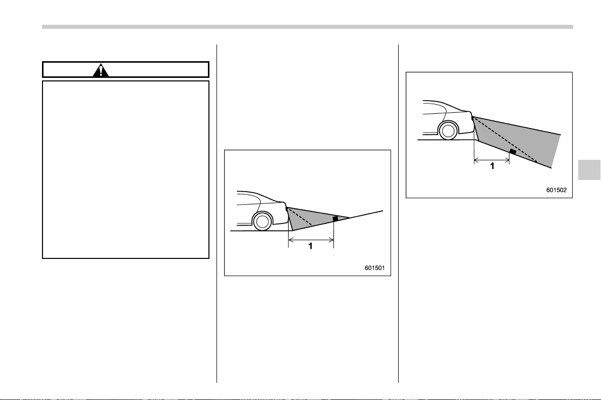
(355,1)
北米Model "A1700BE-B" EDITED: 2017/ 10/ 11
image.
CAUTION
. When moving backward, always
check the back with your eyes
without relying on the help lines.
. The actual position may be differ-
ent from the indication of the help
lines.
. Differences may occur due to
number of passengers or loaded
cargo.
. When the vehicle is on a slope or
when the vehicl e is i nclined
against the road, the indication
is different from the actual posi-
tion.
. Be sure to observe the displayed
warning message.
NOTE
If you shift to “R” within several
seconds after turning on the ignition
switch, the warning message may not
be displayed. After turning the ignition
switch “ON”, wait for several seconds,
and then shift to “R”. The wa rning
message will then be displayed.
! Difference between screen image
and actual road
The distance markers show the distance
for a level road when the vehicle is not
loaded. It may be different from the actual
distance depending on the loading condi-
tions or road conditions.
! When there is an upward slope at
the back
1) 3 feet (1 m)
The distance on the screen looks farther
than the actual distance.
! When there is a downward slope
at the back
1) 3 feet (1 m)
The distance on the screen looks nearer
than the actual distance.
NOTE
When cargo is loaded, the rear view
distance on the screen may look farther
than the actual distance as in an
upward slope.
– CONTINUED –
Interior equipment/Rear view camera
6-17
6
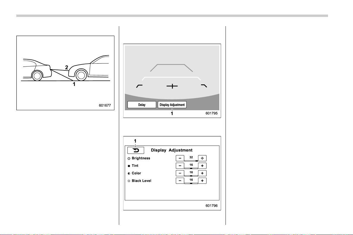
(356,1)
北米Model "A1700BE-B" EDITED: 2017/ 10/ 11
! Feature of distance marker
1) 3 feet (1 m) line
2) 10 feet (3 m) line
The distance marker shows the distance
on the road. If there is a car or other object
close behind, distance cannot be correctly
displayed.
& Display adjustment
1. Touch the rear view image screen.
1) Display Adjustment key
2. Touch the “Display Adjustment” key.
1) Back key
3. Touch “+” or “−” to change the setting.
4. After setting, touch the back key to
display the rear view image again.
Interior equipment/Rear view camera
6-18
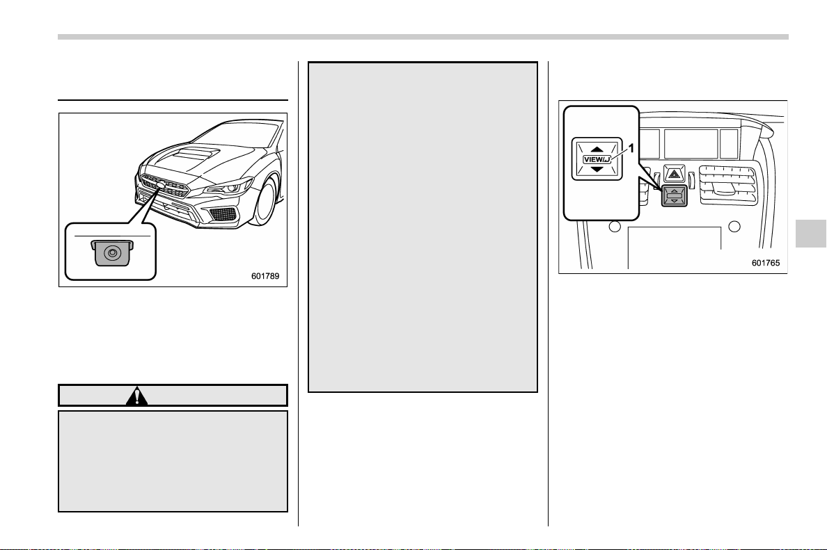
(357,1)
北米Model "A1700BE-B" EDITED: 2017/ 10/ 11
Front View Monitor (if
equipped)
The image from the camera mounted
inside the front grille is displayed in the
multi-function display (color LCD). This
eliminates blind spots and allows the driver
to che ck the forward direction of both
sides.
WARNING
. Never rely on only the Front View
Monitor when driving the vehicle.
The image on the monitor screen
may be different from the actual
situation. If you drive the vehicle
by viewing only the monitor im-
age, a collision or an unexpected
accident may occur. When driv-
ing the vehicle, always check the
traffic around the vehicle directly
with your eyes and the mirrors.
. Always operate the veh icle as
you would without the Front View
Monitor.
. Do not use the Front View Monitor
in the following situations.
– You are driving on a dirt road
or a road covered in snow.
– The camera malfunctions (e.g.
the lens or bracket is broken).
. If the outside temperature is low,
the monitor screen may become
dark or the image may become
dim. In particular, the image of a
moving object may be distorted
or disappear from the screen.
You must always check the traffic
around the vehicle directly with
your eyes when driving it.
& How to access the Front View
Monitor
1) VIEW switch
To change over to the camera screen,
perform either of the following operations
when the ignition switch is in the “ON”
position.
. Press the VIEW switch
. Shift the select lever from “R” to “D”
(only when the Camera Shift Link is set to
“On”) (for details, refer to “Camera shift link
setting” F3-58.)
– CONTINUED –
Interior equipment/Front View Monitor
6-19
6

(358,1)
北米Model "A1700BE-B" EDITED: 2017/ 10/ 11
& How to cancel the Front View
Monitor
! Manual cancellation
Press the VIEW switch again.
! Automatic cancellation
If any of the following conditions are met,
the Front View Monitor is canceled auto-
matically.
After accessing the Front View Monitor
by pressing the VIEW switch:
. You press the VIEW switch.
. Approximately 3 minutes have passed
since the last operation.
. The vehicle speed becomes 12.5 mph
(20 km/h) or more*.
. The select lever (CVT models) is
shifted to the “P” position.
. The parking brake is applied.
*: The Front View Monitor can be activated
when pressing the VIEW switch, regard-
less of the vehicle speed.
After accessing the Front View Monitor
by using the select lever:
. Shift t he select lever into the “P”
position.
. The vehicle speed becomes 5 mph (8
km/h) or more*.
. Approximately 9 seconds have passed
since the last operation.
. The parking brake is applied.
*: When the Front View Monitor is acti-
vated at speeds of more than 12.5 mph (20
km/h), to cancel the Front View Monitor,
the vehicle speed needs to be decreased
to less than 12.5 mph (20 km/h) and then
increased to more than 12.5 mph (20
km/h).
& Range of image on screen
A) Traffic intersection with a poor visibility
view
B) Parking facing a wall
1) Range of displayed image
2) Obstacles (e.g., buildings, fences or
other vehicles)
Interior equipment/Front View Monitor
6-20
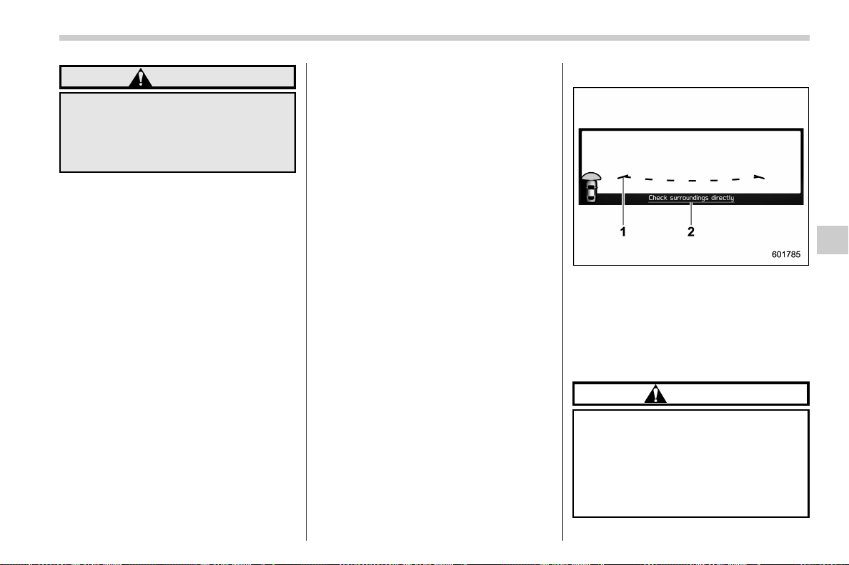
(359,1)
北米Model "A1700BE-B" EDITED: 2017/ 10/ 11
WARNING
Because the ran ge of the image
captured by the camera is limited,
always check the traffic around the
vehicle directly with your eyes when
driving the vehicle.
NOTE
. The range of the displayed image
may differ depending on the vehicle
status or the road surface status.
. Because the Front View Monitor
system uses a specially designed lens,
the sense of distance in the displayed
image is different from the actual dis-
tance.
. The camera image may be difficult to
view in the following situations. This is
not a malfunction.
– Dark place (at night)
– High or low temperature around
the lens
– Water contacts lens or in high
humidity (rainy weather)
– There is foreign materials (such
as mud) around the camera
– Sunlight or headlight beam di-
rectly shines towards the camera
lens
. Under an artificial light such as a
fluorescent lamp, sodium-vapor lamp
or mercury lamp, the lighted portion
may look like it is flickering (flicker
phenomenon).
. While the display has cooled down,
the image may leave traces or become
darker than usual, causing a difficulty
in viewing the screen. Always check the
traffic around the vehicle directly with
your eyes while driving the vehicle.
. The following incidents should not
be deemed a malfunction.
– The camera lens may become
foggy when the humidity is high on
a rainy day.
– The light from a vehicle or build-
ing located ahead may be reflected
towards t he camera image while
driving at night.
– In a dark place or while driving at
night, the camera image may be
adjusted to make noises less visi-
ble. Therefore, the image may look
like a monochromatic image or the
image colors may differ from the
actual colors. The camera image
may be deteriorated in regard to
sharpness at the center and four
corners of the screen. This is not a
malfunction.
& Guiding line
1) Guiding line
2) Warning message
The guiding line that indicates the width
and the front end of your vehicle is
displayed on the display.
& Handling of camera
CAUTION
Observe the following instructions.
Otherwise, the system may malfunc-
tion.
. Do not apply any strong impact to
the camera such as banging it or
hitting it with an object. The
mounting angle may change.
– CONTINUED –
Interior equipment/Front View Monitor
6-21
6
(360,1)
北米Model "A1700BE-B" EDITED: 2017/ 10/ 11
. The camera unit is a waterproof
structure. Do not attempt to re-
move, disassemble or modify the
unit.
. Do not rub strongly or polish the
camera lens with a hard brush or
abrasive compounds. The lens
may be scratched resulting in an
adverse effect to the camera
image.
. The camera lens is made of glass
or plastic. Do not allow any
organic solvent, body wax, oil
film remover or glass coating
agent to become attached on the
lens surface. If any becomes
attached, remove it immediately.
. Do not expose the camera lens to
any sudden temperature change,
for example, spraying hot water
on it in cold weather.
. Do not apply the water jet of a
high pressure washer to the cam-
era or the surrounding area when
cleaning the vehicle. The impact
by the strong water pressure may
cause the camera to come off.
Also, water may enter inside the
camera and cause a malfunction.
. If the camera is exposed to any
impact, it may lead to malfunction
of the camera. Have the camera
inspected by your SUBARU deal-
er as soon as possible.
. Do not use a steam cleaner under
any circumstances. Some types
of steam cleaners inject hot
steam.
. The camera surface may be da-
maged by a flying stone.
NOTE
If the camera lens is contaminated, no
sharp image is available. When the
camera is contaminated with water
drops, snow or mud, wash it with water
and wipe away any moisture with a soft
cloth. If it heavily gets dirty, wash it with
a neutral detergent.
Interior equipment/Front View Monitor
6-22

(363,1)
北米Model "A1700BE-B" EDITED: 2017/ 10/ 11
Fuel .......................................................................... 7-3
Fuel requirements .................................................. 7-3
Fuel filler lid and cap ............................................. 7-5
State emission testing (U.S. only) ......................... 7-7
Preparing to drive ................................................... 7-8
Starting and stopping the engine.......................... 7-9
General precautions when starting/stopping
engine ................................................................. 7-9
Models without push-button start systems ............ 7-10
Models with push-button start systems .. ............... 7-11
Remote engine start system (dealer option)...........7-14
Manual transmission ............................................ 7-16
Shifting speeds.....................................................7-17
Driving tips ........................................................... 7-18
Driver’s Control Center Differential
(C.DIFF/DCCD) (STI)........................................... 7-18
To change mode of driver’s control center
differential ..........................................................7-19
Auto mode............................................................ 7-20
Manual mode ........................................................7-21
Temporary release ................................................7-22
Continuously variable transmission.................... 7-23
Select lever...........................................................7-24
Selection of manual mode.....................................7-25
Shift lock function................................................. 7-27
Driving tips ........................................................... 7-28
SI-DRIVE (if equipped).......................................... 7-28
Intelligent (I) mode ................................................7-28
Sport (S) mode .....................................................7-29
Sport Sharp (S#) mode.......................................... 7-29
SI-DRIVE switch.................................................... 7-30
Limited slip differential (LSD) (STI)..................... 7-31
Power steering...................................................... 7-31
STI ....................................................................... 7-31
Except STI............................................................7-32
Braking .................................................................. 7-33
Braking tips..........................................................7-33
Brake system ....................................................... 7-33
Disc brake pad wear warning indicators................7-34
High performance brake system (STI) ................... 7-34
Red caliper with sports brake pad (if equipped) .... 7-34
ABS (Anti-lock Brake System)............................. 7-35
ABS self-check ..................................................... 7-35
ABS warning light.................................................7-35
Electronic Brake Force Distribution (EBD)
system ................................................................ 7-36
Steps to take if EBD system malfunctions............. 7-36
Vehicle Dynamics Control system ...................... 7-37
Vehicle Dynamics Control system monitor ............7-39
Vehicle Dynamics Control OFF switch...................7-39
Tire pressure monitoring system (TPMS)
(U.S.-spec. models) ........................................... 7-40
Parking your vehicle ............................................ 7-42
Parking brake (models without electronic parking
brake system)....................................................7-42
Electronic parking brake (models with electronic
parking brake system) .......................................7-43
Parking tips.......................................................... 7-45
Auto Vehicle Hold function .................................. 7-46
To turn on/off the Auto Vehicle Hold function ........ 7-47
To operate the Auto Vehicle Hold function ............ 7-48
Starting and operating
7

(364,1)
北米Model "A1700BE-B" EDITED: 2017/ 10/ 11
To release the Auto Vehicle Hold function .............7-48
Tips ...................................................................... 7-48
Hill start assist system......................................... 7-49
To activate/deactivate the Hill start assist system
(models without the electronic parking brake
system)...............................................................7-51
Hill start assist warning light/Hill start assist OFF
indicator light (models without the electronic
parking brake system)......................................... 7-53
Cruise control ....................................................... 7-53
To set cruise control .............................................7-54
To temporarily cancel the cruise control................7-55
To turn off the cruise control.................................7-55
To change the cruising speed ...............................7-55
Cruise control indicator ........................................7-56
Cruise control set indicator ...................................7-56
BSD/RCTA (if equipped) ....................................... 7-57
System features....................................................7-57
System operation ................................................. 7-59
BSD/RCTA approach indicator light/warning
buzzer ............................................................... 7-60
BSD/RCTA warning indicator ................................7-62
BSD/RCTA OFF switch.......................................... 7-63
Certification for the BSD/RCTA .............................7-64
Handling of radar sensors .................................... 7-65
Reverse Automatic Braking System
(if equipped) ....................................................... 7-66
Reverse Automatic Braking System overview........7-67
Operating conditions ............................................ 7-67
Reverse Automatic Braking System operation....... 7-70
Canceling the Reverse Automatic Braking
system operation...............................................7-74
Reverse Automatic Braking system ON/OFF
setting............................................................... 7-74
RAB warning indicator..........................................7-75
Handling of the sonar sensors .............................. 7-75
Starting and operating
(365,1)
北米Model "A1700BE-B" EDITED: 2017/ 10/ 11
Fuel
CAUTION
Use of a fuel which is low in quality
or use of an inappropriate fuel
additive may cause engine damage.
& Fuel requirements
! STI
The engine is designed to operate at
maximum performance using unleaded
gasoline with an octane rating of 93 AKI
(98 RON) or higher. If 93 AKI (98 RON)
fuel is not readily available in your area,
unleaded gasoline with an octane rating of
91 AKI (95 RON) may be used with no
detriment to engine durability or driveabil-
ity. However, you may notice a slight
decrease in maximum engine perfor-
mance while using 91 AKI (95 RON) fuel.
Use of 91 AKI (95 RON) fuel will not affect
your warranty coverage.
! Except STI
The engine is designed to operate using
unleaded gasoline with an octane rating
of 91 AKI (95 RON) or higher. If 91 AKI
(95 RON) fuel is not readily available,
unleaded gasoline with an octane rating of
87 AKI (90 RON) may be used.
Regular unleaded gasoline with an octane
rating of 87 AKI (90 RON) or higher may
also be used. Using regular unleaded
gasoline will not be detrimental to engine
durability, nor will it affect your warranty
coverage. However, depending on your
driving habits and conditions, you may
notice a decrease in maximum engine
performance, fuel economy or slight en-
gine vibration or knocking. If you experi-
ence any of these conditions while using a
lower octane rated fuel, you may want to
return to using 91 AKI (95 RON) octane
rated fuel as soon as possible. Addition-
ally, if your vehicle knocks heavily or
persistently, the use of 91 AKI (95 RON)
or higher grade unleaded gasoline is
required.
! Fuel octane rating
Using a gasoline with a lower octane rating
can cause persistent and heavy knocking,
which can damage the engine. Do not be
concerned if your vehi cle sometimes
knocks lightly when you drive up a hill or
when you accelerate. Cont act your
SUBARU dealer if you use a fuel with the
specified octane rating and your vehicle
knocks heavily or persistently.
! RON
This octane rating is the Research Octane
Number.
! AKI
This octane rating is the average of the
Research Octane and Motor Octane num-
bers and is commonly referred to as the
Anti Knock Index (AKI).
! Unleaded gasoline
The neck of the fuel filler pipe is designed
to accept only an unleaded gasoline filler
nozzle. Under no circumstances should
leaded gasoline be used because it will
damage the emission control system and
may impair driveability and fuel economy.
! Gasoline for California-certified
LEV
If your vehicle was certified to California’s
low emission vehicle (LEV) standards as
indicated on the underhood tune-up label,
it is designed to opt imize engine and
emission performance with gasoline that
meets the clean burning low-sulfur Cali-
fornia gasoline specifications. If you live in
any other state than California, your
vehicle will operate on gasoline meeting
Federal specifications. Gasoline sold out-
side California is permitted to have higher
sulfur levels, which may affect the perfor-
mance of your vehicle’s catalytic converter
– CONTINUED –
Starting and operating/Fuel
7-3
7
(366,1)
北米Model "A1700BE-B" EDITED: 2017/ 10/ 11
and may produce a sulfur exhaust odor or
smell. SUBARU recommends that you try
a different brand of unleaded gasoline
having lower sulfur to determine if the
problem is fuel related before returning
your vehicle to an authorized dealer for
service.
! MMT
Some gasoline contains an octane-enhan-
cing additive called MMT (Methylcyclo-
penta dienyl Manganese Tricarbonyl). If
you use such fuels, your emission control
system performance may deteriorate and
the CHECK ENGINE warning light/Mal-
function indicator light may turn on. If this
happens, return to your authorized
SUBARU Dealer for service. If it is
determined that the condition is caused
by the type of fuel used, repairs may not be
covered by your warranty.
! Gasoline for cleaner air
Your use of gasoline with detergent ad-
ditives will help prevent deposits from
forming in your engine and fuel system.
This helps keep your engine in tune and
your emission control s ystem working
properly, and is a way of doing your part
for cleaner air. If you continuously use a
high quality fuel with the proper detergent
and other additives, you should never
need to add any fuel system cleaning
agents to your fuel tank.
Many gasolines are now blended with
materials called oxygenates. Use of these
fuels can also help keep the air cleaner.
Oxygenated blend fuels, such as ethanol
(ethyl or grain alcohol) may be used in your
vehicle, but should contain no more than
10% ethanol for the proper operation of
your SUBARU.
Do not use any gasoline that contains
more than 10% ethanol, including from any
pump labeled E15, E30, E50 or E85 (which
are only some examples of fuel containing
more than 10% ethanol).
In addition, some gasoline suppliers are
now produ cing reformulated gasolines,
which are designed t o reduce vehicle
emissions. SUBARU approves the use of
reformulated gasoline.
If you are not sure what the fuel contains,
you should ask your service station op-
erators if their gasolines contain deter-
gents and oxygenates and if they have
been reformulated to reduce vehicle emis-
sions.
As additional guidance, only use fuels
suited for your vehicle as explained in the
following description.
. Fuel should be unleaded and have an
octane rating no lower than that specified
in this manual.
. Methanol (methyl or wood alcohol) is
sometimes mixed with unleaded gasoline.
Methanol can be used in your vehicle
ONLY if it does not exceed 5% of the fuel
mixture AND if it is accompanied by
sufficient quantities of the proper cosol-
vents and corrosion inhibitors required to
prevent damage to the fuel system. Do not
use fuel con taining methanol EXCEPT
under these conditions.
. If undesirable driveability problems are
experienced and you suspect they may be
fuel related, try a different brand of gaso-
line before seeking service at your
SUBARU dealer.
. Fuel system damage or driveability
problems which result from the use of
improper fuel are not covered under the
SUBARU Limited Warranty.
CAUTION
Do not let fuel spill on the exterior
surfaces of the vehicle. Fuels con-
taining alcohol may ca use paint
damage, which is not covered under
the SUBARU Limited Warranty.
Starting and operating/Fuel
7-4
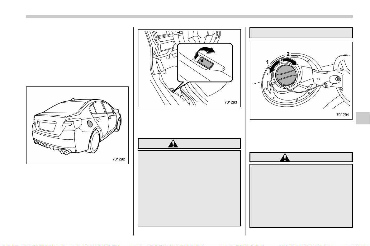
(367,1)
北米Model "A1700BE-B" EDITED: 2017/ 10/ 11
& Fuel filler lid and cap
! Refueling
Only one person should be involved in
refueling. Do not allow others to approach
the area of the vehicle near the fuel filler
pipe while refueling is in progress.
Be sure to observe any other precautions
that are posted at the service station.
Fuel lid release lever
1. To open the fuel filler lid, pull the lid
release lever up. The lever is on the floor at
the left of the driver’s seat.
WARNING
Before opening the fuel filler cap,
first touch the vehicle body or a
metal portion of the fuel pump or
similar object to discharge any sta-
tic electricity that may be present on
your body. If your body is carrying
an electrostatic charge, there is a
possibility that an electric spark
could ignite the fuel, which could
burn you. To avoid acquiring a new
static electric charge, do not get
back into the vehicle while refueling
is in progress.
1) Open
2) Close
2. Remove the fuel filler cap by turning it
slowly counterclockwise.
WARNING
. Gasoline vapor is highly flam-
mable. Before refueling, always
first stop the engine and close all
vehicle doors and windows.
Make su re that there a re no
lighted cigarettes, open flames
or electrical sparks in the adja-
cent area. Only handle fuel out-
doors. Quickly wipe up any
spilled fuel.
– CONTINUED –
Starting and operating/Fuel
7-5
7
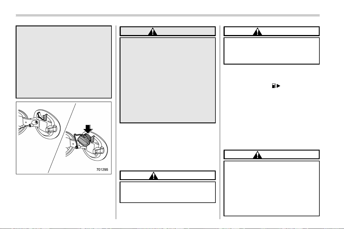
(368,1)
北米Model "A1700BE-B" EDITED: 2017/ 10/ 11
. When opening the cap, grasp it
firmly and turn it slowly to the left.
Do not remove the cap quickly.
Fuel may be under pressure and
spray out of the fuel filler neck,
especially in hot weather. If you
hear a hissing sound while you
are removing the cap, wait for the
sound to stop and then slowly
open the cap to prevent fuel from
spraying out and creating a fire
hazard.
3. Set the fuel filler cap on the cap holder
inside the fuel filler lid.
WARNING
. When refueling, insert the fuel
nozzle securely into the fuel filler
pipe. If the nozzle is lifted or not
fully inserted, its automatic stop-
ping mechanism may not func-
tion, causing fuel to overflow the
tank and creating a fire hazard.
. Stop refueling when the auto-
matic stop mechanism on the
fuel nozzle activates. If you con-
tinue to add fuel, temperature
changes or other conditions
may cause fuel to overflow from
the tank and create a fire hazard.
4. Stop filling the tank after the fuel filler
pump automatically stops. Do not add any
more fuel.
5. Put the cap back on, turn it clockwise
until you hear a clicking noise. Be certain
not to catch the tether under the cap while
tightening.
CAUTION
Make sure that the cap is tightened
until it clicks to prevent fuel spillage
in the event of an accident.
6. Close the fuel filler lid completely.
CAUTION
If you spill any fuel on the painted
surface, rinse it off imme diately.
Otherwise, the painted surface
could be damaged.
NOTE
. You will see the “ ” sign in the fuel
gauge. This indicates that the fuel filler
door (lid) is located on the right side of
the vehicle.
. If the fuel filler cap is not tightened
until it clicks or if the tether is caught
under the cap, the CHECK ENGINE
warning light/malfunction indicator
light may illuminate. Refer to “CHECK
ENGINE warning light/Malfunction in-
dicator light ” F3-16.
CAUTION
. Never add any cleaning agents to
the fuel tank. The addition of a
cleaning agent may cause da-
mage to the fuel system.
. After refueling, turn the cap
clockwise until it clicks to ensure
that it is fully tightened. If the cap
is not securely tightened, fuel
may leak out while the vehicle is
Starting and operating/Fuel
7-6
(369,1)
北米Model "A1700BE-B" EDITED: 2017/ 10/ 11
being driven or fuel spillage
could occur in the event of an
accident, creating a fire hazard.
. Do not let fuel spill on the exterior
surfaces of the vehicle. Because
fuel may damage the paint, be
sure to wipe off any spilled fuel
quickly. Paint damage caused by
spilled fuel is not covered under
the SUBARU Limited Warranty.
. Always use a genuine SUBARU
fuel filler cap. If you use the
wrong cap, it may not fit or have
proper venting and your fuel tank
and emission control system
may be damaged. It could also
lead to fuel spillage and a fire.
. Immediately put fuel in the tank
whenever the low fuel warning
light illuminates. Engine misfires
as a result of an empty tank could
cause damage to t he engine.
Continuing to operate your vehi-
cle at an extremely low fuel level
may result in a reduction of
engine performance.
State emission testing
(U.S. only)
WARNING
Only use a four-wheel dynamometer
when testing an All-Wheel Drive
(AWD) model.
TestingofanAWDmodelmust
NEVER be performed on a single
two-wheel dynamometer. Attempt-
ing to do so will result in uncon-
trolled vehicle movement and may
cause an accide nt or injuries to
persons nearby.
CAUTION
. At state inspection time, remem-
ber to tell your inspection or
service station in advance not to
place your SUBARU AWD vehicle
on a two-wheel dynamometer.
Otherwise, serious transmission
damage will result.
. Resultant vehicle damage due to
improper testing is not covered
under the SUBARU Limited War-
ranty and is the responsibility of
the state inspection program or
its contractors or licensees.
California and a number of federal states
have Inspection/Maintenance programs to
inspect your vehicle’s emission control
system. If your vehicle does not pass this
test, some states may deny renewal of
your vehicle’s registration.
Your vehicle is equipped with a computer
that monitors the performance of the
engine’s emission control system. Certi-
fied emission inspectors will inspect the
On-Board Diagnostic (OBDII) system as
part of the state emission inspection
process. The OBDII system is designed
to detect engine and transmission pro-
blems that might cause the vehicle emis-
sions to exceed allowable limits. OBDII
inspections apply to all 1996 model year
and newer passenger cars and trucks.
Over 30 states plus the District of Colum-
bia have implemented emission inspection
of the OBDII system.
. The inspection of the OBDII system
consists of a visual operational check of
the “CHECK ENGINE” warning light/mal-
function indicator light (MIL) and an ex-
amination of the OBDII system with an
electronic scan tool.
. A vehicle passes the OBDII system
inspection if proper operation of the
“CHECK ENGINE” warning light is ob-
– CONTINUED –
Starting and operating/State emission testing (U.S. only)
7-7
7

(370,1)
北米Model "A1700BE-B" EDITED: 2017/ 10/ 11
served, there are no stored diagnostic
trouble codes, and the OBDII readiness
monitors are all complete.
. A vehicle fails the OBDII inspection if
the “CHECK ENGINE” warning light is not
properly operating (light is illuminated or is
not working due to faulty LED [Light
Emitting Diode]) or there is one or more
diagnostic trouble codes stored in the
vehicle’s computer.
. A state emission inspection may reject
(not pass or fail) a vehicle if the number of
OBDII system readiness monitors “NOT
READY” is greater than one. If the
vehicle’s battery has been recently re-
placed or disconnected, the OBDII system
inspection may indicate that the vehicle is
not ready for the emission test. Under this
condition, the vehicle driver should be
instructed to drive his/her vehicle for a
few days to reset the readiness monitors
and return for an emission re-inspection.
. Owners of rejected or failing vehicles
should contact their SUBARU Dealer for
service.
Some states still use dynamometers in
their emission inspection program. A
dynamometer is a treadmill or roller-like
testing device that allows your vehicle’s
wheels to turn while the vehicle remains in
one place. Prior to your vehicle being put
on a dynamometer, tell your emi ssion
inspector not to place your SUBARU
AWD vehicle on a two-wheel dynam-
ometer. Otherwise, serious transmis-
sion damage will result.
The U.S. Environmental Protection
Agency (EPA) and states using two-wheel
dynamometers in their emission testing
program hav e EXEMPTED SUBARU
AWD vehicles f rom the portion of the
testing program that involves a two-wheel
dynamometer. There are some states that
use four-wheel dynamometers in their
testing program. When properly used, this
equipment should not damage a SUBARU
AWD vehicle.
Under no circumstances should the rear
wheels be j ac ked off the ground, no r
should the driveshaft be disconnected in
an attempt to bypass AWD for s tate
emission testing. An AWD vehicles must
be tested using an AWD dynamometer
with all 4 wheels driven and loaded.
Preparing to drive
You should perform the following checks
and adjustments every day before you
start driving.
1. Check that all windows, mirrors, and
lights are clean and unobstructed.
2. Check the appearance and condition
of the tires. Also check tires for proper
inflation.
3. Look under the vehicle for any sign of
leaks, and check that no small animal is
under the vehicle.
4. Check that no small animal enters the
engine compartment.
5. Check that the hood and trunk lid are
fully closed.
6. Check the adjustment of the seat.
7. Check the adjustment of the inside and
outside mirrors.
8. Fasten your seatbelt. Check that your
passengers have fastened their seatbelts.
9. Check the operation of the warning
and indicator lights when the ignition
switch is turned to the “ON” position.
10. Check the gauges, indicator and warn-
ing lights after starting the engine.
Starting and operating/Preparing to drive
7-8
(371,1)
北米Model "A1700BE-B" EDITED: 2017/ 10/ 11
CAUTION
Trapping small animals in the cool-
ing fan and belts of the engine may
result in a malfunction. Check that
no small animal enters the engine
compartment and under the vehicle
before starting the engine.
NOTE
Engine oil, engine coolant, brake fluid,
washer fluid and other fluid levels
should be checked daily, weekly or at
fuel stops.
Starting and stopping the en-
gine
& General precautions when
starting/stopping engine
WARNING
. Never start the engine from out-
side the vehicle. It may result in
an accident.
. Do not start the engine near dry
foliage, paper, or other flammable
substances. The exhaust pipe
and exhaust emissions can cre-
ate a fire hazard at high tempera-
tures.
. Do not leave the engine running
in locations with poor ventilation,
such as a garage and indoors.
The exhaust gas may enter the
vehicle or indoors, and it may
result in carbon monoxide poi-
soning.
CAUTION
. Do not stop the engine while
driving. Otherwise, the catalyst
may overheat and burn.
. When starting the engine, be sure
to sit in the driver’s seat (except
when using the remote engine
start system).
NOTE
. Avoid rapid acceleration immedi-
ately after the engine has started. In
addition, always avoid rapid racing.
. Until the engine is warmed up suffi-
ciently, the engine speed is maintained
high. The engine speed will gradually
drop as the engine warms up.
. On rare occasions, it may be difficult
to start the engine depending on the
fuel used and the driving condition
(repeated short trips when the engine
is not warmed up sufficiently). In such
cases, it is recommended to switch to a
different brand of fuel.
. On rare occasions, transient knock-
ing may be heard from the engine when
the accelerator is operated rapidly such
as a rapid start-up and a rapid accel-
eration. This is not a malfunction.
. The engine starts more easily when
the headlights, air conditioner and rear
window defogger are turned off.
. It may be difficult to start the engine
when the batter y has been dis co n-
nected and reconnected (for mainte-
nance or other purposes). This diffi-
culty is caused by the electronically
– CONTINUED –
Starting and operating/Starting and stopping the engine
7-9
7
(372,1)
北米Model "A1700BE-B" EDITED: 2017/ 10/ 11
controlled throttle’s self-diagnosis
function. To overcome it, keep the
ignition switch in the “ON” position
for approximately 10 seconds before
starting the engine.
& Models without push-button
start systems
! Starting engine
CAUTION
Do not operate the starter motor
continuously for more than 10 sec-
onds. If the engine fails to start after
operating the starter for 5 to 10
seconds, wait for 10 seconds o r
more before trying again.
NOTE
Do not shift the shift lever/select lever
while the starter is cranking.
! MT models
1. Apply the parking brake.
2. Turn off unnecessary lights and acces-
sories.
3. Depress the clutch pedal to the floor
and shift the shift lever into neutral. Hold
the clutch pedal to the floor while starting
the engine.
The starter motor will only operate when
the clutch pedal is depressed fully to the
floor.
4. Turn the ignition switch to the “ON”
position and check the operation of the
warning and indicator lights. Refer to
“Warning and indicator lights” F3-13.
5. Turn the ignition switch to the “START”
position without depressing the accelera-
tor pedal. Release the key immediately
after the engine has started.
If the engine does not start, perform the
procedure described in “If the engine does
not start” F7-11.
6. Confirm that all warning and indicator
lights have turned off after the engine has
started.
! CVT models
1. Apply the parking brake.
2. Turn off unnecessary lights and acces-
sories.
3. Shift the select lever to the “P” or “N”
position (preferably the “P ” position).
The starter motor will only operate when
the select lever is at the “P” or “N” position.
4. Turn the ignition switch to the “ON”
position and check the operation of the
warning and indicator lights. Refer to
“Warning and indicator lights” F3-13.
5. Turn the ignition switch to the “START”
position without depressing the accelera-
tor pedal. Release the key immediately
after the engine has started.
If the engine does not start, perform the
procedure described in “If the engine does
not start” F7-11.
6. Confirm that all warning and indicator
lights have turned off after the engine has
started.
While the engine is warming up, make sure
that the select lever is at the “P” or “
N”
position and that the parking brake is
applied.
CAUTION
If you restart the engine while the
vehicle is moving, shift the select
lever into the “N” position. Do not
attempt to place the select lever of a
moving vehicle into the “P” position.
Starting and operating/Starting and stopping the engine
7-10
(373,1)
北米Model "A1700BE-B" EDITED: 2017/ 10/ 11
! If the engine does not start
CAUTION
For safety, release the accelerator
pedal as soon as the engine starts.
Try the following procedure.
1. Turn the ignition switch to the “LOCK”
position and wait for at least 10 seconds.
2. After checking that the parking brake is
firmly set, turn the ignition switch to the
“START” position while depressing the
accelerator pedal slightly (approximately
a quarter of the full stroke).
3. If this fails to start the engine, turn the
ignition switch back to the “LOCK” position
and wait for at least 10 seconds.
4. Fully depress the accelerator pedal
and turn the ignition switch to the “START”
position.
If this fails to start the engine, try the
following procedure.
1. Turn the ignition switch again to the
“LOCK” position.
2. After waiting for 10 seconds or longer,
turn the ignition switch to the “START”
position without depressing the accelera-
tor pedal.
If the engine still does not start, contact
your nearest SUBARU dealer for assis-
tance.
! Stopping the engine
The ignition switch should be turned off
only when the vehicle is stopped and the
engine is idling.
WARNING
Do not stop the engine when the
vehicle is moving. This will cause
loss of power to the power steering
and the brake booster, making steer-
ing and braking more difficult. It
could also result in accidental acti-
vation of the “LOCK” position on the
ignition switch, causing the steering
wheel to lock.
& Models with push-button
start systems
! Safety precautions
Refer to “Safety precautions ” F2-8.
! Operating range for push-button
start system
Refer to “Operating range” F3-6.
! Starting engine
WARNING
If the indicator on the push-button
ignition switch flashes in green after
the engine has started, never drive
the vehicle. The steering is still
locked, and it may result in an
accident. In this case, press the
push-button ignition switch with
the brake pedal depressed and with
the steering wheel turned from the
right to the left.
CAUTION
. When the operation indicator on
the push-button ignition switch is
flashing in orange, there may be a
malfunction with the vehicl e.
Contact a SUBARU dealer imme-
diately.
. Do not continue pressing the
push-button ignition switch for
more than 10 seconds. Doing so
could cause a malfunction. If the
engine does not start, stop press-
ing the push-button ignition
switch. Instead, press the push-
buttonignitionswitchwithout
depressing the brake pedal to
– CONTINUED –
Starting and operating/Starting and stopping the engine
7-11
7
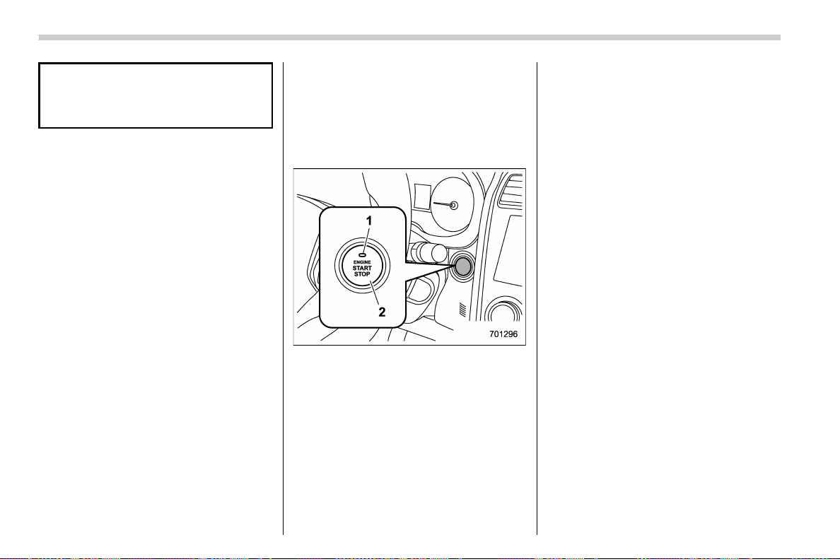
(374,1)
北米Model "A1700BE-B" EDITED: 2017/ 10/ 11
switch the power status to “OFF”.
Wait 10 seconds, and then push
the push-button ignition switch
to start the engine.
NOTE
. When pressing the push-button igni-
tion switch with the clutch pedal (MT
models) or the brake pedal (CVT mod-
els) depressed:
– The engine starter operates for a
maximum of 10 seconds and after
starting the engine, the starter stops
automatically.
– You can start the engine regard-
less of the power status.
. If the engine does not start, check
the security indicator light. Then press
the push-button ignition switch without
depressing the clutch pedal (MT mod-
els) or the brake pedal (CVT models) to
switch the power to “OFF”.
– If the light had illuminated, try to
start the engine again.
– If the light had been off, press the
push-button ignition switch while
depressing the clutch pedal (MT
models) or the brake pedal (CVT
models) more forcefully.
. The engine may not start depending
on the radio wave conditions around
the vehicle. In such a case, refer to
“Starting engine” F9-27.
. If the vehicle battery is discharged,
the steering cannot be u nlocked.
Charge the battery.
. Do not shift the shift lever/select
lever while the starter is cranking.
1) Operation indicator
2) Push-button ignition switch
The design of the push-button ignition
switch may be slightly different depending
on the models.
When you press the push-button ignition
switch with the clutch pedal (MT models)/
brake pedal (CVT models) depressed, the
engine will start. The start procedure of the
engine is as follows.
! MT models
1. Carry the access key fob, and sit in the
driver’s seat.
2. Apply the parking brake.
3. Shift the shift lever in neutral.
4. Depress the brake pedal.
5. Depress the clutch pedal until the
indicator on the push-button ignition switch
turns green.
6. While de pres sing the clutch pedal,
press the push-button ignition switch.
! CVT models
1. Carry the access key fob, and sit in the
driver’s seat.
2. Apply the parking brake.
3. Shift the select lever in the “P” position.
The engine can also start when the select
lever is in the “N” position, however, for
safety reasons, start in the “P” position.
4. Depress the brake pedal until the
operation indicator on the push-button
ignition switch turns green. When starting
with the select lever in the “N” position, the
indicator does not turn green.
5. While depressing the brake pedal,
press the push-button ignition switch.
Starting and operating/Starting and stopping the engine
7-12
(375,1)
北米Model "A1700BE-B" EDITED: 2017/ 10/ 11
NOTE
. While pressing the select lever but-
ton in, the indicator on the push-button
ignition switch will not turn green even
when the select lever is in the “P”
position.
. When the engine is not started, the
brake pedal may feel stiff. In such a
case, depress the brake pedal more
forcefully than usual. Check that the
operation indicator on the push-button
ignition switch turns green, and press
the push-button ignition switch to start
the engine.
! In case of the engine does not
start by the normal engine start
procedure
1. Move the shift lever to the neutral
position (MT models), or move the select
lever to the “P ” position (CVT models).
2. Switch the power status to “ACC”.
3. Press and hold the push-button ignition
switch for at least 15 seconds with the
clutch pedal (MT model s)/ bra k e pedal
(CVT models) depressed.
Although the engine may start, only use
this procedure in the case of an emer-
gency. If the engine still does not start,
refer to “Starting engine” F9-27.
! Stopping engine
1. Stop the vehicle completely.
2. Move the select lever to the “P”
position (CVT models).
3. Press the push-button ignition switch.
The engine will stop, and the power will be
switched to “OFF”.
WARNING
. Do not touch the push-button
ignition switch while driving.
When you operate the push-but-
ton ignition switch as follows, the
engine will stop.
– Pressing and holding the
switch for 3 seconds or longer.
– Pressing the switch briefly 3
times or more in succession.
When the engine stops, the brake
booster will not function. A great-
er foot pressure will be required
on the brake pedal.
The power steering system will
not operate either. A greater force
will be required to steer, and it
may result in an accident.
. If the engine stops while driving,
do not operate the push-button
ignition switch or open any of the
doors until the vehicle is stopped
in a safe location. It is dangerous
because the steering m ay be
locked. Stop the vehicle in a safe
location, and contact a SUBARU
dealer immediately.
CAUTION
For CVT models:
. Do not stop the engine while the
select lever is in a position other
than the “P” position.
. If the engine is stopped while the
select lever is in a position other
than the “P” position, the power
will be in “ACC”. If the vehicle is
left in this condition, the battery
may be discharged.
NOTE
Although you can stop the engine by
operating the push-button ignition
switch, do not stop the engine while
driving except in an emergency.
– CONTINUED –
Starting and operating/Starting and stopping the engine
7-13
7

(376,1)
北米Model "A1700BE-B" EDITED: 2017/ 10/ 11
! When access key fob does not
operate properly
Refer to “Access key fob – if access key
fob does not operate properly” F9-26.
& Remote engine start system
(dealer option)
WARNING
. Do not remote start a vehicle in an
enclosed environment (e.g.
closed garage). Prolonged opera-
tion of a motor vehicle in an
enclosed environment can cause
a harmful build-up of Carbon
Monoxide. Carbon Monoxide is
harmful to your health. Exposure
to high levels of Carbon Monox-
ide can cause headaches, dizzi-
ness or in extreme cases uncon-
sciousness and/or death.
. Before performing any servicing
of the vehicle, temporarily place
the remote engine start system in
service mode to prevent the sys-
tem from unexpectedly starting
the engine.
The remote engine start system allows you
to start the engine from outside the vehicle.
In addition, the remote engine start system
can activate the heater or air conditioner,
providing you with a comfortable cabin
upon entry.
NOTE
The length of time for which it is
acceptable to allow the engine to
remain idling may be governed by local
laws and regulations. Check the local
rules when using the remote engine
start system.
! Models with “keyless access with
push-button start system”
NOTE
For more details, refer to the Owner’s
Manual supplement for the remote
engine start system.
Access key fob
1) Lock button
An access key fob serves as the remote
engine start transmitter. Operate the lock
button to start or stop the engine as
follows.
Starting and operating/Starting and stopping the engine
7-14

(377,1)
北米Model "A1700BE-B" EDITED: 2017/ 10/ 11
! Before starting the engine
Before using the remote engine start
system to start the engine, confirm the
following conditions.
. The select lever is in the “P” position.
. All doors are closed.
. The engine hood is closed.
. The push-button ignition switch is in the
“OFF” position.
! Starting the engine
1. Press the lock button briefly. The
hazard warning flashers then flash once.
2. Within 2 seconds, press the lock button
briefly again. The hazard warning flashers
then flash once again.
3. After step 2, immediately press and
hold the lock button. The hazard warning
flashers then flash once.
4. Approximately 3 seconds after step 3,
release the lock button. The engine will
then start successfully.
! Stopping the engine
Press and hold the lock button to stop the
engine with remote engine start system.
! Automatic engine shutdown
The remote engine start system will auto-
matically shut down or will not start the
engine under the following conditions.
. The total run-time has exceeded 20
minutes.
. Any door is opened.
. The select lever is moved to any
position other than “P”.
. The engine hood is opened.
. The push-button ignition switch is
pressed.
. The brake pedal is depressed.
. The engine speed is 3,000 rpm or more.
The time setting until the engine automa-
tically stops can be changed. To change it,
please contact your SUBARU dealer. Note
that some settings may vi olate st ate,
provincial, or local laws and regulations.
Check the laws in your area to determine
which setting is permitted.
! Entering the vehicle while it is run-
ning via remote start
1. Unlock the vehicle doors using the
keyless access function. If you unlock the
vehicle’s doors manually using the key, the
vehicle’s alarm system will trigger (if the
alarm system is armed prior to activating
the remote engine start system) and the
engine will turn off. Perform either of the
following procedures to disarm the alarm
system. Refer to “Alarm system” F2-24.
. Switch the ignition to the “ACC” or
“ON” state by pressing the push-button
ignition switch once or twice, respec-
tively.
. Press any button on the access key
fob/transmitter.
2. Enter the vehicle.
3. The engine will shut down when any
door is opened.
4. Press the push-button ignition switch
while depressing the brake pedal to restart
the engine.
! Entering the vehicle following re-
mote engine start shutdown
An alarm trigger may occur if the vehicle is
opened by t he remote keyl ess entry
transmitter within a few seconds immedi-
ately following remote engine start shut-
down.
! Pre-heating or pre-cooling the in-
terior of the vehicle
Before exiting the vehicle, set the tem-
perature controls to the desired setting and
operation. After the system starts the
engine, the heater or air conditioning will
activate and heat or cool the interior to
your setting.
– CONTINUED –
Starting and operating/Starting and stopping the engine
7-15
7
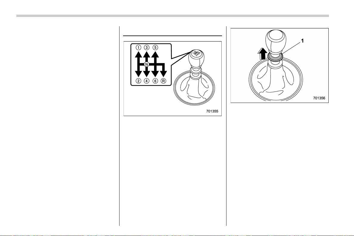
(378,1)
北米Model "A1700BE-B" EDITED: 2017/ 10/ 11
! System maintenance
Perform the procedure described in “Re-
placing battery of access key fob” F11-52.
Manual transmission
This manual transmission is a completely
synchromesh, 6-forward-speed and 1-re-
verse-speed transmission.
The shift pattern is shown on the shift lever
knob.
To change the shift lever position:
1. Depress the clutch pedal.
2. To shift into all positions other than “R”,
move the shift lever accordingly.
1) Slider
3. To shift into the “R” position, hold up the
slider, move the lever to the “R” position,
then release the slider.
4. Gradually release the clutch pedal.
If it is difficult to shift into gear, put the
transmission in neutral, release the clutch
pedal momentarily, and then try again.
Starting and operating/Manual transmission
7-16
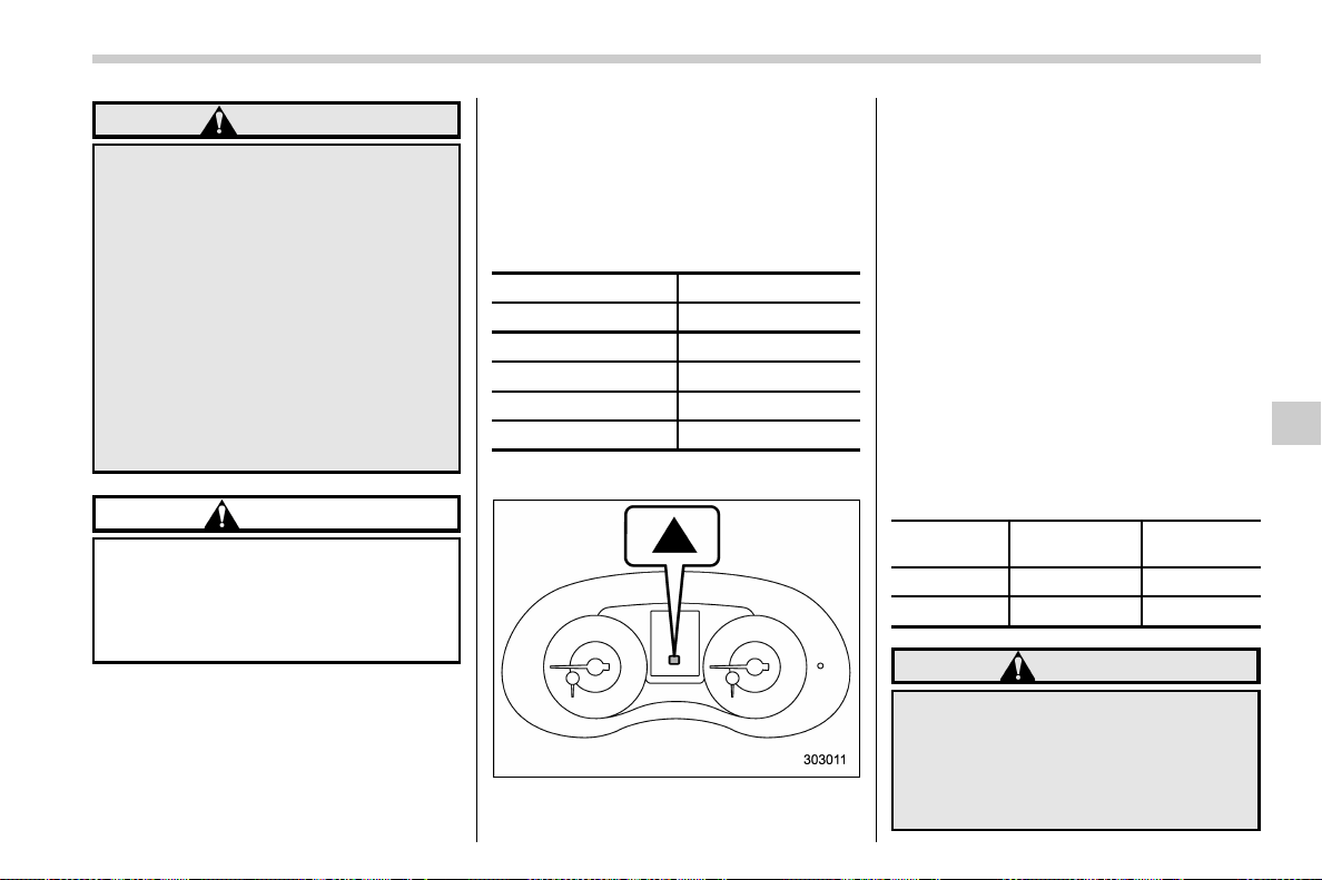
(379,1)
北米Model "A1700BE-B" EDITED: 2017/ 10/ 11
WARNING
. Do not drive the vehicle with the
clutch disengaged (i.e., when the
clutch pedal is depressed) or with
the shift lever in the neutral
position. Engine braking has no
effect in either of these condi-
tions and the risk of an accident
is consequently increased.
. Do not engage the clutch (i.e.,
release the clutch pedal) sud-
denly when starting the vehicle.
By doing so the vehicle might
unexpectedly accelerate or the
transmission could malfunction.
CAUTION
Shift into reverse ONLY when the
vehicle has completely stopped. It
may cause damage to the transmis-
sion to try shifting into reverse when
the vehicle is moving.
& Shifting speeds
! Recommended shifting speeds
The best compromise between fuel econ-
omy and vehicl e performance d uring
normal driving is ensured by shifting up
at the speeds listed in the following table.
Shift up mph (km/h)
1st to 2nd 15 (24)
2nd to 3rd 25 (40)
3rd to 4th 40 (64)
4th to 5th 45 (72)
5th to 6th
50 (80)
! Shift-up indicator (STI)
The shift-up indicator appears to inform
the driver about the upshift timing.
The shift-up indicator can be activated or
deactivated. For details, refer to “Gear
position indicator (MT models)/Shift -up
indicator (STI)” F3-34.
! Maximum allowable speeds
The following table shows the maximum
speeds that are possible with each differ-
ent gear. The tachometer’s needle will
enter the red area if these speeds are
exceeded.
With the exception of cases where sudden
acceleration is required, do not drive the
vehicle with the tachometer’s needle in-
side the red area. Failure to observe this
precaution can lead to excessive engine
wear and poor fuel economy.
Gear
STI
mph (km/h)
Except STI
mph (km/h)
1st 31 (50) 30 (49)
2nd 51 (82) 55 (88)
WARNING
When shifting down a gear, ensure
that the vehicle is not travelling at a
speed exceeding the Maximum Al-
lowable Speed for the gear which is
about to be selected. Failure to
observe this precaution can lead to
– CONTINUED –
Starting and operating/Manual transmission
7-17
7
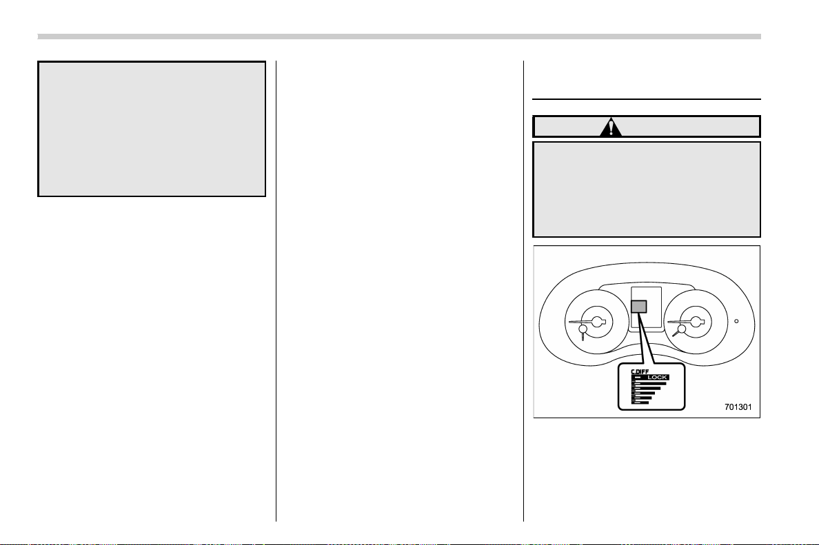
(380,1)
北米Model "A1700BE-B" EDITED: 2017/ 10/ 11
engine over-revving and this in turn
can result in engine damage.
In addition, sudden application of
engine brakes when the vehicle is
travelling on a slippery surface can
lead to wheel locking; as a conse-
quence, control of the vehicle may
be lost and the risk of an accident
increased.
NOTE
Never exceed the posted speed limit.
& Driving tips
NOTE
If the accelerator and brake pedals are
depressed at the same time, driving
torque may be restrained. This is not a
malfunction.
Do not drive with your foot resting on the
clutch pedal and do not use the clutch to
hold your vehicle at a standstill on an
upgrade. Either of those actions may
cause clutch damage.
Do not drive with your hand resting on the
shift lever. This may cause wear on the
transmission components.
When it is necessary to reduce vehicle
speed due to slow traffic, turning corners,
or driving up steep hills, downshift to a
lower gear before the engine starts to
labor.
On steep downgrades, downshift the
transmission to 5th, 4th, 3rd or 2nd gear
as necessary; this helps to maintain a safe
speed and to extend brake pad life.
In this way, the engine provides a braking
effect. Remember, if you “ride” (over use)
the brakes while descending a hill, they
may overheat and not work properly.
The engine may, on rare occasions, knock
when the vehicle rapidly accelerates or
rapidly pulls away from a standstill. This
phenomenon is not an indication of a
problem in your vehicle.
Driver’s Control Center Dif-
ferential (C.DIFF/DCCD) (STI)
WARNING
Always use the utmost care when
driving. Being overconfident be-
cause you are driving a vehicle with
a driver’s control center differential
could easily lead to a serious acci-
dent.
Starting and operating/Driver’s Control Center Differential (C.DIFF/DCCD) (STI)
7-18
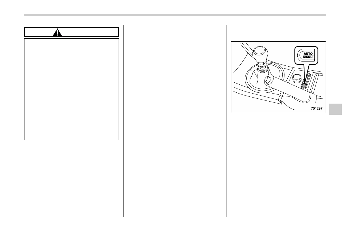
(381,1)
北米Model "A1700BE-B" EDITED: 2017/ 10/ 11
CAUTION
. All the indicators will flash in the
event that the driver’scontrol
center differential has a malfunc-
tion. Have the vehicle inspected
by your SUBARU dealer.
. If a malfunction occurs in the
vehicle (for example, when the
rear differential oil temperature
warning light illuminates), all of
the indicators may disappear and
the setting value for the initial
limited slip differential (LSD) tor-
que of the driver ’s control center
differential (C.DIFF/DCCD) may
be cancelled. However, it does
not indicate a malfunction of the
C.DIFF/DCCD itself.
The driver’s control cent er differen tial
allows you to freely change the degree of
limitation of the differential action (limited
slip differential (LSD) torque) of your
vehicle’s center differential.
By using the center differential control
switch, you can set an initial LSD torque
to match the road surface conditions,
driving conditions and your driving style.
The driver’s control center differential has
the following modes.
. Auto mode: the system automatically
adjusts the initial LSD torque.
. Manual mode: you can change to the
desired mode manually by using the
center differential control switch.
NOTE
If you rapidly depress and release the
accelerator pedal while driving at low
speed, you may hear a knocking sound
from the vicinity of the center differen-
tial and rear differential. This sound
occurs because of the structure of the
center differential. It does not indicate a
problem.
& To change mode of driver’s
control center differential
Press the “AUTO-MANU” switch on the
center console to switch from auto mode to
manual mode or vice versa. When you
select the auto mode, the “AUTO” indicator
appears. When you select the manual
mode, the “AUTO” indicator disappears.
– CONTINUED –
Starting and operating/Driver’s Control Center Differential (C.DIFF/DCCD) (STI)
7-19
7
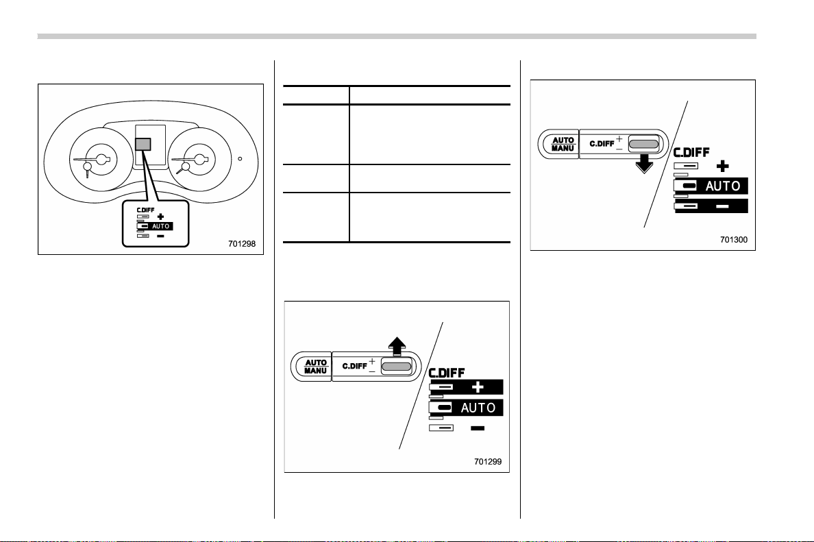
(382,1)
北米Model "A1700BE-B" EDITED: 2017/ 10/ 11
& Auto mode
In the auto mode, the system estimates the
driving and road conditions using signals
from the wheel speed sensor, throttle
position sensor, steering angle sensor
and brake switch, etc. According to the
result, it electronically and automatically
controls the degree of limitation of the
differential action (LSD torque) to optimize
the differential action of the center differ-
ential. When you turn the ignition switch
ON, the “AUTO” indicator on the combina-
tion meter appears.
The auto mode has 3 modes as follows.
Mode Operation
AUTO [+] This mode emphasizes traction
control and strengthens the lim-
itation of differential action that
is suitable for driving on slippery
roads for vehicle stability.
AUTO This mode is suitable for most
driving situations.
AUTO [−] This mode is suitable when you
seek quick response from the
steering wheel and smooth
driving.
! Mode setting method
In most situations, it is recommended that
the “AUTO” mode is selected.
Push the control switch forward to select
the “AUTO [+]” mode. After setting the
mode, “AUTO [+]” appears.
Pull the control switch rearward to select
the “AUTO [−]” mode. After setting the
mode, “AUTO [−]” appears.
When the “AUTO [+]” mode is selected,
pull the control switch rearward to change
to the “AUTO” mode. When the “AUTO [−]”
mode is set, push the control switch
forward to change to the “AUTO” mode.
Starting and operating/Driver’s Control Center Differential (C.DIFF/DCCD) (STI)
7-20
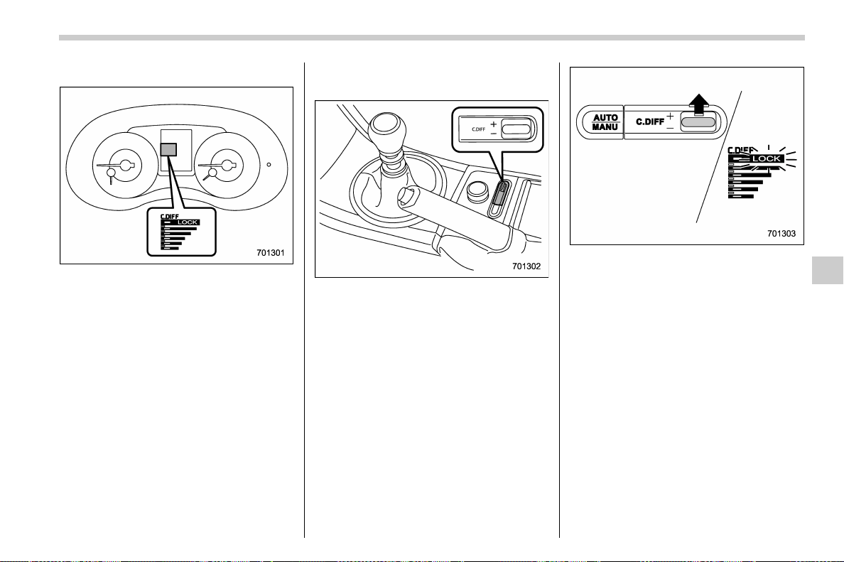
(383,1)
北米Model "A1700BE-B" EDITED: 2017/ 10/ 11
& Manual mode
In the manual mode, you can use the
center differential control switch to adjust
the initial LSD torque as desired. When
this mode is selected, the “AUTO” indica-
tor disappears.
! Center differential control switch
and indicator
The control switch is located beside the
parking brake lever. Push the control
switch forward or pull it rearward to change
the initial LSD torque.
The center differential indicator on the
combination meter gives six levels of
indication. The indicator and control switch
are linked; when operating the switch to
change the initial LSD torque, the indicator
changes accordingly.
Push the switch forward to increase the
initial LSD torque; when the “LOCK”
indicator appears, the initial LSD torque
setting is maximum. The center differential
will then be almost completely locked.
– CONTINUED –
Starting and operating/Driver’s Control Center Differential (C.DIFF/DCCD) (STI)
7-21
7
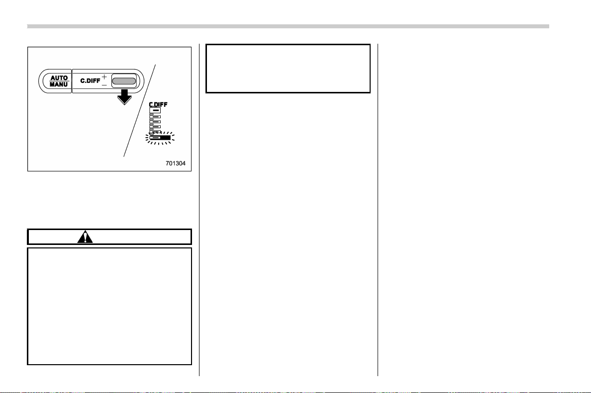
(384,1)
北米Model "A1700BE-B" EDITED: 2017/ 10/ 11
Pull the switch rearward to reduce the
initial LSD torque. When the lowest posi-
tion of the driver’s control center differen-
tial indicator is displayed, the initial LSD
torque will be minimum.
CAUTION
. Do not operate the control switch
when a wheel slippage occurs.
Wait until the wheelspin has been
brought under control.
. Under any of the following condi-
tions after setting to the manual
mode, pull the center differential
control switch to minimize the
initial LSD torque:
– When a temporary spare tire is
installed
– When your vehicle is towed
– When the vehicle is stopped
with the manual mode se-
lected
NOTE
. A higher initial LSD torque setting
gives the vehicle greater traction when
driving straight ahead but makes cor-
nering more difficult. Remember this
when adjusting the initial LSD torque.
In general, higher initial LSD torque
settings assist driving on slippery
roads and lower settings for non-slip-
pery roads. When the vehicle is stuck in
snow or mud, setting the initial LSD
torque to the maximum will help to free
the vehicle.
. The setting of the initial LSD torque
will remain even when the auto mode is
selected or the ignition switch is turned
to the “LOCK”/“OFF” position. How-
ever, the initial LSD torque will be
minimized when the battery is discon-
nected and reconnected.
. During cornering or when making
turns (especially when going into the
garage), the rotational difference be-
tween the front and rear wheels may
cause a braking effect accompanied by
vibration and noise. This does not
indicate a problem. The phenomenon
will disappear when setting the initial
LSD torque to the minimum.
In the auto mode, it controls the initial
LSD torque automatically. While in the
auto mode, this phenomenon some-
times occurs depending on the driving
condition, however, it does not indicate
a problem.
. Use the center differential indicator
only as a rough indication of the initial
LSD torque.
. If you operate the center differential
control switch while quickly accelerat-
ing or turning a tight corner, you may
feel slight shocks. This is due to
differential action by the center differ-
ential and does not indicate a problem.
& Temporary release
When the driver stops the vehicle and pulls
the parking brake lever after manually
setting the initial LSD torque, the LSD
torque is temporarily minimized. However
the indicator on the combination meter
continues to show the driver’s selected
initial LSD torque. When the driver re-
leases the parking brake lever, the initial
LSD torque set by the driver is restored.
Starting and operating/Driver’s Control Center Differential (C.DIFF/DCCD) (STI)
7-22
(385,1)
北米Model "A1700BE-B" EDITED: 2017/ 10/ 11
Continuously variable trans-
mission
The continuously variable transmission is
electronically controlled and provides an
infinite number of forward speeds and 1
reverse speed. It also has a manual mode.
WARNING
Do not shift from the “P” or “N”
position into the “D” or “R” position
while depressing the accelerator
pedal. This may cause the vehicle
to jump forward or backward.
CAUTION
. Observe the following precau-
tions. Otherwise, the transmis-
sion could be damaged.
– Shift into the “P ” or “R” posi-
tion only after the vehicle has
completely stopped.
– Do not shift from the “D”
position into the “R” position
or vice versa until the vehicle
has completely stopped.
. Do not race the engine for more
than 5 seconds in any position
except the “N” or “P” position
when the brake is applied or
when chocks are used in the
wheels. This may cause the
transmission fluid to overheat.
. Never move the vehicle as fol-
lows. Doing so may result in an
unexpected accident or malfunc-
tion.
– Moving rearward by inertia
with the select lever set in a
forward driving position.
– Moving forward by inertia with
the select lever set in the “R”
position.
. When parking the vehicle, first
securely apply the parking brake
and then place the select lever in
the “P” position. Do not park for a
long time with the select lever in
any other position as doing so
could result in a dead battery.
NOTE
. When the engine coolant tempera-
ture is still low, the transmission will
upshift to higher engine speeds than
when the coolant temperature is suffi-
ciently high in order to shorten the
warm-up time and improve driveability.
The gearshift timing will automatically
shift to the normal timing after the
engine has warmed up.
. Immediately after transmission fluid
is replaced, you may feel that the
transmission operation is somewhat
unusual. This results from invalidation
of data which the on-board computer
has collected and stored in memory to
allow the transmission to shift at the
most appropriate times for the current
condition of your vehicle. Optimized
shifting will be restored as the vehicle
continues to be driven for a while.
. When driving under continuous hea-
vy load conditions such as when climb-
ing a long, steep hill, the engine speed
or the vehicle speed may automatically
be reduced. This is not a malfunction.
This phenomenon results from the
engine control function maintaining
the cooling performance of the vehicle.
The engine and vehicle speed will
return to a normal speed when the
engine is able to maintain the optimum
cooling performance after the heavy
load decreases. Take extremely care
when driving under a heavy load.
. The continuously variable transmis-
sion is a chain type system that pro-
vides superior transmission efficiency
for maximum fuel economy. At times,
depending on varying driving condi-
tions, a chain operating noise may be
– CONTINUED –
Starting and operating/Continuously variable transmission
7-23
7
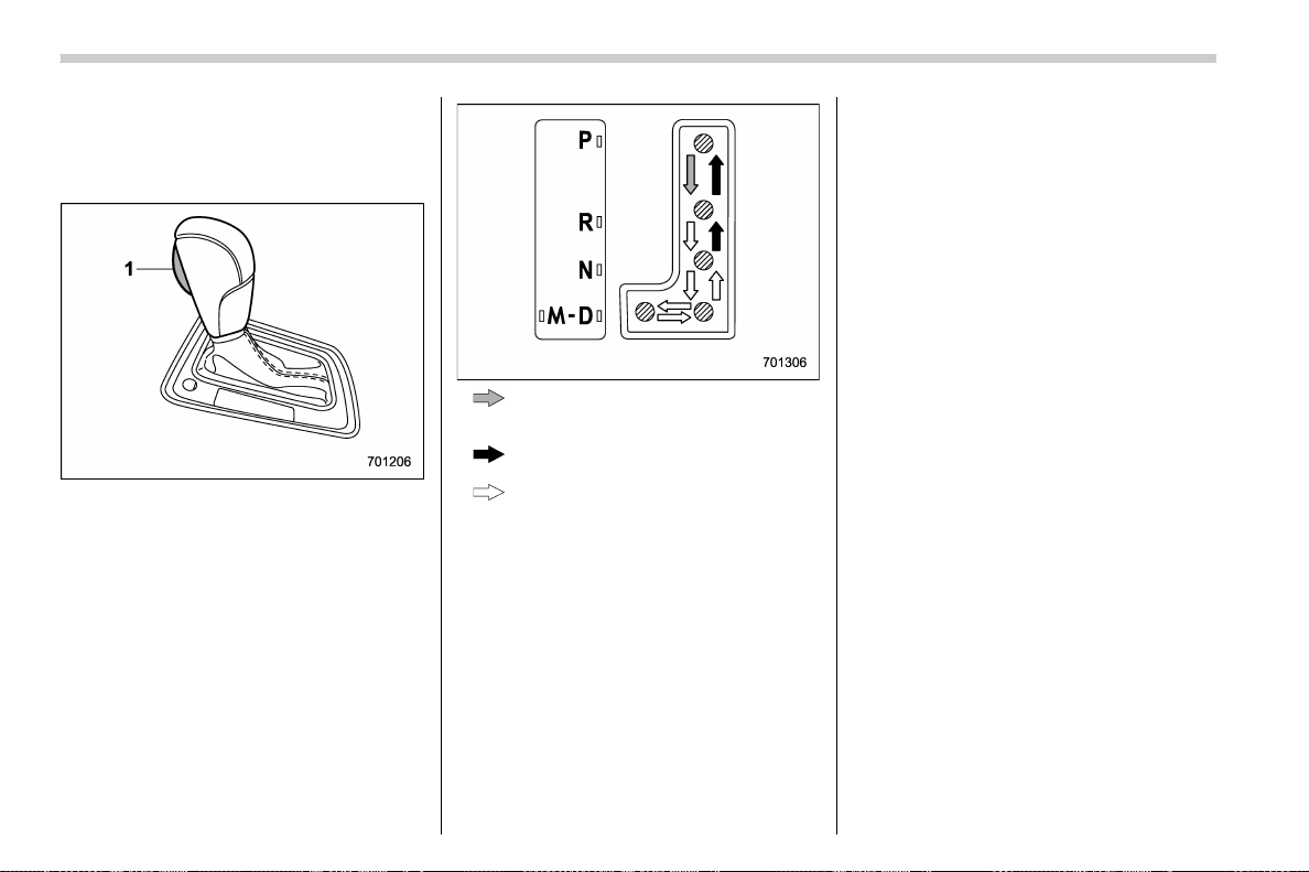
(386,1)
北米Model "A1700BE-B" EDITED: 2017/ 10/ 11
heard that is characteristic of this type
of system.
& Select lever
1) Select lever button
: With the brake pedal depressed, shift
while pressing the select lever button
in.
: Shift while pressing the select lever
button in.
: Shift without pressing the select lever
button.
The select lever has four positions, “P”,
“R”, “N”, “D” and it also has an “M” position
for using the manual mode.
NOTE
For some models, to protect the engine
while the select lever is in the “P” or “N”
position, the engine is controlled so
that the engine speed may not become
too high even if the accelerator pedal is
depressed hard.
! P (Park)
This position is for parking the vehicle and
starting the engine. In this position, the
transmission is mechanically locked to
prevent the vehicle from rolling freely.
When you park the vehicle, first apply the
parking brake firmly, then shift into the “P”
position. Do not hold the vehicle with only
the mechanical friction of the transmission.
To shift the select lever from the “P”
position to any other position, you should
depress the brake pedal fully then move
the select lever. This prevents the vehicle
from lurching when it is started.
! R (Reverse)
This position is for backing the vehicle. To
shift from the “N” to “R” position, stop the
vehicle completely then move the lever to
the “R” position while pressing the select
lever button in.
Even when you have turned the ignition
switch to the “LOCK”/“OFF” position, you
can still move the select lever from the “N”
to “R” position for a limited time period by
depressing the brake pedal, and then it
becomes impossible. For details, refer to
“Shift lock function” F7-27.
Starting and operating/Continuously variable transmission
7-24
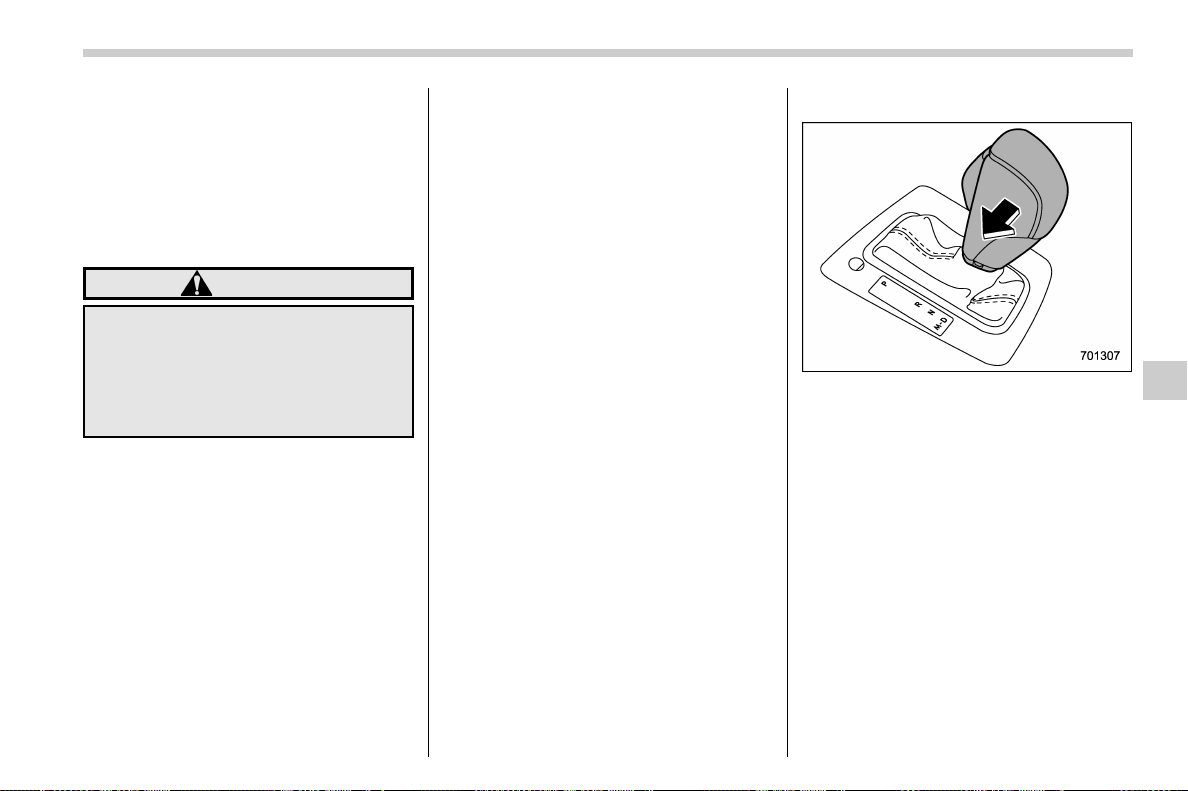
(387,1)
北米Model "A1700BE-B" EDITED: 2017/ 10/ 11
! N (Neutral)
This position is for restarting a stalled
engine. In this position, the transmission is
neutral, meaning that the wheels and
transmission are not locked. Therefore,
the vehicle will roll freely, even on the
slightest incline unless the parking brake
or foot brake is applied.
WARNING
Do not drive the vehicle with the
select lever in the “N” (neutral)
position. Engine braking has no
effect in this condition and the risk
of an accident is consequently in-
creased.
NOTE
If the select lever is in the “N” position
when you stop the engine for parking,
you may not subsequently be able to
move it to the “R” and “P” positions. If
this happens, turn the ignition switch to
the “ON” position. You will then be able
to move the select lever to the “P”
position.
! D (Drive)
This position is for normal driving. The
transmission shifts automatically and con-
tinuously into a suitable gear according to
the vehicle speed and the acceleration you
require. Also, while driving up and down a
hill, the transmission assists and controls
the driving performance and engine brak-
ing while corresponding to the road grade.
When more acceleration is required in the
“D” position, depress the accelerator pedal
fully to the floor and hold that position. The
transmission will automatically downshift.
If the Intelligent (I) mode or the Sport (S)
mode has been selected, the transmission
will operate like a conventional automatic
transmission. When you release the pedal,
the transmission will return to the original
gear position.
If you operate one of the shift paddles
behind the steering wheel while driving in
the “D” position, the t ransmission will
temporarily switch to the manual mode.
In this mode, you can shift into any gear
position using the shift paddles. For details
about the manual mode, refer to “Selection
of manual mode” F7-25. Once the vehicle
speed stabilizes, the transmission will
switch from the manual mode back to the
“D” position for normal driving.
& Selection of manual mode
With the vehicle either moving or station-
ary, move the select lever from the “D”
position to the “M” position to select the
manual mode.
– CONTINUED –
Starting and operating/Continuously variable transmission
7-25
7

(388,1)
北米Model "A1700BE-B" EDITED: 2017/ 10/ 11
1) Upshift indicator
2) Downshift indicator
3) Gear position indicator
When the manual mode is selected, the
gear position indicator and upshift indica-
tor and/or downshift indicator on the
combination meter appear.
The gear position indicator shows the
currently selected gear in the following
range.
. 1st-to-8th-gear range (when the Sport
Sharp (S#) mode is selected)
. 1st-to-6th-gear range (in other situa-
tions)
The upshift and downshift indicators show
when a gear shift is possible. When the
upshift indicator “
” appears, upshifting is
possible. When the downshift indicator
“
” appears, downshifting is possible.
When both indicators appear, upshifting
and downshifting are both possible. When
the vehicle stops (for example, at traffic
signals), the downshift indicator turns off.
Gearshifts can be performed using the
shift paddle behind the steering wheel.
To upshift to the next higher gear position,
pull the shift paddle that has “+” indicated
on it. To downshift to the next lower gear
position, pull the shift paddle that has “–”
indicated on it.
CAUTION
Do not place or hang anything on the
shift paddles. Doing so may result in
accidental gear shifting.
NOTE
Please read the following points care-
fully and bear them in mind when using
the manual mode.
. If you attempt to shift down when the
engine speed is too high, i.e., when a
downshift would push the tachometer
needle beyond the red zone, beeps will
be emitted to warn you that the down-
shift is not possible.
. If you attempt to shift up when the
vehicle speed is too low, the transmis-
sion will not respond.
. You can perform a skip-shift (for
example, from 4th to 2nd) by operating
the shift paddle twice in rapid succes-
sion.
. The transmission automatically se-
lects 1st gear when the vehicle stops
moving.
. If the temperature of the transmis-
sion fluid becomes too high, the “AT
OIL TEMP” warning light on the combi-
nation meter will illuminate. Immedi-
ately stop the vehicle in a safe location
and let the engine idle until the warning
light turns off.
. By selecting the Sport Sharp (S#)
mode, upshifting will not occur auto-
matically. According to the road condi-
tions, shift change manually so that the
tachometer needle does not enter the
Starting and operating/Continuously variable transmission
7-26
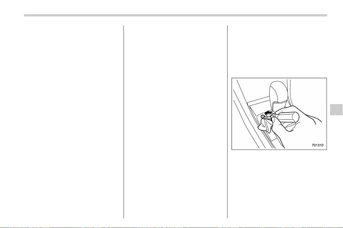
(389,1)
北米Model "A1700BE-B" EDITED: 2017/ 10/ 11
red zone. Also, if the engine revolutions
reach the specified number, the fuel
supply will be cut. In this case, perform
shift up operation.
! To deselect the manual mode
To deselect the manual mode, return the
select lever to the “D” position from the “M”
position.
& Shift lock function
The shift lock function helps prevent the
improper operation of the select lever.
. You cannot move the select lever with
the ignition switch in the “ON” position and
the brake pedal depressed.
. You cannot move the select lever from
the “P” position to any other position
unless the brake pedal is depressed.
Depress the brake pedal first, and then
operate the select lever.
. Only the “P” position allows you to turn
the ignition switch from the “ACC” position
to the “LOCK”/“OFF” position and remove
the key from the ignition switch.
. If you turn the ignition switch to the
“LOCK”/“OFF” position while the select
lever is in the “N” position, the select lever
may not be moved to the “P” position after
a period of time. Therefore, move the
select lever to the “P” position with the
brake pedal depressed soon after turning
the ignition switch to the “LOCK”/“OFF”
position.
! Shift lock release
If you cannot move the select lever, turn
theignitionswitchbacktothe“ON”
position then move the select lever to the
“P” position with the select lever button
pressed and brake pedal depressed.
If the select lever does not move after
performing the above procedure, perform
the following steps.
. When you cannot shift the select
lever from “P” to “N”:
Refer to “
Shift lock release using the shift
lock release button” F7-27.
. When you cannot shift the select
lever from “N” to “R”, “P”:
Within 60 seconds after placing the ignition
switch in the “ACC” position, move the
select lever to the “P” position with the
select lever button pre ssed and brake
pedal depressed.
If you must perform the above procedure,
the shift lock system (or the vehicle control
system) may be malfunctioning. Contact a
SUBARU dealer for an inspection as soon
as possible.
If the select lever does not move after
performing the above procedure, refer to
“Shift lock release using the shift lock
release button” F7-27.
! Shift lock release using the shift
lock release button
Perform the following procedure to release
the shift lock.
1. Apply the parking brake and stop the
engine.
2. Wrap the tip of a flat-head screwdriver
with vinyl tape or a cloth and use it to
remove the shift lock cover. The shift lock
release button is located under the shift
lock cover.
– CONTINUED –
Starting and operating/Continuously variable transmission
7-27
7
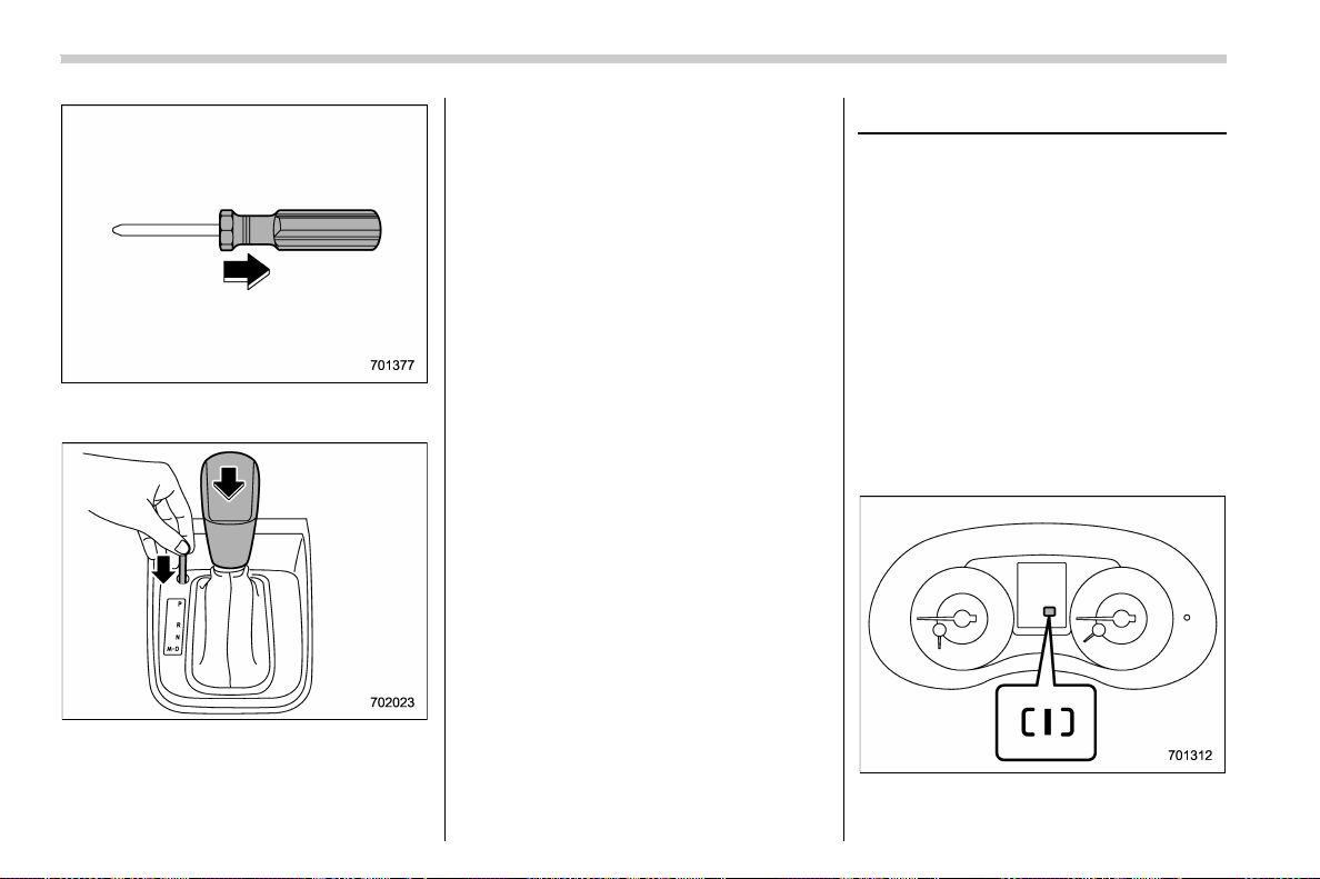
(390,1)
北米Model "A1700BE-B" EDITED: 2017/ 10/ 11
3. Remove the grip portion of the screw-
driver.
4. While depressing the brake pedal,
insert a screwdriver into the hole, press
the shift lock release button using a
screwdriver, and then move the select
lever.
If the select lever does not move after
performing the above procedure, the shift
lock system may be malfunctioning. Con-
tact a SUBARU dealer for an inspection as
soon as possible.
& Driving tips
NOTE
If the accelerator and brake pedals are
depressed at the same time, driving
torque may be restrained. This is not a
malfunction.
. Always apply the foot or parking brake
when the vehicle is stopped in the “D” or
“R” position.
. Make sure to apply the parking brake
when parking your vehicle. Do not hold the
vehicle with only the mechanical friction of
the transmission.
. Do not keep the vehicle in a stationary
position on an uphill grade by using the “D”
position. Use the brake instead.
. The engine may, on rare occasions,
knock when the vehicle rapidly acceler-
ates or rapidly pulls away from a standstill.
This phenomenon does not indicate a
malfunction.
SI-DRIVE (if equipped)
SI-DRIVE (SUBARU Intelligent Drive)
works to maximize engine performance,
control and efficiency.
This system consists of three modes:
. Intelligent (I) mode
. Sport (S) mode
. Sport Sharp (S#) mode
By adjusting the SI-DRIVE selector, the
character of the power unit changes.
& Intelligent (I) mode
! For smooth, efficient performance
driving
The Intelligent (I) mode provides well-
balanced performance with greater fuel
Starting and operating/SI-DRIVE
7-28
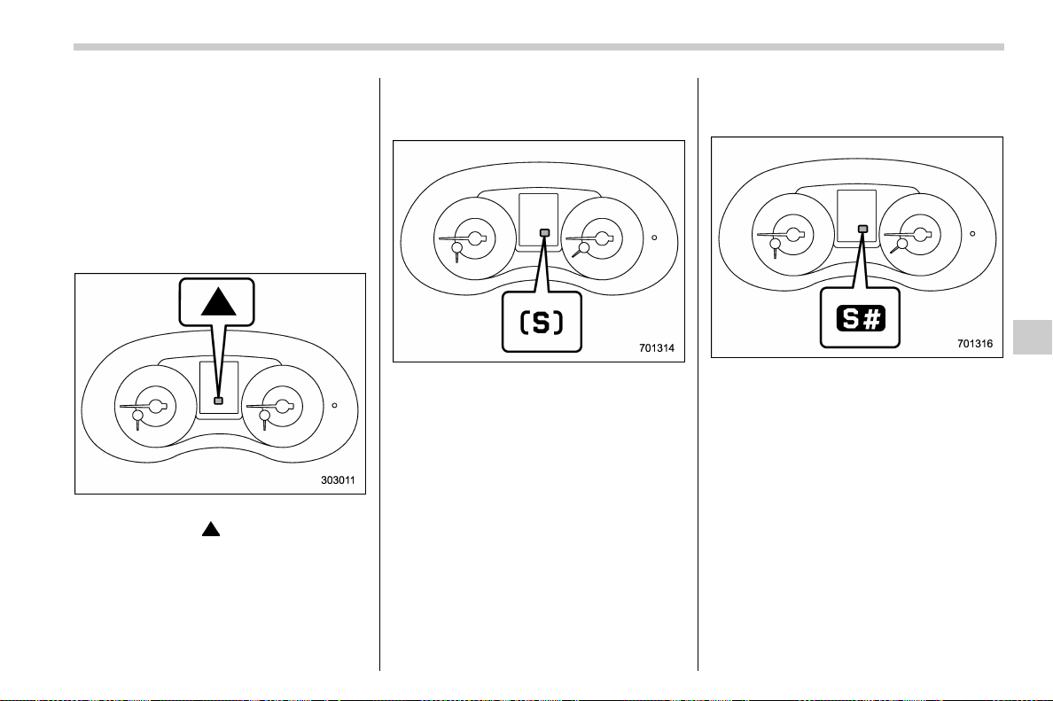
(391,1)
北米Model "A1700BE-B" EDITED: 2017/ 10/ 11
efficiency and smooth driveability without
stress. Power delivery is moderate during
acceleration for maximum fuel efficiency.
This is ideal for around-town driving and
situations that do not require full power
output. It provides better control in difficult
driving conditions, such as slippery roads
or loose surfaces, due to gentler throttle
response.
STI:
When the Intelligent (I) mode is selected, a
shift-up indicator “
” on the combination
meter will blink to signal the best time to
shift gears for maximum fuel efficiency.
Except STI:
The linear acceleration characteristic of
the Intelligent (I) mode is ideal for normal
driving.
& Sport (S) mode
! For all-around performance driving
The Sport (S) mode provides the engine
power desired by those who want to make
the driving experience their own personal
adventure.
STI:
The linear acceleration characteristic of
the Sport (S) mode is ideal for normal
driving.
& Sport Sharp (S#) mode
! For maximum performance driving
For sports-minded drivers, the Sport
Sharp (S#) mode offers an exhilarating
level of engine performance and control.
The throttle becomes more responsive
regardless of the engine speed. Delivering
maximum driving enjoyment, this mode is
ideal for driving on twisting roads and for
merging or overtaking other vehicles on
the freeway with confidence.
– CONTINUED –
Starting and operating/SI-DRIVE
7-29
7
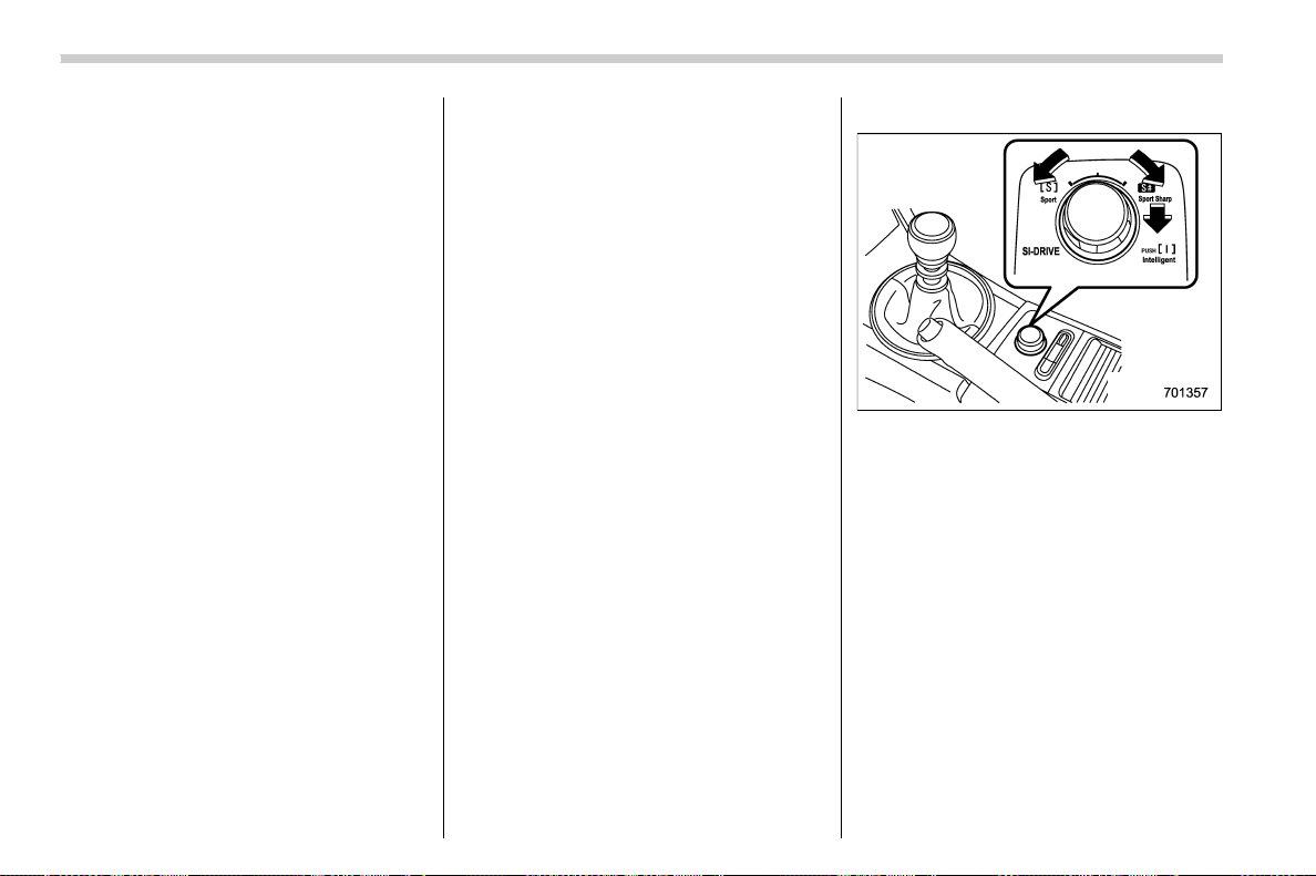
(392,1)
北米Model "A1700BE-B" EDITED: 2017/ 10/ 11
! Except STI
When you select the Sport Sharp (S#)
mode with the select lever in the “D”
position, the transmission gear ratio will
shift from variable speed to eight-speed.
The select lever/gear position indicator
display will change from “D” to the gear
position.
When selecting Sport Sharp (S#) mode,
the following controls will be applied.
. Uphill control
Prevents unnecessary shift-up/shift-down
during ascent.
. Cornering control
While turning, if there is a large centrifugal
force, shift-up will not occur: during re-
acceleration.
. Braking control
At the beginning of corners etc., heavy
application of the brake pedal will cause
automatic downshift and gently re-accel-
erate.
. Sudden acceleration return control
During acceleration, if acceleration pedal
is returned suddenly (for example, at
corners etc.), shift-up will not be applied.
& SI-DRIVE switch
NOTE
. The next time you turn on the engine,
the following SI-DRIVE mode will be
selected.
– Intelligent (I) mode if you have
turned off the engine in the Intelli-
gent (I) mode
– Sport (S) mode if you have turned
off the engine in the Sport (S) mode
or Sport Sharp (S#) mode
. If the CHECK ENGINE warning light/
malfunction indicator light illuminates
during engine operation, the SI-DRIVE
mode changes to the Sport (S) mode. In
this case, it is not possible to change to
the Sport Sharp (S#) mode or Intelligent
(I) mode.
. If the engine coolant temperature
becomes so high that the engine could
overheat, it is not possible to change to
the Sport Sharp (S#) mode. While the
vehicle is in the Sport Sharp (S#) mode,
it changes to the Sport (S) mode when
the engine coolant temperature in-
creases.
. If any of the SI-DRIVE indicators
blink, the SI-DRIVE s yste m may be
malfunctioning. Contact your SUBARU
dealer.
! STI
SI-DRIVE switch
To select the Intelligent (I) mode:
Push the SI-DRIVE switch.
To select the Sport (S) mode:
Rotate the SI-DRIVE switch to the left.
To select the Sport Sharp (S#) mode:
Rotate the SI-DRIVE switch to the right.
After operating the SI-DRIVE switch, the
switch returns to its original position.
Starting and operating/SI-DRIVE
7-30
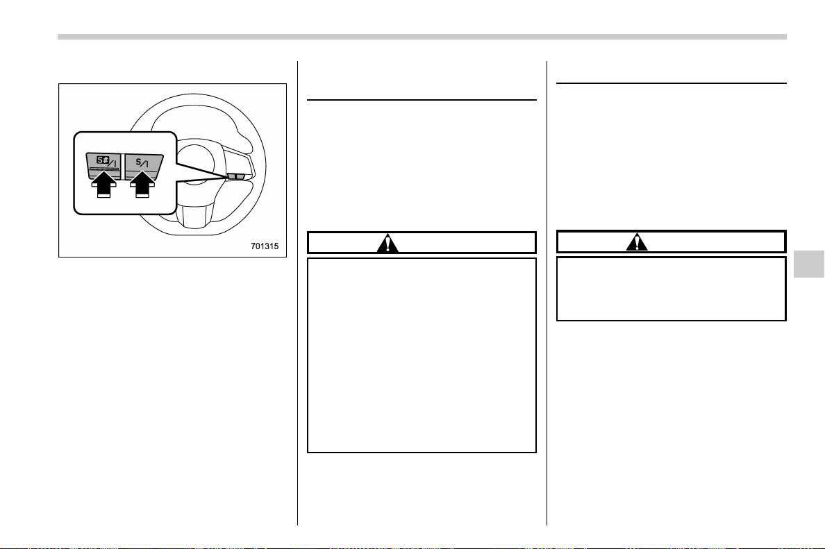
(393,1)
北米Model "A1700BE-B" EDITED: 2017/ 10/ 11
! Except STI
SI-DRIVE switches
To select the Intelligent (I) mode:
. Press the “S/I” switch when the Sport
(S) mode is selected
. Press the “S#/I” switch when the Sport
Sharp (S#) mode is selected
To select the Sport (S) mode:
Press the “S/I” switch when any mode
other than Sport (S) mode is selected.
To select the Sport Sharp (S#) mode:
Press the “S#/I” switch when any mode
other than Sport Sharp (S#) mode is
selected.
Limited slip differential (LSD)
(STI)
The LSD provides optimum distribution of
power according to the difference in
revolutions between the right and left
wheels that may be caused by certain
driving conditions, thereby improving driv-
ing stability on snow-covered, muddy or
other slippery roads or when high speed
driving.
CAUTION
. Never start the engine while a tire
on one side is jacked up, as the
vehicle may move.
. If one tire is spinning in mud,
avoid continued spinning at high
speed as this could adversely
affect the LSD.
. If you use a temporary spare tire
to replace a flat tire, be sure to
use the original temporary spare
tire stored in the vehicle. Using
other sizes will adversely affect
the LSD.
Power steering
& STI
The vehicle is equipped with a hydraulic
power steering system. The power steer-
ing system operates only when the engine
is running.
If you lose power steering assist because
the engine stops or the system fails to
function, you can steer but it will take much
more effort.
CAUTION
Do not hold the steering wheel at the
fully locked position left or right for
more than 5 seconds. This may
damage the power steering pump.
NOTE
Right after the engine has been started
and before it has warmed up, you may
hear a noise coming from areas adja-
cent to the power steering pump which
is located at the right-front area of the
engine compartment. This noise is
normal. It does not in dicate power
steering system trouble.
– CONTINUED –
Starting and operating/Limited slip differential (LSD) (STI)
7-31
7

(394,1)
北米Model "A1700BE-B" EDITED: 2017/ 10/ 11
& Except STI
Power steering warning light
The vehicle is equipped with an electric
power steering system. The power steer-
ing system operates only while the engine
is running. When you turn the ignition
switch to the “ON” position, the power
steering warning light on the combination
meter illuminates to inform the driver that
the warning system is functioning properly.
Then, if the engine started, the warning
light turns off to inform the driver that the
steering power assist is operational.
CAUTION
While the power steering warning
light is illuminated, there may be
more resistance when the steering
wheel is operated. Drive carefully to
the nearest SUBARU dealer and
have the vehicle inspected immedi-
ately.
NOTE
If you operate the steering wheel in the
following ways, the power steering
control system may temporarily limit
the power assist in order to prevent the
system components, such as the con-
trol computer and drive motor, from
overheating.
. You operate the steering wheel fre-
quently and turn it sharply while the
vehicle is maneuvered at extremely low
speeds, such as while frequently turn-
ing the steering wheel during parallel
parking.
. You keep the steering wheel in the
fully turned position for a long period of
time.
At this time, there will be more resis-
tance when steering. However this is
not a malfunction. Normal steering
force will be restored after the steering
wheel is not operated for a while and
the power steering control system has
an opportunity to cool down. However,
if the power steering is operated in a
non-standard way which causes power
assist limitation to occur too frequently,
this may result in a malfunction of the
power steering control system.
Starting and operating/Power steering
7-32
(395,1)
北米Model "A1700BE-B" EDITED: 2017/ 10/ 11
Braking
& Braking tips
WARNING
Never rest your foot on the brake
pedal while driving. This can cause
dangerous overheating of the
brakes and needless wear on the
brake pads and linings.
! When the brakes get wet
When driving in rain or after washing the
vehicle, the brakes may get wet. As a
result, brake stopping distance will be
longer. To dry the brakes, drive the vehicle
at a safe speed while lightly depressing the
brake pedal to heat up the brakes.
! Use of engine braking
Remember to make use of engine braking
in addition to foot braking. When descend-
ing a grade, if only the foot brake is used,
the brakes may start working improperly
because of brake fluid overheating,
caused by overheated brake pads. To help
prevent this, shift into a lower gear to get
stronger engine braking.
! Braking when a tire is punctured
Do not depress the brake pedal suddenly
when a tire is punctured. This could cause
a loss of control of the vehicle. Keep
driving straight ahead while gradually
reducing speed. Then slowly pull off the
road to a safe place.
& Brake system
! Two separate circuits
Your vehicle has two separate circuit brake
systems. Each circuit works diagonally
across the vehicle. If one circuit of the
brake system should fail, the other half of
the system still works. If one circuit fails,
the brake pedal will go down much closer
to the floor than usual and you will need to
press it down much harder. And a much
longer distance will be needed to stop the
vehicle.
! Brake booster
The brake booster uses engine manifold
vacuum to assist braking force. Do not turn
off the engine while driving because that
will turn off the brake booster, resulting in
poor braking power.
The brakes will continue to work even
when the brake booster completely stops
functioning. If this happens, however, you
will have to depress the pedal much harder
than normal and the braking distance will
increase.
! Brake assist system
WARNING
Do not be overconfident about the
brake assist. It is not a system that
brings more braking ability to the
vehicle beyond its braking capabil-
ity. Always use the utmost care
when driving regarding vehicle
speed and safe distance.
CAUTION
When you need to brake suddenly,
continue depressing the brake pedal
strongly to obtain the effect of the
brake assist.
Brake assist is a driver assistance system.
It assists the brake power when the driver
cannot depress the brake pedal strongly
and the brake power is insufficient.
Brake assist generates the brake power
according to the speed at which the driver
depresses the brake pedal.
NOTE
When you depress the brake pedal
strongly or suddenly, the following
phenomena occur. However, even
though these occur, they do not indi-
– CONTINUED –
Starting and operating/Braking
7-33
7
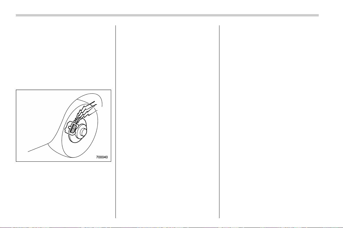
(396,1)
北米Model "A1700BE-B" EDITED: 2017/ 10/ 11
cate any malfunctions, and the brake
assist system is operating properly.
. You might feel that the brake pedal is
applied by lighter force and generates a
greater braking force.
. You might hear an ABS operating
noise from the engine compartment.
& Disc brake pad wear warning
indicators
The disc brake pad wear warning indica-
tors on the disc brakes give a warning
noise when the brake pads are worn.
If a squeaking or scraping noise is heard
from the disc brakes while braking, im-
mediately have your vehicle checked by
your SUBARU dealer.
& High performance brake sys-
tem (STI)
Your vehicle is equipped with large, high
performance brake pads that provide
optimum braking force under various driv-
ing conditions. The brake pads have the
following characteristics.
Brake noises
The brake pads are made of iron-based
material. Therefore, unusual noise may be
heard when depressing the brake pedal
slightly before stopping completely. How-
ever, this does not indicate a malfunction.
Discoloration
Frequent severe driving, such as repeated
driving on sharp uphill or downhill grades,
can cause discoloration of the paint on the
brake calipers. The discoloration will not
affect the braking performance.
Stuck brake pads
. If the vehicle is left parked for an
extended period of time with the brake
system wet, the iron in the brake pads may
form rust and cause the brake pads and
disc rotors to stick together. This may
result in noise or vibration while driving. If
this occurs, fully depress the brake pedal
several times to free the brake pads.
. If the vehicle is left parked for an
extended period of time in a cold tempera-
ture, the brake pads and disc rotors may
be frozen and stuck together. In this case,
it may be difficult to start the vehicle.
Brake dust
Due to the material used for the brake
pads, the wheels may become covered in
brake dust. This is not a malfunction, and
will not affect the brake performance.
& Red caliper with sports brake
pad (if equipped)
Brake noises
The brake pads are made of iron-based
material. Therefore, unusual noise may be
heard when depressing the brake pedal
slightly before stopping completely. How-
ever, this does not indicate a malfunction.
Brake dust
Due to the material used for the brake
pads, the wheels may become covered in
brake dust. This is not a malfunction, and
will not affect the brake performance.
Starting and operating/Braking
7-34
(397,1)
北米Model "A1700BE-B" EDITED: 2017/ 10/ 11
ABS (Anti-lock Brake Sys-
tem)
The ABS prevents the lock-up of wheels
which may occur during sudden braking or
braking on slippery road surfaces. This
helps prevent the loss of steering control
and directional stability caused by wheel
lock-up.
When the ABS is operating, you may hear
a chattering noise or feel a slight vibration
in the brake pedal. This is normal when the
ABS operates.
The ABS will not operate when the vehicle
speed is below approximately 6 mph (10
km/h).
WARNING
Always use the utmost care in driv-
ing – overconfidence because you
are driving a vehicle with the ABS
could easily lead to a serious acci-
dent.
CAUTION
. The ABS does not always de-
crease stopping distance. You
should always maintain a safe
following distance from other
vehicles.
. When driving on badly surfaced
roads, gravel roads, icy roads, or
over deep newly fallen snow,
stopping distances may be long-
er for a vehicle with the ABS than
one without. When driving under
these conditions, therefore, re-
duce your speed and leave ample
distance from other vehicles.
. When you feel the ABS operating,
you should maintai n constan t
brake pedal p ressure. Do not
pump the brake pedal since
doing so may defeat the opera-
tion of the ABS system.
& ABS self-check
Just after the vehicle is started, you may
feel on the brake pedal a vibration similar
to when the ABS operates, and you may
also hear the sound of the ABS working
from t he engine compartment. This is
caused by an automatic functional test of
the ABS being carried out and does not
indicate any abnormal condition.
& ABS warning light
Refer to “ABS warning light” F3-20.
Starting and operating/ABS (Anti-lock Brake System)
7-35
7
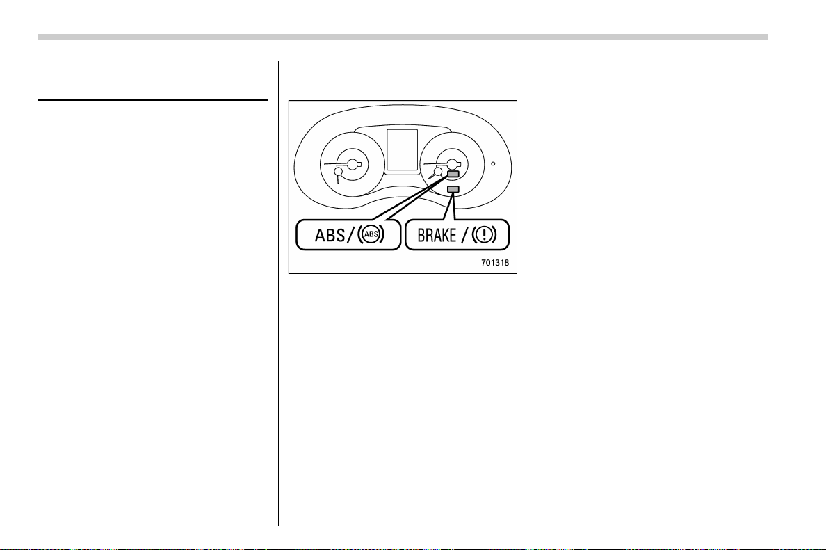
(398,1)
北米Model "A1700BE-B" EDITED: 2017/ 10/ 11
Electronic Brake Force Dis-
tribution (EBD) system
The EBD system maximizes the effective-
ness of the brakes by allowing the rear
brakes to supply a greater proportion of the
braking force. It functions by adjusting the
distribution of braking force to the rear
wheels in accordance with the vehicle’s
loading condition and speed.
The EBD system is an integral part of the
ABS and uses some of the ABS compo-
nents to perform its function of optimizing
the distribution of braking force. If any of
the ABS components used by the EBD
system malfunction, the EBD system also
stops working.
When the EBD system is operating, you
may hear a chattering noise or feel a slight
vibration in the brake pedal. This is normal
and does not indicate a malfunction.
& Steps to take if EBD system
malfunctions
Brake and ABS warning light
If a malfunction occurs in the EBD system,
the system stops working and the brake
system warning light and ABS warning
light illuminate simultaneously.
The EBD system may be malfunctioning if
the brake system warning light and ABS
warning light illuminate simultaneously
while driving.
Even if the EBD system malfunctions, the
conventional braking system will still func-
tion. However, the rear wheels will be more
prone to locking when the brakes are
applied harder than usual and the vehicle’s
motion may therefore become somewhat
harder to control.
If the brake system warning light and ABS
warning light illuminate simultaneously,
take the following steps.
1. Stop the vehicle in the nearest safe, flat
location.
2. Apply the parking brake and turn off the
engine.
3. Restart the engine.
4. Release the parking brake.
Even if both warning lights turn off:
The EBD system may be malfunctioning.
Drive carefully to the nearest SUBARU
dealer and have the system inspected.
If both warning lights illuminate again
and remain illuminated after restarting
the engine:
1. Turn off the engine again.
2. Apply the parking brake.
3. Check the brake fluid level. For details
about checking the brake fluid level, refer
to “Checking the fluid level” F11-24.
. If the brake fluid level is not below the
“MIN” mark, the EBD system may be
malfunctioning. Drive carefull y to the
nearest SUBARU dealer and have the
system inspected.
. If the brake fluid level is below the “MIN”
mark, DO NOT drive the vehicle. Instead,
have the vehicle towed to the nearest
Starting and operating/Electronic Brake Force Distribution (EBD) system
7-36
(399,1)
北米Model "A1700BE-B" EDITED: 2017/ 10/ 11
SUBARU dealer for repair.
WARNING
. Driving with the brake system
warning light illuminated is dan-
gerous. This indicates your brake
system may not be working prop-
erly. If the light remains illumi-
nated, have the brakes inspected
by a SUBARU dealer immedi-
ately.
. If at all in doubt about whether the
brakes are operating properly, do
not drive the vehicle. Have your
vehicle towed to t he nearest
SUBARU dealer for repair.
Vehicle Dynamics Control
system
WARNING
Always use the utmost care in driv-
ing – overconfidence because you
are driving a vehicle with the Vehicle
Dynamics Control system could ea-
sily lead to a serious accident.
CAUTION
. Even if your vehicle is equipped
with Vehicle Dynamics Control
system, winter tires should be
used when driving on snow-cov-
ered or icy roads; in addition,
vehicle speed should be reduced
considerably. Simply having a
Vehicle Dynamics Control sys-
tem does not guarantee that the
vehicle will be able to avoid
accidents in any situation.
. Activation of the Vehicle Dy-
namics Control system is an
indication that the road being
travelled on has a slippery sur-
face; since having Vehicle Dy-
namics Control is no guarantee
that full vehicle control will be
maintained at all times and under
all conditions, its activation
should be seen as a sign that
the speed of the vehicle should
be reduced considerably.
. Whenev er suspension compo-
nents, steering components, or
an axle are removed from a
vehicle, have an inspecti on of
that system performed by an
authorized SUBARU dealer.
. Observe the following precau-
tions in order to ensure that the
Vehicle Dynamics Control sys-
tem is operating properly:
– Fit all four wheels with tires of
the same size, type, and
brand. Furthermore, the
amount of wear should be the
same for all four tires.
– Keep the tire pressure at the
proper level as shown on the
vehicle placard attached to
the driver’s side door pillar.
– Use only the specified tempor-
ary spare tire to replace a flat
tire. With a temporary spare
tire, the effectiveness of the
Vehicle Dynamics Control
system is reduced and this
– CONTINUED –
Starting and operating/Vehicle Dynamics Control system
7-37
7
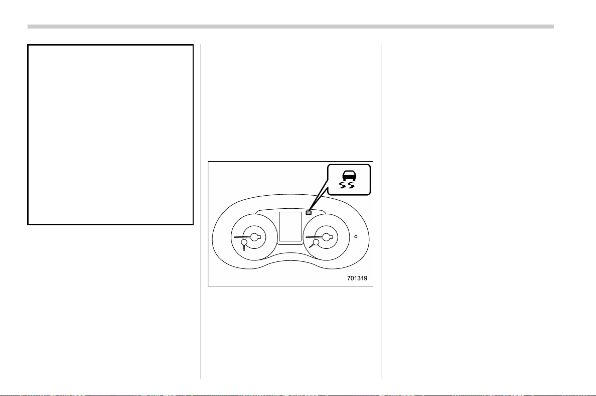
(400,1)
北米Model "A1700BE-B" EDITED: 2017/ 10/ 11
should be taken into account
when driving the vehicle in
such a condition.
. If you use non-matching tires, the
Vehicle Dynamics Control sys-
tem may not operate correctly.
. The Vehicle Dynamics Control
system helps prevent unstable
vehicle motion such as skidding
using control of the brakes and
engine power. Do not turn off the
Vehicle Dynamics Control sys-
tem unless it is absolutely neces-
sary. If you must turn off the
Vehicle Dynamics Control sys-
tem, drive very carefully accord-
ing to the road surface condition.
In the event of wheelspin and/or skidding
on a slippery road surface and/or during
cornering and/or an evasive maneuver,
the Vehicle Dynamics Control system
adjusts the engine’s output and the
wheels’ respective braking forces to help
maintain traction and directional control.
. Traction Control Function
The traction control function is designed to
prevent spinning of the driving wheels on
slippery road surfaces, thereby helping to
maintain traction and directional control.
Activation of this function is shown by
flashing the Vehicle Dynam ics Control
operation indicator light.
. Skid Suppression Function
The skid suppression function is designed
to help maintain directional stability by
suppressing the wheels ’ tendency to slide
sideways during steering operations. Acti-
vation of this function is shown by flashing
of the Vehicle Dynamics Control operation
indicator light.
Vehicle Dynamics Control operation indi-
cator light
NOTE
. The Vehicle Dynamics Control sys-
tem may be considered normal when
the following conditions occur.
– Slight twitching of the brake
pedal is felt.
– The vehicle or steering wheel
shakes to a small degree.
– An operating sound from the
engine compartment is heard briefly
when starting the engine and when
driving off after starting the engine.
– The brake pedal seems to jolt
when driving off after starting the
engine.
. In the circumstances shown in the
following list, the vehicle may be less
stable than it feels to the driver. The
Vehicle Dynamics Control System may
therefore operate. Such operation does
not indicate a system malfunction.
– on gravel-covered or rutted roads
– on unfinished roads
– when the vehicle is fitted with
snow tires or winter tires
. Activation of the Vehicle Dynamics
Control system will cause operation of
the steering wheel to feel slightly
different compared to that for normal
conditions.
. It is always important to reduce
speed when approaching a corner,
even if your vehicle is equipped with
the Vehicle Dynamics Control system.
. Always turn off the engine before
replacing a tire. Failure to do so may
render the Vehicle Dynamics Control
Starting and operating/Vehicle Dynamics Control system
7-38
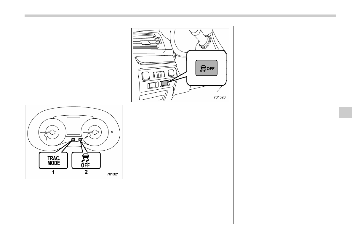
(401,1)
北米Model "A1700BE-B" EDITED: 2017/ 10/ 11
system unable to operate correctly.
& Vehicle Dynamics Control
system monitor
Refer to “Vehicle Dynamics Control warn-
ing light/Vehicle Dynamics Control opera-
tion indicator light” F3-26 and “Vehicle
Dynamics Control OFF indicator light/
Traction mode indicator light /” F3-27.
& Vehicle Dynamics Control
OFF switch
1) Traction mode indicator light
2) Vehicle Dynamics Control OFF indicator
light
Vehicle Dynamics Control OFF switch
When you press the switch briefly or for
more than approximately 2 seconds during
engine operation, the mode of the Vehicle
Dynamics Control system will be changed.
! Vehicle Dynamics Control mode
When the ignition switch is on, this mode is
selected first.
This mode enables all controls for ABS,
the Traction Control System, and the
Vehicle Dynamics Control system. Select
this mode for most driving situations.
When this mode is selected, both indicator
lights on the combination meter turn off.
! Traction mode
This mode restricts the functions of the
Traction Control System and Vehicle Dy-
namics Control system and thus delays
utilizing their functions as a reaction to
vehicle behavior in comparison with the
Vehicle Dynamics Control mode. Use this
mode in driving situations where the
vehicle dynamic performance will improve
without decreasing engine torque control.
When you press the switch briefly during
engine operation, the traction mode in-
dicator light and the Vehicle Dynamics
Control OFF indicator light on the combi-
nation meter illuminate. When you press
the switch again to reactivate the Vehicle
Dynamics Control system, the traction
mode indica tor light a nd the Vehicle
Dynamics Control OFF indicator light turn
off.
! Vehicle Dynamics Control OFF
mode
This mode allows only the ABS control.
When you press the switch for more than
approximately 2 seconds during engine
operation, the Vehicle Dynamics Control
OFF indicator light on the combination
meter illuminates. When you press the
switch again to reactivate the Vehicle
Dynamics Control sys tem, the Vehicle
Dynamics Control OFF indicator light turns
– CONTINUED –
Starting and operating/Vehicle Dynamics Control system
7-39
7
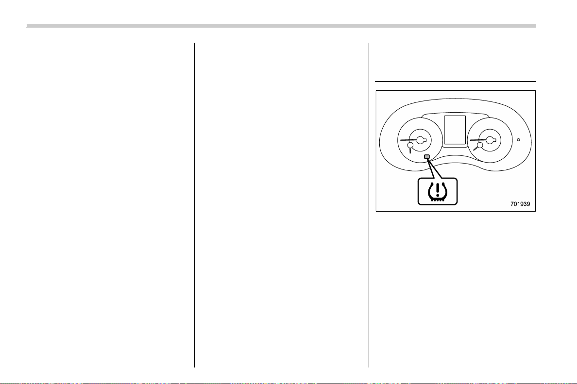
(402,1)
北米Model "A1700BE-B" EDITED: 2017/ 10/ 11
off.
Creating an adequate driving wheel slip by
deactivating the Vehicle Dynamics Control
system temporarily may help to escape
from the following situations. Use the
Vehicle Dynamics Control OFF mode as
necessary.
. a standing start on a steeply sloping
road with a snowy, gravel-covered, or
otherwise slippery surface
. ext rication o f the vehicl e when its
wheels are stuck in mud or deep snow
Yo u shou ld not deactivate the Vehicle
Dynamics Control system except under
the above-mentioned situations.
NOTE
. If you turn the ignition switch to the
“LOCK”/“OFF” position with the Vehi-
cle Dynamics Control system deacti-
vated, the system will be automatically
reactivated the next time the engine is
started.
. If you press and hold the switch for
30 seconds or longer, the Vehicle
Dynamics Control OFF indicator light
turns off, the Vehicle Dynamics Control
system is activated, and the system
ignores a ny further pressing of the
switch. To make the switch usable
again, turn the ignition switch to the
“LOCK”/“OFF” position and restart the
engine.
. When the Vehicle Dynamics Control
OFF mode is selected, the vehicle’s
running performance is comparable
with that of a vehicle that does not have
a Vehicle Dynamics Control system. Do
not deactivate the Vehicle Dynamics
Control system except when absolutely
necessary.
. Even when the Vehicle Dynamics
Control OFF mode is selected, compo-
nents of the brake control system may
still activate. When the brake control
system is activated, the Vehicle Dy-
namics Control operation indicator
light illuminates.
Tire pressure monitoring
system (TPMS) (U.S.-spec.
models)
Low tire pressure warning light
The tire pressure monitoring system pro-
vides the driver with a warning message by
sending a signal from a sensor that is
installed in each wheel when tire pressure
is severely low.
The tire pressure monitoring system will
activate only when the vehicle is driven at
speeds above 20 mph (32 km/h). Also, this
system may not react immediately to a
sudden drop in tire pressure (for example,
a blow-out caused by running over a sharp
object).
Starting and operating/Tire pressure monitoring system (TPMS) (U.S.-spec. models)
7-40
(403,1)
北米Model "A1700BE-B" EDITED: 2017/ 10/ 11
WARNING
. If the low tire pressure warning
light illuminates while driving,
never brake suddenly. Instead,
perform the following procedure.
Otherwise, an accident involving
serious vehicle damage and ser-
ious personal injury could occur.
(1) Keep driving straight ahead
while gradually reducing
speed.
(2) Slowly pull off the road to a
safe place.
(3) Check the pressure for all four
tires and adjust the pressure
to the COLD tire p ressure
shown on the vehicle placard
on the door pillar on the
driver’s side.
Even when the vehicle is driven a
very short distance, the tires get
warm and their pressures in-
crease accordingly. Be sure to
let the tires cool thoroughly be-
fore adjusting their pressures to
the standard values shown on the
tire placard. Refer to “Tires and
wheels” F11-30. The tire pres-
sure monitoring system does not
function when the vehicle is sta-
tionary. After adjusting the tire
pressures, increase the vehicle
speed to at least 20 mph (32 km/h)
to start the TPMS rechecking of
the tire inflation pressures. If the
tire pressures are now above the
severe low pressure threshold,
the low tire pressure warning
light should turn off a few min-
utes later.
If this light still illuminates while
drivi ng after adjusting the tire
pressure, a tire may have signifi-
cant damage and a fast leak that
causes the tire to lose air rapidly.
If you have a flat tire, refer to “Flat
tires” F9-5.
. When a spare tire is mounted or a
wheel rim is replaced without the
original pressure sensor/trans-
mitter being transferred, the low
tire pressure warning light will
illuminate steadily after blinking
for approximately one minute.
This indicates the TPMS is unable
to monitor all four road wheels.
Contact your SUBARU dealer as
soon as possible for tire and
sensor replacement and/or sys-
tem resetting.
. When a tire is repaired with liquid
sealant, the tire pressure warning
valve and transmitter may not
operate properly. If a liquid sea-
lant is used, contact your nearest
SUBARU dealer or other qualified
service shop as soon as possi-
ble. Make sure to replace the tire
pressure warning valve a nd
transmitter when replacing the
tire. You may reuse the wheel if
there is no damage to it and if the
sealant residue is properly
cleaned off. Do not inject any tire
liquid or aerosol tire sealant into
the tires, as this may cause a
malfunction of the tire pressure
sensors. If the light illuminates
steadily after blinking for ap-
proximately one minute,
promptly contact a SUBARU
dealer to have the system in-
spected.
CAUTION
Do not place metal film or any metal
parts in the trunk. This may cause
poor reception of the signals from
the tire pressure sensors, and the
tire pressure monitoring system will
not function properly.
– CONTINUED –
Starting and operating/Tire pressure monitoring system (TPMS) (U.S.-spec. models)
7-41
7
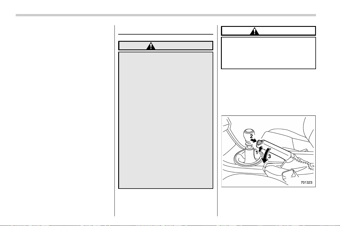
(404,1)
北米Model "A1700BE-B" EDITED: 2017/ 10/ 11
NOTE
This device complies with part 15 of the
FCC Rules. Operation is subject to the
following two conditions: (1) This de-
vice may not cause harmful interfer-
ence, and (2) this device must accept
any i nterference received, including
interference that may cause undesired
operation.
FCC CAUTION
Changes or modifications not ex-
pressly approved by the party respon-
sible for compliance could void the
user’s authority to operate the equip-
ment.
Parking your vehicle
WARNING
. Never leave unattended children
or pets in the vehicle. They could
accidentally injure themselves or
others through inadvertent op-
eration of the vehicle. Also, on
hot or sunny days, the tempera-
ture in a closed vehicle could
quickly become high enough to
cause severe or possibly fatal
injuries to them.
. Do not park the vehicle over
flammable materials such as dry
grass, waste paper or rags, as
they may burn easily if they come
near hot engine or exhaust sys-
tem parts.
. Be sure to stop the engine if you
take a nap in the vehicle. If engine
exhaust gas enters the passen-
ger compartment, occupants in
the vehicle could die from carbon
monoxide (CO) contained in the
exhaust gas.
CAUTION
TYPE RA: When parking the vehicle,
be careful not to contact a wheel
stop, etc. Doing so may damage the
bumpers, underside of the vehicle,
etc.
& Parking brake (models with-
out electronic parking brake
system)
To set the parking brake, depress the
brake pedal firmly and hold it down until
the parking brake lever is fully pulled up.
To release the parking brake, perform the
following procedure.
1. Pull the lever up slightly.
Starting and operating/Parking your vehicle
7-42
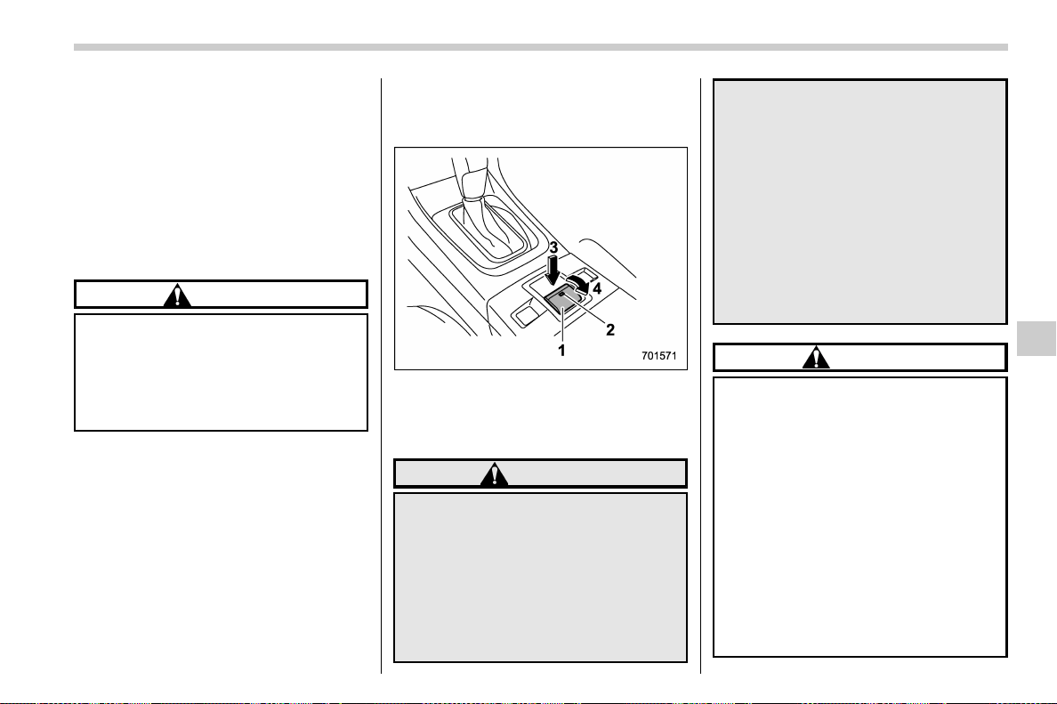
(405,1)
北米Model "A1700BE-B" EDITED: 2017/ 10/ 11
2. Press the release button.
3. Lower the lever while keeping the
button pressed.
When the parking brake is set while the
engine is running, the parking brake
warning light illuminates. Be sure that the
warning light is turned off before driving off.
Refer to “Parking brake indicator (models
without electronic parking brake system)”
F3-21.
CAUTION
Never drive while the parking brake
is set because this will cause un-
necessary wear on the brake linings.
Make sure that the parking brake has
been fully released before driving
off.
& Electronic parking brake
(models with electronic park-
ing brake system)
1) Parking brake switch
2) Indicator light
3) Release the electronic parking brake
4) Apply the electronic parking brake
WARNING
. Before exiting the vehicle, make
sure that you turn off the engine.
Otherwise, the parking brake may
be released and an accident may
occur.
. If the brake system warning light
turns on, the electronic parking
brake system may be malfunc-
tioning. Immediately stop your
vehicle in a safe location, use tire
stops under the tires to prevent
the vehicle from moving and
contact your SUBARU dealer.
. If you operate the electronic park-
ing brake when the brake is over-
heated or the vehicle is on a steep
slope, the electronic parking
brake indicator light may flash.
In this case, the vehicle may start
to move and it may lead to an
accident. Always use the tire
stops.
CAUTION
. When th e electronic parking
brake system has a malfunction
and the parking brake cannot be
applied, contact your SUBARU
dealer immediately for an inspec-
tion. If you have to park your
vehicle in such conditions, per-
form the following procedure.
– Stop your vehicle in a flat
location.
– Shift the select lever in the “P”
position. When the select le-
ver cannot be shifted into the
“P” position, you must release
shift lock. Refer to “Shift lock
– CONTINUED –
Starting and operating/Parking your vehicle
7-43
7

(406,1)
北米Model "A1700BE-B" EDITED: 2017/ 10/ 11
function” F7-27.
– Use tire stops under the tires
to prevent the vehicle from
moving.
. Never drive with the parki ng
brake applied. Doing so will
cause unnecessary wear on the
brake linings. Before driving off,
always make sure that the park-
ing brake has been released and
the brake system warning light
has turned off.
Your vehicle is equipped with an electronic
parking brake. You can apply/release the
parking brake by operating the parking
brake switch.
To apply: Depress the brake pedal and
pull up the parking brake switch.
To release: Press the parking brake
switch firmly while the ignition switch is in
the “ON” position and the brake pedal is
depressed.
When the parking brake is applied while
the ignition switch is in the “ON” position,
the electronic parking brake indicator light
and the indicator light on the parking brake
switch illuminate. Refer to “Brake system
warning light” F3-21.
NOTE
. If you press the parking brake switch
under the following conditions, the
parking brake will not be released.
– The ignition switch is in the
“ACC” or “LOCK”/“OFF” position.
– You are not depressing the brake
pedal.
. The electronic parking brake system
uses motors to apply the parking brake.
Therefore, operating sounds from the
motors will be heard when applying or
releasing the parking brake. Make sure
that the motor sounds are heard when
applying or releasing the parking
brake.
. If you operate the parking brake
switch under the following conditions,
a chirp will sound and the electronic
parking brake indicator light will flash.
– when the electronic parking
brake system has a malfunction
– when the electronic parking
brake operation is prohibited tem-
porarily
. When you cannot release the park-
ing brake due to, for example, a system
malfunction, contact your SUBARU
dealer and have your SUBARU dealer
release the parking brake.
. If you stop operating the electronic
parking brake switch midway or oper-
ate extremely slowly, the system may
detect an error and turn on the brake
system warning light. However, this
does not indicate a malfunction if the
brake system warning light turns off
after operating the switch.
. When the electronic parking brake
has not been used for a long period of
time, the electronic parking brake may
operate automatically after the ignition
switch is turned to the “LOCK”/“OFF”
position. This occurs due to checking
the proper operation of the electronic
parking brake and does not indicate a
malfunction.
. If you cannot release the electronic
parking brake due to the switch mal-
function, refer to the instructions de-
scribed in “Automatic release function
by accelerator pedal” F7-45.
After activating the electronic parking
brake, you may hear a short sound
several minutes after the electronic
parking brake indicator light illumi-
nates as the system confirms proper
engagement. This sound is different
from the apply and release sound.
This can occur:
– If the brakes are extremely hot.
– If the car is parked on a steep
incline.
Starting and operating/Parking your vehicle
7-44
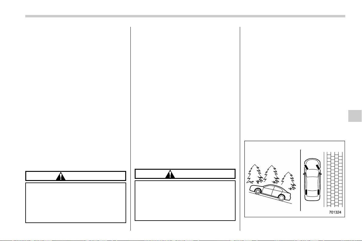
(407,1)
北米Model "A1700BE-B" EDITED: 2017/ 10/ 11
– If the electronic parking brake is
applied after the ignition switch is
turned OFF.
This is a normal operating sound under
any of these conditions.
! Automatic release function by ac-
celerator pedal
The parking brake will be automatically
released by depressing the accelerator
pedal. However, the automatic release
function does not operate under the
following conditions.
. Any door (other than the trunk lid) is
open.
. The driver’s seatbelt is not fastened.
If the parking brake is automatically
released, the electronic parking brake
indicator light and the indicator light on
the parking brake switch turn off.
! Emergency brake
CAUTION
Use the emergency brake only in
case of an emergency. If the emer-
gency brake is excessively used, the
brake parts will wear down faster or
the brake may not work sufficiently
due to brake overheating.
NOTE
While using the emergency brake:
. The electronic parking brake indica-
tor light and the indicator light on the
parking brake switch illuminate and a
chirp sounds.
. A sound may be heard from the
engine compartment. This is the oper-
ating sound of the brake that is acti-
vated by the Vehicle Dynamics Control
system, and does not indicate a mal-
function.
If the foot brake has a malfunction, you can
stop the vehicle by pulling the parking
brake switch continuously.
While applying the emergency brake, the
electronic parking brake indicator light and
the indicator light on the parking brake
switch illuminate and a chirp sounds.
! Electronic parking brake system
warning
CAUTION
If the brake system warning light
turns on, the electronic parking
brake system may be malfunction-
ing. Immediately stop your vehicle in
the nearest safe location and con-
tact your SUBARU dealer.
If a malfunction occurs in the electronic
parking brake system, the brake system
warning light turns on. Refer to “Electronic
parking brake indicator light (models with
electronic parking brake system) ” F3-23.
& Parking tips
When parking your vehicle, always per-
form the following items.
. Apply the parking brake firmly.
. For MT models, put the shift lever in the
“1” (1st) for upgrade or “R” (Reverse) for a
downgrade.
. For CVT models, put the select lever in
the “P” (Park) position.
Never rely on the mechanical friction of the
transmission alone to hold the vehicle.
When parking on a hill, always turn the
– CONTINUED –
Starting and operating/Parking your vehicle
7-45
7
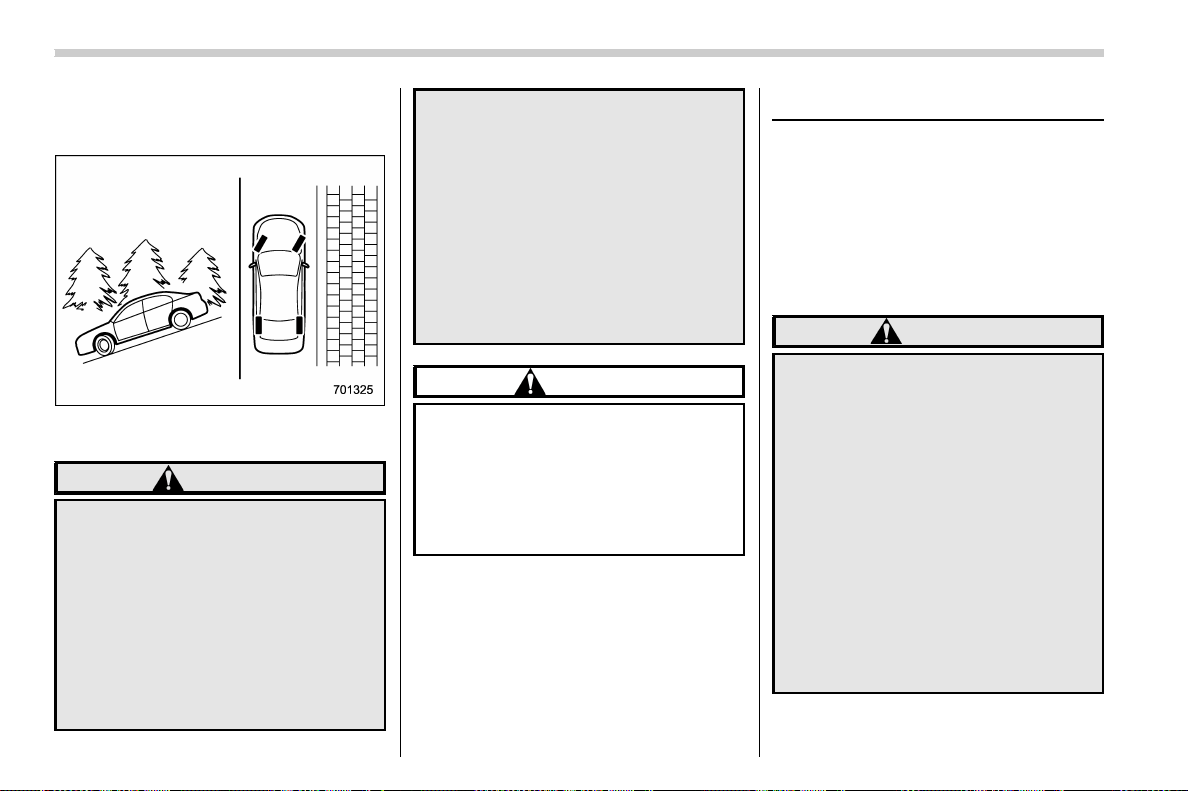
(408,1)
北米Model "A1700BE-B" EDITED: 2017/ 10/ 11
steering wheel. When the v ehicle is
headed up the hill, turn the front wheels
away from the curb.
When facing downhill, turn the front
wheels into the curb.
WARNING
. Never leave unattended children
or pets in the vehicle. They could
accidentally injure themselves or
others through inadvertent op-
eration of the vehicle. Also, on
hot or sunny days, the tempera-
ture in a closed vehicle could
quickly become high enough to
cause severe or possibly fatal
injuries to people.
. Do not park the vehicle over
flammable materials such as dry
grass, waste paper or rags, as
they may burn easily if they come
near hot engine or exhaust sys-
tem parts.
. Be sure to stop the engine if you
take a nap in the vehicle. If engine
exhaust gas enters the passen-
ger compartment, occupants in
the vehicle could die from carbon
monoxide (CO) contained in the
exhaust gas.
CAUTION
If your vehicle has a front under-
spoiler and rear underspoiler (both
optional), pay atten tion to blocks
and other obs tructions on the
ground when parking. The under-
spoilers could be damaged by con-
tact with them.
Auto Vehicle Hold function
The Auto Vehicle Hold function will auto-
matically keep the vehicle stopped even
after releasing the brake pedal when the
vehicle is at a complete stop, such as at
traffic signals. The function will be can-
celed by either of the following operations.
. Depressing the accelerator pedal
. Depressing the brake pedal again
WARNING
. Do not use the Auto Vehicle Hold
function on a steep hill or slip-
pery road. The vehicle may move
even when using the Auto Vehicle
Hold function, causing serious
injury or accidents.
. Do not use the Auto Vehicle Hold
function to park the vehicle. The
vehicle may move unexpectedly,
causing serious injury or acci-
dents. Make sure to shift the
select lever to the “P” position
and apply the electronic parking
brake in the following cases.
– When you are going to park
your vehicle
Starting and operating/Auto Vehicle Hold function
7-46

(409,1)
北米Model "A1700BE-B" EDITED: 2017/ 10/ 11
– When passengers are getting
in or out of the vehicle
– When you are loading or un-
loading
. When using the Auto Vehicle
Hold function, do not release the
brake pedal before the Auto Ve-
hicle Hold o peration indicator
illuminates. The vehicle may
move unexpectedly, causing ser-
ious injury or accidents.
. Deactivate the Auto Vehicle Hold
function in the following cases.
Otherwise, the vehicle may move
unexpectedl y, causing seriou s
injury or accidents.
– When washing your vehicle in
an automatic car wash
– When being towed
– When towing a vehicle
CAUTION
When stopping on a steep slope with
the Auto Vehicle Ho ld function
turned on, the electronic parking
brake may be automatically applied.
Then the electronic parking brake
indicator light will flash. In such a
case, depress and hold the brake
pedal while stopping. Otherwise, the
vehicle may move.
NOTE
We recommend turning on the Auto
Vehicle Hold function when stopping
on an incline. If the Auto Vehicle Hold
function is turned off, the vehicle may
roll backward when driving off.
& To turn on/off the Auto Vehi-
cle Hold function
Auto Vehicle Hold switch
Auto Vehicle Hold ON indicator light
To turn on:
Press the Auto Vehicle Hold switch when
the Auto Vehicle Hold ON indicator light is
OFF. Then the Auto Vehicle Hold ON
indicator light will illuminate.
Even after turning on the Auto Vehicle
Hold function, it will automatically turn off
once the ignition switch is turned to the
“LOCK”/“OFF” position. The function will
remain turned off when the ignition switch
is turned back to the “ON” position.
To turn off:
Press the Auto Vehicle Hold switch when
the Auto Vehicle Hold ON indicator light
illuminates. Then the Auto Vehicle Hold
ON indicator light will turn off.
– CONTINUED –
Starting and operating/Auto Vehicle Hold function
7-47
7
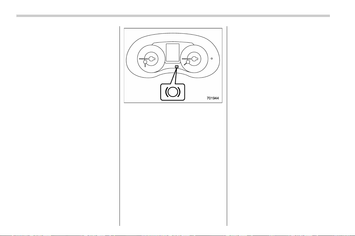
(410,1)
北米Model "A1700BE-B" EDITED: 2017/ 10/ 11
NOTE
. IfyoupressandholdtheAuto
Vehicle Hold switch for more than 30
seconds, the Auto Vehicle Ho ld ON
indicator light will turn off, and the
system will ignore any further pressing
of the switch. To activate the switch
again, restart the engine.
. When the Auto Vehicle Hold function
is deactivated while the Auto Vehicle
Hold function has a malfunction, if you
press the Auto Vehicle Hold switch, a
chirp will sound
& To operate the Auto Vehicle
Hold function
Stop the vehicle by depressing the brake
pedal when all of the following conditions
are m et. Then the Auto Vehicle Hold
function will operate.
. All doors are closed.
. The driver’s seatbelt is fastened.
. The select lever is in a position other
than the “P” position.
Auto Vehicle Hold operation indicator light
While the vehicle is kept stopped by the
Auto Vehicle Hold fun ction, the Auto
Vehicle Hold operation indicator light will
illuminate.
& To release the Auto Vehicle
Hold function
Perform any of the following operations to
release the Auto Vehicle Hold function.
. Depress the accelerator pedal.
. Depress the brake pedal again.
. Apply the electronic parking brake.
. Shift the select lever to the “P” position
with the brake pedal pressed.
. Press the Auto Vehicle Hold switch with
the brake pedal pressed.
When the Auto Vehicle Hold function is
released, the Auto Vehicle Hold operation
indicator light will turn off.
Under any of the following conditions, the
Auto Vehicle Hold function will be auto-
matically released and the electronic
parking brake will be automatically ap-
plied.
. The Auto Vehicle Hold function has
been in operation for 10 minutes.
. The driver’s seatbelt is unfastened.
. The driver’s door is opened.
. The ignition switch is turned to the
“LOCK”/“OFF” position.
. The vehicle is stopped on a steep
slope.
. The Auto Vehicle Hold function is
malfunctioning.
In such cases, the Auto Vehicle Hold
operation indicator light will turn off and
the indicator light on the parking brake
switch will illuminate.
& Tips
. When the electronic parking brake is
automatically applied with the vehicle kept
stopped by the Auto Vehicle Hold function,
release the electronic parking brake by
either of the following operations before
starting off. Then make sure that the
Starting and operating/Auto Vehicle Hold function
7-48
(411,1)
北米Model "A1700BE-B" EDITED: 2017/ 10/ 11
electronic parking brake indicator light is
off.
– Depress the accelerator pedal with
the driver’s seatbelt fastened and with
the doors closed.
– Press the electronic parking brake
switch with the brake pedal depressed.
. Under certain conditions, including a
malfunction of the Auto Vehicle Hold, a
warning buzzer will sound and a warning
message will appear on the combination
meter display (color LCD). All warning
messages should be strictly observed.
. On a steep slope, the vehicle cannot be
kept stopped by the Auto Vehicle Hold
function. In such a case, depress and hold
the brake pedal.
. When stopping on a steep slope with
the Auto Vehicle Hold function activated,
the electronic parking brake may automa-
tically be applied after stopping, then the
electronic parking brake indicator light
may flash. In such a case, depress and
hold the brake pedal while stopped.
Otherwise, the vehicle may move. When
getting out of the vehicle, stop the vehicle
on a flat surface, then apply the electronic
parking brake.
. If the Auto Vehicle Hold ON indicator
light does not illuminates even after
pressing the Auto Vehicle Hold switch with
the operating conditions met, the function
may have a malfunction. Contact your
SUBARU dealer for an inspection.
. You may hear a sound while the Auto
Vehicle Hold function is keeping your
vehicle stopped. This is normal, and does
not represent a malfunction.
. While the vehicle is kept stopped by the
Auto Vehicle Hold function, the brake
pedal may feel stiff. However, this is not a
malfunction.
. When using the Auto Vehicle Hold
function, depress the brake pedal firmly.
Otherwise, the Auto Vehicle Hold may not
operate.
. When the Auto Vehicle Hold switch is
pressed and hel d for more th an 30
seconds, the Auto Vehicle Hold ON in-
dicator light will turn off and further opera-
tion of the switch will be ignored. To make
the switch usable again, turn the ignition
switch to the “LOCK”/“OFF” position and
then turn it to the “ON” position.
Hill start assist system
WARNING
. The Hill start assist system is a
device only for helping the driver
to START the vehicle on an uphill
grade. To prevent accidents
when the vehicle is parked on a
slope, be sure to firmly set the
parking brake. When setting the
parking brake, make sure that the
vehicle remains stationary when
the clutch pedal (MT models) and
brake pedal (both MT and CVT
models) are released.
. Do not turn the ignition switch to
the “LOCK”/“OFF” position while
the H ill start assist system is
operating. The Hill start assist
system will be deactivated, caus-
ing an accident.
NOTE
For models with the electronic parking
brake system:
. The Hill start assist system will
activate when the Auto Vehicle Hold
function is deactivated.
. The Hill start assist system will
– CONTINUED –
Starting and operating/Hill start assist system
7-49
7
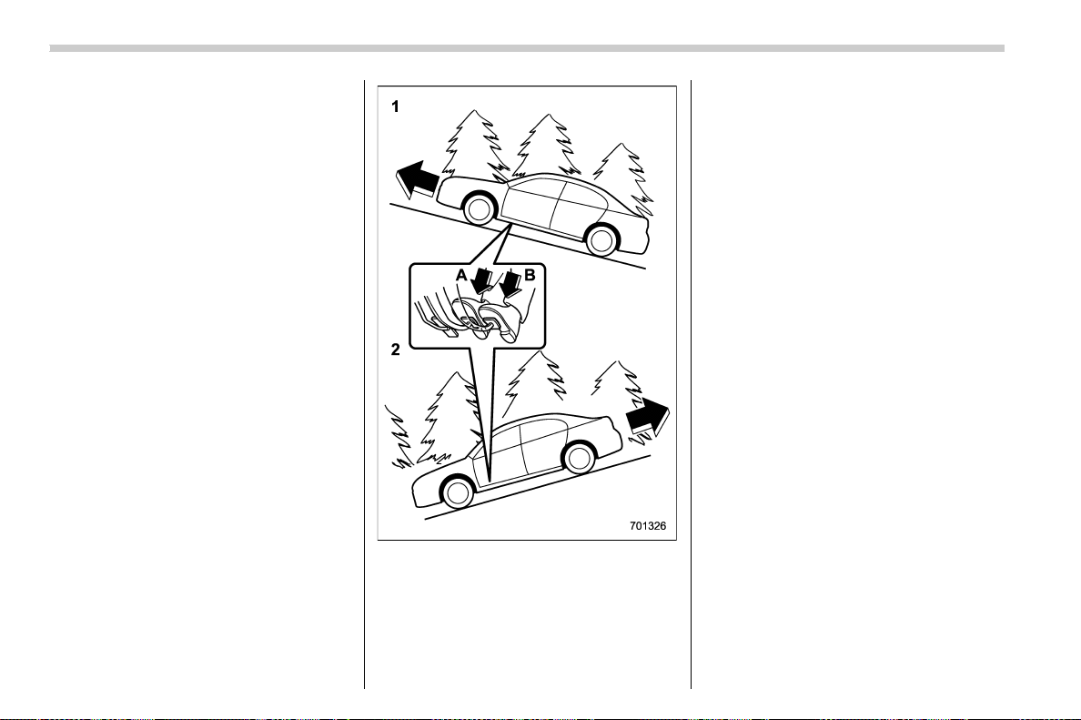
(412,1)
北米Model "A1700BE-B" EDITED: 2017/ 10/ 11
deactivate when the Auto Vehicle Hold
function is activated.
The Hill start assist system is a device to
make the following vehicle operations
easier.
1) Starting forward facing uphill
2) Starting backward facing downhill
A) Brake pedal (both MT models and CVT
models)
B) Clutch pedal (MT models only)
In both these cases, the Hill start assist
system operates under the following con-
ditions.
. when depressing both the clutch pedal
and the brake pedal (MT models)
. when the vehicle has stopped with the
brake pedal depressed (CVT models)
Braking power is maintained temporarily
(for approximately 2 seconds) by the Hill
start assist system after the brake pedal is
released. The driver is therefore able to
start the vehicle in the same way as on a
level grade, just using the clutch pedal (MT
models only) and accelerator pedal (all
models).
If the braking power of the Hill start assist
system is insufficient after the brake pedal
is released, apply more braking power by
depressing the brake pedal again.
The Hill start assist system may not
operate on slight grades. Also, the Hill
start assist system does not operate in the
following cases.
Starting and operating/Hill start assist system
7-50
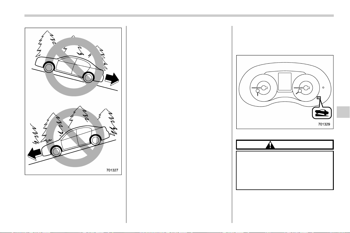
(413,1)
北米Model "A1700BE-B" EDITED: 2017/ 10/ 11
. when starting backward facing uphill
. when starting forward facing downhill
. while the parking brake is applied
. while the ignition switch is in the “ACC”
or “LOCK”/“OFF” position
. while the Hill start assist warning light/
Hill start assist OFF in dicator light is
illuminated (models without the electronic
parking brake system)
When using the Hill start assist system, a
braking effect may be felt even after the
brake pedal has been released. However,
this braking effect should disappear once
the clutch pedal is released.
NOTE
A slight jolt may be felt when the
vehicle begins to move forward after
being reversed.
& To activate/deactivate the Hill
start assist system (models
without the electronic park-
ing brake system)
Hill start assist OFF indicator light
CAUTION
When starting on an uphill grade,
make sure the Hill start assist OFF
indicator light is off. If the Hill start
assist OFF indicator light is on,
make sure the parking brake is
applied.
To activate and deactivate the Hill start
assist system, perform the following steps.
– CONTINUED –
Starting and operating/Hill start assist system
7-51
7
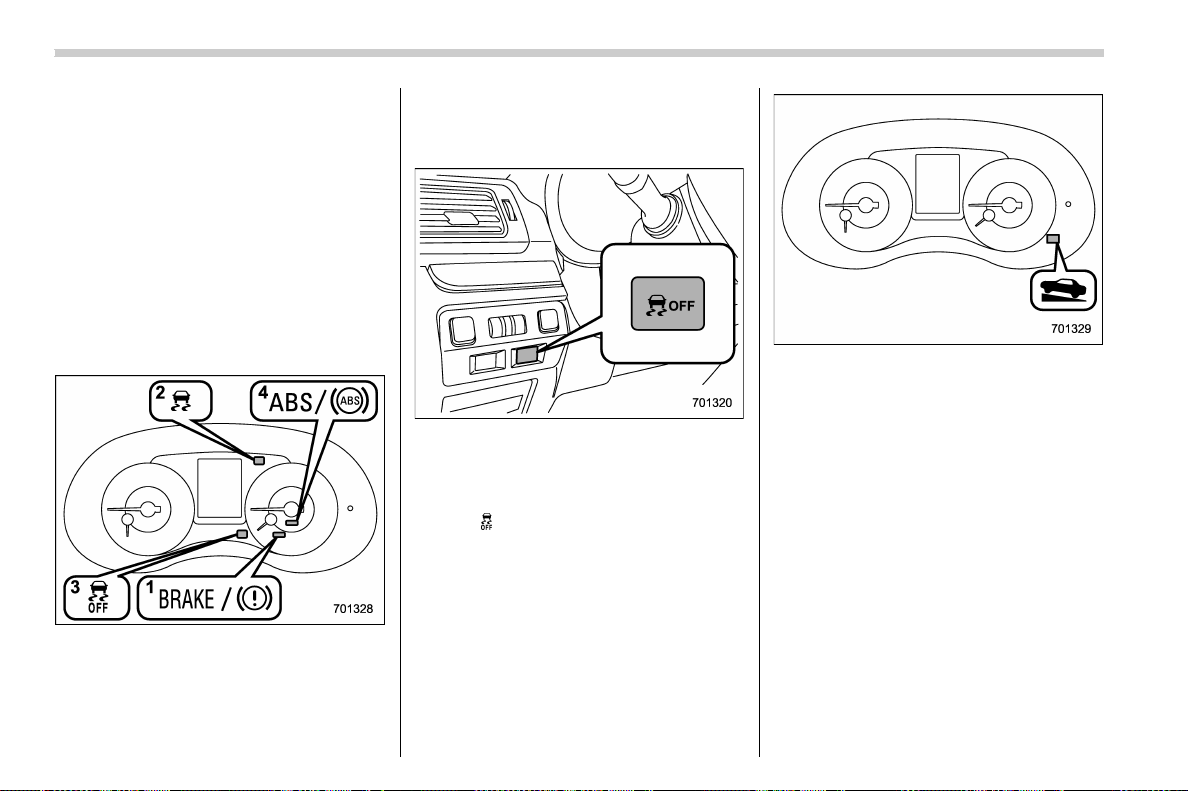
(414,1)
北米Model "A1700BE-B" EDITED: 2017/ 10/ 11
NOTE
If you make an error when performing
any steps in the following procedure,
place the ignition switch in the “LOCK”/
“OFF” position once and then start
over again.
! To deactivate
1. Park your vehicle in a flat and safe
location and apply the parking brake.
2. Turn the ignition switch to the “LOCK”/
“OFF” position.
3. Restart the engine.
4. Confirm the following items.
(1) The Brake system warning light
illuminates.
(2) The Vehicle Dynamics Control
warning light turns off.
(3) The Vehicle Dynamics Control
OFF indicator light turns off.
(4) The ABS warning light turns off.
Vehicle Dynamics Control OFF switch
5. Press and hold the Vehicle Dynamics
Control OFF switch for 30 seconds until
the Vehicle Dynamics Control OFF indica-
tor light “
” on the combination meter turns
on and off.
6. Within 5 seconds, release the Vehicle
Dynamics Control OFF switch.
Hill start assist OFF indicator light
7. Within 2 seconds, press back the
Vehicle Dynamics Control OFF switch.
The Hill start assist OFF indicator light
turns on and off.
8. Turn the ignition switch to the “LOCK”/
“OFF” position. The Hill start assist system
is deactivated.
NOTE
When the Hill start assist system is
deactivated, the Hill start assist OFF
indicator light illuminates continu-
ously.
Starting and operating/Hill start assist system
7-52
(415,1)
北米Model "A1700BE-B" EDITED: 2017/ 10/ 13
! To reactivate
To reactivate the Hill start assist system,
repeat steps 1 to 8. When the Hill start
assist system is activated, the Hill start
assist OFF indicator light turns off.
& Hill start assist warning light/
Hill start assist OFF indicator
light (models without the
electronic parking brake sys-
tem)
Refer to “Hill start assist warning light/Hill
start assist OFF indicator light (models
without electronic parking brake system)”
F3-24.
Cruise control
NOTE
For models with the EyeSight system:
Refer to the Owner’s Manual supple-
ment for the EyeSight system.
Cruise control enables you to maintain a
constant vehicle speed without holding
your foot on the accelerator pedal and it is
operative when the vehicle speed is 20
mph (30 km/h) or more.
WARNING
. Do not use the cruise control
under any of the following condi-
tions. These may cause loss of
vehicle control.
– driving up or down a steep
grade
– driving on slippery or winding
roads
– driving in heavy traffic
. When using the cruise control,
always set the speed appropri-
ately according to the speed limit,
traffic flow, road conditions, and
other conditions.
NOTE
. On uphill and downhill slopes, de-
pending on the degree of the slope and
the load of the vehicle, there may be
cases when a constant speed cannot
be guaranteed.
. If the cruise control indicator does
not appear even after pressing the
cruise control main button, it is possi-
ble that there is a malfunction in the
system. We recommend that you con-
tact your SUBARU dealer for an inspec-
tion.
. Make sure the cruise control system
is turned off when the cruise control is
not in use to avoid unintentionally
setting the cruise control.
– CONTINUED –
Starting and operating/Cruise control
7-53
7
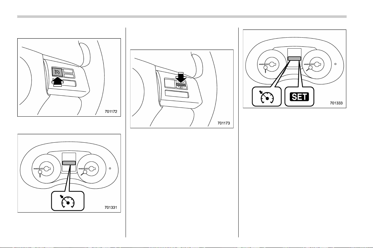
(416,1)
北米Model "A1700BE-B" EDITED: 2017/ 10/ 11
& To set cruise control
Cruise control main button
1. Press the cruise control main button.
Cruise control indicator
The cruise control indicator on the combi-
nation meter will appear.
2. Depress the accelerator pedal until the
vehicle reaches the desired speed.
3. Press the “RES/SET” switch to the
“SET” side and release it. Then release the
accelerator pedal.
NOTE
Except STI: When setting a cruise
speed for the first time during a drive,
both “SET” and “RES” may be used to
set the initial cruise speed.
Cruise control set indicator
At this time, the cruise control set indicator
appears in the combination meter.
The vehicle will maintain the desired
speed.
You can temporarily increase the vehicle
speed while driving with the cruise control
activated. Simply depress the accelerator
pedal to accelerate the vehicle. When you
release the accelerator pedal, the vehicle
will return to and maintain the previous
cruising speed.
NOTE
For CVT models, when you set the
desired speed while the Sport Sharp
(S#) mode is selected, the select lever/
gear position indicator will change
from the current gear position indica-
Starting and operating/Cruise control
7-54
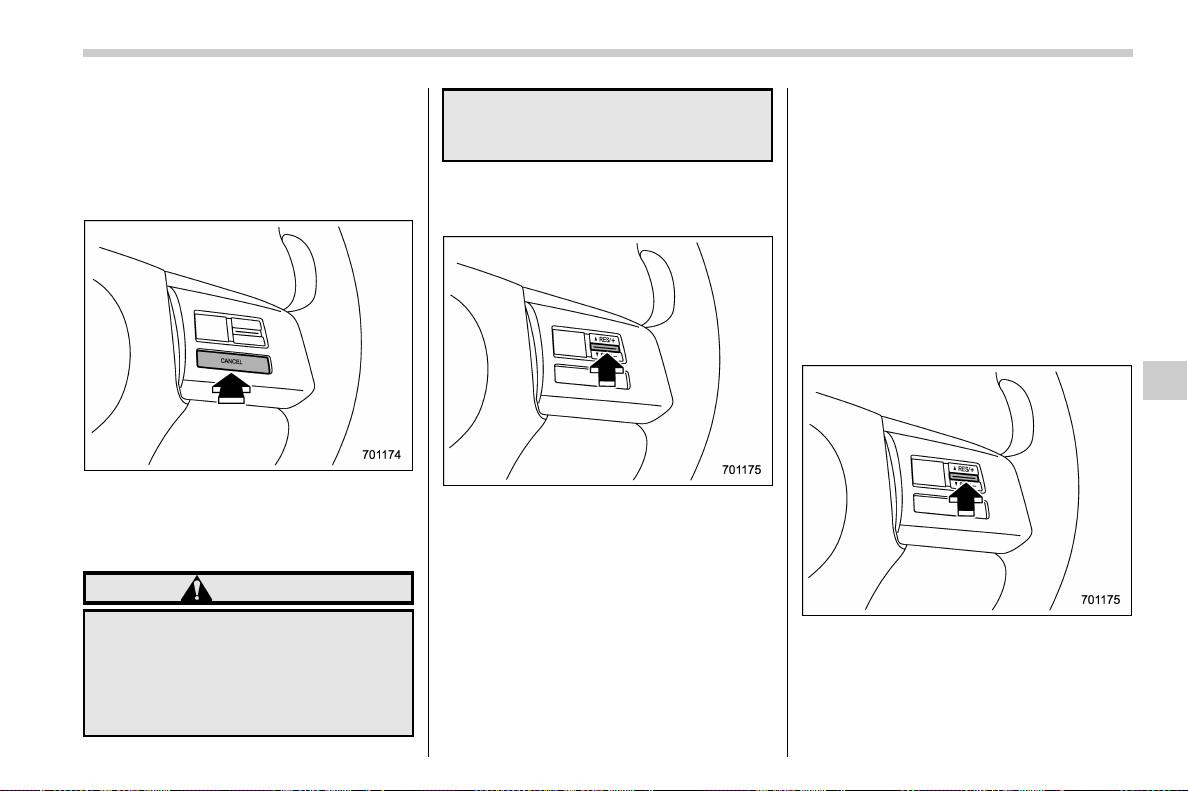
(417,1)
北米Model "A1700BE-B" EDITED: 2017/ 10/ 11
tion to the “D” indication.
& To temporarily cancel the
cruise control
Yo u can temporarily cancel the cruise
control in the following ways.
. Press the “CANCEL” button.
. Depress the brake pedal.
. Depress the clutch pedal (MT models
only).
WARNING
For CVT models, you can cancel the
cruise control by shifting the select
lever into the “N” position. However,
do not shift the lever into the “N”
position while driving except in case
of emergency. If the select lever is
shifted into the “N” position, the
engine brake will no longer work.
This could result in an accident.
The cruise control set indicator in the
combination meter disappears when the
cruise control is canceled.
To resume the cruise control after it has
been temporarily canceled and with vehi-
cle speed of approximately 20 mph (30
km/h) or more, press the “RES/SET”
switch to the “RES” side to return to the
original cruising speed automatically.
The cruise control set indicator in the
combination meter will automatically ap-
pear at this time.
& To turn off the cruise control
There are two ways to turn off the cruise
control:
. Press the cruise control main button
again.
. Turn the ignition switch to the “ACC” or
“LOCK”/“OFF” position (but only when the
vehicle is completely stopped).
& To change the cruising speed
! To increase the speed (by the “RES/
SET” switch)
Press the “RES/SET” switch to the “RES”
side and hold it until the vehicle reaches
the desired speed. The n, release the
switch. The vehicle speed at that moment
will be memorized and treated as the new
set speed.
– CONTINUED –
Starting and operating/Cruise control
7-55
7
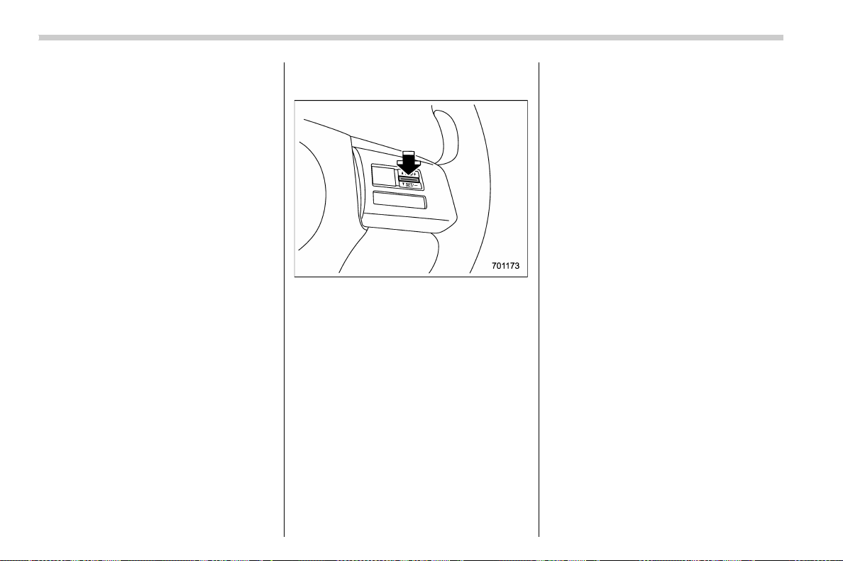
(418,1)
北米Model "A1700BE-B" EDITED: 2017/ 10/ 11
You can increase the set speed 1 mph (1.6
km/h) or 1 km/h (0.6 mph) each time by
pressing th e “RE S/SET” switch to t he
“RES” side quickly.
! To increase the speed (by accelera-
tor pedal)
1. Depress the accelerator pedal to ac-
celerate the vehicle to the desired speed.
2. Press the “RES/SET” switch to the
“SET” side once. Now the desired speed is
set and the vehicle will keep running at that
speed without depressing the accelerator
pedal.
NOTE
CVT models:
. If you depress the accelerator pedal
with the Sport Sharp (S#) mode se-
lected, the select lever/gear position
indi cator may change from the “D”
indication to the current gear position
indication.
. If you depress the accelerator pedal
fully with the Intelligent (I) mode or the
Sport (S) mode selected, the transmis-
sion will operate like a conventional
automatic transmission.
! To decrease the speed (by the “RES/
SET” switch)
Press the “RES/SET” switch to the “SET”
side and hold it until the vehicle reaches
the desired spee d. Then, release the
switch. The vehicle speed at that moment
will be memorized and treated as the new
set speed.
You can lower the set speed 1 mph (1.6
km/h) or 1 km/h (0.6 mph) each time by
pressing the “RES/SET” switch to the
“SET” side quickly.
! To decrease the speed (by brake
pedal)
1. Depress the brake pedal to release
cruise control temporarily.
2. When the speed decreases to the
desired speed, p ress the “RES/SET”
switch to the “SET” side once. Now the
desired speed is set and the vehicle will
keep running at that speed without depres-
sing the accelerator pedal.
& Cruise control indicator
Refer to “Cruise control indicator” F3-35.
& Cruise control set indicator
Refer to “Cruise control set indicator” F3-
35.
Starting and operating/Cruise control
7-56

(419,1)
北米Model "A1700BE-B" EDITED: 2017/ 10/ 11
BSD/RCTA (if equipped)
The BSD/RCTA consists of rear radar with
Blind Spot Detection and Rear Cross
Traffic Alert.
These functions enable the system to
detect objects or vehicles to the rear,
drawing attention to the driver wh en
changing a lane or when driving in reverse.
WARNING
The driver is responsible for driving
safely. Always be sure to check the
surroundings with your eyes when
changing lanes or reversing the
vehicle.
The system is designed to assist the
driver in changing lanes or rever-
sing safely by monitoring the rear
and side areas of the vehicle. How-
ever, you cannot rely on this system
alone in assuring the safety during a
lane change or reversing. Overcon-
fidence in this system could result in
an accident and lead to serious
injury or death. Since the system
operation has various limitation s,
the flashing or illumination of the
BSD/RCTA approach indicator light
may be delayed or it may not operate
at all even when a vehicle is present
in a neighboring lane or approach-
ing from either side.
The driver is responsible for paying
attention to the rear and side areas
of the vehicle.
& System features
BSD/RCTA consists of the following func-
tions.
. To detect a vehicle in a blind spot on an
adjacent lane or a vehicle approaching at
high speed while driving the vehicle (Blind
Spot Detection)
. To detect a vehicle approaching from
the right or left while reversing the vehicle
(Rear Cross Traffic Alert)
The system uses radar sensors for the
following features.
NOTE
The BSD/RCTA radar sensor has been
certified by the radio wave related laws
of the U.S. and Canada. When driving in
other countries, certification of the
country where the vehicle is driven
must be obtained. For certification in
the U.S. and Canada, refer to “Certifica-
tion for the BSD/RCTA” F7-64.
! Blind Spot Detection (BSD)
1) Operating range
The system warns the driver of dangers as
follows.
. If the system detects vehicles in the
driver’s blind spots, the BSD/RCTA ap-
proach indicator light(s) on the outside
mirror(s) will illuminate.
. If the driver operates the turn signal
lever to the side where the BSD/RCTA
approach indicator light is illuminated, the
corresponding BSD/RCTA approach indi-
cator light will flash.
– CONTINUED –
Starting and operating/BSD/RCTA
7-57
7
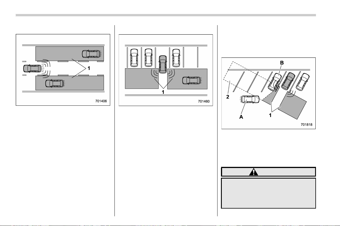
(420,1)
北米Model "A1700BE-B" EDITED: 2017/ 10/ 11
! Lane Change Assist (LCA)
1) Operating range
The system warns the driver of dangers as
follows.
. If the system detects vehicles ap-
proaching at high speeds in the neighbor-
ing lanes, the BSD/RCTA approach indi-
cator light(s) on the outside mirror(s) will
illuminate.
. If the driver operates the turn signal
lever to the side where the BSD/RCTA
approach indicator light is illuminated, the
corresponding BSD/RCTA approach indi-
cator light will flash.
! Rear Cross Traffic Alert (RCTA)
1) Operating range
The system notifies the driver of another
vehicle approaching from either side when
driving in reverse. This feature helps the
driver check the rear and side areas of the
vehicle when moving backward.
If the system detects a vehicle approach-
ing from either side while moving back-
ward, it warns the driver of dangers in the
following way.
. The BSD/RCTA approach indicator
light(s) on the outside mirror(s) flashes.
. A warning buzzer sounds.
! Limitations of the detectability of
RCTA
Since the detectability of RCTA is limited,
the RCTA may not operate properly in
angled parking.
Example 1
1) The detection range of the radar sensors
2) Area out of detection range of the radar
sensors
A) Vehicle that may not be detected
B) Parked vehicle
WARNING
An approaching vehicle (A) may not
be detected because the detection
range is limited by the parked vehi-
cle (B). Always be sure to check the
surroundings with your eyes when
Starting and operating/BSD/RCTA
7-58
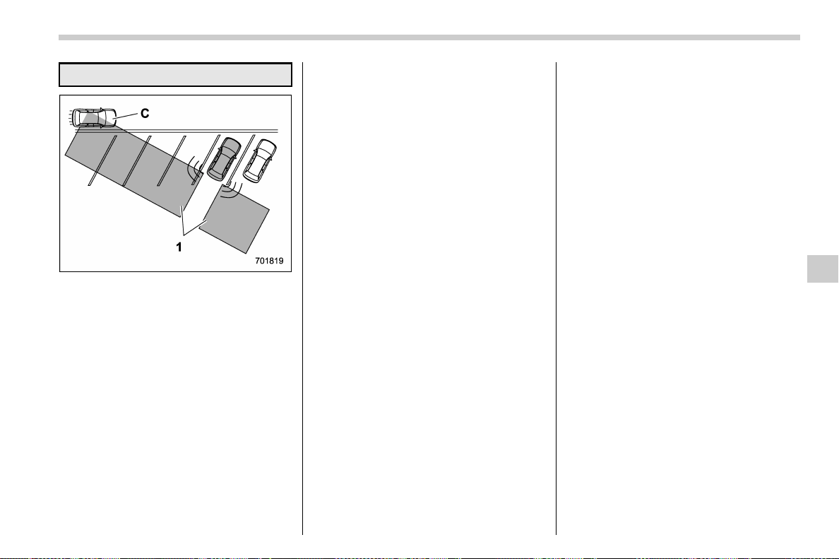
(421,1)
北米Model "A1700BE-B" EDITED: 2017/ 10/ 11
reversing the vehicle.
Example 2
1) The detection range of the radar sensors
C) Vehicle that may be detected
NOTE
The system may detect that a vehicle
(C) is passing in front of your vehicle.
Always be sure to check the surround-
ings with your eyes when reversing the
vehicle.
& System operation
! Operating conditions
The BSD/RCTA will operate when all of the
following conditions are met.
. The ignition switc h is in the “ON ”
position.
. The BSD/RCTA warning indicator and
BSD/RCTA OFF indicator are turned off.
. The vehicle speed is above 7 mph (12
km/h) (except when reversing).
. The shift lever/select lever is in the “R”
position (RCTA only).
The BSD/RCTA will not operate in the
following situations.
. The BSD/RCTA OFF indicator is on.
. The vehicle speed is below 6 mph (10
km/h) even when the BSD/RCTA OFF
indicator remains off (except when rever-
sing).
NOTE
. When a malfunction occurs in the
system (including the BSD/RCTA ap-
proach indicator light), the BSD/RCTA
will stop operating and the BSD/RCTA
warning indicator will appear.
. If the BSD/RCTA warning indicator
appears, exercise proper caution. For
details, refer to “BSD/RCTA warning
indicator” F7-62.
. In the following cases, the BSD/
RCTA will temporarily stop operating
(or may stop operating) and the BSD/
RCTA warning indicator will appear.
– When the radar sensor becomes
significantly misaligned (If the or-
ientation of the radar sensor is
shifted for any reason, readjust-
ment is required. Have the sensor
adjusted at a SUBARU dealer.)
– When a large amount of snow or
ice sticks to the rear bumper sur-
face around the radar sensors
– When the vehicle is driven on a
snow-covered road or in an envir-
onment in which there are no ob-
jects around (such as in a desert) for
a prolonged period of time
– When the temperature around the
radar sensors increases exces-
sively due to long driving on uphill
grades in the summer, etc.
– When the temperature around the
radar sensors becomes extremely
low
– When the vehicle battery voltage
lowers
– When the vehicle voltage ex-
ceeds the battery voltage rating
The BSD/RCTA will resume opera-
tion once these conditions are cor-
– CONTINUED –
Starting and operating/BSD/RCTA
7-59
7
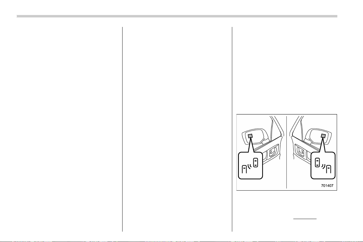
(422,1)
北米Model "A1700BE-B" EDITED: 2017/ 10/ 11
rected, and the BSD/RCTA warning
indicator will disappear. However, if
the BSD/RCTA warning indicator
appears for a prolonged period of
time, have the system inspected at a
SUBARU dealer as soon as possible.
. The detectability of the radar sen-
sors is restricted. The BSD/RCTA de-
tection may be impaired and the system
may not operate properly under the
following conditions.
– When the rear bumper around the
radar sensors is distorted
– When ice, snow or mud adheres
to the rear bumper surface around
the radar sensors
– When stickers, etc. are affixed on
the areas of the radar sensors on
the rear bumper
– During adverse weather condi-
tions such as rain, snow or fog
– When driving on wet roads such
as snow-covered roads and through
puddles
. The radar sensors may not detect or
may have difficulty detecting the fol-
lowing vehicles and objects.
– Small motorcycles, bicycles, pe-
destrians, stationary objects on the
road or road side and etc.
– Vehicles with body shapes that
the radar may not reflect (vehicles
with lower body height such as
sports cars or a trailer with no
cargo)
– Vehicles that are not approaching
your vehicle even though they are in
the detection area (either on a
neighboring lane to the rear or be-
side your vehicle when reversing)
(The system determines the pre-
sence of approaching vehicles
based on data detected by the radar
sensors.)
– Vehicles traveling at significantly
different speeds
– Vehicles driving in parallel at al-
most the same speed as your vehi-
cle for a prolonged time
– Oncoming vehicles
– Vehicles in a lane beyond the
neighboring lane
– Vehicles travelling at a signifi-
cantly lower speed that you are
trying to overtake
. On a road with extremely narrow
lanes, the system may detect vehicles
driving in a lane next to the neighboring
lane.
& BSD/RCTA approach indica-
tor light/warning buzzer
While the BSD/RCTA is active, the follow-
ing item(s) will operate to alert the driver:
. The BSD/RCTA approach indicator
light (when there are vehicles in the
neighboring lanes).
. The BSD/RCTA approach indicator
light and warning buzzer (when a vehicle
is approaching from the left or right side
while reversing)
! BSD/RCTA approach indicator light
BSD/RCTA approach indicator light
It is mounted on each side of the outside
mirrors.
The indicator light will illuminate when a
vehicle approaching from behind is de-
Starting and operating/BSD/RCTA
7-60

(423,1)
北米Model "A1700BE-B" EDITED: 2017/ 10/ 11
tected.
The indicator light will flash to warn the
driver of dangers under the following
conditions.
. While the indicator light is illuminating, if
the turn signal lever is operated toward the
side in which this light turned on
. When reversing the vehicle while the
system detects a vehicle approaching
from either side
! BSD/RCTA a pproach indicator
light dimming function
When the headlights are on, the bright-
ness of the BSD/RCTA approach indicator
light will be reduced.
NOTE
. You may have difficulty seeing the
BSD/RCTA approach indicator light
under the following conditions.
– When sunlight shines directly on
it
– When the headlight beams from a
vehicle traveling behind shines di-
rectly on it
. While the illumination brightness
control dial is in the fully upward
position, even if the headlights are
turned on, the brightness of the BSD/
RCTA approach indicator light will not
be reduced. For details about the
illumination brightness control dial,
refer to “Illumination brightness con-
trol” F3-71.
! BSD/RCTA approach warning buz-
zer (only when reversing)
A warning buzzer sounds along with
flashing of the BSD/RCTA approach in-
dicator light to warn the driver of dangers.
You can change the setting of the warning
buzzer volume by operating the combina-
tion meter display (color LCD). For details,
refer to “BSD/RCTA” F3-43.
! Safety tips regarding the BSD/RCTA
approach indicator light/warning
buzzer
. In the following cases, operation of the
BSD/RCTA approach indicator light and
the warning buzzer may be delayed or the
system may fail to issue these warnings.
– When a vehicle moves to the neigh-
boring lane from a lane next to the
neighboring lane
– When you are driving on a steep
incline or on repeated sharp uphill and
downhill grades
– When you are going beyond a pass
– When both your vehicle and a
vehicle driving on a neighboring lane
are driving on the far side of each lane.
– When several narrowly-spaced ve-
hicles are approaching in a row
– In low radius bends (tight bends or
when making turns at an intersection)
– When there is a difference in height
between your lane and the neighboring
lane
– Immediately after the BSD/RCTA is
activated by pressing the BSD/RCTA
OFF switch
– Immediately after the shift lever/
select lever is shifted to the “R” position
– When extremely heavy cargo is
loaded in the trunk
. During reversing, operation of the BSD/
RCTA approach indicator light and the
warning buzzer may be delayed or the
system may fail to issue these warnings
under the following conditions.
– When backing out of an angled
parking space
– When a large-sized vehicle is
parked next to your vehicle (That
vehicle prevents the propagation of
radar waves.)
– When reversing on sloped roads
– When reversing at a high speed
– CONTINUED –
Starting and operating/BSD/RCTA
7-61
7
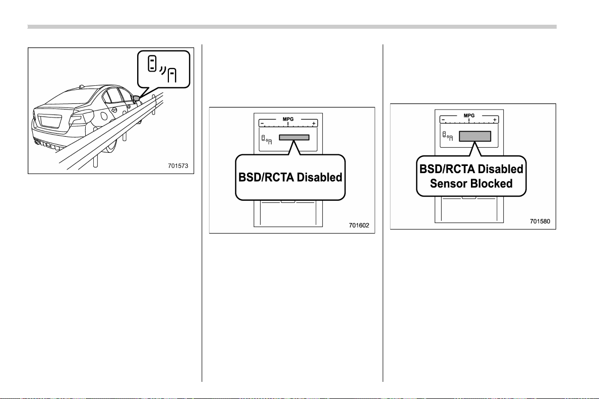
(424,1)
北米Model "A1700BE-B" EDITED: 2017/ 10/ 11
. The BSD/RCTA approach indicator
light may illuminate when driving close to
solid objects on the road or road side (such
as guardrails, tunnels and sidewalls).
. The BSD/RCTA approach indicator
light may flash when turning at an inter-
section in urban areas or multilane inter-
sections.
. The BSD/RCTA approach indicator
light may flash and the warning buzzer
may sound if a building or a wall is in the
reversing direction.
. In the following cases, the system may
detect a vehicle driving two lanes away
from your vehicle.
– When your vehicle drives on the
near side of its lane from the corre-
sponding vehicle
– When the vehicle driving two lanes
away drives on the near side of its lane
from your vehicle
& BSD/RCTA warning indicator
! System temporary stop indicator
System temporary stop indicator
This indicator appears when the system is
used under the following conditions.
. Extremely high or low temperatures
. When abnormal voltage exists for the
vehicle battery
. When the radar sensor is significantly
misaligned
Once these conditions are corrected, the
system will recover from the temporary
stop condition and the indicator will dis-
appear.
If the indicator remains displayed for a
prolonged time, ha ve the system in-
spected at a SUBARU dealer.
! System temporary stop indicator
due to reduced radar sensitivity
System temporary stop indicator due to
reduced radar sensitivity
This indicator appears when the detect-
ability of the radar sensors is reduced.
Once the condition is corrected, the
system will recover from the temporary
stop condition and the indicator will dis-
appear.
If the indicator remains displayed for a
prolonged time, ha ve the system in-
spected at a SUBARU dealer.
Starting and operating/BSD/RCTA
7-62
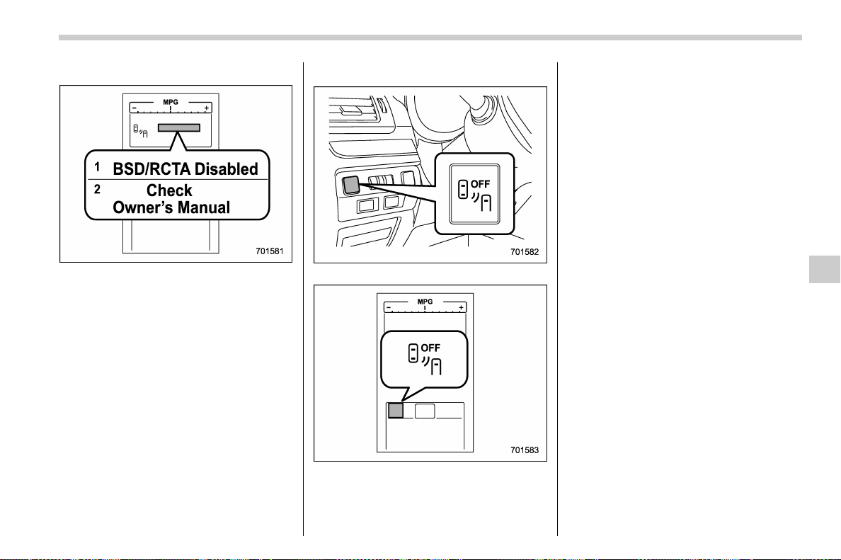
(425,1)
北米Model "A1700BE-B" EDITED: 2017/ 10/ 11
! System malfunction indicator
System malfunction indicator
1) At first, this message will appear
2) Then this message will appear
This indicator appears when a malfunction
occurs in the system. Contact a SUBARU
dealer and have the system inspected.
& BSD/RCTA OFF switch
BSD/RCTA OFF switch
BSD/RCTA OFF indicator
Press the BSD/RCTA OFF switch to
deactivate the BSD/RCTA. Then t he
BSD/RCTA OFF indicator light will appear
on the combination meter display (color
LCD).
Press the switch again to activate the BSD/
RCTA. The BSD/RCTA OFF indicator
disappears.
NOTE
. In the following cases, press the
BSD/RCTA OFF switch to deactivate
the system. The system may not oper-
ate properly due to blocked radar
waves.
– When a bicycle carrier or other
item is fitted to the rear of the
vehicle
– When using a chassis dynam-
ometer or free roller device, etc.
– When running the engine and
making the wheels rotate while
lifting up the vehicle
. If you turn the ignition switch to the
“LOCK”/“OFF” position, the last known
status of the system is maintained. For
example, if you turn the ignition switch
to the “LOCK”/“OFF” position with the
BSD/RCTA deactivated, the BSD/RCTA
remains deactivated the next time you
turn the ignition switch to the “ON”
position.
– CONTINUED –
Starting and operating/BSD/RCTA
7-63
7
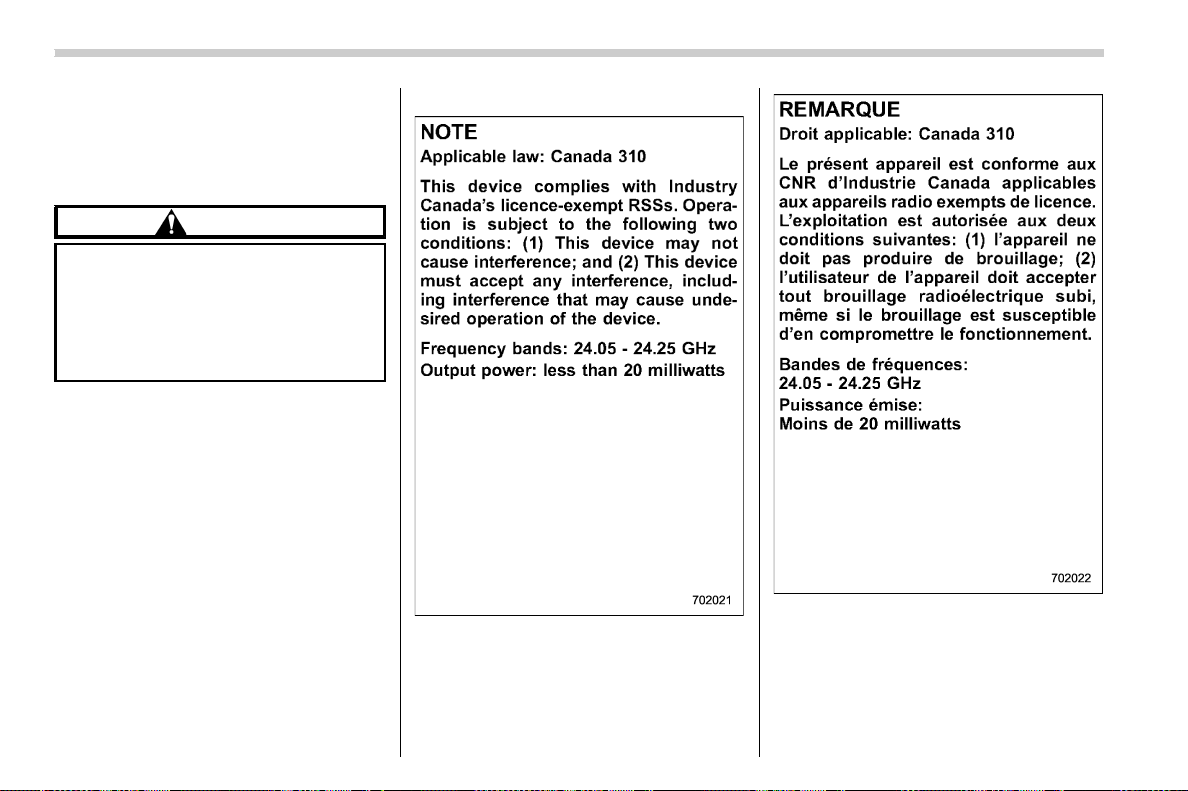
(426,1)
北米Model "A1700BE-B" EDITED: 2017/ 10/ 11
& Certification for the BSD/
RCTA
. U.S.-spec. models
FCC ID: OAYSRR3A
CAUTION
FCC WARNING
Changes or modifications not ex-
pressly approved by the party re-
sponsible for compliance could void
the user’s authority to operate the
equipment.
This device complies with part 15 of the
FCC Rules. Operation is subject to the
following two conditions: (1) This device
may not cause harmful interference, and
(2) this device must accept any interfer-
ence received, including interference that
may cause undesired operation.
. Canada.-spec. models
Starting and operating/BSD/RCTA
7-64
(427,1)
北米Model "A1700BE-B" EDITED: 2017/ 10/ 11
. Mexico-spec. models
Certificado de homologacion:
RLVCOSR15-0442
Continental SRR3-A
ATTENTION:
Cofetel requires that their notice is printed
on the user manual in Spanish with the
exact words above.
If the user manual in Spanish does not
contain the notice it will not be accepted by
Cofetel and they will not grant NOM-121
certificate.
Moreover, it is important to tell your
customer that Cofe tel ins pectors are
checking the user manual in Spanish that
is included with the product. If the manual
does not contain Cofetel notice as above,
they will put a penalty to the importer and
distributor.
& Handling of radar sensors
Radar sensors
The radar sensors, one on each side of the
vehicle, are mounted inside the rear
bumper.
CAUTION
To ensure correct operation of the
BSD/RCTA, observe the following
precautions.
– Always keep the bumper surface
near the radar sensors clean.
– Do not affix any stickers or other
items on the bumper surface near
the radar sensors.
– Do not modify the bumper near
the radar sensors.
– Do not paint the bumper near the
radar sensors.
– Do not expose the bumper near
the radar sensors to strong im-
pacts. If a sensor becomes mis-
– CONTINUED –
Starting and operating/BSD/RCTA
7-65
7
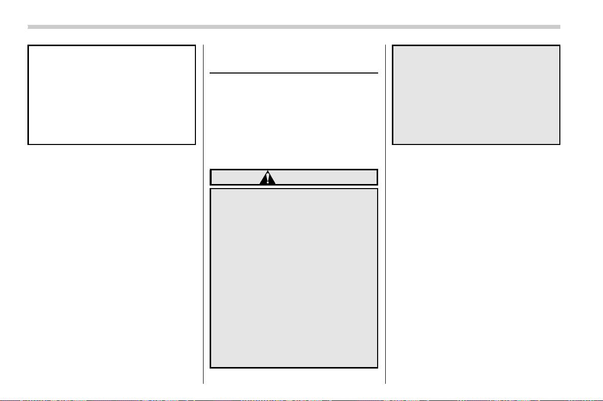
(428,1)
北米Model "A1700BE-B" EDITED: 2017/ 10/ 11
aligned, a system malfunction
may occur, including the inability
to detect vehicles entering the
detection areas. If any strong
shock is applied to the bumper,
be sure to contact your SUBARU
dealer for inspection.
– Do not disassemble the radar
sensors.
NOTE
If the radar sensors require repair or
replacement, or the bumper area
around the radar sensors requires
repair, paintwork or replacement, con-
tact your SUBARU dealer for assis-
tance.
Reverse Automatic Braking
System (if equipped)
Reverse Automatic Braking is a system
designed to help avoid collisions or reduce
collision damage when reversing the
vehicle. If a wall or an obstacle is detected
in the reversing direction, the system will
notify the driver with a warning sound and
may activate the vehicle’s brakes auto-
matically.
WARNING
. Reverse Automatic Braking is not
a system intended to replace the
driver’s responsibility to check
surrounding areas for vehicles or
obstacles to avoid a collision.
. The driver is responsible for driv-
ing safely. Always be sure to
check the surroundings visually
when reversing the vehicle.
. There are some cases in which
the vehicle cannot avoid colli-
sion, because the system opera-
tion has limitations. The warning
sound or automatic braking may
be delayed or may not operate at
all even when an obstacle is
present.
. The system is not designed to
detect people (including chil-
dren), animals or other moving
objects.
. Depending on the vehicle condi-
tion or the surrounding environ-
ment, the sonar sensor’s ability
to detect objects may become
unstable.
NOTE
The Reverse Automatic Braking Sys-
tem records and stores the following
data when automatic braking operates.
It does not record conversations, per-
sonal information or other audio data.
. Distance from the object
. Vehicle speed
. Accelerator pedal operation status
. Brake pedal operation status
. Select lever position
. Outside temperature
. The sensitivity setting of the sonar
sensors
SUBARU and third parties con-
tracted by SUBARU may acquire
and use the recorded data for the
purpose of vehicle research and
development. SUBARU and third
parties contracted by SUBARU will
Starting and operating/Reverse Automatic Braking System
7-66
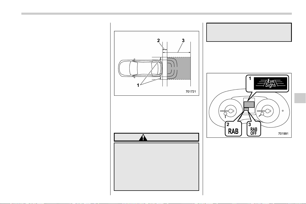
(429,1)
北米Model "A1700BE-B" EDITED: 2017/ 10/ 11
not disclose or provide the acquired
data to any other third party except
under the following conditions.
– The vehicle owner has given his/
her consent.
– The disclosure/provision is
based on a court order or other
legally enforceable request.
– Data that has been modified so
that the user and vehicle cannot be
identified is provided to a research
institution for statistical processing
or similar purposes.
& Reverse Automatic Braking
System overview
The system detects objects using sonar
sensors installed in the rear bumper. If the
system determines a possible collision
with an object in the reversing direction,
automatic deceleration will be activated.
Also, beeping sounds will activate. If the
vehicle is further reversed, automatic hard
braking will be applied and a continuous
beeping sound will activate.
! Detecting range
1) Detecting range (width): Approximately 6
in (15 cm) outside of the vehicle width
2) Range that the system cannot detect:
Approximately 20 in (50 cm) behind the
rear of the vehicle
3) Detecting range (length): Approximately
5 ft (1.5 m) from the rear of the vehicle
WARNING
If your vehicle is trapped on a rail-
road crossing and you are trying to
escape by reversing through the
crossing gate, the system may re-
cognize the crossing gate as an
obstacle and the brakes may acti-
vate. In this case, remain calm and
either continue to depress the accel-
erator pedal or cancel the system. To
cancel the system, refer to “Cancel-
ing the Reverse Automatic Braking
system operation” F7-74.
& Operating conditions
The Reverse Automatic Braking system
will operate when all of the following
conditions are met.
1) EyeSight warning indicator
2) RAB warning indicator
3) RAB OFF indicator
. Theignitionswitchisinthe“ON”
position
. The EyeSight warning indicator is off
. The RAB warning indicator is off
. HALT (RAB OFF) indicator is off
. The Reverse Automatic Braking sys-
– CONTINUED –
Starting and operating/Reverse Automatic Braking System
7-67
7

(430,1)
北米Model "A1700BE-B" EDITED: 2017/ 10/ 11
tem is set to on
. The select lever is in the “R” position
. The vehicle speed is between 1 to 9
mph (1.5 to 15 km/h)
NOTE
. When the Reverse Automatic Brak-
ing fail indicator is illuminated, the
Reverse Automatic Braking system
cannot be operated. Promptly contact
a SUBARU dealer to have the system
inspected.
. When the Reverse Automatic Brak-
ing system OFF indicator is illumi-
nated, the Reverse Automatic Braking
system cannot be operated.
. In the following cases, the system
may not be able to properly detect an
obstacle. Promptly contact a SUBARU
dealer to have the system inspected.
– A sticker, paint, or a chemical is
applied to the sonar sensors or the
rear bumper near the sonar sensor
– The rear bumper is modified
– The rear bumper has been re-
moved and reattached
– The ground clearance is changed
due to the vehicle’s loading condi-
tion or modification
– Ice, snow or mud is adhered to
the sonar sensors or the rear bum-
per near the sonar sensor
– The rear bumper is exposed to
strong impact, or the rear bumper is
deformed
. On a steep hill, the system’s auto-
matic braking ability will be reduced.
. The system is designed to avoid
collisions by automatic hard braking
when the vehicle’s reversing speed is
less than approximately 3 mph (5 km/h).
However, the system does not guaran-
tee that the vehicle will be able to avoid
collisions in any situation.
. If the vehicle is reversed at an
extremely slow speed, the driver ’s
operation may be prioritized. In this
case, automatic braking will not oper-
ate.
. The system may not be able to detect
the following objects
– Sharp or thin objects such as
poles, fences and ropes which may
not reflect the sound wave emitted
from the sonar sensor
– Objects that are too close to the
rear bumper when the select lever is
set to the “R” position
– Objects with a surface which may
not reflect the sound wave emitted
from the sonar sensor such as a
chain link fence.
. Objects the system is not designed
to detect
– Pedestrians
– Moving objects including moving
vehicles
– Objects which absorb sound
waves such as cloth or snow
– Objects whose surface has a
diagonal angle
– Objects that are low to the ground
such as parking blocks
– Objects that are high above the
ground such as objects hanging
from above
. The system may not be able to
properly detect objects or may cause
a system malfunction when the follow-
ing conditions exist
High frequency sound from other
sources are nearby
– Horn sound from another vehicle
– Engine sound from other vehi-
cles
– Sound of an air brake
– Vehicle detection equipment or a
sonar from another vehicle
– A sound wave with a frequency
similar to the vehicle’s system is
transmitted nearby
–
A vehicle equipped with the same
system is reversing toward your
reversing direction
Starting and operating/Reverse Automatic Braking System
7-68
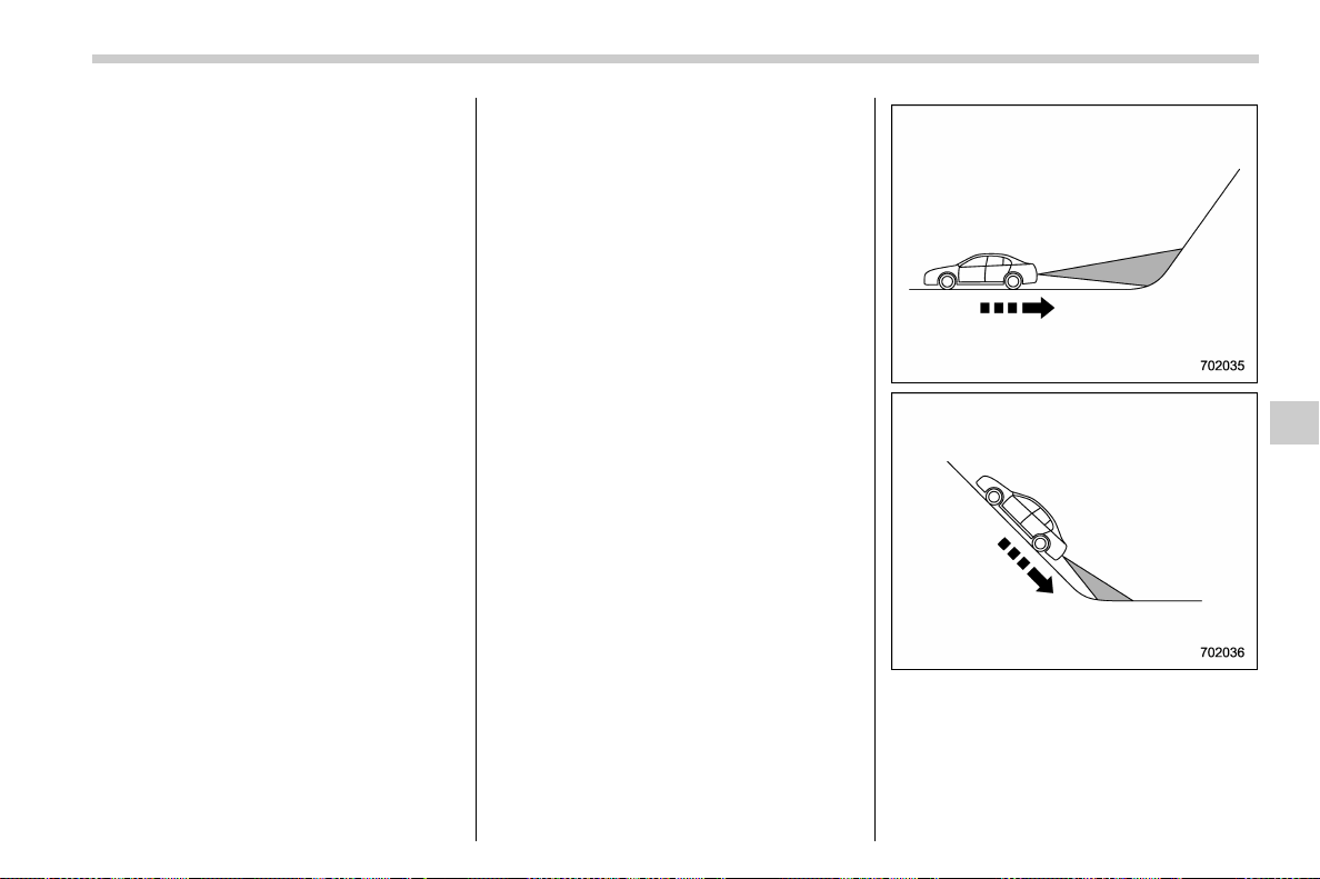
(431,1)
北米Model "A1700BE-B" EDITED: 2017/ 10/ 11
Weather conditions
– Extremely high or extremely low
temperatures in which the area near
the sonar sensor becomes too hot
or too cold to operate
– The sonar sensors or the rear
bumper near the sonar sensors is
exposed to heavy rain or a signifi-
cant amount of water
– Fog, snow or sandstorm, etc.
– Air is moving rapidly such as
when a strong wind is blowing
Parts attached to the rear bumper
near the sonar sensor
– Commercial electronic parts (fog
light, fender pole, radio antenna) or
commercial attachment parts (trai-
ler hitch, bicycle carrier, bumper
guard) are attached
– Parts that emit high frequency
sound, such as a horn or speaker,
are attached
Vehicle conditions
– The vehicle is significantly in-
clined
– The ground clearance is signifi-
cantly reduced due to the vehicle’s
loading condition, etc.
– When the sonar sensor is mis-
aligned due to a collision or an
accident
Surrounding environment
– A cloth banner, flag, hanging
branch or railroad cross ing bars
are present in the reversing direc-
tion
– When reversing on a gravel or
grassy area
– When reversing in an area where
objects or walls are adjacent to the
vehicle such as narrow tunnels,
narrow bridges, narrow roads or
narrow garages
– Wheel tracks or a hole is present
in the gro und of the reversin g
direction
– When reversing over a drainage
cover (grate cover)
– The path of the reversing direc-
tion is inclined such as on a steep
uphill
– A curb is present in the reversing
direction
– When reversing downhill
– CONTINUED –
Starting and operating/Reverse Automatic Braking System
7-69
7
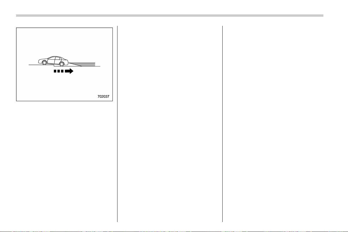
(432,1)
北米Model "A1700BE-B" EDITED: 2017/ 10/ 11
– When reversing on an uneven
road
. In circumstances such as the follow-
ing, it may not be possible to avoid a
collision even when the system oper-
ates normally.
– Roads are slippery.
– The tire air pressure is not cor-
rect.
– The tires have become worn.
– Tire chains are installed.
– Tires which are not the desig-
nated size are installed.
– Emergency repairs were per-
formed using a puncture repair kit.
– The suspension was modified.
– Vehicle driving is unstable due to
accident or malfunction.
– The brake warning light is illumi-
nated.
& Reverse Automatic Braking
System operation
When the Reverse Automatic Braking
System is in operation, the range between
the vehicle and the detected object will be
indicated on the multi-function display
(color LCD). Also, warning sounds will
activate in 3 levels to warn the driver of a
potential collision.
While the RAB is operating, a warning
message is displayed on the multi-function
display (color LCD) and the combination
meter display (color LCD).
Starting and operating/Reverse Automatic Braking System
7-70
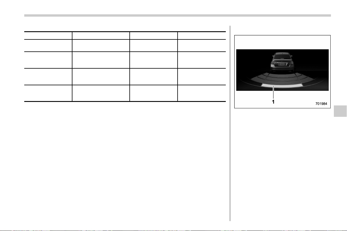
(433,1)
北米Model "A1700BE-B" EDITED: 2017/ 10/ 11
Guideline of detecting range
Alert level Range of detected object* Distance indicator Alarm pattern
Long proximity (ob-
ject detected)
35 inches (90 cm) or more Green No warning sound
Medium proximity
alert (approaching the
object)
28 to 35 inches (70 to 90
cm)
Yellow + Green Short beeps
Close proximity alert
(approaching closer
to the object)
20 to 28 inches (50 to 70
cm)
Orange + Yellow +
Green
Rapid short beeps
Closest proximity
alert (too close to the
object)
20 inches (50 cm) or less
Red + Orange +
Yellow + Green
Continuous beep
*: Range of detection may vary depending on the environmental condition.
! Obstacle detected and Alert level
Long proximity alert (object detected)
1) Green: 35 inches (90 cm) or more
– CONTINUED –
Starting and operating/Reverse Automatic Braking System
7-71
7
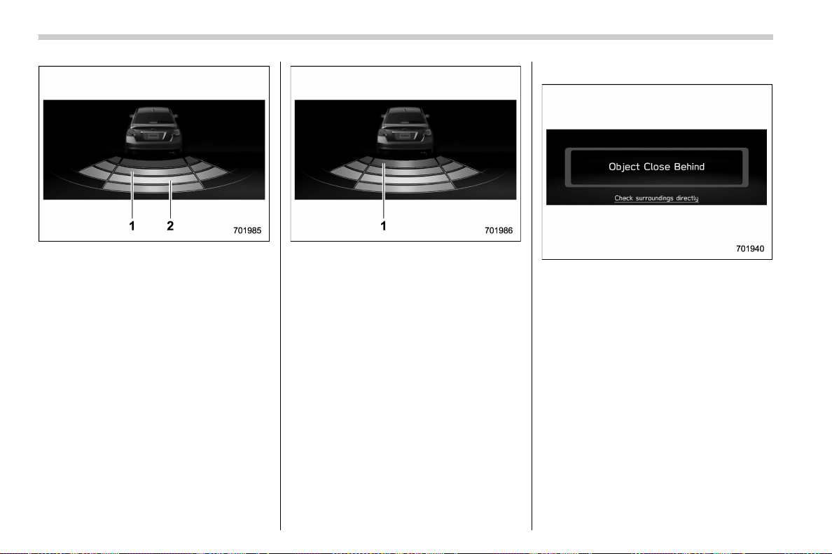
(434,1)
北米Model "A1700BE-B" EDITED: 2017/ 10/ 11
Medium and close proximity alert (ap-
proaching the object and approaching
closer to the object)
1) Orange: 20 to 28 inches (50 to 70 cm)
2) Yellow: 28 to 35 inches (70 to 90 cm)
Closest proximity alert (too close to the
object)
1) Red: 20 inches (50 cm) or less
When an object is detected in the rever-
sing direction, the range of detected object
will be shown on the multi-function display
(color LCD).
A warning alarm will sound and, depend-
ing on the speed, either torque control to
generate engine braking or automatic
braking will be applied.
! Object close behind warning
Automatic braking warning
If the vehicle continues to go in reverse,
the system may determine the risk of
collision with the object. In this case, short
warning beeps or continuous warnin g
beeps will sound and either strong auto-
matic braking or torque control will be
applied to prevent collision.
At this time, a warning message is also
displayed on the combination meter dis-
play (color LCD).
Starting and operating/Reverse Automatic Braking System
7-72
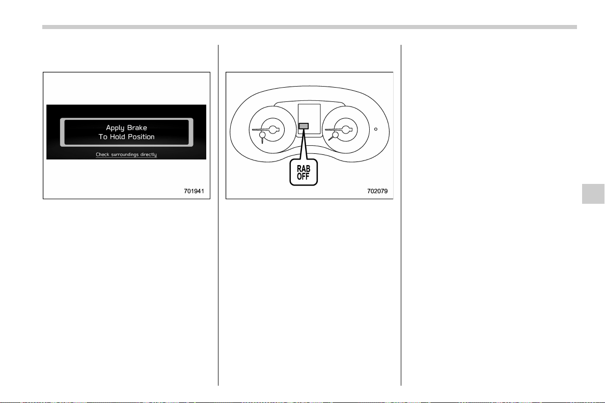
(435,1)
北米Model "A1700BE-B" EDITED: 2017/ 10/ 11
! When the vehicle is being stopped
by the system
Depress brake pedal warning
Make sure to depress the brake pedal
once the vehicle has been stopped by
automatic braking. Until the brake pedal is
depressed, a message will be displayed
on the multi-function display (color LCD)
and the continuous beep will remain
sounding.
At this time, a warning message is also
displayed on the combination meter dis-
play (color LCD).
! After the vehicle is stopped by the
system
1) Reverse Automatic Braking system OFF
indicator
After the brake pedal is depressed, the
Reverse Automatic Braking system OFF
indicator will illuminate and the system will
stop operating temporarily. The Reverse
Automatic Braking system OFF indicator
will turn off when the select lever is shifted
to a position other than the “R” position.
The system will operate again the next
time the select lever is shift ed to “R”
position.
NOTE
. After the vehicle has been stopped
by the Reverse Automatic Braking
system, brake control is released and
the electronic parking brake operates
in the following cases. For details about
releasing the parking brake, refer to
“Electronic parking brake (models with
electronic parking brake system)” F7-
43.
– 2 minutes pass after the vehicle
is stopped
– Any door is opened
– The EyeSight system malfunc-
tions
– The EyeSight system stops tem-
porarily
– The Reverse Automatic Braking
system stops temporarily
. The Reverse Automatic Braking sys-
tem may stop operating temporarily in
the following cases and the Reverse
Automatic Braking system OFF indica-
tor will illuminate.
– Ice, snow or mud is adhered to
the sonar sensors or the rear bum-
per near the sonar sensor
– Objects are too close to the rear
bumper when the select lever is set
to the “R” position
– The system detects sounds of a
– CONTINUED –
Starting and operating/Reverse Automatic Braking System
7-73
7
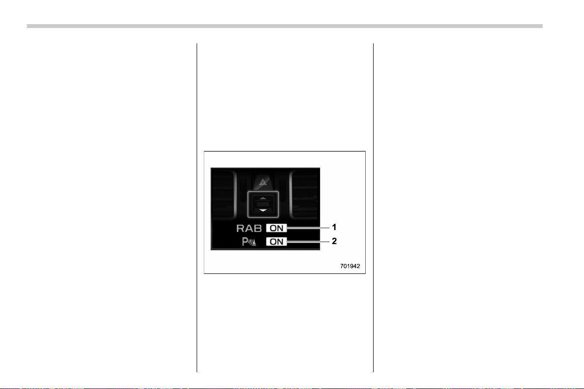
(436,1)
北米Model "A1700BE-B" EDITED: 2017/ 10/ 11
similar frequency to the RAB sonar.
& Canceling the Reverse Auto-
matic Braking system opera-
tion
The Reverse Automatic Braking system
can be temporarily cancelled by any of the
following operations.
. depressing the brake pedal
*
. depressing the accelerator pedal
*
. depressing and holding the accelerator
pedal (in this case, limited acceleration will
be canceled and the vehicle will continue
reversing.)
. shifting the select lever to a position
other than the “R” position
*: while the vehicle is stopped by the
automatic braking
NOTE
The system will be cancelled if the
object is no longer detected.
& Reverse Automatic Braking
system ON/OFF setting
While the select lever is shifted to the “R”
position, the below functions of the Re-
verse Automatic Braking system can be
set by operating the multi-function display
(color LCD).
For details about how to operate the multi-
function display (color LCD), refer to
“Basic operation” F3-46.
1) ON/OFF setting of Reverse Automatic
Braking
2) ON/OFF setting of the object detection
warning sound
When the Reverse Automatic Braking
system is turned off, the RAB OFF
indicator will illuminate.
NOTE
The Reverse Automatic Braking sys-
tem settings that are changed by the
multi-function display (color LCD) will
be restored to default (ON setting) the
next time the select lever is shifted to
“R” position.
Also, the following settings can be chan-
ged by operating the combination meter
display (color LCD).
. Warning volume
. Sonar audible alarm ON/OFF
For details, refer to “RAB (models with the
EyeSight system)” F3-43.
Starting and operating/Reverse Automatic Braking System
7-74
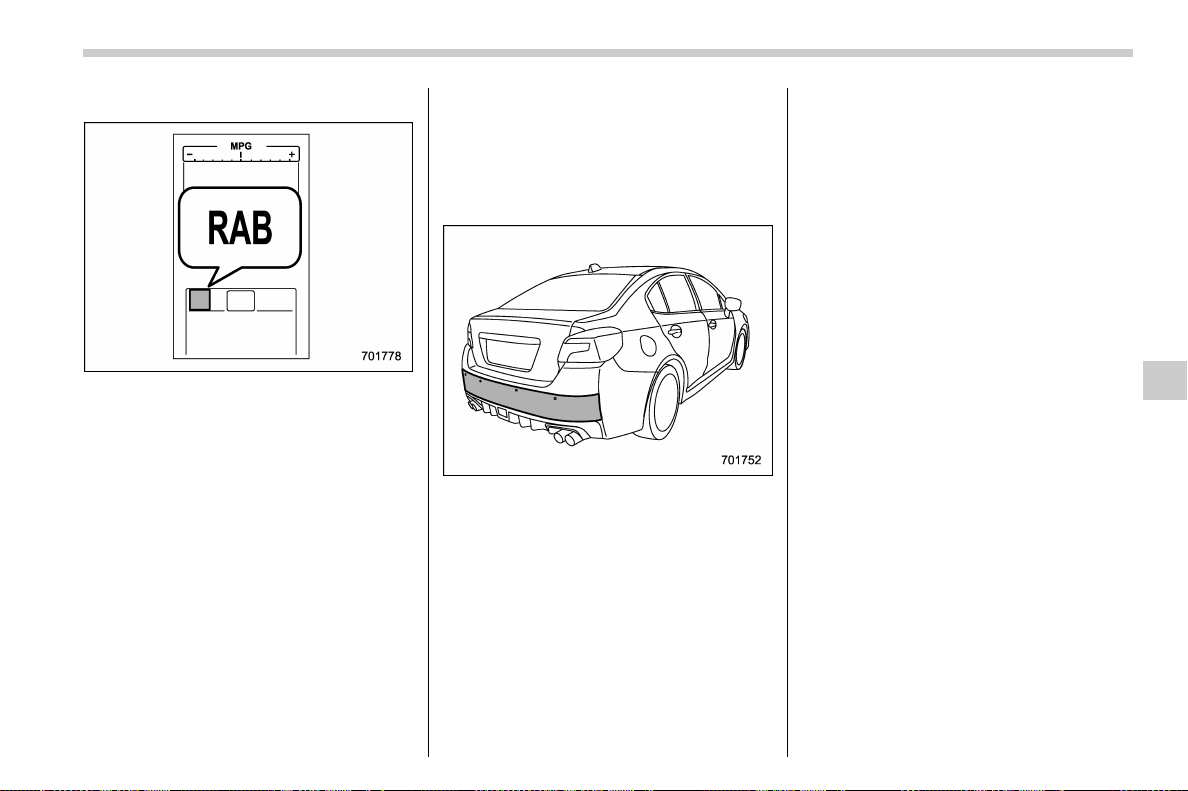
(437,1)
北米Model "A1700BE-B" EDITED: 2017/ 10/ 11
& RAB warning indicator
If the Reverse Automatic Braking System
malfunctions, the above indicator illumi-
nates on the combination meter. Contact
the nearest SUBARU dealer for details.
& Handling of the sonar sen-
sors
The 4 sonar sensors are located in the rear
bumper. To ensure the proper operation of
the Reverse Automatic Braking system,
observe the following precautions.
. Do not affix any stickers or other items
on the sonar sensors or the bumper
surface near the sonar sensors.
. Always keep the sonar sensors and the
rear bumper surface near the sonar
sensors clean.
. Do not modify the rear bumper.
. Do not paint the bumper near the sonar
sensors.
. Do not apply strong impacts to the rear
bumper near the sonar sensors. If a sensor
becomes misaligned, a system malfunc-
tion may occur, including inability to detect
objects in the reversing direction. If any
strong impact is applied to the rear
bumper, contact a SUBARU dealer to
have the system inspected.
. Do not disassemble the sonar sensors.
NOTE
If the sonar sensors require repair or
replacement, or if the area of the rear
bumper n ear the sonar sensors re-
quires repair, paintwork or replace-
ment, contact your SUBARU dealer for
assistance.
Starting and operating/Reverse Automatic Braking System
7-75
7

Black plate (2,1)
Model "ALL_MODEL_MEMO" EDITED: 2007/ 6/ 22
Left Page
————————————————————————————————————————
————————————————————————————————————————
————————————————————————————————————————
————————————————————————————————————————
————————————————————————————————————————
————————————————————————————————————————
————————————————————————————————————————
————————————————————————————————————————
————————————————————————————————————————
————————————————————————————————————————
————————————————————————————————————————
————————————————————————————————————————
————————————————————————————————————————

(441,1)
北米Model "A1700BE-B" EDITED: 2017/ 10/ 11
New vehicle break-in driving – the first 1,000
miles (1,600 km) ................................................... 8-2
Fuel economy hints ................................................ 8-2
Engine exhaust gas (carbon monoxide) ............... 8-2
Catalytic converter.................................................. 8-3
Periodic inspections ............................................... 8-4
Driving in foreign countries ................................... 8-4
Driving tips for AWD models ................................. 8-5
Driving precaution .................................................. 8-6
Winter driving.......................................................... 8-6
Operation during cold weather ............................... 8-6
Driving on snowy and icy roads ............................. 8-8
Corrosion protection.............................................. 8-9
Snow tires .............................................................. 8-9
Tire chains ...........................................................8-10
Rocking the vehicle .............................................. 8-10
Loading your vehicle.............................................8-11
Vehicle capacity weight ........................................ 8-12
GVWR and GAWR (Gross Vehicle Weight Rating
and Gross Axle Weight Rating) .......................... 8-12
Precautions for TYPE RA ......................................8-13
Roof molding and crossbar (if equipped) .............. 8-13
Trailer towing ........................................................ 8-14
Rear wing (TYPE RA) ........................................... 8-15
Adjusting the angle of the rear wing ..................... 8-15
CFRP (Carbon Fiber Reinforced Plastic) parts .......8-16
Driving tips
8
(442,1)
北米Model "A1700BE-B" EDITED: 2017/ 10/ 11
New vehicle break-in driving –
the first 1,000 miles (1,600 km)
The performance and long life of your
vehicle are dependent on how you handle
and care for your vehicle while it is new.
Follow these instructions during the first
1,000 miles (1,600 km):
. Do not race the engine. And do not
allow engine speed to exceed 4,000 rpm
except in an emergency.
. Do not drive at one constant engine or
vehicle speed, either fast or slow.
. Avoid starting suddenly and rapid ac-
celeration, except in an emergency.
. Avoid hard braking, except in an emer-
gency.
The same break-in procedures should be
applied to an overhauled engine, newly
mounted engine or when brake pads or
brake linings are replaced with new ones.
Fuel economy hints
The following suggestions will help to save
fuel.
. Select the proper gear position for the
speed and road conditions.
. Avoid sudden acceleration or decelera-
tion. Always accelerate gently until you
reach the desired speed. Then try to
maintain that speed for as long as possi-
ble.
. Do not pump the accelerator and avoid
racing the engine.
. Avoid unnecessary engine idling.
. Keep the engine properly tuned.
. Keep the tires inflated to the correct
pressure shown on the tire placard, which
is located under the door latch on the
driver’s side. Low pressure will increase
tire wear and fuel consumption.
. Use the air conditioner only when
necessary.
. Keep the front and rear wheels in
proper alignment.
. Avoid carrying unnecessary luggage or
cargo.
. The indication of the ECO gauge shows
a reference for saving fuel. For details,
refer to “ECO gauge” F3-12.
Engine exhaust gas (carbon
monoxide)
WARNING
. Never inhale engine exhaust gas.
Engine exhaust gas contains
carbon monoxide, a colorless
and odorless gas which is dan-
gerous, or even lethal, if inhaled.
. Always properly maintain the en-
gine exhaust system to prevent
engine exhaust gas from entering
the vehicle.
. Never run the engine in a closed
space, such as a garage, except
for the brief time needed to drive
the vehicle in or out of it.
. Avoid remaining in a parked ve-
hicle for a lengthy time while the
engine is running. If that is un-
avoidable, then use the ventila-
tion fan to force fresh air into the
vehicle.
. Always keep the front ventilator
inlet grille free from snow, leaves
or other obstructions to ensure
that the ventilation system al-
ways works properly.
. If at any time you suspect that
Driving tips/New vehicle break-in driving – the first 1,000 miles (1,600 km)
8-2
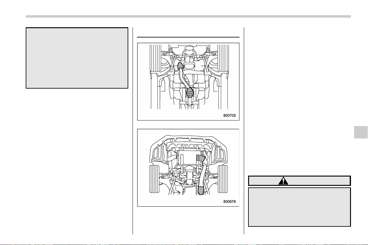
(443,1)
北米Model "A1700BE-B" EDITED: 2017/ 10/ 11
exhaust fumes are entering the
vehicle, have the problem
checked and corrected as soon
as possible. If you must drive
under these conditions, drive
only with all windows fully open.
. Keep the trunk lid closed while
driving to prevent exhaust gas
from entering the vehicle.
NOTE
Due to the expansion and contraction
of the metals used in the manufacture
of the exhaust system, you may hear a
crackling sound coming from the ex-
haust system for a short time after the
engine has been shut off. This sound is
normal.
Catalytic converter
STI
Except STI
The catalytic converter is installed in the
exhaust system. It serves as a catalyst to
reduce HC, CO and NOx in exhaust gases,
thus providing cleaner exhaust.
To avoid damage to the catalytic converter:
. Use only unleaded fuel. Even a small
amount of leaded fuel will damage the
catalytic converter.
. Never start the engine by pushing or
pulling the vehicle.
. Avoid racing the engine.
. Never turn off the ignition switch while
the vehicle is moving.
. Keep your engine tuned-up. If you feel
the engine running rough (misfiring, back-
firing or inco mplete combustion), have
your vehicle checked and repaired by an
authorized SUBARU dealer.
. Do not apply undercoating or rust
prevention treatment to the heat shield of
catalytic converter and the exhaust sys-
tem.
. Do not drive with an extremely low fuel
level.
WARNING
. Avoid fire hazards. Do not drive
or park the vehicle anywhere
near flammable materials (e.g.,
grass, paper, rags or leaves),
because the catalytic converter
operates at very high tempera-
– CONTINUED –
Driving tips/Catalytic converter
8-3
8

(444,1)
北米Model "A1700BE-B" EDITED: 2017/ 10/ 11
tures.
. Keep everyone and flammable
materials away from the exhaust
pipe while the engine is running.
The exhaust gas is very hot.
Periodic inspections
To keep your vehicle in the best condition
at all times, always have the recom-
mended maintenance services listed in
the maintenance schedule in the “War-
ranty and Maintenance B ooklet” per-
formed at the specified time or mileage
intervals.
Driving in foreign countries
When planning to use your vehicle in
another country:
. Confirm the availability of the correct
fuel. Refer to “Fuel requirements” F7-3.
. Comply with all regulations and require-
ments of each country.
Driving tips/Periodic inspections
8-4
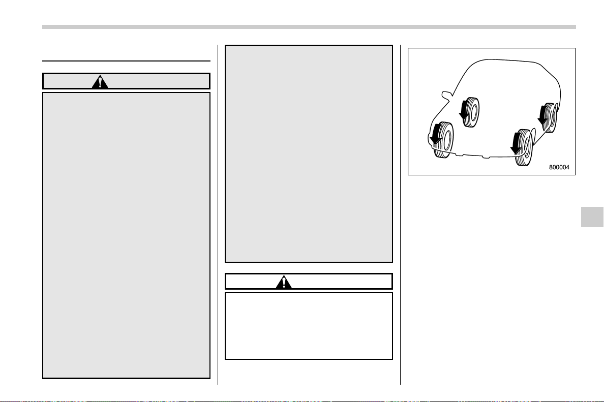
(445,1)
北米Model "A1700BE-B" EDITED: 2017/ 10/ 11
Driving tips for AWD models
WARNING
. Always maintain a safe driving
speed according to the road and
weather conditions in order to
avoid having an accident on a
sharp turn, during sudden brak-
ing or under other similar condi-
tions.
. Always use the utmost care in
driving – overconfidence be-
cause you are driving an All-
Wheel Drive vehicle could easily
lead to a serious accident.
. When you replacing or installing
tire(s), all four tires must be the
same for following items.
(a) Size
(b) Circumference
(c) Speed symbol
(d) Load index
(e) Construction
(f) Manufacturer
(g) Brand (tread pattern)
(h) Degrees of wear
For the items (a) to (d), you must
obey the specification that is
printed on the tire placard. The
tire placard is located on the
bottom of driver’s door pillar.
If all of four tires are not the same
for items (a) to (h), there is a
possibility that serious mechan-
ical damage could occur to the
drive train of your car, and affect
the following.
— Ride
— Handling
— Braking
— Speedometer/Odometer
calibration
— Clearance between the body
and tires
It also may be dangerous and
lead to loss of vehicle control,
and it can lead to an accident.
CAUTION
If you use a temporary spare tire to
replace a flat tire, be sure to use the
original temporary spare tire stored
in the vehicle. Using other sizes may
result in severe mechanical damage
to the drive train of your vehicle.
All-Wheel Drive distributes the engine
power to all four wheels. AWD models
provide better traction when driving on
slippery, wet or snow-covered roads and
when moving out of mud, dirt and sand. By
shifting power between the front and rear
wheels, SUBARU AWD can also provide
added traction during acceleration and
added engine braking force during decel-
eration.
Therefore, your SUBARU AWD vehicle
may handle differently than an ordinary
two wheel drive vehicle and it contains
some features unique to AWD. For safety
purposes as well as to avoid damaging the
AWD system, you should keep the follow-
ing tips in mind.
. An AWD model is better able to climb
steeper roads under snowy or slippery
– CONTINUED –
Driving tips/Driving tips for AWD models
8-5
8

(446,1)
北米Model "A1700BE-B" EDITED: 2017/ 10/ 11
conditions than a two wheel drive vehicle.
There is little difference in handling, how-
ever, during extremely sharp turns or
sudden braking. Therefore, when driving
down a slope or turning corners, be sure to
reduce your speed and maintain an ample
distance from other vehicles.
. Always check the cold tire pressure
before starting to drive. The recommended
tire pressure is provided on the tire
placard, which is located under the door
latch on the driver’s side.
. Frequent driving of an AWD vehicle
under hard-driving conditio ns such as
steep hills or dusty roads will necessitate
more frequent replacement of the follow-
ing items than that specified in the “War-
ranty and Maintenance Booklet”.
– Engine oil
– Brake fluid
– Rear differential gear oil
– Manual transmission oil (MT mod-
els)
– Continuously variable transmission
fluid (CVT models)
– Front differential gear oil (CVT
models)
. There are some precautions that you
must observe when towing your vehicle.
For detailed information, refer to “ Towing”
F9-21.
Driving precaution
Water entering the engine air intake or the
exhaust pipe or water splashing onto
electrical parts may damage your vehicle
and may cause it to stall. Never attempt to
drive through rushing water; regardless of
its depth, it can wash away the ground
from under your tires, resulting in possible
loss of traction and even vehicle rollover.
Winter driving
& Operation during cold weath-
er
Carry some emergency equipment, such
as a window scraper, a bag of sand, flares,
a small shovel and jumper cables.
Check the battery and cables. Cold tem-
peratures reduce battery capacity. The
battery must be in good condition to
provide enough power for cold winter
starts.
It normally takes longer to start the engine
in very cold weather conditions. Use an
engine oil of a proper grade and viscosity
for cold weather. Using heavy summer oil
will make it harder to start the engine.
Keep the door locks from freezing by
squirting them with deicer or glycerin.
Forcing a frozen door open may damage
or separate the rubber weather strips
around the door. If the door is frozen, use
hot water to melt the ice, and afterwards
thoroughly wipe the water away.
Use a windshield washer fluid that con-
tains an antifreeze solution. Do not use
engine antifreeze or other substitutes
because they may damage the paint of
the vehicle.
Driving tips/Driving precaution
8-6
(447,1)
北米Model "A1700BE-B" EDITED: 2017/ 10/ 11
SUBARU Windshield Washer Fluid con-
tains 58.5% methyl alcohol and 41.5%
surfactant, by volume. Its freezing tem-
perature varies according to how much it is
diluted, as indicated in the following table.
Washer Fluid Con-
centration
Freezing Temperature
30% 10.48F(−128C)
50% −48F(−208C)
100%
−498F(−458C)
In order to prevent freezing of washer fluid,
check the freezing temperatures in the
table above when adjusting the fluid
concentration to the outside temperature.
If you fill the reservoir tank with a fluid with
a different concentration from the one
used previously, purge the old fluid from
the piping between the reservoir tank and
washer nozzles by operating the washer
for a certain period of time. Otherwise, if
the concentration of the fluid remaining in
the piping is too low for the outside
temperature, it may freeze and block the
nozzles.
CAUTION
. Adjust the washer fluid concen-
tration appropriately for the out-
side temperature. If the concen-
tration is inappropriate, sprayed
washer fluid may freeze on the
windshield and obstruct your
view, and the fluid may freeze in
the reservoir tank.
. State or local regulations on
volatile organic compounds may
restrict the use of methanol, a
common windshield washer anti-
freeze additive. Washer fluids
containing non-methanol anti-
freeze agents should be used
only if they provide cold weather
protection without damaging
your vehicle’s paint, wiper blades
or washer system.
! Before driving your vehicle
Before entering the vehicle, remove any
snow or ice from your shoes because that
could make the pedals slippery and driving
dangerous.
While warming up t he vehicle before
driving, check that the accelerator pedal,
brake pedal, and all other controls operate
smoothly.
Clear away ice and snow that has accu-
mulated under the fenders to avoid making
steering difficult. During severe winter
driving, stop when and where it is safe to
do so and check under the fenders
periodically.
! Parking in cold weather
WARNING
Snow can trap dangerous exhaust
gases under your vehicle. Keep
snow clear of the exhaust pipe and
from around your vehicle if you park
the vehicle in snow with the engine
running.
CAUTION
. Do not use the parking brake
when parking for long periods in
cold weather since it could freeze
in that position.
. When you park the vehicle in
snow or when it snows, raise the
wiper blades off the glass to
prevent damage.
. Under either of the following
conditions, ice may form on the
brake system, which could cause
poor braking action.
– When the vehicle has been left
parked after use on roads
heavily covered with snow
– CONTINUED –
Driving tips/Winter driving
8-7
8
(448,1)
北米Model "A1700BE-B" EDITED: 2017/ 10/ 11
– When the vehicle has been left
parked during a snowstorm
Check for snow or ice buildup on
the suspension, disc brakes and
brake hoses underneath the ve-
hicle. If there is caked snow or
ice, remove it, being careful not
to damage the disc brakes and
brake hoses and ABS harness.
When parking for long periods in cold
weather, you should observe the following
tips.
1. For MT models, place the shift lever in
the “1” or “R” position. For CVT models,
place the select lever in the “P” position.
2. Use tire stops under the tires to prevent
the vehicle from moving.
! Refueling in cold weather
To help prevent moisture from forming in
the fuel system and the risk of its freezing,
use of an antifreeze additive in the fuel
tank is recommended during cold weather.
Use only additives that are specifically
designed for this purpose. When an anti-
freeze additive is used, its effect lasts
longer if the tank is refilled whenever the
fuel level reaches half empty.
If your SUBARU is not going to be used for
an extended period, it is best to have the
fuel tank filled to capacity.
& Driving on snowy and icy
roads
To prevent skidding and slipping, avoid
sudden braking, abrupt acceleration, high-
speed driving, and sharp turning when
driving on snowy or icy roads.
Always maintain ample distance between
your vehicle and the vehicle ahead of you
to avoid the need for sudden braking.
To supplement the foot brake, use the
engine brake effectively to control the
vehicle speed. (Shift into a lower gear
when necessary.)
Avoid shifting down abruptly. Such beha-
vior can cause the wheels to lock, possibly
leading to loss of vehicle control.
An anti-lock brake system (ABS) en-
hances your vehicle ’s braking perfo r-
mance on snowy and icy roads. Fo r
information on braking on slippery sur-
faces, refer to “ABS (Anti-lock Brake
System)” F7-35 and “Vehicle Dynamics
Control system” F7-37.
WARNING
Do not use the cruise control on
slippery roads such as snowy or icy
roads. This may cause loss of vehi-
cle control.
CAUTION
Avoid prolonged continuous driving
in snowstorms. Snow will enter the
engine’sintakesystemandmay
hinder the airflow, which could re-
sult in engine shutdown or even
breakdown.
! Wiper operation when snowing
Before driving in cold weather, make sure
the wiper blade rubbers are not frozen to
the windshield.
If the wiper blade rubbers are frozen to the
windshield, use the defroster and the
temperature set for maximum warmth until
the wiper blade rubbers are completely
thawed. Refer to “Climate control” F4-1.
If your vehicle is equipped with a wiper
deicer, use it. It is helpful to thaw the
windshield wiper blade rubbers. Refer to
“Defogger and deicer” F3-84.
When driving in snow, if frozen snow starts
Driving tips/Winter driving
8-8
(449,1)
北米Model "A1700BE-B" EDITED: 2017/ 10/ 11
to stick on the surface of the windshield
despite wiper operation, use the defroster
and the temperature set for maximum
warmth. After the windshield gets warmed
enough to melt the frozen snow on it, wash
it away using the windshield washer. Refer
to “Windshield washer” F3-74.
Snow stuck on the wiper arm prevents the
wiper from working effectively. If snow is
stuck on the wiper arm, pull off the road to
a safe place, then remove it. If you stop the
vehicle at r oad side, use the hazard
warning flasher to alert other drivers. Refer
to “Hazard warning flasher” F3-8.
We recommend use of non-freezing type
wiper blades (winter blades) during the
seasons you could have snow and freez-
ing temperatures. Blades of this type give
superior wiping performa nce in snowy
conditions. Be sure to use blades that are
suitable for your vehicle.
CAUTION
During high-speed driving, no n-
freezing type wiper blades may not
perform as well as standard wiper
blades. If this happens, reduce the
vehicle speed.
NOTE
When the season requiring non-freez-
ing type wiper blades is over, replace
them with standard wiper blades.
& Corrosion protection
Refer to “Corrosion protection” F10-5.
& Snow tires
WARNING
. When you replacing or installing
winter tire(s), all four tires must
be the same for following items.
(a) Size
(b) Circumference
(c) Speed symbol
(d) Load index
(e) Construction
(f) Manufacturer
(g) Brand (tread pattern)
(h) Degrees of wear
For the items (a) to (d), you must
obey the specification that is
printed on the tire placard. The
tire placard is located on the
bottom of driver’s door pillar.
If all of four winter tires are not
the same for items (a) to (h), there
is a possibility that serious me-
chanical damage could occur to
the drive train of your car, and
affect the following.
— Ride
— Handling
— Braking
— Speedometer/Odometer
calibration
— Clearance between the body
and tires
It also may be dangerous and
lead to loss of vehicle control,
and it can lead to an accident.
. Do not use a combination of
radial, belted bias or bias tires
since it may cause dangerous
handling characteristics and lead
to an accident.
Your vehicle is equipped with “summer
tires” as original equipment, which are
inadequate for driving on slippery roads
such as on snow-covered or icy roads.
When you choose to install winter tires on
your vehicle, be sure to use the correct tire
size and type. You must install four winter
tires that are of the same size, construc-
– CONTINUED –
Driving tips/Winter driving
8-9
8
(450,1)
北米Model "A1700BE-B" EDITED: 2017/ 10/ 11
tion, brand and load range and you should
never mix radial, belted bias or bias tires
since this may result in dangerous hand-
ling characteristics. When you choose a
tire, make sure that there is enough
clearance between the tire and vehicle
body.
Remember to drive with care at all times
regardless of the type of tires on your
vehicle.
& Tire chains
CAUTION
You cannot use tire chains on your
vehicle because of the lack of clear-
ance between the tires and vehicle
body.
NOTE
Even thoug h you cannot use tire
chains, use of another type of traction
device (such as spring chains) may be
acceptable if use on your vehicle is
recommended by the device manufac-
turer, taking into account tire size and
road conditions. Follow the device
manufacturer’s instructions, especially
regarding maximum vehicle speed.
To help avoid damage to your vehicle,
drive slowly, readjust or remove the
device if it is contacting your vehicle,
and do not spin your wheels. Damage
caused to your vehicle by use of a
traction device is not covered under
warranty.
Make certain that any traction device
you use is an SAE class S device, and
use it on the front wheels only. Always
use the utmost care when driving with a
traction device. Overconfidence be-
cause you are using a traction device
could easily lead to a serious accident.
& Rocking the vehicle
If you must rock the vehicle to free it from
snow, sand, or mud, depress the accel-
erator pedal slightly and move the shift
lever/select lever back and forth between
“1”/“D” and “R” repeatedly. Do not race the
engine. For the best possible traction,
avoid spinning the wheels when trying to
free the vehicle.
When the road surface is extremely
slippery, you can obtain better traction by
starting the vehicle with the transmission in
2nd than in 1st (MT models and CVT
models).
If your vehicle is a CVT model, for
information about holding the transmission
in the 2nd position, refer to “Selection of
manual mode” F7-25.
Driving tips/Winter driving
8-10
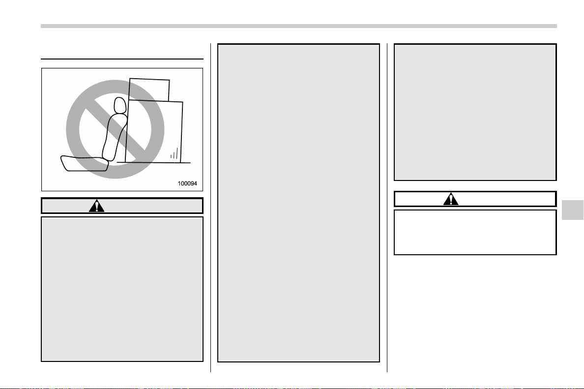
(451,1)
北米Model "A1700BE-B" EDITED: 2017/ 10/ 11
Loading your vehicle
WARNING
. Never allow passengers to ride
on a folded rear seatback or in the
trunk. Doing so may result in
serious injury.
. Never stack luggage or other
cargo higher than the top of the
seatback because it could tumble
forward and injure passengers in
the event of a sudden stop or
accident. Keep luggage or cargo
low, as close to the floor as
possible.
. Stow cargo and luggage in the
trunk whenever possible.
. To prevent cargo and luggage
from sliding forward during brak-
ing, do not stack anything in the
enlarged trunk. Keep cargo and
luggage low, as close to the floor
as possible.
. When you carry something inside
the vehicle, secure it whenever
you can to prevent it from being
thrown around inside the vehicle
during sudden stops, sharp turns
or in an accident.
. Do not pile heavy loads on the
roof. These loads raise the vehi-
cle’s center of gravity and make it
more prone to tip over.
. Secure lengthy items properly to
prevent them from shooting for-
ward and causing serious injury
during a sudden stop.
. Never exceed the maximum load
limit. If you do, some parts on
your vehicle can break, or it can
change the way your vehi cle
handles. This could result in loss
of control and cause personal
injury. Also, overloading can
shorten the life of your vehicle.
. Do not place cargo or luggage in
or on the following locations as
the i tem may g et under the
clutch, brake, or accelerator ped-
al and prevent the pedals from
being depressed properly, block
the driver ’s vision, or hit the
driver or pass engers, causing
an accident:
– At the feet of the driver
– On the front passenger or rear
seats (when stacking items)
– On the rear shelf
– On the instrument panel
– On the dashboard
CAUTION
Do not carry spray cans, containers
with flammable or corrosive liquids
or any other dangerous items inside
the vehicle.
NOTE
For better fuel economy, do not carry
unneeded cargo.
– CONTINUED –
Driving tips/Loading your vehicle
8-11
8
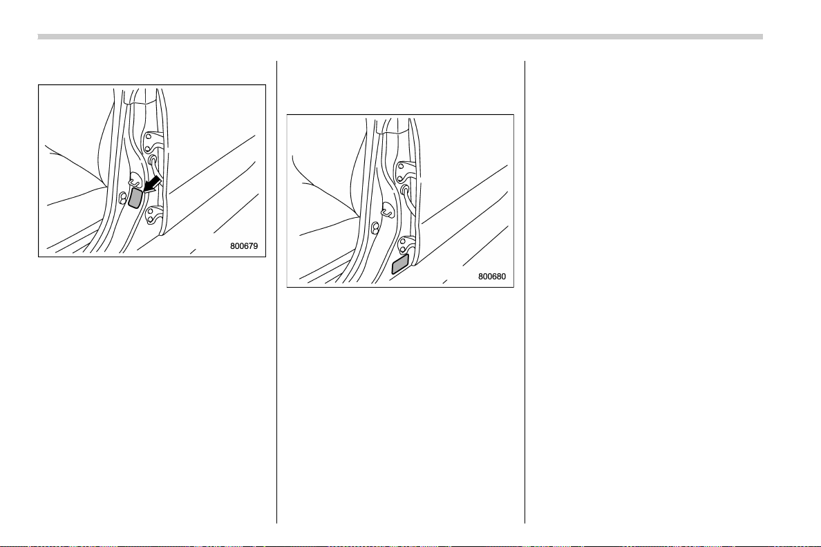
(452,1)
北米Model "A1700BE-B" EDITED: 2017/ 10/ 11
& Vehicle capacity weight
Vehicle placard
The load capacity of your vehicle is
determined by weight, not by available
cargo space. The maximum load you can
carry in your vehicle is shown on the
vehicle placard attached to the driver’s
side door pillar. It includes the total weight
of the driver and all passengers and their
belongings, any optional equipment such
as a roof rack or bike carrier, etc.
& GVWR and GAWR (Gross Ve-
hicle Weight Rating and
Gross Axle Weight Rating)
Certification label
The certification label attached to the
driver ’s side doorjamb shows GVWR
(Gross Vehicle Weight Rating) and GAWR
(Gross Axle Weight Rating).
The GVW (Gross Vehicle Weight) must
never exceed the GVWR. GVW is the
combined total of weight of the vehicle,
fuel, driver, all passengers, luggage, and
any optional equipment. Therefore, the
GVW changes depending on the situation.
The GVWR equals Curb Weight (actual
weight of your vehicle – including standard
equipment, fluids, emergency tools and
spare tire assembly) plus the vehicle
capacity weight.
In addition, the total weight applied to each
axle (GAW) must never exceed the
GAWR. The front and rear GAWs can be
adjusted by relocating luggage inside the
vehicle.
Even if the total weight of your luggage is
lower than the vehicle capacity weight,
either front or rear GAW may exceed the
GAWR, depending on the distribution of
the luggage.
When possible, the load should be evenly
distributed throughout the vehicle.
If you carry heavy loads in the vehicle, you
should confirm that GVW and front and
rear GAWs are within the GVWR and
GAWR by putting your vehicle on a vehicle
scale, found at a commercial weighing
station.
Do not use replacement tires with a lower
load range than the originals because they
may lower the GVWR and GAWR limita-
tions. Replacement tires with a higher load
range than the originals do not increase
the GVWR and GAWR limitations.
Driving tips/Loading your vehicle
8-12
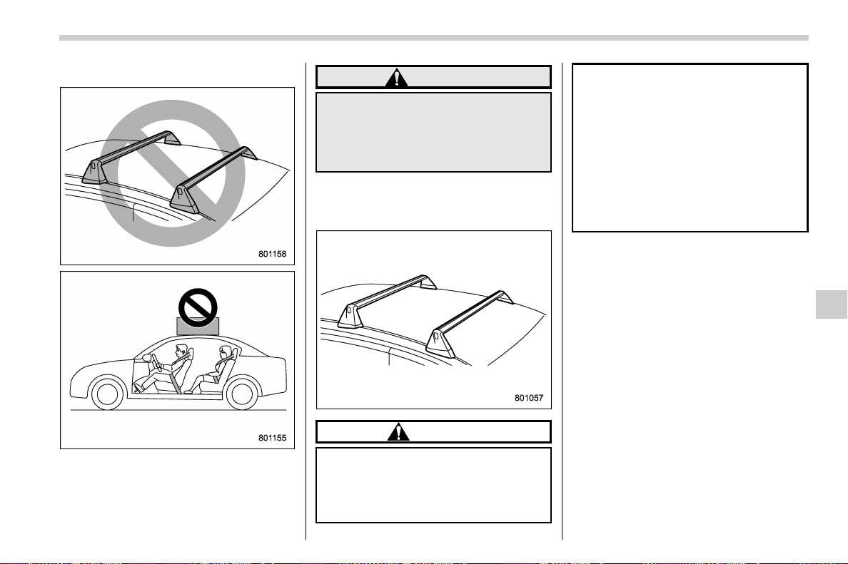
(453,1)
北米Model "A1700BE-B" EDITED: 2017/ 10/ 11
& Precautions for TYPE RA
The roof carri er and other equipment
cannot be attached on the carbon roof
because of the design.
WARNING
Do not place a roof carrier or any
other equipment on the roof of the
vehicle. Due to the design of the
roof, the cargo may fall off and cause
an accident.
& Roof molding and crossbar (if
equipped)
CAUTION
. For cargo carrying purposes, the
roof molding must be used to-
gether with a roof crossbar kit
and the appropriate carrying at-
tachment. Otherwise, damage to
the roof or paint or a dangerous
road hazard due to loss of cargo
could result.
. When using the roof crossbar kit,
make sure that the total weight of
the crossbars, carrying attach-
ment and cargo does not exceed
the maximum load limit. Over-
loading may cause damage to
the vehicle and create a safety
hazard.
Cargo can be carried after securing the
roof crossbar kit to the roof molding and
installing the appropriate carrying attach-
ment. When installing the roof crossbar kit,
follow the manufacturer’s instructions.
When carrying cargo on the roof using the
roof crossbar kit and carrying attachments,
never exceed the maximum load limit as
explained below. You should also be
careful that the vehicle does not exceed
the Gross Vehicle Weight Rating (GVWR)
and front and rear Gross Axle Weight
Rating (GAWR). For information about
loading cargo into or onto your vehicle,
refer to “Loading your vehicle” F8-11. The
maximum total load on the roof (including
crossbars, carrying attachments and car-
go) must not exceed 88 lbs (40 kg). Refer
to the crossbar installation instructions for
the maximum crossbar capacity. Place the
– CONTINUED –
Driving tips/Loading your vehicle
8-13
8
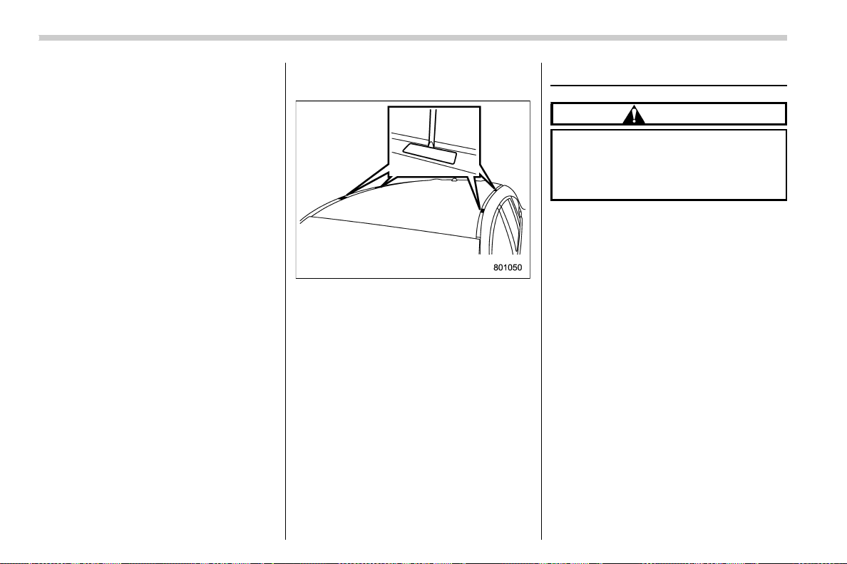
(454,1)
北米Model "A1700BE-B" EDITED: 2017/ 10/ 11
heaviest load at the bottom, close to the
roof, and evenly distribut e the cargo.
Always properly secure all cargo.
! Installing carrying attachments on
the crossbars
When installing any carrying attachments
such as the load carriers, crossbars, bike
carrier, ski carrier, kayak carrier, cargo
basket, etc., fol low the manufacturer’s
instructions of the load capacity and make
sure that the attachments are securely
installed. Use only attachments designed
specifically for the crossbars. Before oper-
ating the vehicle, make sure that the cargo
is properly secured on the attachment.
NOTE
Remember that the vehicle’s center of
gravity is altered with the weight of the
load on the roof, thus affecting the
driving characteristics.
Drive carefully. Avoid rapid starts, hard
cornering and abrupt stops. Crosswind
effects will be increased.
! Removal and installation of the
crossbars
Each of the two roof moldings has two
mounting poin ts for crossba rs. Each
mounting point is fitted with a cover. Use
a screwdriver to remove the covers. When
installing the crossbars on the roof mold-
ing, follow the manufacturer’s instructions.
Trailer towing
CAUTION
Your vehicle is neither designed nor
intended to be used for trailer tow-
ing. Therefore, never tow a trailer
with your vehicle.
SUBARU assumes no responsibility for
injuries or vehicle damage that may result
from trailer towing, from any trailer towing
equipment or from any errors or omissions
in the instructions accompanying such
equipment. SUBARU warranties do not
apply to vehicle damage or malfunction
caused by trailer towing.
Driving tips/Trailer towing
8-14
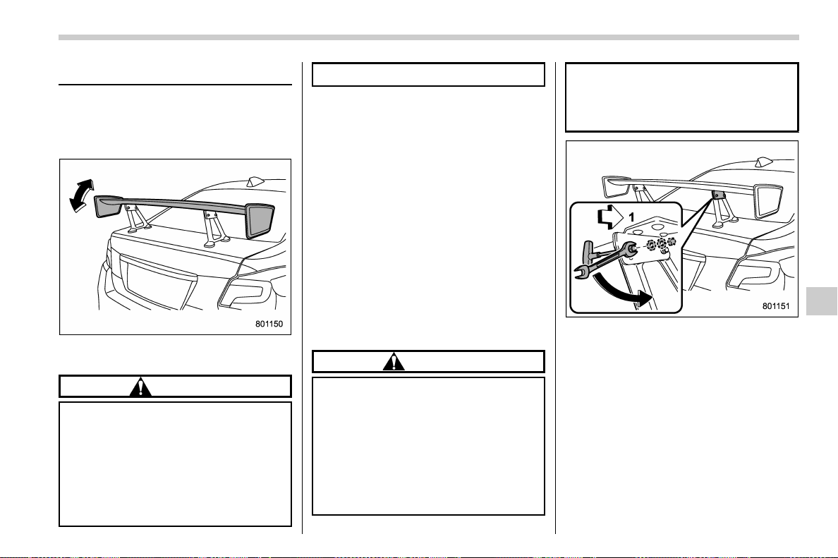
(455,1)
北米Model "A1700BE-B" EDITED: 2017/ 10/ 11
Rear wing (TYPE RA)
On initial delivery, the rear wing is adjusted
to an angle at which both stability at high
speed and enhanced handling can be
attained.
The rear wing can be adjusted to two
different angles.
CAUTION
When handling the rear wing, ob-
serve the following precautions.
. Do not push or pull the rear wing
with excessive force. Doing so
may damage the rear wing.
. When waxing the vehicle, be
careful not to leave any residual
wax between the wing and wing
end-plates.
& Adjusting the angle of the
rear wing
! Before adjusting the angle
. Stop the vehicle in a safe place on a
hard, flat surface.
. Apply the parking brake.
. Shift the shift lever to the “N” position.
. Stop the engine.
! Necessary tools
. TORX
®
wrench (T30)
. Wrench, socket wrench and socket, or
a similar tool (diameter 0.4 in (10 mm))
. Torque wrench
! Adjusting procedure
CAUTION
Observe the following precautions.
Otherwise, the rear wing may be
damaged.
. Make sure to loosen the rear nuts
and bolts before adjusting the
angle.
. When installing the rear bolts,
make sure that both the left and
right bolts are installed to the
same p osition for the desired
angle.
. Do not loosen the nuts and bolts
on the front side.
1) Front of vehicle
1. While holding the bolt on the rear side
with a TORX
®
wrench, use a wrench,
socket wrench and socket, or a similar tool
to remove the nut and washers.
– CONTINUED –
Driving tips/Rear wing (TYPE RA)
8-15
8
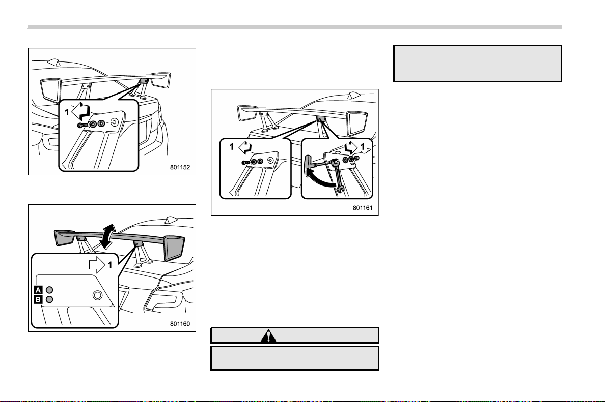
(456,1)
北米Model "A1700BE-B" EDITED: 2017/ 10/ 11
1) Front of vehicle
2. Remove the bolt and washers.
1) Front of vehicle
A) Standard position
B) High downforce position
3. Adjust the angle of the rear wing. We
recommend that you adjust the angle to
the standard position for attaining both
stability at high speed and enhanced
handling.
1) Front of vehicle
4. Install the bolt and washers. While
holding the bolt with a TORX
®
wrench,
use a wrench, socket wrench or a similar
tool to install the washers and nut and to
tighten the nut.
Tightening torque:
2.2 lbf·ft (3.0 N·m, 0.31 kgf·m)
! After adjusting the angle
WARNING
Make sure that the bolts and nuts are
tightened securely. If they are not
tightened securely, the rear wing
may come off while driving, possibly
leading to an accident.
& CFRP (Carbon Fiber Rein-
forced Plastic) parts
Due to the properties of the carbon fiber
used in CFRP parts, the shade and density
of the carbon fiber weave may vary.
Driving tips/Rear wing (TYPE RA)
8-16

(459,1)
北米Model "A1700BE-B" EDITED: 2017/ 10/ 11
If you park your vehicle in case of an
emergency ............................................................ 9-2
Temporary spare tire (if equipped) ........................ 9-2
Maintenance tools................................................... 9-3
Models with flat tire repair kit................................. 9-4
Models without flat tire repair kit ............................ 9-4
Flat tires................................................................... 9-5
Changing a flat tire ................................................ 9-5
Sealing flat tire (models with flat tire repair kit) ...... 9-8
Tire pressure monitoring system (TPMS)
(U.S.-spec. models) .............................................9-17
Jump starting ........................................................ 9-18
How to jump start .................................................9-18
Engine overheating............................................... 9-20
If steam is coming from the engine
compartment ......................................................9-20
If no steam is coming from the engine
compartment ......................................................9-20
Towing ................................................................... 9-21
Towing and tie-down hooks/holes ......................... 9-21
Using a flat-bed truck ...........................................9-24
Towing with all wheels on the ground ...................9-25
Electronic parking brake – if the electronic
parking brake cannot be released (models
with electronic parking brake system) ............ 9-25
Access key fob – if access key fob does not
operate properly ................................................ 9-26
Locking and unlocking ......................................... 9-26
Switching power status ........................................9-26
Starting engine ..................................................... 9-27
Moonroof (if equipped) – if the moonroof
does not close ................................................... 9-28
If your vehicle is involved in an accident........... 9-28
In case of emergency
9
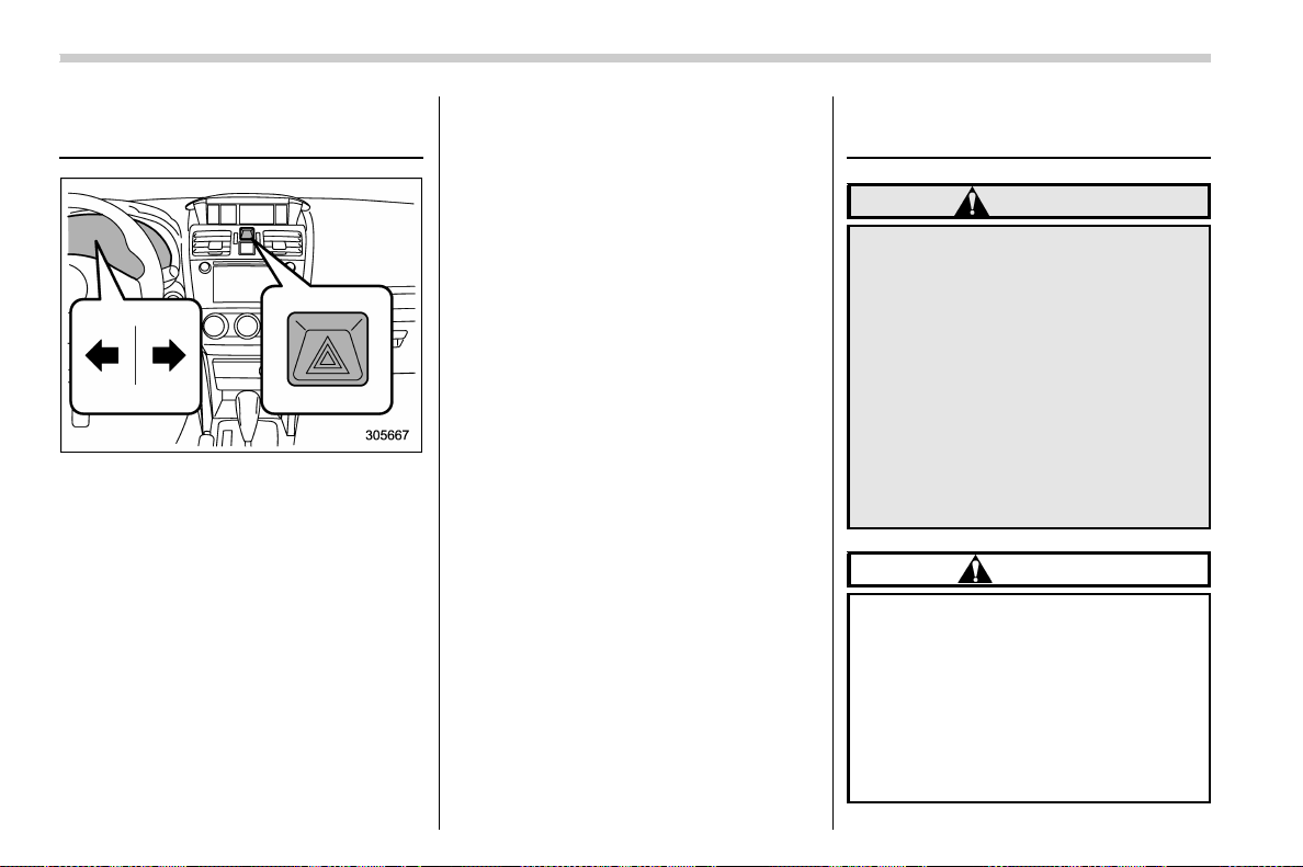
(460,1)
北米Model "A1700BE-B" EDITED: 2017/ 10/ 11
If you park your vehicle in
case of an emergency
Use the hazard warning flasher in day or
night to warn other drivers when you have
to park your veh icle under emergency
conditions.
Avoid stopping on the road. It is best to
safely pull off the road if a problem occurs.
You can activate the hazard warning
flasher regardless of the ignition switch
position.
Turn on the hazard warning by pushing the
hazard warning flasher switch. Turn it off
by pushing the switch again.
NOTE
When the hazard warning flasher is on,
the turn signals do not work.
Temporary spare tire (if
equipped)
WARNING
When a spare tire is mounted or a
wheel rim is replaced without the
original pressure sensor/transmitter
being transferred, the low tire pres-
sure warning light will illuminate
steadily after blinking for approxi-
mately one minute. This indicates
the tire pressure monitoring system
(TPMS) is unable to monitor all four
road wheels. Contact your SUBARU
dealer as soon as possible for tire
and sensor replacement and/or sys-
tem resetting.
CAUTION
. Never use any temporary spare
tire other than the original. Using
other sizes may result in severe
mechanical damage to the drive
train of your vehicle.
. Always conform to the following
instructions when using the tem-
porary spare tire. Otherwise, a
seriously dangerous situation
In case of emergency/If you park your vehicle in case of an emergency
9-2
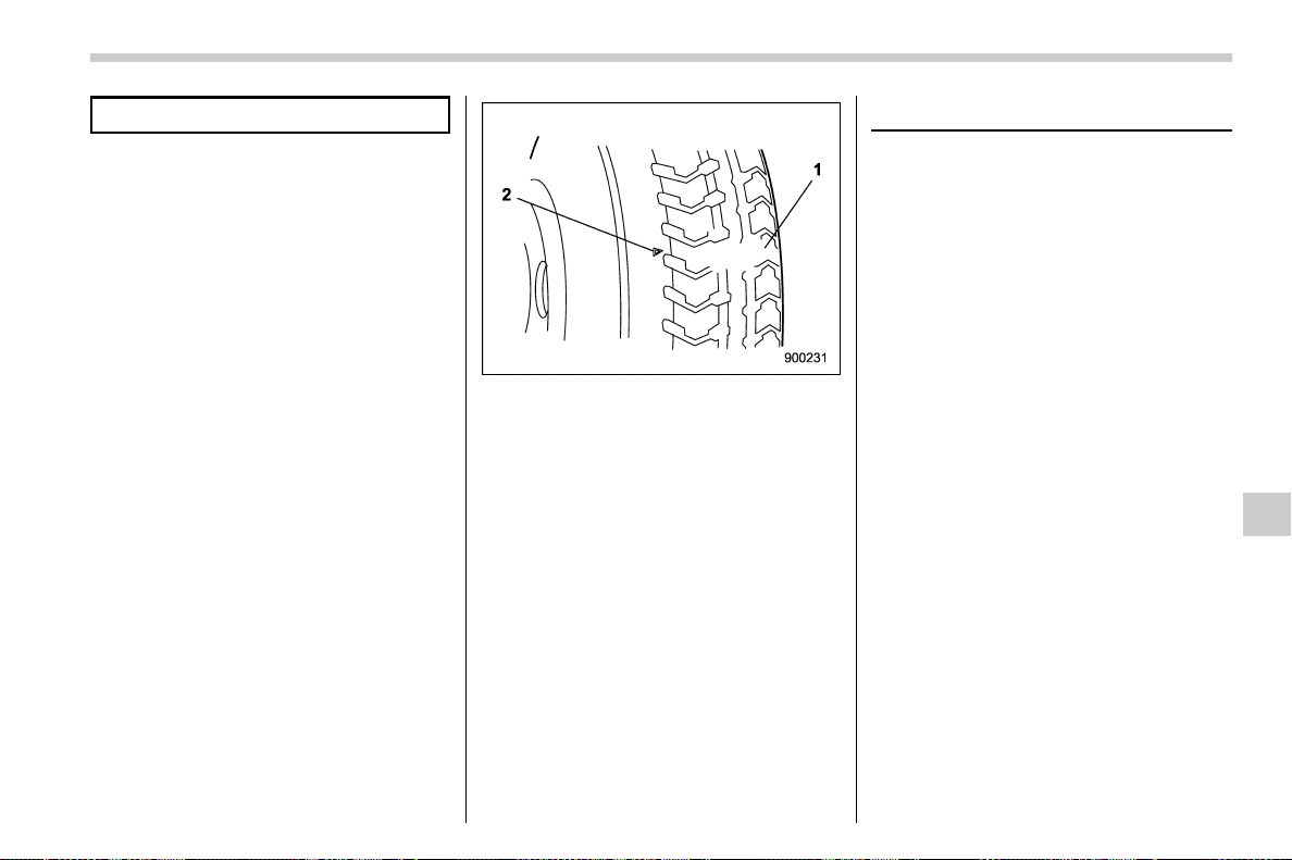
(461,1)
北米Model "A1700BE-B" EDITED: 2017/ 10/ 11
may occur.
The temporary spare tire is smaller and
lighter than a conventional tire and is
designed for emergency use only. Re-
move the temporary spare tire and re-
install the conventional tire as soon as
possible because the spare tire is de-
signed only for temporary use.
Check the inflation pressure of the tem-
porary spare tire periodically to keep the
tire ready for use. For the correct tire
pressure, refer to “Temporary spare tires”
F12-9.
When using the temporary spare tire, note
the following.
. Drive with caution when temporary
spare tire is fitted. Avoid hard acceleration
and braking, or fast cornering, as control of
the vehicle may be lost.
. Do not exceed 50 mph (80 km/h).
. Do not put a tire chain on the temporary
spare tire. Because of the smaller tire size,
a tire chain will not fit properly.
. Do not use two or more temporary
spare tires at the same time.
. Do not drive over obstacles. This tire
has a smaller diameter, so road clearance
is reduced.
1) Tread wear indicator bar
2) Indicator location mark
. When the wear indicator appears on
the tread, replace the tire.
. The temporary spare tire must be used
only on a rear wheel. If a front wheel tire
gets punctured, replace the wheel with a
rear wheel and install the temporary spare
tire in place of the removed rear wheel.
. Always set the driver’s control center
differential to the manual mode and adjust
the initial LSD torque to the minimum.
Maintenance tools
Your vehicle is equipped with the following
maintenance tools.
. Jack
. Jack handle
. Screwdriver
. Towing hook (eye bolt)
. Wheel nut wrench
– CONTINUED –
In case of emergency/Maintenance tools
9-3
9
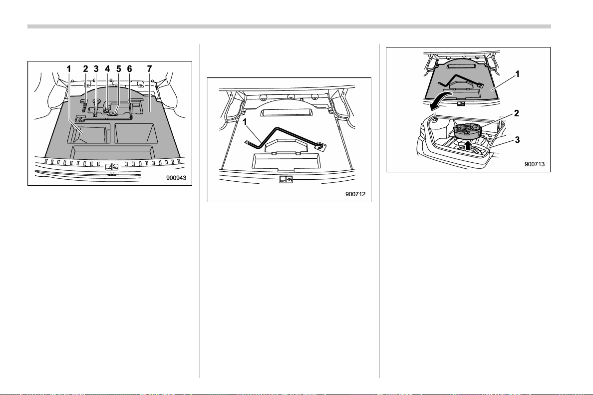
(462,1)
北米Model "A1700BE-B" EDITED: 2017/ 10/ 11
& Models with flat tire repair kit
1) Flat tire repair kit
2) Screwdriver
3) Towing hook (eye bolt)
4) Wheel nut wrench
5) Jack
6) Jack handle
7) Under-floor storage compartment (Refer
to “Under-floor storage compartment”
F6-12.)
& Models without flat tire repair
kit
1) Jack handle
1) Under-floor storage compartment (if
equipped) (Refer to “Under-floor storage
compartment” F6-12.)
2) Tool bucket
3) Spare tire
In case of emergency/Maintenance tools
9-4
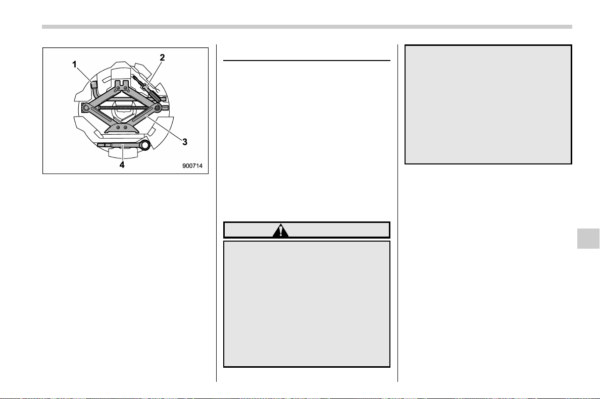
(463,1)
北米Model "A1700BE-B" EDITED: 2017/ 10/ 11
1) Wheel nut wrench
2) Screwdriver
3) Jack
4) Towing hook (eye bolt)
A jack handle is stored under the floor of
the trunk. A jack and a towing hook are
stored in the tool bucket that is located in
the recess of the spar e tire wheel. A
screwdriver and a wheel nut wrench are
stored in the vinyl bag. You can also store
these tools in the tool bucket.
NOTE
For how to use the jack, refer to “Flat
tires” F9-5.
Flat tires
If you have a flat tire while driving, never
brake suddenly; keep driving straight
ahead while gradually reducing speed.
Then slowly pull off the road to a safe
place.
& Changing a flat tire
! Models with flat tire repair kit
It may be difficult to change a flat tire.
However, it may be possible to seal the
tire. For details, refer to “Sealing flat tire
(models with flat tire repair kit)” F9-8.
! Models without flat tire repair kit
WARNING
. Do not jack up the vehicle on an
incline or a loose road surface.
The jack can come out of the
jacking point or sink into the
ground and this can result in a
severe accident.
. Use only the jack provided with
your vehicle. The jack supplied
with the vehicle is designed only
for changing a tire. Never get
under the vehicle while support-
ing the vehicle with this jack.
. Before using the jack, be sure
that there are no occupants or
cargo in the vehicle.
. Always turn off the engine before
raising the flat tire off the ground
using the jack. Never swing or
push the vehicle supported with
the jack. The jack can come out of
the jacking point due to a jolt and
this can result in a severe acci-
dent.
1. Park on a hard, level surface, when-
ever possible, then stop the engine.
2. Set the parking brake securely and
shift the shift lever in reverse (MT models)
or the select lever to the “P” (Park) position
(CVT models).
3. Turn on the hazard warning flasher and
have everyone get out of the vehicle.
– CONTINUED –
In case of emergency/Flat tires
9-5
9
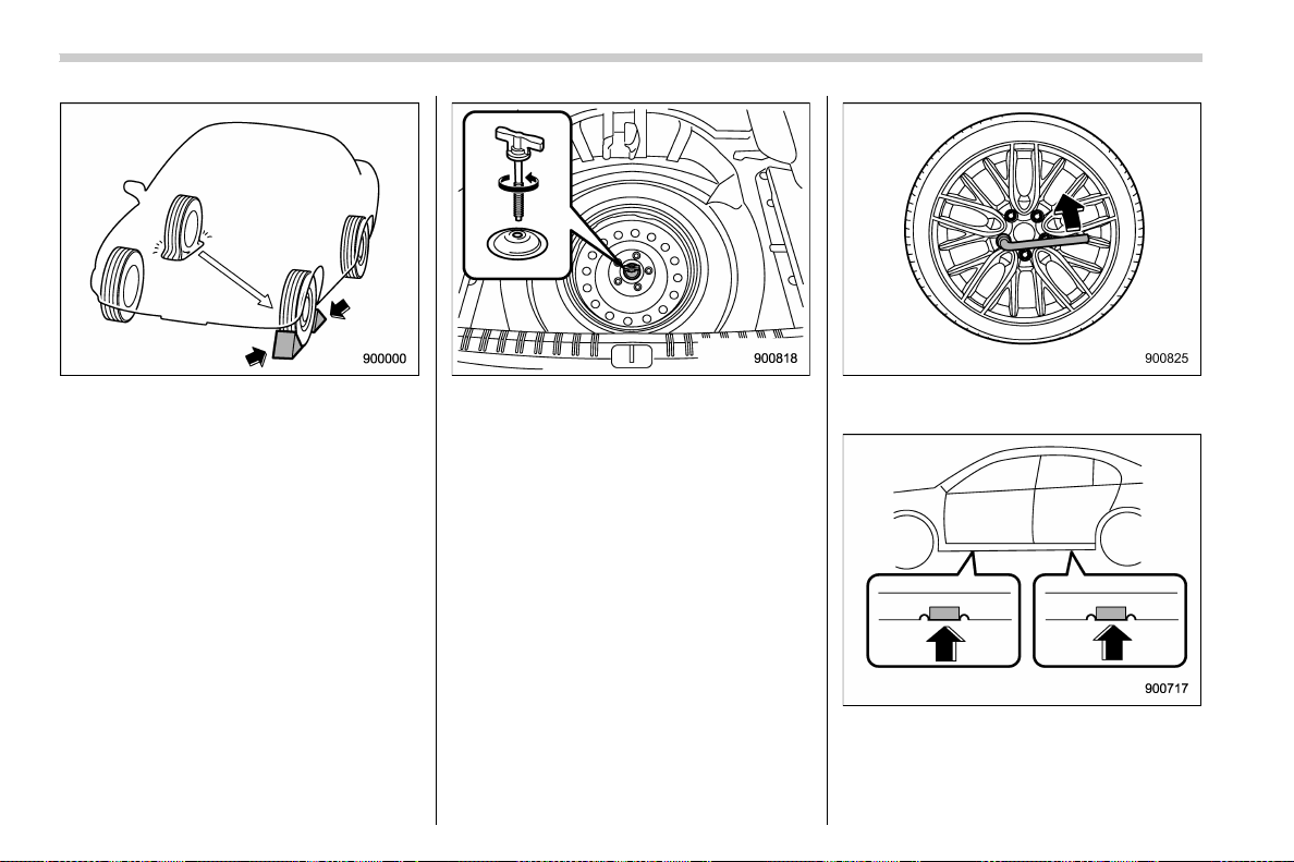
(464,1)
北米Model "A1700BE-B" EDITED: 2017/ 10/ 11
4. Put wheel blocks at the front and rear
of the tire diagonally opposite the flat tire.
5. Take out the jack, jack handle and
wheel nut wrench.
The tools and the spare tire are stored
under the floor of the trunk. R efer to
“Maintenance tools” F9-3.
NOTE
Make sure that the jack is well lubri-
cated before using it.
6. Take out the tool bucket and turn the
attaching bolt counterclockwise, then take
the spare tire out.
NOTE
If the spare tire provided in your vehicle
is a temporary spare tire, carefully read
“Temporary spare tire” F9-2 and
strictly follow the instructions.
7. Loosen the wheel nuts using the wheel
nut wrench but do not remove the nuts.
Jack-up points
8. Place the jack under the side sill at the
front or rear jack-up point closest to the flat
tire.
In case of emergency/Flat tires
9-6
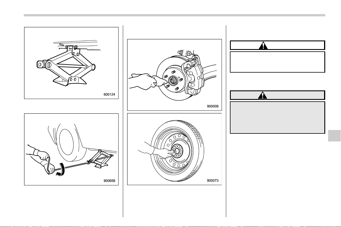
(465,1)
北米Model "A1700BE-B" EDITED: 2017/ 10/ 11
Turn the jackscrew by hand until the jack
head engages firmly into the jack-up point.
9. Insert the jack handle into the jack-
screw, and turn the handle until the tire
clears the ground. Do not raise the vehicle
higher than necessary.
10. Remove the wheel nuts and the flat
tire.
11. Before putting the spare tire on, per-
form the following steps.
. Clean the mounting surface of the
wheel and hub with a cloth.
. Clean the threaded parts with a cloth
and check the conditions there.
CAUTION
If the threaded part was damaged,
you should immediately contact
your SUBARU dealer.
12. Put on the spare tire. Replace the
wheel nuts. Tighten them by hand.
WARNING
Do not use oil or grease on the wheel
studs or nuts when the spare tire is
installed. This could cause the nuts
to become loose and lead to an
accident.
13. Turn the jack handle counterclockwise
to lower the vehicle.
– CONTINUED –
In case of emergency/Flat tires
9-7
9
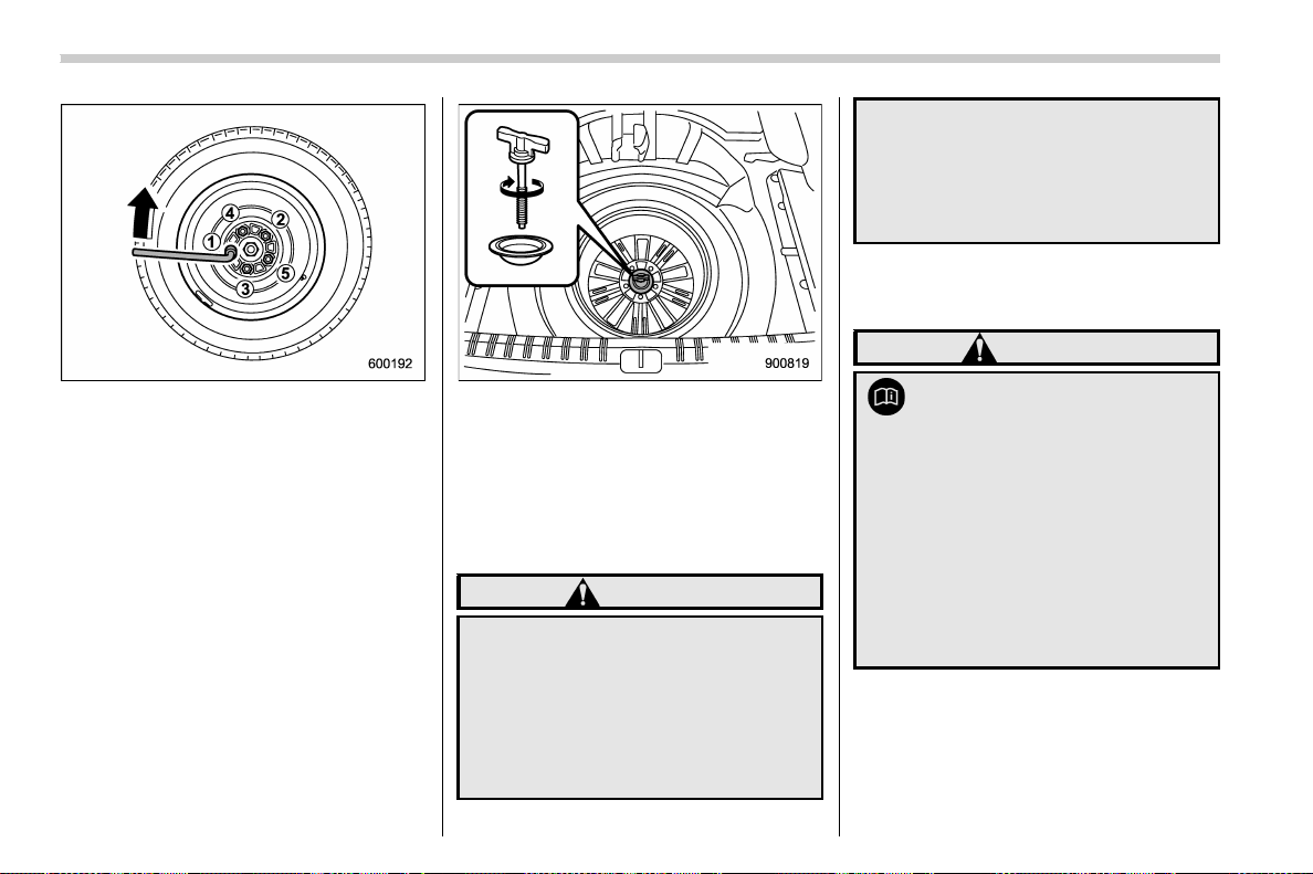
(466,1)
北米Model "A1700BE-B" EDITED: 2017/ 10/ 11
14. Use the wheel nut wrench to securely
tighten the wheel nuts to the specified
torque, following the tightening order in the
illustration.
For the wheel nut tightening torque, refer
to “Tires” F12-8. Never use your foot on
the wheel nut wrench or a pipe extension
on the wrench because you may exceed
the specified torque. Have the wheel nut
torque checked at the nearest automotive
service facility.
Except STI
15. Store the flat tire in the spare tire
compartment. For except STI models, put
in the spacer and tighten the attaching bolt
firmly.
Also store the jack, jack handle and wheel
nut wrench in their storage locations.
WARNING
. Never place a tire or tire changing
tools in the passenger compart-
ment after changing wheels. In a
sudden stop or collision, loose
equipment could strike occu-
pants and cause injury. Store
the tire and all tools in the proper
place.
. When you store a flat tire, be sure
to set the rear seatback to the
upright position. If you fold down
the seatback, an accident or
injury may occur when the flat
tire suddenly moves.
& Sealing flat tire (models with
flat tire repair kit)
WARNING
Read these instructions and
warnings carefully before sealing a
flat tire.
Compliance with these instructions
is vital to ensuring vehicle safety.
Noncompliance with these instruc-
tions means risking tire damage,
which can affect vehicle handling
and lead to loss of vehicle control.
This may result in serious injury or
death.
If the tire is punctured, you can seal the flat
tire temporarily by using the flat tire repair
kit. You can seal a flat tire caused, for
example, by nails or similar objects with
less than 0.2 in (4 mm). However, depend-
ing on the type and extent of tire damage,
In case of emergency/Flat tires
9-8
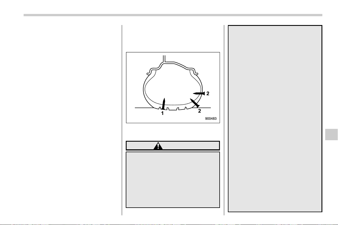
(467,1)
北米Model "A1700BE-B" EDITED: 2017/ 10/ 11
some tires can only be partially sealed or
not sealed at all, and this condition may
cause a loss of tire pressure. A loss of tire
pressure can affect vehicle handling,
leading to the loss of vehicle control.
After sealing the flat tire tempora rily,
change the tires with new ones as soon
as possible. We recommend that you have
the sealed tire changed by your nearest
SUBARU dealer. You may reuse the wheel
if the attached sealant is wiped off, but the
valve of the wheel must be replaced with a
new one. If you reuse the wheel without
replacing the valve, air may leak from the
valve.
For tire replacement, refer to “Tire replace-
ment” F11-36.
! Safety precautions when sealing flat
tire
Observe the following rules when sealing a
flat tire.
1) Sealing is possible
2) Sealing is not possible
WARNING
. Do not use the flat tire repair kit in
the following cases.
– The tire has already been
damaged as a result of being
driven in the under inflated
condition.
– The tire damage is not located
within the visible tread of the
tire.
– The tire damage is on the
sidewall of the tire.
– When the tire has been taken
off of the wheel.
– The wheel or the tire valve of
the flat tire is damaged.
– Two or more tires have been
punctured.
– The expiration date of the
sealant has passed.
– The tire is punctured by
pointed items such as nails
of 0.2 in (4 mm) or larger.
. When inflating the flat tire, if the
tire inflation pressure does not
reach the green zo ne of the
pressure gauge within 10 min-
utes, do not continue to seal the
tire. We recommend that you
contact your SUBARU dealer.
. Drive w ith caution and avoid
making sudden steering or driv-
ing maneuvers.
. Do not exceed a maximum speed
of 50 mph (80 km/h).
. Do not exceed a maximum driv-
ing distance of 125 miles (200
km).
. Do not use tire chains on a sealed
tire.
– CONTINUED –
In case of emergency/Flat tires
9-9
9
(468,1)
北米Model "A1700BE-B" EDITED: 2017/ 10/ 11
. Do not tow a trailer.
. If used for a purpose other than
sealing a flat tire, the flat tire
repair kit may cause a severe
accident or injury due to the fact
that compressed air can act as an
explosive or propellant.
. Safely park your vehicle on the
roadside so that you do not
obstruct the flow of traffic and
so that you are able to seal the flat
tire without being in danger.
. Apply the parking brake, even if
the vehicle is parked on a level
road, to make sure that the vehi-
cle will not move.
. Stop the engine before sealing
the flat tire.
. Tu rn on the hazard warning
flasher while sealing the flat tire.
. Do not attempt to remove foreign
objects like nails or screws that
have penetrated the tire. Leave
them as they are.
. Never leave the flat tire repair kit
unattended while in use.
. Only one tire can be repaired with
one bottle of sealant.
. The tires can be repaired when
the ambient temperature is −228F
(−308C) or higher.
CAUTION
. Remember that the flat tire repair
kit only provides temporary mo-
bility. Regulations concerning
tire repair after usage of flat tire
repair kit may differ from country
to country. We recommend that
you consult your SUBARU dealer
or tire dealer for advice.
. Store the flat tire repair kit safely
and secure it in the cargo area.
Storing it anywhere in the pas-
senger compartment is not advi-
sable because it could strike an
occupant in the event of a sudden
stop or collision and cause injury.
. Use the flat tire repair kit with
original vehicle tires only.
. Do not keep the air compressor
operating for more than 10 min-
utes, otherwise there is a risk of
overheating.
. The temperature of the air com-
pressor may become high. Be
careful not to burn yourself.
. When raining, take measures to
prevent the air compressor from
being exposed directly to the
rain. Exposing to rain may cause
a malfunction.
. Do not use air compressors other
than the one in the repair kit.
Using an air compressor other
than the one in the repair kit may
damage the tires.
. Do not disassemble or modify the
air compressor to enable the use
of a power supply or a battery
other than DC12V.
. If a temporary puncture repair is
performed with the repair kit, the
Tire Pressure Monitoring System
(TPMS) may not operate nor-
mally.
In case of emergency/Flat tires
9-10
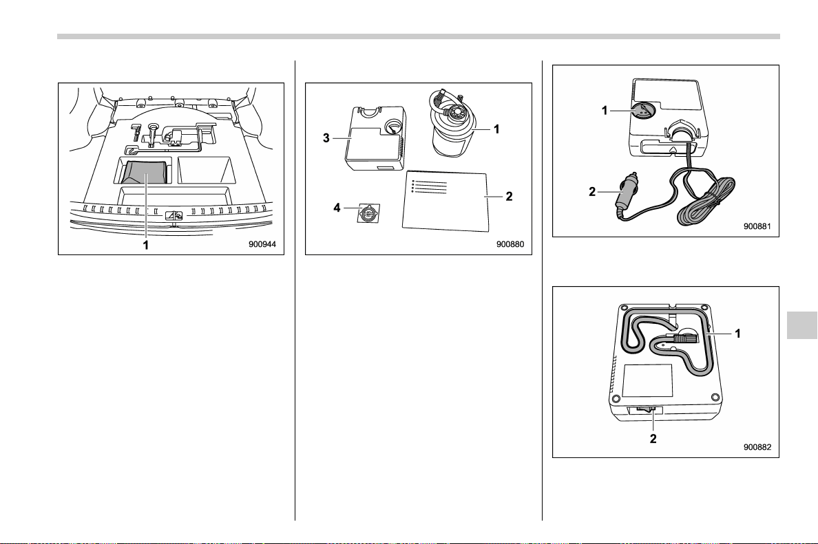
(469,1)
北米Model "A1700BE-B" EDITED: 2017/ 10/ 11
! Location of the flat tire repair kit
1) Flat tire repair kit
The flat tire repair kit is stored under the
floor of the cargo area.
! Contents of the flat tire repair kit
1) Sealant bottle
2) Quick reference guide
3) Air compressor
4) Speed limit label
The above repair kits are packed in a black
bag. Return them to the black bag after
use.
Air compressor (front side)
1) Air gauge
2) Power plug
Air compressor (rear side)
1) Hose
2) Compressor switch
– CONTINUED –
In case of emergency/Flat tires
9-11
9
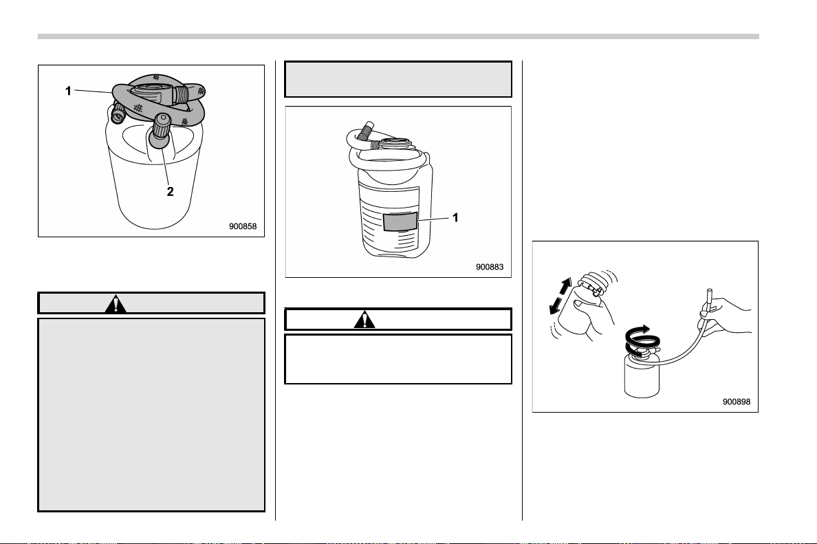
(470,1)
北米Model "A1700BE-B" EDITED: 2017/ 10/ 11
Sealant bottle
1) Hose
2) Valve
WARNING
. Do not drink the sealant. If the
sealant is accidentally swal-
lowed, seek medical attention
immediately.
. If the sealant splashes onto your
skin or eyes, wash it away im-
mediately with plenty of water. If
necessary, seek medical atten-
tion immediately.
. Keep the flat tire repair kit out of
the reach of children.
. If a person who is al lergic to
natural rubber comes in contact
with the sealant, allergy symp-
toms may occur.
1) Expiration date
CAUTION
Replace the sealant bottle with a
new one before the expiration date
passes.
! How to seal the flat tire
To seal the flat tire, perform the following
steps.
. First, pump in the sealant and air. Drive
the vehicle for approximately 10 minutes
or 3 miles (5 km) so that the sealant can
seal the damaged area.
. Stop the vehicle again, check and, if
necessary, adjust the pressure of the
damaged tire.
. After that, you can continue to drive
carefully no faster than 50 mph (80 km/h)
and within the maximum distance of 125
miles (200 km).
Inform all other users of the vehicle that the
tire has been temporarily sealed with the
flat tire repair kit and make them aware of
the special driving conditions to be ob-
served.
1. Shake the sealant bottle well. Loosen
the hose.
In case of emergency/Flat tires
9-12
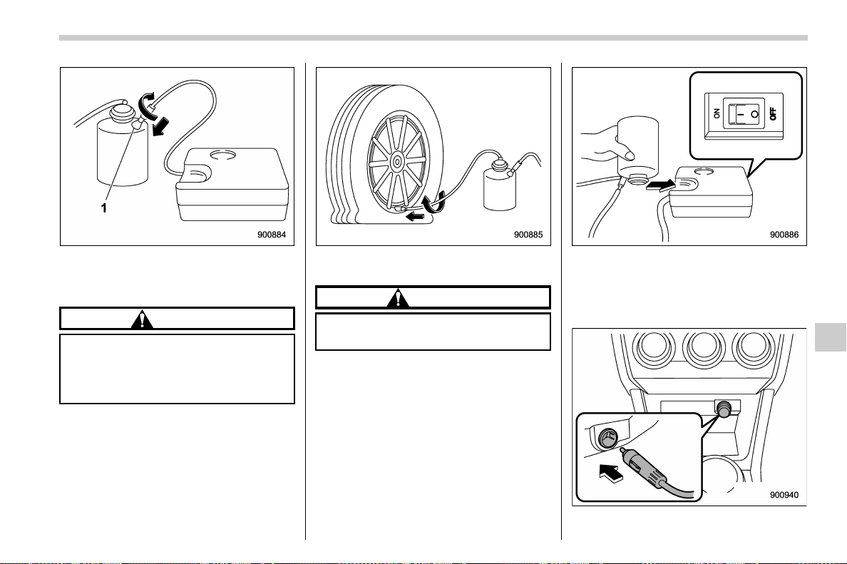
(471,1)
北米Model "A1700BE-B" EDITED: 2017/ 10/ 11
1) Valve
2. Connect the air compressor hose to
the valve on the bottle.
CAUTION
. Make sure that the air compres-
sor switch is OFF.
. The sealant may leak if the fitting
is not tight enough.
Connect the hose from the bottle to the tire
valve stem tightly.
CAUTION
The sealant may leak if the fitting is
not tight enough.
3. Turn the bottle upside down and tilt the
bottle cap into the bottle holder of the air
compressor.
Make sure that the air compressor switch
is OFF.
4. Connect the power plug of the air
– CONTINUED –
In case of emergency/Flat tires
9-13
9
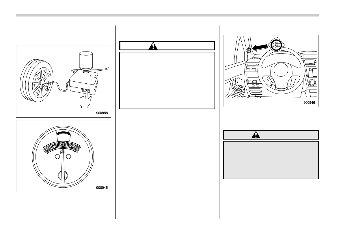
(472,1)
北米Model "A1700BE-B" EDITED: 2017/ 10/ 11
compressor into the accessory power
outlet. Apply the parking brake and turn
on the ignition switch to the “ACC” position.
Apply the parking brake and turn on the
ignition switch to the “ACC ” position. Turn
the air compressor switch on and adjust
the air pressure to the appropriate level
(green zone of the air gauge).
CAUTION
. Do not run the air compressor for
more than 10 minutes as it can
get hot. Be careful not to get
burned.
. If tire pressure doesn’t reach the
green zone for 10 minutes, this kit
will be unable to seal the tire.
Please contact your SUBARU
dealer for help.
NOTE
. After the compressor starts to oper-
ate, the air pressure will temporarily
rise to 45 psi (300 kPa, 3.0 kgf/cm
2
)or
higher. After about 30 seconds when all
of the sealant is inside the tire, the air
pressure will lower, representing the air
pressure in the tire.
. In extremely low temperatures −228F
to −48F(−308Cto−208C), the viscosity
of the sealant increases and the sealant
will flow more slowly. In such tempera-
tures, bring the sealant into the vehicle
to warm it up before use.
. When mending the tire, if the air
pressure gauge is hard to read, turn the
compressor switch off once to get an
accurate reading.
5. While filling the tire with air, attach the
speed limit label on the position shown in
the illustration.
WARNING
Do not attach the speed limit label in
a position where the label hides the
warning lamp or o n the steering
wheel. It may interfere with the
normal operation of the airbag and
lead to a critical failure.
In case of emergency/Flat tires
9-14
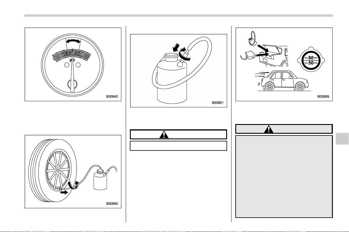
(473,1)
北米Model "A1700BE-B" EDITED: 2017/ 10/ 11
6. Turn the air compressor power switch
off when the air pressure reaches the
green zone of the air gauge.
Remove the power plug from the acces-
sory power socket.
Remove the hose after filling the tire with
air and fasten the valve cap.
Connect the hose of the bottle to the valve
of the bottle in a circular fashion to avoid
leakage of the remaining sealant.
CAUTION
The sealant may stain clothing.
7. Stow the kit back in the vehicle and
drive your vehicle immediately for 10
minutes or 3 miles (5 km).
WARNING
. Drive carefully. Do not exceed 50
mph (80 km/h). Driving faster
than that can result in the vehicle
shaking.
. Do not use tire chains on a sealed
tire.
. Do not tow a trailer.
. If heavy vibrations, unsteady
steering behavior or noises oc-
cur while driving, reduce your
speed and drive with caution to
a location where it is safe for you
to stop the vehicle. Recheck the
– CONTINUED –
In case of emergency/Flat tires
9-15
9
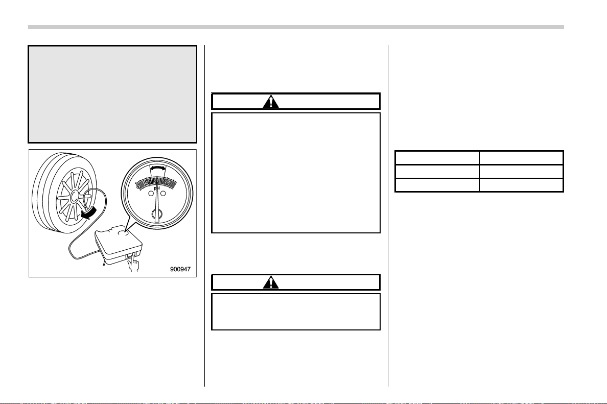
(474,1)
北米Model "A1700BE-B" EDITED: 2017/ 10/ 11
tire and its pressure. If the tire
pressure is in the red zone of the
air gauge or if there are any
cracks, bumps or similar tire
damage visible, temporary re-
pairs cannot be performed with
the repair kit. We recommend that
you consult with your SUBARU
dealer or road service provider.
8. After driving for 10 minutes or 3 miles
(5 km), whichever comes first, stop the
vehicle in a safe place to recheck the air
pressure (see step 4).
If necessary, fill the tire with air to the
appropriate air pressure again and drive
carefully to the nearest SUBARU dealer
for tire, valve stem and sealant bottle
replacement.
NOTE
Connect the air compressor only to the
tire valve.
CAUTION
. If the air pressure is in red zone of
the air gaug e, the kit did not
successfully seal the puncture.
In this case, please stop driving
and contact your SUBARU dealer
for help.
. Do not drive your vehicle with the
sealed tire for more than 125
miles (200 km). Failure to replace
the valve stem may result in air
leakage at the valve stem.
Before the tire is removed from the rim,
inform your SUBARU dealer or other tire
dealer that the tire contains sealant.
CAUTION
The sealant bottle and speed limit
label need to be replaced after using
the flat tire repair kit.
NOTE
New sealant and replacement parts can
be purchased from your authorized
repair shop or SUBARU dealer, and
they should also be installed into the kit
by a specialist. Empty sealant bottles
and replacement parts must be re-
turned to your SUBARU dealer or
disposed of in compliance with local
waste disposal regulations.
! Technical data of air compressor
Line voltage DC 12V
Operating voltage DC 10 – 15V
Amperage
Max. 10A
In case of emergency/Flat tires
9-16
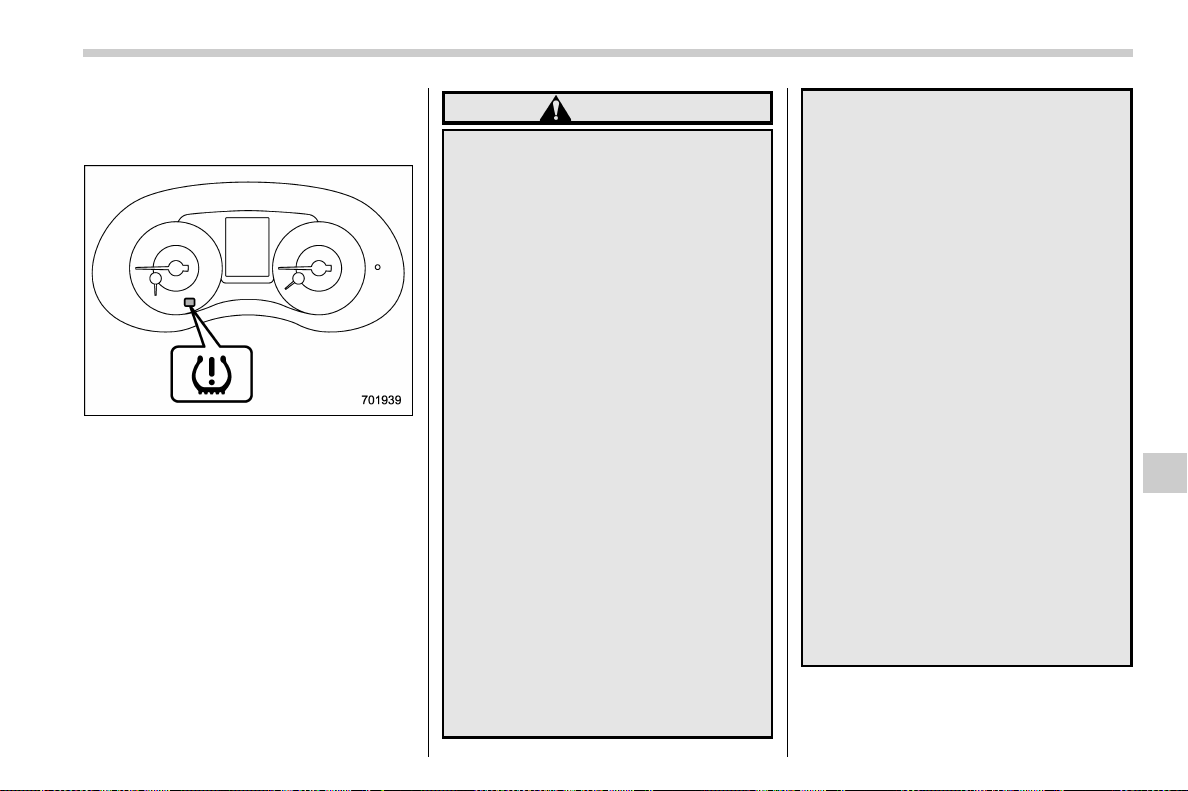
(475,1)
北米Model "A1700BE-B" EDITED: 2017/ 10/ 11
& Tire pressure monitoring
system (TPMS) (U.S.-spec.
models)
Low tire pressure warning light
The tire pressure monitoring system pro-
vides the driver with the warning message
indicated by sending a signal from a
sensor that is installed in each wheel when
tire pressure is severely low.
The tire pressure monitoring system will
activate only when the vehicle is driven.
Also, this system may not react immedi-
ately to a sudden drop in tire pressure (for
example, a blow-out caused by running
over a sharp object).
WARNING
. If the low tire pressure warning
light illuminat es while driv ing,
never brake suddenly. Instead,
perform the following procedure.
(1) Keep driving straight ahead
while gradually reducing
speed.
(2) Slowly pull off the road to a
safe place. Otherwise an acci-
dent involving serious vehicle
damage and serious personal
injury could occur.
(3) Check the pressure for all four
tires and adjust the pressure
to the COLD tire pressure
shown on the vehicle placard
on the door pillar on the
driver’s side.
If this light still illuminates while
drivi ng after adjusting the tire
pressure, a tire may have signifi-
cant damage and a fast leak that
causes the tire to lose air rapidly.
If you have a flat tire, refer to “Flat
tires” F9-5.
. When a spare tire is mounted or a
wheel rim is replaced without the
original pressure sensor/trans-
mitter being transferred, the low
tire pressure warning light will
illuminate steadily after blinking
for approximately one minute.
This indicates the TPMS is unable
to monitor all four road wheels.
Contact your SUBARU dealer as
soon as possible for tire and
sensor replacement and/or sys-
tem resetting.
. When a tire is repaired with liquid
sealant, the tire pressure warning
valve and transmitter may not
operate properly. If a liquid sea-
lant is used, contact your nearest
SUBARU dealer or other qualified
service shop as soon as possi-
ble. Make sure to replace the tire
pressure warning valve a nd
transmitter when replacing the
tire. You may reuse the wheel if
there is no damage to it and if the
sealant residue is properly
cleaned off.
If the light illuminates steadily
after blinking for approximately
one minute, promptly contact a
SUBARU dealer to have the sys-
tem inspected.
In case of emergency/Flat tires
9-17
9
(476,1)
北米Model "A1700BE-B" EDITED: 2017/ 10/ 11
Jump starting
WARNING
. Battery fluid is SULFURIC ACID.
Do not let it come in contact with
the eyes, skin, clothing or the
vehicle.
If battery fluid gets on you, thor-
oughly flush the exposed area
with water immediately. Get med-
ical help if the fluid has entered
your eyes.
If battery fluid is accidentally
swallowed, immediately drink a
large amount of milk or water,
and obtain immediate medical
help.
Keep everyone including chil-
dren away from the battery.
. The gas generated by a battery
explodes if a flame or spark is
brought near it. Do not smoke or
light a match while jump starting.
. Never attempt jump starting if the
discharged battery is frozen. It
could cause the battery to burst
or explode.
. Whenever working on or around a
battery, always wear suitable eye
protectors, and remove metal
objects such as rings, bands or
other metal jewelry.
. Be sure the jumper cables and
clamps on them do not have
loose or missing insulation.
Do not jump start unless cables
in suitable condition are avail-
able.
. A running engine can be danger-
ous. Keep your fingers, hands,
clothing, hair and tools away
from the cooling fan, belts and
any other moving engine parts.
Removing rings, watches and
ties is advisable.
. Jump starting is dangerous if it
done incorrectly. If you are un-
sure about the proper procedure
for jump starting, consult a com-
petent mechanic.
When your vehicle does not start due to a
run down (discharged) battery, the vehicle
may be jump started by connecting your
battery to another battery (called the
booster battery) with jumper cables.
& How to jump start
1. Make sure the booster battery is 12
volts and the negative terminal is
grounded.
2. If the booster battery is in another
vehicle, do not let the two vehicles touch.
3. Turn off all unnecessary lights and
accessories.
4. Connect the jumper cables exactly in
the sequence illustrated.
In case of emergency/Jump starting
9-18
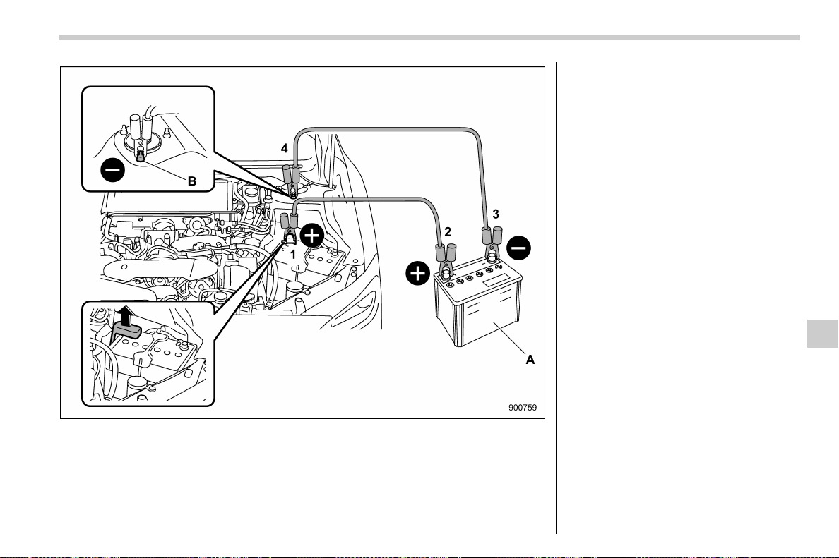
(477,1)
北米Model "A1700BE-B" EDITED: 2017/ 10/ 11
A) Booster battery
B) Strut mounting nut
(1) Connect one jumper cable to the
positive (+) terminal on the discharged
battery.
(2) Connect the other end of the
jumper cable to the positive (+) term-
inal of the booster battery.
(3) Connect one end of the other cable
to the negative (−) terminal of the
booster battery.
(4) Connect the other end of the cable
to the strut mounting nut of the vehicle
with the discharged battery.
Make sure that the cables are not near any
moving parts and that the cable clamps are
not in contact with any other metal.
5. Start the engine of the vehicle with the
booster battery and run it at moderate
speed. Then start the engine of the vehicle
that has the discharged battery.
6. When finished, carefully disconnect
the cables in exactly the reverse order.
In case of emergency/Jump starting
9-19
9
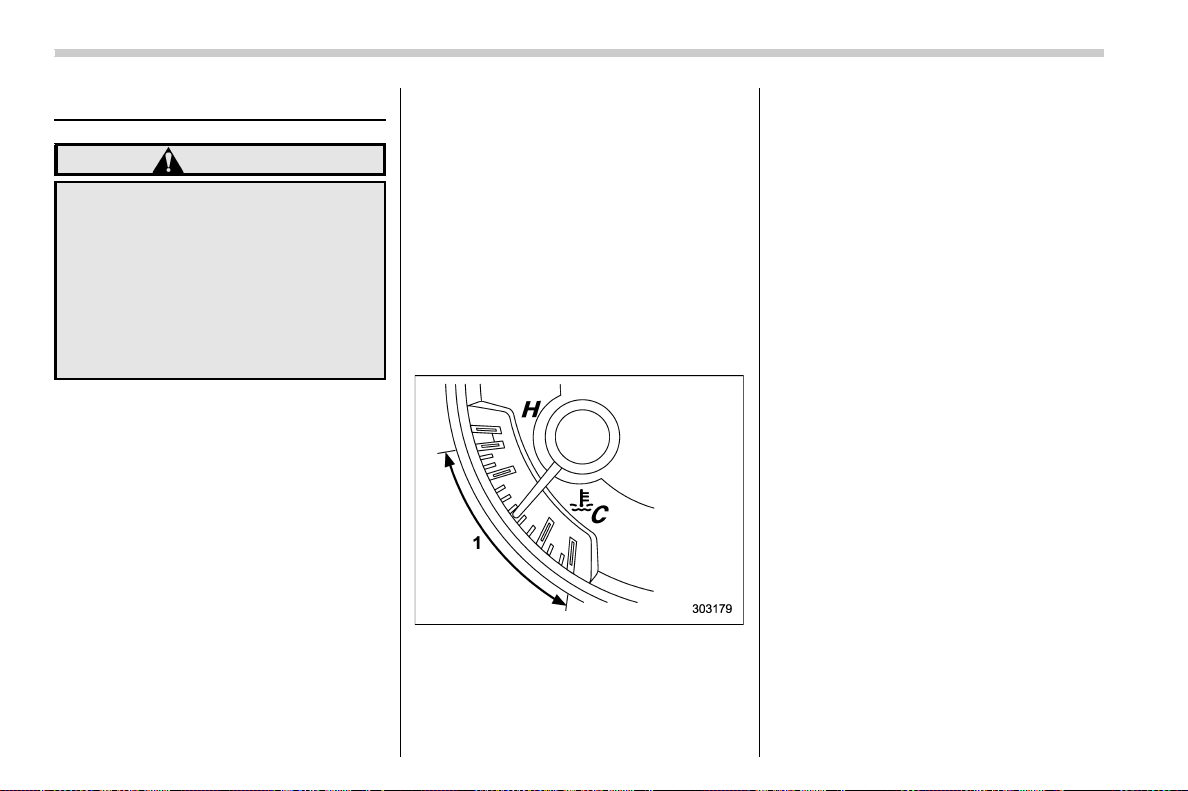
(478,1)
北米Model "A1700BE-B" EDITED: 2017/ 10/ 11
Engine overheating
WARNING
Never attempt to remove the radiator
cap until the engine has been shut
off and has fully cooled down. When
the engine is hot, the coolant is
under pressure. Removing the cap
while the engine is still hot could
release a spray of boiling hot cool-
ant, which could burn you very
seriously.
If the engine overheats, safely pull off the
road and stop the vehicle in a safe
location.
& If steam is coming from the
engine compartment
. Turn off the engine and get everyone
away from the vehicle until it cools down.
. Contact an authorized SUBARU deal-
er.
& If no steam is coming from the
engine compartment
1. Keep the e ngin e runni ng at idli ng
speed.
2. Open the engine hood to ventilate the
engine compartment. Refer to “Engine
hood” F11-9.
Confirm that the cooling fan is turning. If
the fan is not turning, immediately turn off
the engine and contact an authorized
SUBARU dealer for repair.
3. After the engine coolant temperature
has dropped, turn off the engine.
Temperature gauge
1) Normal operating range
If temperature gauge stays in the over-
heated zone, turn off the engine. Refer to
“Temperature gauge” F3-11.
4. After the engine has fully cooled down,
check the coolant level in the reserve tank.
If the coolant level is below the “LOW”
mark, add coolant up to the “FULL” mark.
NOTE
For details about how to check the
coolant level or how to add coolant,
refer to “Engine coolant” F11-17.
5. If there is no coolant in the reserve
tank, add coolant to the reserve tank. Then
remove the radiator cap and fill the radiator
with coolant.
If you remove the radiator cap from a hot
radiator, first wrap a thick cloth around the
radiator cap, then turn the cap counter-
clockwise slowly without pressing down
until it stops. Release the pressure from
the radiator. After the pressure has been
fully released, remove the cap by pressing
down and turning it.
In case of emergency/Engine overheating
9-20
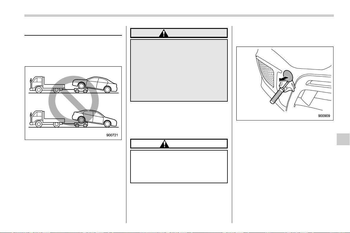
(479,1)
北米Model "A1700BE-B" EDITED: 2017/ 10/ 11
Towing
If towing is necessary, it is best done by
your SUBARU dealer or a commercial
towing service. Observe the following
procedures for safety.
WARNING
Never tow AWD models (both CVT
andMTmodels)withthefront
wheels raised off the ground while
the rear wheels are on the ground, or
with the rear wheels raised off the
ground while the front wheels are on
the ground. This will cause the
vehicle to spin away due to the
operation or deterioration of the
center differential.
& Towing and tie-down hooks/
holes
The towing hook should be used only in an
emergency.
CAUTION
Use only the specified towing hook
and tie-down hooks/holes. Never
use suspension parts or other parts
of the body for towing or tie-down
purposes.
Front towing hook:
1. Take the towing hook, screwdriver and
wheel nut wrench out of the tool bucket.
2. Cover the tip of a flat-head screwdriver
with vinyl tape or cloth so that it will not
scratch the bumper. Insert the flat-head
screwdriver into the cutout of the cover and
pry open the cover.
– CONTINUED –
In case of emergency/Towing
9-21
9
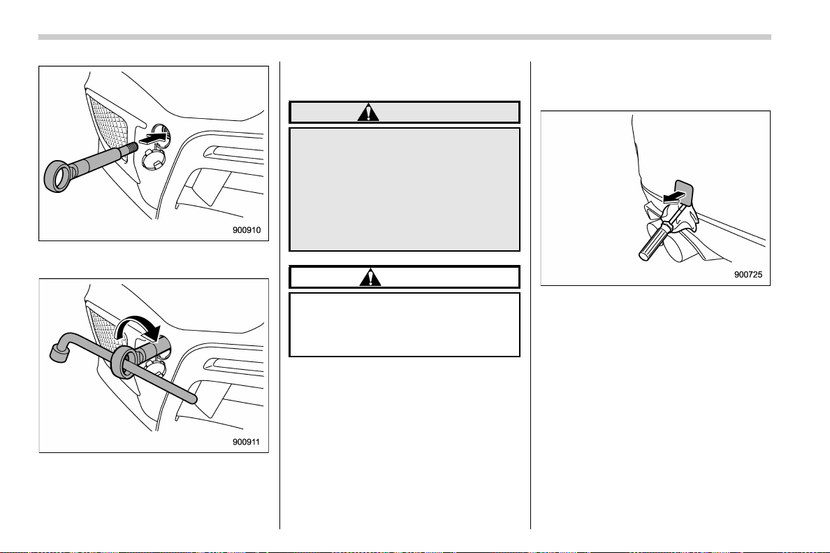
(480,1)
北米Model "A1700BE-B" EDITED: 2017/ 10/ 11
3. Screw the towing hook into the thread
hole until its thread can no longer be seen.
4. Tighten the towing hook securely using
the wheel nut wrench.
After towing, remove the towing hook from
the vehicle and stow it in the tool bucket.
Fit the towing hook cover on the bumper.
WARNING
. Do not use the towing hook
except when towing your vehicle.
. Be sure to remove the towing
hook after towing. Leaving the
towing hook mou nted on the
vehicle could interfere with prop-
er operation of the SRS airbag
system in a frontal collision.
CAUTION
To prevent deformation to the bum-
per and the towing hook, do not
apply an excessive load to the tow-
ing hook.
Rear towing hook:
1. Take the towing hook, screwdriver and
wheel nut wrench out of the tool bucket.
2. Pry off the cover on the rear bumper
using a screwdriver, and you will find a
threaded hole for attaching the towing
hook.
In case of emergency/Towing
9-22
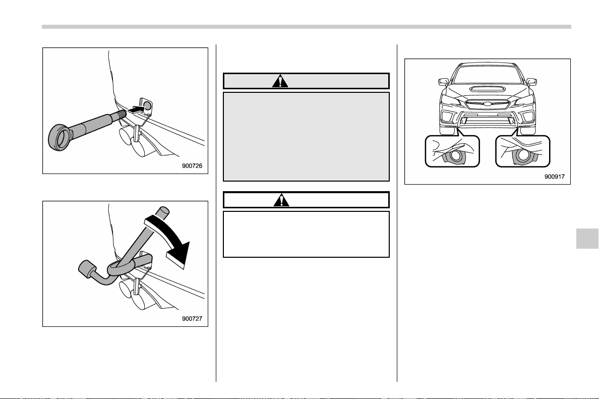
(481,1)
北米Model "A1700BE-B" EDITED: 2017/ 10/ 11
3. Screw the towing hook into the thread
hole until its thread can no longer be seen.
4. Tighten the towing hook securely using
the wheel nut wrench.
After towing, remove the towing hook from
the vehicle and stow it in the tool bucket.
Fit the towing hook cover on the bumper.
WARNING
Do not use the towing hook except
when towing your vehicle.
Be sure to remove the towing hook
after towing. Leaving the towing
hook mounted on the vehicle could
interfere with proper operation of
the fuel pump shut off function when
the vehicle is struck from behind.
CAUTION
To prevent deformation to the bum-
per and the towing hook, do not
apply an excessive load to the tow-
ing hook.
Front tie-down hooks:
The front tie-down hooks are l ocat ed
between each of the front tires and the
front bumper.
– CONTINUED –
In case of emergency/Towing
9-23
9
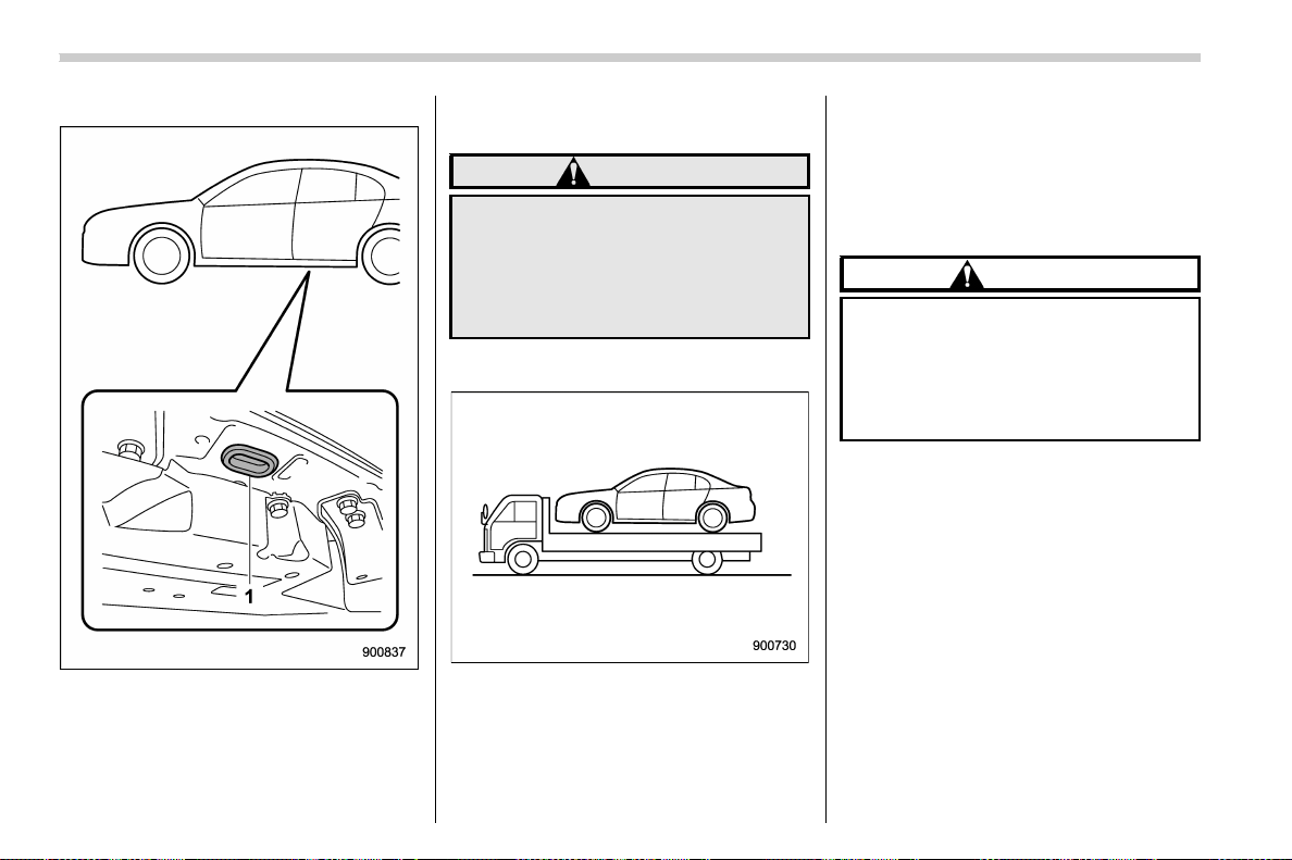
(482,1)
北米Model "A1700BE-B" EDITED: 2017/ 10/ 11
Rear tie-down holes:
1) Rear tie-down hole
The rear tie-down holes are located near
each of the jack-up reinforcements.
There is a plug in each rear tie-down hole.
To use the rear tie-down holes, remove the
plugs. After using the rear tie-down holes,
return the plugs to their original places.
WARNING
Use the rear tie-down holes only for
downward anchoring. If they are
used to anchor the vehicle in any
other direction, cables may slip out
of the holes, possibly causing a
dangerous situation.
& Using a flat-bed truck
This is the best way to transport your
vehicle. Use the following procedures to
ensure safe transportation.
1. Shift the select lever into the “P”
position for CVT models. Shift the shift
lever into the “1st” position for MT models.
2. Apply the parking brake firmly.
3. Secure the vehicle onto the carrier
properly with safety chains. Each safety
chain should be equally tightened and care
must be taken not to pull the chains so
tightly that the suspension bottoms out.
CAUTION
If your vehicle has a front under-
spoiler and rear underspoiler (both
optional), be careful not to scrape
them when placing the vehicle on
the carrier and when removing the
vehicle from the carrier.
In case of emergency/Towing
9-24
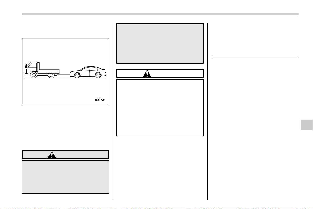
(483,1)
北米Model "A1700BE-B" EDITED: 2017/ 10/ 11
& Towing with all wheels on the
ground
1. Release the parking brake and put the
transmission in the “N”/neutral position.
2. The ignition switch should be in the
“ON” position while the vehicle is being
towed.
3. Take up slack in the towline slowly to
prevent damage to the vehicle.
WARNING
. Never turn the ignition switch to
the “LOCK”/“OFF” position while
the vehicle is being towed be-
cause the steering wheel and the
direction of the wheels will be
locked.
. Remember that the brake booster
and power steering do not func-
tion when the engine is not run-
ning. Because the engine is
turned off, it will take greater
effort to operate the brake pedal
and steering wheel.
CAUTION
. If transmission failure occurs,
transport your vehicle on a flat-
bed truck.
. For CVT models, the traveling
speed must be limited to less
than 20 mph (32 km/h) and the
traveling distance to less than 31
miles (50 km). For greater speeds
and distances, transport your
vehicle on a flat-bed truck.
Electronic parking brake – if
the electronic parking brake
cannot be released (models
with electronic parking brake
system)
Contact your SUBARU dealer and have
your SUBARU dealer release the electro-
nic parking brake.
In case of emergency/Electronic parking brake – if the electronic parking brake cannot be released (models with electronic parking
brake system)
9-25
9
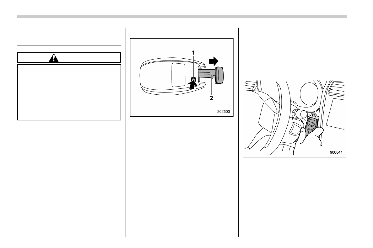
(484,1)
北米Model "A1700BE-B" EDITED: 2017/ 10/ 11
Access key fob – if access key
fob does not operate properly
CAUTION
Keep metallic objects, magnetic
sources and signal transmitters
away from the area between the
access key fob and the push-button
ignition switch. They may interfere
with the communication between
the access key fob and the push-
button ignition switch.
The following functions may be inoperable
because of strong radio signals in the
surrounding area or a low battery condition
of the access key fob.
. Locking/unlocking doors
. Switching power status
. Starting the engine
In such cases, perform the following
procedure. When the battery of the access
key fob is discharged, replace it with a new
one. Refer to “Replacing battery of access
key fob” F11-52.
& Locking and unlocking
1) Release button
2) Emergency key
While pressing the release button of the
access key fob, take out the emergency
key.
Lock or unlock the driver’s door with the
emergency key.
NOTE
After locking or unlocking, be sure to
reinsert the emergency key into the
access key fob.
& Switching power status
1. Apply the parking brake.
2. Shift the shift lever into neutral (MT
models) or the select lever into the “P”
position (CVT models).
3. Depress the clutch pedal (MT models)
or brake pedal (CVT models).
4. Hold the access key fob with the
buttons facing you, and touch the push-
button ignition switch with it.
When the communication between the
access key fob and the vehicle is com-
pleted, a chime (ding) will sound. At the
same time, the status of the push-button
ignition switch changes to either of the
following.
. When the keyless access with push-
button start system is deactivated:
In case of emergency/Access key fob – if access key fob does not operate properly
9-26
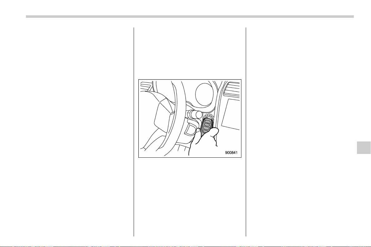
(485,1)
北米Model "A1700BE-B" EDITED: 2017/ 10/ 11
“ACC”
. Under other conditions: “ON”
5. When the keyless access with push-
button start system is deactivated, press
the push-button ignition switch with the
clutch pedal (MT models) or brake pedal
(CVT models) released. The status of the
push-button ignition switch then changes
to “ON”.
NOTE
If the power does not switch even
though the above procedure was fol-
lowed precisely, contact your SUBARU
dealer.
& Starting engine
1. Apply the parking brake.
2. Shift the shift lever into neutral (MT
models) or the select lever into the “P”
position (CVT models).
3. Depress the brake pedal (all models).
4. Depress the clutch pedal (MT models).
5.Holdtheaccesskeyfobwiththe
buttons facing you, and touch the push-
button ignition switch with it.
When the communication between the
access key fob and the vehicle is com-
pleted, a chime (ding) will sound. At the
same time, the push-button ignition switch
turns to the “ACC” or “ON” position.
6. Within 5 seconds after the push-button
ignition switch turns to the “ACC” or “ON”
position, while depressing the brake pedal
(all models) and the clutch pedal (MT
models), press the push-button ignition
switch.
NOTE
If the engine does not start even though
the above procedure was followed
precisely, contact your SUBARU dealer.
In case of emergency/Access key fob – if access key fob does not operate properly
9-27
9
(486,1)
北米Model "A1700BE-B" EDITED: 2017/ 10/ 11
Moonroof (if equipped) – if the
moonroof does not close
If the moonroof doe s not cl ose, we
recommend that you have the system
checked by a SUBARU dealer.
If your vehicle is involved in
an accident
CAUTION
If your vehicle is inv olved in an
accident, be sure to inspect the
ground under the vehicle before
restarting the engine. If you find that
fuel has leaked on the ground, do
not try to restart the engine. The fuel
system has been damaged and is in
need of repair. Immediately contact
the nearest automotive service facil-
ity. We recommend that you consult
your SUBARU dealer.
Your vehicle has a fuel pump shut off
system. To minimize the risk of fire due to
fuel leakage when your vehicle is subject
to impact from an accident or another
factor, the system stops supplying fuel.
However, depending on the impact condi-
tions at the time of collision, the fuel pump
shut-off system may not operate.
Perform the following procedures to restart
the engine after the system is activated.
Models without “keyless access with
push-button start system”:
1. Turn the ignition switch to the “ LOCK”
or “ACC” position.
2. Restart the engine.
Models with “keyless access with
push-button start system”:
1. Turn the push-button ignition switch to
the “ACC” or “OFF” position.
2. Restart the engine.
In case of emergency/Moonroof – if the moonroof does not close
9-28

(489,1)
北米Model "A1700BE-B" EDITED: 2017/ 10/ 11
Exterior care.......................................................... 10-2
Washing ...............................................................10-2
Waxing and polishing............................................ 10-4
Cleaning alloy wheels ........................................... 10-4
Corrosion protection ............................................ 10-5
Most common causes of corrosion .......................10-5
To help prevent corrosion .....................................10-5
Cleaning the interior ............................................. 10-6
Seat fabric ............................................................ 10-6
Leather seat materials .......................................... 10-6
Synthetic leather upholstery .................................10-6
Climate control panel, audio panel, instrument
panel, console panel, and switches....................10-7
Monitor................................................................. 10-7
Steering wheel with ultra-suede covering
(if equipped) ....................................................... 10-7
Regular cleaning...................................................10-7
Liquid dirt.............................................................10-8
Dirt from hands .................................................... 10-8
Appearance care
10
(490,1)
北米Model "A1700BE-B" EDITED: 2017/ 10/ 11
Exterior care
& Washing
CAUTION
TYPE RA: Do not use automatic car
washes. Doing so may damage the
rear wing or its finish.
CAUTION
. When washing the vehicle, the
brakes may get wet. As a result,
the brake stopping distance will
be longer. To dry the brakes, drive
the vehicle at a safe speed while
lightly depressing the brake ped-
al to heat up the brakes.
. Do not wash the engine compart-
ment and area adjacent to it. If
water enters the engine air intake
or electrical parts, it will cause
engine trouble or a malfunction
of electrical equipment.
. When washing the inner fenders,
underbody, bumpers and pro-
truding objects such as exhaust
pipes and exhaust finishers, be
careful to prevent injuries from
contacting sharp ends.
. Do not use any organic solvents
when washing the surface of the
bulb assembly cover. However, if
a detergent with organic solvents
is used to wash the cover sur-
face, completely rinse off the
detergent with water. Otherwise,
the cover surface may be da-
maged.
NOTE
When having your vehicle washed in an
automatic car wash, make sure before-
hand that the car wash is of suitable
type.
The best way to preserve your vehicle’s
beauty is frequent washing. Wash the
vehicle at least once a month to avoid
contamination by road grime.
Wash dirt off with a wet sponge and plenty
of lukewarm or cold water. Do not wash the
vehicle with hot water and in direct sun-
light.
Salt, chemicals, insects, tar, soot, tree sap,
and bird droppings should be washed off
by using a light detergent, as required. If
you use a light detergent, make certain
that it is a neutral detergent. Do not use
strong soap or chemical detergents. All
cleaning agents should be promptly rinsed
off the surface and not allowed to dry there.
Rinse the vehicle thoroughly with plenty of
lukewarm water. Wipe the remaining water
off with a chamois or soft cloth. Wear
rubber gloves and use a hand brush when
washing down underbody, inner fenders
and suspension to effectively remove mud
and dirt off.
! Washing the underbody
Chemicals, salts and gravel used for
deicing road surfaces are extremely cor-
rosive, accelerating the corrosion of un-
derbody components, such as the exhaust
system, fuel and brake lines, brake cables,
floor pan and fenders, and suspension.
Thoroughly flush the underbody and inside
of the fenders with lukewarm or cold water
at frequent intervals to reduce the harmful
effects of such agents.
Mud and sand adhering to the underbody
components may accelerate their corro-
sion.
After driving off-road or on muddy or sandy
roads, wash the mud and sand off the
underbody. Carefully flush the suspension
and axle parts, as they are particularly
prone to mud and sand buildup. Do not use
a sharp-edged tool to remove caked mud.
Appearance care/Exterior care
10-2
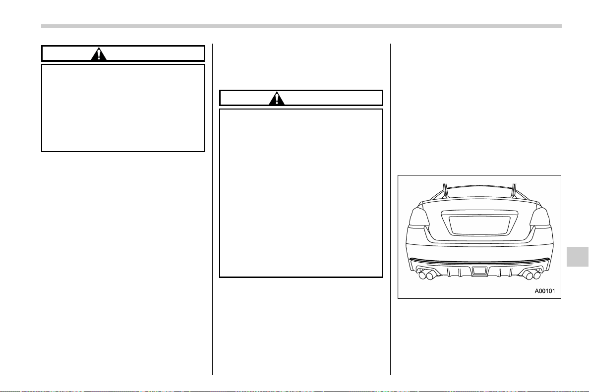
(491,1)
北米Model "A1700BE-B" EDITED: 2017/ 10/ 11
CAUTION
. Be careful not to damage brake
hoses, sensor harnesses, and
other parts when washing sus-
pension components.
. Be careful not to flush the engine
bottom for a long time. It may
cause damage of some electrical
parts.
! Using a warm water washer
. Keep a good distance of 12 in (30 cm)
or more between the washer nozzle and
the vehicle.
. Do not wash the same area continu-
ously.
. If a stain will not come out easily, wash
by hand. Some warm water washers are of
the high temperature, high pressure type,
and they can damage or deform the resin
parts such as moldings, or cause water to
leak into the vehicle.
! Precautions for TYPE RA
! Precautions when cleaning the
carbon roof and rear wing
CAUTION
. When cleaning, take care that you
do not apply strong force to a
single point. Depending on the
degree of force and the location,
there is the risk of denting the
carbon roof or rear wing.
. After acid rain falls, it is recom-
mended that the vehicle be
washed before the water on the
paint evaporates.
. Promptly wash off any bird drop-
pings, insects, pollen, tree sap, or
similar substance that adheres to
the paint. If it is not promptly
washed off, it may penetrate the
paint.
. Remove any dirt using a neutral deter-
gent. Do not use hard brushes or abrasive
cleaners. Do not use strong or harsh
chemical cleaners.
. As the CFRP parts may change color if
they are exposed to ultraviolet rays for
extended periods of time, we recommend
that your vehicle be stored in a place
where it will not be exposed to direct
sunlight.
. Do not use wax that contains abrasives.
NOTE
Due to the characteristics of the carbon
roof, white cloudy areas may occur in
spots on the roof, however these do not
affect performance in any way.
! Precautions when cleaning
around the rear bumper cherry
red stripe
Rear bumper cherry red stripe
Precautions when using a high-pres-
sure washer:
. Keep a distance of 12 in (30 cm) or
more between the washer nozzle and the
stripe.
– CONTINUED –
Appearance care/Exterior care
10-3
10
(492,1)
北米Model "A1700BE-B" EDITED: 2017/ 10/ 11
. Do not continually wash the same
location.
. If using a high-temperature, high-pres-
sure washer, avoid cleaning the stripe.
Doing so may cause the stripe to peel off.
Precautions when using a solvent to
wash the car:
. Some solvents may adversely affect
seal adhesion performance. Be sure to
check the precautions listed on the solvent
before using it.
. If dirt is difficult to remove, a neutral
detergent diluted with water should be
used to carefully wipe off the dirt.
& Waxing and polishing
Always wash and dry the vehicle before
waxing and polishing.
Use a good quality polish and wax and
apply them according to the manufac-
turer’s instructions. Wax or polish when
the painted surface is cool.
Be sure to polish and wax the chrome trim,
as well as the painted surfaces. Loss of
wax on a painted surface leads to loss of
the original luster and also quickens the
deterioration of the surface. It is recom-
mended that a coat of wax be applied at
least once a month, or whenever the
surface no longer repels water.
If the appearance of the paint has dimin-
ished to the point where the luster or tone
cannot be restored, lightly polish the sur-
face with a fine-grained compound. Never
polish just the affected area, but include
the surrounding area as well. Always
polish in only one direction. A No. 2000
grain compound is recommended. Never
use a coarse-grained compound. Coarse-
grained compounds have a smaller grain-
size number and could damage the paint.
After polishing with a compound, coat with
wax to restore the original luster. Frequent
polishing with a compound or an incorrect
polishing technique will result in removing
the paint layer and exposing the under-
coat. When in doubt, it is always best to
contact your SUBARU dealer or an auto
paint specialist.
CAUTION
Do not use any agents with organic
solvents on the surface of the bulb
assembly cover. However, if a polish
or wax with organic solvents is
applied to the cover surface, com-
pletely wipe off the polish or wax.
Otherwise, the cover surface may be
damaged.
NOTE
Be careful not to block the windshield
washer nozzles with wax when waxing
the vehicle.
& Cleaning alloy wheels
. Promptly wipe the alloy wheels clean of
any kind of grime or agent. If dirt is left on
too long, it may be difficult to clean off.
. Do not use soap containing grit to clean
the wheels. Be sure to use a neutral
cleaning agent, and later rinse thoroughly
with water. Do not clean the wheels with a
stiff brush or expose them to a high-speed
washing device.
. Clean the vehicle (including the alloy
wheels) with water as soon as possible
when it has been splashed with sea water,
exposed to sea breezes, or driven on
roads treated with salt or other agents.
Appearance care/Exterior care
10-4

(493,1)
北米Model "A1700BE-B" EDITED: 2017/ 10/ 11
Corrosion protection
Your SUBARU has been designed and
built to resist corrosion. Special materials
and protective finishes have been used on
most parts of the vehicle to help maintain
fine appearance, strength, and reliable
operation.
& Most common causes of cor-
rosion
The most common causes of corrosion
are:
. The accumulation of moisture retaining
dirt and debris in body panel sections,
cavities, and other areas.
. Damage to paint and other protective
coatings caused by gravel and stone chips
or minor accidents.
Corrosion is accelerated on the vehicle
when:
. It is exposed to road salt or dust control
chemicals, or used in coastal areas where
there is more salt in the air, or in areas
where there is considerable industrial
pollution.
. It is driven in areas of high humidity,
especially when temperatures range just
above freezing.
. Dampness in certain parts of the
vehicle remains for a long time, even
though other parts of the vehicle may be
dry.
. High temperatures will cause corrosion
to parts of the vehicle which cannot dry
quickly due to lack of proper ventilation.
& To help prevent corrosion
Wash the vehicle regularly to prevent
corrosi on of the body and suspension
components. Also, wash the vehicle
promptly after dri ving on any of t he
following surfaces.
. roads that have been salted to prevent
them from freezing in winter
. mud, sand, or gravel
. coastal roads
After the winter has ended, it is recom-
mended that the underbody be given a
very thorough washing.
Before the beginning of winter, check the
condition of underbody components, such
as the exhaust system, fuel and brake
lines, brake cables, suspension, steering
system, floor pan, and fenders. If any of
them are found to be rusted, they should
be given an appropriate rust prevention
treatment or should be replaced. Contact
your SUBARU dealer to perform this kind
of maintenance and treatment if you need
assistance.
Repair chips and scratches in the paint as
soon as you find them.
Check the interior of the vehicle for water
and dirt accumulation under the floor mats
because that could cause corrosion. Oc-
casionally check under the mats to make
sure the area is dry.
Keep your garage dry. Do not park your
vehicle in a damp, poorly ventilated gar-
age. In such a garage, corrosion can be
caused by dampness. If you wash the
vehicle in the garage or put the vehicle into
the garage when wet or covered wi th
snow, that can cause dampness.
If your vehicle is operated in cold weather
and/or in areas where road salts and other
corrosive materials are used, the door
hinges and locks, and hood latch should
be inspected and lubricated periodically.
Appearance care/Corrosion protection
10-5
10
(494,1)
北米Model "A1700BE-B" EDITED: 2017/ 10/ 11
Cleaning the interior
Use a soft, damp cloth to clean the climate
control panel, audio equipment, instru-
ment panel, center console, combination
meter panel, and switches. (Do not use
organic solvents.)
& Seat fabric
Remove loose dirt, dust or debris with a
vacuum cleaner. If the dirt is caked on the
fabric or hard to remove with a vacuum
cleaner, use a soft brush then vacuum it.
Wipe the fabric surface with a tightly wrung
cloth and dry the seat fabric thoroughly. If
the fabric is still dirty, wipe using a solution
of mild soap and lukewarm water then dry
thoroughly.
If the stain does not come out, try a
commercially-available fabric cleaner.
Use the cleaner on a hidden place and
make sure it does not affect the fabric
adversely. Use the cleaner according to its
instructions.
CAUTION
When cleaning the seat, do not use
benzine, paint thinner, or any similar
materials. Doing so could damage
the surface and cause the color to
deteriorate.
& Leather seat materials
The leather used by SUBARU is a high
quality natural product which will retain its
distinctive appearance and feel for many
years with proper care.
Allowing dust or road dirt to build up on the
surface can cause the material to become
brittle and to wear prematurely. Regular
cleaning with a soft, moist, natural fiber
cloth should be performed monthly, taking
care not to soak the leather or allow water
to penetrate the stitched seams.
A mild detergent suitable for cleaning
woolen fabrics may be used to remove
difficult dirt spots, rubbing with a soft, dry
cloth afterwards to restore the luster. If
your SUBARU is to be parked for a long
time in bright sunlight, it is recommended
that the seats and head restraints be
covered, or the windows shaded, to pre-
vent fading or shrinkage. Make sure to
remove any seat covers and head restraint
covers when operating the vehicle.
Minor surface blemishes or bald patches
may be treated with a commercial leather
spray lacquer. You will discover that each
leather seat section will develop soft folds
or wrinkles, which is characte risti c of
genuine leather.
& Synthetic leather upholstery
The synthetic leather material used on the
SUBARU may be cleaned using mild soap
or detergent and water, after first vacuum-
ing or brushing away loose dirt. Allow the
soap to soak in for a few minutes and wipe
off with a clean, damp cloth. Commercial
foam-type cleaners suitable for synthetic
leather materials may be used wh en
necessary.
CAUTION
Strong cleaning agent s such as
solvents, paint thinners, window
cleaner or fuel must never be used
on leather or synthetic interior ma-
terials. Doing so could damage the
surface and cause the color to
deteriorate.
Appearance care/Cleaning the interior
10-6
(495,1)
北米Model "A1700BE-B" EDITED: 2017/ 10/ 11
& Climate control panel, audio
panel, instrument panel, con-
sole panel, and switches
Use a soft, damp cloth to clean the climate
control panel, audio equipment, instru-
ment panel, center console, combination
meter panel, and switches.
CAUTION
. Do not use organic solvents such
as paint thinners or fuel, or
strong cleaning agents that con-
tain those solvents. Doing so
could damage the surface and
cause the color to deteriorate.
. Do not use chemical solvents that
contain silicone on the vehicle
audio system, electrical compo-
nents of the air-conditioner or
any switches. If silicone adheres
to these parts, it may cause
damage to electrical compo-
nents.
& Monitor
To clean the audio/navigation/multi-func-
tion display monitor, wipe it with a silicone
cloth or with a soft cloth. If the monitor is
extremely dirty, clean it with a soft cloth
moistened with neutral detergent then
carefully wipe off any remaining detergent.
CAUTION
. Do not spray neutral detergent
directly onto the monitor. Doing
so could damage the monitor’s
components.
. Do not wipe the monitor with a
hard cloth. Doing so could
scratch the monitor.
. Do not use cleaning fluid that
contains thinner, fuel, or any
other volatile substance. Such
cleaning fluid could erase the
lettering on the switches at the
bottom of the monitor.
Steering wheel with ultra-
suede covering (if equipped)
In order to maintain the characteristic
texture and appearance of ultra-suede,
regular cleaning of the steering wheel is
recommended.
NOTE
If the steering wheel is used continually
without cleaning, the surface will ap-
pear worn. This is due to dirt from
hands and other sources which causes
the ultra-suede fibers to harden. This is
not a defect.
Follow the procedure below and perform
cleaning.
& Regular cleaning
It is recommended that regular cleaning
(approximately once a month) be per-
formed by following the procedure below.
1. Dampen a cloth or similar item with
warm water at approximately 1048F
(408C), then strongly wring it out and wipe
over the entire steering wheel.
2. When the surface of the ultra-suede is
dry, use a lint brush or similar means to
straighten the fibers.
– CONTINUED –
Appearance care/Steering wheel with ultra-suede covering
10-7
10
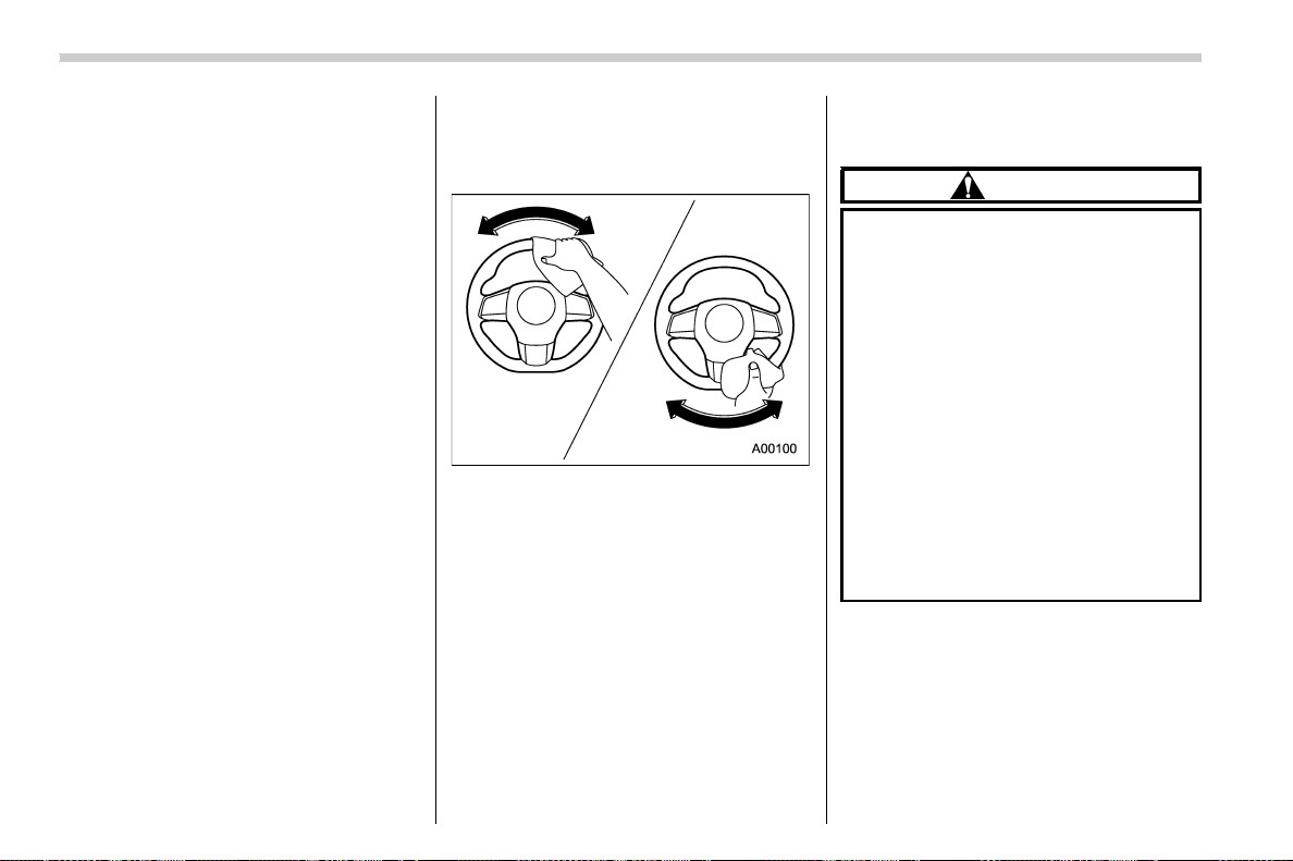
(496,1)
北米Model "A1700BE-B" EDITED: 2017/ 10/ 11
NOTE
. When wiping, be careful not to
strongly disturb the ultra-suede piles.
. Use a clean cloth. When wiping,
rinse the cloth carefully and fully re-
move all dirt from it.
& Liquid dirt
For any spillage cleaning, carry out the
following methods.
. Spilled liquids: Use tissue paper or
similar material to gently absorb the liquid.
. If mud, coffee, or other dirt hardens
after drying, use a lint brush or similar
means and gently brush the spot to
remove the dirt.
If the dirt cannot be removed after per-
forming the above cleaning, refer to “Dirt
from hands” F10-8.
& Dirt from hands
If the texture or appearance has been
diminished by dirt from hands or other
sources, follow the procedure below for
cleaning.
Items to prepare:
A) Cloth dampened with neutral detergent
solution (5 - 10%) and strongly wrung out
B) Cloth dampened with warm water at
approximately 1048F (408C)
Procedure:
1. Use a lint brush or similar means and
gently brush to remove adhering dust and
dirt.
2. Use the cloth that was dampened with
neutral detergent solution (5 - 10%) and
strongly wrung out (A) and grip the steer-
ing wheel with it, then wipe by moving the
cloth around the steering wheel as shown
in the figure.
3. In order to remove the remaini ng
neutral detergent on the ultra-suede, use
the cloth that was dampened with warm
water at approximately 1048F (408C) (B) to
grip the steering wheel with it, then wipe by
moving the cloth around the steering
wheel. Rinse the cloth with warm water
and repeat this step 3 times.
4. If the surface piles become disturbed,
brush gently using a lint brush or similar
means.
CAUTION
. Do not use benzene, gasoline, or
other organic solvent, acidic or
alkaline detergents, dyes, bleach,
or similar substances. Doing so
may cause discoloration, wrin-
kles, or peeling of the paint.
. Do not use commercially avail-
able cleaners. They may contain
components that cause disco-
loration, wrinkles, and paint to
peel off.
. Strongly wring out the cloth dam-
pened with the neutral detergent
solution or warm water. If water
or detergent enters the steering
wheel switches or airbag, there is
the risk of causing malfunctions.
Appearance care/Steering wheel with ultra-suede covering
10-8

(499,1)
北米Model "A1700BE-B" EDITED: 2017/ 10/ 11
Maintenance schedule.......................................... 11-3
Maintenance precautions ..................................... 11-3
Before checking or servicing in the engine
compartment ...................................................... 11-4
When checking or servicing in the engine
compartment ...................................................... 11-5
When checking or servicing in the engine
compartment while the engine is running ............ 11-5
Maintenance tips................................................... 11-6
Removing and reinstalling clips ............................11-6
Engine hood .......................................................... 11-9
Engine compartment overview .......................... 11-11
STI...................................................................... 11-11
Except STI .......................................................... 11-12
Engine oil............................................................. 11-13
Engine oil consumption ...................................... 11-13
Checking the oil level.......................................... 11-13
Changing the oil and oil filter .............................. 11-15
Recommended grade and viscosity ..................... 11-15
Synthetic oil........................................................ 11-16
Cooling system ................................................... 11-16
Cooling fan, hose and connections ..................... 11-17
Engine coolant.................................................... 11-17
Air cleaner element............................................. 11-18
Replacing the air cleaner element........................ 11-19
Spark plugs ......................................................... 11-21
Recommended spark plugs................................. 11-21
Drive belts ........................................................... 11-21
Manual transmission oil...................................... 11-22
Recommended grade and viscosity..................... 11-22
Continuously variable transmission fluid.......... 11-22
Front differential gear oil (CVT models) and
rear differential gear oil....................................11-23
Recommended grade and viscosity..................... 11-23
Power steering fluid (STI) ...................................11-23
Checking the fluid level ...................................... 11-23
Recommended fluid............................................ 11-24
Brake fluid............................................................11-24
Checking the fluid level ...................................... 11-24
Recommended brake fluid .................................. 11-25
Clutch fluid (MT models).....................................11-25
Checking the fluid level ...................................... 11-25
Recommended clutch fluid ................................. 11-26
Brake booster ......................................................11-26
Brake pedal ..........................................................11-27
Checking the brake pedal free play ..................... 11-27
Checking the brake pedal reserve distance ......... 11-27
Clutch pedal (MT models)...................................11-27
Checking the clutch function .............................. 11-27
Checking the clutch pedal free play .................... 11-28
Hill start assist system .......................................11-28
Replacement of brake pad and lining ................11-28
Breaking-in of new brake pads (models with
electronic parking brake system) ..................... 11-29
Breaking-in of new brake pads and linings
(models without electronic parking brake
system) ........................................................... 11-29
Maintenance and service
11

(500,1)
北米Model "A1700BE-B" EDITED: 2017/ 10/ 11
Parking brake stroke (models without
electronic parking brake system) ................... 11-30
Tires and wheels................................................. 11-30
Types of tires...................................................... 11-30
Tire pressure monitoring system (TPMS)
(if equipped) ..................................................... 11-30
Tire inspection.................................................... 11-32
Tire pressures and wear...................................... 11-32
Wheel balance .................................................... 11-34
Wear indicators................................................... 11-35
Rotational direction of tires ................................. 11-35
Tire rotation........................................................ 11-36
Tire replacement ................................................. 11-36
Wheel replacement ............................................. 11-37
Alloy wheels ........................................................ 11-38
Windshield washer fluid ..................................... 11-38
Replacement of wiper blades ............................ 11-39
Windshield wiper blade assembly........................ 11-40
Windshield wiper blade rubber ............................ 11-40
Battery ................................................................. 11-41
Fuses ....................................................................11-42
Installation of accessories..................................11-44
Replacing bulbs ...................................................11-44
Headlights (models with LED headlights) ............ 11-44
High beam headlight
(models without LED headlights) ..................... 11-44
Low beam headlight*, front side marker light,
parking light* and front turn signal light* ......... 11-46
Front turn signal light
(models with LED headlights) .......................... 11-48
Front fog light
(models with the LED front fog light) ............... 11-48
Front fog light (models without the LED front
fog light) (if equipped) ..................................... 11-49
Rear combination lights...................................... 11-49
License plate light .............................................. 11-50
Other bulbs ........................................................ 11-51
Replacing battery ................................................11-51
Safety precautions.............................................. 11-51
Replacing battery of access key fob ................... 11-52
Replacing transmitter battery.............................. 11-53
Maintenance and service
(501,1)
北米Model "A1700BE-B" EDITED: 2017/ 10/ 11
Maintenance schedule
U.S. models
The scheduled maintenance items re-
quired to be serviced at regular intervals
are shown in the “Warranty and Mainte-
nance Booklet”. For details, read the
separate “Warranty and Maintenance
Booklet”.
Canada models
The scheduled maintenance items re-
quired to be serviced at regular intervals
are shown in the “Warranty and Service
Booklet”. For details, read the separate
“Warranty and Service Booklet”.
Other models
Some items of your vehicle are required to
be serviced at scheduled intervals. For
details about your maintenance schedule,
read the separate “Warranty and Main-
tenance Booklet”.
NOTE
You can set a reminder to be displayed
when a scheduled maintenance item is
almost due. For details, refer to “Main-
tenance settings” F3-59.
Maintenance precautions
When maintenance and service are re-
quired, it is recommended that all work be
done by an authorized SUBARU dealer.
If you perform maintenance and service by
yourself, you should familiarize yourself
with the information provided in this sec-
tion on general maintenance and service
for your SUBARU.
Incorrect or incomplete service could
cause improper or unsafe vehicle opera-
tion. Any problems caused by improper
maintenance and service performed by
you are not eligible for warranty coverage.
WARNING
. Testing of an All-Wheel Drive
model must NEVER be performed
on a si ngle two-wheel dynam-
ometer or similar apparatus. At-
tempting to do so will result in
transmission damage and in un-
controlled vehicle movement and
may cause an accident or injuries
to persons nearby.
. Always select a safe area when
performing maintenance on your
vehicle.
. Always be very careful to avoid
injury when working on the vehi-
cle. Remember that some of the
materials in the vehicle may be
hazardous if improperly used or
handled, for example, battery
acid.
. Your vehicle should only be ser-
viced by persons fully competent
to do so. Serious personal injury
may result to persons not experi-
enced in servicing vehicles.
. Always use the proper tools and
make certain that they are well
maintained.
. Never get under the vehicle sup-
ported only by a jack. Always use
safety stands to support the
vehicle.
. Never keep the engine running in
a poorly ventilated area, such as
a garage or other closed areas.
. Do not smoke or allow open
flames around the fuel or battery.
This will cause a fire.
. Because the fuel system is under
pressure, replacement of the fuel
filter should be performed only
by your SUBARU dealer.
. Wear adequate eye protection to
guard against getting oil or fluids
– CONTINUED –
Maintenance and service/Maintenance schedule
11-3
11
(502,1)
北米Model "A1700BE-B" EDITED: 2017/ 10/ 11
in your eyes. If something does
get in your e yes, thoroughly
wash them out with clean water.
. Do not tamper with the wiring of
the SRS airbag system or seat-
belt pretensioner system, or at-
tempt to take its connectors
apart, as that may activate the
system or it can render it inop-
erative. NEVER use a circuit tes-
ter for this wiring. If your SRS
airbag or seatbelt pretensioner
needs service, consult your near-
est SUBARU dealer.
NOTE
SUBARU does not endorse the use of
non-SUBARU approved flushing sys-
tems and strongly advises against
performing these services on a
SUBARU vehicle. Non-SUBARU ap-
proved flushing systems use chemi-
cals and/or solvents which have not
been tested or approved by SUBARU.
SUBARU warranties do not cover any
part of the vehicle which is damaged by
adding or applying chemicals and/or
solvents other than those approved or
recommended by SUBARU.
& Before checking or servicing
in the engine compartment
WARNING
. Always stop the engine and apply
the parking brake to prevent the
vehicle from moving.
. Always let the engine cool down.
Engine parts become very hot
when the engine is running and
remain hot for some time after the
engine has stopped.
. Do not spill engine oil, engine
coolant, brake fluid or any other
fluid on hot engine components.
This may cause a fire.
. When the ignition switch is in the
“ON” position, the cooling fan
may operate suddenly even when
the engine is stopped. If your
body or clothes come into con-
tact with a rotating fan, that could
result in serious injury. To avoid
risk of injury, perform the follow-
ing precautions.
– Models with push-button start
system:
Always turn the push-button
ignition switch to the “OFF”
position and confirm that the
operation indicator on the
switch is turned off. Then take
the access key fob out from
the vehicle.
– Models without push-button
start system:
Always remove the key from
the ignition switch.
. Before performing any servicing
on a vehicle equipped with a
remote engine start system (a
dealer option) temporarily place
that system in the service mode
to prevent it from unexpectedly
starting the engine.
Maintenance and service/Maintenance precautions
11-4
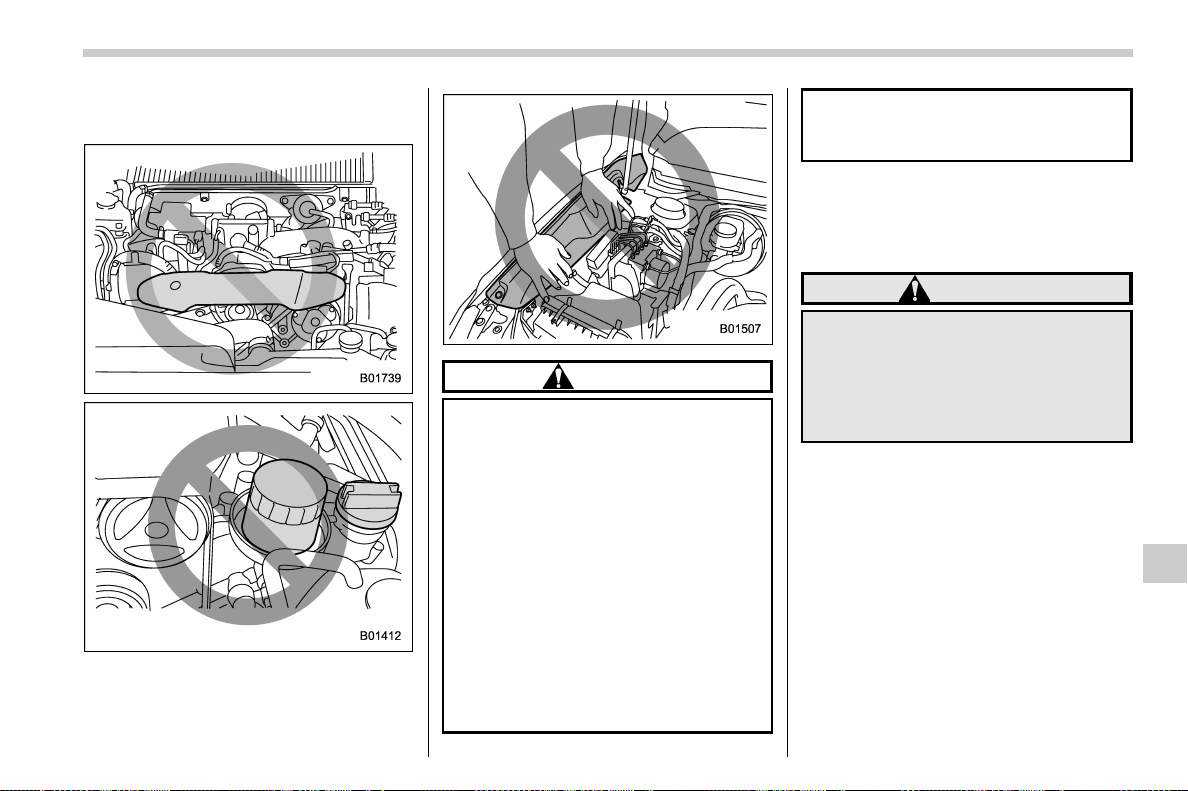
(503,1)
北米Model "A1700BE-B" EDITED: 2017/ 10/ 11
& When checking or servicing
in the engine compartment
CAUTION
. Do not contact the drive belt
cover while checking the compo-
nents in the engine compartment.
Doing so may cause your hand to
slip off the cover and result in an
unexpected injury.
. Do not touch the oil filter until the
engine has cooled down comple-
tely. Doing so may result in a burn
or other injury. Note that the oil
filter becomes very hot when the
engine is running and remains
hot for some time after the engine
has stopped.
. Do not apply force on the fender
insulator by placing your hands
on it, etc. Deformation of the
insulator and its mount may oc-
cur.
& When checking or servicing
in the engine compartment
while the engine is running
WARNING
A running engine can be dangerous.
Keep your fingers, hands, clothing,
hair and tools away from the cooling
fan, drive belt and any other moving
engine parts. Removing rings,
watches and ties is advisable.
Maintenance and service/Maintenance precautions
11-5
11
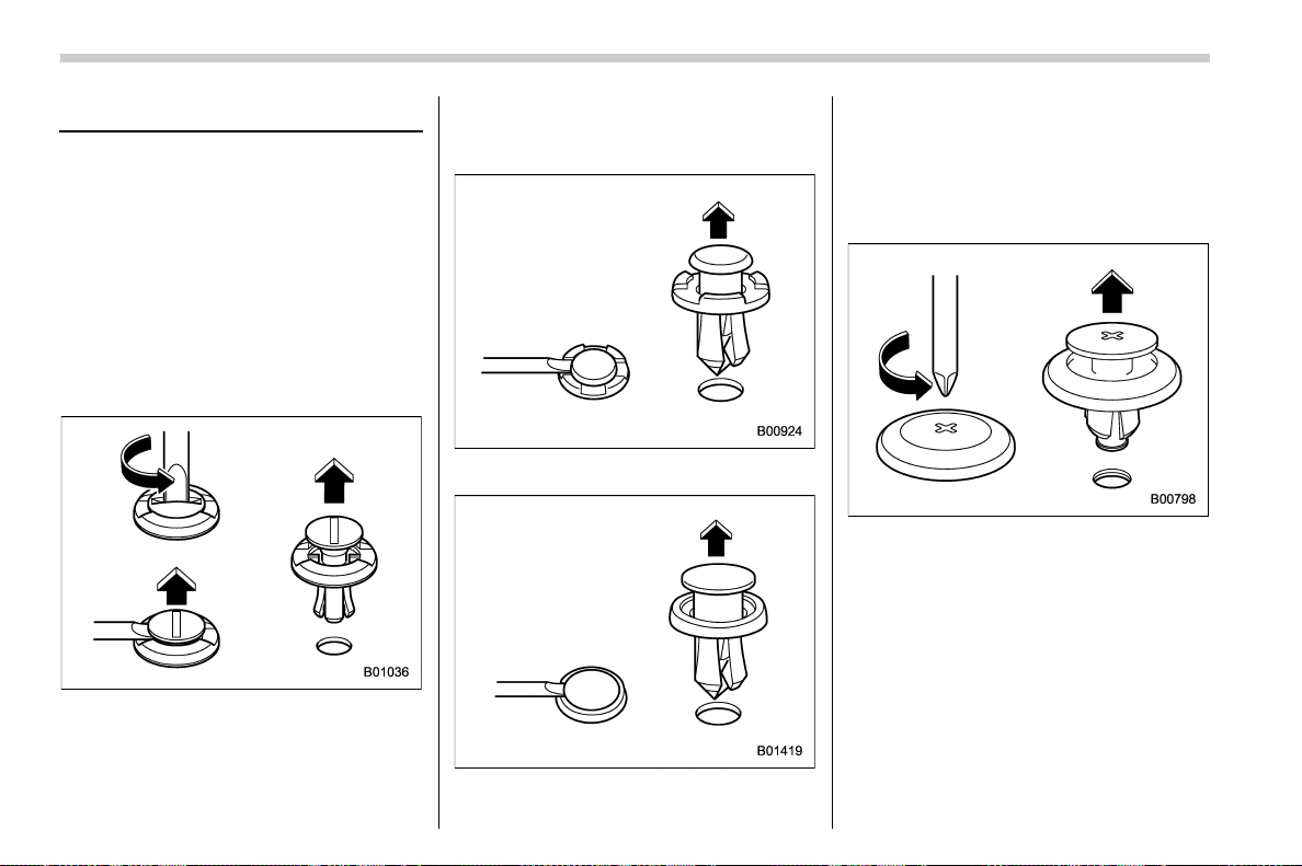
(504,1)
北米Model "A1700BE-B" EDITED: 2017/ 10/ 11
Maintenance tips
Some clips and fender linings must be
removed before replacing the air cleaner
elements or specific bulbs.
& Removing and reinstalling
clips
! Removing clips
There are several types of clips used for
your vehicle.
! Type A clips
1. Turn the clips counterclockwise using
a flat-head screwdriver until the center
portion of the clip is raised.
2. Remove the clips with a flat-head
screwdriver using leverage.
3. Remove the entire clip by pulling it up.
! Type B clips
! Type C clips
1. Pull out the center portion of the clip
using a flat-head screwdriver as shown in
the illustration.
2. Pull the protruded center portion to
remove the entire body of the clip.
! Type D clips
1. Turn the clip counterclockwise using a
Phillips screwdriver until the center portion
of the clip is raised.
2. Remove the entire clip by pulling it up.
Maintenance and service/Maintenance tips
11-6
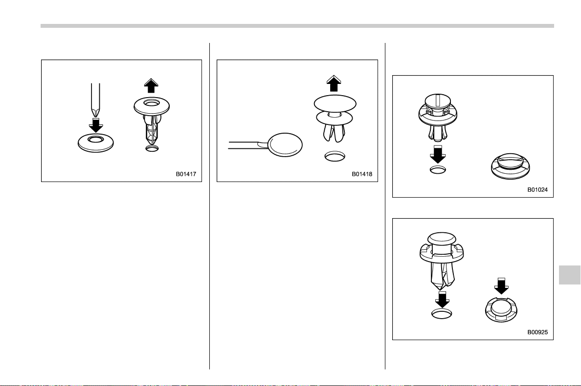
(505,1)
北米Model "A1700BE-B" EDITED: 2017/ 10/ 11
! Type E clips
1. Push the center portion of the clip
using a Phillips screwdriver until the clip is
raised.
2. Remove the entire clip by pulling it up.
! Type F clips
1. Pull out the head of the clip using a flat-
head screwdriver as shown in the illustra-
tion.
2. Remove the entire clip by pulling it up.
! Reinstalling clips
! Type A clips
! Type B clips
– CONTINUED –
Maintenance and service/Maintenance tips
11-7
11
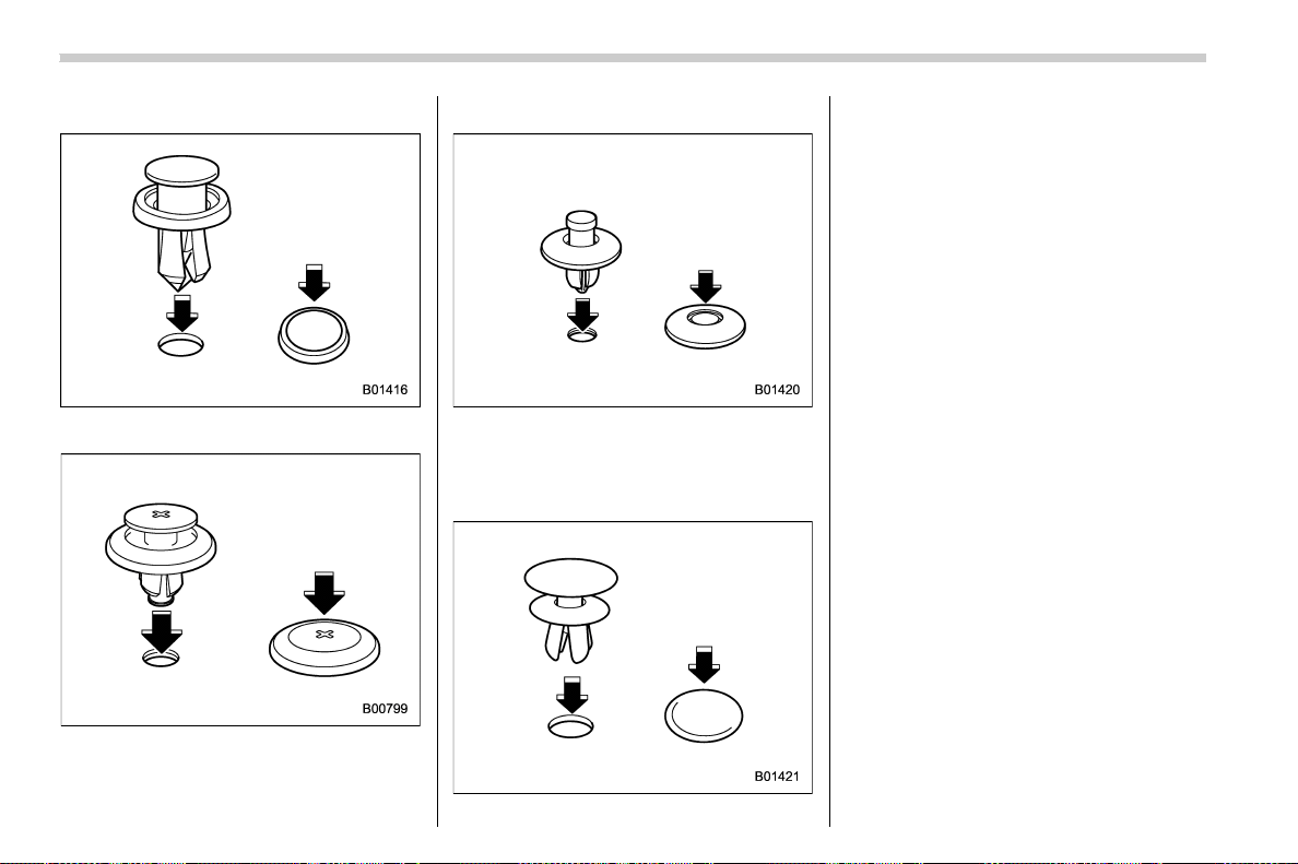
(506,1)
北米Model "A1700BE-B" EDITED: 2017/ 10/ 11
! Type C clips
! Type D clips
! Type E clips
Insert the clip without the center portion
first and then push the center portion of the
clip into the hole.
! Type F clips
Insert the clip without the head first and
then push the head of the clip into the hole.
Maintenance and service/Maintenance tips
11-8
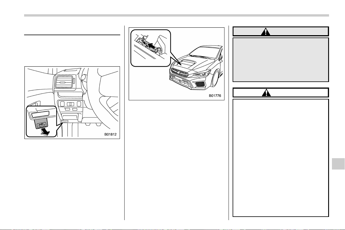
(507,1)
北米Model "A1700BE-B" EDITED: 2017/ 10/ 11
Engine hood
To open the hood:
1. If the wiper blades are lifted off the
windshield, return them to their original
position.
2. Pull the hood lock release knob under
the instrument panel.
3. Release the secondary hood release
by moving the lever between the front grille
and the hood toward the left.
4. Lift up the hood.
To close the hood:
1. Lower the hood to a height of approxi-
mately 11.8 in (30 cm) above its closed
position and then let it drop.
2. After closing the hood, be sure the
hood is securely locked.
If this does not close the hood, release it
from a slightly higher position. Do not push
the hood forcibly to close it. It could deform
the metal.
WARNING
Always check that the hood is
properly locked before you start
driving. If it is not, it might fly open
while the vehicle is moving and
block your view, which may cause
an accident and serious bodily in-
jury.
CAUTION
. When you open the engine hood,
do not stand the wiper blades up.
Furthermore, while the hood is
open, do not operate the wind-
shield wipers. Doing so could
result in damage to the engine
hood and wiper blades.
. Be extremely careful not to catch
fingers or other objects when
closing the engine hood.
. Do not push the hood forcibly to
close it. It could deform the metal.
. Be extremely careful opening the
engine hood when the wind is
strong. The engine hood could
close suddenly, possibly causing
injuries from slamming.
. Do not install accessories other
than genuine SUBARU parts to
– CONTINUED –
Maintenance and service/Engine hood
11-9
11

(508,1)
北米Model "A1700BE-B" EDITED: 2017/ 10/ 11
the engine hood. If the engine
hood becomes too heavy, the
stay may not be able to support
holding it open.
Maintenance and service/Engine hood
11-10
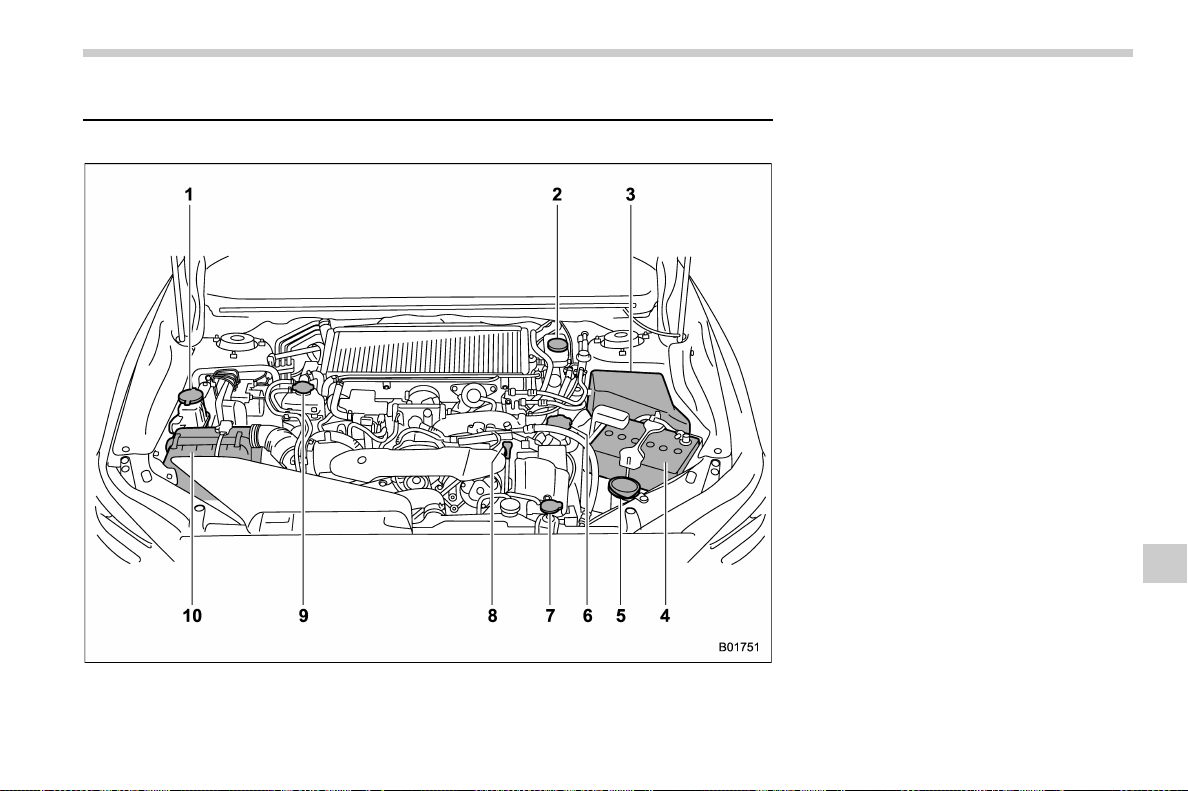
(509,1)
北米Model "A1700BE-B" EDITED: 2017/ 10/ 11
Engine compartment overview
& STI
1) Power steering fluid reservoir
(page 11-23)
2) Brake fluid reservoir/Clutch fluid reservoir
(page 11-24)
3) Fuse box (page 11-42)
4) Battery (page 11-41)
5) Windshield washer tank (page 11-38)
6) Engine oil filler cap (page 11-13)
7) Engine coolant reservoir (page 11-17)
8) Engine oil level gauge (page 11-13)
9) Coolant filler tank cap (page 11-17)
10) Air cleaner case (page 11-18)
– CONTINUED –
Maintenance and service/Engine compartment overview
11-11
11
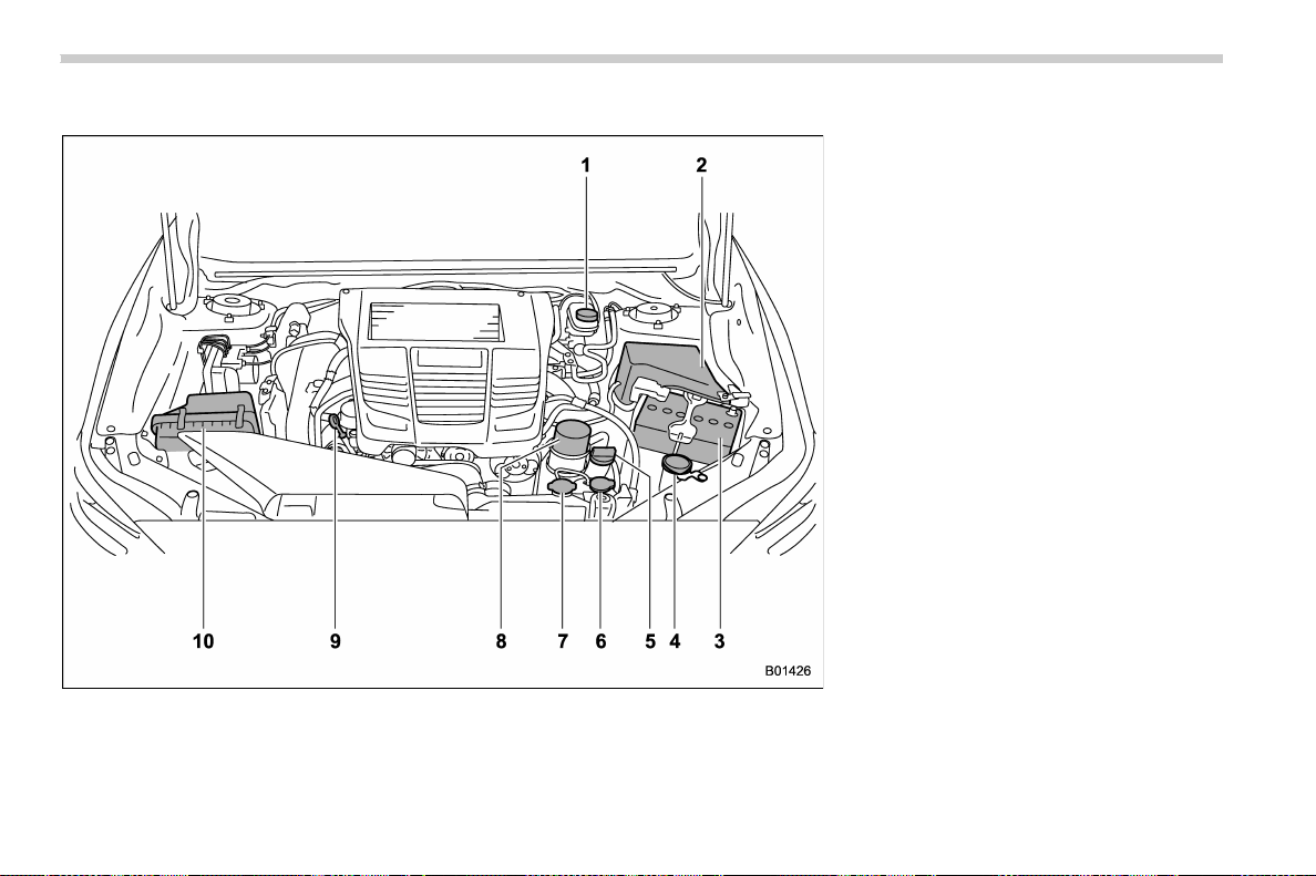
(510,1)
北米Model "A1700BE-B" EDITED: 2017/ 10/ 11
& Except STI
1) Brake fluid reservoir/Clutch fluid reservoir
(MT models) (page 11-24)
2) Fuse box (page 11-42)
3) Battery (page 11-41)
4) Windshield washer tank (page 11-38)
5) Engine oil filler cap (page 11-13)
6) Engine coolant reservoir (page 11-17)
7) Radiator cap (page 11-17)
8) Engine oil filter (page 11-15)
9) Engine oil level gauge (page 11-13)
10) Air cleaner case (page 11-18)
Maintenance and service/Engine compartment overview
11-12
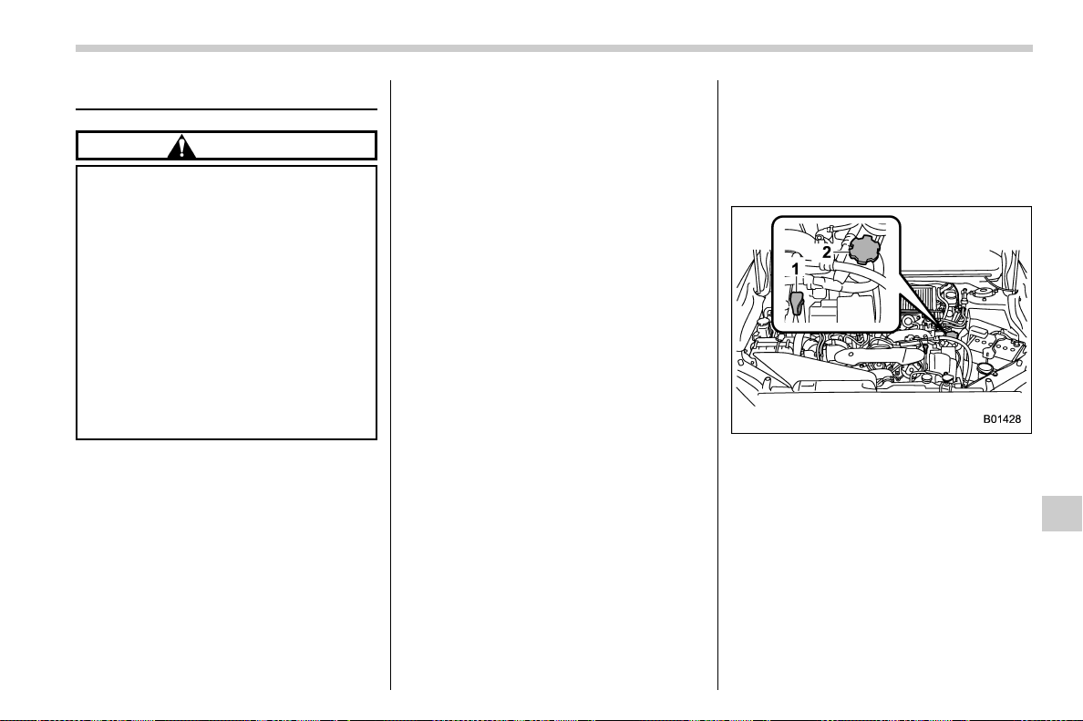
(511,1)
北米Model "A1700BE-B" EDITED: 2017/ 10/ 11
Engine oil
CAUTION
. If the level gauge is not pulled out
easily, twist the level gauge right
and left, then pull it out. Other-
wise, you may be injured acci-
dentally straining yourself.
. Use only engine oil with the
recommended grade and v is-
cosity.
. Be careful not to spill engine oil
when adding it. If oil touches the
exhaust pipe, it may cause a bad
smell, smoke, and/or a fire. If
engine oil gets on the exhaust
pipe, be sure to wipe it off.
& Engine oil consumption
Some engine oil will be consumed while
driving. The rate of consumption can be
affected by such factors as transmission
type, driving style, terrain and tempera-
ture. Under the following conditions, oil
consumption can be increased and thus
require refilling between maintenance in-
tervals:
. When the engine is new and within the
break-in period
. When the engine oil is of lower quality
. When the incorrect oil viscosity is used
. When engine braking is employed
(repeatedly)
. When the engine is operated at high
engine speeds (for extended periods of
time)
. When the engine is operated under
heavy loads (for extended periods of time)
. When the engine idles for extended
periods of time
. When the vehicle is operated in stop
and go and/or heavy traffic situations
. When the vehicle is used under severe
thermal conditions
. When the vehicle accelerates and
decelerates frequently
Under these or similar conditions, you
should check your oil at least every 2nd
fuel fill-up and change your engine oil more
frequently. Different drivers in the same
car may experience different results. If
your oil consumption rate is greater than
expected, contact your authorized
SUBARU retailer who may perform a test
under controlled conditions.
& Checking the oil level
1. Park the vehicle on a level surface and
stop the engine. If you check the oil level
just after stopping the engine, wait a few
minutes for the oil to drain back into the oil
pan before checking the level.
STI
1) Oil level gauge
2) Oil filler cap
– CONTINUED –
Maintenance and service/Engine oil
11-13
11
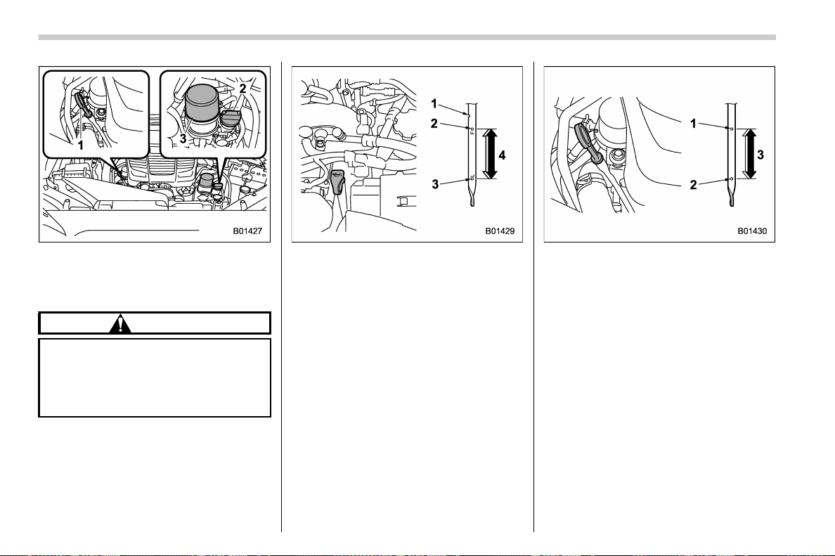
(512,1)
北米Model "A1700BE-B" EDITED: 2017/ 10/ 11
Except STI
1) Oil level gauge
2) Oil filler cap
3) Oil filter
CAUTION
If the level gauge is not pulled out
easily, twist the level gauge right and
left, then pull it out. Otherwise, you
may be injured accidentally strain-
ing yourself.
2. Pull out the level gauge, wipe it clean,
and insert it again.
3. Be sure the level gauge is correctly
inserted until it stops.
STI
1) Notch
2) Full level
3) Low level
4) Approximately 1.1 US qt (1.0 liter, 0.9 Imp
qt) from low level to full level
Except STI
1) Full level
2) Low level
3) Approximately 1.1 US qt (1.0 liter, 0.9 Imp
qt) from low level to full level
4. Pull out the oil level gauge again.
5. STI:
Check the oil level on the gauge. If the oil
level is below the low level mark, add oil so
that the full level is reached.
Except STI:
Check the oil levels on both sides of the
level gauge. Judge the engine oil level by
the lowest of the two levels. If the oil level is
below the low level mark, add oil so that
the full level is reached.
Maintenance and service/Engine oil
11-14
(513,1)
北米Model "A1700BE-B" EDITED: 2017/ 10/ 11
CAUTION
. For models except STI, be careful
not to touch the engine oil filter
when removing the oil filler cap.
Doing so may result in a burn, a
pinched finger, or may cause
some other injury.
. Use only engine oil with the
recommended grade and v is-
cosity.
. Be careful not to spill engine oil
when adding it. If oil touches the
exhaust pipe, it may cause a bad
smell, smoke, and/or a fire. If
engine oil gets on the exhaust
pipe, be sure to wipe it off.
To add engine oil, remove the engine oil
filler cap and slowly pour engine oil
through the filler neck. After pouring oil
into the engine, you must use the level
gauge to confirm that the oil level is
correct.
For models STI, just after driving or while
the engine is warm, the engine oil level
reading may be in a range between the
upper level and the notch mark. This is
caused by thermal expansi on of th e
engine oil.
NOTE
To prevent overfilling the engine oil, do
not add any additional oil above the
upper level when the engine is cold.
& Changing the oil and oil filter
Change the oil and oil filter according to
the maintenance schedule in the “War-
ranty and Maintenance Booklet”.
The engine oil and oil filter must be
changed more frequently than listed in
the maintenance schedule when driving
on dusty roads, when short trips are
frequently made, or when driving in ex-
tremely cold weather.
NOTE
. Changing the engine oil and oil filter
should be performed by a well-trained
expert. Contact your SUBARU dealer
for changing the engine oil and oil filter.
Fully trained mechanics are on standby
at a SUBARU dealer to utilize the
special tools, spare parts and recom-
mended oil for this work, and also, used
oils are properly disposed of.
. If performing oil replacement your-
self, observe the local regulations and
dispose of waste oil properly.
& Recommended grade and
viscosity
CAUTION
Use only engine oil with the recom-
mended grade and viscosity.
Refer to “Engine oil” F12-4.
NOTE
Engine oil viscosity (thickness) affects
fuel economy. Oils of lower viscosity
provide better fuel economy. However,
in hot weather, oil of higher viscosity is
required to properly lubricate the en-
gine.
– CONTINUED –
Maintenance and service/Engine oil
11-15
11
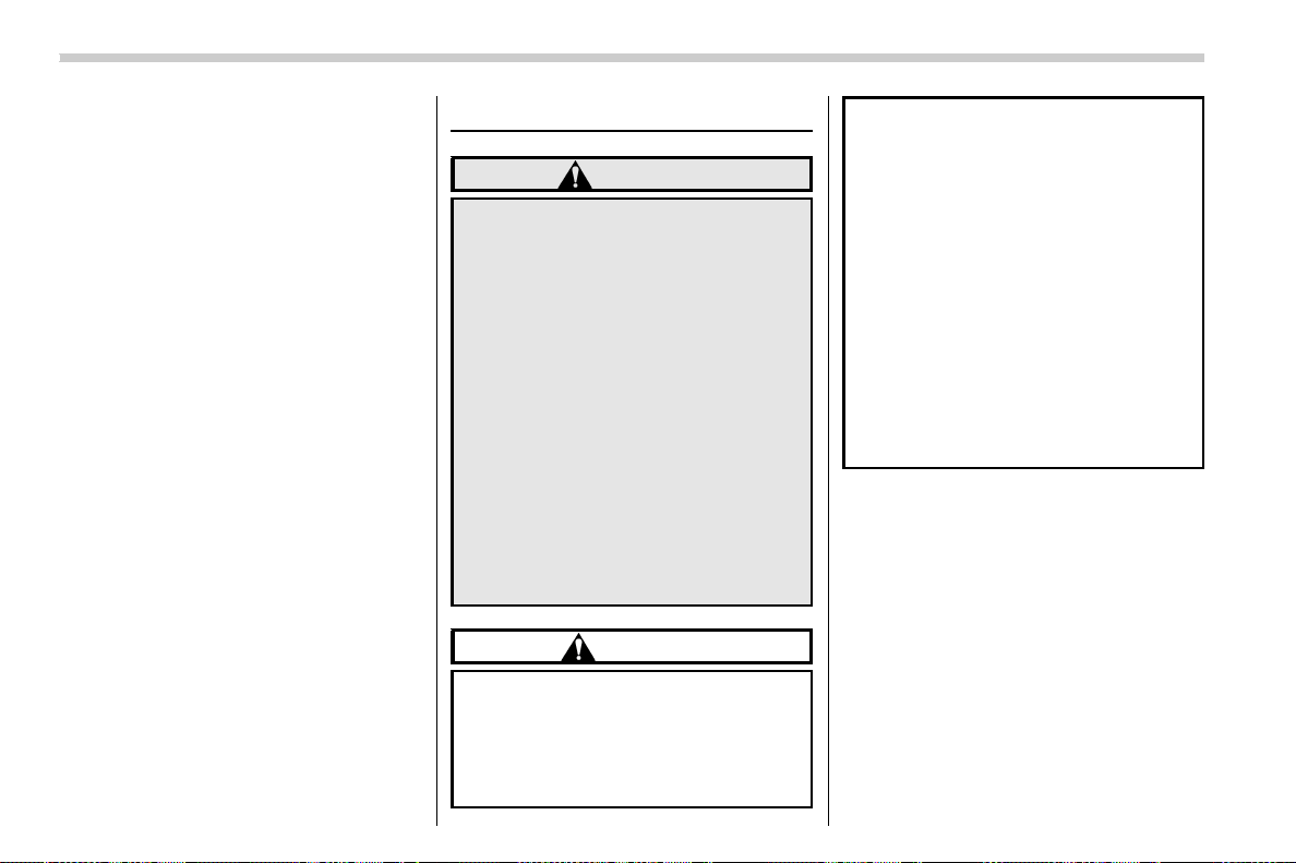
(514,1)
北米Model "A1700BE-B" EDITED: 2017/ 10/ 11
& Synthetic oil
You must follow the oil and filter changing
intervals shown in the Warranty and
Maintenance booklet.
NOTE
Synthetic oil of the grade and viscosity
noted in chapter 12 is the recom-
mended engine oil for optimum engine
performance. Conventional oil may be
used if synthetic oil is unavailable.
Cooling system
WARNING
. Never attempt to remove the
radiator cap until the engine has
been shut off and has cooled
down completely. Since the cool-
ant is under pressure, you may
suffer serious burns from a spray
of boiling hot coolant when the
cap is removed.
. Be careful of the rotating cooling
fan when the engine hood is
open. When the engine tempera-
ture is high, the cooling fan in the
engine compartment may oper-
ate when the ignition switch is in
the “ON” position, even if the
engine is stopped. Touching the
cooling fan while it is rotating
may result in injury.
CAUTION
. Vehicles are filled at the factory
with SUBARU Super Coolant that
does not require the first change
for 11 years/137,500 miles (11
years/220,000 km). Do not mix
this coolant with any other brand
or type of coolant during this
period. Mixing with a different
coolant will reduce the life of the
coolant. Should it be necessary
to top up the coolant for any
reason, use only SUBARU Super
Coolant.
If the SUBARU Super Coolant is
diluted with another brand or
type, the maintenance interval is
shortened to that of the mixing
coolant.
. Do not splash the engine coolant
over painted parts. The alcohol
contained in the engine coolant
may damage the paint surface.
Maintenance and service/Cooling system
11-16
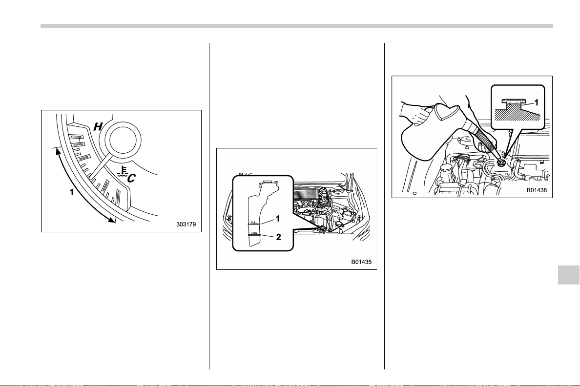
(515,1)
北米Model "A1700BE-B" EDITED: 2017/ 10/ 11
& Cooling fan, hose and con-
nections
Your vehicle employs an electric cooling
fan which is thermostatically controlled to
operate when the engine coolant reaches
a specific temperature.
Temperature gauge
1) Normal operating range
If the radiator cooling fan does not operate
even when the engine coolant tempera-
ture gauge exceeds the normal operating
range, the cooling fan circuit may be
defective. Refer to “Temperature gauge”
F3-11.
Check the fuse and replace it if necessary.
Refer to “Fuses” F11-42 and “Fuses and
circuits” F12-10.
If the fuse is not blown, have the cooling
system checked by your SUBARU dealer.
If frequent addition of coolant is necessary,
there may be a leak in the engine cooling
system. It is recommended that the cooling
system and connections be checked for
leaks, damage, or looseness.
& Engine coolant
! Checking the coolant level
1) “FULL” level mark
2) “LOW” level mark
Check the coolant level at each fuel stop.
1. Check the coolant level on the outside
of the reservoir while the engine is cool.
2. If the level is close to or lower than the
“LOW” level mark, add coolant up to the
“FULL” level mark. If the reserve tank is
empty, remove the radiator cap and refill
coolant up to just below the filler neck as
shown in the following illustration.
STI
1) Fill up to this level
– CONTINUED –
Maintenance and service/Cooling system
11-17
11
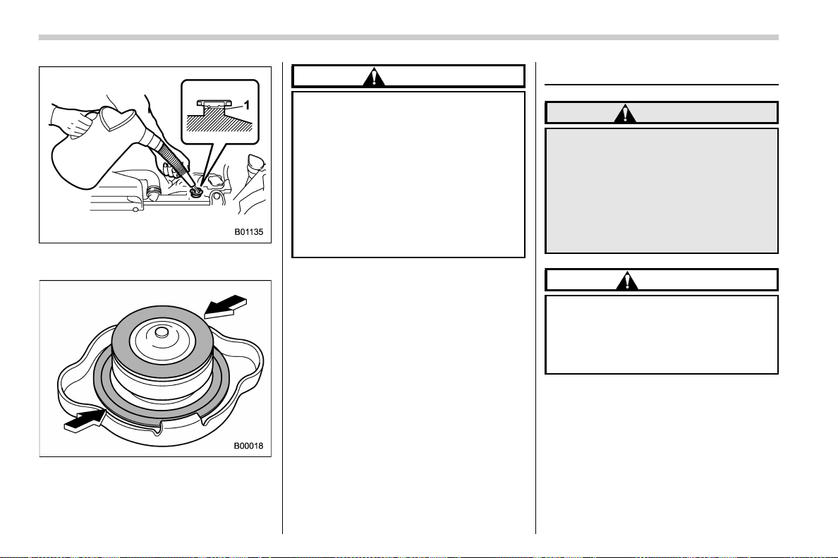
(516,1)
北米Model "A1700BE-B" EDITED: 2017/ 10/ 11
Except STI
1) Fill up to this level
3. After refilling the reserve tank and the
radiator, reinstall the cap and check that
the rubber gaskets inside the radiator cap
are in the proper position.
CAUTION
. Be careful not to spill engine
coolant when adding it. If coolant
touches the exhaust pipe, it may
cause a bad smell, smoke, and/or
a fire. If engine coolant gets on
the exhaust pipe, be sure to wipe
it off.
. Do not splash the engine coolant
over painted parts. The alcohol
contained in the engine coolant
may damage the paint surface.
! Changing the coolant
It may be difficult to change the coolant.
Have the coolant changed by your
SUBARU dealer if necessary.
Have the coolant changed according to the
maintenance schedule in the “Warranty
and Maintenance Booklet”.
Air cleaner element
WARNING
Do not operate the engine with the
air cleaner element removed. The air
cleaner element not only filters in-
take air but also stops flames if the
engine backfires. If the air cleaner
element is not installed when the
engine backfires, you could be
burned.
CAUTION
When replacing the air cleaner ele-
ment, use a genuine SUBARU air
cleaner element. If it is not used,
there is the possibility of causing a
negative effect to the engine.
The air cleaner element functions as a filter
screen. When the element is perforated or
removed, engine wear will be excessive
and engine life shortened.
It is not necessary to clean or wash the air
cleaner element.
Maintenance and service/Air cleaner element
11-18
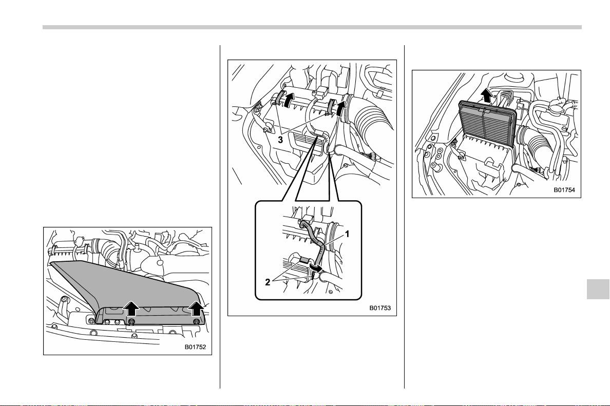
(517,1)
北米Model "A1700BE-B" EDITED: 2017/ 10/ 11
& Replacing the air cleaner ele-
ment
Replace the air cleaner element according
to the maintenance schedule in the “War-
ranty and Maintenance Booklet”. Under
extremely dusty conditions, replace it
more frequently. It is recommended that
you always use genuine SUBARU parts.
! TYPE RA
NOTE
It may be difficult to replace the air
cleaner element. Have the air cleaner
element replaced by your SUBARU
dealer if necessary.
! STI except TYPE RA
1. Use a screwdriver to undo the clips on
the air intake duct, then remove the air
intake duct.
1) Connector cable
2) Guides
3) Clips
2. Remove the connector cable from the
guides of the air cleaner case.
3. Unsnap the two clips holding the air
cleaner case cover.
4. Open the air cleaner case and remove
the air cleaner element.
5. Clean the inside of the air cleaner case
and case cover with a damp cloth and
install a new air cleaner element.
6. Install the removed or loosened parts
in the reverse order of removal.
– CONTINUED –
Maintenance and service/Air cleaner element
11-19
11
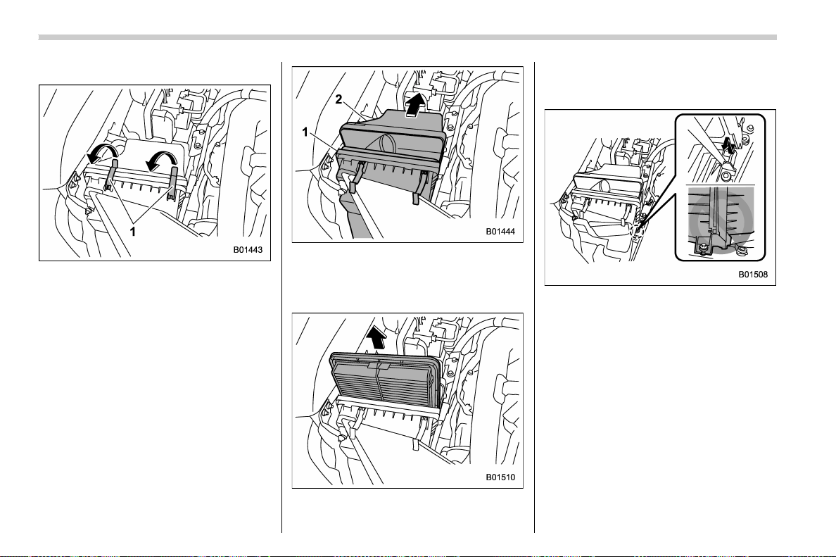
(518,1)
北米Model "A1700BE-B" EDITED: 2017/ 10/ 11
! Except STI
1) Clips
1. Unsnap the two clips holding the air
cleaner case cover.
1) Air cleaner case
2) Air cleaner case cover
2. Open the air cleaner case and pull the
cover rearward while lifting it up.
3. Remove the air cleaner element.
4. Clean the inside of the air cleaner case
and case cover with a damp cloth and
install a new air cleaner element.
5. To install the air cleaner case cover,
insert the projections on the air cleaner
case cover into the slits on the air cleaner
case. The illustration above shows an
example in which the projections are not
fitted into the slits correctly.
6. Install in the reverse order of removal.
Maintenance and service/Air cleaner element
11-20
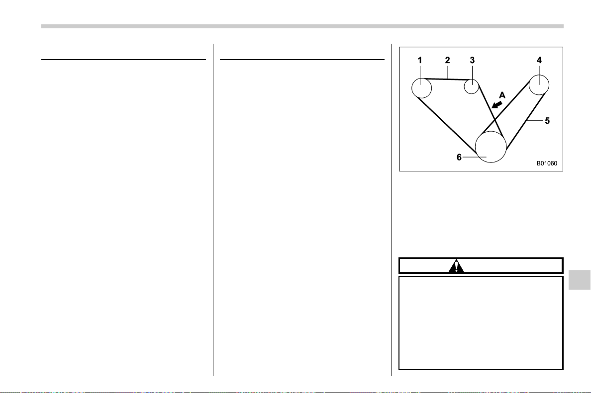
(519,1)
北米Model "A1700BE-B" EDITED: 2017/ 10/ 11
Spark plugs
It may be difficult to replace the spark
plugs. It is recommended that you have the
spark plugs replaced by your SUBARU
dealer.
Have the spark plugs replaced according
to the maintenance schedule in the “War-
ranty and Maintenance Booklet”.
& Recommended spark plugs
For the recommended spark plugs, refer to
“Electrical system” F12-8.
Drive belts
NOTE
For models except STI, it is unneces-
sary to check the deflection of the drive
belt periodically because this engine is
equipped with an automatic belt ten-
sion adjuster. However, have the belt
replaced according to the maintenance
schedule in the “Warranty and Main-
tenance Booklet” . Consult your
SUBARU dealer for replacement.
If the drive belt is loose, cracked or
worn, contact your SUBARU dealer.
STI
1) Power steering oil pump pulley
2) Front side belt
3) Alternator pulley
4) Air conditioner compressor pulley
5) Rear side belt
6) Crank pulley
A) 22 lbf (98 N, 10 kgf)
CAUTION
The front side belt, which runs in
conjunction with the following com-
ponents, must be used within the
specified deflection.
. Power steering oil pump pulley
. Alternator pulley
. Crank pulley
Check the deflection of the front side
– CONTINUED –
Maintenance and service/Spark plugs
11-21
11
(520,1)
北米Model "A1700BE-B" EDITED: 2017/ 10/ 11
belt and if there is any looseness,
cracks, wear or unusual noise on the
front side belt, contact your
SUBARU dealer.
Continuing to use the vehicle with
the belt outside of the specification
may cause the engine to malfunc-
tion and the above components to
malfunction.
To check the deflection of the front side
belt, place a straightedge (ruler) across
two adjacent pulleys (alternator pulley and
crank pulley) and apply a force of 22 lbf (98
N, 10 kgf) midway between the pulleys by
using a spring scale. The belt deflection
should be the amount specified. If the front
side belt is loose, cracked or worn, contact
your SUBARU dealer.
in (mm)
Deflection
New belt
Used belt
A
0.28 – 0.35
(7.0 – 9.0)
0.35 – 0.43
(9.0 – 11.0)
The rear side belt is a stretch-type belt,
therefore the deflection does not need to
be checked. If there are cracks or wear
confirmed on the belts and a squeaking
noise is heard from them, contact your
SUBARU dealer.
Manual transmission oil
It is not necessary to check the transmis-
sion oil level. Check that there are no
cracks, damage or leakage. However,
have the oil inspected by your SUBARU
dealer according to the maintenance
schedule in the “Warranty and Mainte-
nance Booklet”. Consult your SUBARU
dealer for details.
& Recommended grade and
viscosity
Each oil manufacturer has its own base
oils and additives. Never use different
brands together. For details, refer to
“Manual transmission, front differential
and rear differential gear oil” F12-6.
Continuously variable trans-
mission fluid
It is not necessary to check the transmis-
sion fluid level. Check that there are no
cracks, dam ag e or leakage . How eve r,
have the fluid inspected by your SUBARU
dealer according to the maintenance
schedule in the “Warranty and Mainte-
nance Booklet”. Consult your SUBARU
dealer for details.
Maintenance and service/Manual transmission oil
11-22
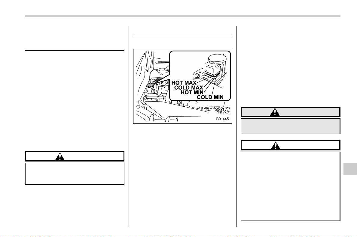
(521,1)
北米Model "A1700BE-B" EDITED: 2017/ 10/ 11
Front differential gear oil
(CVT models) and rear differ-
ential gear oil
It is not necessary to check the gear oil
level. Check that there are no cracks,
damage or leakage. However, have the oil
inspected by your SUBARU dealer ac-
cording to the maintenance schedule in
the “Warranty and Maintenance Booklet”.
Consult your SUBARU dealer for details.
& Recommended grade and
viscosity
Each oil manufacturer has its own base
oils and additives. Never use different
brands together. For details, refer to
“Manual transmission, front differential
and rear differential gear oil” F12-6.
CAUTION
Using a differential gear oil other
than the specified oil may cause a
decline in vehicle performance.
Power steering fluid (STI)
& Checking the fluid level
The power steering fluid expands greatly
as its temperature rises; the fluid level
differs according to fluid temperature.
Therefore, the reservoir tank has two
different checking ranges for hot and cold
fluids.
Check the po wer steeri ng fluid lev el
monthly.
1. Park the vehicle on a level surface, and
stop the engine.
2. Check the fluid level of the reservoir
tank.
When the fluid is hot after the vehicle has
been run: Check that the oi l level is
between “HOT MIN” and “HOT MAX” on
the surface of the reservoir tank.
When the fluid is cool before the vehicle is
run: Check that the oil level is between
“COLD MIN” and “COLD MAX” on the
surface of the reservoir tank.
3. If the fl uid level is lower than the
applicable “MI N” line , add the recom-
mended fluid as necessary to bring the
level between the “ MIN ” and “MAX” line.
If the fluid level is extremely low, it may
indicate possible leakage. Consult your
SUBARU dealer for an inspection.
WARNING
Be careful not to burn yourself
because the fluid may be hot.
CAUTION
. When you add power steering
fluid, use only clean fluid, and
be careful not to allow any dirt
into the tank. And never use
different brands together.
. Be careful not to spill power
steering fluid when adding it. If
power steering fluid touches the
exhaust pipe, it may cause a bad
smell, smoke, and/or a fire. If
power steering fluid gets on the
– CONTINUED –
Maintenance and service/Front differential gear oil (CVT models) and rear differential gear oil
11-23
11
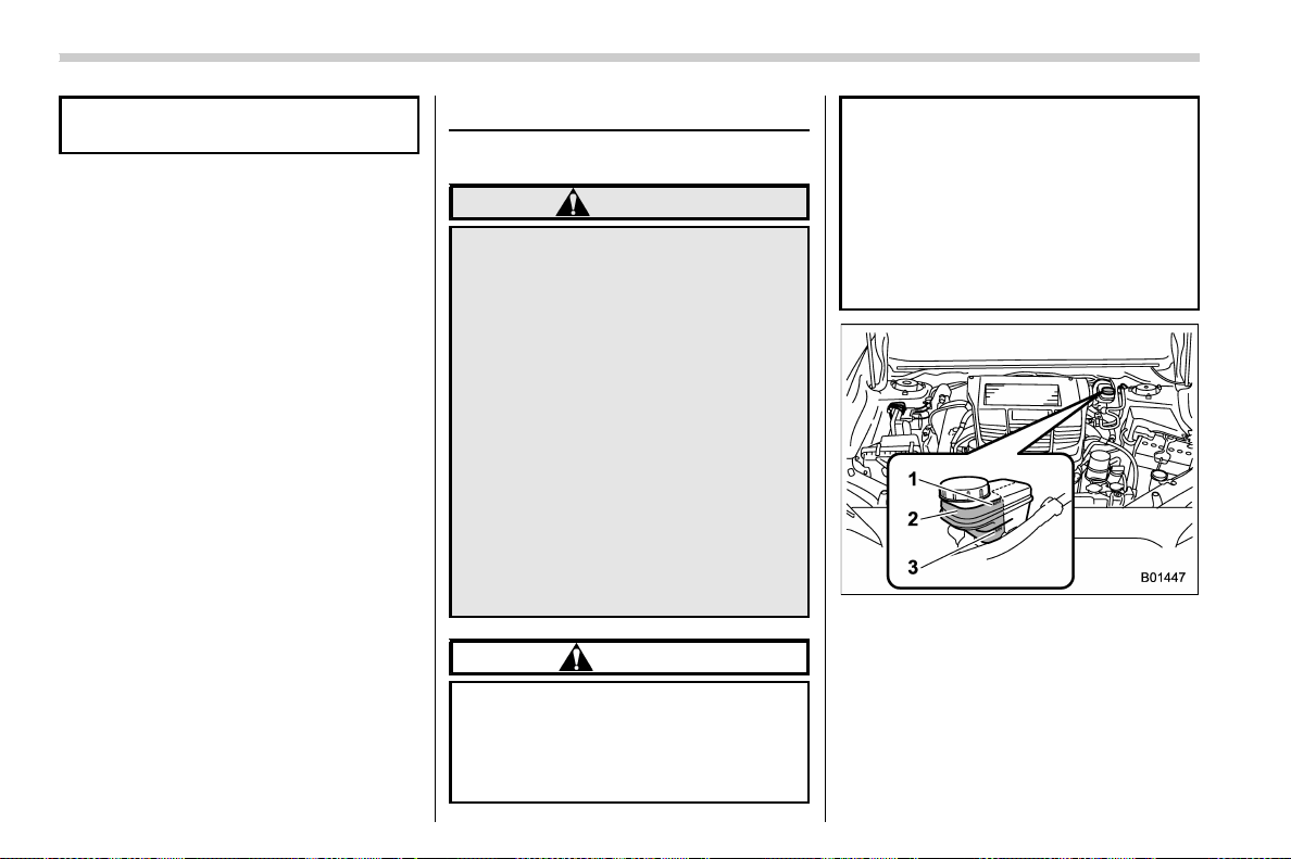
(522,1)
北米Model "A1700BE-B" EDITED: 2017/ 10/ 11
exhaust pipe, be sure to wipe it
off.
& Recommended fluid
Refer to “Fluids” F 12-7.
Brake fluid
& Checking the fluid level
WARNING
. Never let brake fluid contact your
eyes because brake fluid can be
harmful to your eyes. If brake
fluid gets in your eyes, immedi-
ately flush them thoroughly with
clean water. For safety, when
performing this work, wearin g
eye protection is advisable.
. Brake fluid absorbs moisture
from the air. Any absorbed moist-
ure can cause a dangerous loss
of braking performance.
. If the vehicle requires frequent
refilling, there may be a leak. If
you suspect a problem, have the
vehicle checked at your SUBARU
dealer.
CAUTION
. When adding brake fluid, be care-
ful not to allow any dirt into the
reservoir.
. Never splash the brake fluid over
painted surfaces or rubber parts.
Alcohol contained in the brake
fluid may damage them.
. Be careful not to spill brake fluid
when adding it. If brake fluid
touches the exhaust pipe, it may
cause a bad smell, smoke, and/or
a fire. If brake fluid gets on the
exhaust pipe, be sure to wipe it
off.
1) “MAX” level line
2) Check the brake fluid level in this area.
3) “MIN” level line
Check the fluid level monthly.
Check the fluid level on the outside of the
reservoir. Because this reservoir is used
for both the brake and clutch systems and
has chambers for each system, be sure to
check the fluid level for the brake system at
Maintenance and service/Brake fluid
11-24
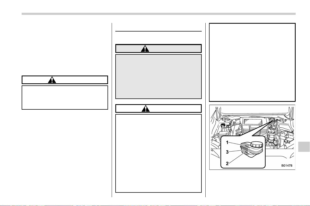
(523,1)
北米Model "A1700BE-B" EDITED: 2017/ 10/ 11
the front part of the reservoir (shaded
area in the illustration). If the fluid level is
below “MIN ”, add the recommended brake
fluid to “MAX”.
Use only brake fluid from a sealed contain-
er.
& Recommended brake fluid
Refer to “Fluids” F 12-7.
CAUTION
Never use different brands of brake
fluid together. Also, avoid mixing
DOT 3 and DOT 4 brake fluids even if
they are the same brand.
Clutch fluid (MT models)
& Checking the fluid level
WARNING
Never let clutch fluid contact your
eyes because clutch fluid can be
harmful to your eyes. If clutch fluid
gets in your eyes, immediately flush
them thoroughly with clean water.
For safety, when performing this
work, wearing eye protection is
advisable.
CAUTION
. Clutch fluid abso rbs moisture
from the air. Any absorbed moist-
ure can cause improper clutch
operation.
. If the vehicle requires frequent
refilling, there may be a leak. If
you suspect a problem, have the
vehicle checked at your SUBARU
dealer.
. When you add clutch fluid, be
careful not to allow any dirt into
the tank.
. Never splash the clutch fluid over
painted surfaces or rubber parts.
Alcohol contained in the clutch
fluid may damage them.
. Be careful not to spill clutch fluid
when adding it. If clu tch fluid
touches the exhaust pipe, it may
cause a bad smell, smoke, and/or
a fire. If clutch fluid gets on the
exhaust pipe, be sure to wipe it
off.
. Check the fluid level for the clutch
system at the inboard side of the
reservoir. You cannot check the
fluid level at the outboard side of
the reservoir.
1) “MAX” level line
2) Check the clutch fluid level in this area.
3) “MIN” level line
Check the fluid level monthly.
– CONTINUED –
Maintenance and service/Clutch fluid (MT models)
11-25
11
(524,1)
北米Model "A1700BE-B" EDITED: 2017/ 10/ 11
Check the fluid level on the outside of the
reservoir. Because this reservoir is used
for both the brake and clutch systems and
has chambers for each system, be sure to
check the fluid level for the clutch system
at the inboard side of the reservoir
(shaded area in the illustration). If the fluid
level is bel ow “MIN”, add the recom-
mended clutch fluid to “MAX”.
Use only clutch fluid from a sealed contain-
er.
& Recommended clutch fluid
Refer to “Fluids” F 12-7.
CAUTION
Never use different brands of clutch
fluid together. Also, avoid mixing
DOT 3 and DOT 4 brake fluids even if
they are the same brand.
Brake booster
If the brake booster does not operate as
described in the following, have it checked
by your SUBARU dealer.
1. With the engine off, depress the brake
pedal several times, applying the same
pedal force each time. The distance the
pedal travels should not vary.
2. With the brake pedal depressed, start
the engine. The pedal should move slightly
down to the floor.
3. With the brake pedal depressed, stop
the engine and keep the pedal depressed
for 30 seconds. The pedal height should
not change.
4. Start the engine again and run for
approximately one minute then turn it off.
Depress the brake pedal several times to
check the brake booster. The brake
booster operates properly if the pedal
stroke decreases with each depression.
NOTE
When you depress the brake pedal
strongly or suddenly, you might feel
that lighter depression of the brake
pedal generates a greater braki ng
force. However, even though these
occur, they do not indicate any mal-
functions, and the brake assist system
is operating properly.
Brake assist is not a system that brings
more braking ability to the vehicle
beyond its breaking capability.
Maintenance and service/Brake booster
11-26

(525,1)
北米Model "A1700BE-B" EDITED: 2017/ 10/ 11
Brake pedal
Check the brake pedal free play and
reserve distance according to the main-
tenance schedule in the “Warranty and
Maintenance Booklet”.
& Checking the brake pedal free
play
1) 0.02 – 0.11 in (0.5 – 2.7 mm)
Stop the engine and firmly depress the
brake pedal several times. Lightly pull the
brake pedal up with one finger to check the
free play with a force of less than 2 lbf (10
N, 1 kgf).
If the free play is not within proper
specification, contact your SUBARU deal-
er.
& Checking the brake pedal re-
serve distance
1) More than 2.56 in (65 mm)
Depress the pedal with a force of approxi-
mately 66 lbf (294 N, 30 kgf) and measure
the distance between the upper surface of
the pedal pad and the floor.
When the measurement is smaller than
the specification, or when the pedal does
not operate smoothly, contact with your
SUBARU dealer.
Clutch pedal (MT models)
Check the clutch pedal free play according
to the maintenance schedule in the “War-
ranty and Maintenance Booklet”.
& Checking the clutch function
Check the clutch engagement and disen-
gagement.
1. With the engine idling, check that there
are no abnormal noises when the clutch
pedal is depressed, and that shifting into
1st or reverse feels smooth.
2. Start the vehicle by releasing the pedal
slowly to check that the engine and
transmission smoothly couple without
any sign of slippage.
– CONTINUED –
Maintenance and service/Brake pedal
11-27
11
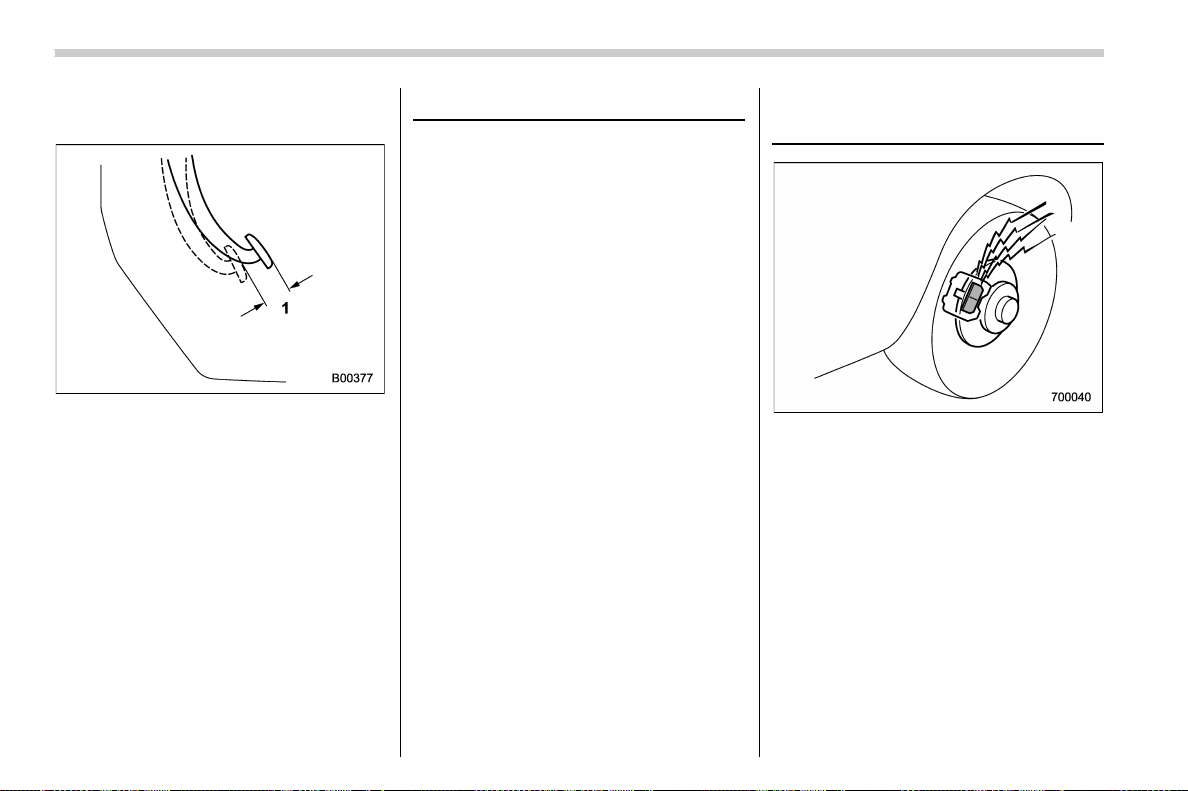
(526,1)
北米Model "A1700BE-B" EDITED: 2017/ 10/ 11
& Checking the clutch pedal
free play
1) 0.16 – 0.43 in (4.0 – 11.0 mm)
Lightly depress the clutch pedal down with
your finger until you feel resistance, and
check the free play.
If the free play is not within proper
specification, contact your SUBARU deal-
er.
Hill start assist system
Ensure that the Hill start assist system
operates properly under the following
circumstances.
1. Stop the vehicle on an uphill grade by
depressing the brake pedal (all models)
and clutch pedal (MT models only), with
the engine running.
2. Make sure that the vehicle does not
move backward for several seconds after
the brake pedal is released.
3. Then make sure the vehicle starts
climbing the grade by following the normal
starting procedures.
If the Hill start assist system does not
operate as described above, contact your
SUBARU dealer.
Replacement of brake pad
and lining
The disc brakes have audible wear in-
dicators on the brake pads. If the brake
pads wear close to their service limit, the
wear indicator makes a very audible
scraping noise when the brake pedal is
applied.
If you hear this scraping noise each time
you apply the brake pedal, have the brake
pads serviced by your SUBARU dealer as
soon as possible.
Maintenance and service/Hill start assist system
11-28

(527,1)
北米Model "A1700BE-B" EDITED: 2017/ 10/ 11
CAUTION
. It is recommended that you dis-
connect the vehicle battery be-
fore replacing the brake pad.
However, it is dangerous to dis-
connect the vehicle battery. We
recommend that you have your
SUBARU dealer replace the brake
pad.
. If you continue to drive despite
the scraping noise from the audi-
ble brake pad wear indicator, it
will result in the need for costly
brake rotor repair or replace-
ment.
& Breaking-in of new brake
pads (models with electronic
parking brake system)
When replacing the brake pad, use only
genuine SUBARU parts. After replace-
ment, break in the new parts as follows.
! Brake pad
While maintaining a speed of 30 to 40 mph
(50 to 65 km/h), step on the brake pedal
lightly. Repeat this five or more times. Also,
apply and release the electronic parking
brake five or more times.
& Breaking-in of new brake
pads and linings (models
without electronic parking
brake system)
When replacing the brake pad or lining,
use only genuine SUBARU parts. After
replacement, break in the new parts as
follows.
! Brake pad and lining
While maintaining a speed of 30 to 40 mph
(50 to 65 km/h), step on the brake pedal
lightly. Repeat this five or more times.
! Parking brake lining
1. Drive the vehicle at a speed of approxi-
mately 22 mph (35 km/h).
2. With the parking brake release button
pushed in, pull the parking brake lever
SLOWLY and GENTLY (pulling with a
force of approximately 33.7 lbf [150 N,
15.3 kgf]).
3. Drive the vehicle for approximately 220
yards (200 meters) in this condition.
4. Wait 5 to 10 minutes for the parking
brake to cool down. Repeat this proce-
dure.
5. Check the parking brake stroke. If the
parking brake stroke is out of the specified
range, adjust it by turning the adjusting nut
located on the parking brake lever.
Parking brake stroke:
7 – 8 notches / 45 lbf (200 N, 20.4 kgf)
WARNING
Select a safe location and situation
for break-in driving.
CAUTION
Pulling the parking brake lever too
forcefully may cause the rear wheels
to lock. To avoid this, be certain to
pull the lever up slowly and gently.
Maintenance and service/Replacement of brake pad and lining
11-29
11
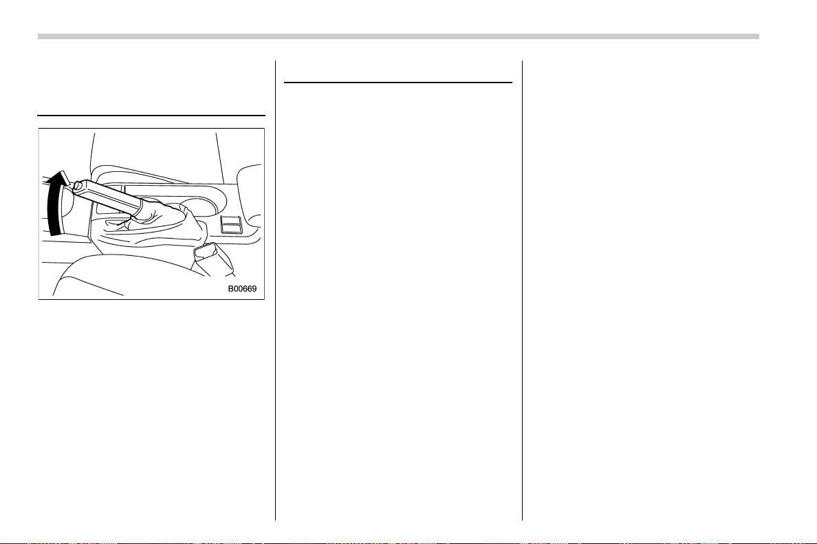
(528,1)
北米Model "A1700BE-B" EDITED: 2017/ 10/ 11
Parking brake stroke (models
without electronic parking
brake system)
Check the parking brake stroke according
to the maintenance schedule in the “War-
ranty and Maintenance Booklet”.
When the parking brake is properly ad-
justed, braking power is fully applied by
pulling the lever up 7 to 8 notches gently
but firmly (approximately 45 lbf [200 N,
20.4 kgf]). If the parking brake lever stroke
is not within the specified range, have the
brake system checked and adjusted at
your SUBARU dealer.
Tires and wheels
& Types of tires
You should be familiar with type of tires
present on your vehicle.
! All season tires
All season tires are designed to provide an
adequate measure of traction, handling
and braking performance in year-round
driving including snowy and icy road
conditions. However all season tires do
not offer as much traction performance as
winter (snow) tires in heavy or loose snow
or on icy roads.
All season tires are identified by “ALL
SEASON” and/or “M+S” (Mud & Snow) on
the tire sidewall.
! Summer tires
Summer tires are high-speed capability
tires best suited for highway driving under
dry conditions.
Summer tires are inadequate for driving on
slippery roads such as on snow-covered or
icy roads.
If you drive your vehicle on snow-covered
or icy roads, we strongly recommend the
use of winter (snow) tires.
When installing winter tires, be sure to
replace all four tires.
! Winter (snow) tires
Winter tires are best suited for driving on
snow-covered and icy roads. However
winter tires do not perform as well as
summer tires and all season tires on roads
other than snow-covered and icy roads.
& Tire pressure monitoring
system (TPMS) (if equipped)
The tire pressure monitoring system pro-
vides the driver with a warning message by
sending a signal from a sensor that is
installed in each wheel when tire pressure
is severely low. The tire pressure monitor-
ing system will activate only when the
vehicle is driven. Also, this system may not
react immediately to a sudden drop in tire
pressure (for example, a blow-out caused
by running over a sharp object).
Maintenance and service/Parking brake stroke (models without electronic parking brake system)
11-30
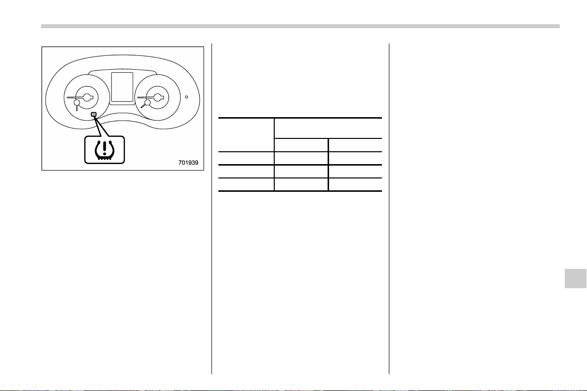
(529,1)
北米Model "A1700BE-B" EDITED: 2017/ 10/ 11
Low tire pressure warning light
If you adjust the tire pressures in a warm
garage and will then drive the vehicle in
cold outside air, the resulting drop in tire
pressures may cause the low tire pressure
warning light to illuminate. To avoid this
problem when adjusting the tire pressures
in a warm garage, inflate the tires to
pressures higher than those shown on
the tire placard. Specifically, inflate them
by an extra 1 psi (6.9 kPa, 0.07 kgf/cm
2
) for
every difference of 108F (5.68C) between
the temperature in the garage and the
temperature outside. By way of example,
the following table shows the required tire
pressures that correspond to various out-
side temperatures when the temperature
in the garage is 608F (15.68C).
Example:
Tire size: 245/40R18 97W
Standard tire pressures:
Front: 33 psi (230 kPa, 2.3 kgf/cm
2
)
Rear: 32 psi (220 kPa, 2.2 kgf/cm
2
)
Garage temperature: 608F (15.68C)
Outside
temperature
Adjusted pressure
[psi (kPa, kgf/cm
2
)]
Front Rear
308F(−18C) 36 (250, 2.5) 35 (240, 2.4)
108F(−128C) 38 (260, 2.6) 37 (255, 2.55)
−108F(−238C) 40 (275, 2.75)
39 (270, 2.7)
If the low tire pressure warning light
illuminates when you drive the vehicle in
cold outside air after adjusting the tire
pressures in a warm garage, re-adjust the
tire pressures using the method described
above. Then, increase the vehicle speed
to at least 20 mph (32 km/h) and check to
see that the low tire pressure warning light
turns off a few minutes later. If the low tire
pressure warning light does not turn off,
the tire pressure monitoring system may
not be functioning normally. In this event,
go to a SUBARU dealer to have the
system inspected as soon as possible.
While the vehicle is driven, friction be-
tween tires and the road surface causes
the tires to warm up. After illumination of
the low tire pressure warning light, any
increase in the tire pressures caused by an
increase in the outside air temperature or
by an increase in the temperature in the
tires can cause the low tire pressure
warning light to turn off.
System resetting is necessary when the
wheels are changed (for example, a switch
to snow tires) and new TPMS valves are
installed on the newly fitted wheels. Have
this work performed by a SUBARU dealer
following wheel replacement.
It may not be possible to install TPMS
valves on certain wheels that are on the
market. Therefore, if you change the
wheels (for example, a switch to snow
tires), use wheels that have the same part
number as the standard-equipment
wheels. Without four operational TPMS
valve/sensors on the wheels, the TPMS
will not fully function and the warning light
on the combination meter will illuminate
steadily after blinking for approximately
one minute.
When a tire is replaced, adjustments are
necessary to ensure continued normal
operation of the tire pressure monitoring
system. As with wheel replacement, there-
fore, you should have the work performed
by a SUBARU dealer.
– CONTINUED –
Maintenance and service/Tires and wheels
11-31
11
(530,1)
北米Model "A1700BE-B" EDITED: 2017/ 10/ 11
WARNING
If the low tire pressure warning light
does not illuminate briefly after the
ignition switch is turned ON or the
light illuminates steadily after blink-
ing for approximately one minute,
you should have your Tire Pressure
Monitoring System c hecked at a
SUBARU dealer as soon as possi-
ble.
If this light illuminates while driving,
never brake suddenly. Instead, per-
form the following procedure. Other-
wise an accident involving serious
vehicle damage and serious perso-
nal injury could occur.
1) Keep driving straight ahead while
gradually reducing speed.
2) Slowly pull off the road to a safe
place.
If this light still illuminates while
driving after adjusting the tire pres-
sure, a tire may have significant
damage and a fast leak that causes
the tire to lose air rapidly. If you have
a flat tire, refer to “Flat tires” F9-5.
When a spare tire is mounted or a
wheel rim is replaced without the
original pressure sensor/transmitter
being transferred, the low tire pres-
sure warning light will illuminate
steadily after blinking for approxi-
mately one minute. This indicates
the TPMS is unable to monitor all
four road wheels. Contact your
SUBARU dealer as soon as possible
for tire and sensor replacement and/
or system resetting. If the light
illuminates s teadily after blinking
for approximately one minute,
promptly contact a SUBARU dealer
to have the system inspected.
& Tire inspection
Check on a daily basis that the tires are
free from serious damage, nails, and
stones. At the same time, check the tires
for abnormal wear.
Contact your SUBARU dealer immediately
if you find any problem.
NOTE
. When the wheels and tires strike
curbs or are subjected to harsh treat-
ment as when the vehicle is driven on a
rough surface, they can suffer damage
that cannot be seen with the naked eye.
This type of damage does not become
evident until time has passed. Try not to
drive over curbs, potholes or on other
rough surfaces. If doing so is unavoid-
able, keep the vehicle’s speed down to
a walking pace or less, and approach
the curbs as squarely as possible. Also,
make sure the tires are not pressed
against the curb when you park the
vehicle.
. If you feel unusual vibration while
driving or find it difficult to steer the
vehicle in a straight line, one of the tires
and/or wheels may be damaged. Drive
slowly to the nearest authorized
SUBARU dealer and have the vehicle
inspected.
& Tire pressures and wear
Maintaining the correct tire pressures
helps to maximize the tires’ service lives
and is essential for good running perfor-
mance. Check and, if necessary, adjust
the pressure of each tire (including the
spare) at least once a month (for example,
during a fuel stop) and before any long
journey.
Maintenance and service/Tires and wheels
11-32
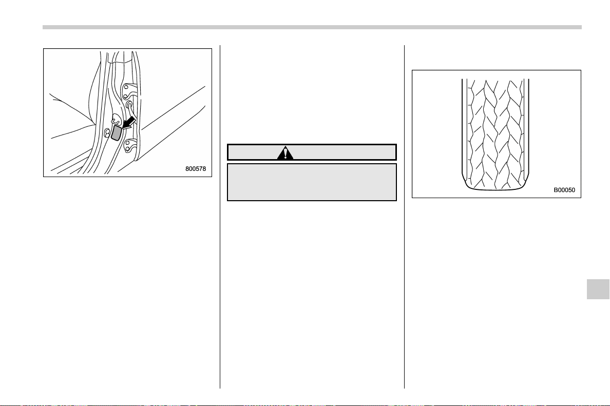
(531,1)
北米Model "A1700BE-B" EDITED: 2017/ 10/ 11
Tire placard
Check the tire pressures when the tires are
cold. Use a pressure gauge to adjust the
tire pressures to the values shown on the
tire placard. The tire placard is located on
the door pillar on the driver’s side.
Driving even a short distance warms up
the tires and increases the tire pressures.
Also, the tire pressures are affected by the
outside temperature. It is best to check tire
pressure outdoors before driving the ve-
hicle.
When a tire becomes warm, the air inside it
expands, causing the tire pressure to
increase. Be careful not to mistakenly
release air from a warm tire to reduce its
pressure.
NOTE
. The air pressure in a tire increases
by approximately 4.3 psi (30 kPa, 0.3
kgf/cm
2
) when the tire becomes warm.
. The tires are considered cold when
you have parked the vehicle for at least
three hours or have driven less than
one mile (1.6 km).
WARNING
Do not let air out of warm tires to
adjust pressure. Doing so will result
in low tire pressure.
Incorrect tire pressures detract from con-
trollability and ride comfort, and they cause
the tires to wear abnormally.
. Correct tire pressure (tread worn
evenly)
Roadholding is good, and steering is
responsive. Rolling resistance is low, so
fuel consumption is also lower.
– CONTINUED –
Maintenance and service/Tires and wheels
11-33
11
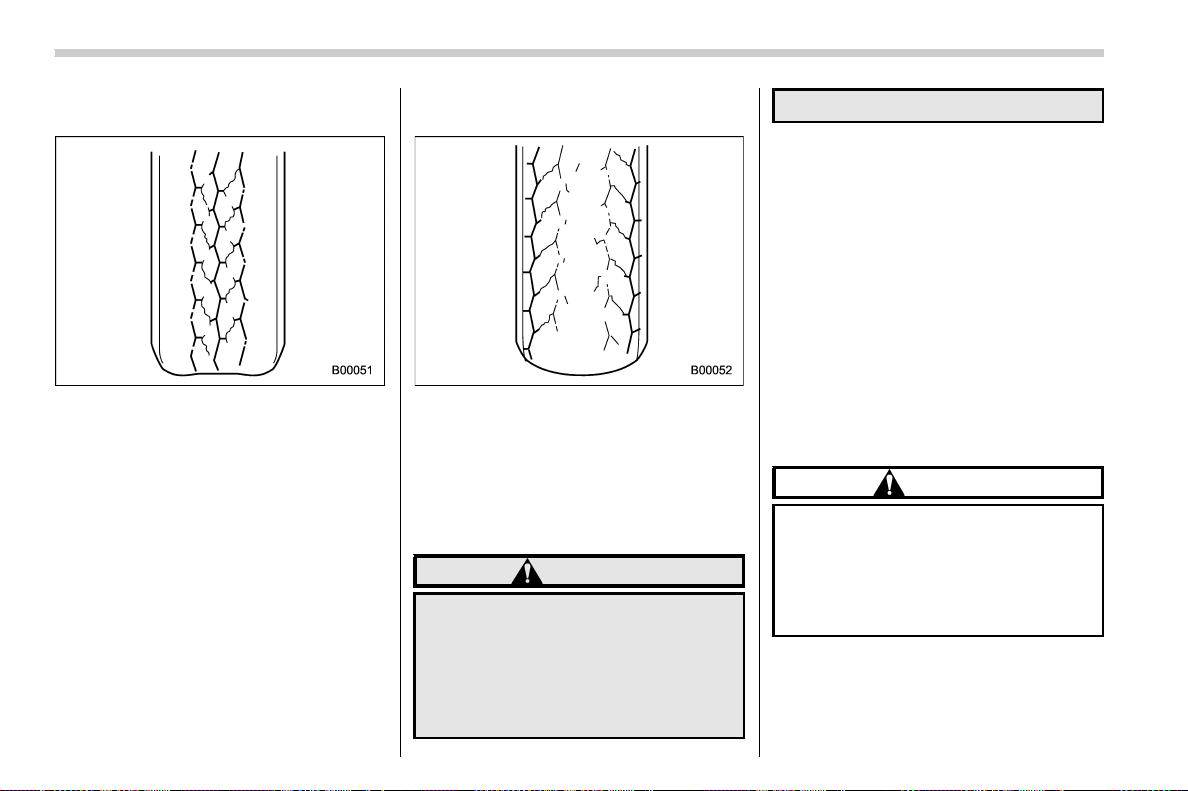
(532,1)
北米Model "A1700BE-B" EDITED: 2017/ 10/ 11
. Under infl ated tire (tread worn on
shoulders)
Rolling resistance is high, so fuel con-
sumption is also higher.
. Over inflated tire (tread worn in the
center)
Ride comfort is poor. Also, the tire magni-
fies the effects of road-surface bumps and
dips, possibly resulting in vehicle damage.
If the tire placard shows tire pressures for
the vehicle when fully loaded, adjust the
tire pressures to the values that match the
loading conditions.
WARNING
Driving at high speeds with exces-
sively low tire pressures can cause
the tires to deform severely and to
rapidly heat up. A sharp increase in
temperature could cause tread se-
paration, and destruction of the
tires. The resulting loss of vehicle
control could lead to an accident.
& Wheel balance
Each wheel was correctly balanced when
your vehicle was new, but the wheels will
become unbalanced as the tires become
worn during use. Wheel imbalance causes
the steering wheel to vibrate slightly at
certain vehicle speeds and detracts from
the vehicle’s straight-line stability. It can
also cause steering and suspension sys-
tem problems and abnormal tire wear. If
you suspect that the wheels are not
correctly balanced, have them checked
and adjusted by your SUBARU dealer.
Also have them adjusted after tire repairs
and after tire rotation.
CAUTION
Loss of correct wheel alignment
causes the tires to wear on one side
and reduces the vehicle’s running
stability. Contact your SUBARU
dealer if you notice abnormal tire
wear.
Maintenance and service/Tires and wheels
11-34
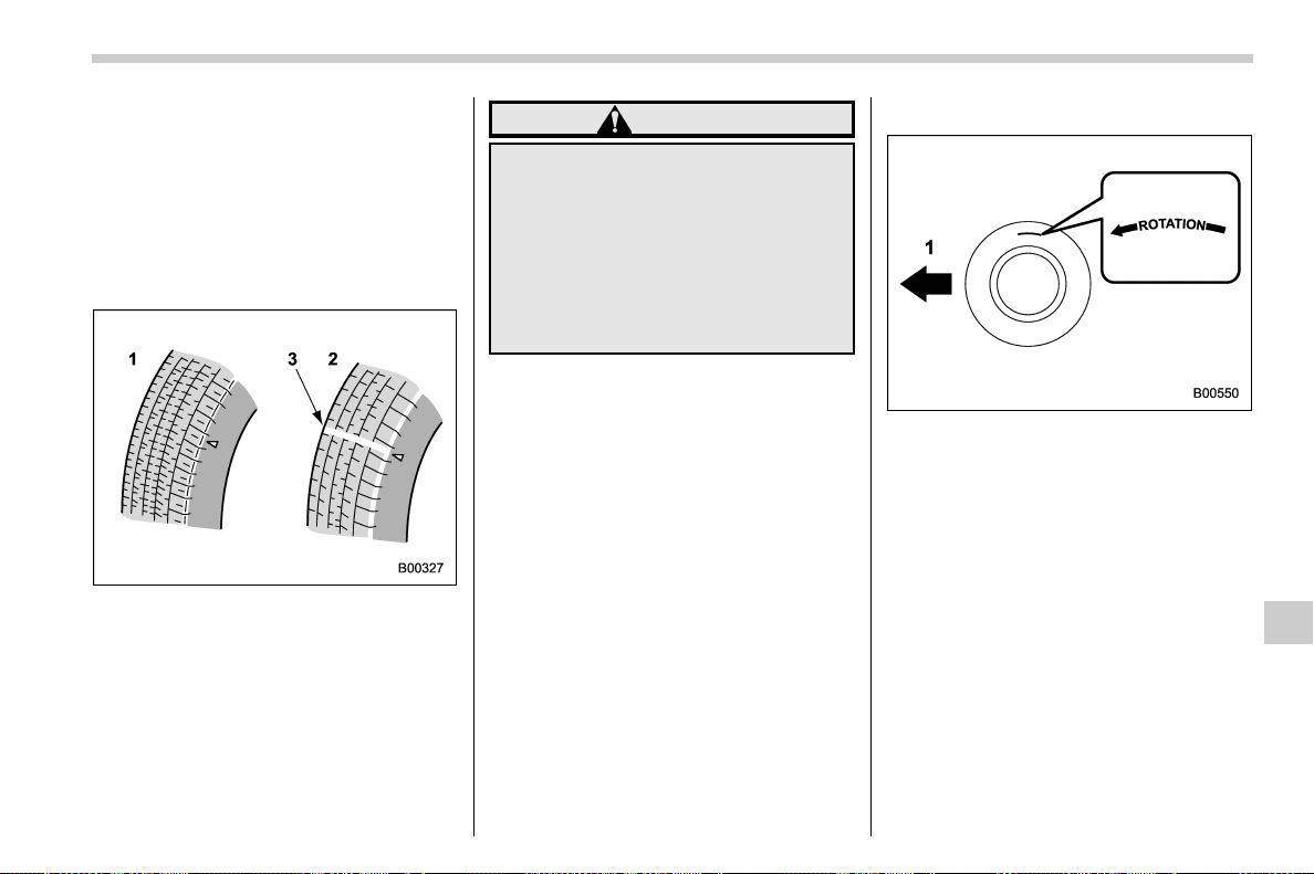
(533,1)
北米Model "A1700BE-B" EDITED: 2017/ 10/ 11
NOTE
The suspension system is designed to
hold each wheel at a certain alignment
(relative to the other wheels and to the
road) for optimum straight-line stability
and cornering performance.
& Wear indicators
1) New tread
2) Worn tread
3) Tread wear indicator
Each tire incorporates a tread wear in-
dicator, which becomes visible when the
depth of the tread grooves decreases to
0.063 in (1.6 mm). Replace the tire when
the tread wear indicator appears as a solid
band across the tread.
WARNING
When a tire’s tread wear indicator
becomes visible, the tire is worn
beyond the acceptable limit and you
must replace it immediately. With a
tire in this condition, driving at high
speeds in wet weather can cause the
vehicle to hydroplane. The resulting
loss of vehicle control can lead to an
accident.
NOTE
For safety, inspect tire tread regularly
and replace the tires before their tread
wear indicators become visible.
& Rotational direction of tires
Example of rotational direction marked on
the sidewall
1) Front
If the tires have specific rotational direc-
tion, refer to the arrow marked on the side
wall.
The a rrow should be pointing forward
when the wheels are fitted.
– CONTINUED –
Maintenance and service/Tires and wheels
11-35
11
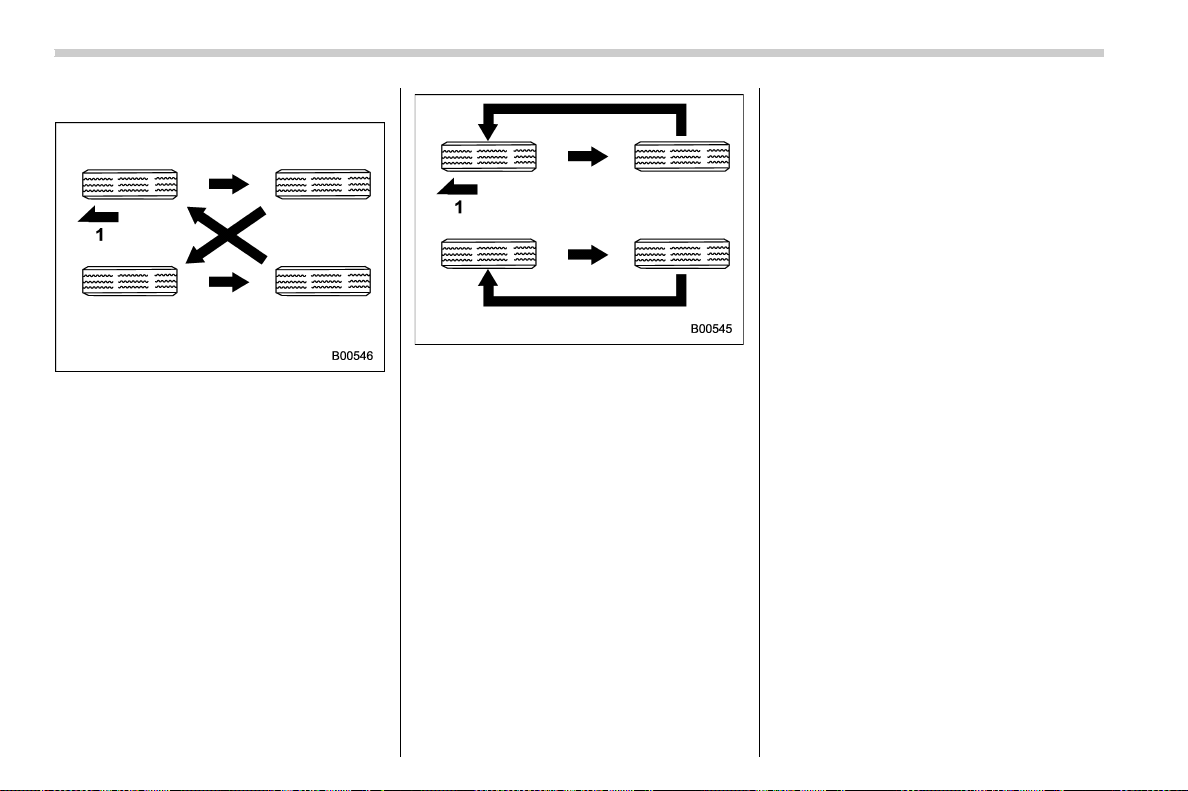
(534,1)
北米Model "A1700BE-B" EDITED: 2017/ 10/ 11
& Tire rotation
Vehicles equipped with 4 non-unidirec-
tional tires
1) Front
Vehicles equipped with unidirectional
tires
1) Front
Tire wear varies from wheel to wheel.
Move the tires to the positions shown in the
illustration each time they are rotated. For
the tire rotation schedule, refer to the
“Warranty and Maintenance Booklet ”.
Replace any damaged or unevenly worn
tires at the time of rotation. After tire
rotation, adjust the tires pressures and
make sure the wheel nuts are correctly
tightened.
After driving approximately 600 miles
(1,000 km), check the wheel nuts again
and retighten any nut that has become
loose.
& Tire replacement
The wheels and tires are important and
integral parts of your vehicle’s design; they
cannot be changed arbitrarily. The tires
fitted as standard equipment are optimally
matched to the characteristics of the
vehicle and were selected to give the best
possible combination of running perfor-
mance, ride comfort, and service life. It is
essential for every tire to have a size and
construction matching those shown on the
tire placard and to have a speed symbol
and load index matching those shown on
the tire placard.
Using tires of a non-specified size detracts
from controllability, ride comfort, braking
performance, speedometer accuracy and
odometer accuracy. It also creates incor-
rect body-to-tire clearances and inappro-
priately changes the vehicle’s ground
clearance.
All four tires must be the same in terms of
manufacturer, brand (tread pattern), con-
struction, and size. You are advised to
replace the tires with new ones that are
identical to those fitted as standard equip-
ment.
For safe vehicle operation, SUBARU
recommends replacing all four tires at the
same time.
Maintenance and service/Tires and wheels
11-36
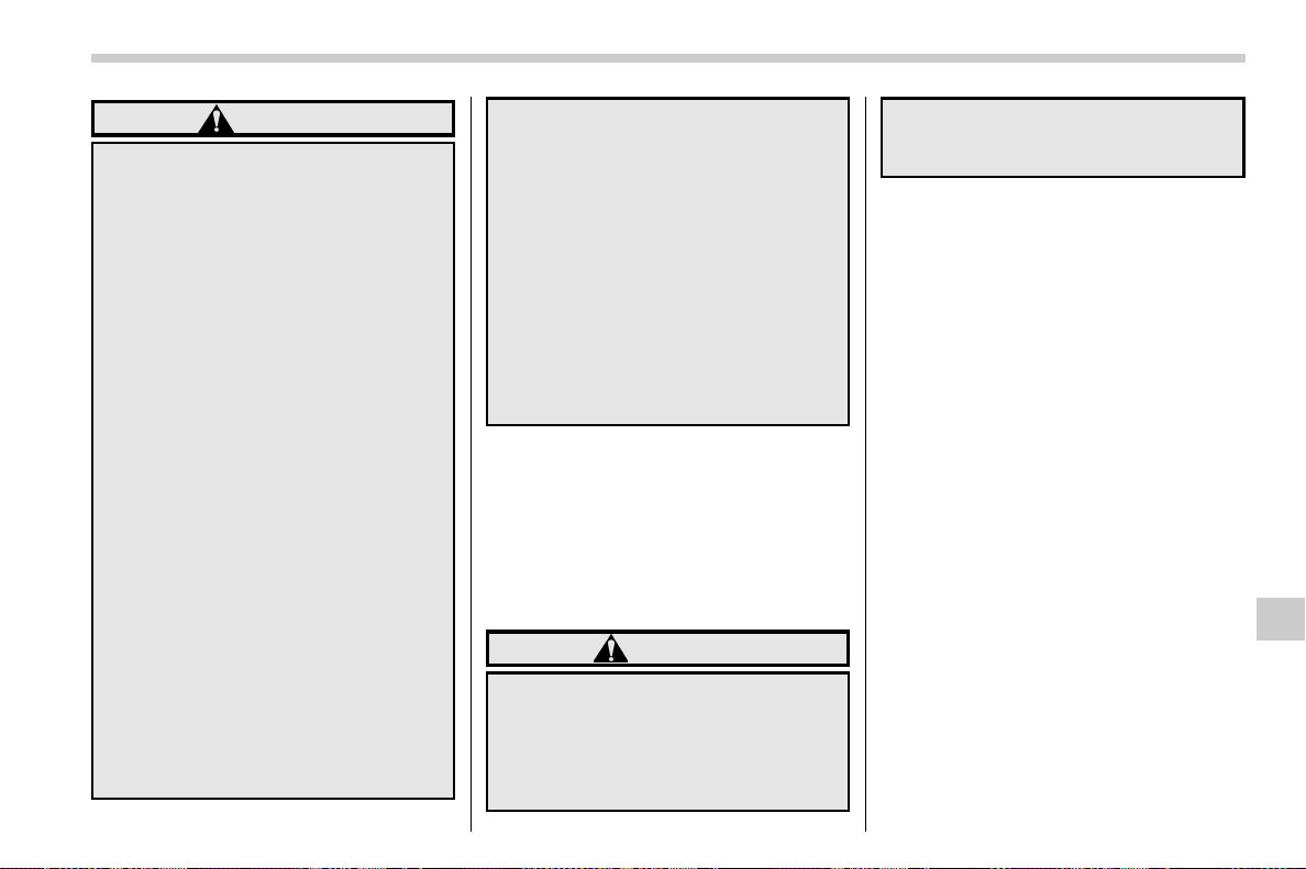
(535,1)
北米Model "A1700BE-B" EDITED: 2017/ 10/ 11
WARNING
. When replacing or installing
tire(s), all four tires must be the
same for the following items.
(a) Size
(b) Circumference
(c) Speed symbol
(d) Load index
(e) Construction
(f) Manufacturer
(g) Brand (tread pattern)
(h) Degrees of wear
For items (a) to (d), you must
obey the specification that is
printed on the tire placard. The
tire placard is located on the
driver’s door pillar.
If all four tires are not the same in
items (a) to (h), there is a possi-
bility that it may lead to serious
mechanical damage to the drive
train of your car and affect the
following factors.
— Ride
— Handling
— Braking
— Speedometer/Odometer
calibration
— Clearance between the body
and the tires
It also may be dangerous and
lead to loss of vehicle control,
and it can lead to an accident.
. Use only radial tires. Do not use
radial tires together with belted
bias tires and/or bias-ply tires.
Doing so can dangerously re-
duce controllability, resulting in
an accident.
& Wheel replacement
When replacing wheels due, for example,
to damage, make sure the replacement
wheels match the specifications of the
wheels that are fitted as standard equip-
ment. Replacement wheels are available
from SUBARU dealers.
WARNING
Use only those wheels that are
specified for your vehicle. Wheels
not meeting specifications could
interfere with brake caliper opera-
tion and may cause the tires to rub
against the wheel well housing dur-
ing turns. The resulting loss of
vehicle control could lead to an
accident.
NOTE
When any of the wheels are removed
and replaced for tire rotation or to
change a flat tire, always check the
tightness of the wheel nuts after driving
approximately 600 miles (1,000 km). If
any nut is loose, tighten it to the
specified torque.
Maintenance and service/Tires and wheels
11-37
11
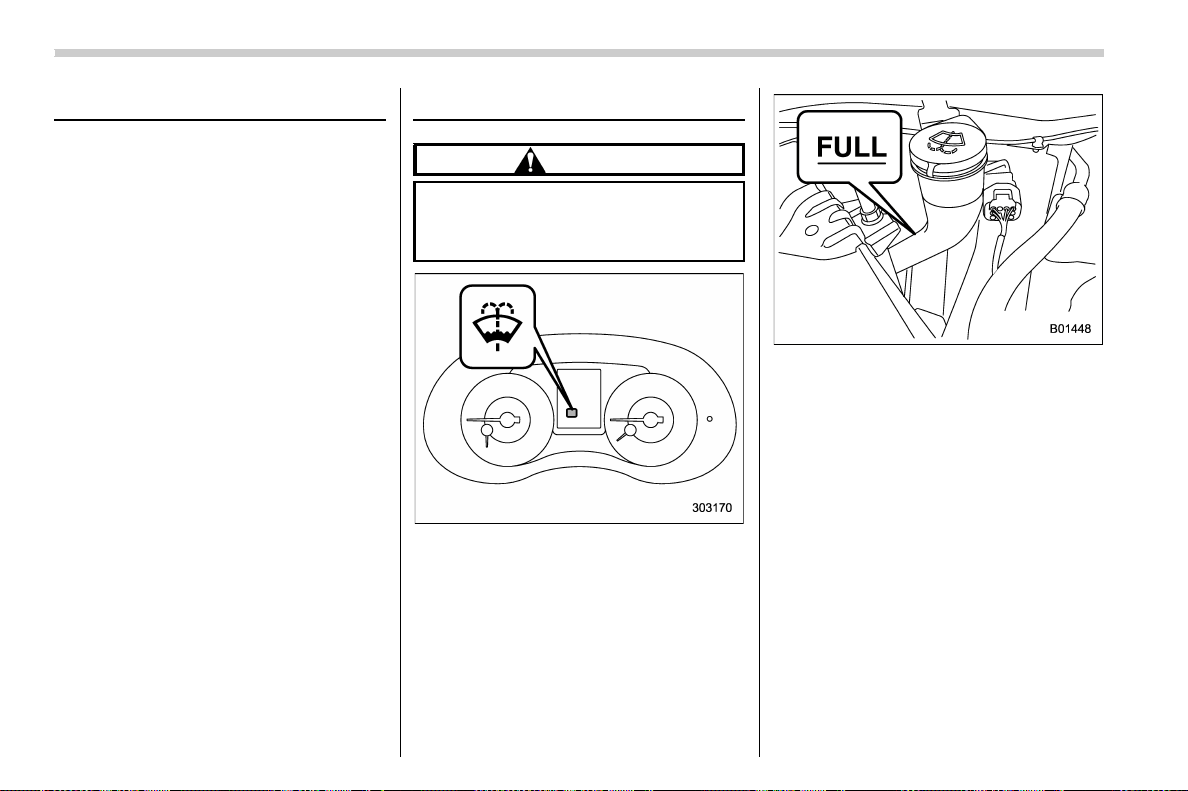
(536,1)
北米Model "A1700BE-B" EDITED: 2017/ 10/ 11
Alloy wheels
Alloy wheels can be scratched and da-
maged easily. Handle them carefully to
maintain their appearance, performance,
and safety.
. When any of the wheels are removed
and replaced for tire rotation or to change a
flat tire, always check the tightness of the
wheel nuts after driving approximately 600
miles (1,000 km). If any nut is loose,
tighten it to the specified torque.
. Never apply oil to the threaded parts,
wheel nuts, or tapered surface of the
wheel.
. Never let the wheel rub against sharp
protrusions or curbs.
. When wheel nuts, balance weights, or
the center cap is replaced, be sure to
replace them with genuine SUBARU parts
designed for alloy wheels.
Windshield washer fluid
CAUTION
Never use engine coolant as washer
fluid because it could cause paint
damage.
Windshield washer fluid warning in-
dicator
When there is only a small amount of
washer fluid re maining, the windshield
washer fluid warning indicator will illumi-
nate. When this occurs, refill the washer
fluid as follows.
Remove the washer tank filler cap, then
add windshield washer fluid until it reaches
the “FULL” mark on the tank. If windshield
washer fluid is unavailable use clean
water.
In areas where water freezes in winter, use
an anti-freeze type windshield washer
fluid. SUBARU Windshield Washer Fluid
contains 58.5% methyl alcohol and 41.5%
surfactant, by volume. Its freezing tem-
perature varies according to how much it is
diluted, as indicated in the following table.
Maintenance and service/Alloy wheels
11-38
(537,1)
北米Model "A1700BE-B" EDITED: 2017/ 10/ 11
Washer Fluid
Concentration
Freezing
Temperature
30%
10.48F(−128C)
50% −48F(−208C)
100% −498F(−458C)
In order to prevent freezing of washer fluid,
check the freezing temperatures in the
table above when adjusting the fluid
concentration to the outside temperature.
If you fill the reservoir tank with a fluid with
a different concentration from the one
used previously, purge the old fluid from
the piping between the reservoir tank and
washer nozzles by operating the washer
for a certain period of time. Otherwise, if
the concentration of the fluid remaining in
the piping is too low for the outside
temperature, it may freeze and block the
nozzles.
CAUTION
. Adjust the washer fluid concen-
tration appropriately for the out-
side temperature. If the concen-
tration is inappropriate, sprayed
washer fluid may freeze on the
windshield and obstruct your
view, and the fluid may freeze in
the reservoir tank.
. State or local regulations on
volatile organic compounds may
restrict the use of methanol, a
common windshield washer anti-
freeze additive. Use washer fluids
containing non-methanol anti-
freeze agents only if they provide
cold weather protection without
damaging your vehic le ’s paint,
wiper blades or washer system.
Replacement of wiper blades
Grease, wax, insects, or other material on
the windshield or the wiper blade results in
jerky wiper operation and streaking on the
glass. If you cannot remove the streaks
after operating the windshield washer or if
the wiper operation is jerky, clean the outer
surface of the windshield and the wiper
blades using a sponge or soft cloth with a
neutral detergent or mild-abrasive cleaner.
After cleaning, rinse the windshield and
wiper blades with clean water. The wind-
shield is clean if beads do not form when
you rinse the windshield with water.
CAUTION
. Do not clean the wiper blades
with gasoline or a solvent, such
as paint thinner or benzine. This
will cause deteriorati on of the
wiper blades.
. When you are going to raise the
passenger-side wiper arm, first
raise the driver-side wiper arm.
Otherwise, the p assenger-side
wiper assembly and driver-side
wiper assembly will touch each
other, possibly resulting in
scratches.
. Return the passenger-side wiper
– CONTINUED –
Maintenance and service/Replacement of wiper blades
11-39
11
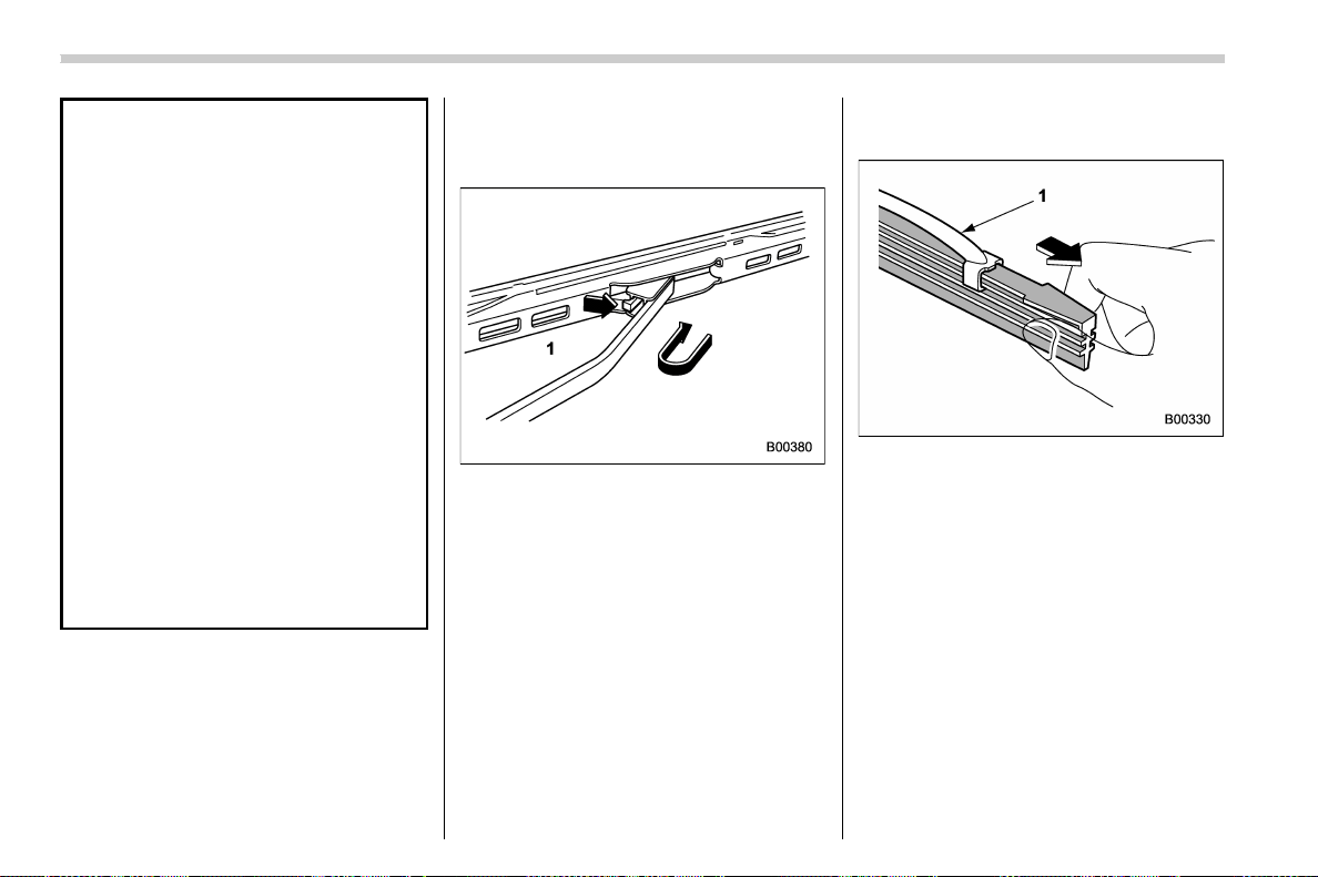
(538,1)
北米Model "A1700BE-B" EDITED: 2017/ 10/ 11
arm to its original position before
returning the driver-side wiper
arm to its original position. Other-
wise, the passenger-side wiper
assembly and driver-side wiper
assembly will touch each other,
possibly resulting in scratches.
. While removing the wiper blades
from the wiper arms, do not
return the wiper arms to the
original positions. Otherwise,
the windshield surface may be
scratched.
. When returning the raised wiper
arms to the original positions,
carefully return the wiper arms
on the windshield by hand. You
should not return the wiper arms
to the windshield only by the
return spring. Otherwise, the wi-
per arms may be deformed and/or
the windshield surface may be
scratched.
If you cannot eliminate the streaking even
after following this method, replace the
wiper blades using the following proce-
dures.
& Windshield wiper blade as-
sembly
1. Raise the wiper arm off the windshield.
1) Stopper
2. Remove the wiper blade assembly by
holding its pivot area and pushing it in the
direction shown by the arrow while depres-
sing the wiper blade stopper.
3. Install the wiper blade assembly to the
wiper arm. Make sure that it locks in place.
4. Hold the wiper arm by hand and slowly
lower it in position.
& Windshield wiper blade rub-
ber
1) Metal support
1. Grasp the locked end of the blade
rubber assembly and pull it firmly until the
stoppers on the rubber are free of the
metal support.
Maintenance and service/Replacement of wiper blades
11-40
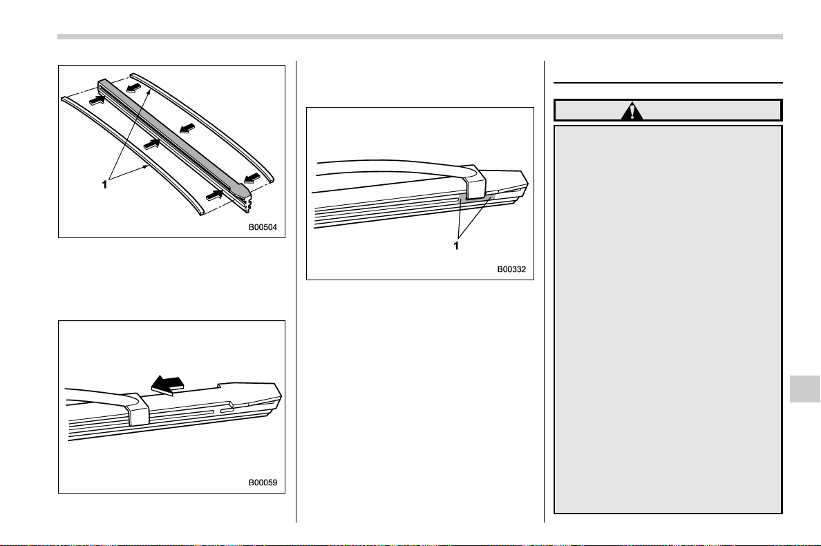
(539,1)
北米Model "A1700BE-B" EDITED: 2017/ 10/ 11
1) Metal spines
2. If the new blade rubber is not provided
with two metal spines, remove the metal
spines from the old blade rubber and install
them in the new blade rubber.
3. Align the claws of the metal support
with the grooves in the rubber and slide the
blade rubber assembly into the metal
support until it locks.
1) Stopper
4. Be sure to position the claws at the end
of the metal support between the stoppers
on the rubber as shown. If the rubber is not
retained properly, the wiper blade may
scratch the windshield.
Battery
WARNING
. Before beginning work on or near
any battery, be sure to extinguish
all cigarettes, matches, and light-
ers. Never expose a battery to an
open flame or electric sparks.
Batteries give off a gas which is
highly flammable and explosive.
. For safety, in case an explosion
does occur, wear eye protection
or shield your eyes when working
near any battery. Never lean over
a battery.
. Do not let battery fluid contact
eyes, skin, fabrics, or paint be-
cause battery fluid is a corrosive
acid. If battery fluid gets on your
skin or in your eyes, immediately
flush the area with water thor-
oughly. Seek medical help imme-
diately if acid has entered the
eyes.
If battery fluid is accidentally
swallowed, immediately drink a
large amount of milk or water,
and seek medical attention im-
mediately.
. To lessen the risk of sparks,
– CONTINUED –
Maintenance and service/Battery
11-41
11
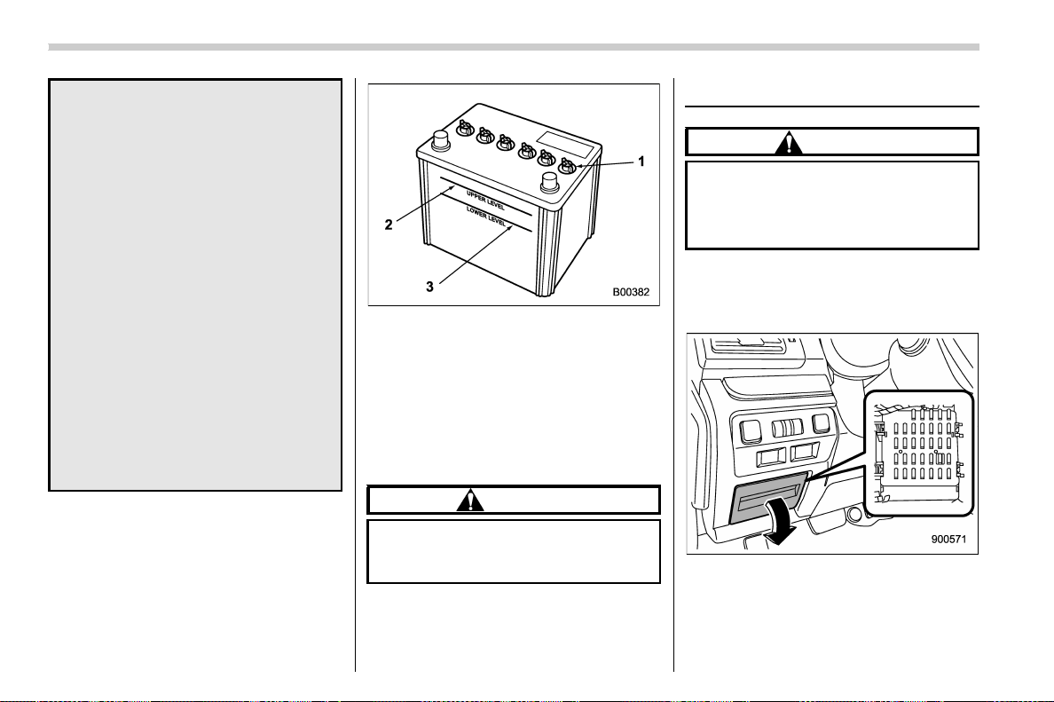
(540,1)
北米Model "A1700BE-B" EDITED: 2017/ 10/ 11
remove rings, metal watchbands,
and other metal jewelry. Never
allow metal tools to contact the
positive battery terminal and any-
thing connected to it WHILE you
are at the same time in contact
with any other metallic portion of
the vehicle because a short cir-
cuit will result.
. Keep everyone including children
away from the battery.
. Charge the battery in a well-
ventilated area.
. Battery posts, terminals and re-
lated accessories contain lead
and lead compounds, chemicals
known to the State of California
to cause cancer and reproductive
harm. Batteries also contain
other c hemicals known to the
State of California to cause can-
cer.
Wash hands after handling
.
1) Cap
2) Upper level
3) Lower level
It is unnecessary to periodically check the
battery fluid level or periodically refill with
distilled water.
However, if the battery fluid level is below
the lower level, remove the cap. Fill to the
upper level with distilled water.
CAUTION
Never use more than 10 amperes
when charging the battery because
it will shorten battery life.
Fuses
CAUTION
Never replace a fuse with one having
a higher rating or with material other
than a fuse because serious damage
or a fire could result.
The fuses are designed to melt during an
overload to prevent damage to the wiring
harness and electrical equipment. The
fuses are located in two fuse boxes.
One is located under the instrument panel
behind the fuse box cover on the driver’s
seat side. To remove the cover, pull it out.
Maintenance and service/Fuses
11-42
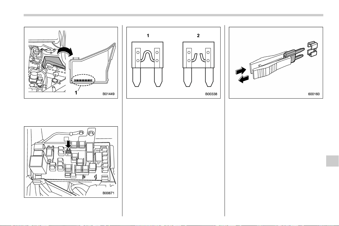
(541,1)
北米Model "A1700BE-B" EDITED: 2017/ 10/ 11
1) Spare fuses
The other one (main fuse box) is housed in
the engine compartment. Also, the spare
fuses are stored in the fuse box cover.
The fuse puller is stored in the main fuse
box in the engine compartment.
1) Good
2) Blown
If any lights, accessories or other electrical
controls do not operate, inspect the corre-
sponding fuse. If a fuse has blown, replace
it.
1. Turn the ignition switch to the “LOCK”/
“OFF” position and turn off all electrical
accessories.
2. Remove the cover.
3. Determine which fuse may be blown.
Look at the back side of each fuse box
cover and refer to “Fuses and circuits”
F12-10.
4. Pull out the fuse with the fuse puller.
5. Inspect the fuse. If i t has blown,
replace it with a spare fuse of the same
rating.
6. If the same fuse blows again, this
indicates that its system has a problem.
Contact your SUBARU dealer for repairs.
Maintenance and service/Fuses
11-43
11
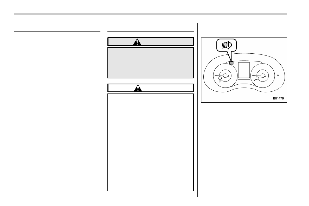
(542,1)
北米Model "A1700BE-B" EDITED: 2017/ 10/ 11
Installation of accessories
Always consult your SUBARU dealer
before installing fog lights or any other
electrical equipment in your vehicle. Such
accessories may cause the electronic
system to malfunction if they are incor-
rectly installed or if they are not suited for
the vehicle.
Replacing bulbs
WARNING
Bulbs may become very hot while
illuminated. Before replacing bulbs,
turn off the lights and wait until the
bulbs cool down. Otherwise, there is
a risk of sustaining a burn injury.
CAUTION
. Replace any bulb only with a new
bulb of the specified wattage.
Using a bulb of different wattage
could result in a fire. For the
specified wattage of each bulb,
refer to “Bulb chart” F12-14.
. Do not touch the glass portion of
the light bulb with bare hands.
When holding the glass portion is
unavoidable, hold it using with a
clean dry cloth to avoid getting
moisture and grease on the bulb.
Ifthereisanyfingerprintsor
grease on the bulb surface, wipe
them away with a soft cloth
moistened with alcohol. Also, if
the bulb is scratched or dropped,
it may blow out or crack.
& Headlights (models with LED
headlights)
The LED headlight warning light illumi-
nates if the LED headlights malfunction.
Have your vehicle inspected at a SUBARU
dealer as soon as possible.
& High beam headlight (models
without LED headlights)
NOTE
. If headlight aiming is required, con-
sult your SUBARU dealer for proper
adjustment of the headlight aim.
. It may be difficult to replace the
bulbs. Have the bulbs replaced by your
SUBARU dealer if necessary.
Perform the following steps to replace the
bulbs.
Maintenance and service/Installation of accessories
11-44
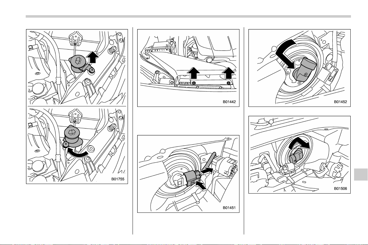
(543,1)
北米Model "A1700BE-B" EDITED: 2017/ 10/ 11
Left-hand side
1. Left-hand side: Use a screwdriver to
remove the secured clip of the washer
tank. To make it easy to access the bulb,
turn the neck of the washer fluid filler pipe
as illustrated.
Right-hand side
Right-hand side: Use a screwdriver to
undo the clips on the air intake duct, then
remove the air intake duct.
2. Disconnect the electrical connector
from the bulb as pushing the tab.
Left-hand side
Right-hand side
3. Left-hand side: Remove the bulb from
the headlight assembly by turning it
counterclockwise.
Right-hand side: Remove the bulb from
– CONTINUED –
Maintenance and service/Replacing bulbs
11-45
11
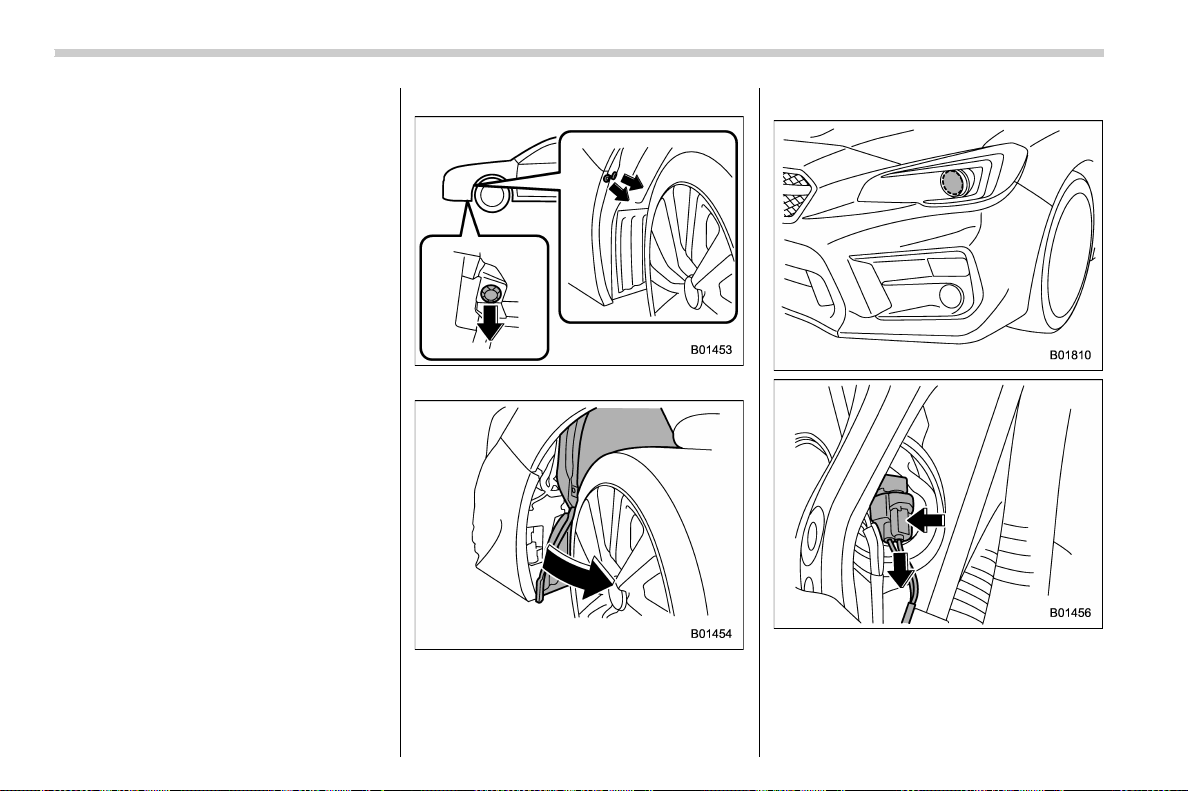
(544,1)
北米Model "A1700BE-B" EDITED: 2017/ 10/ 11
the headlight assembly by turning it clock-
wise.
4. Replace the bulb with a new one. At
this time, use care not to touch the bulb
surface.
5. To install the bulb to the headlight
assembly, turn it to the reverse direction
until it clicks.
6. Reconnect the electrical connector.
7. Left-hand side: Set the washer fluid
filler pipe to the original place and secure it
by a clip.
Right-hand side: Install the air intake duct
with clips.
& Low beam headlight*, front
side marker light, parking
light* and front turn signal
light*
*: models without LED headlights
NOTE
. If headlight aiming is required, con-
sult your SUBARU dealer for proper
adjustment of the headlight aim.
. It may be difficult to replace the
bulbs. Have the bulbs replaced by your
SUBARU dealer if necessary.
1. Start the engine and turn the steering
wheel fully in the opposite direction of the
bulb to be replaced.
2. Stop the engine.
3. Remove the clips from the mud guard.
4. Pull off the mud guard.
! Low beam headlight
1. Disconnect the electrical connector
from the bulb as pushing the tab.
Maintenance and service/Replacing bulbs
11-46
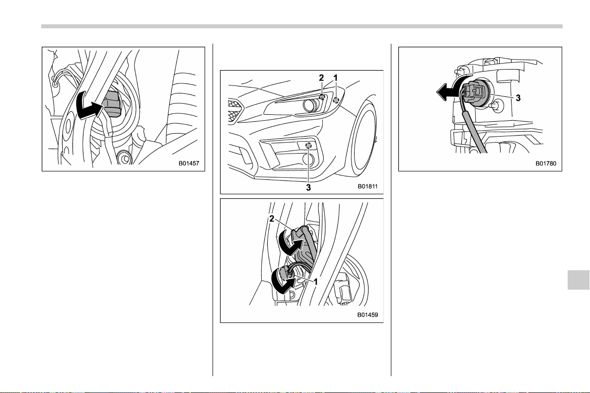
(545,1)
北米Model "A1700BE-B" EDITED: 2017/ 10/ 11
2. Remove the bulb from the headlight
assembly by turning it counterclockwise.
3. Replace the bulb with a new one. At
this time, use care not to touch the bulb
surface.
4. To install the bulb to the headlight
assembly, turn it clockwise until it clicks.
5. Reconnect the electrical connector.
6. Reattach the mud guard.
! Front side marker light, parking light
and front turn signal light
1) Front side marker light
2) Parking light
3) Front turn signal light
1. Turn the socket counterclockwise and
pull it out.
2. Pull out the bulb from the socket and
replace the bulb with a new one.
3. After replacing the bulb, reattach the
mud guard.
– CONTINUED –
Maintenance and service/Replacing bulbs
11-47
11
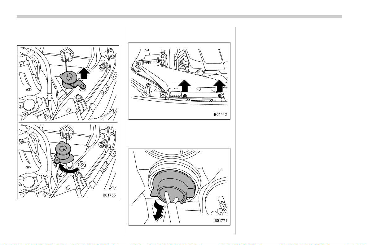
(546,1)
北米Model "A1700BE-B" EDITED: 2017/ 10/ 11
& Front turn signal light (mod-
els with LED headlights)
Left-hand side
1. Left-hand side: Use a screwdriver to
remove the secured clip of the washer
tank. To make it easy to access the bulb,
turn the neck of the washer fluid filler pipe
as illustrated.
Right-hand side
Right-hand side: Use a screwdriver to
undo the clips on the air intake duct, then
remove the air intake duct.
2. Remove the bulb from the headlight
assembly by turning it counterclockwise.
3. Replace the bulb with a new one. At
this time, use care not to touch the bulb
surface.
4. To install the bulb to the headlight
assembly, turn it clockwise until it clicks.
5. Left-hand side: Set the washer fluid
filler pipe to the original place and secure it
with a clip.
Right-hand side: Install the air intake duct
with clips.
& Front fog light (models with
the LED front fog light)
Have the front fog light assembly checked
by your SUBARU dealer.
Maintenance and service/Replacing bulbs
11-48
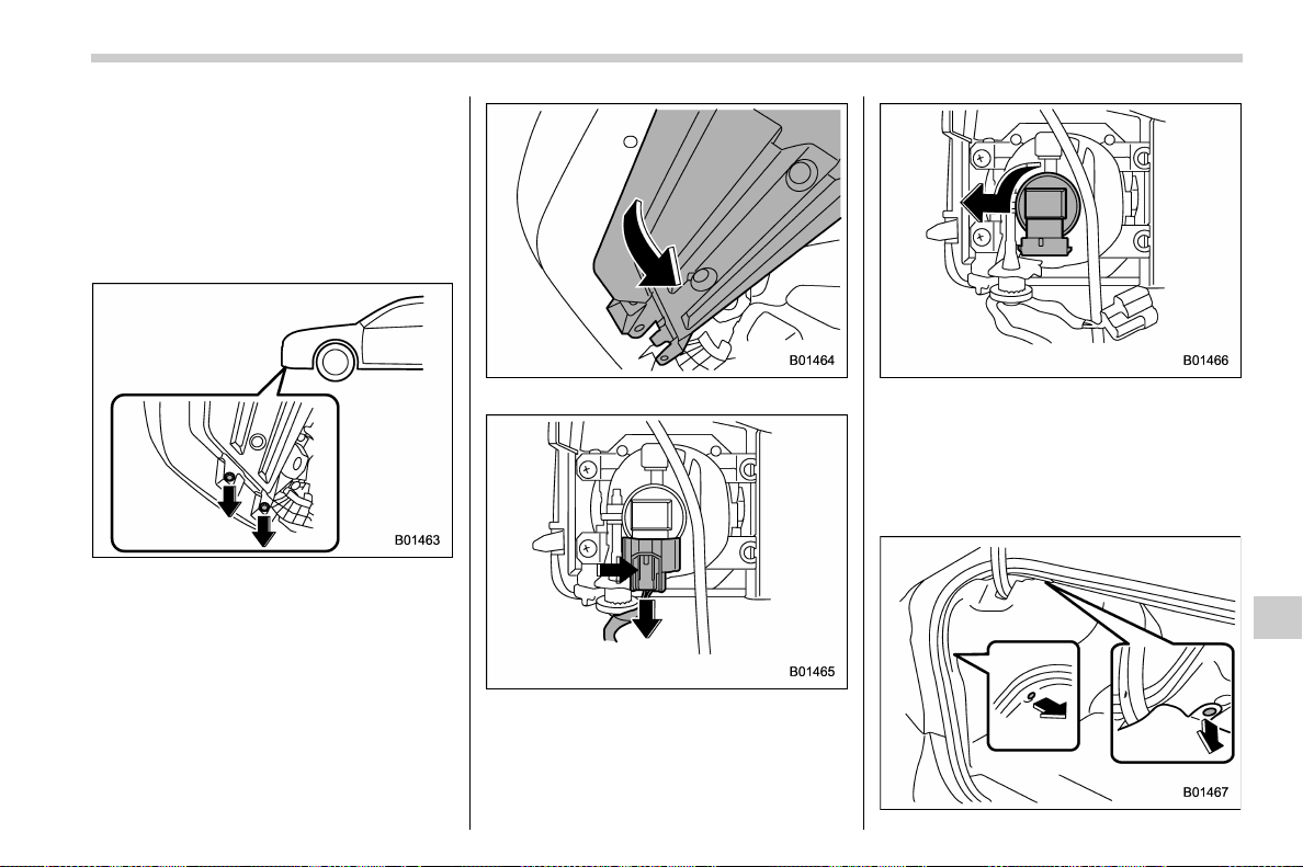
(547,1)
北米Model "A1700BE-B" EDITED: 2017/ 10/ 11
& Front fog light (models with-
out the LED front fog light) (if
equipped)
NOTE
It may be difficult to replace the bulbs.
Have the bulbs replaced by your
SUBARU dealer if necessary.
1. Remove the clips.
2. Turn over the mud guard.
3. Disconnect the electrical connector
from the bulb as pushing the tab.
4. Remove the bulb by turning it counter-
clockwise.
5. Replace the bulb with a new one.
6. Reattach the mud guard.
& Rear combination lights
– CONTINUED –
Maintenance and service/Replacing bulbs
11-49
11
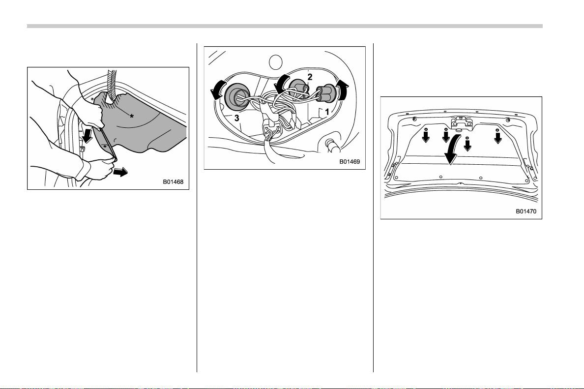
(548,1)
北米Model "A1700BE-B" EDITED: 2017/ 10/ 11
1. Remove the clips from the trunk trim
with a flat-head screwdriver.
2. Open the rear portion of the trunk trim
panel as illustrated.
NOTE
Make sure that the “*” part of the trunk
trim in the illustration does not contact
the trunk lid stay. If the “
*” part is bent,
the trunk trim may be torn.
1) Rear side marker light
2) Backup light
3) Rear turn signal light
3. Remove the bulb socket from the rear
combination light assembly by turning it
counterclockwise.
4. Pull the bulb out of the bulb socket and
replace it with a new one.
5. Set the bulb socket into the rear
combination light assembly and turn it
clockwise until it locks.
6. Secure the rear trunk trim panel with
the clips.
NOTE
When replacing a bulb of the rear side
marker light, detach the bulb socket of
the backup light in ad vance. Afte r
replacing the bulb, first attach the side
marker light, and then attach the back-
up light.
& License plate light
1. Open the trunk and remove the clips
from the trunk lid trim with a flat-head
screwdriver.
2. Turn over the trunk lid trim.
Maintenance and service/Replacing bulbs
11-50
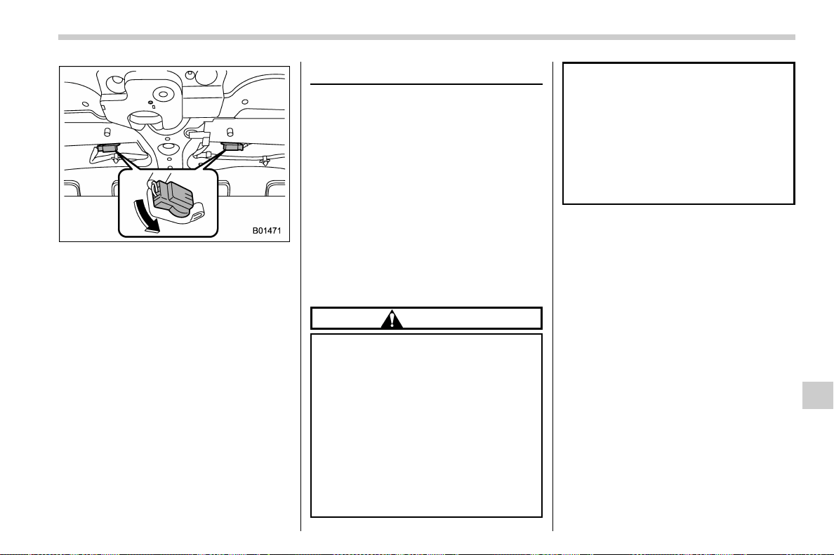
(549,1)
北米Model "A1700BE-B" EDITED: 2017/ 10/ 11
3. Turn the bulb socket counterclockwise
and pull out the socket.
4. Pull the bulb out of the socket.
5. Install a new bulb.
6. Reinstall the bulb socket and the trunk
lid trim.
& Other bulbs
It may be difficult to replace the bulbs.
Have the bulbs replaced by your
SUBARU dealer if necessary.
Replacing battery
The access key fob/transmitter battery
may be discharged under the following
conditions.
. The operation of the keyless access
function is unstable
. The operating distance of the remote
keyless entry system is unstable
. The transmitter does not operate prop-
erly when used within the standard dis-
tance
Replace the battery with a new one.
& Safety precautions
CAUTION
. Do not let dust, oil or water get on
or in the access key fob/transmit-
ter when replacing battery.
. Before replacing the battery, re-
move any static electricity.
. Be careful not to touch or damage
the printed circuit board in the
access key fob/transmitter when
replacing the battery.
. Be careful not to allow children to
touch the battery and any re-
moved parts; children could
swallow them.
. There is a danger of an explosion
if the battery is incorrectly re-
placed. Replace only with the
same or equivalent type of the
battery.
. Do not expose batteries to exces-
sive heat such as bright sunlight,
fire or the like.
NOTE
. Replace only with the same or
equivalent type of battery recom-
mended by the manufacturer.
. Dispose of used batteries according
to local laws.
. Mount the battery in the correct
orientation to prevent fluid leakage.
Be careful not to bend the terminals. It
may result in a malfunction.
. It is recommended that the battery
should be replaced by a SUBARU deal-
er.
. Use a new battery.
. After replacing the battery, confirm
that the access key fob/transmitter
functions properly.
– CONTINUED –
Maintenance and service/Replacing battery
11-51
11
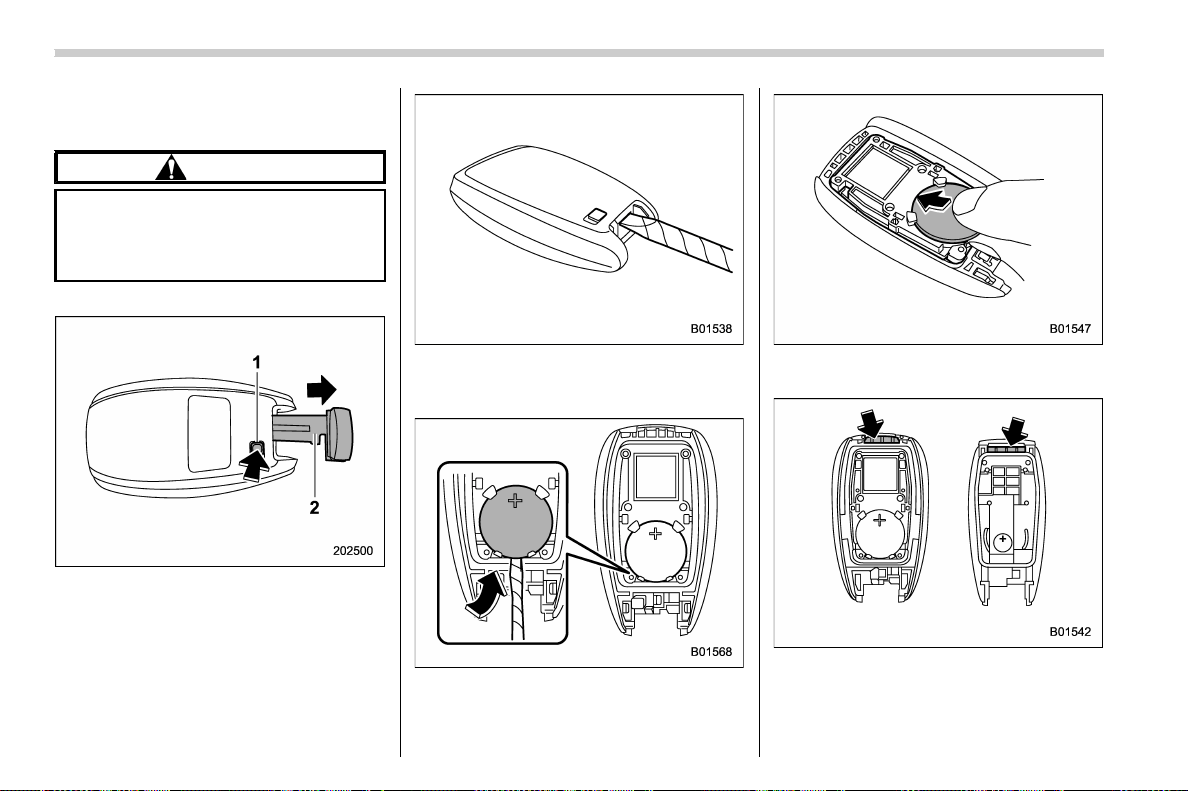
(550,1)
北米Model "A1700BE-B" EDITED: 2017/ 10/ 11
& Replacing battery of access
key fob
CAUTION
When removing or reinstalling the
access key fob cover, make sure that
the plastic part does not come off or
become misaligned.
Battery: Button battery CR2032
1) Release button
2) Emergency key
1. Take out the emergency key.
2. Wrap a flat-head screwdriver with vinyl
tape or a cloth, and insert it in the gap to
remove the cover.
3. Take out the battery using a flat-head
screwdriver with vinyl tape or a cloth.
4. Insert a new battery with its positive (+)
side facing upward as shown in the figure.
5. Attach the cover to the access key fob
by fitting the projections and recesses
together.
6. Reinstall the emergency key.
Maintenance and service/Replacing battery
11-52
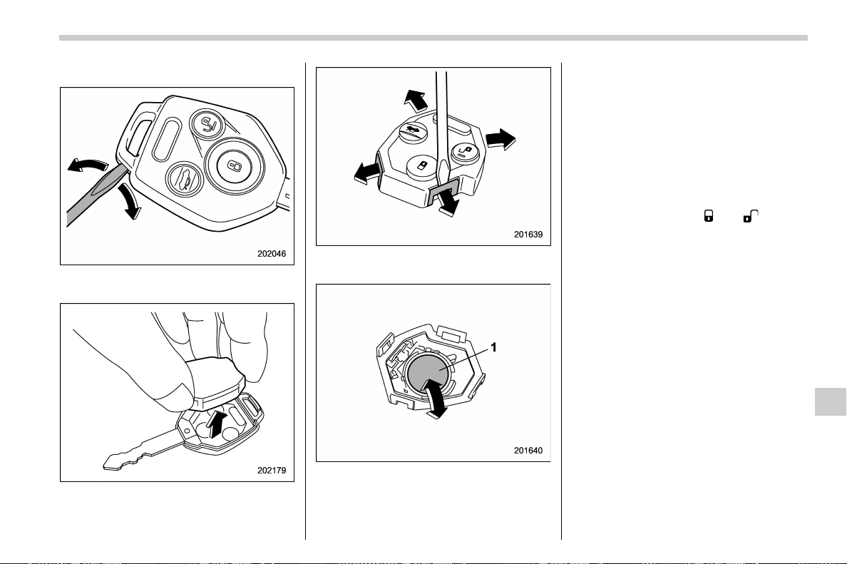
(551,1)
北米Model "A1700BE-B" EDITED: 2017/ 10/ 11
& Replacing transmitter battery
1. Open the key head using a flat-head
screwdriver.
2. Remove the transmitter case from the
key head.
3. Open the transmitter case by releasing
the hooks.
1) Negative (−) side facing up
4. Replace the old battery with a new
battery (type CR1620 or equivalent) mak-
ing sure to install the new battery with the
negative (−) side facing up.
5. Put together the transmitter case by
fitting the hooks on the case.
6. Reinstall the transmitter case in the
key head.
7. Refit the removed half of the key head.
After the battery is replaced, the trans-
mitter must be synchronized with the
remote keyless entry system’s control
unit. Press either the “
” or “ ” button
six times to synchronize the unit.
Maintenance and service/Replacing battery
11-53
11

Black plate (2,1)
Model "ALL_MODEL_MEMO" EDITED: 2007/ 6/ 22
Left Page
————————————————————————————————————————
————————————————————————————————————————
————————————————————————————————————————
————————————————————————————————————————
————————————————————————————————————————
————————————————————————————————————————
————————————————————————————————————————
————————————————————————————————————————
————————————————————————————————————————
————————————————————————————————————————
————————————————————————————————————————
————————————————————————————————————————
————————————————————————————————————————

(555,1)
北米Model "A1700BE-B" EDITED: 2017/ 10/ 11
Specifications........................................................ 12-2
Dimensions...........................................................12-2
Engine ..................................................................12-3
Fuel ...................................................................... 12-3
Engine oil .............................................................12-4
Manual transmission, front differential and rear
differential gear oil..............................................12-6
Fluids ...................................................................12-7
Engine coolant...................................................... 12-7
Electrical system ..................................................12-8
Tires..................................................................... 12-8
Temporary spare tires........................................... 12-9
Brake disc ............................................................ 12-9
Fuses and circuits .............................................. 12-10
Fuse panel located in the passenger
compartment ................................................... 12-10
Fuse panel located in the engine compartment ... 12-12
Bulb chart............................................................ 12-14
Vehicle identification .......................................... 12-16
Specifications
12

(556,1)
北米Model "A1700BE-B" EDITED: 2017/ 10/ 11
Specifications
These specifications are subject to change without notice.
& Dimensions
in (mm)
Item TYPE RA Except TYPE RA
Overall length 181.9 (4,620) 180.9 (4,595)
Overall width 70.7 (1,795)
Overall height
58.1 (1,475)
Wheel base 104.3 (2,650)
Tread
Front 60.2 (1,530)
Rear 60.6 (1,540)
Ground clearance
4.9 (125)
Specifications/Specifications
12-2
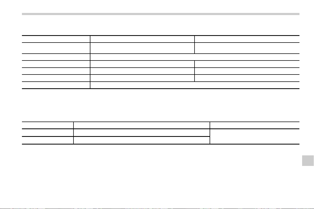
(557,1)
北米Model "A1700BE-B" EDITED: 2017/ 10/ 11
& Engine
Model
STI Except STI
Engine model
EJ25
(2.5 L, DOHC, turbo)
FA20
(2.0 L, DOHC, turbo)
Engine type Horizontally opposed, liquid cooled 4 cylinder, 4-stroke petrol engine
Displacement cu-in (cc) 150 (2,457) 122 (1,998)
Bore 6 Stroke in (mm) 3.92 6 3.11 (99.5 6 79.0) 3.39 6 3.39 (86.0 6 86.0)
Compression ratio 8.2 : 1 10.6 : 1
Firing order
1 – 3 – 2 – 4
& Fuel
NOTE
The engine is designed to operate using unleaded gasoline.
Model Fuel Fuel tank capacity
STI
93 AKI (98 RON) or higher*
1
15.9 US gal (60 liters, 13.2 Imp gal)
Except STI
91 AKI (95 RON) or higher*
2
*1: If unleaded gasoline with an octane rating of 93 AKI (98 RON) is not available, unleaded gasoline with an octane rating of 91 AKI (95 RON) may be
used with no detriment to engine durability or driveability.
*2: If unleaded gasoline with an octane rating of 91 AKI (95 RON) is not available, unleaded gasoline with an octane rating of 87 AKI (90 RON) or higher
may be used.
– CONTINUED –
Specifications/Specifications
12-3
12

(558,1)
北米Model "A1700BE-B" EDITED: 2017/ 10/ 11
& Engine oil
For the checking, adding and replacing procedure or other details, refer to “Engine oil” F11-13.
NOTE
Have the procedure for changing the engine oil and oil filter performed by a properly-trained expert. It is recommended that
you have this service performed by your SUBARU dealer.
! Approved engine oil
Always use the SUBARU approved engine oil. For further details, please contact your SUBARU dealer.
If the approved engine oil is unavailable, use the alternative engine oil described on the next page.
Specifications/Specifications
12-4
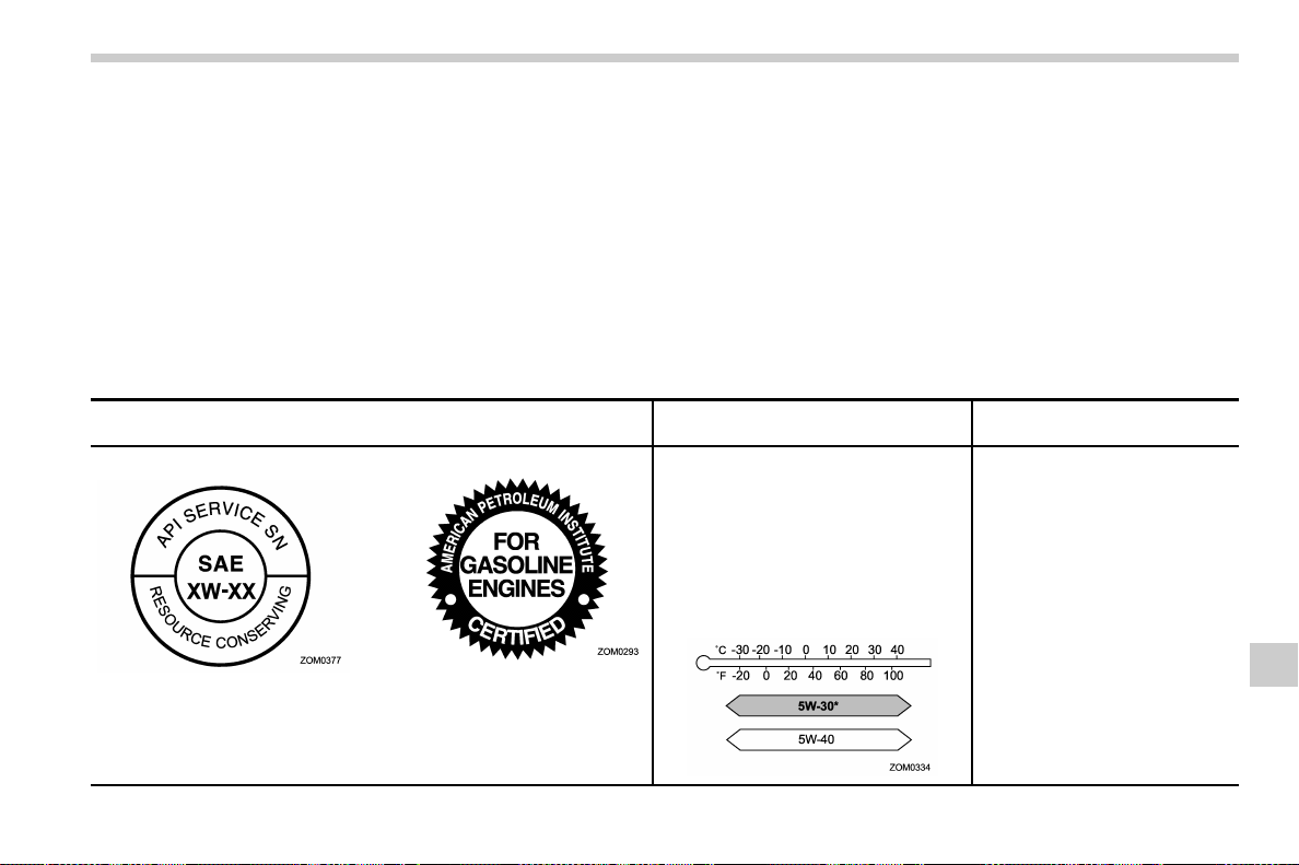
(559,1)
北米Model "A1700BE-B" EDITED: 2017/ 10/ 11
! Alternative engine oil
If the SUBARU approved oil is unavailable, the following alternative oil can be used.
NOTE
. Each quantity indicated here is only a guideline. The necessary quantity for replacement may differ slightly depending on
the temperature and other factors.
. In choosing an oil, you want the proper quality and viscosity, as well as one that will enhance fuel economy. Oils of lower
viscosity provide better fuel economy. However, in hot weather, oil of higher viscosity is required to properly lubricate the
engine. The following table lists the recommended viscosities and applicable temperatures.
. When adding oil, you may use different brands together as long as they are the same API classification and SAE viscosity
as those recommended by SUBARU.
Oil grade
SAE viscosity No. and
applicable temperature
Engine oil capacity
API (American Petroleum Insti-
tute) classification SN with the
words “RESOURCE CONSER-
VING”
or
ILSAC (International Lubricant
Specification Advisory Commit-
tee) GF-5, which can be identi-
fied with the ILSAC certification
mark (Starburst mark)
5W-30 synthetic oil is the required oil for
optimum engine performance and pro-
tection. Conventional oil may be used if
synthetic oil is unavailable.
*: If 5W-30 synthetic oil is not available,
5W-40 conventional oil may be used if
replenishment is needed but should be
changed to 5W-30 synthetic oil at the
next oil change.
STI:
· Adding the oil from L to F level:
1.1 US qt (1.0 liter, 0.9 Imp qt)
· Changing the oil and oil filter:
4.5 US qt (4.3 liters, 3.8 Imp qt)
· Changing the oil:
4.2 US qt (4.0 liters, 3.5 Imp qt)
Except STI:
· Adding the oil from L to F level:
1.1 US qt (1.0 liter, 0.9 Imp qt)
· Changing the oil and oil filter:
5.4 US qt (5.1 liters, 4.5 Imp qt)
· Changing the oil:
5.2 US qt (4.9 liters, 4.3 Imp qt)
– CONTINUED –
Specifications/Specifications
12-5
12
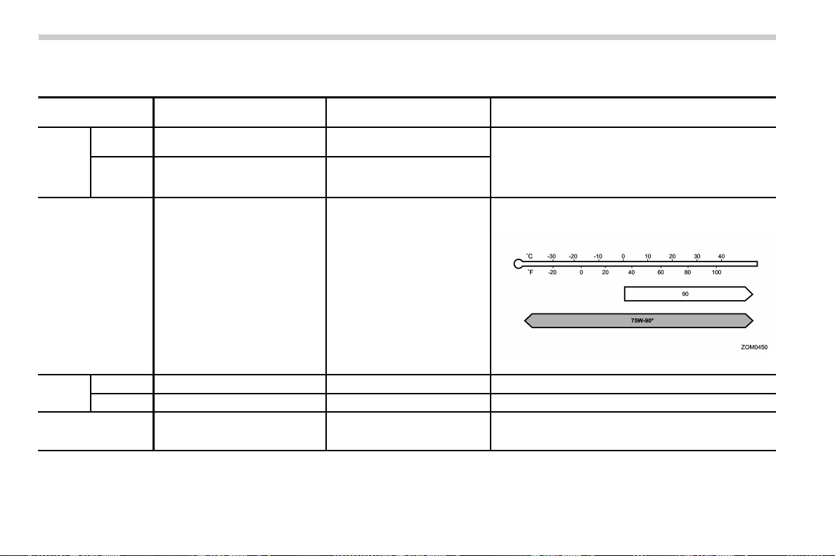
(560,1)
北米Model "A1700BE-B" EDITED: 2017/ 10/ 11
& Manual transmission, front differential and rear differential gear oil
Oil Manual transmission oil
Front differential gear oil (CVT
models)
Rear differential gear oil
Oil
grade
STI
. API classification GL-5
(75W-90)*
3
—
API classification GL-5
Except STI
. SUBARU Extra MT*
3
. API classification GL-5
(75W-90)*
4
. SUBARU Extra MT*
3
. API classification GL-5
(75W-90)
SAE viscosity No. and
applicable tempera-
ture
——
. 75W-90*
. 90
*: recommended
Oil ca-
pacity*
1
STI 4.3 US qt (4.1 liters, 3.6 Imp qt) — 1.1 US qt (1.0 liter, 0.9 Imp qt)
Except STI 3.5 US qt (3.3 liters, 2.9 Imp qt) 1.5 US qt (1.4 liters, 1.2 Imp qt) 0.8 US qt (0.8 liters, 0.7 Imp qt)
Remarks*
2
“Manual transmission oil” F11-22
“Front differential gear oil (CVT
models) and rear differential gear
oil” F11-23
“Front differential gear oil (CVT models) and rear differential
gear oil ” F11-23
*1: The indicated oil quantity is only a guideline. The necessary quantity for replacement may differ slightly depending on the temperature and other
factors. Check the oil level after refilling the gearbox with oil.
*2: For more details about maintenance and service, refer to the indicated section.
*3: The vehicle is filled at the factory with this oil.
*4: You may use this type of manual transmission oil. However, using this type of oil will detract from driveability and fuel efficiency.
Specifications/Specifications
12-6
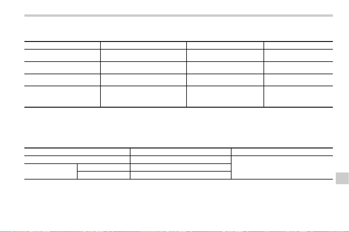
(561,1)
北米Model "A1700BE-B" EDITED: 2017/ 10/ 11
& Fluids
Fluid
Fluid type*
1
Fluid capacity*
2
Remarks*
3
Continuously variable transmission
fluid (CVT models)
Consult your SUBARU dealer. 13.1 US qt (12.4 liters, 10.9 Imp qt)
“
Continuously variable transmis-
sion fluid” F11-22
Brake fluid
FMVSS No. 116, DOT 3 or DOT 4 brake
fluid
—“Brake fluid” F11-24
Clutch fluid (MT models)
FMVSS No. 116, DOT 3 or DOT 4 brake
fluid
—“
Clutch fluid (MT models)” F11-25
Power steering fluid (STI)
· SUBARU ATF
· “Dexron III” Type Automatic Transmis-
sion Fluid
· IDEMITSU ATF HP
0.7 US qt (0.7 liter, 0.6 Imp qt)
“
Power steering fluid (STI)” F11-
23
*1: Use one of the indicated types of fluid.
*2: The indicated fluid quantity is only a guideline. The necessary quantity for replacement may differ slightly depending on the temperature and other
factors.
*3: For more details about maintenance and service, refer to the indicated section.
& Engine coolant
Vehicle model Coolant capacity Coolant type
STI 8.2 US qt (7.7 liters, 6.8 Imp qt)
SUBARU Super Coolant
Except STI
MT models 8.6 US qt (8.1 liters, 7.2 Imp qt)
CVT models
8.8 US qt (8.3 liters, 7.3 Imp qt)
The indicated coolant quantity is only a guideline. The necessary quantity for replacement may differ slightly depending on the temperature and other
factors. For more details about maintenance and service, refer to “
Cooling system” F11-16.
– CONTINUED –
Specifications/Specifications
12-7
12

(562,1)
北米Model "A1700BE-B" EDITED: 2017/ 10/ 11
& Electrical system
Alternator
STI 12V-110A
Except STI 12V-130A
Spark plugs
TYPE RA ILFR7H (NGK)
STI except TYPE RA SILFR6A (NGK)
Except STI
ILKAR8H6 (NGK)
& Tires
Tire size
STI — 245/40R18 97W 245/35R19 89W
Except STI 235/45R17 94W 245/40R18 97W —
Wheel size
17 6 8J 18 6 8 1/2J 19 6 8 1/2J
Pressure Front
33 psi (230 kPa, 2.3 kgf/cm
2
)
Rear
32 psi (220 kPa, 2.2 kgf/cm
2
)
Wheel nut tightening torque
89 lbf·ft (120 N·m, 12 kgf·m)*
1
*1: This torque is equivalent to applying approximately 88 to 110 lbf (40 to 50 kgf) at the end of the wheel nut wrench. If you have tightened the wheel nuts
by yourself, have the tightening torque checked at the nearest automotive service facility as soon as possible. For the wheel nut tightening procedure,
refer to “Changing a flat tire” F9-5.
Specifications/Specifications
12-8
(563,1)
北米Model "A1700BE-B" EDITED: 2017/ 10/ 11
& Temporary spare tires
Temporary spare tire size T145/70D17 T135/70D18 205/50R17 205/45R18
Temporary spare tire inflation pressure
(recommended cold tire inflation pressure)
60 psi (420 kPa, 4.2 kgf/cm
2
) 33 psi (230 kPa, 2.3 kgf/cm
2
) 38 psi (260 kPa, 2.6 kgf/cm
2
)
Wheel nut tightening torque
89 lbf·ft (120 N·m, 12 kgf·m)*
1
*
2
*1: This torque is equivalent to applying approximately 88 to 110 lbf (40 to 50 kgf) at the end of the wheel nut wrench. If you have tightened the wheel nuts
by yourself, have the tightening torque checked at the nearest automotive service facility as soon as possible.
*2: For the wheel nut tightening procedure, refer to “Changing a flat tire” F9-5.
& Brake disc
If you need information on the usage limit value of brake discs and the method for measuring them, consult your SUBARU dealer.
Specifications/Specifications
12-9
12
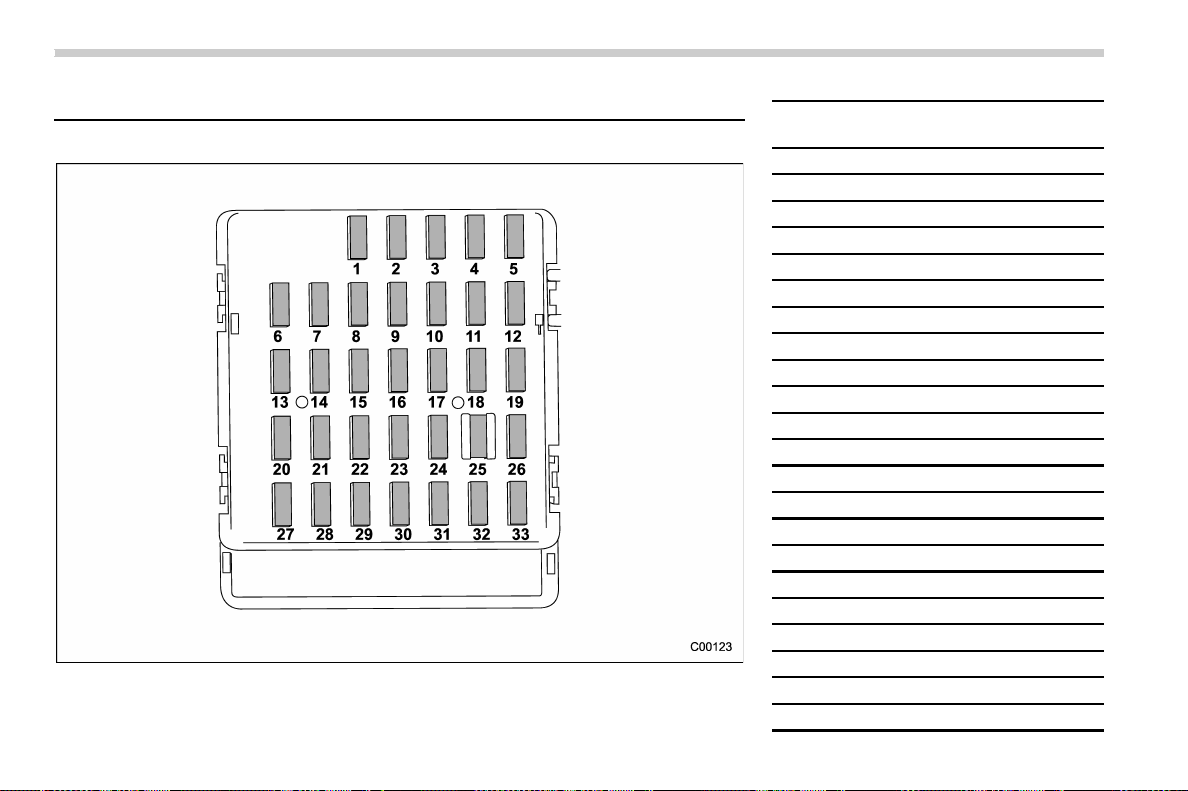
(564,1)
北米Model "A1700BE-B" EDITED: 2017/ 10/ 11
Fuses and circuits
& Fuse panel located in the passenger compartment
Fuse
panel
Fuse
rating
Circuit
1 20A
R.FOG TRAIL
2 7.5A METER IG
3 15A DOOR LOCK
4 10A
IG2
5 Empty
6 7.5A
MIR
7 15A
UNIT+B
8 7.5A
STOP
9 7.5A
WIPER DEICE
10 7.5A
D-OP+B
11 7.5A
TURN IG
12 15A
UNIT IG1
13 20A
12V PLUG
14 10A
TAIL CLEARANCE
15 10A BKUP+B
16 7.5A
ILM
17 15A
SEAT HTR
18 10A
LAMP IG
19 Empty
20 10A
CIGAR
21 10A
START
22 7.5A
A/C IG
Specifications/Fuses and circuits
12-10

(565,1)
北米Model "A1700BE-B" EDITED: 2017/ 10/ 11
Fuse
panel
Fuse
rating
Circuit
23 Empty
24 10A
AUDIO NAVI
25 15A
SRS AIR BAG
26 7.5A
IG1
27 15A
BLOWER
28 15A
BLOWER
29 15A
F.FOG
30 Empty
31 7.5A
ACC
32 7.5A
STR LOCK
33 7.5A
UNIT IG2
– CONTINUED –
Specifications/Fuses and circuits
12-11
12
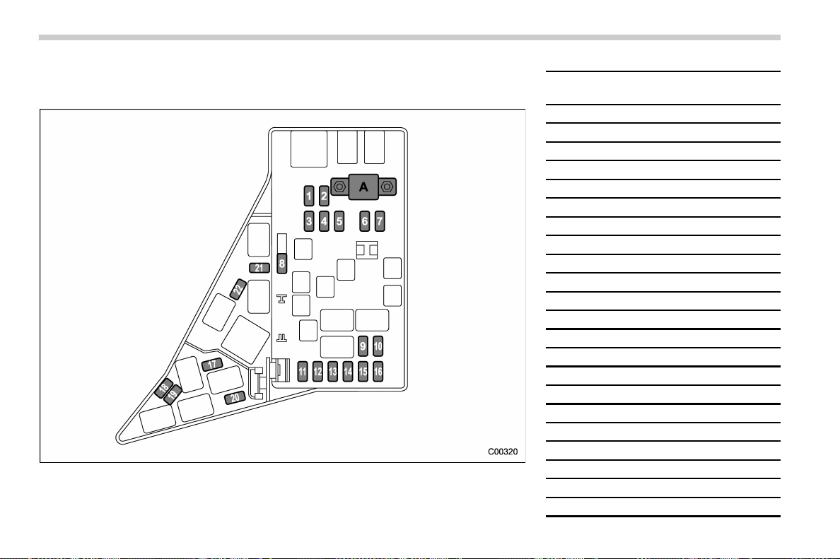
(566,1)
北米Model "A1700BE-B" EDITED: 2017/ 10/ 11
& Fuse panel located in the engine compartment
! STI
A) Main fuse
Fuse
panel
Fuse
rating
Circuit
1 30A
ABS SOL
2 25A MAIN FAN
3 25A
SUB FAN
4
Empty
5
25A AUDIO AMP
6
30A H/L LO
7
15A H/L HI
8 20A
BACK UP
9 15A
HORN
10 25A
R.DEF
11 15A
FUEL PI, P
12 10A
(Transmission control unit)
13 7.5A
EGI+B
14 15A
HAZARD
15 15A
LIGHTING
16 7.5A
ALT-S
17 Empty
18 20A
INJ
19 15A
H/L LO RH
20 15A
H/L LO LH
21 10A
AIR CUT
22 7.5A
(Telematics)
Specifications/Fuses and circuits
12-12
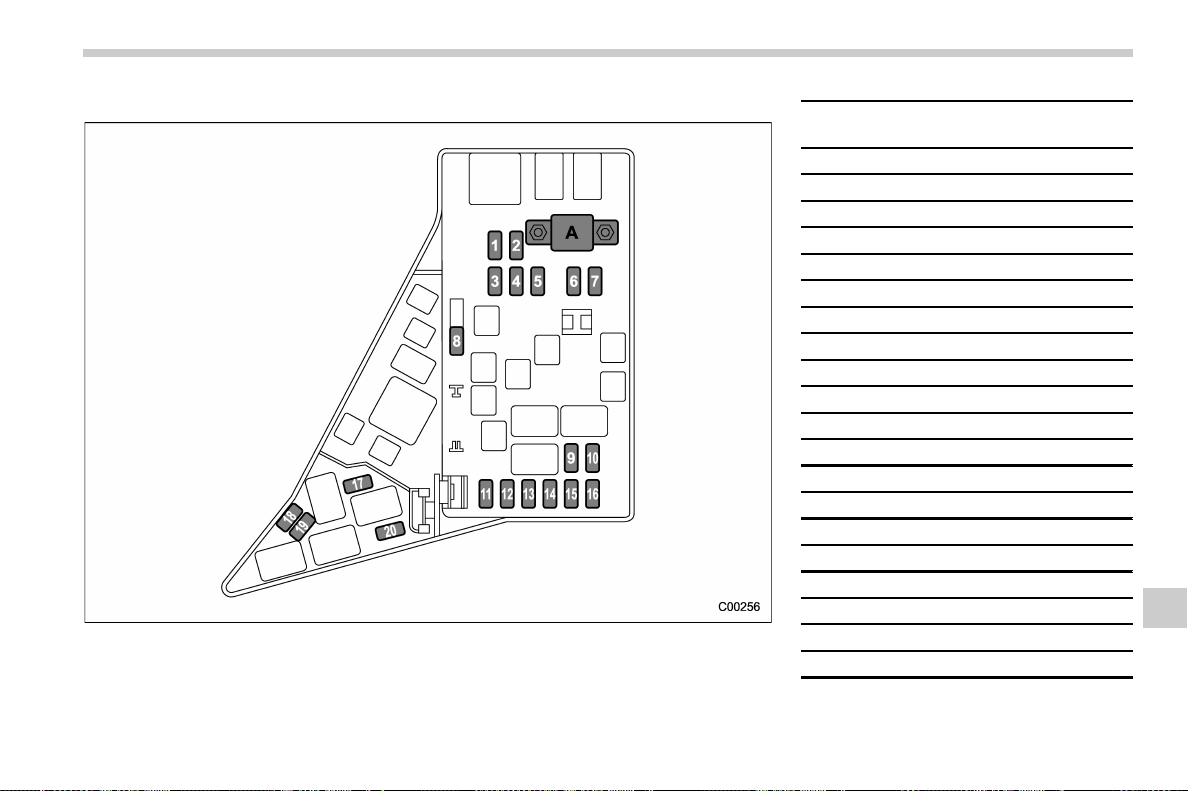
(567,1)
北米Model "A1700BE-B" EDITED: 2017/ 10/ 11
! Except STI
A) Main fuse
Fuse
panel
Fuse
rating
Circuit
1 30A
ABS SOL
2 25A MAIN FAN
3 25A
SUB FAN
4
Empty
5
25A AUDIO AMP
6
30A H/L LO
7
15A H/L HI
8 20A
BACK UP
9 15A
HORN
10 25A
R.DEF
11 15A
FUEL PI, P
12 20A
(Transmission control unit)
13 7.5A
EGI+B
14 15A
HAZARD
15 15A
LIGHTING
16 7.5A
ALT-S
17 Empty
18 20A
INJ
19 15A
H/L LO RH
20 15A
H/L LO LH
Specifications/Fuses and circuits
12-13
12
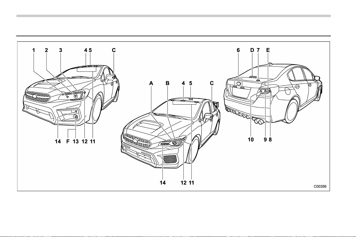
(568,1)
北米Model "A1700BE-B" EDITED: 2017/ 10/ 11
Bulb chart
NOTE
Lights indicated by letters are the LED (Light Emitting Diode) type. Consult your SUBARU dealer for replacement.
Specifications/Bulb chart
12-14
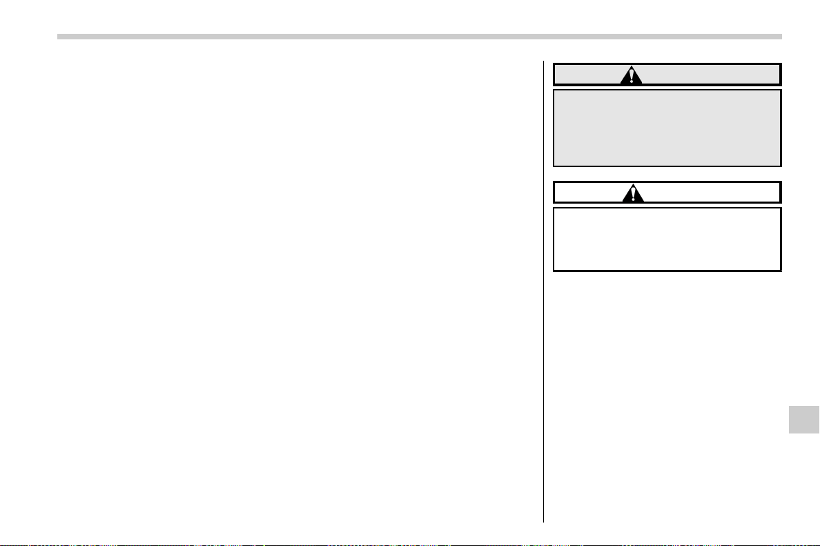
(569,1)
北米Model "A1700BE-B" EDITED: 2017/ 10/ 11
Wattage Bulb No.
1) High beam headlight (models without LED headlights) 12V-60W HB3
2) Low beam headlight (models without LED headlights) 12V-55W H11
3) Parking light (models without LED headlights) 12V-5W W5W
4) Map light
12V-8W –
5) Dome light 12V-8W –
6) License plate light 12V-5W W5W
7)
Trunk light 12V-5W W5W
8)
Rear side marker light 12V-5W W5W
9)
Backup light 12V-16W W16W
10)
Rear turn signal light 12V-21W WY21W
11)
Vanity mirror light 12V-2W –
12)
Front side marker light 12V-5W W5W
13)
Front fog light (models without LED fog lights) 12V-19W H16
14)
Front turn signal light 12V-21W WY21W
A)
Low and high beam headlight (models with LED
headlights)
––
B)
Parking light (models with LED headlights) ––
C)
Side turn signal light (if equipped) ––
D)
High-mounted stop light ––
E)
Stop light/Tail light ––
F)
Front fog light (models with LED fog lights) –
–
WARNING
Bulbs may become very hot while
illuminated. Before replacing bulbs,
turn off the lights and wait until the
bulbs cool down. Otherwise, there is
a risk of sustaining a burn injury.
CAUTION
Replace any bulb only with a new
bulb of the specified wattage. Using
a bulb of different wattage could
result in a fire.
Specifications/Bulb chart
12-15
12
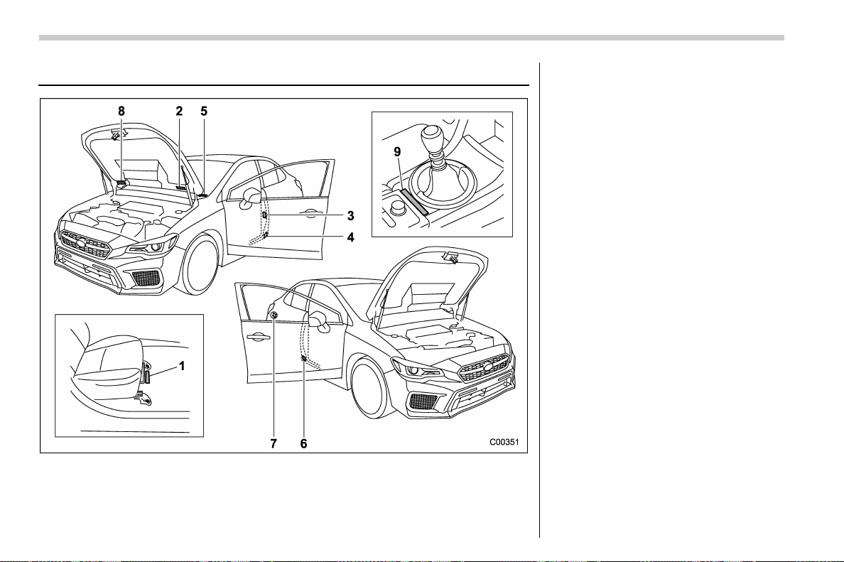
(570,1)
北米Model "A1700BE-B" EDITED: 2017/ 10/ 11
Vehicle identification
1) Vehicle identification number (under the
floor carpet of the right-hand front seat)
2) Emission control label
3) Tire inflation pressure label
4) Certification label
5) Vehicle identification number plate
6) Model number label
7) Fuel label
8) Air conditioner label
9) Serial number plate (TYPE RA)
Specifications/Vehicle identification
12-16

(573,1)
北米Model "A1700BE-B" EDITED: 2017/ 10/ 11
For U.S.A. .............................................................. 13-2
Tire information..................................................... 13-2
Tire labeling.......................................................... 13-2
Recommended tire inflation pressure ....................13-4
Glossary of tire terminology..................................13-5
Tire care – maintenance and safety practices ...... 13-10
Vehicle load limit – how to determine .................. 13-10
Determining compatibility of tire and vehicle
load capacities.................................................. 13-13
Adverse safety consequences of overloading
on handling and stopping and on tires............. 13-14
Steps for Determining Correct Load Limit ........... 13-14
Uniform tire quality grading standards............. 13-15
Treadwear........................................................... 13-15
Traction AA, A, B, C............................................ 13-15
Temperature A, B, C ........................................... 13-15
Reporting safety defects (U.S.A.) ...................... 13-16
Consumer information and Reporting safety defects
13
(574,1)
北米Model "A1700BE-B" EDITED: 2017/ 10/ 11
For U.S.A.
The following information has been
compiled according to Code of
Federal Regulations “Title 49, Part
575”.
Tire information
& Tire labeling
Many markings (e.g. Tire size, Tire
Identification Number or TIN) are
placed on the sidewall of a tire by
tire manufacturers. These markings
can provide you with useful infor-
mation on the tire.
! Tire size
Your vehicle comes equipped with
P-Metric tire size. It is important to
understand the sizing system in
selecting the proper tire for your
vehicles. Here is a brief review of
the tire sizing system with a break-
down of its individual elements.
! P Metric
With the P-Metric system, Section
Width is measured in millimeters.
To convert millimeters into inches,
divide by 25.4. The Aspect Ratio
(Section Height divided by Section
Width) helps provide more dimen-
sional information about the tire
size.
Example:
(1) P = Certain tire type used on
light duty vehicles such as passen-
ger cars
(2) Section Width in millimeters
(3) Aspect Ratio (= section height
7 section width).
(4) R = Radial Construction
(5) Rim diameter in inches
! Load and Speed Rating De-
scriptions
The load and speed rating descrip-
tions will appear following the size
designation.
They provide two important facts
about the tire. First, the number
designation is its load index. Sec-
ond, the letter designation indicates
the tire’s speed rating.
Consumer information and Reporting safety defects/For U.S.A.
13-2
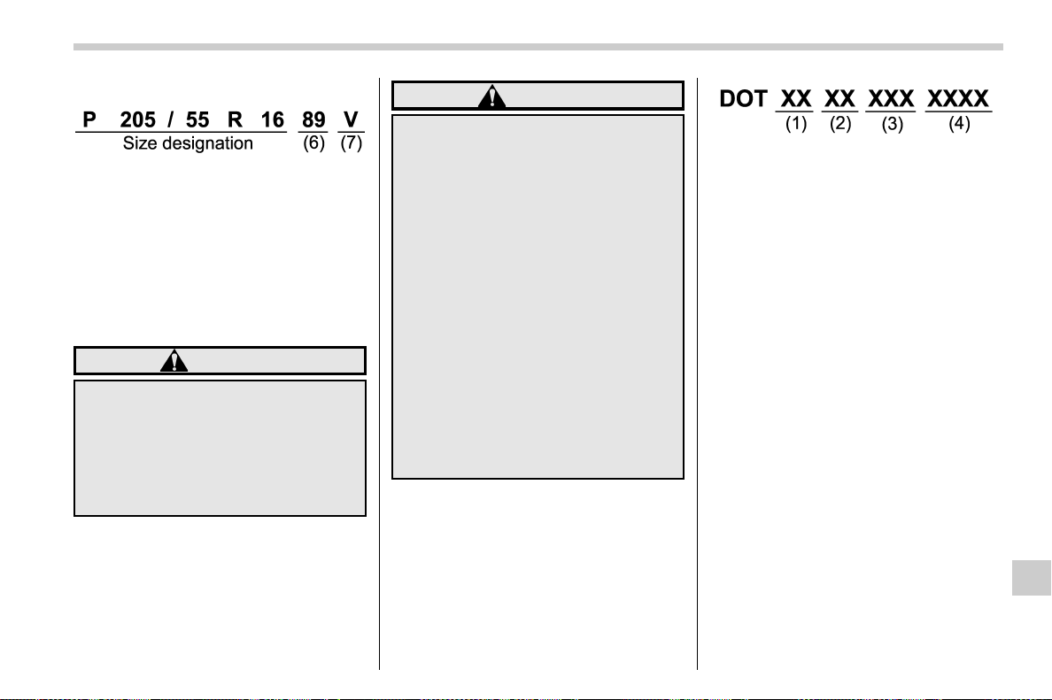
(575,1)
北米Model "A1700BE-B" EDITED: 2017/ 10/ 11
Example:
(6) Load Index: A numerical code
which specifies the maximum load
a tire can carry at the speed
indicated by its speed symbol, at
maximum inflation pressure.
For example, “90” means 1,323 lbs
(600 kg), “89” means 1,278 lbs (580
kg).
WARNING
Load indices apply only to the
tire, not to the vehicle. Putting
a load rated tire on any vehicle
does not mean the vehicle can
be loaded up to the tire’s rated
load.
(7) Speed Rating: An alphabetical
system describing a tire’s capability
to travel at established and prede-
termined speeds.
For example, “V” means 149 mph
(240 km/h)
WARNING
. Speed ratings apply only to
the tire, not to the vehicle.
Putting a speed rated tire on
any vehicle does not mean
the vehicle can be operated
at the tire’s rated speed.
. The speed rating is void if
the tires are worn out, da-
maged, repaired, retreaded,
or otherwise altered from
their original condition. If
tires are repaired, re-
treaded, or otherwise al-
tered, they may not be sui-
table for original equipment
tire designed loads and
speeds.
! Tire Identification Number (TIN)
Tire Identification Number (TIN) is
marked on the intended outboard
sidewall. The TIN is composed of
four groups. Here is a brief review of
the TIN with a breakdown of its
individual elements.
(1) Manufacture r’s Identification
Mark
(2) Tire Size
(3) Tire Type Code
(4) Date of Manufacture
The first two figures identify the
week, starting with “01” to represent
the first full week of the calendar
year; the second two figures repre-
sent the year. For example, 0101
means the 1st week of 2001.
! Other markings
The following makings are also
placed on the sidewall.
! Maximum permissible infla-
tion pressure
The maximum cold inflation pres-
sure to which this tire may be
inflated. For example, “300 kPa
(44 PSI) MAX. PRESS”
– CONTINUED –
Consumer information and Reporting safety defects/Tire information
13-3
13
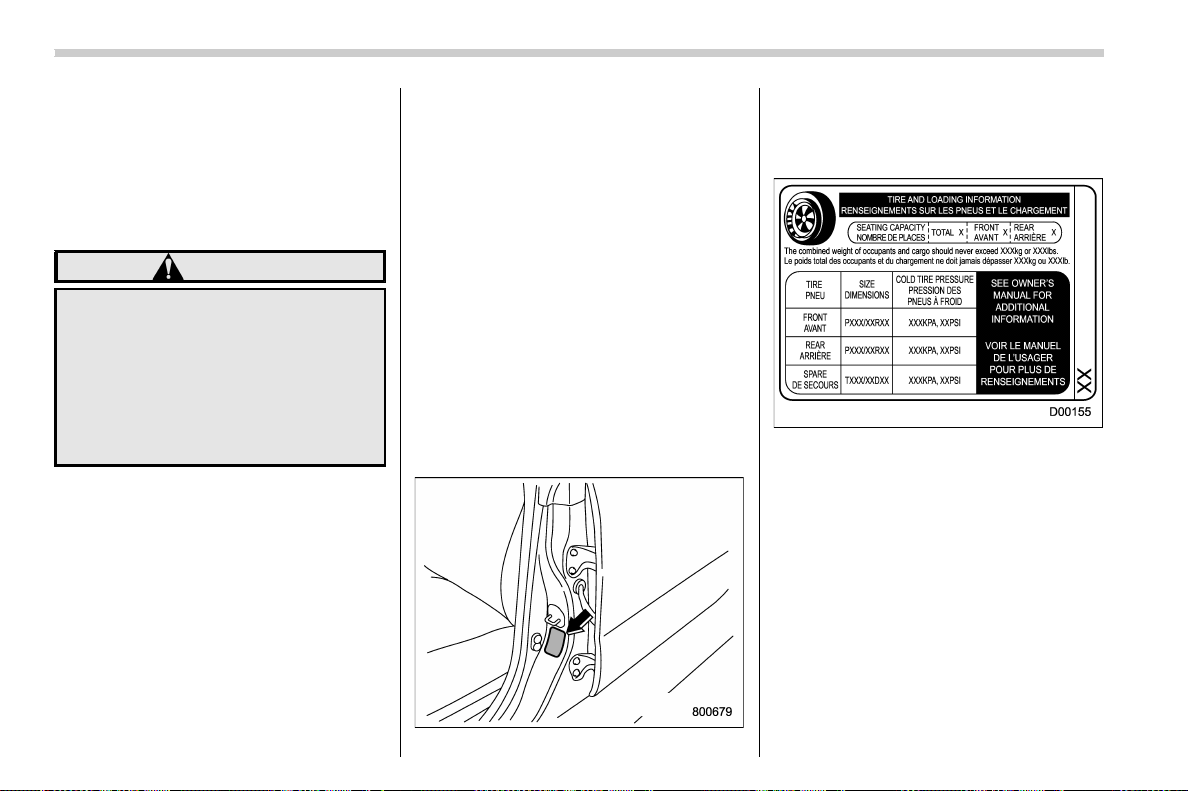
(576,1)
北米Model "A1700BE-B" EDITED: 2017/ 10/ 11
! Maximum load rating
The load rating at the maximum
permissible weight load for this tire.
For example, “MAX. LOAD 580 kg
(1279 LBS) @ 300 kPa (44 PSI)
MAX. PRESS.”
WARNING
Maximum load rating applies
only to the tire, not to the
vehicle. Putting a load rated
tire on any vehicle does not
mean the vehicle can be
loaded up to the tire’s rated
load.
! Construction type
Applicable construction of this tire.
For example, “TUBELESS STEEL
BELTED RADIAL”
! Construction
The generic name of each cord
material used in the plies (both
sidewall and tread area) of this tire.
For example, “PLIES: TREAD 2
STEEL + 2 POLYESTER SIDE -
WALL 2 POLYESTER”
! Uniform Tire Quality Grading
(UTQG)
For det ails, refer to “Uniform tire
quality grading standards” F13-15.
& Recommended tire inflation
pressure
! Recommended cold tire infla-
tion pressure
For recommended cold tire inflation
pressure for your vehicle’s tires,
refer to “
Tires” F12-8.
! Vehicle placard
The vehicle placard is affixed to the
driver’s side B-pillar.
Example:
The vehicle placard shows original
tire size, recommended cold tire
inflation pressure on each tire at
maximum loaded vehicle weight,
seating capacity and loading infor-
mation.
! Adverse safety consequences
of under-inflation
Driving at high speeds with exces-
sively low tire pressures can cause
the tires to flex severely and to
rapidly become hot. A sharp in-
Consumer information and Reporting safety defects/Tire information
13-4

(577,1)
北米Model "A1700BE-B" EDITED: 2017/ 10/ 11
crease in temperature could cause
tread separation, and failure of the
tire(s). Possible resulting loss of
vehicle con trol could lead to an
accident.
! Measuring and adjusting air
pressure to achieve proper in-
flation
Check and, if necessary, adjust the
pressure of each tire (including the
spare) at least once a month and
before any long journey. Check the
tire pressures when the tires are
cold. Use a pressure gauge to
adjust the tire pressures to the
specific values. Driving even a short
distance warms up the tires and
increases the tire pressures. Also,
the tire pressures are affected by
the outside temperature. It is best to
check tire pressure outdoors before
driving the vehicle. When a tire
becomes warm, the air inside it
expands, causing the tire pressure
to increase. Be careful not to mis-
takenly release air from a warm tire
to reduce its pressure.
& Glossary of tire terminology
. Accessory weight
The combined weight (in excess of
those standard items which may be
replaced) of automatic transmis-
sion, power steering, power brakes,
power windows, power seats, radio,
and heater, to the extent that these
items are available as factory-in-
stalled equipment (whether in-
stalled or not).
. Bead
The part of the tire that is made of
steel wires, wrapped or reinforced
by ply cords and that is shaped to fit
the rim.
. Bead separation
A breakdown of the bond between
components in the bead.
. Bias ply tire
A pneumatic tire in which the ply
cords that extend to the beads are
laid at alternate angles substantially
less than 90 degrees to the center-
line of the tread.
. Carcass
The tire structure, except tread and
sidewall rubber which, when in-
flated, bears the load.
. Chunking
The breaking away of pieces of the
tread or sidewall.
. Cold tire pressure
The pressure in a tire that has been
driven less than 1 mile or has been
standing for three hours or more.
. Cord
The strands forming the plies in the
tire.
. Cord separation
The parting of cords from adjacent
rubber compounds.
. Cracking
Any parting within the tread, side-
wall, or inner liner of the tire
extending to cord material.
. Curb weight
The weight of a motor vehicle with
standard equipment including the
maximum capacity of fuel, oil and
coolant, and if so equipped, air
conditioning and additional weight
optional engine.
– CONTINUED –
Consumer information and Reporting safety defects/Tire information
13-5
13

(578,1)
北米Model "A1700BE-B" EDITED: 2017/ 10/ 11
. Extra load tire
A tire designed to operate at higher
loads and higher inflation pressure
than the corresponding standard
tire.
. Groove
The space between two adjacent
tread ribs.
. Innerliner
The layer(s) forming the inside sur-
face of a tubeless tire that contains
the inflating medium within the tire.
. Innerliner separation
The parting of the innerliner from
cord material in the carcass.
. Intended outboard sidewall
(1) The sidewall that contains a
whitewall, bears white lettering
or bears manufacturer, brand,
and/or model name molding that
is higher or deeper than the
same molding on the other side-
wall of the tire, or
(2) The outward facing sidewall
of an asymmetrical tire that has a
particular side that must always
face outward when mounting on
a vehicle.
. Light truck (LT) tire
A tire designated by its manufac-
turer as primarily intended for use
on lightweight trucks or multipur-
pose passenger vehicles.
. Load rating
The maximum load that a tire is
rated to carry for a given inflation
pressure.
. Maximum inflation pressure
The maximum cold inflation pres-
sure to which a tire may be inflated.
. Maximum load rating
The load rating for a tire at the
maximum permissible inflation
pressure for that tire.
. Maximum loaded vehicle weight
The sum of:
(a) Curb weight
(b) Accessory weight
(c) Vehicle capacity weight
(d) Production options weight
. Maximum permissible inflation
pressure
The maximum cold inflation pres-
sure to which a tire may be inflated.
. Measuring rim
The rim on which a tire is fitted for
physical dimension requirements.
. Normal occupant weight
150 lbs (68 kg) times the number of
occupants specified in the second
column of Table 1 that is appended
to the end of this section.
. Occupant distribution
Distribution of occupants in a vehi-
cle as specified in the third column
of Table 1 that is appended to the
end of this section.
. Open splice
Any parting at any junction of tread,
sidewall, or innerliner that extends
to cord material.
. Outer diameter
The overall diameter of an inflated
new tire.
. Overall width
The linear distance between the
exteriors of the sidewalls of an
inflated tire, including elevations
due to labeling, decorations, or
protective bands or ribs.
Consumer information and Reporting safety defects/Tire information
13-6

(579,1)
北米Model "A1700BE-B" EDITED: 2017/ 10/ 11
. Passenger car tire
A tire intended for use on passen-
ger cars, multipurpose passenger
vehicles, and trucks, that have a
gross vehicle weight rating (GVWR)
of 10,000 lbs (4,535 kg) or less.
. Ply
A layer of rubber-coated parallel
cords.
. Ply separation
A parting of rubber compound
between adjacent plies.
. Pneumatic tire
A mechanical device made of rub-
ber, chemicals, fabric and steel or
other materials, that, when
mounted on an automotive wheel,
provides the traction and contains
the gas or fluid that sustains the
load.
. Production options weight
The combined weight of those
installed regular production options
weighing over 5.1 lbs (2.3 kg) in
excess of those standard items
which they replace, not previously
considered in curb weight or acces-
sory weight, including heavy duty
brakes, ride levelers, roof rack,
heavy duty battery, and special trim.
. Radial ply tire
A pneumatic tire in which the ply
cords that extend to the beads are
laid at substantially 90 degrees to
the centerline of the tread.
. Recommended inflation pres-
sure
The cold inflation pressure recom-
mended by a vehicle manufacturer.
. Reinforced tire
A tire designed to operate at higher
loads and at higher inflation pres-
sures than the corresponding stan-
dard tire.
. Rim
A metal support for a tire or a tire
and tube assembly upon which the
tire beads are seated.
. Rim diameter
Nominal diameter of the bead seat.
. Rim size designation
Rim diameter and width.
. Rim type designation
The industry of manufacturer’s des-
ignation for a rim by style or code.
. Rim width
Nominal distance between rim
flanges.
. Section width
The linear distance between the
exteriors of the sidewalls of an
inflated tire, excluding elevations
due to labeling, decoration, or pro-
tective bands.
. Sidewall
That portion of a tire between the
tread and bead.
. Sidewall separation
The parting of the rubber compound
from the cord material in the side-
wall.
. Test rim
The rim on which a tire is fitted for
testing, and it may be any rim listed
as appropriate for use with that tire.
. Tread
That portion of a tire that comes into
contact with the road.
– CONTINUED –
Consumer information and Reporting safety defects/Tire information
13-7
13

(580,1)
北米Model "A1700BE-B" EDITED: 2017/ 10/ 11
. Tread rib
A tread section running circumfer-
entially around a tire.
. Tread separation
Pulling away of the tread from the
tire carcass.
. Treadwear indicators (TWI)
The projections within the principal
grooves designed to give a visual
indication of the degrees of wear of
the tread.
. Vehicle capacity weight
The rated cargo and luggage load
plus 150 lbs (68 kg) time s the
vehicle’s designated seating capa-
city.
. Vehicle maximum load on the tire
Load on an individual tire that is
determined by distributing to each
axle its share of the maximum
loaded vehicle weight and dividing
by two.
. Vehicle normal load on the tire
Load on an individual tire that is
determined by distributing to each
axle its share of the curb weight,
accessory weight, and normal oc-
cupant weight (distributed in accor-
dance with Table 1 that is appended
to the end of this section) and
dividing by 2.
. Wheel-holding fixture
The fixture used to hold the wheel
and tire assembly securely during
testing.
Consumer information and Reporting safety defects/Tire information
13-8
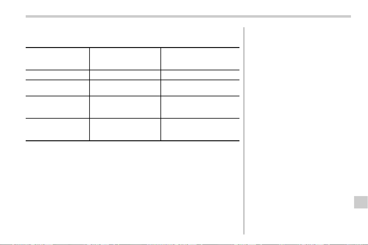
(581,1)
北米Model "A1700BE-B" EDITED: 2017/ 10/ 11
Table 1 — Occupant loading and distribution for vehicle normal load for
various designated seating capacities
Designated seating
capacity, number of
occupants
Vehicle normal load,
number of occupants
Occupant distribution in a
normally loaded vehicle
2 through 4 2 2 in front.
5 through 10 3
2 in front, 1 in second
seat.
11 through 15 5
2 in front, 1 in second
seat, 1 in third seat, 1 in
fourth seat.
16 through 22 7
2 in front, 2 in second
seat, 2 in third seat, 1 in
fourth seat.
– CONTINUED –
Consumer information and Reporting safety defects/Tire information
13-9
13
(582,1)
北米Model "A1700BE-B" EDITED: 2017/ 10/ 11
& Tire care – maintenance and
safety practices
. Check on a daily basis that the
tires are free from serious damage,
nails, and stones. At the same time,
check the tires for abnormal wear.
. Inspect the tire tread regularly
and replace the tires before their
tread wear indicators become visi-
ble. When a tire’s tread wear in-
dicator becomes visible, the tire is
worn beyond the acceptable limit
and must be replaced immediately.
With a tire in this condition, driving
at even low speeds in wet weather
can cause the vehicle to hydro-
plane. Possible resulting loss of
vehicle control can l ead to an
accident.
. Replace any damaged or un-
evenly worn tires at the time of
rotation. For information about the
tire rota tion order, refer to “
Tire
rotation” F11-36.
After tire rotation,
adjust the tire pressures and make
sure the wheel nuts are correctly
tightened. For information about
the tightening torque and tighten-
ing sequence for the wheel nuts,
refer to “
Flat tires” F9-5.
& Vehicle load limit – how to
determine
The load capacity of your vehicle is
determined by weight, not by avail-
able cargo space. The load limit of
your vehicle is shown on the vehicle
placard attached to the driver’s side
B-pillar. Locate the statement “The
combined weight of occupants and
cargo should never exceed XXX kg
or XXX lbs” on your vehicle’s
placard.
The vehicle placard also s hows
seating capacity of your vehicle.
The total load capacity includes the
total weight of driver and all pas-
sengers and their belongings, any
cargo, any optional equipment such
as a roof rack or bike carrier, etc.
Therefore cargo capacity can be
calculated by the following method.
Cargo capacity = Load limit − (total
weight of occupants + total weight
of optional equipment)
For information about vehicle load-
ing, refer to “
Loading your vehicle”
F8-11.
CAUTION
Your vehicle is neither de-
signed nor intended to be
used for trailer towing. There-
fore, never tow a trailer with
your vehicle.
Consumer information and Reporting safety defects/Tire information
13-10
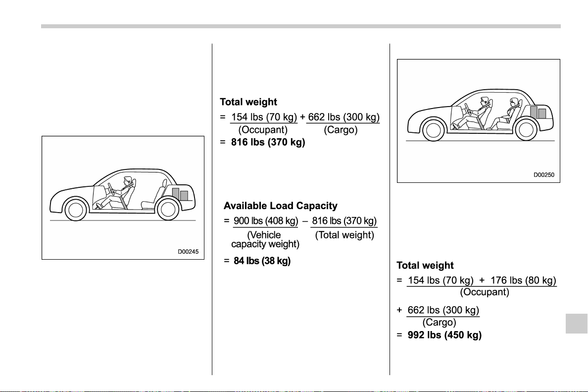
(583,1)
北米Model "A1700BE-B" EDITED: 2017/ 10/ 11
! Calculating total and load capa-
cities varying seating config-
urations
Calculate the available load capa-
city as shown in the following
examples:
Example 1A
Vehicle capacity weight of the ve-
hicle is 900 lbs (408 kg), which is
indi cated on the vehic le placard
with the statement “The combined
weight of occupants and cargo
should never exceed 900 lbs or
408 kg”.
For example, if the vehicle has one
occupant weighing 154 lbs (70 kg)
plus cargo weighing 662 lbs (300
kg).
1. Calculate the total weight.
2. Calculate the available load ca-
pacity by subtracting the total
weight from the vehicle capacity
weight of 900 lbs (408 kg).
3. The result of step 2 shows that a
further 84 lbs (38 kg) of cargo can
be carried.
Example 1B
For example, if a person weighing
176 lbs (80 kg) now enters the same
vehicle (bringing the number of
occupants to two), the calculations
are as follows.
1. Calculate the total weight.
– CONTINUED –
Consumer information and Reporting safety defects/Tire information
13-11
13
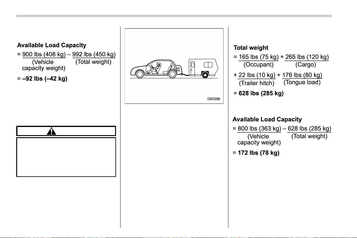
(584,1)
北米Model "A1700BE-B" EDITED: 2017/ 10/ 11
2. Calculate the available load ca-
pacity.
3. The total weight now exceeds
the capacity weight by 92 lbs (42
kg), so the cargo weight must be
reduced by 92 lbs (42 kg) or more.
Example 2A
CAUTION
Your v ehicle is neither de-
signed nor intended to be
used for trailer towing. There-
fore, never tow a trailer with
your vehicle.
Vehicle capacity weight of the ve-
hicle is 800 lbs (363 kg), which is
indicated on the vehicle placard
with the statement “The combined
weight of occupants and cargo
should never exceed 363 kg or
800 lbs”.
For example, the vehicle has one
occupant weighing 165 lbs (75 kg)
plus cargo weighing 265 lbs (120
kg). In addition, the vehicle is fitted
with a trailer hitch weighing 22 lbs
(10 kg), to which is attached a trailer
weighing 1,764 lbs (800 kg). 10% of
the trailer weight is applied to the
trailer tongue (i.e. Tongue load =
176 lbs (80 kg)).
1. Calculate the total weight.
2. Calculate the available load ca-
pacity.
3. The result of step 2 shows that a
further 172 lbs (78 kg) of cargo can
be carried.
Consumer information and Reporting safety defects/Tire information
13-12
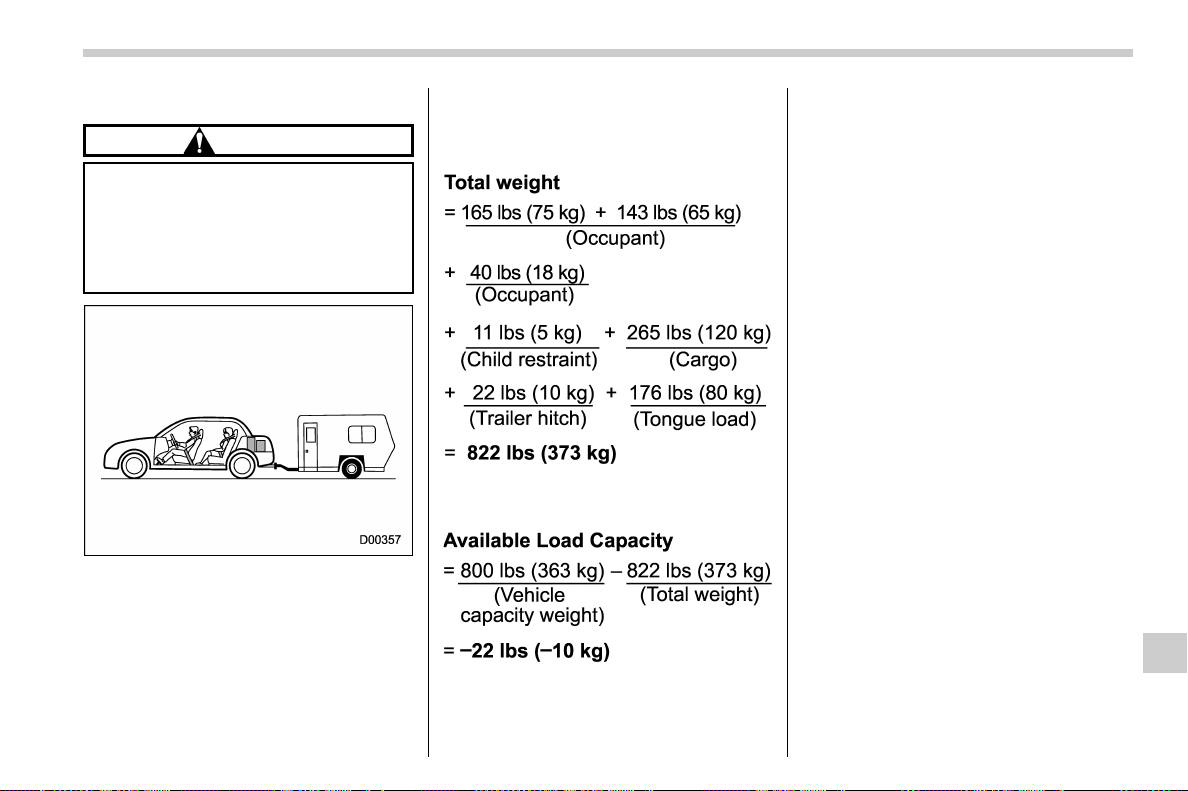
(585,1)
北米Model "A1700BE-B" EDITED: 2017/ 10/ 11
Example 2B
CAUTION
Your v ehicle is neither de-
signed nor intended to be
used for trailer towing. There-
fore, never tow a trailer with
your vehicle.
For example, if a person weighing
143 lbs (65 kg) and a child weighing
40 lbs (18 kg) now enter the same
vehicle (bringing the number of
occupants to three), and a child
restraint system weighing 11 lbs (5
kg) is installed in the vehicle for the
child to use, the calculations are as
follows:
1. Calculate the total weight.
2. Calculate the available load ca-
pacity.
3. The total weight now exceeds
the capacity weight by 22 lbs (10
kg), so the cargo weight must be
reduced by 22 lbs (10 kg) or more.
& Determining compatibility of
tire and vehicle load capaci-
ties
The sum of four tires’ maximum
load ratings must exceed the max-
imum loaded vehicle weight
(“GVWR”). In addition, sum of the
maximum load ratings of two front
tires and of two rear tires must
exceed each axle’ s maximum
loaded capacity (“GAWR”). Original
equipment tires are designed to
fulfill those conditions.
The maximum loaded vehicle
weight is referred to Gross Vehicle
Weight Rating (GVWR). And each
axle’s maximum loaded capacity is
referred to Gross Axle Weight Rat-
ing (GAWR). The GVWR and each
axle’s GAWR are shown on the
vehicle certification label affixed to
the driver’s door.
The GVWR and front and rear
GAWRs are determined by not only
the maximum load rating of tires but
– CONTINUED –
Consumer information and Reporting safety defects/Tire information
13-13
13

(586,1)
北米Model "A1700BE-B" EDITED: 2017/ 10/ 11
also loaded capacities of the vehi-
cle’s suspension, axles and other
parts of the body.
Therefore, this means that the
vehicle cannot necessarily be
loaded up to the tire’s maximum
load rating on the tire sidewall.
& Adverse safety conse-
quences of overloading on
handling and stopping and on
tires
Overloading could affect vehicle
handling, stopping distance, and
vehicle and tire performance in the
following ways. This could lead to
an accident and possibly result in
severe personal injury.
. Vehicle stability will deteriorate.
. Heavy and/or high-mounted
loads could inc rease the risk of
rollover.
. Stopping distance will increase.
. Brakes could overheat and fail.
. Suspension, bearings, axles and
other body parts could break or
experience accelerated wear that
will shorten vehicle life.
. Tires could fail.
. Tread separation could occur.
. Tire could separate from its rim.
& Steps for Determining Cor-
rect Load Limit
1. Locate the statement “The com-
bined weight of occupants and
cargo should never exceed XXX
kg or XXX lbs.” on your vehicle’s
placard.
2. Determine the combined weight
of the driver and passengers that
will be riding in your vehicle.
3. Subtract the combined weight of
the driver and passengers from
XXX kg or XXX lbs.
4. The resulting figure equals the
available amount of cargo and
luggage load capacity. For exam-
ple, if the “ XXX ” amount equals
1400 lbs. and there will be five 150
lb passengers in your vehicle, the
amount of available cargo and
luggage load capacity is 650 lbs.
(1400 − 750 (5 6 150) = 650 lbs.)
5. Determine the combined weight
of luggage and cargo being loaded
on the vehicle. That weight may not
safely exceed the available cargo
and luggage load capacity calcu-
lated in Step 4.
6. If your vehicle will be towing a
trailer, load from your trailer will be
transferred to your vehicle. Consult
this manual to determine how this
reduces the available cargo and
luggage load capacity of your ve-
hicle.
Consumer information and Reporting safety defects/Tire information
13-14
(587,1)
北米Model "A1700BE-B" EDITED: 2017/ 10/ 11
Uniform tire quality grading
standards
This information indicates the rela-
tive performance of passenger car
tires in the area of treadwear,
traction, and temperature resis-
tance. This is to aid the consumer
in making an informed choice in the
purchase of tires.
Quality grades can be found where
applicable on the tire sidewall be-
tween tread shoulder and maximum
section width. For example:
Treadwear 200 Traction AA Tem-
perature A
The quality grades apply to new
pneumatic tires for use on passen-
ger cars. However, they do not
apply to deep tread, winter type
snow tires, space-saver or tempor-
ary use spare tires, tires with
nominal rim diameters of 12 inches
or less, or to some limited produc-
tion tires.
All passenger car tires must con-
form to Federal Safety R equire-
ments in addition to these grades.
& Treadwear
The treadwear grade is a compara-
tive rating based on the wear rate of
the tire when tested under con-
trolled conditions on a specified
government test course.
For example, a tire graded 150
would wear one and one-half (1-
1/2) times as well on the govern-
ment course as a tire graded 100.
The relative performance of tires
depends upon the actual conditions
of their use, however, and may
depart significantly from the norm
due to variations in driving habits,
service practices and differences in
road characteristics and climate.
& Traction AA, A, B, C
The traction grades, from highest to
lowest, are AA, A, B and C. Those
grades represent the tire’s ability to
stop on wet pavement as measured
under controlled conditions on spe-
cified government test surfaces of
asphalt and concrete. A tire marked
C may have poor traction perfor-
mance.
WARNING
The traction grade assigned to
this tire is based on straight-
ahead braking traction tests,
and does not include accelera-
tion, cornering, hydroplaning,
or peak traction characteris-
tics.
& Temperature A, B, C
The temperature grades are A (the
highest), B, and C, representing the
tire’s resistance to the generation of
heat and its ability to dissipate heat
when tested under controlled con-
ditions on a specified indoor labora-
tory test wheel. Sustained high
temperature can cause the material
of the tire to degenerate and reduce
tire life, and excessive temperature
can lead to sudden tire failure. The
– CONTINUED –
Consumer information and Reporting safety defects/Uniform tire quality grading standards
13-15
13
(588,1)
北米Model "A1700BE-B" EDITED: 2017/ 10/ 11
grade C corresponds to a level of
performance which all passenger
car tires must meet under the
Federal Motor Vehicle Safety Stan-
dard No. 109. Grades B and A
represent higher levels of perfor-
mance on the laboratory test wheel
than the minimum required by law.
WARNING
The temperature grade for this
tire is established for a tire that
is pro perly inf lated and not
overloaded. Excessive speed,
underinflation, or excessive
loading, either separately or
in combination, can ca use
heat buildup and possible tire
failure.
Reporting safety defects
(U.S.A.)
If you believe that your vehicle has
a defect which could cause a crash
or could cause injury or death, you
should immediately inform the Na-
tional Highway Traffic Safety Ad-
ministration (NHTSA) in addition to
notifying Subaru of America, Inc.
If NHTSA receives similar com-
plaints, it may open an investiga-
tion, and if it finds that a safety
defect exists in a group of vehicles,
it may order a recall and remedy
campaign. However, NHTSA can-
not become involved in individual
problems between you, your deal-
er, or Subaru of America, Inc. To
contact NHTSA, you may call the
Vehicle Safety Hotline toll-free at
1-888-327-4236 (TTY: 1-800-424-
9153); go to http://www.safercar.
gov; or write to: Admini strator,
NHTSA, 1200 New Jersey Ave-
nue, SE, West Building, Washing-
ton, DC 20590. You can also
obtain other information about mo-
tor vehicle safety from http://www.
safercar.gov.
Consumer information and Reporting safety defects/Reporting safety defects (U.S.A.)
13-16

(1,1)
北米Model "A1700BE-B" EDITED: 2017/ 10/ 11
Index
14

(2,1)
北米Model "A1700BE-B" EDITED: 2017/ 10/ 11
14-2 Index
A
Abbreviation ................................................................... 3
ABS (Anti-lock Brake System) ..................................... 7-35
Warning light ......................................................... 3-20
Access key fob ............................................................ 2-8
Warning light ................................................. 3-28, 3-29
Accessories ............................................................. 11-44
Accessory power outlet ................................................ 6-8
Air cleaner element ................................................... 11-18
Air conditioner
Automatic climate control.......................................... 4-5
Manual climate control.............................................. 4-6
Air flow mode .............................................................. 4-6
All-Wheel Drive warning light....................................... 3-25
Alloy wheel .............................................................. 11-38
Cleaning ............................................................... 10-4
Antenna
Roof antenna (for Shark fin type)............................... 5-2
Anti-lock Brake System (ABS) ..................................... 7-35
Armrest .................................................................... 1-12
Ashtray..................................................................... 6-10
AT OIL TEMP warning light ......................................... 3-18
Audio
aha
TM
by HARMAN................................................ 5-42
AM/FM radio ......................................................... 5-27
Antenna system....................................................... 5-2
AUX ..................................................................... 5-59
Base display audio set ............................................. 5-3
Basic operation...................................................... 5-17
Bluetooth audio ..................................................... 5-56
CD ....................................................................... 5-51
iPod...................................................................... 5-54
Pandora
®
.............................................................. 5-48
SiriusXM Satellite Radio.......................................... 5-36
STARLINK
TM
7.0 Multimedia Plus audio set ............... 5-5
Steering switches for audio ..................................... 5-61
SUBARU STARLINK............................................... 5-25
Unit setting ............................................................ 5-18
USB memory ......................................................... 5-53
Auto dimmer cancel function........................................ 3-71
Auto Vehicle Hold function
ON indicator light ................................................... 3-24
Operation indicator light .......................................... 3-24
Auto-dimming mirror/compass............................. 3-75, 3-76
Automatic headlight beam leveler................................. 3-71
Warning light ......................................................... 3-35
Automatic Locking Retractor/Emergency Locking
Retractor (ALR/ELR)................................................ 1-13
Automatic transmission
Oil temperature warning light (AT OIL TEMP) ............ 3-18
B
Battery .................................................................... 11-41
Drainage prevention function .................................... 2-6
Jump starting......................................................... 9-17
Replacement (access key fob) ............................... 11-52
Replacement (keyless access with push-button
start system).............................................. 2-16, 11-52
Replacement (remote keyless entry system).... 2-21, 11-53
Replacement (transmitter) ..................................... 11-53
Bluetooth
®
Audio .................................................................... 5-56

(3,1)
北米Model "A1700BE-B" EDITED: 2017/ 10/ 11
Hands-free phone system....................................... 5-69
Bluetooth
®
settings .................................................... 5-64
Registering/connecting Bluetooth
®
device ................. 5-64
Setting Bluetooth details ......................................... 5-67
Booster seat.............................................................. 1-29
Bottle holder................................................................ 6-8
Brake
Assist ................................................................... 7-33
Booster....................................................... 7-33, 11-26
Disc ..................................................................... 12-9
Fluid........................................................... 11-24, 12-7
Pad ..................................................................... 11-29
Parking............................................... 7-42, 7-43, 11-30
Pedal .................................................................. 11-27
System ................................................................. 7-33
Brake pedal
Free play ............................................................. 11-27
Reserve distance.................................................. 11-27
Brake system ............................................................ 7-33
Warning light ......................................................... 3-21
Braking..................................................................... 7-33
Tips...................................................................... 7-33
Breaking-in of new brake pads ................................... 11-29
BSD/RCTA................................................................ 7-57
BSD/RCTA approach indicator light/warning buzzer ... 7-60
BSD/RCTA OFF switch........................................... 7-63
BSD/RCTA warning indicator................................... 7-62
Bulb
Chart.................................................................. 12-14
Replacing ............................................................ 11-44
C
Catalytic converter....................................................... 8-3
Center
Console ................................................................. 6-5
Changing
Coolant ............................................................... 11-18
Flat tire .................................................................. 9-5
Oil and oil filter..................................................... 11-15
Charge warning light................................................... 3-17
CHECK ENGINE warning light/Malfunction indicator
light ....................................................................... 3-16
Checking
Brake pedal free play............................................ 11-27
Brake pedal reserve distance................................. 11-27
Clutch function..................................................... 11-27
Clutch pedal free play ........................................... 11-28
Coolant level........................................................ 11-17
Fluid level (brake fluid).......................................... 11-24
Fluid level (clutch fluid) ......................................... 11-25
Fluid level (power steering fluid)............................. 11-23
Fluid level (washer fluid) ....................................... 11-38
Oil level (engine oil).............................................. 11-13
Child restraint systems................................................ 1-21
Installation of a booster seat.................................... 1-29
Installation with ALR/ELR seatbelt............................ 1-25
Lower and tether anchorages .................................. 1-30
Top tether anchorages ............................................ 1-32
Child safety ................................................................... 5
Locks.................................................................... 2-31
Chime
Light ..................................................................... 3-63
Index 14-3

(4,1)
北米Model "A1700BE-B" EDITED: 2017/ 10/ 11
14-4 Index
Seatbelt ................................................................ 3-14
Cigarette lighter ........................................................... 6-9
Cleaning
Alloy wheels.......................................................... 10-4
Interior.................................................................. 10-6
Steering wheel with ultra-suede covering.................. 10-7
Ventilation grille ....................................................... 4-9
Climate control system ................................................. 4-3
Automatic ............................................................... 4-5
Manual ................................................................... 4-6
Clock........................................................................ 3-44
Clutch
Fluid........................................................... 11-25, 12-7
Pedal .................................................................. 11-27
Coat hook................................................................. 6-11
Combination meter display (color LCD) ........................ 3-38
Compass .......................................................... 3-75, 3-76
Console ...................................................................... 6-5
Continuously variable transmission (CVT)..................... 7-23
Fluid.................................................................... 11-22
Coolant........................................................... 11-17, 12-7
Cooling system......................................................... 11-16
Corrosion protection................................................... 10-5
Cruise control............................................................ 7-53
Indicator light......................................................... 3-35
Set indicator light................................................... 3-35
Cup holder.................................................................. 6-6
Front passenger’s .................................................... 6-6
Rear passenger’s .................................................... 6-7
D
Daytime running light system ....................................... 3-69
Defogger ................................................................... 3-84
Defrosting................................................................... 4-9
Deicer....................................................................... 3-84
Differential gear oil
Front........................................................... 11-23, 12-6
Rear ........................................................... 11-23, 12-6
Dimensions ............................................................... 12-2
Disc brake pad wear warning indicators........................ 7-34
Dome light.................................................................. 6-2
Door
Locks..................................................................... 2-4
Open warning light ................................................. 3-24
Double trip meter ........................................................ 3-9
Drive belts............................................................... 11-21
Driver’s Control Center Differential ............................... 7-18
Auto indicator light.................................................. 3-36
Indicator light ......................................................... 3-36
Driving
All-Wheel Drive warning light ................................... 3-25
AWD vehicles ......................................................... 8-5
Car phone/cell phone.................................................. 8
Drinking .................................................................... 6
Drugs........................................................................ 7
Foreign countries .................................................... 8-4
Pets.......................................................................... 8
Snowy and icy roads ............................................... 8-8
Tips ................................................ 7-18, 7-28, 8-2, 8-5
Tired or sleepy ........................................................... 7
Winter.................................................................... 8-6

(5,1)
北米Model "A1700BE-B" EDITED: 2017/ 10/ 11
E
ECO gauge............................................................... 3-12
Electrical system........................................................ 12-8
Electronic Brake Force Distribution (EBD)
system .......................................................... 3-22, 7-36
Electronic parking brake ............................................. 7-43
Automatic release function by accelerator pedal ........ 7-45
Warning........................................................ 3-22, 7-45
Emergency Locking Retractor (ELR) ............................ 1-13
Engine
Compartment overview.......................................... 11-11
Coolant....................................................... 11-17, 12-7
Exhaust gas (carbon monoxide) ............................ 6, 8-2
Hood .................................................................... 11-9
Low oil level warning light ....................................... 3-17
Oil.............................................................. 11-13, 12-4
Overheating .......................................................... 9-20
Starting & stopping .................................................. 7-9
Event data recorder ........................................................ 9
Exterior care ............................................................. 10-2
F
Flat tire repair kit ....................................................... 9-11
Technical data ....................................................... 9-16
Flat tires ..................................................................... 9-5
Floor mat .................................................................. 6-11
Fluid level
Brake .................................................................. 11-24
Clutch.................................................................. 11-25
Continuously variable transmission ......................... 11-22
Power steering ..................................................... 11-23
Fog light.................................................................... 3-72
Bulb.......................................................... 11-49, 12-14
Indicator light ......................................................... 3-35
Switch................................................................... 3-72
Front
Differential gear oil ....................................... 11-23, 12-6
Fog light...................................................... 3-72, 11-49
Fog light indicator light............................................ 3-35
Seatbelt pretensioners ............................................ 1-17
Front fog light ............................................................ 3-72
Switch................................................................... 3-72
Front seats ................................................................. 1-2
Forward and backward adjustment ............................ 1-4
Head restraint adjustment ........................................ 1-5
Power seat ............................................................. 1-5
Reclining ................................................................ 1-4
Seat height adjustment (driver’s seat) ........................ 1-4
Fuel........................................................................... 7-3
Consumption indicator ................................... 3-47, 3-48
Economy hints ........................................................ 8-2
Filler lid and cap ..................................................... 7-5
Gauge................................................................... 3-10
Requirements ................................................. 7-3, 12-3
Fuses ..................................................................... 11-42
Fuses and circuits .................................................... 12-10
G
GAWR (Gross Axle Weight Rating) .............................. 8-12
Glove box................................................................... 6-5
GVWR (Gross Vehicle Weight Rating) .......................... 8-12
Index 14-5

(6,1)
北米Model "A1700BE-B" EDITED: 2017/ 10/ 11
14-6 Index
H
Hands-free phone system........................................... 5-69
Hazard warning flasher.......................................... 3-8, 9-2
Head restraint adjustment
Front seat ............................................................... 1-5
Rear seat................................................................ 1-8
Headlight
Beam leveler......................................................... 3-71
Bulb replacement.................................................. 11-44
Bulb replacing ...................................................... 11-44
Bulb wattage ....................................................... 12-14
Control switch ....................................................... 3-63
Flasher ................................................................. 3-68
Indicator light......................................................... 3-35
OFF delay function ................................................ 3-64
OFF delay setting .................................................. 3-64
Welcome lighting function ....................................... 3-64
High beam assist function........................................... 3-65
Indicator light......................................................... 3-35
Warning indicator................................................... 3-35
High beam assist warning indicator.............................. 3-35
High beam indicator light ............................................ 3-35
High/low beam change (dimmer) ................................. 3-65
Hill start assist................................................. 7-49, 11-28
OFF indicator light ................................................. 3-24
To activate/deactivate ............................................. 7-51
Warning light ......................................................... 3-24
HomeLink
®
................................................................ 3-76
Hook
Coat..................................................................... 6-11
Towing and tie-down .............................................. 9-21
Horn ......................................................................... 3-86
Hose and connections .............................................. 11-17
I
Ignition switch ............................................................. 3-4
Illumination brightness control ...................................... 3-71
Immobilizer
Indicator light (security indicator light) ....................... 3-33
Indicator light
Auto Vehicle Hold ON............................................. 3-24
Auto Vehicle Hold operation .................................... 3-24
BSD/RCTA OFF..................................................... 3-37
BSD/RCTA warning ................................................ 3-37
Cruise control ........................................................ 3-35
Cruise control set ................................................... 3-35
Driver’s Control Center Differential ........................... 3-36
Driver’s Control Center Differential Auto.................... 3-36
Front fog light ........................................................ 3-35
Headlight............................................................... 3-35
High beam............................................................. 3-35
High beam assist ................................................... 3-35
High beam assist warning ....................................... 3-35
Hill start assist OFF ................................................ 3-24
Immobilizer............................................................ 3-33
REV ..................................................................... 3-37
Security................................................................. 3-33
Select lever/Gear position ....................................... 3-34
Shift-up ................................................................. 3-34
SI-DRIVE .............................................................. 3-34
Traction control OFF............................................... 3-27
Turn signal ............................................................ 3-35

(7,1)
北米Model "A1700BE-B" EDITED: 2017/ 10/ 11
Vehicle Dynamics Control OFF................................ 3-27
Vehicle Dynamics Control operation................. 3-25, 3-27
Inside mirror.............................................................. 3-75
Interior lights ............................................................... 6-2
Internal trunk lid release handle................................... 2-37
J
Jack-up point............................................................... 9-5
Jump starting ............................................................ 9-17
K
Key ............................................................................ 2-2
Number .................................................................. 2-3
Keyless access with push-button start system................. 2-8
Disabling keyless access functions .......................... 2-14
Locking and unlocking doors ................................... 2-11
Opening trunk ....................................................... 2-11
Warning chimes and warning light ................... 2-14, 3-28
When access key does not operate properly............. 2-16
When access key fob does not operate properly ....... 9-26
L
Leather seat materials ................................................ 10-6
LED headlights......................................................... 11-44
License plate light..................................................... 11-50
Light
Control switch ....................................................... 3-63
Daytime running .................................................... 3-69
Dome ..................................................................... 6-2
Front fog..................................................... 3-72, 11-49
Front position ................................................ 3-64, 3-72
Front side marker ................................................. 12-14
License plate ....................................................... 11-50
Map....................................................................... 6-2
Rear combination ................................................. 11-49
Rear side marker light........................................... 11-49
Stop light............................................................. 11-49
Tail light .............................................................. 11-49
Turn signal .................................................. 3-70, 11-49
Limited slip differential (LSD) ....................................... 7-31
Loading your vehicle................................................... 8-11
Low fuel warning light ................................................. 3-24
Low tire pressure warning light .................................... 3-19
Lower and tether anchorage ........................................ 1-30
LSD (Limited slip differential) ....................................... 7-31
M
Maintenance
Precautions ........................................................... 11-3
Schedule............................................................... 11-3
Seatbelt ................................................................ 1-17
Tips ...................................................................... 11-6
Tools...................................................................... 9-3
Malfunction indicator light (check engine warning light) ... 3-16
Manual
Climate control.................................................. 4-5, 4-6
Mode (continuously variable transmission) ................ 7-25
Seat ...................................................................... 1-4
Transmission ......................................................... 7-16
Transmission oil ........................................... 11-22, 12-6
Map light .................................................................... 6-2
Meters and gauges...................................................... 3-8
Index 14-7

(8,1)
北米Model "A1700BE-B" EDITED: 2017/ 10/ 11
14-8 Index
Mirror defogger.......................................................... 3-84
Mirrors...................................................................... 3-75
Moonroof .......................................................... 2-38, 9-28
Multi-function display (color LCD) ................................ 3-44
N
New vehicle break-in driving ......................................... 8-2
O
Odometer ................................................................... 3-9
Oil filter.................................................................... 11-15
Oil level
Engine................................................................. 11-13
Front differential gear ............................................ 11-23
Manual transmission ............................................. 11-22
Rear differential gear............................................. 11-23
Warning light ......................................................... 3-17
Oil pressure warning light ........................................... 3-17
Outside
Mirror defogger...................................................... 3-84
Mirrors.................................................................. 3-83
Overheating engine.................................................... 9-20
P
Parking
Brake ........................................................... 7-42, 7-43
Brake stroke......................................................... 11-30
Tips...................................................................... 7-45
Periodic inspections ..................................................... 8-4
Petrol fuel ................................................................... 7-3
PIN code Access ....................................................... 2-12
Power
Door locking switch ................................................. 2-7
Outlets ................................................................... 6-8
Outside mirrors ............................................. 3-83, 3-84
Seat ...................................................................... 1-5
Steering ................................................................ 7-31
Steering fluid ............................................... 11-23, 12-7
Steering warning light ............................................. 3-25
Precautions against vehicle modification .............. 1-21, 1-64
Preparing to drive........................................................ 7-8
Push-button
Ignition switch ......................................................... 3-4
Starting and stopping engine .................................... 7-9
R
Rear
Combination lights................................................ 11-49
Differential gear oil ....................................... 11-23, 12-6
Limited slip differential ............................................ 7-31
Turn signal light ................................................... 11-49
Rear differential
Oil temperature warning light ................................... 3-18
Rear seat ................................................................... 1-8
Armrest ................................................................. 1-12
Folding down ......................................................... 1-10
Head restraint adjustment ........................................ 1-8
Rear view camera ...................................................... 6-13
How to adjust the rear view image ........................... 5-24
Rear window
Defogger ............................................................... 3-84
Rear wing.................................................................. 8-15

(9,1)
北米Model "A1700BE-B" EDITED: 2017/ 10/ 11
Recommended
Brake fluid ............................................................ 12-7
Clutch fluid.................................................. 11-25, 12-7
Engine oil ............................................................. 12-4
Front differential gear oil ......................................... 12-6
Manual transmission oil .......................................... 12-6
Power steering fluid ............................................... 12-7
Rear differential gear oil ......................................... 12-6
Spark plugs........................................................... 12-8
Refueling .................................................................... 7-5
Remote keyless entry system...................................... 2-18
Replacement
Access key fob battery .......................................... 11-52
Brake pad and lining ............................................. 11-28
Wiper blades........................................................ 11-39
Replacing
Access key fob battery .......................................... 11-52
Air cleaner element ............................................... 11-19
Battery of access key fob ...................................... 11-52
Lost transmitters (remote keyless entry system) ........ 2-21
Remote keyless entry transmitter battery ................. 11-53
Replacing bulbs.............................................. 11-44, 12-14
Front fog light ....................................................... 11-49
Front side marker light........................................... 11-47
Front turn signal light .................................. 11-47, 11-48
Headlight ............................................................. 11-44
LED headlight ...................................................... 11-44
License plate light................................................. 11-50
Parking light ......................................................... 11-47
Rear combination light........................................... 11-49
Rear side marker light ........................................... 11-49
Rear turn signal light ............................................ 11-49
REV indicator light and buzzer..................................... 3-12
Reverse Automatic Braking System.............................. 7-66
Rocking the vehicle .................................................... 8-10
Roof molding and crossbar.......................................... 8-13
S
Safety
Precautions when driving ............................................ 4
Symbol ..................................................................... 3
Warnings................................................................... 2
Sealing flat tire............................................................ 9-8
Flat tire repair kit .................................................... 9-11
How to seal ........................................................... 9-12
Safety precautions................................................... 9-9
Seat
Fabric ................................................................... 10-6
Front...................................................................... 1-2
Heater.................................................................... 1-7
Height adjustment ................................................... 1-4
Power .................................................................... 1-5
Rear ...................................................................... 1-8
Seatbelt ................................................................ 4, 1-12
Fastening .............................................................. 1-14
Maintenance .......................................................... 1-17
Pretensioners ........................................................ 1-17
Safety tips ............................................................. 1-12
Warning light and chime.......................................... 3-14
Security
Indicator light ......................................................... 3-33
Index 14-9

(10,1)
北米Model "A1700BE-B" EDITED: 2017/ 10/ 11
14-10 Index
Select lever
Position indicator ................................................... 3-34
Shift lock function .................................................. 7-27
Shift-up indicator light................................................. 3-34
SI-DRIVE
Indicator light......................................................... 3-34
SI-DRIVE mode......................................................... 7-28
Snow tires......................................................... 8-9, 11-30
Snowy and icy roads.................................................... 8-8
Sounding a panic alarm.............................................. 2-20
Spark plugs..................................................... 11-21, 12-8
Specifications ............................................................ 12-2
Speedometer............................................................... 3-9
SRS airbag
(Supplemental Restraint System airbag) ................ 4, 1-33
SRS airbag system
Monitors ............................................................... 1-62
Servicing .............................................................. 1-63
Warning light ......................................................... 3-15
Starting & stopping engine ............................................ 7-9
State emission testing (U.S. only) .................................. 7-7
Steering Responsive Headlight.................................... 3-69
Steering switches for audio ......................................... 5-61
Steering wheel
Power................................................................... 7-31
Tilt/telescopic ........................................................ 3-85
Stop light ................................................................. 11-49
Storage compartment................................................... 6-5
Sun shade ................................................................ 2-40
Sun visors................................................................... 6-3
Supplemental Restraint System airbag (SRS) ............... 1-33
Synthetic leather upholstery......................................... 10-6
T
Tachometer ............................................................... 3-10
Temperature gauge .................................................... 3-11
Temperature warning light
AT OIL TEMP ........................................................ 3-18
Rear differential oil ................................................. 3-18
Temporary spare tire............................................ 9-2, 12-9
Tether (child restraint system) ............................. 1-30, 1-32
Tie-down hooks.......................................................... 9-21
Tire................................................................. 11-30, 12-8
Chains .................................................................. 8-10
Inspection............................................................ 11-32
Pressures and wear.............................................. 11-32
Replacement ....................................................... 11-36
Rotation .............................................................. 11-36
Size and pressure .................................................. 12-8
Types.................................................................. 11-30
Tire pressure monitoring system (TPMS) .... 7-40, 9-16, 11-30
Warning light ......................................................... 3-19
Tires and wheels ...................................................... 11-30
Tools.......................................................................... 9-3
Top tether anchorages ....................................... 1-30, 1-32
Towing ...................................................................... 9-21
All wheels on the ground......................................... 9-25
Flat-bed truck ........................................................ 9-24
Hooks ................................................................... 9-21
Trailer
Towing .................................................................. 8-14
Trip meter................................................................... 3-9

(11,1)
北米Model "A1700BE-B" EDITED: 2017/ 10/ 11
Trunk lid ................................................................... 2-36
Release handle ..................................................... 2-37
Turn signal
Indicator lights ....................................................... 3-35
Lever.................................................................... 3-70
U
Under-floor storage compartment................................. 6-12
V
Vanity mirror................................................................ 6-4
Vehicle
Capacity weight ..................................................... 8-12
Identification........................................................ 12-16
Symbols .................................................................... 4
Vehicle Dynamics Control
OFF indicator light ................................................. 3-27
OFF switch ........................................................... 7-39
Operation indicator light.................................. 3-25, 3-27
System ................................................................. 7-37
Warning light ......................................................... 3-26
Ventilator .................................................................... 4-2
Voice command system operation ............................... 5-79
W
Warning and indicator lights ........................................ 3-13
Warning chimes
Keyless access with push-button start system........... 3-28
Warning light
ABS ..................................................................... 3-20
Access key ................................................... 3-28, 3-29
All-Wheel Drive ...................................................... 3-25
AT OIL TEMP ........................................................ 3-18
Automatic headlight beam leveler............................. 3-35
Brake system......................................................... 3-21
Charge.................................................................. 3-17
CHECK ENGINE.................................................... 3-16
Door open ............................................................. 3-24
Driver’s Control Center Differential ........................... 3-37
Engine low oil level................................................. 3-17
High Beam Assist................................................... 3-35
High Beam Assist warning....................................... 3-35
Hill start assist ....................................................... 3-24
Keyless access with push-button start system ........... 3-28
Low fuel ................................................................ 3-24
Low tire pressure ................................................... 3-19
Oil pressure........................................................... 3-17
Power steering....................................................... 3-25
Rear differential oil temperature ............................... 3-18
Seatbelt ................................................................ 3-14
SRS airbag system................................................. 3-15
Steering Responsive Headlight ................................ 3-37
Vehicle Dynamics Control........................................ 3-26
Windshield washer fluid .......................................... 3-18
Warranties..................................................................... 1
Washing.................................................................... 10-2
Waxing and polishing.................................................. 10-4
Wear indicators........................................................ 11-35
Welcome lighting function............................................ 3-64
What to do if... ........................................................... 5-87
Troubleshooting ..................................................... 5-87
Index 14-11

(12,1)
北米Model "A1700BE-B" EDITED: 2017/ 10/ 11
14-12 Index
Wheel
Alloy.................................................................... 11-38
Balance ............................................................... 11-34
Nut tightening torque............................... 9-5, 12-8, 12-9
Replacement........................................................ 11-37
Windows................................................................... 2-31
Windshield
Washer fluid......................................................... 11-38
Wiper and washer switches .................................... 3-74
Wiper blades........................................................ 11-40
Wiper deicer.......................................................... 3-84
Winter
Driving.................................................................... 8-6
Tires............................................................. 8-9, 11-30
Wiper and washer...................................................... 3-72
Wiper deicer.............................................................. 3-84

Black plate (1,1)
Model "ALL_MODEL_MEMO" EDITED: 2007/ 6/ 22
Right Page
————————————————————————————————————————
————————————————————————————————————————
————————————————————————————————————————
————————————————————————————————————————
————————————————————————————————————————
————————————————————————————————————————
————————————————————————————————————————
————————————————————————————————————————
————————————————————————————————————————
————————————————————————————————————————
————————————————————————————————————————
————————————————————————————————————————
————————————————————————————————————————

Black plate (2,1)
Model "ALL_MODEL_MEMO" EDITED: 2007/ 6/ 22
Left Page
————————————————————————————————————————
————————————————————————————————————————
————————————————————————————————————————
————————————————————————————————————————
————————————————————————————————————————
————————————————————————————————————————
————————————————————————————————————————
————————————————————————————————————————
————————————————————————————————————————
————————————————————————————————————————
————————————————————————————————————————
————————————————————————————————————————
————————————————————————————————————————

(2,1)
北米Model "A1700BE-B" EDITED: 2017/ 9/ 12
GAS STATION REFERENCE
S99AA
& Fuel:
S99AA01
! STI
S99AA0106
The engine is designed to operate at maximum performance
using unleaded gasoline with an octane rating of 93 AKI (98
RON) or higher. If 93 AKI (98 RON) fuel is not readily available
in your area, unleaded gasoline with an octane rating of 91 AKI
(95 RON) may be used with no detriment to engine durability or
driveability. However, you may notice a slight decrease in
maximum engine performance while using 91 AKI (95 RON)
fuel. Use of 91 AKI (95 RON) fuel will not affect your warranty
coverage.
! Except STI
S99AA0108
Use unleaded gasoline with an octane rating of 91 AKI (95
RON) or higher. If 91 AKI (95 RON) fuel is not readily available,
unleaded gasoline with an octane rating of 87 AKI (90 RON) may
be used.
& Fuel octane rating:
S99AA02
! AKI
S99AA0202
This octane rating is the average of the Research Octane and
Motor Octane numbers and is commonly referred to as the Anti
Knock Index (AKI).
! RON
S99AA0201
This octane rating is the Research Octane Number.
& Fuel tank capacity:
S99AA03
15.9 US gal (60 liters, 13.2 Imp gal)
& Engine oil:
S99AA04
Use only the following oils.
. ILSAC GF-5, which can be identified with the ILSAC
certification mark (Starburst mark)
. or API classification SN with the words “RESOURCE
CONSERVING”
For the complete viscosity requirements, refer to “Engine oil”
F12-4.
& Engine oil capacity:
S99AA05
! STI
S99AA0501
4.5 US qt (4.3 liters, 3.8 Imp qt)
! Except STI
S99AA0502
5.4 US qt (5.1 liters, 4.5 Imp qt)
The indicated oil quantity is only a guideline and is estimated
based on a case when the engine oil is changed with an oil filter.
Check the oil level using an oil level gauge after refilling the
engine with oil. For more details about maintenance and
service, refer to “Engine oil” F11-13.
& Cold tire pressure:
S99AA06
Refer to “Tires” F12-8.