Loading ...
Loading ...
Loading ...
7
When a standard 2-prong wall outlet is encountered, it is your responsibility and obligation to have it
replaced with a properly grounded 3-prong wall outlet.
To prevent accidental injury, the cord should be secured behind the appliance and not left exposed or
dangling.
The appliance should always be plugged into its own individual electrical outlet that has a voltage rating
that matches the rating label on the appliance. This provides the best performance and also prevents
overloading house wiring circuits that could cause a fire hazard from overheating. Never unplug the
appliance by pulling on the power cord. Always grip the plug firmly and pull straight out from the
receptacle. Repair or replace immediately all power cords that have become frayed or otherwise
damaged. Do not use a cord that shows cracks or abrasion damage along its length or at either end.
When moving the appliance, be careful not to damage the power cord.
EXTENSION CORD
Because of potential safety hazards under certain conditions, it is strongly recommended that you do not
use an extension cord with this appliance. However, if you must use an extension cord it is absolutely
necessary that it be a UL/CUL-Listed, 3-wire grounding type appliance extension cord having a grounding
type plug and outlet and that the electrical rating of the cord be 115 volts and at least 10 amperes.
ADJUSTING THE HEIGHT OF THE UNIT
The height of the unit can be increased by up to 3” by turning the adjustable legs. Once the desired height
has been achieved, the gap between the kick-plate and the floor can be covered by inserting a kick-plate
extender, which is described in the next section.
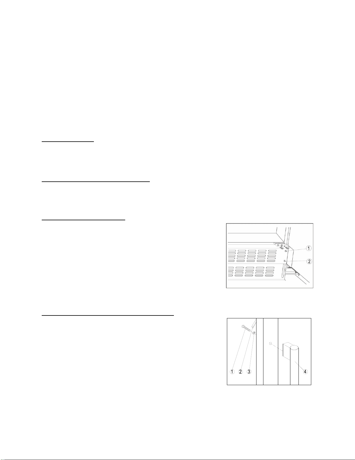
ADJUSTING THE KICK-PLATE
This appliance includes an adjustable kick-plate extender that is not
required to operate the unit. In order to adjust the kick-plate height,
follow the instructions below:
1. Remove the screws (2) from both the bottom left- and bottom
right-hand sides of the kick-plate installed on the unit.
2. Loosen the screws (1) from both the top left- and top right-hand
sides of the kick-plate installed on the unit.
3. Carefully insert the kick-plate extender under the kick-plate until
the desired height is achieved.
4. Reinsert screws and tighten them.
INSTALLING THE STAINLESS STEEL HANDLES
This appliance includes two stainless steel handle that are not
required to operate the unit. To install each handle, follow the
instructions below:
1. Remove the door gasket (2) on the side you wish to install the
handle - you can see two designated holes for handle
installation.
2. Install the handle (4) tightly as shown here with two screws (1)
and flat washers (3) provided.
3. Replace the door gasket.
Loading ...
Loading ...
Loading ...