Technician’s Handbook Ice Machine
Maintenance
Detailed Cleaning and Sanitizing
General
- You are responsible for maintaining the ice machine in accordance with the instructions in this manual. Maintenance procedures are not covered by the warranty.
- Descale and sanitize the ice machine a minimum of once every six months for efficient operation. If the ice machine requires more frequent descaling and sanitizing, consult a qualified service company to test the water quality and recommend appropriate water treatment. An extremely dirty ice machine must be taken apart for descaling and sanitizing.
- Manitowoc Ice Machine Cleaner/Descaler and Sanitizer are the only products approved for use in Manitowoc ice machines.
Caution: Use only Manitowoc approved Ice Machine Cleaner/ Descaler and Sanitizer for this application (Manitowoc Cleaner/Descaler part number 9405463 and Manitowoc Sanitizer part number 9405653). It is a violation of Federal law to use these solutions in a manner inconsistent with their labeling. Read and understand all labels printed on bottles before use.
Caution: Do not mix Cleaner/Descaler and Sanitizer solutions together. It is a violation of Federal law to use these solutions in a manner inconsistent with their labeling.
Warning: Wear rubber gloves and safety goggles (and/or face shield) when handling Ice Machine Cleaner/Descaler or Sanitizer.
Detailed Descaling/Sanitizing Procedure
This procedure must be performed a minimum of once every six months.
- The ice machine and bin must be disassembled descaled and sanitized.
- All ice produced during the descaling and sanitizing procedures must be discarded.
- Removes mineral deposits from areas or surfaces that are in direct contact with water.
Remedial Cleaning Procedure
- This procedure descales all components in the water flow path, and is used to clean the ice machine between the bi-yearly detailed descaling/sanitizing procedure.
IAUCS®
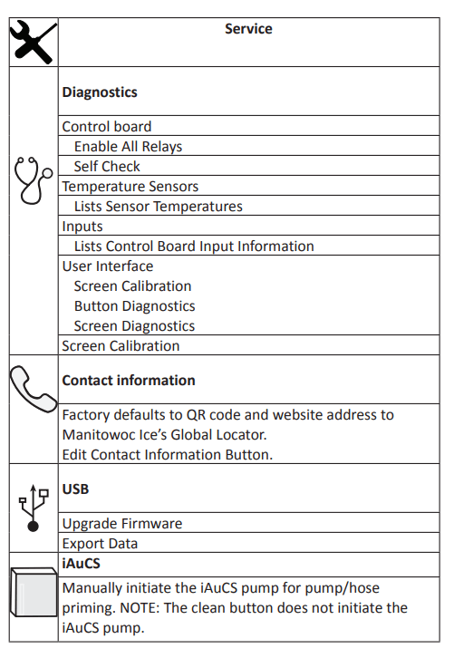
- iAuCS® does not operate when the Clean button is used to start a clean cycle. To prime the hose, activation is required through the Service Menu/iAuCS® icon.
Exterior Cleaning
- Clean the area around the ice machine as often as necessary to maintain cleanliness and efficient operation.
- Wipe surfaces with a damp cloth rinsed in water to remove dust and dirt from the outside of the ice machine. If a greasy residue persists, use a damp cloth rinsed in a mild dish soap and water solution. Wipe dry with a clean, soft cloth.
- The exterior panels have a clear coating that is stain resistant and easy to clean. Products containing abrasives will damage the coating and scratch the panels.
- Never use steel wool or abrasive pads for cleaning.
- Never use chlorinated, citrus based or abrasive cleaners on exterior panels and plastic trim pieces
Touchscreen Operation For The Clean Cycle
- STARTING A CLEAN CYCLE: Pressing the clean icon will display a Continue/Abort screen, and a warning that pressing Continue will result in a clean cycle that can last up to 35 minutes.
- WATER CURTAIN/DAMPER OPERATION DURING THE CLEAN CYCLE: The water curtain/damper must remain closed during the clean sequence. When the curtain/damper is open for more than 3 seconds the clean cycle stops and a message is displayed on the touchscreen with a choice to continue or stop the clean cycle. Stopping the clean cycle will result in a series of rinse and dump cycles to verify cleaner or sanitizer has been removed before ice making.
- PAUSING A CLEAN CYCLE: The clean cycle can be paused and resumed at any time by pressing the on/off button. The clean cycle will resume from the beginning of either the wash or rinse cycle depending on the point of interruption.
- POWER INTERRUPTION DURING CLEAN CYCLE: If the power supply is interrupted during the clean cycle the state is retained in the circuit board. When power is reapplied the clean cycle will resume from the beginning of either the wash or rinse cycle depending on the point of interruption.
- ABORTING A CLEAN CYCLE: Verify cleaner/descaler or sanitizer is not present in the water system before aborting a clean cycle.
- Press and hold the Clean button, then press and release the On/Off button.
- Release the Clean button and select abort from the touchscreen.
Detailed Descaling/Sanitizing Procedure
- Caution: Use only Manitowoc approved Ice Machine Cleaner/ Descaler and Sanitizer for this application (Manitowoc Cleaner/Descaler part number 9405463 and Manitowoc Sanitizer part number 9405653). It is a violation of Federal law to use these solutions in a manner inconsistent with their labeling. Read and understand all labels printed on bottles before use.
CLEANING PROCEDURE
Caution: Do not mix Cleaner/Descaler and Sanitizer solutions together. It is a violation of Federal law to use these solutions in a manner inconsistent with their labeling.
Warning: Wear rubber gloves and safety goggles (and/or face shield) when handling Ice Machine Cleaner or Sanitizer.
Ice machine cleaner/descaler is used to remove lime scale and mineral deposits. Ice machine sanitizer disinfects and removes algae and slime.
NOTE: Although not required and dependent on your installation, removing the ice machine top cover may allow easier access.
Step 1 Open the front door to access the evaporator compartment. Ice must not be on the evaporator during the clean/sanitize cycle. Follow one of the methods below:
- Press the power switch at the end of a harvest cycle after ice falls from the evaporator(s).
- Press the power switch and allow the ice to melt
- Use the touchscreen to initiate a manual harvest cycle.
Step 2 Remove all ice from the bin/dispenser.
Step 3 Press the Clean button and select “Turn off when complete”. Water will flow through the water dump valve and down the drain. Wait approximately 1 minute until the water trough refills and the display indicates Add Chemical. Add the proper amount of ice machine cleaner/ descaler to the water trough by pouring between the water curtain and evaporator, then confirm the chemical was added.
NOTE: There is a 10 minute time limit to confirm chemical was added.
- Confirmation is pushed within 10 minutes - The ice machine will start a 10 minute wash cycle, followed by 6 rinse and flush cycles.
- Confirmation is not pushed within 10 minutes - The ice machine will skip the 10 minute wash cycle and start 6 rinse and flush cycles
| Model |
Amount of Cleaner/Descaler |
| IF0300/IT0300/IT0420/IT0620 |
3 ounces (90 ml) |
| IT0450/IF0500/IT0500/IF0600 IT0750/IF0900/IT0900/IT1200 |
5 ounces (150 ml) |
| IT1500/IT1900 |
9 ounces (265 ml) |
Step 4 Wait until the cycle is complete, then disconnect power to the ice machine (and dispenser when used).
Step 5 Remove parts for descaling
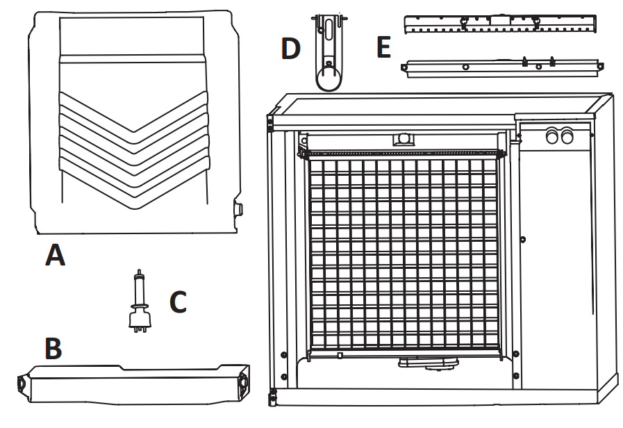
A. Remove the water curtain
- Gently flex the curtain in the center and remove it from the right side.
- Slide the left pin out.
B. Remove the water trough
- Depress tabs on right and left side of the water trough.
- Allow front of water trough to drop as you pull forward to disengage the rear pins.
C. Remove the water level probe
- Pull the water level probe straight down to disengage.
- Lower the water level probe until the wiring connector is visible.
- Disconnect the wire lead from the water level probe.
- Remove the water level probe from the ice machine.
D. Remove the ice thickness probe
- Compress the hinge pin on the top of the ice thickness probe.
- Pivot the ice thickness probe to disengage one pin then the other. The ice thickness probe can be cleaned at this point without complete removal. If complete removal is desired, disconnect the ice thickness control wiring from the control board.
E. Remove the water distribution tube
NOTE: Distribution tube thumbscrews are retained to prevent loss. Loosen thumbscrews but do not pull thumbscrews out of distribution tube.
- Loosen the two outer screws (do not remove screws completely they are retained to prevent loss) and pull forward on the distribution tube to release from slip joint.
Disassemble distribution tube by loosening the two (2) middle thumbscrews and dividing the distribution tube into two pieces. Please refer to the proper parts removal for your ice machine. Continue with step 6 when the parts have been removed.
Step 6 Mix a solution of cleaner/descaler and lukewarm water. Depending upon the amount of mineral buildup, a larger quantity of solution may be required. Use the ratio in the table below to mix enough solution to thoroughly clean all parts.
| Solution Type |
Water |
Mixed With |
| Cleaner |
1 gal. (4 L) |
16 oz (475 ml) cleaner |
Step 7 Use 1/2 of the descaler/water mixture to descale all components. The solution will foam when it contacts lime scale and mineral deposits; once the foaming stops use a soft-bristle nylon brush, sponge or cloth (NOT a wire brush) to carefully clean the parts. Soak parts for 5 minutes (15 - 20 minutes for heavily scaled parts). Rinse all components with clean water.
Ice Thickness Probe & Water Level Probe
Clean the probes using the following procedure.
NOTE: Do not soak electrical connectors in cleaner or sanitizer solution.
- Mix a solution of Manitowoc ice machine cleaner/ descaler and water (2 ounces of cleaner/descaler to 16 ounces of water) in a container.
- Clean all probe surfaces including all plastic parts (do not use abrasives). Verify all surfaces are clean. Thoroughly rinse probes with clean water.
- Reinstall probe, then sanitize the ice machine and bin/ dispenser interior surfaces.
Step 8 While components are soaking, use 1/2 of the descaler/water solution to descale all food zone surfaces of the ice machine and bin (or dispenser). Use a nylon brush or cloth to thoroughly descale the following ice machine areas:
- Side walls
- Base (area above water trough)
- Evaporator plastic parts - including top, bottom, and sides
- Bin or dispenser
Rinse all areas thoroughly with clean water.
SANITIZING PROCEDURE
Step 9 Mix a solution of sanitizer and lukewarm water.
| Solution Type |
Water |
Mixed With |
| Sanitizer |
3 gal. (12 L) |
2 oz (60 ml) sanitizer |
Step 10 Use 1/2 of the sanitizer/water solution to sanitize all removed components. Use a spray bottle to liberally apply the solution to all surfaces of the removed parts or soak the removed parts in the sanitizer/water solution. Do not rinse parts after sanitizing.
Step 11 Use 1/2 of the sanitizer/water solution to sanitize all food zone surfaces of the ice machine and bin (or dispenser). Use a spray bottle to liberally apply the solution. When sanitizing, pay particular attention to the following areas:
- Side walls
- Base (area above water trough)
- Evaporator plastic parts - including top, bottom and sides
- Bin or dispenser
Do not rinse the sanitized areas.
Step 12 Replace all removed components. Step 13 Wait 20 minutes.
Step 14 Reapply power to the ice machine and press the Clean button.
Step 15 Press the Clean button and select “Make ice when complete”. Water will flow through the water dump valve and down the drain. Wait approximately 1 minute until the water trough refills and the display indicates Add Chemical. Add the proper amount of ice machine sanitizer to the water trough by pouring between the water curtain and evaporator, then confirm the chemical was added.
| Model |
Amount of Sanitizer |
| IF0300/IT0300/IT0420/IT0450 IT0620/IT0450/IF0500/IT0500 IF0600/IT0750/IF0900/IT0900 IT1200 |
3 ounces (90 ml) |
| IT1500/IT1900 |
6 ounces (180 ml) |
Step 16 The ice machine will automatically start ice making after the sanitize cycle is complete.
Water Inlet Valve
- The water inlet valve normally does not require removal for cleaning. Refer to “Water System Checklist” page 109, if you are troubleshooting water related problems.
- When the ice machine is off, the water inlet valve must completely stop water flow into the machine. Watch for water flow.
- When the ice machine is on, the water inlet valve must allow the proper water flow through it. Press the On/ Off button to energize the ice machine. Watch for water flow into the ice machine. If the water flow is slow or only trickles into the ice machine, refer to water system checklist.
- NOTE: The valve can also be energized by navigating to the service diagnostic menu, selecting control board, then selecting “enable all relays”.
Water Dump Valve
- The water dump valve normally does not require removal for cleaning. To determine if removal is necessary:
- Locate the water dump valve.
- While the ice machine is in the freeze mode, check the drain to determine if the dump valve is leaking. If there is no or little water in the water trough (during the freeze cycle) the dump valve is leaking.
- If the dump valve is leaking and debris is not visible and easily removed, the dump valve must be replaced.
- If the dump valve is not leaking, do not remove it. Instead, follow the “Ice Machine Cleaning Procedure”.
Remedial Cleaning Procedure
This procedure will descale the components in the water flow path, and is used to descale the ice machine between the bi-yearly cleaning/descaling and sanitizing procedure.
Ice machine cleaner/descaler is used to remove lime scale and mineral deposits. Ice machine sanitizer disinfects and removes algae and slime.
NOTE: Although not required and dependent on your installation, removing the ice machine top cover may allow easier access.
- Ice must not be on the evaporator during the descaling/sanitize cycle. Follow one of the methods below:
- Press the power switch at the end of a harvest cycle after ice falls from the evaporator(s).
- Press the power switch and allow the ice to melt.
- Open the front door to access the evaporator.
- Press the Clean button and select “Make ice when complete”. Water will flow through the water dump valve and down the drain. Wait approximately 1 minute until the water trough refills and the display indicates Add Chemical. Add the proper amount of ice machine cleaner/descaler to the water trough by pouring between the water curtain and evaporator, then confirm the chemical was added.
| Model |
Amount of Cleaner/Descaler |
| IF0300/IT0300/IT0420/IT0620 |
3 ounces (90 ml) |
| IT0450/IF0500/IT0500/IF0600 IT0750/IF0900/IT0900/IT1200 |
5 ounces (150 ml) |
| IT1500/IT1900 |
9 ounces (265 ml) |
- Close and secure the front door. The ice machine will automatically start ice making after the cycle is complete (approximately 24 minutes).
NOTE: Once the cycle has started it must complete before the ice machine can make ice again. Returning it to ice making mode will not cancel a clean cycle.
Removal from Service/Winterization
General
- Special precautions must be taken if the ice machine is to be removed from service for an extended period of time or exposed to ambient temperatures of 32°F (0°C) or below.
- Notice: If water is allowed to remain in the ice machine in freezing temperatures, severe damage to some components could result. Damage of this nature is not covered by the warranty.
- Follow the applicable procedure below.
AIR-COOLED ICE MACHINES
- Turn off the ice machine by pressing the On/Off Button.
- Turn off the water supply.
- Remove the water from the water trough.
- Disconnect and drain the incoming ice-making water line at the rear of the ice machine.
- Energize the ice machine and wait one minute for the water inlet valve to open - or - Energize all relays in the touchscreen service menu.
- Blow compressed air in both the incoming water and the drain openings in the rear of the ice machine until no more water comes out of the water inlet lines or the drain.
- Disconnect the electric power at the circuit breaker or the electric service switch.
- Make sure water is not trapped in any of the water lines, drain lines, distribution tubes, etc.
WATER-COOLED ICE MACHINES
- Perform steps 1-6 under “Air-Cooled Ice Machines”.
- Disconnect the incoming water and drain line from the water-cooled condenser.
- Start the ice making cycle by pressing the On/Off button and wait for the freeze cycle. The increasing refrigerant pressure will open the water regulating valve.
- Blow compressed air through the condenser until no water remains. Turn off ice machine by
- ressing the On/Off button and then disconnecting power to the ice machine.
- Perform a lock out tag out procedure.
Operation

Touch Screen Features
- The Indigo® control panel offers a series of pressuresensitive buttons and an interactive touchscreen.
- Buttons
- On/Off Button: Provides On/Off functions for the ice machine.
- Lock/Unlock Button: Allows or prevents touchscreen navigation.
- Cleaning Button: Initiates a cleaning cycle. Refer to “Detailed Cleaning and Sanitizing” on page 37 for details.
Touchscreen

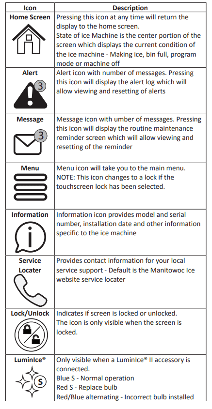
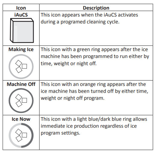
HOME SCREEN ICON DESCRIPTIONS
Setup Wizard
- Screens will automatically advance after a selection is made or press the arrows to advance/go back one screen. All settings can be accessed and changed without the wizard by using menu screen navigation.
| Setup |
Description |
| Press ON/OFF Button |
On/Off button is used to start/stop ice making. |
| Select Language |
Default is English. Scroll to select a different language. |
| Start Wizard |
Setup wizard will guide ice machine programming |
| Date and Time Configuration |
Select Month/Day/Year or Day/Month/Year. Select 12 hour or 24 hour time format. |
| Set Local Time |
Use arrows to set local time. |
| Verify Date |
Use arrows to set date for your location |
| Accessory Detection |
Detects if Ice Level Sensor, LuminIce® II or iAuCS are connected. Checkmark = yes - X = no |
| Optional USB Settings Download |
Only used when setup features have been transferred to a USB drive. Skip screen by selecting right arrow. |
| Configure Units |
Select standard or metric. |
| Set Brightness |
Configure screen brightness during normal operation |
| Optional Ice Program |
Program ice machine run times or press right arrow to skip this setup |
| Optional Cleaning Reminder |
Set clean and sanitize reminder or press right arrow to skip. |
| Optional Clean Air Filter Air-cooled models only |
Set to ON for self-contained air cooled models. |
| Optional Water Filter Reminder |
Select Yes or No. |
| Water Usage Option |
Factory default - or - Use less water for reverse osmosis systems (Refer to “Reverse Osmosis or Deionized Water Usage” on page 148) - or - Use more water to improve clarity for unfiltered water |
| Congratulations |
Setup wizard is complete |
| Turn On Ice Machine |
Turn on ice machine by pressing the On/Off button. |
Menu Navigation Overview
SETTINGS MENU SCREEN NAVIGATION
- Select SETTINGS Icon from the Home Screen to access Main Menu screen. The main menu screen contains four main headings, which allow access to subheadings under each main heading
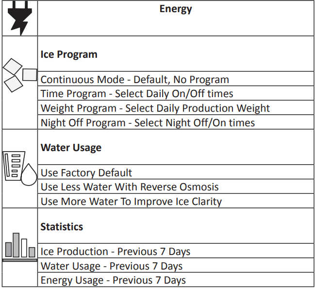
- NOTE: The performance statistics are calculated based on the performance of the ice machine at 90°F (32°C) ambient temperature and 70°F (21°C) water temperature. The actual statistics will vary dependent on your environmental conditions.
Troubleshooting
Troubleshooting
- Check the touchscreen for alerts - An alert icon with the number of messages will be displayed if alerts are present. Pressing the alert icon will display the alert log which will allow viewing and resetting of alerts. Refer to the alert log and event log on the following pages for a description of the event.
- NOTE: There are two sequences that allow the ice machine to continue ice making during alert events:
- Thaw Cycle :When the damper/curtain does not open during the 7 minute harvest cycle (E02 fault) a thaw cycle starts. See “Thaw Cycle” on page 86
- Safe Operation Mode: Allows the ice machine to operate up to 72 hours if the ice thickness probe (E19 fault) and/or water level probe sensors fail (E20 fault). See “Safe Operation Mode” on page 87
EVENT LOG
Refer to “Event Log Detail” For Code descriptions.
| Displayed Text |
Code |
Description |
| Long Freeze |
E01 |
Long Freeze Cycle |
| Long Harvest |
E02 |
Long Harvest Cycle |
| Power Loss |
E03 |
Input Power Loss |
| Hi cnd Temp or Wtr Cnd Fault |
E04 |
High Condenser Temperature |
| HPC Fault |
E05 |
High Pressure Control Opened |
| |
E06 |
Spare |
| Starving TXV |
E07 |
Starving TXV Single Evaporator or Low On Charge |
| TXV Fault |
E08 |
TXV Fault Single or Dual Circuit Evaporators |
| Flood Evap1 |
E09 |
Flooding Evaporator Fault Single Evaporator, Single Circuit |
| Flood Evap2 |
E10 |
Flooding Evaporator Fault Dual TXV, Dual Circuit |
| Refrig Fault |
E11 |
Refrigeration Fault |
| Curtain Fault |
E12 |
Curtain Switch Fault - Open more than 24 hours |
| |
E13 |
Spare |
| |
E14 |
Spare |
| Low liq temp |
E15 |
Fan Cycle Control Fault - Low Liquid Line Temperature |
| Rmt Cnd Fault |
E16 |
Remote Condensing Unit Fault (CVD Only) |
| |
E17 |
Spare |
| |
E18 |
Spare |
| ITP Fault |
E19 |
Ice Thickness Probe Fault |
| WTR Fault |
E20 |
Water System Fault |
| T1 Fault |
E21 |
T1 Temperature Sensor Issue |
| T2 Fault |
E22 |
T2 Temperature Sensor Issue |
| T3 Fault |
E23 |
T3 Temperature Sensor Issue |
| T4 Fault |
E24 |
T4 Temperature Sensor Issue |
| Bin Probe Fault |
E25 |
Bin Level Probe Low Sensor Fault |
| AUCS |
E26 |
T6 or T7 Temperature Sensor Issue |
| USB COMM |
E27 |
T6 or T7 Temperature Sensor Issue |
| USB DNLD |
E28 |
iAuCS |
| |
E29 |
USB Communication Fault |
| |
E30 |
USB Download Fault |
| Safe Mode |
E31 |
Safe Mode |
| RS485 COMM |
E32 |
RS485 Communication Fault |
| Keyboard |
E33 |
Touchscreen Fault |
| Display |
E34 |
Display Fault |
| Checksum |
E36 |
Check Sum Error |
| WatchDog |
E37 |
Watch Dog Event |
| UI Comm |
E38 |
UI Comm Event |
EVENT LOG DETAIL
- E01 Long Freeze: 3 consecutive 35 minute freeze cycles = Ice machine is off.
- E02 Long Harvest: 3 consecutive 7minute harvest cycles = Ice machine is off.
- E03 Power Loss: When power is interrupted to the ice machine the control board will log the event in the ELOG and stamp the loss of power on power-up.
- E04 High Condenser Temperature: Liquid Line Temperature too High for Self-contained Air Cooled Ice machine = Air Cooled Condenser Fault Or Liquid Line Temperature too High for Self-contained Water Cooled ice machine = Water Cooled Condenser Fault
- E05 High Pressure Control Opened: The high pressure cutout switch (HPCO) opened.
- E06: Spare
- E07 Starving TXV Single Evaporator or Low On Charge: The difference of the average evaporator inlet (T3) and outlet (T4) is greater than 12°F in the last 1 minute of the freeze cycle.
- E08 TXV Fault Single or Dual Circuit Evaporators: The difference of the average evaporator inlet (T3) and outlet (T4) is greater than 12°F in the last 1 minute of the freeze cycle.
- E09 Flooding Evaporator Fault Single Evaporator, Single Circuit: Average compressor discharge line temperature during the first 6 minutes of the freeze cycle (T2) compared to the average of the Prechill (T1) +50°F is less than 1.05°F.
- E10 Flooding Evaporator Fault Dual TXV, Dual Circuit: Average compressor discharge line temperature during the first 6 minutes of the freeze cycle (T2) compared to the average of the Prechill (T1) +50°F is less than 1.05°F.
- E11 Refrigeration Fault: The compressor discharge temperature did not increase by at least 10° F, and the evaporator temperature did not decreased by at least 10° F - Measured from Refrigeration Start up or Prechill until 2 minutes into the Freeze cycle.
- E12 Curtain Switch Fault: Open more than 24 hours The ice machine is set to ice making and remains in bin full condition for more than 24 hours. The curtain switch is open or curtain is off.
- E13: Spare
- E14: Spare
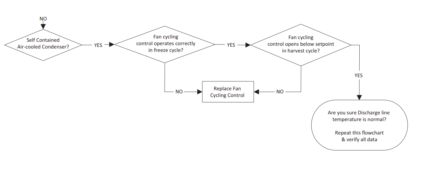
- E15 Fan Cycle Control Fault - Low Liquid Line Temperature: The liquid line temperature dropped below 60° F for more than one continuous minute during the freeze cycle.
- E16 Remote Condensing Unit Fault (CVD Only): The liquid line temperature dropped below 40° F, or exceeded 140° F for more than 1 continuous minute during the freeze cycle.
- E17: Spare
- E18: Spare
- E19 Ice Thickness Probe Fault: The monitored Frequencies is out of the appropriate range (probe unplugged or problem with microphone).
- E20 Water System Fault: Any of the following:
- Sensing high water probe and not low water probe.
- Evaporator outlet temperature is less than -10°F 6.5 to 7.5 minutes in freeze cycle.
- Low water probe is satisfied at the end of harvest.
- Low or high water probe is satisfied at end of freeze cycle.
- E21 T1 Temperature Sensor Issue During: Pre-chill the thermistor had an average value reading outside the valid range.
- E22 T2 Temperature Sensor Issue: During Pre-chill the thermistor had an average value reading outside the valid range.
- E23 T3 Temperature Sensor Issue: During Pre-chill the thermistor had an average value reading outside the valid range.
- E24 T4 Temperature Sensor Issue: During Pre-chill the thermistor had an average value reading outside the valid range.
- E25 Bin Level Probe Low Sensor Fault: The thermistor had an average value reading outside of the valid range for 10 continuous minutes.
- E26 T6 or T7 Temperature Issue: The thermistor had an average value reading outside of the valid range.
- E27 - T6 or T7 Temperature Issue: The thermistor had an average value reading outside of the valid range.
- E28 iAuCS: When the iAuCS clean option is selected from the menu, the control checks for the presence of the iAuCS board. When the iAuCS is not connected it will signal an Event which will clear as soon as the hardware is detected.
- E29: USB: Communication Fault USB Communication error; No USB drive in port or defective USB drive.
- E30: USB: Download Fault USB Download error related to USB drive or a defective USB drive.
- E31: Safe Mode: Safe mode allows the ice machine to operate for a period of time in the event of a Water level or ice thickness probe failure. The controller allows the machine to operate based on model data and historical cycle information.
- E32: RS485 Communication Fault: The device plugged into the RS485 port is not communicating between the control board and gateway.
- E33: Touchscreen Fault: The Touchscreen is not plugged into the control board or is faulty.
- E34: Display Fault: The touchscreen is not plugged into the control board or is faulty
- E36 Check Sum Error: Event Log Only: Activates on power loss.
- E37 Watch Dog Event: Event Log Only: Micro Process time out, possible electrical noise.
- E38 UI Comm Event: Event Log Only User interface communication error: loose communication cable, power interruption.
THAW CYCLE
When the damper/curtain does not open during the 7 minute harvest cycle the following Thaw Cycle occurs:
- 7 minutes - The compressor, harvest solenoid valve and dump valve de-energize. The water pump remains energized and the water inlet valve energizes until water touches the high water level probe.
- Water is circulated, dumped and refilled to the high water level probe 18 times (approximately 1 hour). Model 1200 or smaller: Circulate 165 seconds, dump 45 seconds Model 1400 and larger: Circulate 240 seconds, dump 120 seconds
- At the end of the thaw cycle (approximately 1 - 1.75 hour) the ice machine will start another freeze cycle.
Curtain Operation In Thaw Cycle Harvest
- Open & close damper = Continue Thaw Cycle
- Open damper 30 seconds = Full Bin Shutoff
Use the keypad and turn the ice machine off and then on to terminate the cycle. Disconnecting and reconnecting power to end the cycle will result in the ice machine restarting in a harvest cycle.
SAFE OPERATION MODE
Allows the ice machine to operate up to 72 hours if the ice thickness probe (E19 fault) and/or water level probe sensors fail (E20 fault).
- When the control board starts the safe mode an alert is indicated to notify the end-user they have a production problem.
- The control board automatically initiates and monitors the safe mode. The control will automatically exit the safe mode if a normal signal is received from the input.
- After 72 hours the control board will enter a standby mode and turn off.
- The control board needs a five cycle history to operate safe mode. If five cycles have never been successfully completed the ice machine will shut-off.
E01 LONG FREEZE CYCLE
- If the freeze time reaches 35 minutes, the control board automatically initiates a harvest cycle. If 3 consecutive 35-minute freeze cycles occur, the ice machine stops.
E02 LONG HARVEST CYCLE
- If the harvest time reaches 7 minutes, the control board will start a Thaw Cycle and automatically return the ice machine to the freeze cycle. After 3 consecutive long harvest cycles the ice machine stops.
ANALYZING WHY A SERVICE FAULT (E01 & E02) STOPPED THE ICE MACHINE
- Service Faults are designed to stop the ice machine prior to major component failures, most often a minor problem or something external to the ice machine. This may be difficult to diagnose, as many external problems occur intermittently.
- Example: An ice machine stops intermittently on Service Fault (long freeze times). The problem could be a low ambient temperature at night, a water pressure drop, the water is turned off one night a week, etc.
- Refrigeration and electrical component failures will cause a Service Fault trip. Eliminate all electrical components and external causes first. If it appears that the refrigeration system is causing the problem, use Manitowoc’s Freeze Cycle Refrigeration System Operational Analysis Table, along with detailed charts, checklists, and other references to determine the cause.
- The following checklists are designed to assist the service technician in analysis. However, because there are many possible external problems, do not limit your diagnosis to only the items listed.
E01 LONG FREEZE
Freeze time exceeds 35 minutes for 3 consecutive freeze cycles.
Possible cause checklist
Improper Installation
- Refer to “Installation/Visual Inspection Checklist” on page 108
Water System
- Dirty/defective water level probe
- Low water pressure (20 psig min.)
- High water pressure (80 psig max.)
- High water temperature (90°F/32.2°C max.)
- Clogged water distribution tube
- Dirty/defective water fill valve
- Dirty/defective water dump valve
- Defective water pump
- Loss of water from sump area
Electrical System
- Low incoming voltage
- Ice thickness probe out of adjustment
- Harvest cycle not initiated electrically
- Contactor not energizing
- Compressor electrically non-operational
- Defective fan cycling control
- Defective fan motor
Miscellaneous
- Non-Manitowoc components
- Improper refrigerant charge
- Defective head pressure control
- Defective harvest valve
- Defective compressor
- TXV starving or flooding (check bulb mounting)
- Non-condensible in refrigeration system
- Plugged or restricted high side refrigerant lines or component
- Restricted air flow/dirty condenser fins
- High inlet air temperature
- Condenser discharge air recirculation
E02 LONG HARVEST
Harvest time exceeds 7 minutes for 3 consecutive harvest cycles.
Possible Cause Checklist
Improper Installation
- Refer to “Installation/Visual Inspection Checklist” on page 108
Water System
- Water area (evaporator) dirty
- Dirty/defective water dump valve
- Vent tube not installed on water outlet drain
- Water freezing behind evaporator
- Plastic extrusions and gaskets not securely mounted to the evaporator
- Clogged water distribution tube
Electrical System
- Ice thickness probe out of adjustment
- Bin switch closed/defective
- Premature harvest - The control board initiates a harvest cycle when the high water level probe circuit is complete and the low water level probe is open.
Refrigeration System
- Non-Manitowoc components
- Improper refrigerant charge
- Defective head pressure control valve
- Defective harvest valve
- TXV flooding (check bulb mounting)
- Defective fan cycling control
- Water cooled only - Water regulating valve is incorrectly adjusted or will not close during harvest cycle.
Troubleshooting By Symptom
The troubleshooting procedures follow diagnostic charts. There are four symptoms, the symptom that you are experiencing will determine which diagnostic chart to use. The chart asks yes and no questions to determine the problem. The diagnostic chart will direct you to a procedure to correct the problem. Remote condenser, and self contained models use separate charts.
SYMPTOM #1: Ice Machine Stops Running - Ice machine is in Ice Making cycle or Has a History of Shutting Down
- Refer to Ice Machine Stops Running diagnostic chart
SYMPTOM #2:
- Ice Machine has a Long Freeze Cycle - Ice Formation is Thick or Thin Ice Fill on Inlet or Outlet of Evaporator or Low Production
- Service Fault (possible)
- Refer to Freeze Cycle Refrigeration System Operational Analysis Table
SYMPTOM #3
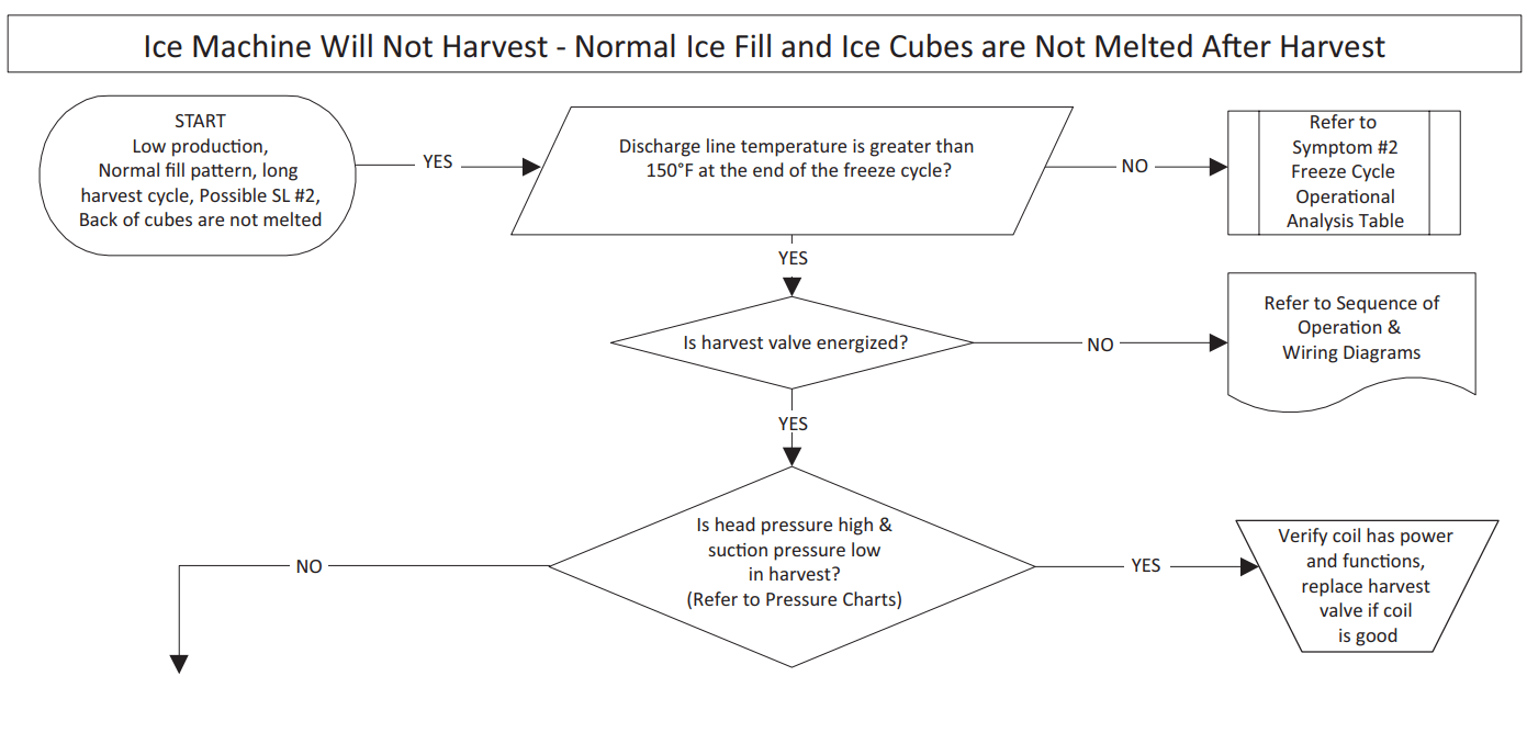
- Ice Machine Will Not Harvest - Freeze Cycle is Normal and Ice Cubes are Not Melted After Harvest
- Long Harvest (possible)
- Refer to Refrigeration Harvest Flow Chart
SYMPTOM #4
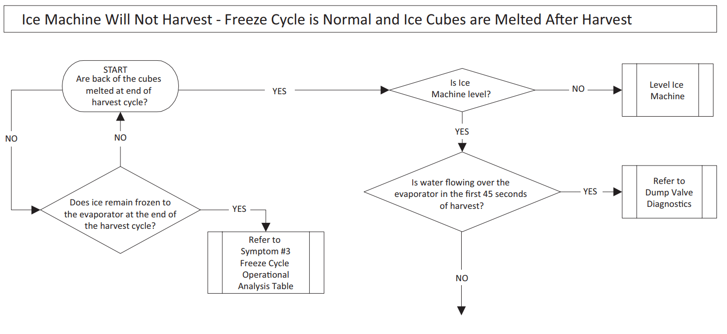
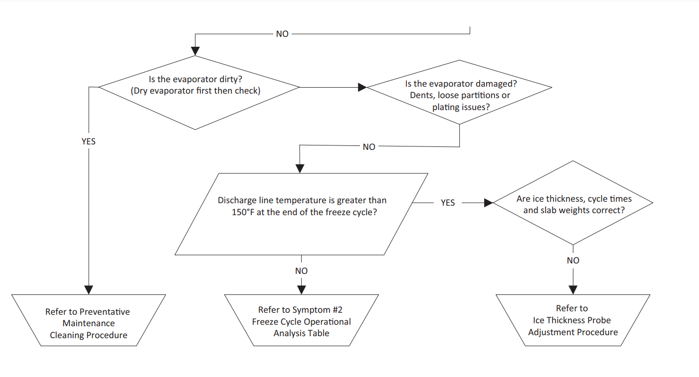
- Ice Machine Will Not Harvest - Freeze Cycle is Normal and Ice Cubes are Melted After Harvest
- Refer to Ice Meltout Flow Chart
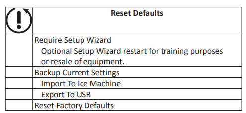
RESET TO FACTORY DEFAULTS
- Before starting troubleshooting procedures, reset the control board to factory defaults to prevent mis-diagnosis. Before resetting to factory defaults do one of the following:
- Copy settings to a USB device and flash settings into the control board when diagnostics are complete.
- Write down any customer settings so they can be re-entered when diagnostics are complete.
- To reset the ice machine to factory defaults select Menu then Reset Defaults.
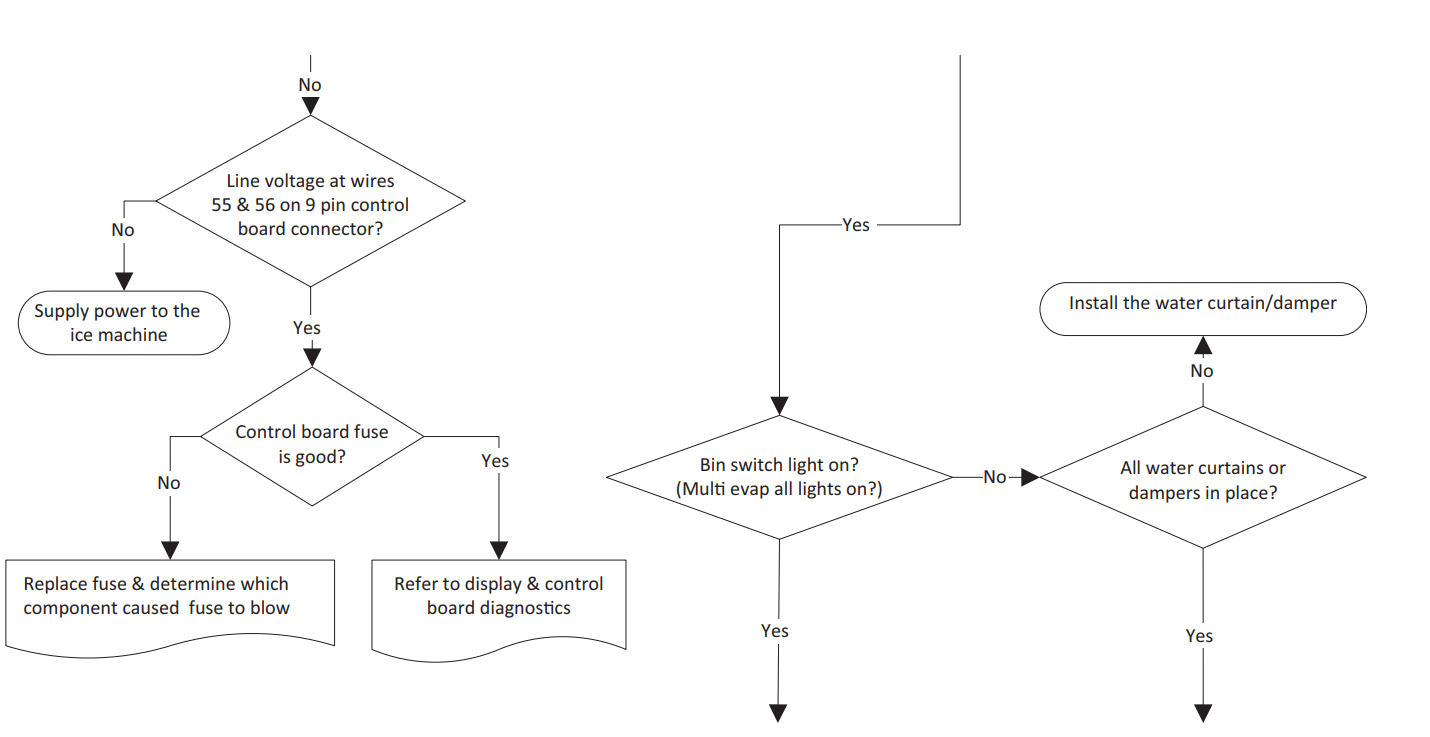
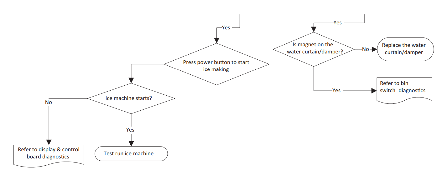
SYMPTOM #1 - ICE MACHINE WILL NOT RUN

#2 - LOW PRODUCTION, LONG FREEZE CYCLE
Ice Machine has a Long Freeze Cycle: Ice Formation is Thick or Thin on Inlet or Outlet of Evaporator or Low Production
How to Use the Freeze Cycle Refrigeration System Operational Analysis Table
GENERAL
- These tables must be used with charts, checklists and other references to eliminate refrigeration components not listed on the tables and external items and problems which can cause good refrigeration components to appear defective.
- The tables list five different defects that may affect the ice machine’s operation.
- NOTE: A low-on-charge ice machine and a starving expansion valve have very similar characteristics and are listed under the same column.
- NOTE: Before starting, see “Before Beginning Service” for a few questions to ask when talking to the ice machine owner.
PROCEDURE
- Step 1 Complete the “Operation Analysis” column.
- Read down the left “Operational Analysis” column. Perform all procedures and check all information listed. Each item in this column has supporting reference material to help analyze each step.
- While analyzing each item separately, you may find an “external problem” causing a good refrigerant component to appear bad. Correct problems as they are found. If the operational problem is found, it is not necessary to complete the remaining procedures.
- Step 2 Enter Checkmarks (√).
- Each time the actual findings of an item in the “Operational Analysis” column matches the published findings on the table, enter a Checkmark.
- Example: Freeze cycle suction pressure is determined to be low. Enter a Checkmark in the “low” column.
- Step 3 Add the Checkmarks listed under each of the four columns. Note the column number with the highest total and proceed to “Final Analysis.”
- NOTE: If two columns have matching high numbers, a procedure was not performed properly, supporting material was not analyzed correctly or the problem component is not covered by the analysis table.
Before Beginning Service
Ice machines may experience operational problems only during certain times of the day or night. A machine may function properly while it is being serviced, but malfunctions later. Information provided by the user can help the technician start in the right direction, and may be a determining factor in the final diagnosis.
Ask these questions before beginning service:
- When does the ice machine malfunction? (night, day, all the time, only during the Freeze cycle, etc.)
- When do you notice low ice production? (one day a week, every day, on weekends, etc.)
- Can you describe exactly what the ice machine seems to be doing?
- Has anyone been working on the ice machine?
- During “store shutdown,” is the circuit breaker, water supply or air temperature altered?
- Is there any reason why incoming water pressure might rise or drop substantially?
SYMPTOM #2 - FREEZE CYCLE REFRIGERATION SYSTEM OPERATIONAL ANALYSIS TABLES
Ice Production Check
The amount of ice a machine produces directly relates to the operating water and air temperatures. This means a condensing unit with a 70°F (21°C) outdoor ambient temperature and 50°F (10°C) water produces more ice than the same model condensing unit with a 90°F (32°C) outdoor ambient temperature and 70°F (21°C) water.
- Determine the ice machine operating conditions: Air temp entering condenser:____° Water temp entering sump trough:____°
- Refer to the appropriate 24-Hour Ice Production Chart (starting on page 201). Use the operating conditions determined in step 1 to find published 24-Hour Ice Production:_____
- Times are in minutes. Example: 1 min. 15 sec. converts to 1.25 min. (15 seconds ÷ 60 seconds = .25 minutes)
- Weights are in pounds. Example: 2 lb. 6 oz. converts to 2.375 lb. (6 oz. ÷ 16 oz. = .375 lb.)
- Perform an ice production check using the formula below.
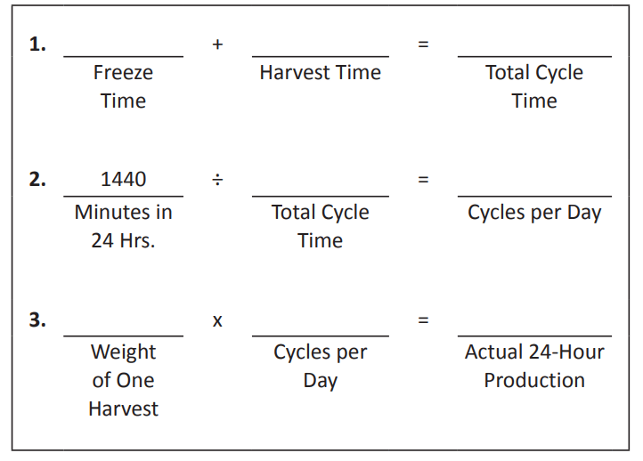
Weighing the ice is the only 100% accurate check.
However, if the ice pattern is normal and the 1/8" thickness is maintained, the ice slab weights listed with the 24-Hour Ice Production Charts may be used.
4. Compare the results of step 3 with step 2. Ice production checks that are within 10% of the chart are considered normal. If they match closely, determine if:
- Another ice machine is required.
- More storage capacity is required.
- Relocating the existing equipment to lower the load conditions is required.
Contact the local Manitowoc Distributor for information on available options and accessories.
Installation/Visual Inspection Checklist
- Inadequate Clearances
- Check all clearances on sides, back and top. Reference “Clearance Requirements” on page 26
- Ice machine is not level
- Condenser is dirty
- Water filtration is plugged (if used)
- Install a new water filter
- Water drains are not run separately and/or are not vented
- Run and vent drains according to the Installation Manual
- Floor drain must have an air gap
- Install condensation drain in the ice machine base
- Line set is improperly installed
- Reinstall according to the Installation Manual Reference “Location of Ice Machine” on page 25
Water System Checklist
- A water-related problem often causes the same symptoms as a refrigeration system component malfunction.
- Water system problems must be identified and eliminated prior to replacing refrigeration components.
- Water area (evaporator) is dirty: Clean as needed
- Water inlet pressure not between 20 and 80 psig (1-5 Bar, 138-552 kPa):
- Install water regulator or increase water pressure
- Incoming water temperature is not between 35°F (2°C) and 90°F (32°C)
- If too hot, check the hot water line check valves in other store equipment
- Water filtration is plugged (if used): Install a new water filter
- Water dump valve leaking during the Freeze cycle: Clean/replace dump valve as needed
- Vent tube is not installed on water outlet drain: See Installation Instructions
- Hoses, fittings, etc., are leaking water: Repair/replace as needed
- Water fill valve is stuck open or closed: Clean/replace as needed
- Water is leaking out of the sump trough area: Stop the water loss
- Uneven water flow across the evaporator: Clean the ice machine
- Plastic extrusions and gaskets are not secured to the evaporator: Remount/replace as needed
Ice Formation Pattern
- Evaporator ice formation pattern analysis is helpful in ice machine diagnostics.
- Analyzing the ice formation pattern alone cannot diagnose an ice machine malfunction. However, when this analysis is used along with Manitowoc’s Freeze Cycle Refrigeration System Operational Analysis Tables, it can help diagnose an ice machine malfunction.
- Any number of problems can cause improper ice formation.
- Important: Keep the water curtain/ice dampers in place while checking the ice formation pattern to ensure no water is lost.
1. Normal Ice Formation
- Ice forms across the entire evaporator surface. At the beginning of the Freeze cycle, it may appear that more ice is forming on the inlet of the evaporator than on the outlet. At the end of the Freeze cycle, ice formation at the outlet will be close to, or just a bit thinner than, ice formation at the inlet. The dimples in the cubes at the outlet of the evaporator may be more pronounced than those on the inlet. This is normal.
- It is normal for ice thickness to vary up to 1/16" across the surface of the evaporator. The ice bridge thickness at the ice thickness control probe should be at least 1/8".
- The ice thickness probe must be set to maintain the ice bridge thickness at approximately 1/8" If ice forms uniformly across the evaporator surface, but does not reach 1/8" in the proper amount of time, this is still considered a normal ice fill pattern.
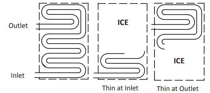
2. Extremely Thin at Evaporator Outlet
- There is no ice, or a considerable lack of ice formation, at the outlet of the evaporator.
- Examples: No ice at all on the outlet half of the evaporator, but ice forms on the inlet half of the evaporator. Or, the ice at the outlet of the evaporator reaches 1/8" to initiate a harvest, but the inlet of the evaporator already has 1/2" to 1" of ice formation.
3. Extremely Thin at Evaporator Inlet
- There is no ice, or a considerable lack of ice formation at the inlet of the evaporator. Examples: The ice at the outlet of the evaporator reaches 1/8" to initiate a harvest, but there is no ice formation at all on the inlet of the evaporator.
4. No Ice Formation
The ice machine operates for an extended period, but there is no ice formation at all on the evaporator.
- Evaporator Tubing Routing: Routing of the tubing on the back of the evaporator determines the ice fill pattern failure mode.
- One Evaporator, One TXV models: The evaporator outlet tubing does not exit directly at the top of the evaporator, but exits several inches below the top of the evaporator. Extremely Thin at the Evaporator Outlet will first be visible several inches below the top of the evaporator. Extremely Thin at Evaporator Inlet will first be visible at the bottom of the evaporator.
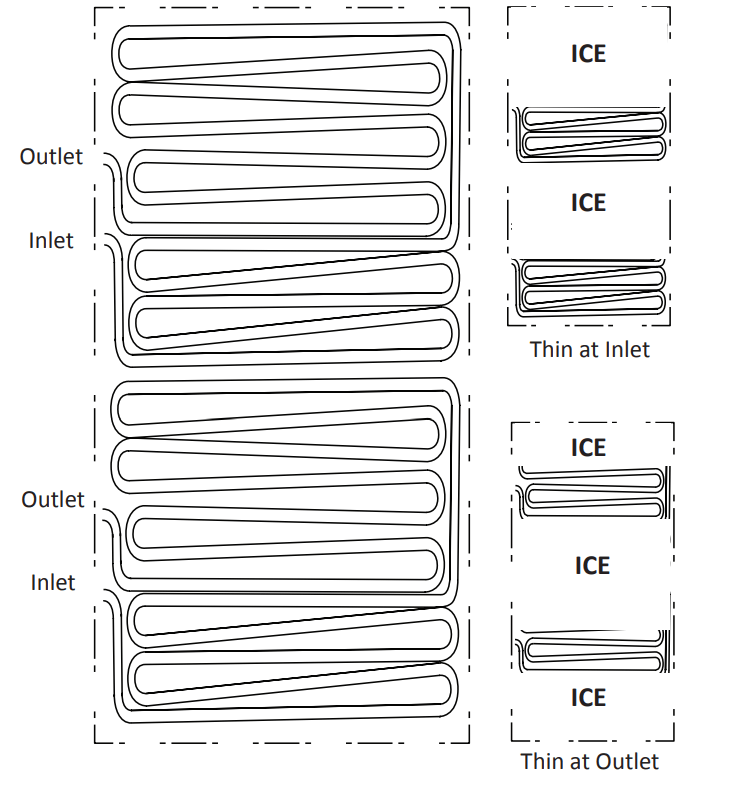
- One Evaporator, Two TXV 30" Models: Tubing routing for one evaporator with two TXV’s is different. The evaporator has two inlets and outlets. Fill pattern varies depending on which circuit is affected,
- Extremely Thin at the Evaporator Outlet will first be visible either 1/4 or 3/4 of the way down the evaporator.
- Extremely Thin at the Evaporator: Inlet will show at the bottom of the evaporator or 1/2 of the way down depending on the circuit affected.
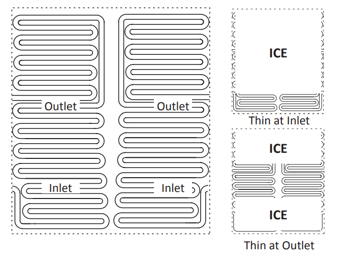
- One Evaporator, Two TXV 48" Model:s Tubing routing for one evaporator with two TXV’s is different. The evaporator has two inlets and outlets. Fill pattern varies depending on which circuit is affected.
- Extremely Thin at the Evaporator Outlet will first be visible 1/3 of the way down the evaporator. Only one side of the evaporator may be affected depending on failure. A TXV failure will usually show on only one side, while low on refrigerant can affect one or both sides depending on the amount of refrigerant loss and ambient temperature.
- Extremely Thin at the Evaporator Inlet will show at the bottom of the evaporator. Depending on the failure either the entire bottom of the evaporator or one side of the bottom of the evaporator may be affected.
Analyzing Discharge Pressure in the Freeze Cycle
- Determine the ice machine operating conditions:
- Air temp. entering condenser ______ °
- Water temp. entering sump trough ______ °
- Refer to Operating Pressure table (starting on page 201) for ice machine being checked.
- Use the operating conditions determined in step 1 to find the published normal discharge pressures:
- Freeze Cycle ______
- Harvest Cycle ______
- Perform an actual discharge pressure check. Freeze Cycle psig (kPa)
- 1 Minute into the Freeze Cycle __________
- Middle of Freeze Cycle __________
- End of Freeze Cycle __________
- Compare the actual discharge pressure (step 3) with the published discharge pressure (step 2). The discharge pressure is normal when the actual pressure falls within the published pressure range for the ice machine’s operating conditions. It is normal for the discharge pressure to be higher at the beginning of the Freeze cycle (when load is greatest), then drop throughout the Freeze cycle.
Freeze Cycle Discharge Pressure High Checklist
Improper Installation
- Refer to “Installation/Visual Inspection Checklist” on page 108
Air Condenser
- Dirty condenser filter
- Dirty condenser fins
- High inlet air temperature
- Condenser discharge air recirculation
- Defective fan cycling control
- Defective fan motor
- Defective head pressure control valve (Remote)
Water Condenser
- Low water pressure (20 psig [138 kPa] min.)
- High inlet water temperature (90°F/32°C max.)
- Dirty condenser
- Dirty/Defective water regulating valve
- Water regulating valve out of adjustment
Other
- Overcharged
- Non-condensible (air) in system
- Wrong type of refrigerant
- Non-Manitowoc components in system
- High side refrigerant lines/component restricted
Freeze Cycle Discharge Pressure Low Checklist
Improper Installation
- Refer to “Installation/Visual Inspection Checklist” on page 108
Air Cooled Condensers
- Defective head pressure control valve, won’t bypass refer to “Head Pressure Control Valve” on page 171
- Defective fan cycle control, stuck closed refer to “Fan Cycle Control” on page 164
Water Cooled Condensers
- Water Regulating Valve out of adjustment
- Water Regulating Valve Defective
Other
- Undercharged
- Wrong type of refrigerant
- Non-Manitowoc components in system
- Liquid line/component restricted
Analyzing Suction Pressure
- The suction pressure gradually drops throughout the freeze cycle. The actual suction pressure (and drop rate) changes as the air and water temperature entering the ice machine changes. These variables also determine the freeze cycle times.
- To analyze and identify the proper suction pressure drop throughout the freeze cycle, compare the published suction pressure to the published freeze cycle time.
- NOTE: Analyze discharge pressure before analyzing suction pressure. High or low discharge pressure may be causing high or low suction pressure.
- Determine the ice machine operating conditions:
- Air temp. entering condenser ______ °
- Water temp. entering sump trough ______ °
- Refer to Operating Pressure table (starting on page 201 for ice machine being checked:
- Use the operating conditions determined in step 1 to find the published normal discharge pressures.
- Freeze Cycle ______
- Harvest Cycle ______
- Perform an actual suction pressure check. Freeze Cycle psig (kPa)
- 1 Minute into the Freeze Cycle __________
- Middle of Freeze Cycle __________
- End of Freeze Cycle __________
- Compare the actual suction pressure (step 3) with the published suction pressure (step 2).
- NOTE: The suction pressure is normal when the actual pressure falls within the published pressure range for the ice machine’s operating conditions. It is normal for the suction pressure to be higher at the beginning of the Freeze cycle (when load is greatest), then drop throughout the Freeze cycle.
Suction Pressure High Checklist
Improper Installation
- Refer to “Installation/Visual Inspection Checklist” on page 108
Discharge Pressure
- Discharge pressure is too high and is affecting suction pressure – refer to “Freeze Cycle Discharge Pressure High Checklist” on page 115 Improper Refrigerant Charge
- Overcharged (also see “Freeze Cycle Discharge Pressure High Checklist” on page 115)
- Wrong type of refrigerant
- Non condensible in system
Components
- Harvest valve leaking
- Harvest pressure solenoid valve leaking
- TXV flooding
- Defective compressor
Other
- Non-Manitowoc components in system
Suction Pressure Low Checklist
Improper Installation
- Refer to “Installation/Visual Inspection Checklist” on page 108
Discharge Pressure
- Discharge pressure is too low and is affecting low side – refer to “Freeze Cycle Discharge Pressure Low Checklist” on page 116
Improper Refrigerant Charge
- Undercharged
- Wrong type of refrigerant
Other
- Non-Manitowoc components in system
- Improper water supply over evaporator – refer to “Water System Checklist” on page 109
- Restricted/plugged liquid line drier
- Restricted/plugged tubing in suction side or liquid line of refrigeration system
- TXV starving
Comparing Evaporator Inlet and Outlet Temperatures - Self-contained & Remote Condenser Single Expansion Valve Machines
- The temperatures of the suction lines entering and leaving the evaporator alone cannot diagnose an ice machine. However, comparing these temperatures during the freeze cycle, along with using Manitowoc’s Freeze Cycle Refrigeration System Operational Analysis Table, can help diagnose an ice machine malfunction.
- The actual temperatures entering and leaving the evaporator vary by model, and change throughout the freeze cycle. This makes documenting the “normal” inlet and outlet temperature readings difficult. The key to the diagnosis lies in the difference between the two temperatures five minutes into the freeze cycle. These temperatures should be within 7° of each other.
- Use this procedure to document freeze cycle inlet and outlet temperatures.
- Navigate to Service/Diagnostics/Temperature Sensors.
- Wait 5 minutes into the freeze cycle.
- Record the evaporator inlet (T3) and outlet (T4) temperatures at 5 minutes into the freeze cycle. Determine the difference.
- Record the information on the table.
Harvest Valve Analysis
- Symptoms of a harvest valve remaining partially open during the freeze cycle can be similar to symptoms of either an expansion valve or compressor problem. The best way to diagnose a harvest valve is by using Manitowoc’s Ice Machine Freeze Cycle Refrigeration System Operational Analysis Table.
- Use the following procedures to determine if a harvest valve is remaining partially open during the freeze cycle.
SELF-CONTAINED OR REMOTE CONDENSER MODELS HARVEST VALVE ANALYSIS
- Wait five minutes into the freeze cycle.
- Feel the inlet of the harvest valve(s). Important: Feeling the harvest valve outlet or across the harvest valve itself will not work for this comparison. The harvest valve outlet is on the suction side (cool refrigerant). It may be cool enough to touch even if the valve is leaking.
- Feel the compressor discharge line.
- Compare the temperature of the inlet of the harvest valves to the temperature of the compressor discharge line. Caution: The inlet of the harvest valve and the compressor discharge line could be hot enough to burn your hand. Just touch them momentarily.
| Findings |
Comments |
|
The inlet of the harvest valve is cool enough to touch and the compressor discharge line is hot.
Cool & Hot
|
Normal Operation: This is normal as the discharge line should always be too hot to touch and the harvest valve inlet, although too hot to touch during harvest, should be cool enough to touch after 5 minutes into the freeze cycle |
|
The inlet of the harvest valve is hot and approaches the temperature of a hot compressor discharge line.
Hot & Hot
|
Leaking Harvest Valve: The harvest valve inlet did not cool down during the freeze cycle due to continual leakage of compressor discharge gas through the valve |
|
Both the inlet of the harvest valve and the compressor discharge line are cool enough to touch.
Cool & Cool
|
Harvest Valve Not Leaking: The compressor discharge line should not be cool to the touch 5 minutes into the freeze cycle. This symptom would not be caused by a harvest valve leaking |
- Record your findings on the table
Discharge Line Temperature Analysis
GENERAL
- Knowing if the discharge line temperature is increasing, decreasing or remaining constant can be an important diagnostic tool. Compressor discharge line temperature on a normally operating ice machine steadily increases throughout the freeze cycle.
- Ambient air temperatures affect the discharge line temperature.
- Higher ambient air temperatures at the condenser and/ or higher inlet water temperature = higher discharge line temperatures at the compressor.
- Lower ambient air temperatures at the condenser and/ or lower supply water temperature = lower discharge line temperatures at the compressor.
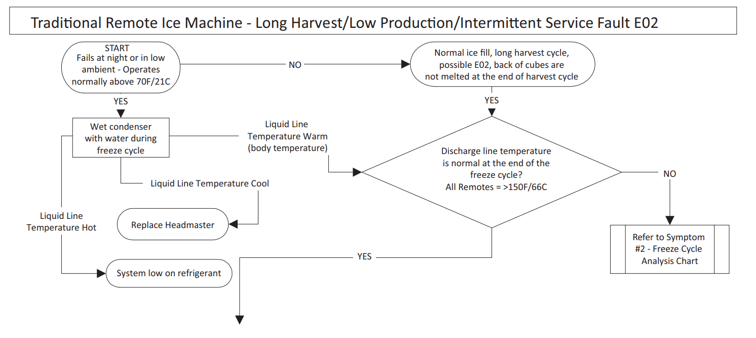
- Regardless of ambient and water temperatures, the freeze cycle discharge line temperature should be higher than 150°F (66°C) at the end of the freeze cycle.
PROCEDURE
- Navigate to Service/Diagnostics/Temperature Sensors/T2 Thermistor.
- Observe the discharge line temperature (T2) for the last three minutes of the freeze cycle and record on the table.
Water Regulating Valve
Problem (Freeze Cycle)
Valve not maintaining discharge pressure.
- Valve incorrectly set, dirty or defective. Adjust valve to correct discharge pressure for your model (refer to cycle times/24 hour productions charts), clean or replace valve.
Discharge pressure extremely high; Liquid line entering receiver feels hot
- Water regulating valve incorrectly set or not opening
- Insufficient water volume - undersized/kinked lines, mineral or scale buildup in lines.
Discharge pressure low, Liquid line entering receiver feels warm to hot
- Ice machine low on charge. Refer to “Total System Refrigerant Charge” on page 198.
Water pressure forces water regulating valve open
- Reduce incoming water pressure or install high pressure water regulating valve.
Final Analysis - Self-contained Air, Water & Remote Condenser Models
The column with the highest number of check marks identifies the refrigeration problem.
COLUMN 1 - HARVEST VALVE LEAKING
- Replace the valve as required.
COLUMN 2 - LOW CHARGE/TXV STARVING
Normally, a starving expansion valve only affects the freeze cycle pressures, not the harvest cycle pressures. A low refrigerant charge normally affects both pressures. Verify the ice machine is not low on charge before replacing an expansion valve.
- Add refrigerant charge to verify a low charge (air and water self-contained only). Do not add more than 30% of nameplate refrigerant charge. If the problem is corrected, the ice machine is low on charge. NOTE: Do not add charge to remote models. The symptoms of a remote low on charge will result in a safety long freeze in cool ambient temperatures. Check the liquid line temperature at the ice machine. The liquid line will be hot with a normal or below normal head pressure in freeze when the ice machine is low on refrigerant.
- Find the refrigerant leak. The ice machine must operate with the nameplate charge. If the leak cannot be found, proper refrigerant procedures must still be followed. Change the liquid line drier. Then, evacuate and weigh in the proper charge.
- If the problem is not corrected by adding charge, the expansion valve is faulty.
COLUMN 3 - TXV FLOODING OR REFRIGERANT OVERCHARGE
- A loose or improperly mounted expansion valve bulb causes the expansion valve to flood. Check bulb mounting, insulation, etc, before changing the valve. Verify refrigerant amount is correct by weighing recovered refrigerant before replacing a TXV.
COLUMN 4 - COMPRESSOR
- Replace the compressor. To receive warranty credit, the compressor ports must be properly sealed by crimping and soldering them closed.
SYMPTOM #3 & #4 - HARVEST PROBLEMS SELF‑CONTAINED AIR, WATER & REMOTE CONDENSER MODELS
- Definition of a harvest problem; At the end of a 3.5 minute harvest cycle the slab of ice is still contacting the evaporator. The slab of ice may or may not be removable by hand.
- Harvest problems can be split into two symptoms.
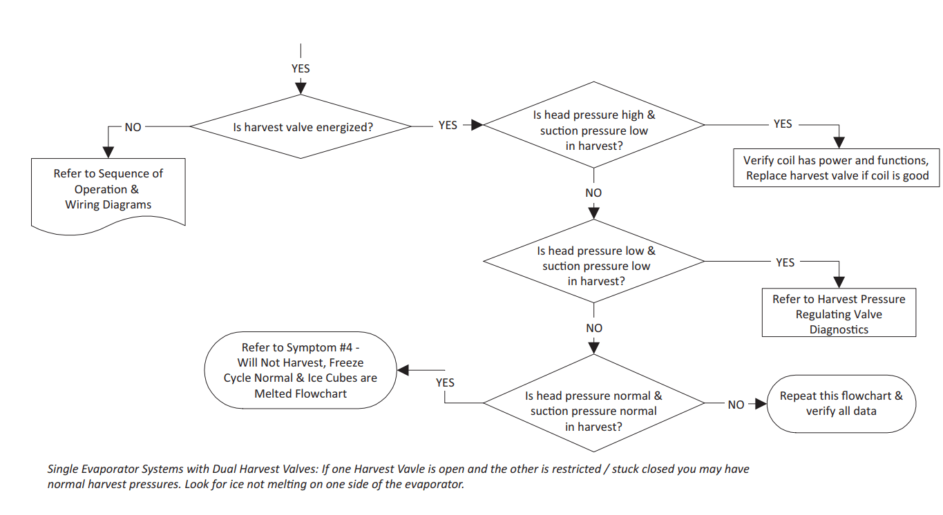
- Symptom 3 - Normal sheet of cubes at the end of the harvest cycle. Ice is difficult to remove from the evaporator by hand. Once removed the back of the cubes are square and show no signs of melting. This indicates a refrigeration problem. The source of the problem could be in the freeze or harvest cycle. Use the appropriate flow chart (in Troubleshooting) to determine the cause of the problem.
- Symptom 4 - Melted sheet of cubes at the end of the harvest cycle. Ice can be removed rather easily by hand. The back of the cubes are misshapen and melted. This indicates something is preventing the ice slab from releasing. Follow the appropriate flow chart (in Troubleshooting) to determine the cause of the problem. A manual cleaning procedure must always be performed when this problem is encountered.
SYMPTOM #3 - SELF-CONTAINED AIR OR WATERCOOLED
SYMPTOM #3 - REMOTE CONDENSER
SYMPTOM #4 - SELF-CONTAINED AIR, WATER-COOLED OR REMOTE