Installation Instructions
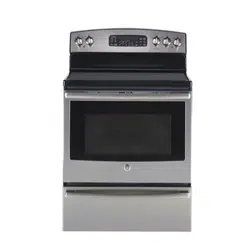
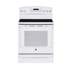
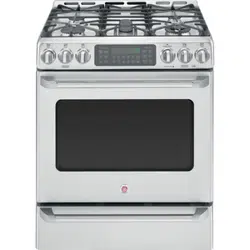
Free-Standing Electric Ranges
TOOLS YOU WILL NEED:
REMOVE PACKAGING MATERIALS:
Failure to remove packaging materials could result in damage
to the appliance. Remove all packing parts from oven, racks,
heating elements and drawer. Also, remove protective film
and labels on the outer door, cooktop and backguard.
NOTE: Cut the orange shipping ties from the power cord,
being careful not to damage the cord.
1
Questions? Call 1.800.561.3344 or Visit our Website at:
www.geappliances.ca
FOR YOUR SAFETY:
If you did not receive an anti-tip bracket with your purchase, call
1.800.561.3344 to receive one at no cost. For installation instructions
of the bracket, visit: www.geappliances.ca.
Anti-Tip Bracket
Kit Included
WARNING
—
Before beginning the installation,
switch power off at service panel and lock the service disconnecting means
to prevent power from being switched on accidentally. When the service
disconnecting means cannot be locked, securely fasten a prominent warning
device, such as a tag, to the service panel.
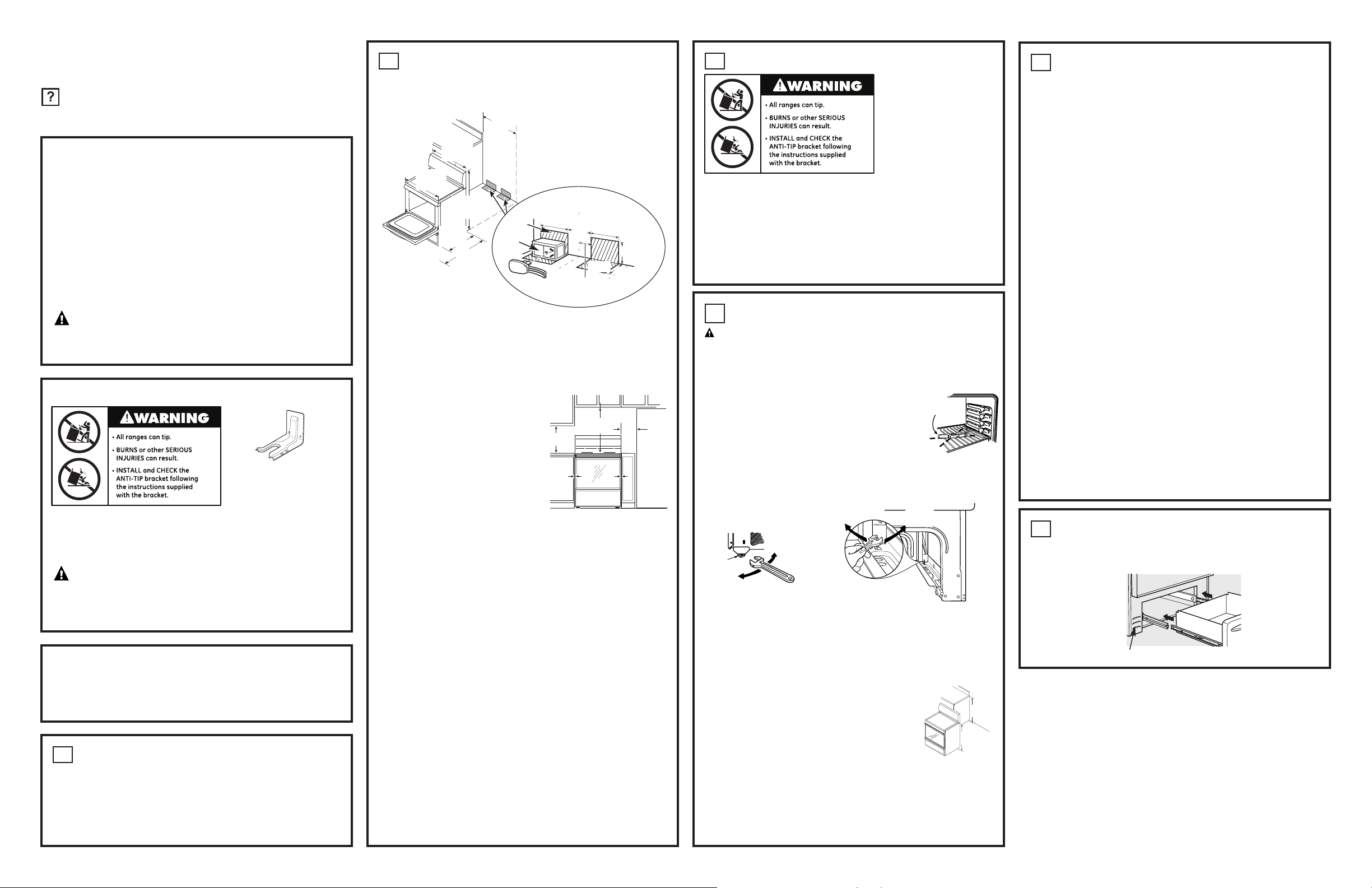
PREPARE THE OPENING
(FOR INDOOR USE ONLY)
See illustrations for all rough-in and spacing dimensions.
2
222D3619P003 31-21417 08-08 JRPrinted in Mexico
NOTE: Use a 1.2 m (4') power cord to prevent interference with
the storage drawer. Power cords 1.4 to 1.8 m (4
1
⁄2' to 6') long
may have to be dressed to allow for proper drawer closing.
MINIMUM DIMENSIONS BETWEEN
COOKTOP, WALLS AND ABOVE
THE COOKTOP:
A. The range must be placed with
12 mm (1⁄2") minimum clearance
at the back wall and side walls of
the cabinet. Make sure the wall
covering, countertop, flooring
and cabinets around the range
can withstand the heat (up to
93.3 ˚C/200˚F) generated
by the range.
B. Allow 76.2 cm (30") minimum
clearance between surface units
and bottom of unprotected wood
or metal cabinet, or allow a 60 cm (24") minimum when
bottom of wood or metal cabinet is protected by no less than
0.6 cm (1/4") thick flame retardant millboard covered with not
less than No 28 MSG sheet metal (.015"), .015" thick
stainless steel, .024" aluminum or .020" copper.
C. A 15.2 cm (6") spacing to surfaces less than 38.1 cm (15")
above the cooktop is recommended to reduce exposure
to steam, grease splatter and heat.
To reduce the risk of burns or fire when reaching over hot
surface elements, cabinet storage space above the cooktop
should be avoided. If cabinet storage space is to be provided
above the cooktop, the risk can be reduced by installing a
range hood that projects at least 12.7 cm (5") beyond the front
of the cabinets. Cabinets installed above the cooktop must be
no deeper than 33 cm (13").
Flooring under the range
Your range, like many other household items, is heavy and
can settle into soft floor coverings such as cushioned vinyl
or carpeting.
When moving the range on this type of flooring, it should be
installed on a 6 mm (1/4") thick sheet of plywood (or similar
material) as follows:
When the floor covering ends at the front of the range, the area
that the range will rest on should be built up with plywood to
the same level or higher than the floor covering. This will allow
the range to be moved for cleaning or servicing.
LEVEL THE RANGE
WARNING: Never completely remove the leveling leg
as the range will not be secured to the anti-tip device properly.
MODELS WITHOUT BAKING OR WARMING DRAWERS
A. Install the oven racks in the oven and position the range
where it will be installed.
B. Check for levelness by placing a spirit
level or a cup, partially filled with water,
on one of the oven racks. If using
a spirit level, take two readings—with
the level placed diagonally first in
one direction and then the other.
C. Remove the storage drawer, broiler drawer or kick panel.
The front leveling legs can be adjusted from the bottom
and the rear legs can be adjusted from the top.
D. Use an open-end or adjustable wrench to adjust
the leveling legs until the range is level.
E. Replace the drawer or panel.
MODELS WITH BAKING OR WARMING DRAWERS
A. Plug in the range.
B. Measure the height of your countertop
at the rear of the opening (X).
C. Adjust two rear leveling legs so that
the rear of cooktop is at the same height
as the counter (Y).
D. Slide unit into place.
E. Install oven racks in the oven and position the range where
it will be installed.
F. Check for levelness by placing a spirit level on one
of the oven racks. Take two readings—with the level
placed diagonally first in one direction and then the other.
G. Adjust front leveling legs until the range is level.
4
X
Y
Spirit level
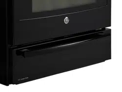
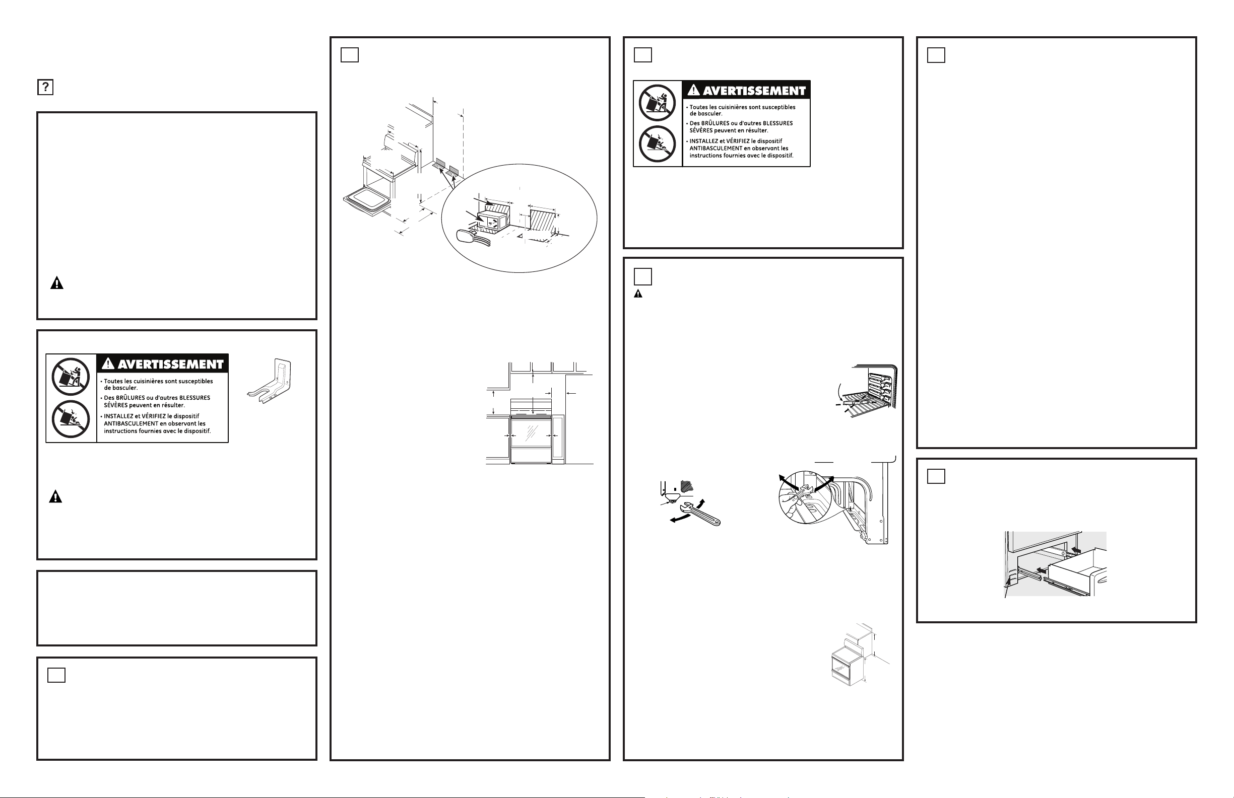
MODEL AND SERIAL NUMBER LOCATION
The rating plate is located above the drawer on the oven
frame or on the side of the drawer frame.
6
FINAL INSTALLATION CHECKLIST
• Check to make sure the circuit breaker is closed (RESET)
or the circuit fuses are replaced.
• Be sure power is in service to the building.
Note (on some models): If the clock flashes “bAd” and then
“LinE” with a loud tone, the neutral connection to the range is
miswired. Check the terminal block connections and/or house
wiring to correct.
• Check to be sure that all packing materials and tape have
been removed. This will include tape on metal panel under
control knobs (if applicable), adhesive tape, wire ties,
cardboard and protective plastic. Failure to remove these
materials could result in damage to the appliance once the
appliance has been turned on and surfaces have heated.
• Check to make sure that the door and drawer are parallel
to each other and that both operate smoothly. If they do not,
see the Owner’s Manual for proper replacement.
• Check to make sure that the rear leveling leg is fully
inserted into the Anti-Tip bracket and that the bracket
is securely installed.
OPERATION CHECKLIST
• Turn on one of the surface units to observe that the element
glows within 60 seconds. Turn the unit off when glow is
detected. If the glow is not detected within the time limit,
recheck the range wiring connections. If change is required,
retest again. If no change is required, have building wiring
checked for proper connections and voltage.
• Check to make sure the Clock (on models so equipped) display
is energized. If a series of horizontal red lines appear in the
display, disconnect power immediately. Recheck the range
wiring connections. If change is made to connections, retest
again. If no change is required, have building wiring checked
for proper connections and voltage. It is recommended that
the clock be changed if the red lines appear.
• Be sure all range controls are in the OFF position before
leaving the range.
5
BEFORE YOU BEGIN
Read these instructions completely and carefully.
•
IMPORTANT—Save these instructions for local inspector’s use.
•
IMPORTANT—Observe all governing codes and ordinances.
•
Note to Installer – Be sure to leave these instructions with Consumer.
•
Note to Consumer – Keep these instructions for future reference.
•
Skill level – Installation of this appliance requires a qualified
installer or electrician.
•
Proper installation is the responsibility of the installer.
•
Product failure due to improper installation is not covered under warranty.
WARNING—This appliance must be properly
connected by means of the supplied cord and plug. If your kitchen
does not have a receptacle, you must have one installed by a licensed
electrician.
Rating plate
ANTI-TIP DEVICE INSTALLATION
To reduce the risk of
tipping the range, the
range must be secured by
a properly installed anti-tip
bracket. See installation
instructions shipped with
the bracket for complete
details before attempting
to install.
To check if the bracket
is installed and engaged
properly, remove the storage drawer or kick panel and look underneath
the range to see that the leveling leg is engaged in the bracket. On
models without a storage drawer or kick panel, carefully tip the range
forward. The bracket should stop the range within 4 inches. If it does
not, the bracket must be reinstalled. If the range is pulled from the
wall for any reason, always repeat this procedure to verify the range
is properly secured by the anti-tip bracket. Never completely remove
the leveling legs or the range will not be secured to the anti-tip
device properly.
3
B
Both
Sides
C
A
C
A
•
Drill with 1/8" Bit
•
Safety Glasses
•
Adjustable Wrench
•
Tape Measure
•
Pliers
•
1/4" Nut Driver
•
Level
Rear leveling legs
(on some models)
Front leveling legs
(on some models)
Lower
range
Raise
range
Adjust
from
the top
Front of range
121.3 cm
(47
3
⁄4")
66 cm
(26
")
76.2 cm
(30")
116.8 cm
(46
")
78.4 cm
(30
7
⁄8
")
75.8 cm
(29
7
⁄8
")
Cord
Wall
Floor
17.7 cm
(7")
12.7 cm (5")
C of range
Outlet
box
5.7 cm
(2
1
⁄4")
19 cm
(7
1
⁄2")
19 cm
(7
1
⁄2")
8.9 cm
(3
1
⁄2")
Install the
outlet box
on either
side of the C
L
L
Leg
leveler
Lower
range
Raise range
Adjust from
the bottom
Instructions d’installation
Cuisinières électriques autonomes
OUTILS NÉCESSAIRES :
RETRAIT DU MATÉRIEL D’EMBALLAGE :
L’omission de retirer le matériel d’emballage risque d’endommager
l’appareil. Retirez toutes les pièces d’emballage du four, des grilles,
des éléments chauffants et du tiroir. Retirez aussi la pellicule protectrice et
les étiquettes de la porte extérieure, de la table de cuisson et du dosseret.
NOTE : Coupez les attaches oranges d’expédition du cordon
d’alimentation, en prenant bien soin de ne pas endommager le cordon.
1
Des questions? Appelez le 1.800.561.3344 ou consultez
notre site Web à :www.electromenagersge.ca
POUR VOTRE SÉCURITÉ :
Si vous n’avez pas reçu un dispositif antibasculement lors de votre achat,
composez le 1.800.561.3344 pour l’obtenir sans frais. Les installations
d’instruction du dispositif se trouvent sur le site electromenagersge.ca.
Dispositif
antibasculement
est fourni
AVERTISSEMENT
—
Avant de commencer
l’installation, coupez l’électricité au tableau de distribution et verrouillez le dispositif
de déconnexion de l’alimentation pour empêcher que le courant soit rétabli
accidentellement. S’il est impossible de verrouiller la déconnexion au tableau
de distribution, attachez fermement un avertissement, par exemple une étiquette,
au tableau de distribution.
PRÉPARATION DE L’OUVERTURE
(
POUR L’USAGE À L’INTÉRIEUR SEULEMENT
)
Voyez les illustrations pour toutes les dimensions brutes et les dégagements.
2
REMARQUE : Utilisez un cordon d’alimentation de 1,2 m (4 pi) pour
ne pas gêner le fonctionnement du tiroir de rangement. Les cordons
d’une longueur de 1,4 à 1,8 m (4
1
⁄2 à 6 pi) devront être assujettis
de façon à ne pas nuire à la fermeture du tiroir.
DIMENSIONS MINIMUMS ENTRE
LA SURFACE DE CUISSON, LES MURS ET
AU-DESSUS DE LA SURFACE DE CUISSON :
A.
La cuisière doit être placée en
conservant un dégagement minimum
de 12 mm (1⁄2 po) par rapport
au mur arrière et aux parois latérales
des armoires. Assurez-vous que
le revêtement des murs, les plans
de travail et les placards qui se trouvent
à proximité de la cuisinière peuvent
résister aux températures générées
par la cuisinière (jusqu’à 93,3 °C/200 °F).
B.
Laissez au moins 76,2 cm (30 po)
d’espace entre les éléments de surface
et le bas des placards en métal ou en bois non protégé, ou prévoyez un
minimum de 60 cm (24 po) à condition que le bas de l’armoire de bois ou de
métal soit protégé par un carton à l’enrouleuse ignifuge d’au moins 0,6 cm (1/4 po)
d’épaisseur, recouvert au minimum par l’un des matériaux suivants : tôle No 28
MSG (0,015 po), acier inox 0,015 po, aluminium 0,024 po ou cuivre 0,020 po.
C. Un espacement de 15,2 cm (6 po) par rapport aux surfaces situées
à moins de 38,1 cm (15 po) au-dessus de la table de cuisson est
recommandé afin de réduire l’exposition à la vapeur, la graisse
et la chaleur.
Lorsque vous essayez d’atteindre les armoires au-dessus de la table
de cuisson, vous pouvez éviter les risques de brûlure ou d'incendie
en attendant que les éléments de la table de cuisson se refroidissent,
les espaces d’armoires à rangement au-dessus de la table de cuisson
sont à éviter. S’il y a des armoires à rangement au-dessus de la table
de cuisson, les risques peuvent être moindres en installant une hotte
qui avance d’à peu près 12,7 cm (5 po) au-delà de l’avant des
armoires à rangement. Les armoires installées au-dessus de la table
de cuisson ne peuvent être plus profondes que 33,02 cm (13 po).
Plancher sous la cuisinière
Votre cuisinière, comme beaucoup d’autres appareils électroménagers,
est lourd et peut s’enfoncer dans votre couverture de plancher comme
un tapis ou une couverture de vinyle.
Quand vous bougez votre cuisinière sur ce genre de plancher,
vous devez l’installer sur une feuille de contreplaqué épais de 6 mm (1/4 po)
(ou de matériau semblable) de la manière suivante :
Quand la couverture de plancher se termine devant la cuisinière, la surface sur
laquelle repose la cuisinière doit être recouverte d’un contreplaqué de même
niveau ou plus épais que la couverture de plancher. Cela vous permet de
bouger la cuisinière pour la réparer ou pour nettoyer.
MISE À NIVEAU DE LA CUISINIÈRE
AVERTISSEMENT : N’ôtez jamais totalement une patte
de nivellement puisque la cuisinière ne sera plus fixée adéquatement
au dispositif antibasculement.
LES MODÈLES SANS TIROIR RÉCHAUD OU CUISSON
A. Installez les grilles dans le four et positionnez
la cuisinière à son emplacement définitif
.
B. Vérifiez que la cuisinière est de niveau
en mettant un niveau à bulle ou une tasse
partiellement remplie d’eau sur l’une des grilles
du four. Si vous utilisez un niveau à bulle,
vérifiez deux fois la première fois avec le niveau
en diagonale dans une direction et la deuxième
fois dans l’autre
.
C. Enlevez le tiroir de rangement, le tiroir de grillade ou le panneau
du seuil de porte. Les pieds de nivellement avant peuvent être
ajustés par le bas, et ceux de derrière par le haut ou par le bas
.
D. Utilisez une clé plate ou une clé à molette pour ajuster les pieds,
jusqu’à ce que la cuisinière soit de niveau
.
E. Remettez le tiroir ou le panneau
.
LES MODÈLES AVEC CUISSON OU TIROIR RÉCHAUD
A. Branchez la cuisinière.
B.
Mesurez la hauteur de votre plan de travail
à l’arrière de l’ouverture (X).
C.
Ajustez les deux pieds de nivellement arrière,
de sorte que l’arrière de la surface de cuisson
soit à la même hauteur que le plan de travail (Y).
D.
Glissez l’appareil en place.
E.
Installez les grilles dans le four et positionnez
la cuisinière à son emplacement définitif.
F.
Vérifiez que la cuisinière est de niveau en mettant un niveau à bulle
sur l’une des grilles du four. Vérifiez deux fois : la première fois avec
le niveau en diagonale dans une direction et la deuxième fois dans l’autre.
G.
Ajustez les pieds de nivellement avant jusqu’à ce que la cuisinière soit
de niveau.
4
X
Y
Niveau
à bulle
EMPLACEMENT DES NUMÉROS DE
MODÈLE ET DE SÉRIE
La plaque signalétique est située au-dessus du tiroir, sur le bâti du four
ou sur le côté du bâti du tiroir.
6
LISTE DE VÉRIFICATION FINALE
DE L’INSTALLATION
• Vérifiez que le coupe-circuit est fermé (RESET/RÉAMORCÉ) ou que les fusibles
du circuit ont été remis en place.
• Vérifiez que l’électricité marche dans le bâtiment.
Remarque (sur certains modèles) : Le clignotement du libellé « bAd »
puis « LinE » sur l’horloge, accompagné d’un fort son, est une indication
que le neutre est mal connecté. Vérifiez la rectitude des connexions au bloc
de jonction et/ou de l’installation électrique du domicile.
• Vérifiez que tout le matériel d’emballage et tous les rubans adhésifs ont été enlevés.
Ceux-ci comprennent le ruban adhésif sur le panneau en métal en dessous des
boutons de commande (le cas échéant), tous les rubans adhésifs, les attaches en
métal, les cartons et les protections en plastique. Si vous n’enlevez pas ce matériel,
la cuisinière pourrait être endommagée quand elle est allumée et que ses surfaces
sont chauffées.
• Vérifiez que la porte et le tiroir sont parallèles l’une à l’autre et qu’ils fonctionnent
tous les deux correctement. Dans le cas contraire, reportez-vous au Manuel
de l’utilisateur pour savoir comment les remplacer.
• Vérifiez que le pied de nivellement arrière est complètement inséré dans le dispositif
antibasculement, et que ce dispositif est installé de façon sûre.
LISTE DE VÉRIFICATION DU FONCTIONNEMENT
• Allumez un des éléments de surface pour vérifier que l’élément se met
à briller dans les 60 secondes qui suivent. Éteignez l’élément après avoir
fait cette observation. S’il ne brille pas dans les 60 secondes, vérifiez
de nouveau les raccords électriques de la cuisinière. S’ils doivent être
modifiés, testez de nouveau. Si aucun changement n’est nécessaire, faites
vérifier les raccords et le voltage de l’installation électrique du bâtiment.
• Vérifiez que l’afficheur de l’horloge (pour les modèles qui en ont une) est
activé. Si une série de lignes horizontales apparaît à l’afficheur, coupez
l’électricité immédiatement. Revérifiez les raccords électriques de la
cuisinière. Si des modifications sont apportées aux raccords, testez de
nouveau. Si aucun changement n’est nécessaire, faites vérifier les raccords
et le voltage de l’installation électrique du bâtiment. Si des lignes rouges
apparaissent dans l’horloge, nous vous recommandons de la changer.
• Assurez-vous que toutes les commandes de la cuisinière sont à la position
OFF (ARRÊT) avant de vous en éloigner.
5
AVANT DE COMMENCER
Lisez attentivement ces instructions.
•
IMPORTANT—
Conservez ces instructions pour l’usage
de l’inspecteur local.
•
IMPORTANT—
Observez tous les codes et règlements en vigueur.
•
Remarque pour l’installateur – Veillez à laisser ces instructions avec
le consommateur.
•
Remarque pour le consommateur – Conservez ces instructions pour un usage
ultérieur.
•
Niveau de compétence – L’installation de cet appareil doit être réalisée par
un installateur ou électricien qualifié.
•
L’exactitude de l’installation est sous la responsabilité de l’installateur.
•
Une panne du produit suite à une mauvaise installation n’est pas couverte
par la garantie.
AVERTISSEMENT
—
Cet appareil doit être
connecté correctement avec le câble et la prise électrique fournis. Si votre cuisine
n’a pas de réceptacle pour la connexion, vous devez en faire installer un par
un électricien agréé.
Plaque signalétique
INSTALLATION DU DISPOSITIF
ANTIBASCULEMENT
Pour réduire le risque
de basculement, la
cuisinière doit être
arrimée à un dispositif
antibasculement
correctement installé.
Lisez les instructions
d’installation détaillées
qui sont livrées avec
le dispositif avant de
procéder à l’installation.
Pour vous assurer de l’installation et fonctionnement adéquats du dispositif, retirez le tiroir
de rangement ou le panneau de protection et observez sous la cuisinière que la patte de
nivellement est engagée dans le dispositif. Sur les modèles dotés d’un tiroir de rangement
ou d’un panneau de protection, basculez avec précaution la cuisinière vers l’avant.
Le dispositif devrait arrêter la cuisinière dans moins de 4 pouces. Si ce n’est pas le cas,
le dispositif doit être réinstallé. Si la cuisinière doit être éloignée du mur pour une raison
quelconque, répétez toujours cette procédure pour vous assurer que la cuisinière est
bien arrimée au dispositif antibasculement. N’ôtez jamais totalement les pattes de nivellement
puisque la cuisinière ne sera plus fixée adéquatement au dispositif antibasculement.
3
B
Deux
côtés
C
A
C
A
•
Perceuse avec foret
de 3,2 mm (1/8 po)
•
Lunettes protectrices
•
Clé à molette
•
Ruban à mesurer
•
Pince
•
Tournevis à douille
1/4 po
•
Niveau à bulle
66 cm
(26
po)
76,2 cm
(30 po)
19 cm
(7
1
⁄2 po)
19 cm
(7
1
⁄2 po)
Baisser la
cuisinière
Elever la
cuisinière
Réglez
d’en
haut
Pieds arrières de nivellement
(sur certains modèles)
Pieds devants de nivellement
(sur certains modèles)
Avant de la cuisinière
Pied de
nivellement
Baisser la
cuisinière
Élever la cuisinière
222D3619P003 31-21417 08-08 JRImprimé au Mexique
12,7 cm (5 po)
5,7 cm
(2
1
⁄4 po)
8,9 cm (3
1
⁄2 po)
Installez le
boîtier de
prise de l’un
ou l’autre
côté du C
L
C
L
de la cuisinière
Cordon
d’alimentation
Mur
Plancher
Boîtier
de
prise
Réglez
d’en
bas
17,7 cm
(7 po)
121,3 cm
(47
3
⁄4 po)
116.8 cm
(46
po)
78,4 cm
(30
7
⁄8
po)
75,8 cm
(29
7
⁄8
po)