Loading ...
Loading ...
Loading ...
8
WARNING: Loudspeaker terminals are hazard-
ous live and present a risk of electric
shock. For additional instruction on
making Loudspeaker Connections con-
tact your McIntosh Dealer or McIn-
tosh Technical Support.
13. Attach the Terminal Connections Cover to the
MC611 Rear Panel with the previously removed
Screws. Refer to figure 6.
14. Connect the MC611 power cord to an active AC
outlet.
ance connection. Refer to “General Information” Note
3 on page 2 for additional information.
WARNING: Loudspeaker terminals are hazardous
live and present a risk of electric shock.
For additional instruction on making
Loudspeaker Connections contact your
McIntosh Dealer or McIntosh Techni-
cal Support.
9. Attach the Terminal Connections Cover to the
MC611 Rear Panel with the previously removed
Screws. Refer to figure 5.
10. Connect the MC611 power cord to an active AC
outlet.
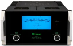
Spade Lug or Wire Connections:
11. Locate the Terminal Connections Cover from the
inside of the MC611 shipping carton. Insert the
just prepared Loudspeaker hookup cables thru the
cover opening on the right side. Refer to figure 6.
12. Connect the Loudspeaker hookup cables to the
MC611 Negative Output Terminal and Positive
Output Terminal indentified as 2Ω (ohms), 4Ω
(ohms) or 8Ω (ohms) connection to match the
impedance of the Loudspeaker, being careful to
observe the correct polarities. Insert the spade
lug connector or prepared section of the cable end
into the terminal side access hole, and tighten the
terminal cap until the cable is firmly clamped into
the terminals so the lugs or wire cannot slip out.
Refer to figures 7 and 8.
Note: The illustration in figure 6 is connections for
8Ω (ohms) Loudspeakers.
If the Loudspeaker’s impedance is in-between
the available connections, use the nearest lower
impedance connection. Refer to “General Informa-
tion” Note 3 on page 2 for additional information.
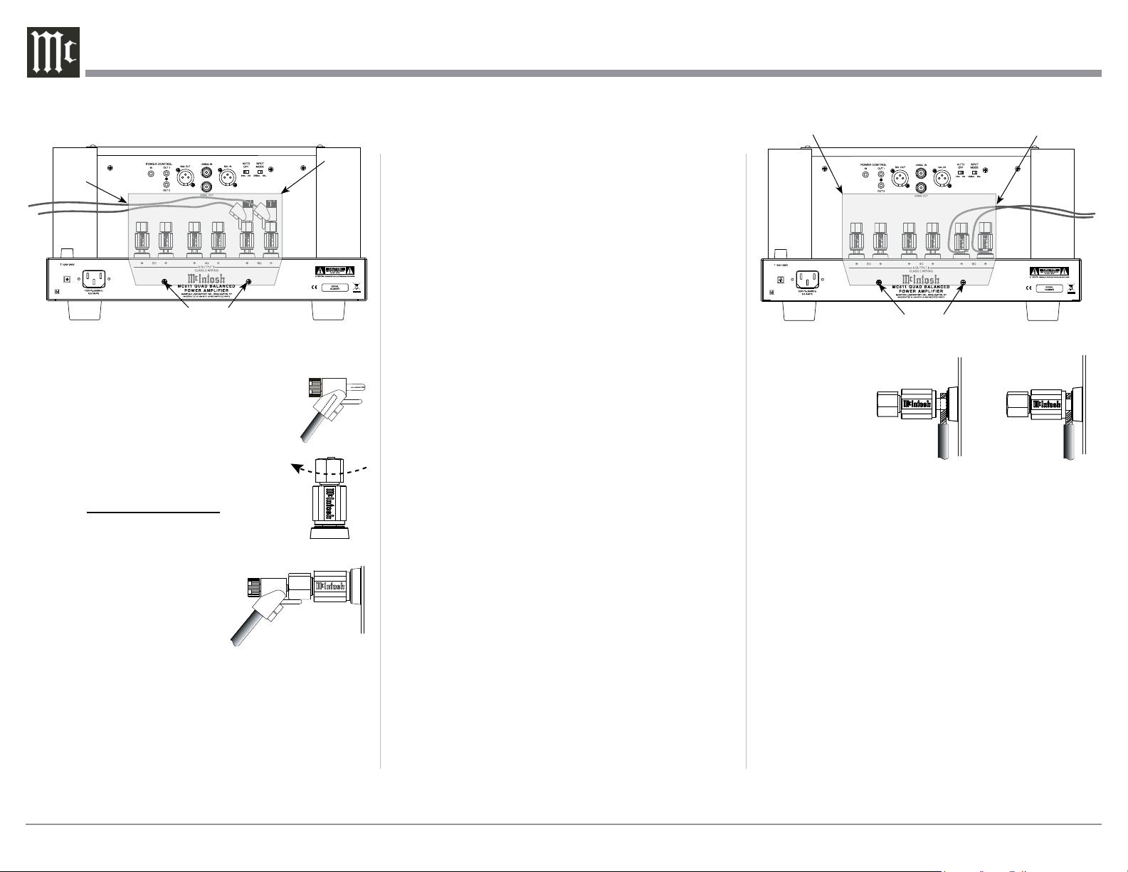
cover opening on the left side. Refer to figure 5.
6. Attach the previously prepared bare wire cable ends
into the banana plugs and secure the
connections. Refer to figure F.
7. Rotate the top of the Output Terminal
Post clockwise until it is nger tight.
Refer to gure G. Then using the Mc-
Intosh Wrench, rotate the top of the
Output Terminal one quarter of a turn
(90° ). Do not over tighten. Refer to
gure E.
8. Referring to figure H, connect the
Loudspeaker hookup
cables with banana plugs
into the hole at the top of
the MC611 Negative and
Positive Output Terminals.
The terminals are indenti-
fied as 2Ω (ohms), 4Ω (ohms) or 8Ω (ohms) connec-
tion to match the impedance of the Loudspeaker,
being careful to observe the correct polarities.
Note: The illustration in figure 5 is connections for
8Ω (ohms) Loudspeakers.
If the Loudspeaker’s impedance is in-between the
available connections, use the nearest lower imped-
Output Terminals and How to Connect
Figure 7
Figure 8
Figure F
Figure H
Figure F
Figure H
Figure G
Figure 5 (Inside USA and Canada)
Cover Screws
Cover
Cover Opening
Figure 6 (Outside USA and Canada)
Cover Openings
Cover Screws
Cover
Loading ...
Loading ...
Loading ...