Loading ...
Loading ...
Loading ...
15
into what is called
an optimum load.
This optimum load
may vary consider-
ably from what a
loudspeaker re-
quires. In the case
of more than one
loudspeaker con-
nected in paral-
lel, the load to the
power amplifier
may drop to two
ohms or even less.
A power amplifier
connected to a load
that is lower than
optimum,
causes
more output
current to
flow, which results in extra heat being gener-
ated in the power output stage. This increase
in temperature will result in a reduced life
expectancy for the amplifier.
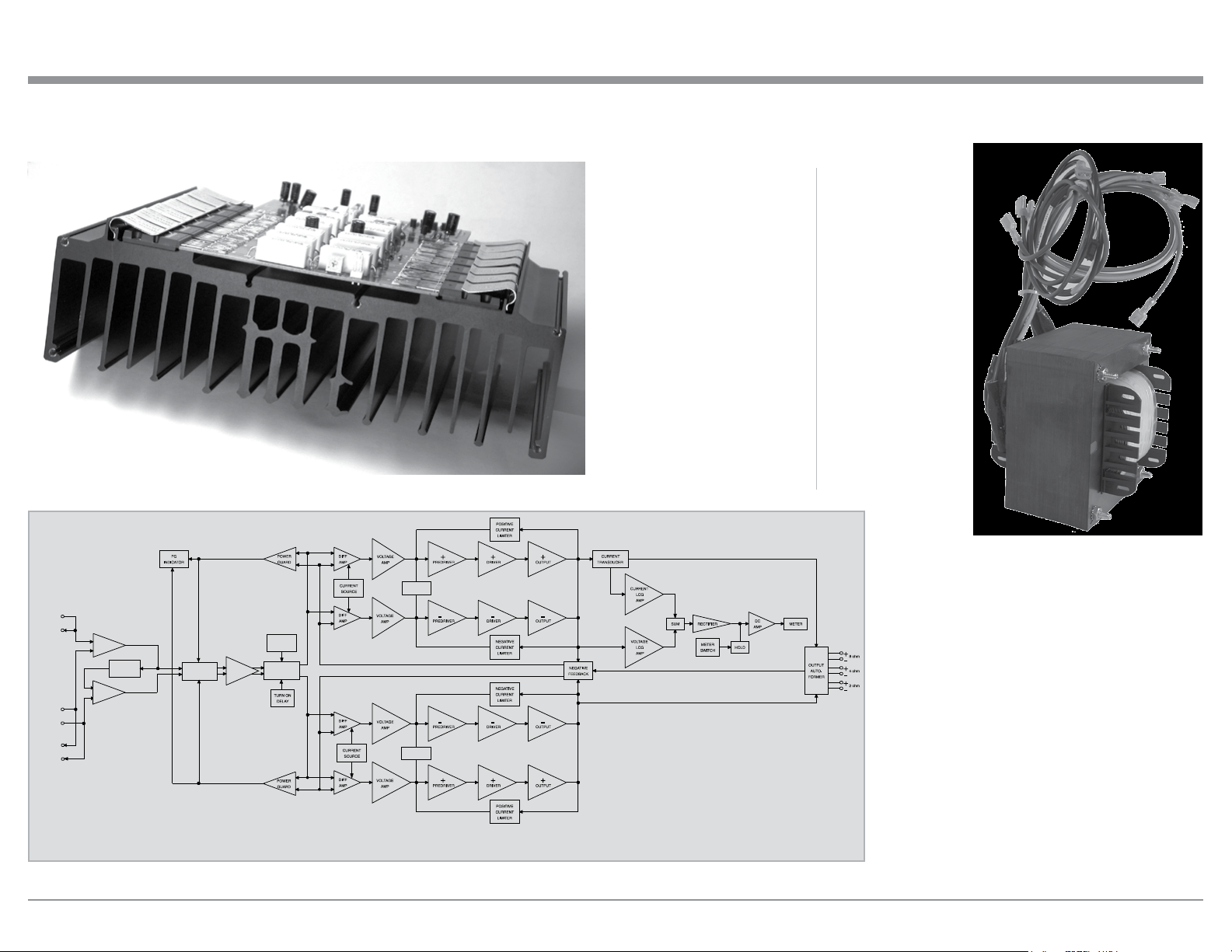
The special Balanced Winding Autoformer
creates an ideal match between the power am-
plifier output stage and the loudspeaker. Refer
to figure 17.
There is absolutely no performance limita-
tion with an Autoformer. Its frequency re-
sponse exceeds that of the output circuit itself,
and extends well beyond the audible range. Its
distortion level is so low it is virtually impos-
sible to measure.
expertise of McIntosh in the
design and manufacturing of
autoformers is legendary in
the high fidelity industry.
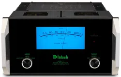
The high efficiency circuit
design of the MC611 contrib-
utes to low operating tem-
peratures. More than 1400
square inches of heat sink
area keep the MC611 operat-
ing safely with convection
cooling. No fans are needed.
Refer to figure 15.
Autoformers
All solid state power ampli-
fier output circuits work best
Technical Description
Block Diagram
of the
Power Amplifier
Figure 16
ThermalTrak
DC BIAS
OUTPUT
MUTE
THERMAL
SENSORS
BALANCED
AMP
POWER GUARD
ATTENUATOR
INPUT MODE
SWITCH
-
AMP
+
AMP
UNBALANCED
OUTPUT
UNBALANCED
INPUT
BALANCED
INPUT
BALANCED
OUTPUT
+
+
-
-
ThermalTrak
DC BIAS
Fig ure 17
Figure 15
Loading ...
Loading ...
Loading ...