
Owner’s Manual
Delta MONO
Monaural Amplifier

2
Contents
Welcome to the Classé family ..........................................................................3
Unpacking and Placement ............................................................................... 4
Special Design Features ...................................................................................6
Front Panel .......................................................................................................7
Rear Panel ........................................................................................................9
Installation .....................................................................................................15
CAN-Bus ........................................................................................................ 17
Care and Maintenance ................................................................................... 20
Troubleshooting .............................................................................................21
Specifications .................................................................................................23
Dimensions .................................................................................................... 25

3
Welcome to the Classé family
Congratulations on your purchase of a Classé amplier. It is the result of many
years of design experience, and we are sure that you will enjoy it for many years
to come.
We value our relationship with our customers. Please allow us to stay in touch
with you by registering now. Doing so will enable us to let you know about any
possible future upgrades or updates that might become available for your Classé
component.
You can register online at https://classeaudio.com.
Please take a few moments now to register your new
Classé amplifier and record your serial number for future
reference
a word about installation Every eort has been made to make the Classé Delta MONO simple and
straightforward to install and use.
It may be placed on a shelf, in a cabinet or on the oor near the speaker(s). As
with all ampliers, the Delta MONO generates some heat and care should be
taken to allow adequate ventilation.
e size and shape of your room, its acoustics, and the associated equipment
you have chosen to use with your amplier all inuence the performance of your
system.
For this reason, we strongly encourage you to have your
system installed and calibrated by your dealer, whose
experience, training, and specialized equipment can
make a profound difference in the final performance of
the system.

4
Unpacking and Placement
unpacking your amplifier Carefully unpack your power amplier according to the supplied instructions,
and remove all accessories from the carton. Please take care when lifting the
amplier, as it is extremely heavy with weight somewhat concentrated near the
front right corner.
Important! Keep all packing materials for future transport of your
Classé amplifier. Shipping your new component in
anything other than its purpose-designed packing material
may result in damage that is not covered by the warranty.
Important! Remove the protective film from the meter lens slowly to
reduce the chance that static will build up inside, causing
a deflection of the meter’s pointer. If this happens, the
pointer may settle to its nominal zero position over a
short time on its own, but an anti-static wipe has been
included in the accessories pack which can be used to
discharge the static. Gently swiping it across the lens
surface should remove any built up static charge from the
meter assembly.
placement Many installations will utilize an equipment rack, although a shelf, a cabinet or
the oor near the speaker(s) are acceptable alternatives. In any case, take care to
position it well away from source components and preamp/processors, which
may be sensitive to the amplier’s electromagnetic elds.
Note that adequate clearance for the AC cord and connecting cables
must be left behind the amplier. We suggest leaving six inches (15 cm)
of free space behind your power amplier to allow all cables sucient
room to bend without crimping or undue strain.
unit’s temperature An important note about letting the unit come to room temperature:
e amplier has built-in circuitry that will prevent it from being
powered on if it is too cold. If the amp has been delivered on a cold
day it should be allowed to acclimate to room temperature before being
plugged in.
ventilation Your Classé power amplier generates a certain amount of heat in the course of
normal operation. Avoid placement on soft surfaces that would restrict airow
around the unit (such as plush carpeting). Leave at least two inches (5 cm) of
clearance in front and above the amplier and six inches (15 cm) behind the
amplier to allow the active cooling system to function properly. If installing the
amplier in a cabinet, make sure that an opening at least 4” x 4” (10 cm x 10
cm) is provided opposite the fan exhaust area on the amplier rear panel.
5
custom installations Drawings are included in this manual to facilitate special installations and
custom cabinetry (see the section Dimensions). Contact your Classé dealer for
more information.
serial number e serial number for your power amplier is found on the rear of the unit.
Please note and record this number on the page entitled Important Safety
Instructions for your future reference.
operating voltage e operating voltage of your Delta MONO is indicated on the rear of the unit.
Do NOT connect the amplier to AC mains power of dierent line voltage.
Warning: There are no user-serviceable parts within the unit. Please
refer any problems to an authorized Classé service center.
e amplier can easily be powered by a normal 15 or 20-amp AC mains line.
If other devices are also powered from the same AC line, their additional power
consumption should be taken into account.
warm up/break-in period Your new Classé power amplier will deliver outstanding performance
immediately. However, you should expect to hear it improve somewhat as
it reaches its normal operating temperatures and its various components
“break-in.” It has been our experience that the greatest changes occur within the
rst 72 hours, as the amplier reaches thermal equilibrium and the capacitors
fully form. After this initial break-in period, the performance of your new
amplier should remain quite consistent for years to come.
please read this manual… Please take a few minutes to review this manual, and to familiarize yourself with
your new amplier. We understand that you are anxious to plug everything in
and get started. However, reading this manual and following the advice it gives
will ensure that you get all the benets you deserve from having purchased such
a ne piece of equipment.

6
Special Design Features
highly refined
circuit design
is Classé amplier utilizes our latest technology, implemented with the
highest quality parts. A combination of careful part selection and circuit layout
combined with an extended class A operating area enables superior performance
under all conditions. It delivers enormous power into low-impedance loads and
achieves extremely low distortion throughout the audio band, most notably
maintaining its low-distortion prole even at high frequencies. e result is
an engaging sound without listener fatigue that will lead to countless hours of
listening enjoyment.
extensive listening tests Excellent measured performance is to be expected in world-class products, and
Classé products deliver that performance. However, experience has shown that
technical excellence alone is insucient to guarantee subjectively musical results.
For this reason, all Classé products are laboriously ne-tuned during the
development process by carefully controlled listening tests. Our ears are still
some of the nest test instruments available, and nicely complement even the
best engineering test equipment. We rely on careful listening tests, which we
view as a necessary complement to the solid engineering you should rightly
expect from Classé.
extraordinary longevity e Classé Design team has accumulated vast experience in what works well over
the long term.
By using only the highest quality parts to begin with, and then using them in
an informed way as a result of both accelerated aging tests and actual long-
term experience, we are able to design and manufacture products which we are
condent will stand the test of time.
We are condent that your new Classé amplier will give you many years of
trouble-free reliability and musical enjoyment, just as previous Classé products
have given their owners.
robust protection Finally, your new Classé amplier incorporates a variety of protection circuits, all
designed to protect both the amplier and your loudspeakers against dangerous
fault conditions. Signicantly, these protection circuits do not intrude upon
or limit the normal performance of the amplier; rather, they simply put the
amplier into protection mode when confronted with abnormal conditions.
ese conditions include:
• output overload and short circuit protection
• DC oset
• excessive operating temperatures
Some conditions, such as DC oset, may be corrected up to a point
automatically in the amplier while others will result in the amplier switching
itself o. In such a case, the Standby LED status indicator will blink red until
the fault can be righted and the amplier is reset by pressing and holding the
standby button for at least ve seconds.
7
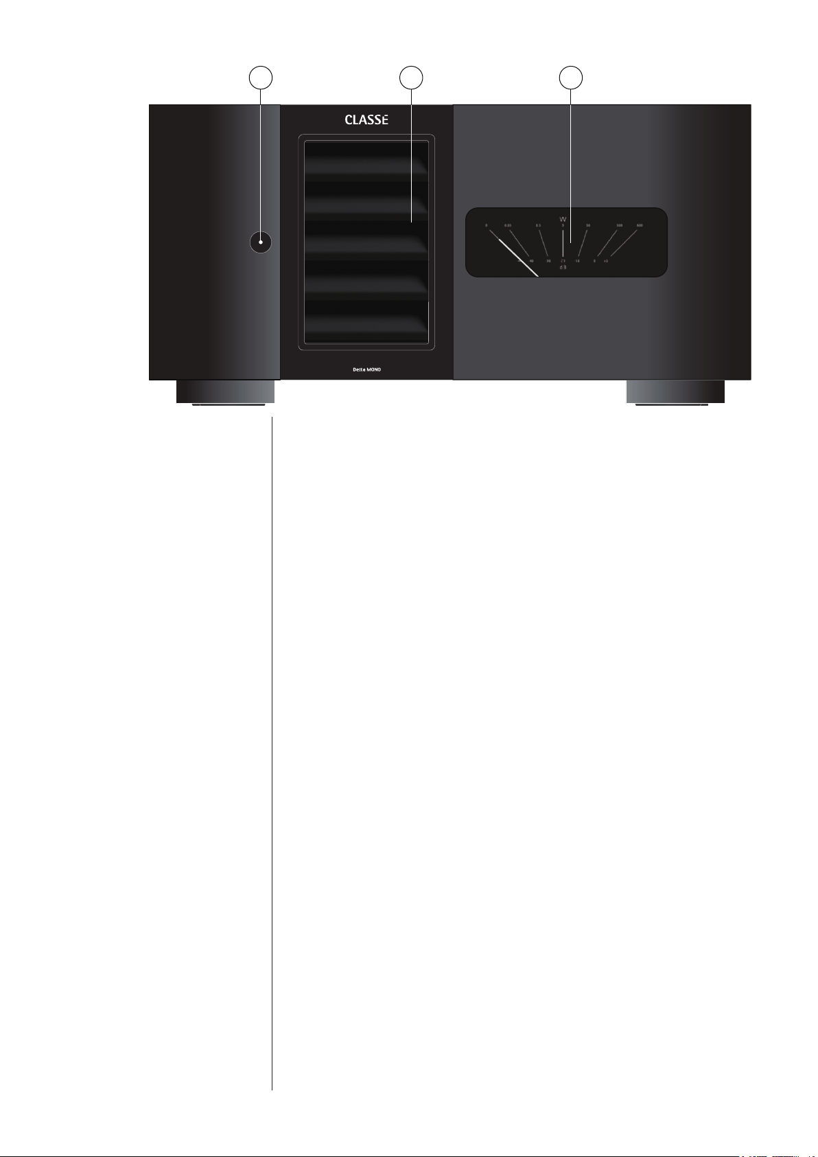
Front Panel
1 Standby/ON Button & Status Indicator LED
e front panel Standby button will toggle the amplier between
operate, its fully operational state, and a standby mode. (See also Wake on
Network).
e current state of the amplier is indicated by the LED status indicator
in the Standby button. e state of this LED indicates the following:
• on (red) = standby
• slow ashing (white) = initialization
• on (white) = operate
• ashing (red) = protection circuit(s) engaged
• ashing (green) = CAN identify mode
• ashing (orange) = error during update
When in standby, the amplier’s gain stages are powered down. Only a
small power supply and control circuit remain on, consuming relatively
little power. Fortunately, since the output stages by their nature conduct a
great deal of current, they warm up and sound their best very quickly.
If you are not going to use the amplier for an extended period of time, we
suggest you disconnect it from the AC mains.
Also, it is a good practice to physically disconnect any and all valuable
electronics from the AC mains during electrical storms, as a lightning
strike anywhere near your home can put a tremendous surge on the AC
mains that can easily damage any piece of electronics, no matter how well
designed and protected. e best protection in the case of severe electrical
storms is to simply remove the electronics from any connection with the
power grid.
1 3 2

8
Caution! If you see the Standby LED indicator blinking red, please
check that all external connections are cleanly made
and secure. If no fault is immediately obvious, try to
reset the amplifier by pressing and holding the standby
button. If the unit does not reset or continues to enter
protection mode, please call your authorized Classé
dealer for assistance.
2 ICTunnel
™
Air Intake
e Intelligent Cooling Tunnel removes heat from the amplier by pulling
cool air through the intake on the front panel. To ensure the proper
operation of the cooling system, be careful to keep the area around the air
intake on the front panel free of obstructions.
3 Output VU Meter
e output meter shows output power in Watts into an 8 ohm load and
provides a good relative indication of output in dB. A good rule of thumb
is that when the pointer is below/left of vertical the amplier is operating
in class A.
e backlight of the VU meter may be adjusted to three dierent
brightness levels or turned o. To adjust the brightness level, with the
amplier in standby, press and hold the standby button for approximately
5 seconds. e backlight will begin cycling through its brightness levels.
When the desired brightness is reached, release the button.
9
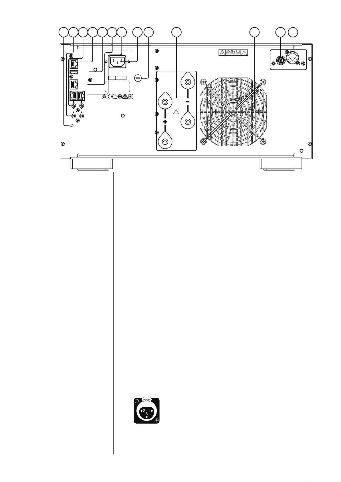
Rear Panel
e following descriptions are intended as a quick reference, should you have
any questions about your new product. Please see the next section (entitled
Installation) for specic advice on incorporating your new amplier into your
system.
1 Balanced (XLR) Input
Balanced audio interconnections were originally developed for the
telephone and more recently have been used in the professional audio
world for preserving the delicate nuances of extremely small microphone-
level signals. For many years now, they have also been used by
performance-oriented companies such as Classé to preserve every nuance
of the nest audio recordings in your collection.
Technically, balanced audio interconnections provide two distinct benets:
they double the signal’s strength as it travels from one component to the
next, increasing the potential Signal-to-Noise ratio by 6 dB; they also do
an excellent job of rejecting noise and interference that might otherwise be
picked up between the components. If executed as in the Delta MONO
with a high degree of symmetry between the inverting and non-inverting
signal paths, balanced connections can oer the best performance.
For this reason, we strongly recommend using the balanced analog
interconnections between your Classé components wherever possible.
e pin assignments of these XLR input connectors are:
Pin 1: Signal ground
Pin 2: Signal + (non-inverting)
Pin 3: Signal – (inverting)
Connector ground lug: chassis ground
ese pin assignments are consistent with the standard adopted by the
Audio Engineering Society (AES14-1992).
RS 232
CAN BUS
IN OUT
ETHERNET
UPDATE
HOST
TRIGGER
IR
100-120~
220-240~
T6.3AH 250V
T3.15AH 250V
INPUT
OUTPUT
CLASS 2 WIRING
AUTO-STANDBY
THIS DEVICE COMPLIES WITH PART 15 OF THE FCC RULES.
OPERATION IS SUBJECT TO THE FOLLOWING TWO CONDITIONS:
(1) THIS DEVICE MAY NOT CAUSE HARMFUL INTERFERENCE, AND
(2) THIS DEVICE MUST ACCEPT ANY INTERFERENCE RECEIVED,
INCLUDING INTERFERENCE THAT MAY CAUSE UNDESIRED OPERATION.
CAUTION! TO REDUCE THE RISK OF ELECTRIC SHOCK, GROUNDING
OF THE CENTRE PIN OF THIS PLUG MUST BE MAINTAINED
ATTENTION! POUR RÉDUIRE LE RISQUE DE CHOC ÉLECTRIQUE
LA FICHE CENTRALE DE LA PRISE DOIT ÊTRE
BRANCHÉE POUR MAINTENIR LA MISE À LA TERRE
8 4 9 10 5 6 7 3 1 2 12 13 11

10
If you are using your Classé power amplier with a Classé preamplier/
processor, you’re all set – just remove the supplied shorting pins (between
Pins 1 and 3) from the amplier’s XLR connector(s), take standard
balanced interconnect cables and plug them in.
If you are using another brand of preamplier or processor, please refer to its
operating manual to verify that the pin assignments of its output connectors
correspond to those of your amplier. If not, have your dealer obtain cables
with the appropriate output pin connecting to the equivalent input pin.
2 Single-Ended (RCA) Input
Single-ended cables using RCA connectors are the most common form
of analog connection used in consumer electronics. When implemented
carefully and with use of high quality interconnecting cables, this standard
can provide excellent performance. Classé has gone to extraordinary eort
to ensure that the single-ended (RCA) inputs of your power amplier
perform exceptionally well.
When using single-ended (RCA) inputs: to reduce the potential
to conduct noise, be sure to leave the shorting pins in place
between pins 1 and 3 of the XLR connector.
3 Speaker Outputs
e Delta MONO is designed to accommodate the impedance range of all
commercially available loudspeakers. Your dealer is in a good position to
advise which and/or how many ampliers are suitable for your particular
loudspeakers.
To facilitate bi-wiring, two pairs of high-quality ve-way binding posts
are provided on the amplier. ese connectors are made of rhodium-
plated copper and designed with a feature called Torque-Guard, which
ensures the optimum contact pressure to mate with your speaker wire
connector lugs without allowing the connector to be over-tightened. As
you tighten them, they will reach the proper torque and therefore act like
a torque wrench with click sounds indicating that the proper torque has
been reached.
In practice, bi-wiring involves connecting two (preferably identical) sets
of speaker cables between each amplier channel and its corresponding
loudspeaker. In many cases, the benet is a subjectively improved level of
clarity and detail from the speaker, as a result of being able to feed the two
separate sections of its crossover and driver complement with identical, yet
separate signals.
(Many high quality loudspeakers also oer two sets of connections on their
speakers. Generally, one set of the connections on the loudspeaker feeds the
portion of the speaker’s crossover network that supplies the woofer with its
signal; the other set of connections connects to the portion of the crossover that
supplies the rest of the speaker with the midrange and high frequencies.)
Although the binding posts on your Classé amplier will accept bare wire
connections, we strongly recommend the use of high quality spade or hook
lugs, crimped onto the ends of your speaker wires. Using high quality
connectors will ensure that your speaker connections do not gradually
deteriorate from fraying and oxidizing bare wires. It also helps prevent
accidental short-circuits from poorly-terminated connections.
11
4 Classé CAN-Bus Control Ports
ese RJ-45 connectors are reserved for control and communication
applications using a Classé implementation of the Controller Area
Network (CAN) Bus specication. Refer to the CAN-Bus section located
later in this manual for more information.
5 IR Input and Output
Your Classé amplier includes two
1
/8
th
-inch mini mono-jacks in order to
support the IR remote controls that are ubiquitous today. IR commands
exist for toggling the amplier between operate and standby, as well as
discrete command codes for either operate or standby. ese codes may be
used in “macros” for sophisticated remote control systems, facilitating the
control of the amplier in the larger context of a complete system.
Actually, this IR Input and Output description is a bit of a misnomer: the
input supplied to these plugs is electrical in nature, not IR. It is obtained by
using standard IR receivers, distribution ampliers, and emitters (available
from your dealer) to translate the remote’s ashes of infrared light into
corresponding pulses of electricity. e big advantages here include being
able to easily route the signals anywhere they might need to go, and the
reliability of a solid electrical connection.
Since an IR distribution system such as your dealer may design for you
usually must control many products, your amplier includes both an IR
input (for the control of this product) and an IR output (so as to pass
along the same signal to the next product). is allows you to “daisy chain”
your control wires from one product to the next.
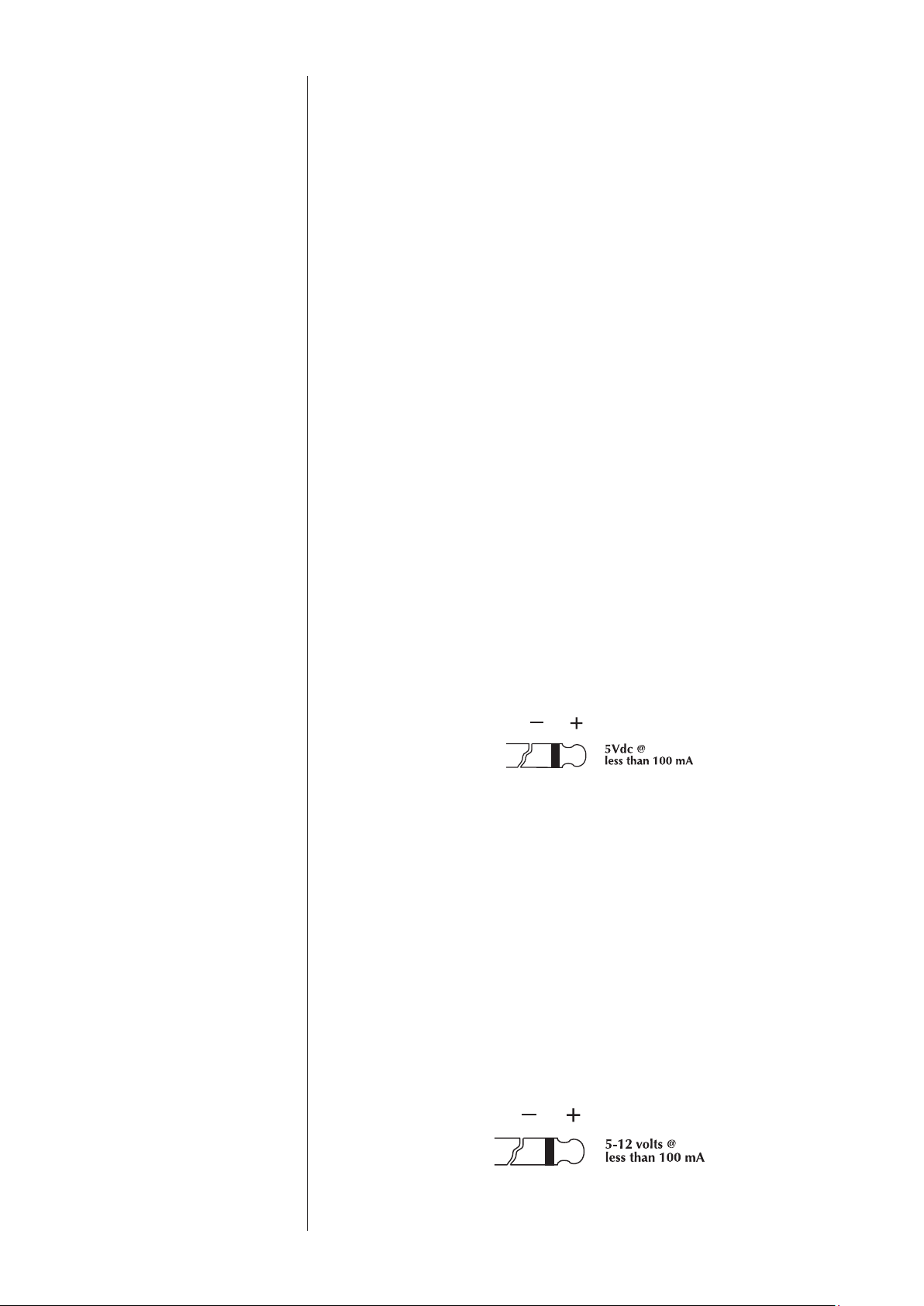
e amplier is designed to respond to IR commands of 5 Volts DC, with
the tip of the mini-plugs dened to be “positive” relative to the shank of
the plug.
6 DC Trigger Input and Output
Many audio/video preampliers can supply a DC control voltage to
associated equipment in order to induce desired behavior. Your Classé
amplier can take advantage of these capabilities in order to be switched
between operate and standby automatically, perhaps in concert with the
preamp/processor itself.
Two
1
/8
th
-inch mini mono-jacks provide this remote-controlled turn-on
(that is, toggling between operate and standby) of the amplier. ese jacks
provide a simple pass-through of the control voltage from one to the other,
allowing you to “daisy-chain” a series of ampliers quite easily.
e remote trigger will be operated by the presence of 5–12 Volts DC,
with tip polarity as shown below:

12
7 Auto Standby / Wake on Network
e Delta MONO employs power saving features to ensure that it
consumes a minimal amount of power while not in use.
Auto Standby will switch the amplier o if no audio signal is present for
approximately 20 minutes (and if a DC trigger isn’t overriding it).
e default mode is for the Auto Standby feature to be disabled.* If you
want this feature to be enabled, press the button to toggle it on. You will
see a green LED through the hole (next to the button) light up. Please
note that the Auto Standby toggle can only be executed when the unit is
powered on.
*Note that UK/EU version units such as those sold in the European Union are
shipped with Auto Standby mode enabled.
e Delta MONO supports network-enabled control using Ethernet,
RS-232 or CAN Bus interfaces. A low-power standby mode may be
engaged by disabling something called Wake on Network mode.* With
Wake on Network disabled, RS-232 and CAN Bus control will not be
able to wake the amplier from standby so DC trigger or front panel
commands are required.
*Note that UK/EU version units such as those sold in the European Union are
shipped with Wake on Network mode disabled.
To identify whether the Wake on Network feature is enabled or
disabled and to change its state, use the following procedure:
Unplug the power cord from the amplier and plug it back in after
10 seconds. With the amplier in standby mode (= not powered on),
press and hold the Auto Standby button while observing the front
panel VU meter light.
e light will blink once to indicate that Wake on Network is disabled
or twice to indicate it is enabled. To change the state, continue holding
the button to cycle between disabled and enabled. For example, if you
want Wake on Network enabled, release the button after the VU meter
light blinks twice.
8 RS-232 Control Port
is RJ-45 connector is used for external RS-232 control of your
amplier by systems such as AMX
®
, Crestron
™
and Control 4
™
. For more
information, please contact your dealer and ask about home automation
systems.
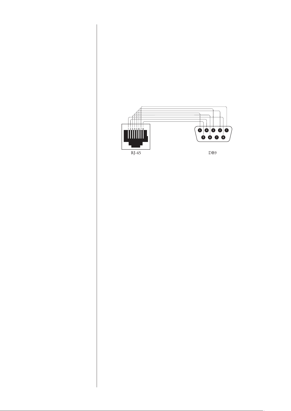
RJ-45 - DB9 female adaptor
If your RS-232 control system uses a cable with a male DB9 connector,
you will need to buy or build an adaptor to convert the RJ-45 female to a
DB9 female. Standard RJ45-to-DB9 female connectors come with RJ-45
pins and connections as below. Wire the DB9 adaptor according to this
diagram and table.
13
RJ-45 DB9
Pin-1 = DSR Pin-1 = N/C
Pin-2 = DTR Pin-2 = RXD
Pin-3 = CTS Pin-3 = TXD
Pin-4 = GND Pin-4 = DTR
Pin-5 = RXD Pin-5 = GND
Pin-6 = TXD Pin-6 = DSR
Pin-7 = N/C Pin-7 = N/C
Pin-8 = Power Input Pin-8 = CTS
Pin-9 = Power Input
Remarks: e Cat 5 cable that plugs into this adaptor and then into the
rear panel RJ-45 port must use pin-to-pin wiring (pin one to pin one, two
to two and so on).
9 USB Port
e USB connector is used to host a USB stick for updating amplier
rmware, should that become necessary.
10 Ethernet Port
e Ethernet port allows control and update features when connected to a
local network. It supports DHCP (dynamic host conguration protocol)
which means that it will have an IP address automatically assigned.
If static IP addressing is required, it can be accomplished by creating a
reservation table (see your router’s settings page) based on the amplier’s
MAC address printed on its serial number label (back-panel).
To perform rmware updates via the Ethernet port a network connection,
web browser and the rmware le (*.bwu extension) is all that’s required.
In order to access the amplier’s web interface, the assigned IP address
needs to be entered in the browser’s address bar. Locate the IP address by
looking at the connected devices table in your router’s setup interface,
or by using a network scanner app from a mobile device on the same
network.
If a reservation for the amp has been assigned in the router’s settings, then
it will be the reserved IP address. Once the web page is loaded, please
follow the instructions shown in the “Firmware” tab.
14
11 AC Mains Input (AC IN)
An IEC standard power cord (supplied) is used with the Delta MONO.
Plug the cord into the IEC receptacle on the rear panel, and the other end
into a suitable wall outlet.
12 AC Mains Fuse
Your Classé power amplier has an AC mains fuse, accessible on the
rear panel. If you suspect that your AC fuse has blown, disconnect your
amplier from the AC mains, as well as from its input connections and
speaker connections, and refer to the appropriate item of the section
enitled Troubleshooting.
13 ICTunnel
™
Exhaust Port
e Intelligent Cooling Tunnel removes heat from the amplier via the
exhaust port on the rear. To ensure the proper operation of the cooling
system, be careful to keep the area around the rear of the amplier free of
obstructions. See also the section on Ventilation
Do not open your amplier. ere are no user-serviceable parts within
this product.
Danger! Potentially dangerous voltages and current capabilities exist
within your power amplifier, even when disconnected from AC
mains. Do not attempt to open any portion of the amplifier’s
cabinet. There are no user-serviceable parts inside your power
amplifier. All service of this product must be referred to a
qualified Classé dealer or distributor.

15
Installation
Your new Classé amplier is quite simple to set up and enjoy. Please follow the
steps outlined below in order to safely set up and use your new amplier.
Important:
It is always a good idea to power up your power amplifier(s)
last, after everything else has been powered up and has
stabilized. .
Conversely, it is good practice to power the amplifier(s)
down first when shutting down the system, as this
prevents any transients from other components from
getting through to your loudspeakers.
1. Unpack everything according to the included instructions.
Be careful when doing so, as this amplier is quite heavy.
2.
Place your amplifier (be sure to read “Unpacking and Placement”)
and connect it to the AC mains. is includes deciding on the location,
making sure you have adequate ventilation, and adequate clearance for all the wires
behind the amplier. Once accomplished, connect the amplier directly to the
AC mains. A high-performance power cord has been selected and supplied with
your amplier. Do not use extension cords, as most are not suitable for the current
sometimes required by your amplier.
3. Make your preamp/processor connections.
With the amplier in standby (or disconnected from the AC mains), using
high quality interconnecting cables, make the appropriate connections
with the balanced or single-ended connectors. Do NOT connect preamps/
processors to both balanced and single-ended inputs at the same time. is
could result in damage to the input circuitry which is not covered under
warranty.
Make sure all the connections are snug, even if it means gently squeezing
the outer shell of the RCA with pliers and reinserting it to tighten the
connection.
4. Make your speaker connections.
Make the connection between the output terminals of the amplier and
your loudspeakers, using high quality speaker wires.
Connect the black (–) terminals on the amplier to the black (–) terminals
on your speaker, and the red (+) terminals on the amplier to the red (+)
terminals on your speaker. If bi-wiring, run a total of four conductors
between each amplier channel and its corresponding loudspeaker: two
separate +/– leads, one for the bass and the other for the mids and treble.
Make sure that no wires cross between the red (+) and black (–) terminals,
at either end.

16
e Delta MONO utilizes premium quality binding posts that provide
an optimum torque feature which ensures the correct pressure or tightness
of the connection while preventing damage that can result from over-
tightening. Secure the speaker cables by tightening the binding posts until
you hear the clicks indicating you’ve reached the proper torque for the
connection.
5. Double-check all your connections.
We understand that this step sounds redundant, but it is worth the extra
minute or two it might take just to ensure that all connections are correct
and secure before plugging the power cables to the AC outlets.
6. Turn on all the other components in your system, and then
turn on your amplifier.
It is always good practice to turn any power amplier on last, and to turn
it o rst. Doing so prevents any turn-on/turn-o transients that might
originate in other components from damaging your loudspeakers.
Your amplier will reach thermal equilibrium in 10-15 minutes. is
eliminates the need to keep the amplier on for extended periods of time.
If you plan to not use it for a while, it is best to keep it in standby.

17
CAN-Bus
CAN-Bus Classé’s Controller Area Network, or CAN-Bus, allows communication and
control between similarly featured Classé
components. When the amplier
is connected with other CAN-Bus-equipped Class
é
components, the dierent
elements in the system are in constant communication, creating a “global”
network that delivers system wide status information and shared operational
features, all through the preamp/processor’s touchscreen display.
Note that some components will require a software update to recognize the
Delta MONO on the CAN-Bus. Check the Classé website periodically for
updates.
features CAN-Bus will allow a
Class
é touchscreen to:
• Display status information for every connected unit, including
ampliers which do not have a touchscreen display.
• Create a “PlayLink” that allows an SSP or Preamp to automatically
switch to the correct input when a Delta series source component
starts playback.
• Adjust the global system brightness.
• Congure the entire system to go in and out of standby at the touch of
a button and also bring individual components in and out of standby.
• Mute any connected unit.
hardware setup 1 Classé CAN-Bus Equipped Products
Two or more Classé CAN-Bus equipped products are required, at least one of
which must have a touchscreen display.
2 Category 5 Network Cables
ese are ordinary network cables, commonly used for broadband Internet
connections. ey should be typical “straight through” cables not the “crossed
over” type, and the total required will be one less than the total number of
CAN-Bus equipped components in your system. Daisy chain the components
from one to the next using these network cables.
3 CAN-Bus Terminator
A single CAN-Bus Terminator may be required. It is inserted into the
CAN-Bus OUT connector of the last component in the CAN-Bus daisy
chain. One is
included in the box with your amplier. T
hey are also available
for a small fee from your nearest Classé Customer Support Centre.
https://classeaudio.com/contact/

18
using CAN-Bus CAN-Bus is controlled via the touchscreen of any
Classé
component that is
so equipped. ere is no master component, so
Classé
series systems where
two or more units have a touchscreen can be controlled through any of the
touchscreens. However, it is probably easiest to start using CAN-Bus through
just one.
CAN-Bus is accessed by pressing the menu button on the face of the unit or
remote, then the status button, followed by the more button (right arrow)
in the upper right corner of the screen. e touchscreen will then display the
CAN-Bus devices screen, which lists connected components by model & serial
number.
Selecting a unit on the CAN-Bus devices screen identies it as the target unit.
e front panel LED(s) or meter light of the target unit will start ashing (unless
you choose the unit that you are using to access CAN-Bus).
Once you have chosen the target unit, the touch screen will list the CAN-Bus
features available to it. Some CAN-Bus features are shared by all models, some
are specic to individual models.
Make sure to exit the CAN-Bus pages before putting your unit(s) into
Standby, otherwise the previously selected unit will continue to ash its
front panel LED when powering up the next time.
CAN-Bus amp features e following CAN-Bus features are available on the Delta MONO.
e model, name and rmware version number will be displayed on the
CAN-Bus page of the targeted unit.
Operate e Operate button allows you to bring the target unit in and out of standby.
is button will be disabled for the unit whose touchscreen you are using to
access CAN-Bus.
Mute Engaging Mute will mute the output of the target unit.

19
Global Standby By setting all your components to Global Standby you can bring your entire
system in and out of standby by pressing the standby button of any unit or
remote. All CAN-Bus software updates automatically set the updated unit
to Global Standby. If you want a particular unit to be excluded from Global
Standby, deselect Global Standby for that unit.
Global Dim By setting all your components to Global Dim (referred to as Global Brightness
in earlier models), you can adjust the touchscreen and LED brightness for your
entire system by changing the brightness of a single touchscreen. All CAN-Bus
software updates automatically set the updated unit to Global Dim. If you want
a particular unit to be excluded from Global Dim, deselect Global Dim for that
unit.
Other status e Other Status screen displays information about the target unit’s internal
temperature sensors. Readings for Heatsink 1 & 2 are displayed in degrees
Celsius.
Note: is feature is only available when the target amplier is in operate mode.
name You can set the name which will appear next to the unit model name and
facilitate the identication of units in large systems.
Event Log Reserved for ampliers, this feature records protection circuit events and can
only be accessed when the target amplier is in standby.
Note: For the amp to be put into standby while allowing the unit with the
touchscreen to remain in operate mode, Global Standby for the amp must be de-
selected (not highlighted) so the amp can be manually put into standby.
e protection circuit shuts down the amplier or channel if it overheats or if
its output could damage your speakers. e Event Log details the circumstances
surrounding the amp going into protection and should be referred to in
situations that require the intervention of your dealer or Classé customer
support.
e Delta MONO Event Log can report the following events interpreted as
follows:
• DC Output — DC from the source has exceeded the amplier’s
ability to correct for it. e amplier will shut down to protect the
loudspeaker.
• Over Current — e peak current has exceeded the safe operating
limit, i.e. a short circuit.
• CBE — Comm Board Error. ere has been an internal
communication error.
• Over Temp — e internal temperature has exceeded the safe
operating limit.
• Fan Failure — e fan has been disconnected or is unable to spin.
Protection events are rare and generally occur due to issues that are external
to the amp. ey should be interpreted positively. e amp is doing what it’s
designed to do.
20
Care and Maintenance
To remove dust from the cabinet of your amplier, use a feather duster or a
lint-free soft cloth. To remove dirt and ngerprints, we recommend using a
microbre cloth and static free lens cleaner such as you would use for cleaning a
at panel display.
Special care should be taken to gently clean the meter lens to avoid marking it in
any way.
Caution! DO NOT use paper towels as they may scratch the meter
lens surface.
Caution! At no time should liquid cleaners be applied directly to
the amplifier, as direct application of liquids may result
in damage to electronic components within the unit.

21
Troubleshooting
In general, you should refer any service problems to your Classé dealer. Before
contacting your dealer, however, check to see if the problem is listed here.
1. No sound, and Standby LED is not lit.
• e amplier is not plugged into the AC mains, or the AC mains
are down (circuit breaker, fuse).
• A brown-out or short-term loss of power might require the
internal microprocessor to be reset. Unplug the unit for at least
30 seconds and then plug it in again and try powering it up.
• e AC mains fuse is blown. See Troubleshooting #4, below (or
contact your Classé dealer).
• e AC mains is out of range. Check the line voltage supplying
the amplier.
2. No sound, and Standby LED is blinking red.
• e protection circuitry has been engaged.
• Press and hold the standby button to reset the amplier.
• If the amplier does not reset or continues to go into protection
mode, disconnect the amplier from the AC mains, and
disconnect all inputs and outputs.
• Try to power up the amplier again, connecting it only to AC
power. If the LED continues to blink, there is a fault condition
in the amplier itself and it should be disconnected and taken to
your Classé dealer for service.
• If it powers up without any diculty, rst power it back down
and reconnect only the inputs, then restart the amplier. If
it again powers up normally, there may be a problem such as
shorted speaker leads. Check the connections to conrm there
are no obvious shorts, then connect rst one channel, followed
by the other, to conrm either that there is no longer a shorted
lead or if there is, which channel is shorted.
3. The amplifier keeps shutting off.
• If the shut down occurs after approximately 20 minutes being
idle, it is likely that the Auto Standby power saving feature
is enabled. With very low signal levels the amplier may not
reliably detect them, allowing Auto Standby to engage. To
determine its state or disable Auto Standby, see the Auto Standby
section of this manual.
• Make sure you are providing adequate ventilation to the
amplier and that the ambient room temperature is below 105°F
(40°C).
• Run through the troubleshooting sequence outlined above
(assuming the amplier is going into its protection mode).
• e amplier logs all protection circuit events--these are viewable
on the touchscreen of a CAN-Bus connected Classé component
or by your dealer on a PC using a special diagnostic program.
Contact your dealer to assess the likely cause of the trouble.

22
4. The AC mains fuse is blown.
ere is a specic troubleshooting procedure for a blown AC mains fuse,
since this rare occurrence sometimes indicates a signicant problem. Please
use the following steps, in order:
a. Disconnect your amplier from the AC mains, as well as from its
input connections and speaker connections, and remove the fuse
cover on the rear of the unit.
b. Check the fuse for continuity using an ohm meter, where the
resistance should be essentially zero ohms. If the fuse is “open”
or blown, replace it only with a fuse of the same type and rating
(specied below). Using any other type of fuse, particularly a larger-
value fuse, can result in permanent damage to your amplier. If
you are not comfortable replacing the fuse yourself, contact your
Classé dealer for assistance.
Mains voltage: 100-120VAC
Fuse type:
IEC time lag, high breaking capacity
Rating: 6.3AH 250V
Mains voltage: 200-240VAC
Fuse type:
IEC time lag, high breaking capacity
Rating: 3.15AH 250V
c. After replacing the fuse and fuse cover, reconnect the amplier to
the AC mains only and turn it on without reconnecting either the
inputs or the speaker wires. If the fuse blows again, disconnect it
from the AC mains and contact your Classé dealer for assistance.
d. If everything seems ne, place the amplier back into standby
and carefully reconnect the input cable and power up the
amplier. If the fuse then blows (or the amplier goes into
protection), you may have a serious fault with your preamplier/
processor. Contact your Classé dealer.
e. Finally, if everything is still ne, place the amplier in standby
and carefully reconnect the speaker wires. Check both ends of
the speaker wires for possible short circuits. en power up the
amplier again. If the amplier remains functional (the fuse
does not blow), then the original fuse probably blew in order to
protect the amplier from a large AC mains surge. If it blows
again, contact your Classé dealer for assistance.
6. The Standby LED is solid red and the VU Meter LED shows a
pulsing light pattern (heartbeat).
is is a normal reaction when the AC mains is abruptly interrupted or
turned o, instead of using the normal Standby procedure. e pulsing
LED shows a calibration period that lasts for 30 seconds after the AC
Mains has been re-established.

23
Specifications
n Frequency Response 1Hz – 650kHz, -3dB
(50Ω Source Impedance)
n Continuous Output power
(
Pure Class-A Operation)
35W / 8Ω
(at 1kHz, 0.1% THD+N) 300W / 8Ω
600W
/ 4Ω
(
With AC Line held constant)
1000W / 2Ω
n Harmonic Distortion
(500 kHz Bandwidth) <0.0016% at 1kHz
(500kHz/25Vrms in 4Ω or 8Ω) <0.0018% at 10kHz
<0.0028% at 20kHz
n Harmonic Distortion
(90 kHz Bandwidth) <0.0005% at 1kHz
(90kHz/25Vrms in 4Ω or 8Ω) <0.0006% at 10kHz
<0.0015% at 20kHz
n Peak Output Voltage
(No Load) 148V peak-to-peak, 40Vrms
(Nominal AC Line) (8Ω Load)
113V peak-to-peak, 40Vrms
n Input Impedance
(Balanced/Single-Ended) 82kΩ
n Voltage Gain
(at 1kHz, Balanced/Single-Ended) 29dB
n Input Level for Nominal Output
(Balanced/Single-Ended) 1.74Vrms
n Intermodulation Distortion SMPTE 4:1 <0.001%
(4Ω or 8Ω, Bal/SE) CCIF <0.002%
n Signal-to-Noise Ratio 117dB
(22kHz Bandwidth, 1.84Vrms input) (A-Weighted) 119.5dB
n Slew Rate 72V/µs
n Output Impedance 0.010
Ω / 0.011Ω / 0.015Ω
(100 Hz / 1 kHz / 10 kHz)
n Damping Factor (at 1kHz, ref 8Ω Load) 700
n Standby Power Consumption
(for North American 120V) (Wake on Network disabled*) 0.22W
(Wake on Network enabled) 2.8W
(for Europe 230V) (Wake on Network disabled*) 0.4W
(Wake on Network enabled) 2.8W
(*20 mins after AC is applied)
n Power Consumption
(for North American 120V) Rated (1/8
th
into 4Ω) 5.4 A / 610VA (407W)
Max. Power (300W into 8Ω) 715VA (500W)
(for Europe 230V) Rated (1/8
th
into 4Ω) 3.0 A / 565VA (398W)
Max. Power (300W into 8Ω) 715VA (500W)

24
n Power Supply
100V~ 50/60Hz
(e MONO is congured to one of these AC congurations) 120V~ 50/60Hz
230V~ 50/60Hz
Note: Refer to the rear panel of the MONO for the congured voltage
n Operating Temperature 50-95 ° F (10-35 ° C)
n Overall Dimensions
(17.50”) 444mm Width
(incl. connectors) (19.37”) 492mm Depth
(incl. feet) (8.74”) 222mm Height
n Net Weight (97.7lbs) 44.3kg
n Shipping Weight (111.6lbs) 50.6kg
All Tests performed unweighted using balanced inputs and 500kHz measurement bandwidth (except when specied
otherwise). For purposes of improvement, specications and design are subject to change without notice.
For more information, see your Classé dealer, or contact our Headquarters at:
Sound United, LLC
One Viper Way
Vista, CA 92081
United States
Internet: https://classeaudio.com
Classé and the Classé logo are trademarks of Sound United, LLC. All rights reserved.
AMX® is a registered trademark of AMX Corporation of Richardson, TX. All rights reserved.
Crestron™ is a trademark of Crestron Electronics, Inc. of Rockleigh, NJ. All rights reserved.
Control 4™ is a trademark of Control 4 Corporation of Saltlake City UT. All rights reserved.
25
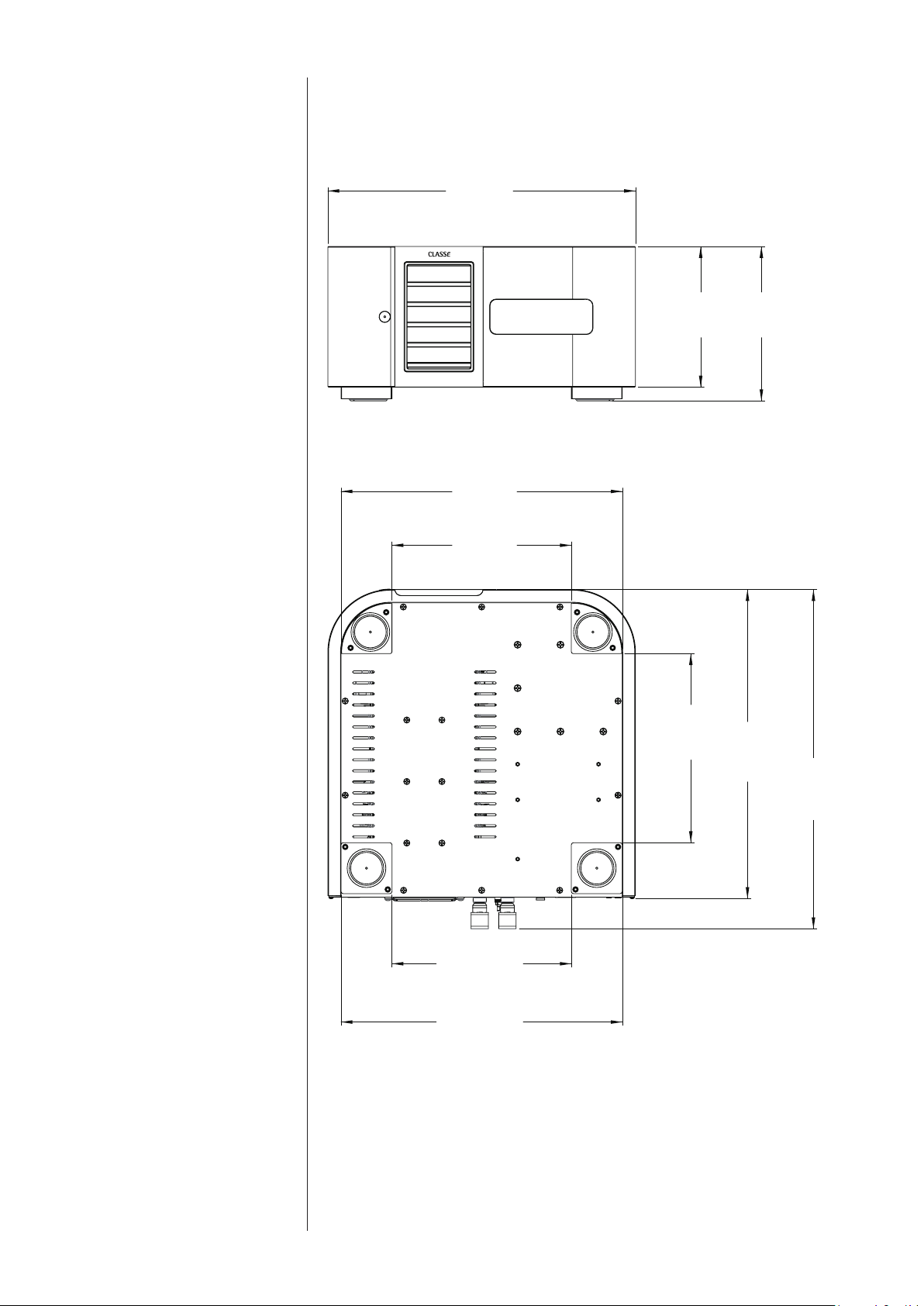
Dimensions
Delta MONO
17.50in
[ 445mm ]
8.00in
[ 203mm ]
8.78in
[ 223mm ]
10.21in
[ 259mm ]
16.00in
[ 406mm ]
17.58in
[ 447mm ]
10.76in
[ 273mm ]
19.31in
[ 490mm ]
10.20in
[ 259mm ]
16.00in
[ 406mm ]
Delta MONO