Loading ...
out of range, and the date and time the channel reading
returned to within range.
VIEWING THE MEMORY CAPACITY
Slide the MEM VIEW switch to the ON position.
First line will display the current percentage of memory
full. Second line will display the number of days remaining
before memory is full at the current logging interval. Third
line will display the current logging interval.
CLEARING THE MEMORY
1. Slide the MEM VIEW switch to the ON position.
2. Press the CLEAR SILENCE ALM button to clear all
recorded data and alarm events.
Note: The MEM symbol will become active on the display
when the memory is full. Once the memory is full, the
oldest data points will be overwritten with new data.
SETTING THE LOGGING INTERVAL
1. Slide the MEM VIEW switch to the ON position. The
rst line will display the current percentage of memory
full. The second line will display the number of days
remaining before memory is full at the current logging
interval. The third line will display the current logging
interval.
2. To increment the logging interval, press the ADVANCE
button. The minimum logging interval is one minute
(0:01). The maximum logging rate is 24 hours (24:00).
Once 24 hours is selected, the next subsequent press
of the ADVANCE button will return to one minute.
VIEWING UNIQUE DEVICE ID NUMBER
1. Slide the MEM VIEW switch to the ON position.
2. Press the EVENT DISPLAY button. The second and
third lines will display the rst eight digits of the ID
number.
3. Press the EVENT DISPLAY button a second time. The
second and third lines will display the last eight digits
of the ID number.
4. Press the EVENT DISPLAY button to return to the
default display.
DOWNLOADING STORED DATA
Note: The USB download will not occur if the battery
LCD symbol is active. Plug the supplied AC adapter
into the thermometer to provide sufcient power for USB
operation.
1. The data can be downloaded directly to a USB Mass
Storage Flash Drive. To begin download, insert
USB ash drive into USB port located on left side of
thermometer.
2. The download will begin upon insert. “MEM” will ap-
pear on display to indicate download has begun. Wait
up to 60 seconds for MEM symbol to appear after in-
sertion of ash drive. Flash drives with larger amounts
of data stored on the drive prior to downloading will
take longer to begin the download.
3. Once download process is complete, “MEM” will
disappear from display and a short beep will sound. Do
not remove USB drive until process is complete.
4. The data transfer rate is approximately 55 data points
per second.
Note: DO NOT leave USB Mass Storage Flash Drive
inserted into unit. Insert, DOWNLOAD, and then remove.
The device cannot continuously write to a USB.
REVIEWING STORED DATA
The downloaded data is stored in a comma-delimited
CSV le on ash drive. The lename naming convention
is “D1D2D3D4D5D6D7R1.CSV” where D1 through D7 are
the last seven digits of the thermometer’s unique ID num-
ber and R1 is the revision of le starting with letter “A”.
If more than one le is written from the same thermometer
to USB ash drive, revision letter will be incremented in
order to preserve previously downloaded les.
The data le can be opened in any software package
supporting comma-delimited les including spreadsheet
software (Excel) and text editors.
The le will contain the thermometer unique ID number,
the most recent ten temperature events, and all stored
temperature readings with date and time stamps.
Note: All data stored in Celsius (°C) and date format is
MM/DD/YYYY.
DISPLAY MESSAGES
If no buttons are pressed and LL.LL appears on the dis-
play, this indicates that the temperature being measured
is outside of the temperature range of the unit, or that the
probe is disconnected or damaged.
BENCH STAND
The unit is supplied with a bench stand located on the
back. To use the bench stand, locate the small opening at
the bottom back of the unit. Place your ngernail into the
opening and ip the stand out. To close the stand, simply
snap it shut.
BATTERY REPLACEMENT
To replace the battery, remove the battery cover, located
on the back of the unit by sliding it down. Remove the
exhausted batteries and replace with two (2) new AAA
alkaline batteries. Insert the new batteries with the proper
polarity as indicated by the illustration in the battery
compartment. Replace the battery cover.
Replacing the batteries WILL clear the minimum/maxi-
mum memories and high/low alarm settings. However,
replacing the batteries WILL NOT clear the time-of- day/
date settings or stored temperature data
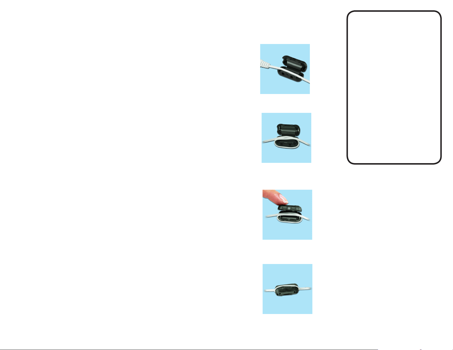
STATIC SUPPRESSOR INSTALLATION
Static generated, radio frequency can affect any cable
through the air or by physical contact. To protect against
radio frequency, install a suppressor onto your ther-
mometers cable to absorb radio frequency as follows:
TRACEABLE
EXCURSION-TRAC
DATALOGGING
THERMOMETER
INSTRUCTIONS
®
™
Lay the cable along the center of the
suppressor with the connector to your left.
Carefully, snap the two halves together with the looped
cable routed through the center.
Loop the right end of the cable under the
suppressor and back up again laying the cable along
the center of the suppressor.
This completes the installation of the suppressor.
Cat. No. 6430 / 6431 / 6432 / 6433 / 6434 / 6435 / 6436 / 6437 /
6438 / 6450 / 6451
©2017 92-6430-40 Rev. 6 11017