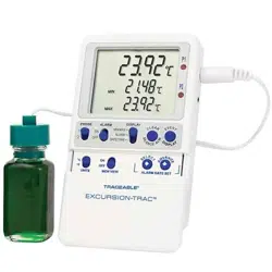
SPECIFICATIONS
Range: –50.00 to 70.00°C
Accuracy: ±0.25°C
Resolution: 0.01°
Temperature
Sampling Rate: 5 seconds
Memory Capacity: 525,600 points
USB Download Rate: 55 readings per second
Battery: 2 AAA (1.5V)
Probe labeled P1 must be plugged into the probe jack
labeled “P1” and probe labeled P2 must be plugged into
the probe jack labeled “P2”.
NOTE: All serial numbers (s/n#) must match between
probe and unit.
PROBES SUPPLIED: Model 6430 / 6431-- 1 bottle probe
(6430) or 2 bottle probes (6431), designed for use in refrigera-
tors/freezers. Bottle probes are lled with a patented nontoxic
glycol solution that is GRAS (Generally Recognized As Safe)
by the FDA (Food and Drug Administration) eliminating con-
cerns about incidental contact with food or drinking water.
Solution lled bottles simulate temperatures of other stored
liquids. Velcro
®
and a magnetic strip are provided to mount
the bottle inside a refrigerator/freezer. Included micro-thin
probe cable permits refrigerator/freezer doors to close on it.
(Do not immerse bottle probes in liquid).
Model 6432 / 6433-- standard plastic probe with cable.
Designed for use in air and liquids, sensor and cable may be
completely immersed.
Model 6434– 1 bottle probe with cable and 1 standard plastic
probe with cable.
Model 6435 / 6436– 1 stainless-steel probe (6435) or 2
stainless-steel probes (6436) triple-purpose probe for liquids,
air/gas, and semisolids. Accurate readings with tip penetration
of
1
/
3
-inch. Probe has a diameter of ⅛-inch, stem length of 6¼
inch, overall length of 9 inch and 10 ft cable.
Model 6437 / 6438-- 5ml bottle probe with cable. (0.6” x 2”)
Designed for use in vaccine storage.
Model 6450 / 6451-- plastic bottle probe with cable. Bottle
probes are lled with a patented nontoxic glycol solution
that is GRAS (Generally Recognized As Safe) by the FDA
(Food and Drug Administration) eliminating concerns about
incidental contact with food or drinking water.
(Do not immerse bottle probes in liquid).
SETTING THE TIME-OF-DAY/DATE
1. Slide the DISPLAY switch to the DATE/TIME position,
the thermometer will display the time-of-day and date.
Adjustable parameters are Year->Month->Day->Hour-
>Minute->12/24 hour time.
2. Press the SELECT button to enter the setting mode.
3. Subsequently press the SELECT button to select
which parameter to adjust. The selected parameter will
ash once selected.
4. Press the ADVANCE button to increment the selected
parameter.
5. Hold the ADVANCE button to continuously “roll” the
selected parameter.
6. Press EVENT DISPLAY button to toggle between
Month/Day (M/D) and Day/Month (D/M) modes.
If no button is pressed for 15 seconds while in the setting
mode, the thermometer will exit the setting mode.
Changing the position of the DISPLAY switch while in the
setting mode will save the current settings.
VIEWING THE TIME-OF-DAY/DATE
To view the time-of-day/date, slide the DISPLAY switch to
the DATE/TIME position.
SELECTING THE UNIT OF MEASURE
To select the desired unit of temperature measure (°C or
°F), slide the UNITS switch to the corresponding position.
SELECTING THE TEMPERATURE PROBE CHANNEL
Slide the PROBE switch to either position ‘1’ or position ‘2’
to select the corresponding probe channel P1 or P2.
All temperature readings displayed will correspond with
the selected probe channel.
Note: Both probe channels are sampled and monitored
continuously regardless of the selected probe channel.
MINIMUM AND MAXIMUM MEMORY
The minimum temperature stored in memory is the
minimum temperature measured since the last clear of
min/max memory. The maximum temperature stored in
memory is the maximum temperature measured since the
last clear of min/max memory.
MINIMUM AND MAXIMUM TEMPERATURE
VALUES ARE NOT PROGRAMMABLE.
Minimum and maximum temperature values are stored
individually for each probe channel P1 and P2. Both
channels are monitored continuously regardless of the
selected probe channel.
VIEWING MIN/MAX MEMORY
1. Slide the PROBE switch to select temperature probe
channel to be displayed.
2. Slide the DISPLAY switch to the MIN/MAX position.
3. The thermometer will display the current, minimum,
and maximum temperatures for the selected probe
channel.
4. Press the EVENT DISPLAY button to display the
minimum temperature with the corresponding date and
time of occurrence.
5. Press the EVENT DISPLAY button a second time to
display the maximum temperature with the corre-
sponding date and time of occurrence.
6. Press the EVENT DISPLAY button to return to the
current temperature display.
No button press for 15 seconds while viewing the mini-
mum or maximum event data will trigger the thermometer
to return to the current temperature display.
CLEARING THE MIN/MAX MEMORY
1. Slide the PROBE switch to select the temperature
probe channel to be cleared.
2. Slide the DISPLAY switch to the MIN/MAX position.
3. Press the CLEAR SILENCE ALM button to clear the
current minimum and maximum temperature readings.
Alarms
Alarm high and low limits can be set individually for each
probe channel (P1 and P2).
SETTING ALARM LIMITS
1. Slide the switch to the ALARM position. Then slide the
PROBE switch to select the probe channel for which
alarms will be set.
Each digit of the alarm value is set individually:
Low Alarm Sign (Positive/Negative) -> Low Alarm
Hundreds/Tens -> Low Alarm Ones -> Low Alarm Tenths
-> High Alarm Sign (Positive/Negative) -> High Alarm
Hundreds/Tens -> High Alarm Ones -> High Alarm Tenths.
2. Press the SELECT button to enter the setting mode.
The LOW ALM symbol will ash.
3. Press the SELECT button to select the digit to adjust.
Each subsequent press of the SELECT button will
move to the next digit. The digit will ash while
selected.
4. Press ADVANCE button to increment selected digit.
Note: The negative sign will ash if the sign is negative;
no symbol will ash if the sign is positive. Press the
ADVANCE button to toggle the sign while it is selected.
If no button is pressed for 15 seconds while in the setting
mode, the thermometer will exit the setting mode.
Changing the position of the DISPLAY switch while in the
setting mode will save the current settings.
VIEWING THE ALARM LIMITS
1. Slide the PROBE switch to select the probe channel
alarm limits to be displayed.
2. Slide the DISPLAY switch to the ALARM position.
ENABLING/DISABLING ALARMS
1. Slide the ALARM switch to the ON or OFF position to
enable or disable the alarms.
2. Alarms are enabled for both probe channels P1 and
P2 while the switch is set to ON. Alarms are disabled
for both probe channels P1 and P2 while the switch is
set to OFF.
3. The alarms cannot be congured to enable individual
channels P1 or P2 only.
ALARM EVENT HANDLING
An alarm event will trigger if the alarm is enabled and a
temperature reading is recorded below the low alarm set
point or above the high alarm set point.
When an alarm event triggers, the thermometer buzzer
will sound, and the LED for the alarming temperature
channel will ash (P1 or P2). If the alarming probe chan-
nel is selected, the LCD symbol will ash signaling which
set point was breached (HI ALM or LO ALM).
An active alarm may be cleared by either pressing the
CLEAR SILENCE ALM button or disabling the alarm func-
tionality by sliding the ALARM switch to the OFF position.
Once an alarm is cleared, it will not re-trigger until after
the temperature returns to within the alarm limits.
Note: If an alarm event is triggered and returns to within
the alarm limits before being cleared, the alarm event will
remain active until it is cleared.
VIEWING ALARM EVENT MEMORY
1. Slide the PROBE switch to select the probe channel
alarm data to be displayed.
2. Slide the DISPLAY switch to the ALARM position. The
current temperature, low alarm limit, and high alarm
limit will display.
3. Press the EVENT DISPLAY button. The thermometer
will display the alarm limit, date, and time of the most
recent alarm out of range condition. The symbol ALM
OUT will display to signal the date and time displayed
indicate when the temperature when out of tolerance.
4. Press the EVENT DISPLAY button a second time.
The thermometer will display the alarm limit, date, and
time of the most recent alarm event returning to within
the alarm limits. The symbol ALM IN will display to
signal the date and time displayed indicate when the
temperature returned to within tolerance.
5. Press the EVENT DISPLAY button to return to the
current temperature display.
No button press for 15 seconds while viewing the alarm
events will trigger the thermometer to return to the current
temperature display.
Note: If no alarm event has occurred for the selected
probe channel, the thermometer will display “LLL.LL” on
each line.
DATA LOGGING OPERATION
Thermometer will continuously log temperature readings
for both probe channels into permanent memory at
user-specied intervals. The total memory capacity
is 525,600 data points. Each data point contains the
temperature reading for P1, the temperature reading for
P2, and the date and time of occurrence.
Note: All data stored in Celsius (°C) and date format is
MM/DD/YYYY.
Note: DO NOT leave the USB Mass Storage Flash
Drive inserted into the unit. Insert, DOWNLOAD, and
then remove. The device cannot continuously write
to a USB.
The thermometer will also store the most recent 10 alarm
events. Each alarm event data point contains the probe
channel which alarmed, the alarm set point that was
triggered, the date and time the channel reading went
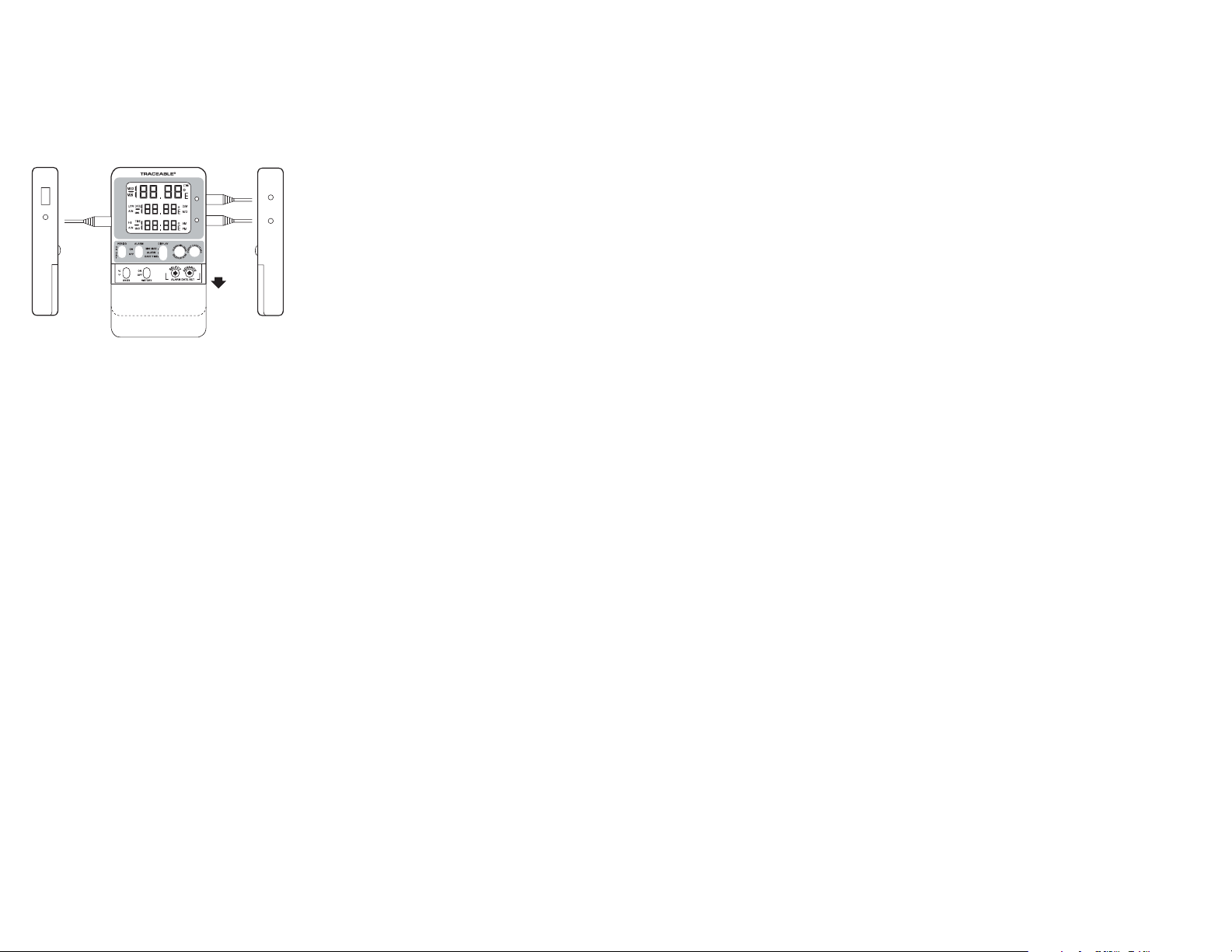
AC Adaptor
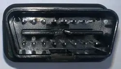
Jack
Supplied
Probe
Right SideLeft Side
P2
P1
P1
Probe
Jack
P2
Probe
Jack
AC
Adaptor
Jack
SLIDE
DOWN
USB
SPECIFICATIONS
Range: –50.00 to 70.00°C
Accuracy: ±0.25°C
Resolution: 0.01°
Temperature
Sampling Rate: 5 seconds
Memory Capacity: 525,600 points
USB Download Rate: 55 readings per second
Battery: 2 AAA (1.5V)
Probe labeled P1 must be plugged into the probe jack
labeled “P1” and probe labeled P2 must be plugged into
the probe jack labeled “P2”.
NOTE: All serial numbers (s/n#) must match between
probe and unit.
PROBES SUPPLIED: Model 6430 / 6431-- 1 bottle probe
(6430) or 2 bottle probes (6431), designed for use in refrigera-
tors/freezers. Bottle probes are lled with a patented nontoxic
glycol solution that is GRAS (Generally Recognized As Safe)
by the FDA (Food and Drug Administration) eliminating con-
cerns about incidental contact with food or drinking water.
Solution lled bottles simulate temperatures of other stored
liquids. Velcro
®
and a magnetic strip are provided to mount
the bottle inside a refrigerator/freezer. Included micro-thin
probe cable permits refrigerator/freezer doors to close on it.
(Do not immerse bottle probes in liquid).
Model 6432 / 6433-- standard plastic probe with cable.
Designed for use in air and liquids, sensor and cable may be
completely immersed.
Model 6434– 1 bottle probe with cable and 1 standard plastic
probe with cable.
Model 6435 / 6436– 1 stainless-steel probe (6435) or 2
stainless-steel probes (6436) triple-purpose probe for liquids,
air/gas, and semisolids. Accurate readings with tip penetration
of
1
/
3
-inch. Probe has a diameter of ⅛-inch, stem length of 6¼
inch, overall length of 9 inch and 10 ft cable.
Model 6437 / 6438-- 5ml bottle probe with cable. (0.6” x 2”)
Designed for use in vaccine storage.
Model 6450 / 6451-- plastic bottle probe with cable. Bottle
probes are lled with a patented nontoxic glycol solution
that is GRAS (Generally Recognized As Safe) by the FDA
(Food and Drug Administration) eliminating concerns about
incidental contact with food or drinking water.
(Do not immerse bottle probes in liquid).
SETTING THE TIME-OF-DAY/DATE
1. Slide the DISPLAY switch to the DATE/TIME position,
the thermometer will display the time-of-day and date.
Adjustable parameters are Year->Month->Day->Hour-
>Minute->12/24 hour time.
2. Press the SELECT button to enter the setting mode.
3. Subsequently press the SELECT button to select
which parameter to adjust. The selected parameter will
ash once selected.
4. Press the ADVANCE button to increment the selected
parameter.
5. Hold the ADVANCE button to continuously “roll” the
selected parameter.
6. Press EVENT DISPLAY button to toggle between
Month/Day (M/D) and Day/Month (D/M) modes.
If no button is pressed for 15 seconds while in the setting
mode, the thermometer will exit the setting mode.
Changing the position of the DISPLAY switch while in the
setting mode will save the current settings.
VIEWING THE TIME-OF-DAY/DATE
To view the time-of-day/date, slide the DISPLAY switch to
the DATE/TIME position.
SELECTING THE UNIT OF MEASURE
To select the desired unit of temperature measure (°C or
°F), slide the UNITS switch to the corresponding position.
SELECTING THE TEMPERATURE PROBE CHANNEL
Slide the PROBE switch to either position ‘1’ or position ‘2’
to select the corresponding probe channel P1 or P2.
All temperature readings displayed will correspond with
the selected probe channel.
Note: Both probe channels are sampled and monitored
continuously regardless of the selected probe channel.
MINIMUM AND MAXIMUM MEMORY
The minimum temperature stored in memory is the
minimum temperature measured since the last clear of
min/max memory. The maximum temperature stored in
memory is the maximum temperature measured since the
last clear of min/max memory.
MINIMUM AND MAXIMUM TEMPERATURE
VALUES ARE NOT PROGRAMMABLE.
Minimum and maximum temperature values are stored
individually for each probe channel P1 and P2. Both
channels are monitored continuously regardless of the
selected probe channel.
VIEWING MIN/MAX MEMORY
1. Slide the PROBE switch to select temperature probe
channel to be displayed.
2. Slide the DISPLAY switch to the MIN/MAX position.
3. The thermometer will display the current, minimum,
and maximum temperatures for the selected probe
channel.
4. Press the EVENT DISPLAY button to display the
minimum temperature with the corresponding date and
time of occurrence.
5. Press the EVENT DISPLAY button a second time to
display the maximum temperature with the corre-
sponding date and time of occurrence.
6. Press the EVENT DISPLAY button to return to the
current temperature display.
No button press for 15 seconds while viewing the mini-
mum or maximum event data will trigger the thermometer
to return to the current temperature display.
CLEARING THE MIN/MAX MEMORY
1. Slide the PROBE switch to select the temperature
probe channel to be cleared.
2. Slide the DISPLAY switch to the MIN/MAX position.
3. Press the CLEAR SILENCE ALM button to clear the
current minimum and maximum temperature readings.
Alarms
Alarm high and low limits can be set individually for each
probe channel (P1 and P2).
SETTING ALARM LIMITS
1. Slide the switch to the ALARM position. Then slide the
PROBE switch to select the probe channel for which
alarms will be set.
Each digit of the alarm value is set individually:
Low Alarm Sign (Positive/Negative) -> Low Alarm
Hundreds/Tens -> Low Alarm Ones -> Low Alarm Tenths
-> High Alarm Sign (Positive/Negative) -> High Alarm
Hundreds/Tens -> High Alarm Ones -> High Alarm Tenths.
2. Press the SELECT button to enter the setting mode.
The LOW ALM symbol will ash.
3. Press the SELECT button to select the digit to adjust.
Each subsequent press of the SELECT button will
move to the next digit. The digit will ash while
selected.
4. Press ADVANCE button to increment selected digit.
Note: The negative sign will ash if the sign is negative;
no symbol will ash if the sign is positive. Press the
ADVANCE button to toggle the sign while it is selected.
If no button is pressed for 15 seconds while in the setting
mode, the thermometer will exit the setting mode.
Changing the position of the DISPLAY switch while in the
setting mode will save the current settings.
VIEWING THE ALARM LIMITS
1. Slide the PROBE switch to select the probe channel
alarm limits to be displayed.
2. Slide the DISPLAY switch to the ALARM position.
ENABLING/DISABLING ALARMS
1. Slide the ALARM switch to the ON or OFF position to
enable or disable the alarms.
2. Alarms are enabled for both probe channels P1 and
P2 while the switch is set to ON. Alarms are disabled
for both probe channels P1 and P2 while the switch is
set to OFF.
3. The alarms cannot be congured to enable individual
channels P1 or P2 only.
ALARM EVENT HANDLING
An alarm event will trigger if the alarm is enabled and a
temperature reading is recorded below the low alarm set
point or above the high alarm set point.
When an alarm event triggers, the thermometer buzzer
will sound, and the LED for the alarming temperature
channel will ash (P1 or P2). If the alarming probe chan-
nel is selected, the LCD symbol will ash signaling which
set point was breached (HI ALM or LO ALM).
An active alarm may be cleared by either pressing the
CLEAR SILENCE ALM button or disabling the alarm func-
tionality by sliding the ALARM switch to the OFF position.
Once an alarm is cleared, it will not re-trigger until after
the temperature returns to within the alarm limits.
Note: If an alarm event is triggered and returns to within
the alarm limits before being cleared, the alarm event will
remain active until it is cleared.
VIEWING ALARM EVENT MEMORY
1. Slide the PROBE switch to select the probe channel
alarm data to be displayed.
2. Slide the DISPLAY switch to the ALARM position. The
current temperature, low alarm limit, and high alarm
limit will display.
3. Press the EVENT DISPLAY button. The thermometer
will display the alarm limit, date, and time of the most
recent alarm out of range condition. The symbol ALM
OUT will display to signal the date and time displayed
indicate when the temperature when out of tolerance.
4. Press the EVENT DISPLAY button a second time.
The thermometer will display the alarm limit, date, and
time of the most recent alarm event returning to within
the alarm limits. The symbol ALM IN will display to
signal the date and time displayed indicate when the
temperature returned to within tolerance.
5. Press the EVENT DISPLAY button to return to the
current temperature display.
No button press for 15 seconds while viewing the alarm
events will trigger the thermometer to return to the current
temperature display.
Note: If no alarm event has occurred for the selected
probe channel, the thermometer will display “LLL.LL” on
each line.
DATA LOGGING OPERATION
Thermometer will continuously log temperature readings
for both probe channels into permanent memory at
user-specied intervals. The total memory capacity
is 525,600 data points. Each data point contains the
temperature reading for P1, the temperature reading for
P2, and the date and time of occurrence.
Note: All data stored in Celsius (°C) and date format is
MM/DD/YYYY.
Note: DO NOT leave the USB Mass Storage Flash
Drive inserted into the unit. Insert, DOWNLOAD, and
then remove. The device cannot continuously write
to a USB.
The thermometer will also store the most recent 10 alarm
events. Each alarm event data point contains the probe
channel which alarmed, the alarm set point that was
triggered, the date and time the channel reading went
AC Adaptor
Jack
Supplied
Probe
Right SideLeft Side
P2
P1
P1
Probe
Jack
P2
Probe
Jack
AC
Adaptor
Jack
SLIDE
DOWN
USB

out of range, and the date and time the channel reading
returned to within range.
VIEWING THE MEMORY CAPACITY
Slide the MEM VIEW switch to the ON position.
First line will display the current percentage of memory
full. Second line will display the number of days remaining
before memory is full at the current logging interval. Third
line will display the current logging interval.
CLEARING THE MEMORY
1. Slide the MEM VIEW switch to the ON position.
2. Press the CLEAR SILENCE ALM button to clear all
recorded data and alarm events.
Note: The MEM symbol will become active on the display
when the memory is full. Once the memory is full, the
oldest data points will be overwritten with new data.
SETTING THE LOGGING INTERVAL
1. Slide the MEM VIEW switch to the ON position. The
rst line will display the current percentage of memory
full. The second line will display the number of days
remaining before memory is full at the current logging
interval. The third line will display the current logging
interval.
2. To increment the logging interval, press the ADVANCE
button. The minimum logging interval is one minute
(0:01). The maximum logging rate is 24 hours (24:00).
Once 24 hours is selected, the next subsequent press
of the ADVANCE button will return to one minute.
VIEWING UNIQUE DEVICE ID NUMBER
1. Slide the MEM VIEW switch to the ON position.
2. Press the EVENT DISPLAY button. The second and
third lines will display the rst eight digits of the ID
number.
3. Press the EVENT DISPLAY button a second time. The
second and third lines will display the last eight digits
of the ID number.
4. Press the EVENT DISPLAY button to return to the
default display.
DOWNLOADING STORED DATA
Note: The USB download will not occur if the battery
LCD symbol is active. Plug the supplied AC adapter
into the thermometer to provide sufcient power for USB
operation.
1. The data can be downloaded directly to a USB Mass
Storage Flash Drive. To begin download, insert
USB ash drive into USB port located on left side of
thermometer.
2. The download will begin upon insert. “MEM” will ap-
pear on display to indicate download has begun. Wait
up to 60 seconds for MEM symbol to appear after in-
sertion of ash drive. Flash drives with larger amounts
of data stored on the drive prior to downloading will
take longer to begin the download.
3. Once download process is complete, “MEM” will
disappear from display and a short beep will sound. Do
not remove USB drive until process is complete.
4. The data transfer rate is approximately 55 data points
per second.
Note: DO NOT leave USB Mass Storage Flash Drive
inserted into unit. Insert, DOWNLOAD, and then remove.
The device cannot continuously write to a USB.
REVIEWING STORED DATA
The downloaded data is stored in a comma-delimited
CSV le on ash drive. The lename naming convention
is “D1D2D3D4D5D6D7R1.CSV” where D1 through D7 are
the last seven digits of the thermometer’s unique ID num-
ber and R1 is the revision of le starting with letter “A”.
If more than one le is written from the same thermometer
to USB ash drive, revision letter will be incremented in
order to preserve previously downloaded les.
The data le can be opened in any software package
supporting comma-delimited les including spreadsheet
software (Excel) and text editors.
The le will contain the thermometer unique ID number,
the most recent ten temperature events, and all stored
temperature readings with date and time stamps.
Note: All data stored in Celsius (°C) and date format is
MM/DD/YYYY.
DISPLAY MESSAGES
If no buttons are pressed and LL.LL appears on the dis-
play, this indicates that the temperature being measured
is outside of the temperature range of the unit, or that the
probe is disconnected or damaged.
BENCH STAND
The unit is supplied with a bench stand located on the
back. To use the bench stand, locate the small opening at
the bottom back of the unit. Place your ngernail into the
opening and ip the stand out. To close the stand, simply
snap it shut.
BATTERY REPLACEMENT
To replace the battery, remove the battery cover, located
on the back of the unit by sliding it down. Remove the
exhausted batteries and replace with two (2) new AAA
alkaline batteries. Insert the new batteries with the proper
polarity as indicated by the illustration in the battery
compartment. Replace the battery cover.
Replacing the batteries WILL clear the minimum/maxi-
mum memories and high/low alarm settings. However,
replacing the batteries WILL NOT clear the time-of- day/
date settings or stored temperature data
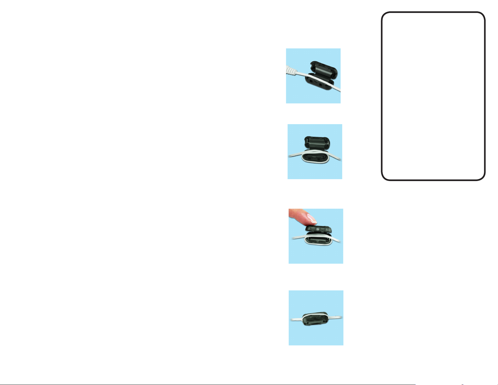
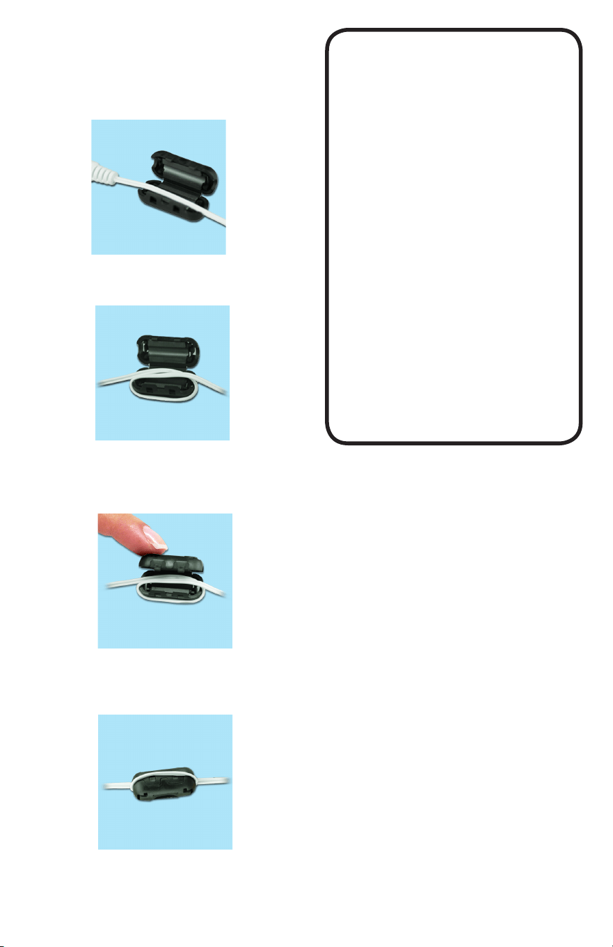
STATIC SUPPRESSOR INSTALLATION
Static generated, radio frequency can affect any cable
through the air or by physical contact. To protect against
radio frequency, install a suppressor onto your ther-
mometers cable to absorb radio frequency as follows:
TRACEABLE
EXCURSION-TRAC
DATALOGGING
THERMOMETER
INSTRUCTIONS
®
™
Lay the cable along the center of the
suppressor with the connector to your left.
Carefully, snap the two halves together with the looped
cable routed through the center.
Loop the right end of the cable under the
suppressor and back up again laying the cable along
the center of the suppressor.
This completes the installation of the suppressor.
Cat. No. 6430 / 6431 / 6432 / 6433 / 6434 / 6435 / 6436 / 6437 /
6438 / 6450 / 6451
©2017 92-6430-40 Rev. 6 11017
out of range, and the date and time the channel reading
returned to within range.
VIEWING THE MEMORY CAPACITY
Slide the MEM VIEW switch to the ON position.
First line will display the current percentage of memory
full. Second line will display the number of days remaining
before memory is full at the current logging interval. Third
line will display the current logging interval.
CLEARING THE MEMORY
1. Slide the MEM VIEW switch to the ON position.
2. Press the CLEAR SILENCE ALM button to clear all
recorded data and alarm events.
Note: The MEM symbol will become active on the display
when the memory is full. Once the memory is full, the
oldest data points will be overwritten with new data.
SETTING THE LOGGING INTERVAL
1. Slide the MEM VIEW switch to the ON position. The
rst line will display the current percentage of memory
full. The second line will display the number of days
remaining before memory is full at the current logging
interval. The third line will display the current logging
interval.
2. To increment the logging interval, press the ADVANCE
button. The minimum logging interval is one minute
(0:01). The maximum logging rate is 24 hours (24:00).
Once 24 hours is selected, the next subsequent press
of the ADVANCE button will return to one minute.
VIEWING UNIQUE DEVICE ID NUMBER
1. Slide the MEM VIEW switch to the ON position.
2. Press the EVENT DISPLAY button. The second and
third lines will display the rst eight digits of the ID
number.
3. Press the EVENT DISPLAY button a second time. The
second and third lines will display the last eight digits
of the ID number.
4. Press the EVENT DISPLAY button to return to the
default display.
DOWNLOADING STORED DATA
Note: The USB download will not occur if the battery
LCD symbol is active. Plug the supplied AC adapter
into the thermometer to provide sufcient power for USB
operation.
1. The data can be downloaded directly to a USB Mass
Storage Flash Drive. To begin download, insert
USB ash drive into USB port located on left side of
thermometer.
2. The download will begin upon insert. “MEM” will ap-
pear on display to indicate download has begun. Wait
up to 60 seconds for MEM symbol to appear after in-
sertion of ash drive. Flash drives with larger amounts
of data stored on the drive prior to downloading will
take longer to begin the download.
3. Once download process is complete, “MEM” will
disappear from display and a short beep will sound. Do
not remove USB drive until process is complete.
4. The data transfer rate is approximately 55 data points
per second.
Note: DO NOT leave USB Mass Storage Flash Drive
inserted into unit. Insert, DOWNLOAD, and then remove.
The device cannot continuously write to a USB.
REVIEWING STORED DATA
The downloaded data is stored in a comma-delimited
CSV le on ash drive. The lename naming convention
is “D1D2D3D4D5D6D7R1.CSV” where D1 through D7 are
the last seven digits of the thermometer’s unique ID num-
ber and R1 is the revision of le starting with letter “A”.
If more than one le is written from the same thermometer
to USB ash drive, revision letter will be incremented in
order to preserve previously downloaded les.
The data le can be opened in any software package
supporting comma-delimited les including spreadsheet
software (Excel) and text editors.
The le will contain the thermometer unique ID number,
the most recent ten temperature events, and all stored
temperature readings with date and time stamps.
Note: All data stored in Celsius (°C) and date format is
MM/DD/YYYY.
DISPLAY MESSAGES
If no buttons are pressed and LL.LL appears on the dis-
play, this indicates that the temperature being measured
is outside of the temperature range of the unit, or that the
probe is disconnected or damaged.
BENCH STAND
The unit is supplied with a bench stand located on the
back. To use the bench stand, locate the small opening at
the bottom back of the unit. Place your ngernail into the
opening and ip the stand out. To close the stand, simply
snap it shut.
BATTERY REPLACEMENT
To replace the battery, remove the battery cover, located
on the back of the unit by sliding it down. Remove the
exhausted batteries and replace with two (2) new AAA
alkaline batteries. Insert the new batteries with the proper
polarity as indicated by the illustration in the battery
compartment. Replace the battery cover.
Replacing the batteries WILL clear the minimum/maxi-
mum memories and high/low alarm settings. However,
replacing the batteries WILL NOT clear the time-of- day/
date settings or stored temperature data
STATIC SUPPRESSOR INSTALLATION
Static generated, radio frequency can affect any cable
through the air or by physical contact. To protect against
radio frequency, install a suppressor onto your ther-
mometers cable to absorb radio frequency as follows:
TRACEABLE
EXCURSION-TRAC
DATALOGGING
THERMOMETER
INSTRUCTIONS
®
™
Lay the cable along the center of the
suppressor with the connector to your left.
Carefully, snap the two halves together with the looped
cable routed through the center.
Loop the right end of the cable under the
suppressor and back up again laying the cable along
the center of the suppressor.
This completes the installation of the suppressor.
Cat. No. 6430 / 6431 / 6432 / 6433 / 6434 / 6435 / 6436 / 6437 /
6438 / 6450 / 6451
©2017 92-6430-40 Rev. 6 11017