Loading ...
Loading ...
Loading ...
Version 01/13- Page 8
WIRING DIAGRAM
DIAGRAMME DE CÂBLAGE
• This rangehood uses 20 watt Halogen Lamps. / Cette hotte utilise les ampoule halogènes de 20 W.
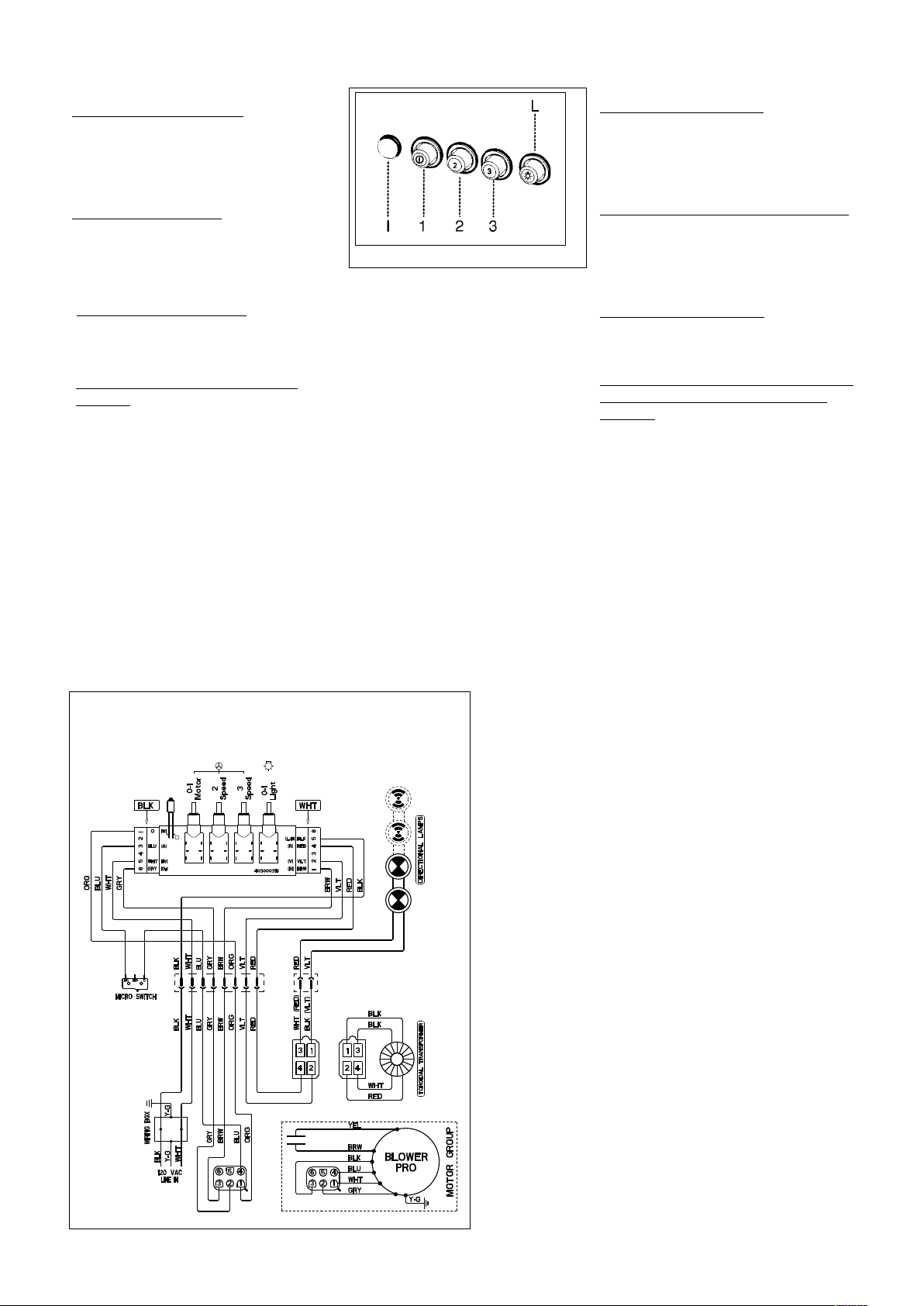
CONTROL PANELS AND WIRING DIAGRAMS
FIGURE 11 - 3-SPEED / 3 VITESSE
PANNEAU DE COMMANDES
Rangehood Control Panel
The control panel is located on the front
edge of the rangehood canopy. The
position and function of each control
button are indicated in FIGURE 11.
Light On/Off Button ( L )
On/Off switch for the halogen lights. Push
the button in to turn the light ON, push
again to turn the light OFF.
Blower Indicator Light ( I )
Lights up to indicate blower is ON.
Blower On/Off and Speed Buttons
( 1, 2, 3 )
Push button (1) to turn ON and OFF the
blower. This button must be pushed in
for the blower to operate regardless of
speed chosen. Button (1) operates the
blower on LOW speed. Push button (2)
for MEDIUM speed. Push button (3) for
HIGH speed.
Panneau de commandes
Le panneau de commandes est situé sur
le devant de la hotte. La position et la
fonction de chaque bouton sont indiquées
à la FIGURE 11.
Bouton marche-arrêt de la lumière (L)
Interrupteur marche-arrêt pour la lumière.
Pousser le bouton pour mettre en circuit
(ON), le pousser encore pour mettre hors
circuit (OFF).
Led allumage moteur ( I )
Illuminer pour indiquer la moteur en
circuit.
Bouton marche-arrêt du ventilateur et
Boutons de vitesse du ventilateur
( 1, 2, 3 )
Pousser le bouton (1) pour mettre en circuit
(ON), le pousser encore pour mettre hors
circuit (OFF). Régler à « 1 » pour vitesse
basse (LOW), à « 2 » pour vitesse moyenne
(MEDIUM) et à « 3 » pour vitesse élevée
(HIGH).
Loading ...
Loading ...
Loading ...