Loading ...
Loading ...
Loading ...
11
Installation
CONNECT ELECTRICAL
• Plug power cord into properly grounded
receptacle.
• Press the button on the left side of the control
panel. The lights above the knobs should
illuminate.
STEP 4
FINALIZE INSTALLATION
Place the burner grates over the burners. The
grates should be seated and should not rock.
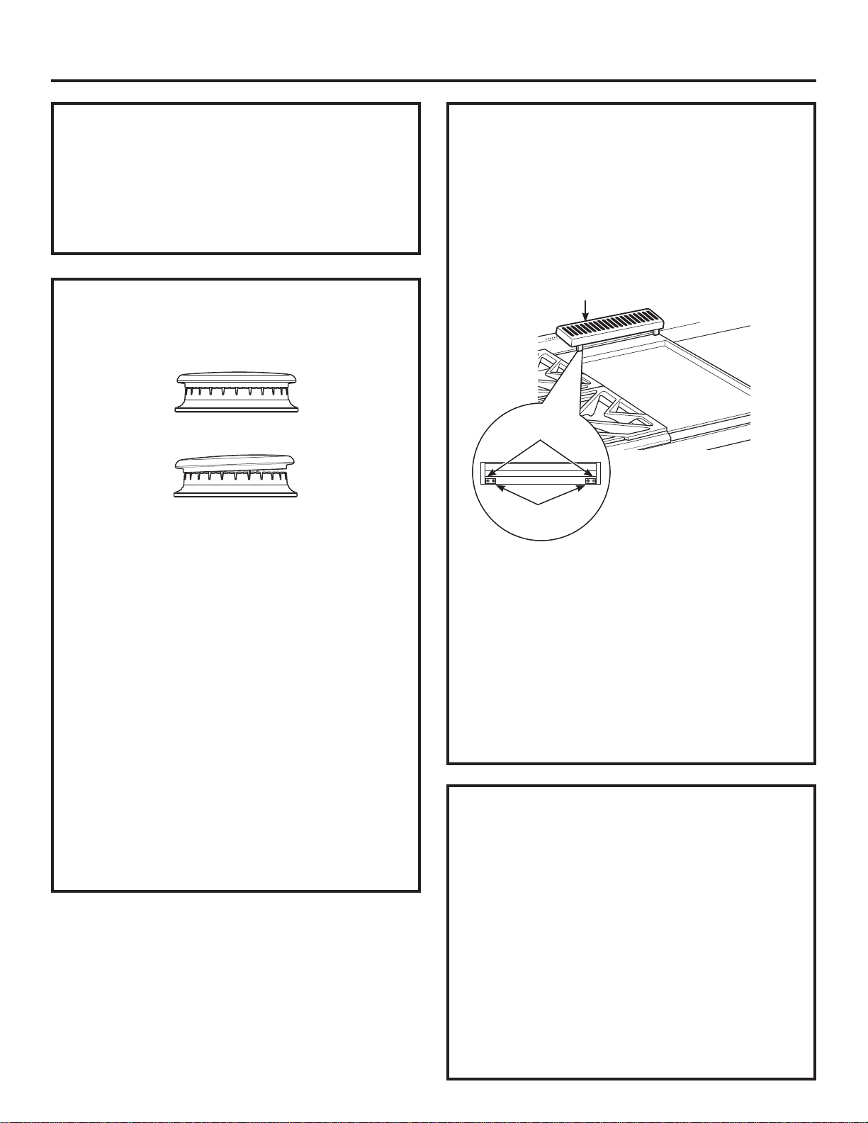
The griddle is secured with screws. It is designed to
be stationary and should not be removed.
The griddle has two leveling screws beneath the
rear flue cover that can be used to adjust to the
desired slope.
The two inner screws are clamping screws for
securing the griddle in place. Loosen these two
screws before leveling. Do not remove these two
screws.
The two outer screws are leveling screws. Do not
remove these two screws. They can be turned to
level the griddle or to provide a forward slope to
help grease and oils to drain away from the food
being cooked.
After leveling the griddle, hand-tighten the
clamping screws; do not over-tighten.
INSTALLATION CHECKLIST
■ Make sure all controls are left in the OFF
position.
■ Make sure the flow of combustion and
ventilation air to the rangetop is unobstructed.
■ The serial plate for your rangetop is located
on the bottom of the rangetop. In addition to
the model and serial numbers, it tells you the
ratings of the burners and the type of fuel and
pressure the rangetop was adjusted for when it
left the factory.
■ Recheck Steps:
Double check to make sure everything in this
manual has been completed. Rechecking steps
will ensure safe use of the rangetop.
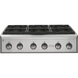
CHECK BURNERS
Check to be sure that burner heads and caps are
securely seated.
• Check for proper ignition:
– Push in one control knob and turn to LITE
position.
– The igniter will spark and the burner will light; the
igniter will cease sparking when the burner is lit.
– First test may require some time, while air is
flushed out of the gas line.
– Turn knob to OFF.
– Repeat the procedure for each burner.
IMPORTANT: If the igniter electrodes continue to
spark after the burners are lit, check that each
burner component is assembled properly. Refer to
the Owner’s Manual.
• Burner flames should be blue and stable with no
yellow tips, excessive noise or lifting of the flame
from the burner. If any of these conditions exist,
check that the burner ports are not blocked. If one
of these conditions continues, call for service.
STEP 5
Burner Cap Not Properly Seated
Burner Cap Properly Seated
Griddle Flue Cover
Clamping Screws
Leveling Screws
Loading ...
Loading ...
Loading ...