Installation Instructions for Digital Humidity Control
Duct Installation (recommended)
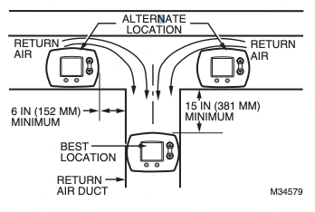
1. Choose a location on the RETURN duct.
Warning: Product must be mounted on the RETURN side of the duct for proper RH% sensing.
Remote Mount Installation
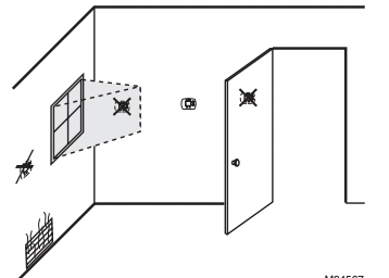
1. Choose a location in the living area.
NOTE: Select a location clear of drafts or excessive humidity. Avoid mounting near doors or windows, or in bathrooms or kitchens.
Duct-Mount Installation
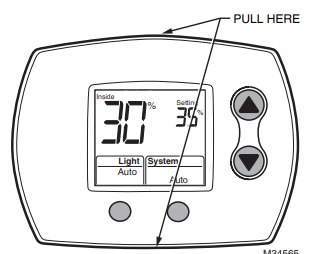
2. Separate wallplate from humidistat.
Caution: Electrical Hazard Can cause electrical shock or equipment damage. Disconnect power before beginning installation.
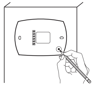
3. Mark the duct-tube hole.
Hold the wallplate up to the desired location on the duct and make a mark inside the duct tube hole.
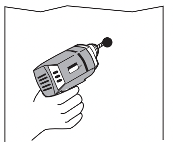
4. Drill the duct-tube hole.
Find your mark and drill a 1/2 in. hole in the duct. This is where the duct tube will be inserted to capture air.
5. Insert the duct tube.
Insert the duct tube through the wallplate before securing to the duct.
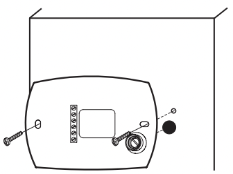
6. Secure the wallplate.
Secure the wallplate to the duct with sheet metal screws (provided).
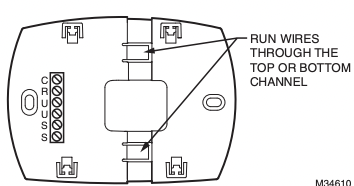
7. Run wires through the back plate.
Run wires through the top or bottom channel on the back plate when ductmounted. If installing like a thermostat on a wall, run the wires through the back.
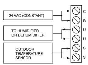
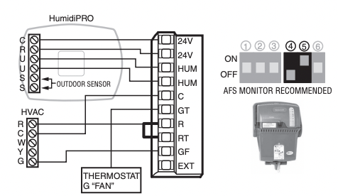
Wiring the Humidistat
This humidity control is wired the same way a manual humidistat (H8908) is wired. The only difference is that you also wire in power (24 VAC) and an outdoor sensor.
TERMINAL DESIGNATION
C 24 VAC POWER FROM EQUIPMENT
R 24 VAC POWER FROM EQUIPMENT
U HUMIDIFIER/DEHUMIDIFIER
U HUMIDIFIER/DEHUMIDIFIER
S OUTDOOR SENSOR
S OUTDOOR SENSOR
NOTES: C AND R MUST BE CONSTANT 24VAC! RECOMMENDED TO WIRE TO FURNACE/AIR HANDLER CONTROL BOARD.
DO NOT WIRE C AND R TO HUMIDIFIER TRANSFORMER!
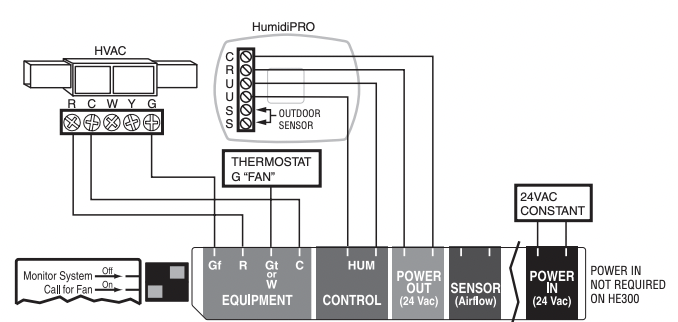
Wiring HumidiPRO with Fan Interlock
PROVIDE DISCONNECT MEANS AND OVERLOAD PROTECTION AS REQUIRED.
24 VAC WIRING.
Wiring HumidiPRO with Fan Interlock for 2 Speed Motor
PROVIDE DISCONNECT MEANS AND OVERLOAD PROTECTION AS REQUIRED.
24 VAC WIRING
Wiring HumidiPRO with Current Sensing Relay
PROVIDE DISCONNECT MEANS AND OVERLOAD PROTECTION AS REQUIRED
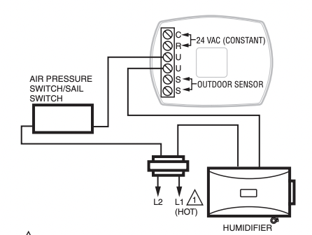
Wiring HumidiPRO with Sail/Pressure Switch
PROVIDE DISCONNECT MEANS AND OVERLOAD PROTECTION AS REQUIRED
Wiring HumidiPRO to FORCE FAN ON (Basic Humidifier)
NOTES: USE DPST RELAY FOR HUMIDITY ON DEMAND WITH A BASIC HUMIDIFIER.
HUMIDIFIER MUST BE PLUMBED TO HOT WATER WHEN FORCING FAN.
HONEYWELL ADVANCED HUMIDIFIERS DO NOT NEED A RELAY TO FORCE FAN.
Wiring HumidiPRO to TrueEASE Advanced Humidifier with Fan Interlock (HE150/HE250/HE300)
NOTE: SEE TrueEASE INSTALL GUIDE FOR DETAILED WIRING INFORMATION.
Wiring HumidiPRO to TrueSTEAM Advanced Humidifier
NOTE: SEE TrueSTEAM INSTALL GUIDE FOR DETAILED WIRING INFORMATION.
Wiring HumidiPRO to Dehumidifier
Mounting the Outdoor Sensor
(Not required if window protection isn’t needed)
Location
Mount the sensor where:
• it cannot be tampered with.
• there is good air circulation.
• surface is flat.
• wire distance between sensor and humidistat is less than 200 feet.
• it can measure true outdoor ambient temperature.
Do NOT mount the sensor:
in direct sunlight.
where snow, ice or debris can cover it.
where hot or cold air blows on the sensor. (For example, a discharge line from an outdoor compressor unit, vent or fan can cause inaccurate temperature readings.)
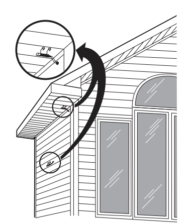
Steps to mount the sensor
Remove the sensor from the mounting clip.
Mark the area on the location selected for mounting the sensor mounting clip.
Mount the clip. Image on right shows typical locations for outdoor sensor.
Wiring the sensor
Caution Electrical Interference (Noise) Hazard. Can cause erratic system operation
Keep wiring at least one foot away from large inductive loads such as motors, line starters, lighting ballasts and large power distribution panels. Use shielded cable to reduce interference when rerouting is not possible.
Be sure wires have a cable separate from the thermostat cable.
Do not route temperature sensor wiring with building power wiring, next to control contactors or near light dimming circuits, electric motors or welding equipment.
Avoid poor wiring connections.
Avoid intermittent or missing building earth ground.
Caution Electrical Shock Hazard. Can cause electrical shock or equipment damage.
Disconnect power supply before connecting wiring. Wiring must comply with applicable codes, ordinances and regulations:
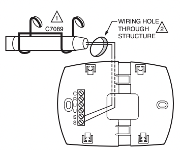
1. Wire the C7089 Outdoor Sensor to the S terminals on the humidity control. If leadwire provided with C7089 is not long enough (60 in.), run a cable to a hole at C7089 location.
• Using color-coded, 18-gauge, shielded thermostat wire is recommended. For example of general wiring of C7089, see image at right.
• Pigtail wiring can be used.
2. Mount C7089 in its mounting clip.
3. Plug wiring hole using nonhardening caulk or putty.
USE APPROPRIATE MOUNTING MEANS FOR THE TYPE OF STRUCTURE.
PLUG WIRING HOLE WITH NON-HARDENING CAULK OR PUTTY.
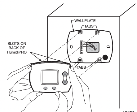
Mount Humidity Control
Align the 4 tabs on the wallplate with the slots on the back of the control, then push gently until the control snaps in place.
Checkout
Allow C7089B Outdoor Sensor to absorb outdoor air for a minimum of twenty minutes before taking a reading.
With an accurate thermometer (±1°F [0.5°C]), measure the temperature at the sensor location, allowing time for the thermometer to stabilize before reading.
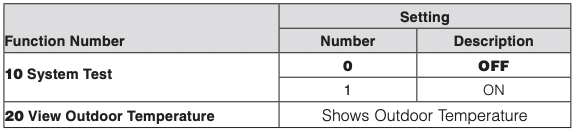
Then verify the sensor accuracy by going into installer Test #20. This will show you the outdoor temperature.
Calibration
The C7089 Outdoor Sensor is calibrated at the factory. However, you can offset the outdoor sensor reading using Function 35 in Installer Setup.
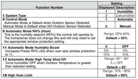
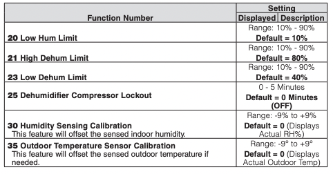
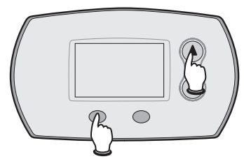
Advanced Installer Setup
Honeywell has already programmed this control to work properly in most applications. However, you can adjust the advanced settings by following the steps below.
To begin, press and hold theand LIGHT buttons until the display changes.
Press or to change settings.
Press NEXT to advance to the next function.
Press DONE to exit and save settings.
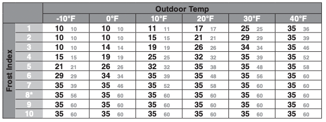
Honeywell HumidiPROTM Frost Index
*Black Numbers show highest humidity allowed when Default RH% (35%) is Selected.
Note: Smaller grey numbers show highest humidity allowed when Maximum RH% (60%) is selected.
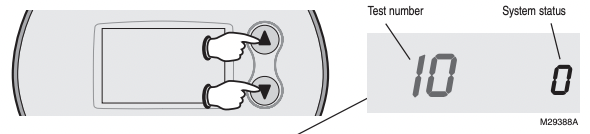
Installer System Test/Checkout
To begin, press and hold the and buttons until the display changes
Press / to turn system on/off.
Press NEXT to advance to next test.
Press DONE to terminate system test.
NOTE: Most humidifiers require airflow in the system to operate. Make sure to turn on the system fan when testing humidifier operation.
Caution: If running a dehumidifier, compressor protection is bypassed during testing; avoid cycling the compressor too quickly.
Note: Some dehumidifiers may already have built in compressor protection.
Troubleshooting
If you have difficulty with your humidity control, please try the following suggestions. Most problems can be corrected quickly and easily.
Display is blank
Check circuit breaker and reset if necessary.
Check for 24VAC between R and C at the wall plate.
Make sure power switch at heating and cooling system is on.
Make sure furnace door is closed securely.
Humidity settings do not change
Make sure the humidity is set to an acceptable range:
Check current range stop settings in Installer Setup.
Auto Mode: 1–10 (up to 11 if Humidity Boost is enabled)
Manual Mode: 20%–60%
Dehumidification Mode: 40%–80%
Humidifier/ Dehumidifier will not turn on
Make sure the equipment fan is running.
Make sure System Setting is ON.
Make sure there is power going to the Humidifier or Dehumidifier.
Check the humidity table to see if Window Protection is preventing a call for humidity. (Auto Humidification Mode Only).
Check whether Compressor Lockout is enabled.
Check whether High Temperature Shut-off is enabled (ISU-17) and Outdoor Temperature is less than selected Shut-off Temperature
 PROVIDE DISCONNECT MEANS AND OVERLOAD PROTECTION AS REQUIRED.
 24 VAC WIRING.
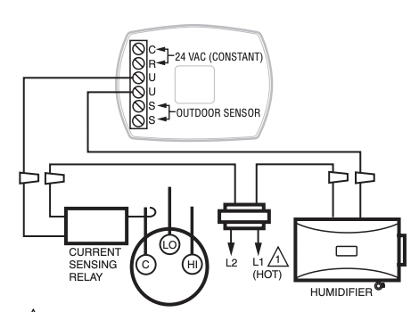

 and LIGHT buttons until the display changes.
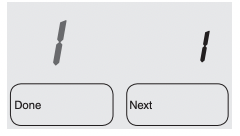
 or
or  to change settings.