
INSTALLATION
INSTRUCTIONS
36” and 48” Wall Hood
ZVW1360, ZVW1480
MONOGRAM.COM
Para consultar una version en español
de este manual de instrucciones, visite nuestro
sitio de internet monogram.com.
2 31-2000734 Rev. 0
Safety Information
READ AND SAVE THESE INSTRUCTIONS
BEFORE YOU BEGIN
Read these instructions completely and carefully.
■
IMPORTANT — Save these
instructions for local inspector’s use.
■
IMPORTANT — Observe all governing
codes and ordinances.
■
Note to Installer – Be sure to leave these
instructions with the Consumer.
■
Note to Consumer – Keep these instructions for
future reference.
■
Skill level – Installation of this vent hood
requires basic mechanical and electrical skills.
■
Completion time – Approximately 1 to 3 hours
■
Proper installation is the responsibility of the
installer.
■
Product failure due to improper installation is
not covered under the Warranty.
FOR YOUR SAFETY
WARNING
Before beginning the installation,
switch power off at service panel and lock the
service disconnecting means to prevent power
from being switched on accidentally. When the
service disconnecting means cannot be locked,
securely fasten a prominent warning device, such
as a tag, to the service panel.
CAUTION
Due to the weight and size
of these vent hoods and to reduce the risk
of personal injury or damage to the product,
TWO PEOPLE ARE REQUIRED FOR PROPER
INSTALLATION.
WARNING
Disconnect all electrical power
at the main circuit breaker or fuse box before
installing.
WARNING
TO REDUCE THE RISK OF FIRE,
ELECTRIC SHOCK OR INJURY TO PERSONS,
OBSERVE THE FOLLOWING:
A. Installation work and electrical wiring must be
done by qualified person(s) in accordance with all
applicable codes and standards, including fire-rated
construction.
B. Sufficient air is needed for proper combustion and
exhausting of gases through the flue (chimney) of
fuel burning equipment to prevent back drafting.
Follow the heating equipment manufacturer’s
guidelines and safety standards such as those
published by the National Fire Protection
Association (NFPA), the American Society for
Heating, Refrigeration and Air Conditioning
Engineers (ASHRAE) and the local code
authorities.
C. When cutting or drilling into wall or ceiling, do not
damage electrical wiring and other hidden utilities.
D. Ducted fans must always be vented to the
outdoors.
E. Turn off breaker to adjacent rooms while working.
WARNING
TO REDUCE THE RISK OF FIRE,
USE ONLY METAL DUCT WORK.
31-2000734 Rev. 0 3
Installation Preparation
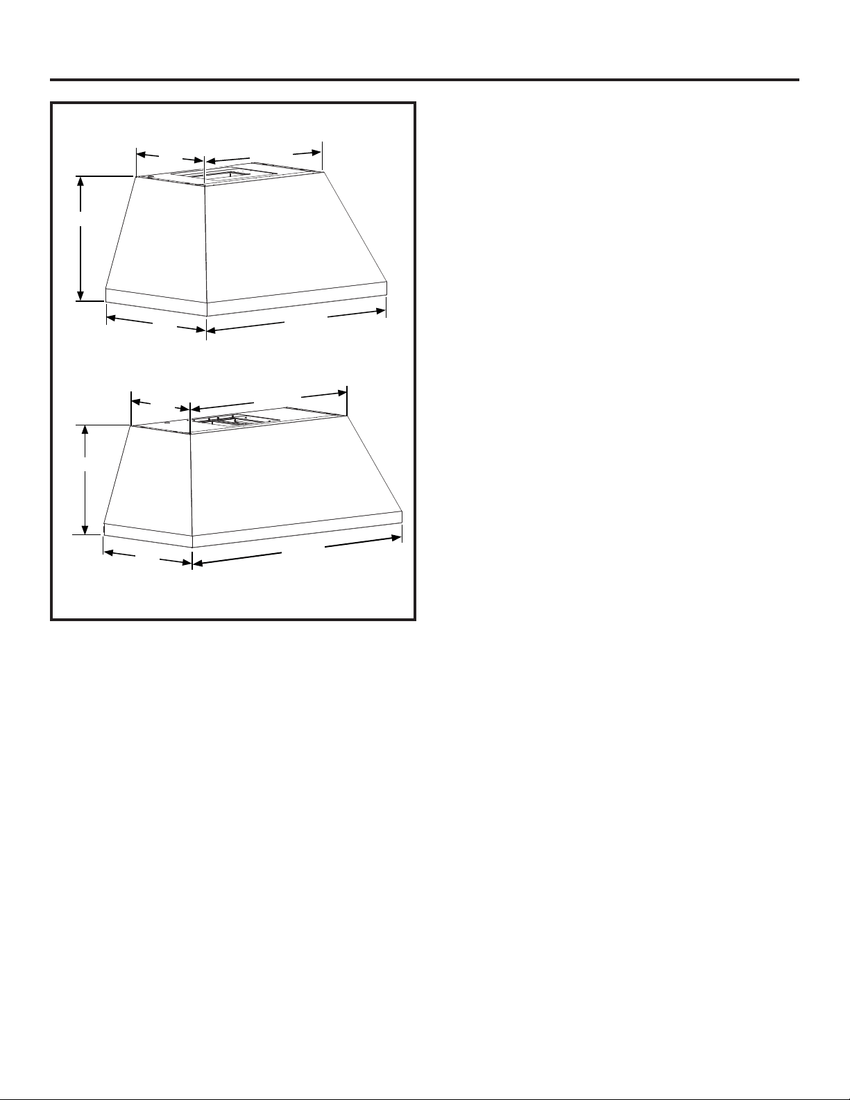
PRODUCT DIMENSIONS
36” Models
Requires a 36” opening.
48” Models
Requires a 48” opening.
18”
15”
23-5/8”
22”
36”
18”
22”
48”
15”
35-5/8”
4 31-2000734 Rev. 0
PLAN THE INSTALLATION
CAUTION
To reduce risk of fire and to properly
exhaust air, be sure to duct the air outside. Do not
vent exhaust air into spaces within walls or ceilings or
into attics, crawl spaces, or garages.
PARTS SUPPLIED FOR INSTALLATION
■ 1 Hardware Package
■ 1 Literature Package
■ 1 Installation Template
PARTS NEEDED FOR INSTALLATION
■ 1 Strain Relief
■ 1 Wall or Roof Cap
■ All Metal Ductwork
WARNING
PERSONAL INJURY HAZARD
Because of the weight and size of the rangehood
canopy. It is recommended that 2 people are used
to install the range hood. Failure to properly lift
rangehood could result in damage to the product or
personal injury.
NOTE: Before making any cuts or holes for
installation, determine which venting method will be
used and carefully calculate all measurements.
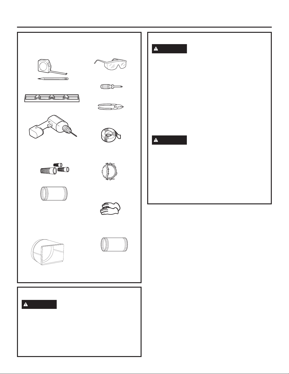
TOOLS AND MATERIALS REQUIRED
(NOT SUPPLIED)
REMOVE THE PACKAGING
CAUTION
Wear gloves to protect against sharp
edges.
■ Remove the hood body.
■ Remove the hardware bag, literature package and
other boxed parts.
■ Remove and properly discard the protective plastic
wrapping and other packaging materials.
Wire cutter/stripper
Level
Aluminized
duct tape
Safety glasses
Phillips screwdriver with
at least 6” shank
Strain relief for
junction box, 1”
diameter knockout
Strain Relief I
Electric drill with #2 Phillips
with 1/8” and 5/16” drill bits
UL listed wire nuts
Wire Nuts
Pencil and tape measure
Gloves
Installation Preparation
12" round duct
8”x12” to 12” round
duct transition
Needed for back venting only
10” round duct
31-2000734 Rev. 0 5
Installation Preparation
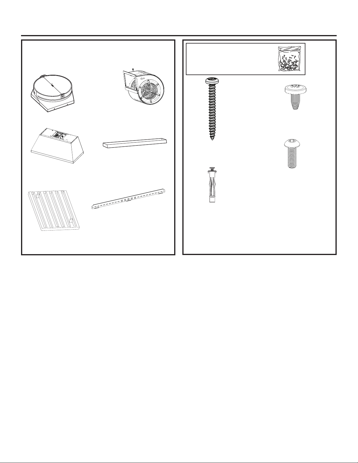
PARTS PROVIDED
Locate the parts packed with the hood.
HARDWARE PACKAGE
Locate and check contents.
Top Damper
761Dia28
Grease Drip Trays
Motor
(2 with 48” model)
Hood Body
Metal Installation Bracket
3 Baffle Filters
(4 with 48” models)
(QTY:2) 3/16” dry wall
anchors with screws. Used
for hood bottom mounting
screw holes. Use 5/16” drill
for pilot hole.
(QTY: 4 or 8) M4 screws.
Used to mount motor
(QTY: 4) 8 x 1-3/4 AB
screw. Used to mount the
installation bar. Use 1/8”
drill for pilot hole
(QTY: 4) 2.9mm x 6mm
PZ screws. Used to
attach the damper
A B
C
D
6 31-2000734 Rev. 0
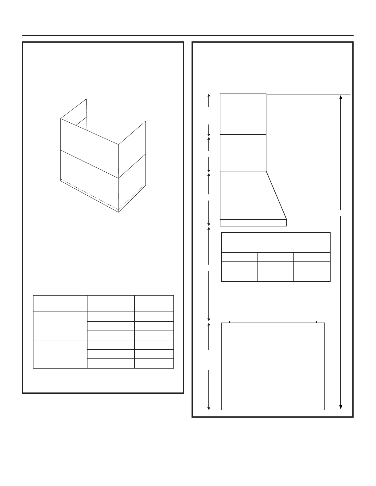
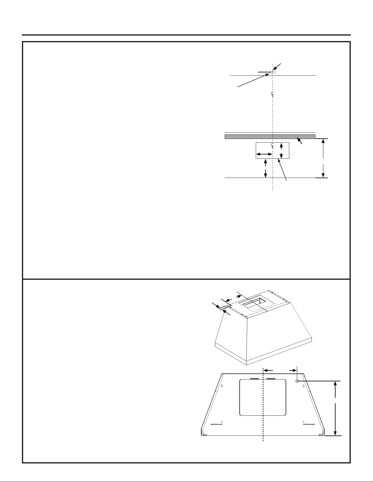
INSTALLATION DIMENSIONS
The hood duct covers can be adjusted for different
ceiling heights depending on the distance between the
bottom of the hood and the cooktop (distance X). See
Installation Height Table.
Installation Preparation
DUCT COVER REQUIREMENTS
Duct cover kits must be purchased separately.
We recommend that the vent hood and duct cover
(if used) be on site before final framing and wall
finishing. This will help to accurately locate studs,
ductwork and electrical service.
• Duct cover accessory comes with a lower and upper
duct cover and installation hardware.
• The installation hardware includes mounting
brackets to secure duct covers to the wall.
• The lower duct cover alone can be used and must
be secured with the duct cover bracket.
• See table below for duct cover kit part numbers
based on model.
• See the next page for duct cover installation height
information.
X = Distance from hood to cooktop. (Varies
depending on the installation) Required 24”
minimum over electric range or 30” minimum over
gas range. The recommended maximum is 36”.
Required Min & Recommended Max Ceiling
Height Examples for 10’ Duct Cover Kit
(Vented)
Electric Gas
X = 24”
Y = Min 8’ 3”
Max 9’ 6”
X = 30”
Y = Min 8’ 11”
Max 10’ 2”
X = 36”
Y = Min 9’ 5”
Max 10’ 8”
Typical Range
Upper Duct
Cover
1” Min.
16-1/2”
Max.
20”
18”
X
36”
or
38”
Lower Duct Cover
Model Duct Cover #
Max Ceiling
Installation
36” Model
ZX8D13SPSS 8’ 4”
ZX10D13SPSS 10’ 8”
ZX12D13SPSS 12’ 8”
48” Model
ZX8D14SPSS 8’ 4”
ZX10D14SPSS 10’ 8”
ZX12D14SPSS 12’ 8”
NOTE: 36” for typical
electric range and 38” for
gas range.
Y
31-2000734 Rev. 0 7
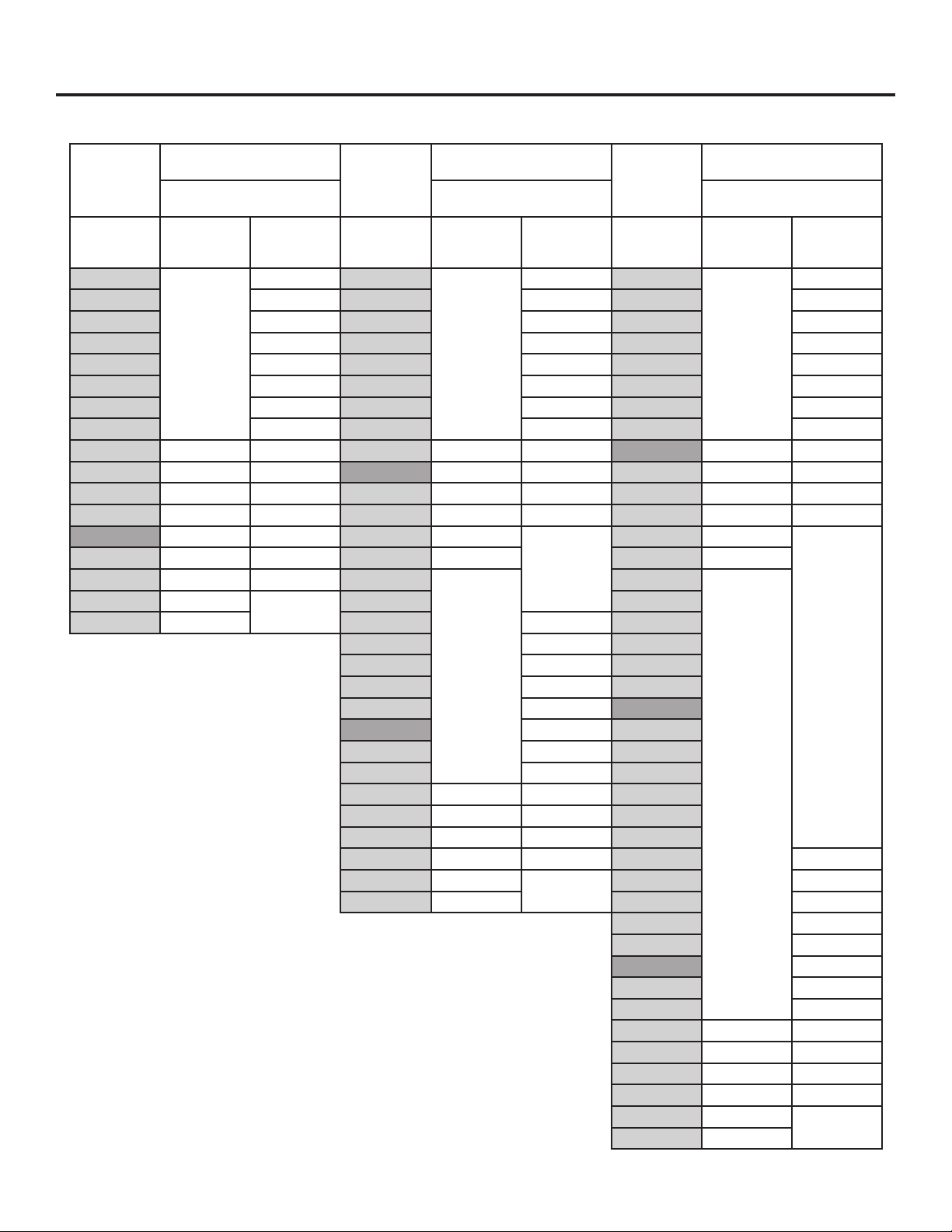
INSTALLATION HEIGHT TABLE
Installation Preparation
ZX8D13SPSS
OR ZX8D14SPSS
ZX10D13SPSS
OR ZX10D14SPSS
ZX12D13SPSS
OR ZX12D14SPSS
Ceiling Duct Cover up to 8 ft. High Ceiling Duct Cover up
to 10 ft.
High Ceiling Duct Cover up
to 12 ft.
Ceiling Height
(ft./in.)
Installation
Over Gas
Range
Installation
Over Electric
Range
Ceiling Height
(ft./in.)
Installation
Over Gas
Range
Installation
Over Electric
Range
Ceiling Height
(ft./in.)
Installation
Over Gas
Range
Installation
Over Electric
Range
7’ 0” 24 8’ 3” 24 9’ 4” 24
7’ 1” 24-25 8’ 4” 24-25 9’ 5” 24-25
7’ 2” 24-26 8’ 5” 24-26 9’ 6” 24-26
7’ 3” 25-27 8’ 6” 24-27 9’ 7” 24-27
7’ 4” 26-28 8’ 7” 24-28 9’ 8” 24-28
7’ 5” 27-29 8’ 8” 24-29 9’ 9” 24-29
7’ 6” 28-30 8’ 9” 24-30 9’ 10” 24-30
7’ 7” 29-31 8’ 10” 24-31 9’ 11” 24-31
7’ 8” 30 30-32 8’ 11” 30 24-32 10’ 0” 30 24-32
7’ 9” 30-31 31-33 9’ 0” 30-31 24-33 10’ 1” 30-31 24-33
7’ 10” 30-32 32-34 9’ 1” 30-32 24-34 10’ 2” 30-32 24-34
7’ 11” 31-33 33-35 9’ 2” 30-33 24-35 10’ 3” 30-33 24-35
8’ 0” 32-34 34-36 9’ 3” 30-34
24-36
10’ 4” 30-34
24-36
8’ 1” 33-35 35-36 9’ 4” 30-35 10’ 5” 30-35
8’ 2” 34-36 36 9’ 5”
30-36
10’ 6”
30-36
8’ 3” 35-36 9’ 6” 10’ 7”
8’ 4” 36 9’ 7” 25-36 10’ 8”
9’ 8” 26-36 10’ 9”
9’ 9” 27-36 10’ 10”
9’ 10” 28-36 10’ 11”
9’ 11” 29-36 11’ 0”
10’ 0” 30-36 11’ 1”
10’ 1” 31-36 11’ 2”
10’ 2” 32-36 11’ 3”
10’ 3” 31-36 33-36 11’ 4”
10’ 4” 32-36 34-36 11’ 5”
10’ 5” 33-36 35-36 11’ 6”
10’ 6” 34-36 36 11’ 7” 25-36
10’ 7” 35-36 11’ 8” 26-36
10’ 8” 36 11’ 9” 27-36
11’ 10” 28-36
11’ 11” 29-36
12’ 0” 30-36
12’ 1” 31-36
12’ 2” 32-36
12’ 3” 31-36 33-36
12’ 4” 32-36 34-36
12’ 5” 33-36 35-36
12’ 6” 34-36 36
12’ 7” 35-36
12’ 8” 36
8 31-2000734 Rev. 0
Installation Preparation
ADVANCE PLANNING
Duct Install Planning
■ This hood is designed to be vented vertically
through the ceiling with a 10” round duct or,
horizontally through a wall with an 8”x12” duct
transition and 12” round duct.
■ Use metal ductwork only.
■ Plan the route for venting exhaust to the outdoors.
To maximize the ventilation performance of the vent
system:
1. Minimize the duct run length and number of
transitions and elbows.
2. Maintain a constant duct size.
3. Seal all joints with duct tape to prevent any leaks.
NOTE: Flexible vent is not recommended. Flexible
vent creates back pressure and air turbulence that
greatly reduces performance.
■ Maximum equivalent duct length for 100 CFM:
150 foot for vent hoods.
■ Install a wall cap or roof cap with damper at the
exterior opening. Purchase the wall or roof cap and
any transition and length of duct needed in advance.
■ When applicable, install any makeup (replacement)
air system in accordance with local building code
requirements. 10” round duct universal make up air
kit can be purchased locally.
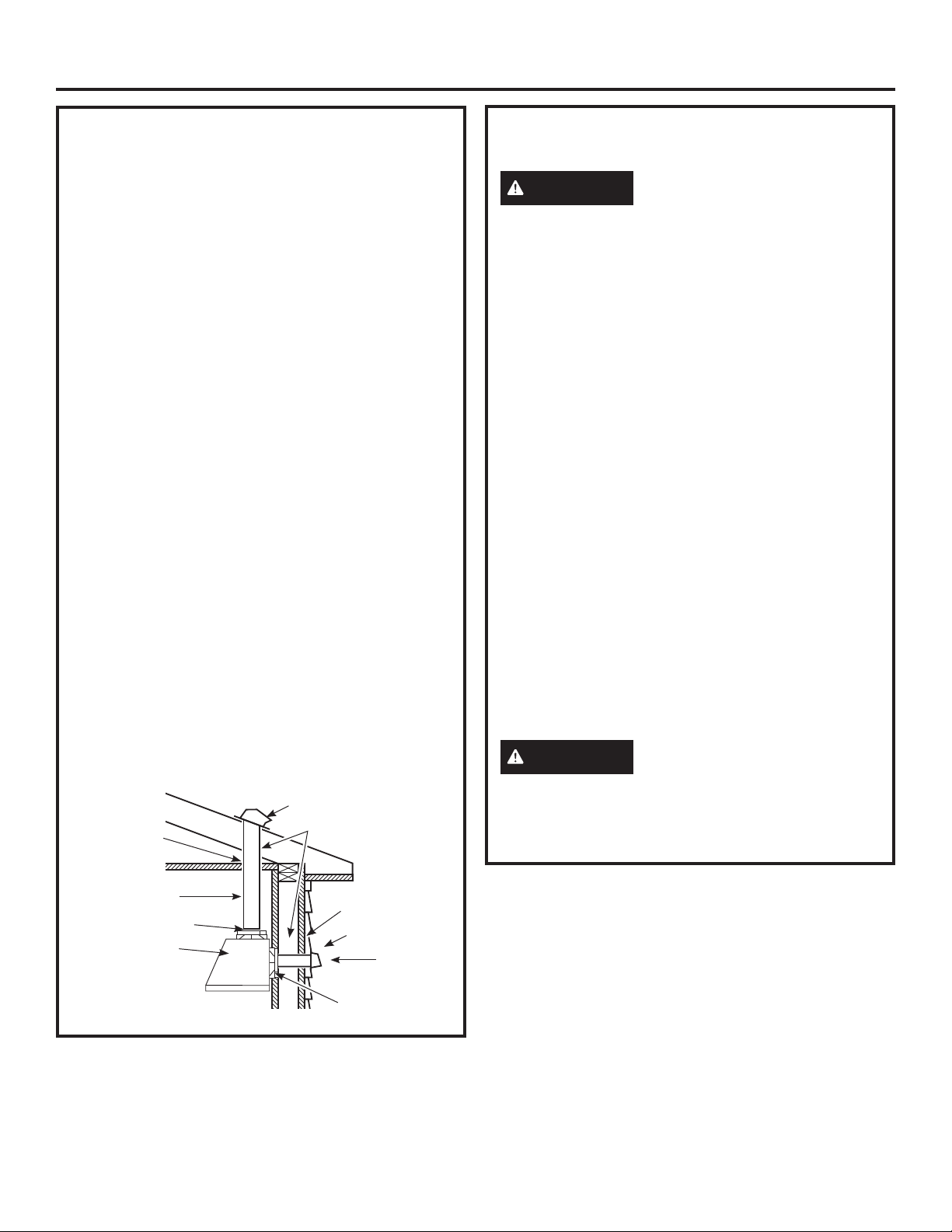
Vent system can terminate either through the roof
or the wall.
POWER SUPPLY
IMPORTANT – (Please read carefully)
WARNING
FOR PERSONAL SAFETY, THIS APPLIANCE MUST
BE PROPERLY GROUNDED.
Remove house fuse or open circuit breaker before
beginning installation.
Do not use an extension cord or adapter plug with
this appliance. Follow National Electrical Codes or
prevailing local codes and ordinances.
Electrical supply
These vent hoods must be supplied with 120V, 60Hz,
and connected to a properly grounded branch circuit,
and protected by a 15 or 20 amp circuit breaker or
time delay fuse.
■ Wiring must be 2 wire with ground.
■ If the electrical supply does not meet the above
requirements, call a licensed electrician before
proceeding.
■ Route house wiring as close to the installation
location as possible in the ceiling or wall.
■ Connect the wiring to the house wiring in
accordance with local codes.
Grounding instructions
The grounding conductor must be connected to
a ground metal, permanent wiring system, or an
equipment-grounding terminal or lead on the hood.
WARNING
The improper connection of the
equipment-grounding conductor can result in a risk
of electric shock. Check with a qualified electrician or
service representative if you are in doubt whether the
appliance is properly grounded.
Roof Cap
Round Duct
Wall Cap
Add Insulation
and/or Caulk
Add tape to joint
Hood
Top Venting Setup
Add Tape to
Joint
Add Insulation
and/or Caulk
Back Venting
Setup
31-2000734 Rev. 0 9
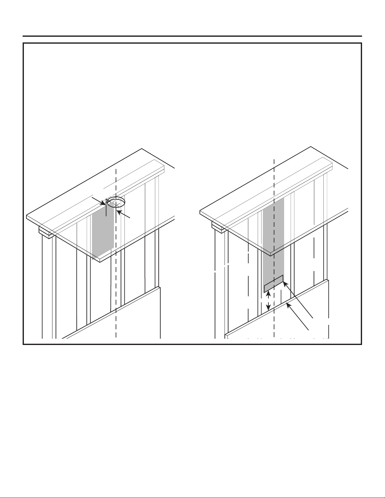
NEW CONSTRUCTION, PRE-PLANNING, OR REMODELING
NOTE: For existing instruction, skip to the next section.
FOR TOP VENTING
■Forductedinstallationthroughthetop,the10”
diameter hole for the duct in the ceiling must be
centered 6-1/4” away from the finished rear wall in the
installation space.
FOR BACK VENTING
■Forductedinstallationthroughtheback,the
10-1/2”x13-1/4” cut out for the duct in the wall must
be centered in the installation space, left to right and
located 5-7/8” above intended install height from
bottom of the hood.
Installation Preparation
6-1/4”
5-7/8”
10-1/2”x13-1/4”
Bottom of Hood
■Thehoodjunctionboxknockoutislocated10-1/2”tothe
left from center of the hood. Ensure enough wire length is
available to make electrical connection.
10 31-2000734 Rev. 0
Installation Preparation
DETERMINE HOOD, DUCTWORK AND WIRING LOCATIONS
• This hood can be installed onto the wall or underneath
the soffit.
• For installing the hood to soffit, refer to page 12 for
alternate mounting method.
• A wall mounting template is included with the product
for ease of installation. Follow the instructions below if
the template is not being used.
• Measure desired distance from the bottom of the hood
to the cooking surface, 24” minimum over electric range
or 30” minimum over gas range and 36” recommended
maximum.
• Use a level to draw the cooktop centerline location.
• Measure 16-3/4” up from the horizontal line indicating
the bottom of the hood. Draw another horizontal line to
indicate the bottom of the installation bar.
• Use a level to draw the cooktop or range centeline
location.
For Ceiling Ducting:
• If venting out the ceiling, extend the centerline forward
on the ceiling to the back wall.
- Measure 6-1/4” from back wall to mark center point.
- Cut 10” dia. duct hole from center point on the
ceiling.
Venting Through a Soffit:
• Follow the same procedure for ceiling ducting to cut
the hole through the top of the soffit.
For Ducting Through Rear Wall:
NOTE: Check to make sure back damper will not
interfere with studs, electrical or plumbing before making
cut out.
• Back damper accessory UXBDA812 must be
purchased separately for venting through the rear wall.
• Measure 5-7/8” up along the centerline from the
horizontal line indicating bottom of the hood.
• Make an 10-1/2”x13-1/4” cut out centered left to right
along the centerline.
House Wiring Location:
• The junction box is located inside the hood body on the
left side. See Illustrations for hood knockout locations.
House wiring may enter the junction box from the rear or
the top of the hood on the left side.
To route house wiring through the ceiling or soffit:
• Cut a hole approximately 1-1/4” dia. forward on the
ceiling 10-1/4” to the left of the centerline.
To route house wiring through the wall:
NOTE: For back venting, the house wiring must be
routed through the rear knockout so it is hidden.
• Measure 15-3/4” from the bottom of the hood and mark
location
• Cut a hole approximately 1-1/4” dia. at the marked
location at a distance 10-1/4” to the left of the
centerline based on table below.
• Remove top or rear knockout depending on your
installation.
Centerline to Wall
FOR CEILING VENT
DUCTING
Duct Hole
Top of Hood
Installation
Bar
Bottom of Hood
FOR REAR WALL DUCTING
6-5/8”
5-7/8”
10-1/2”
16-3/4”
1-1/4”
Top View
Rear View
10-1/4”
10-1/4”
15-3/4”
31-2000734 Rev. 0 11
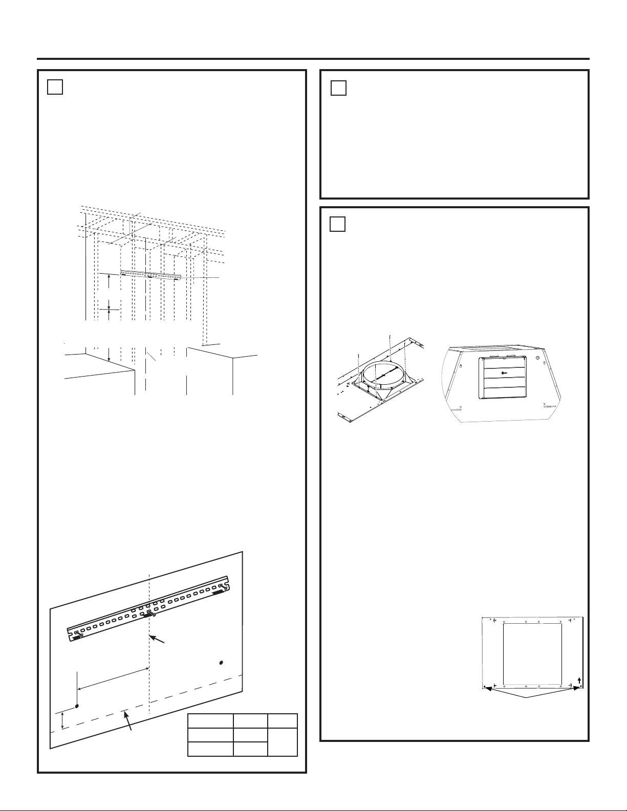
Installation
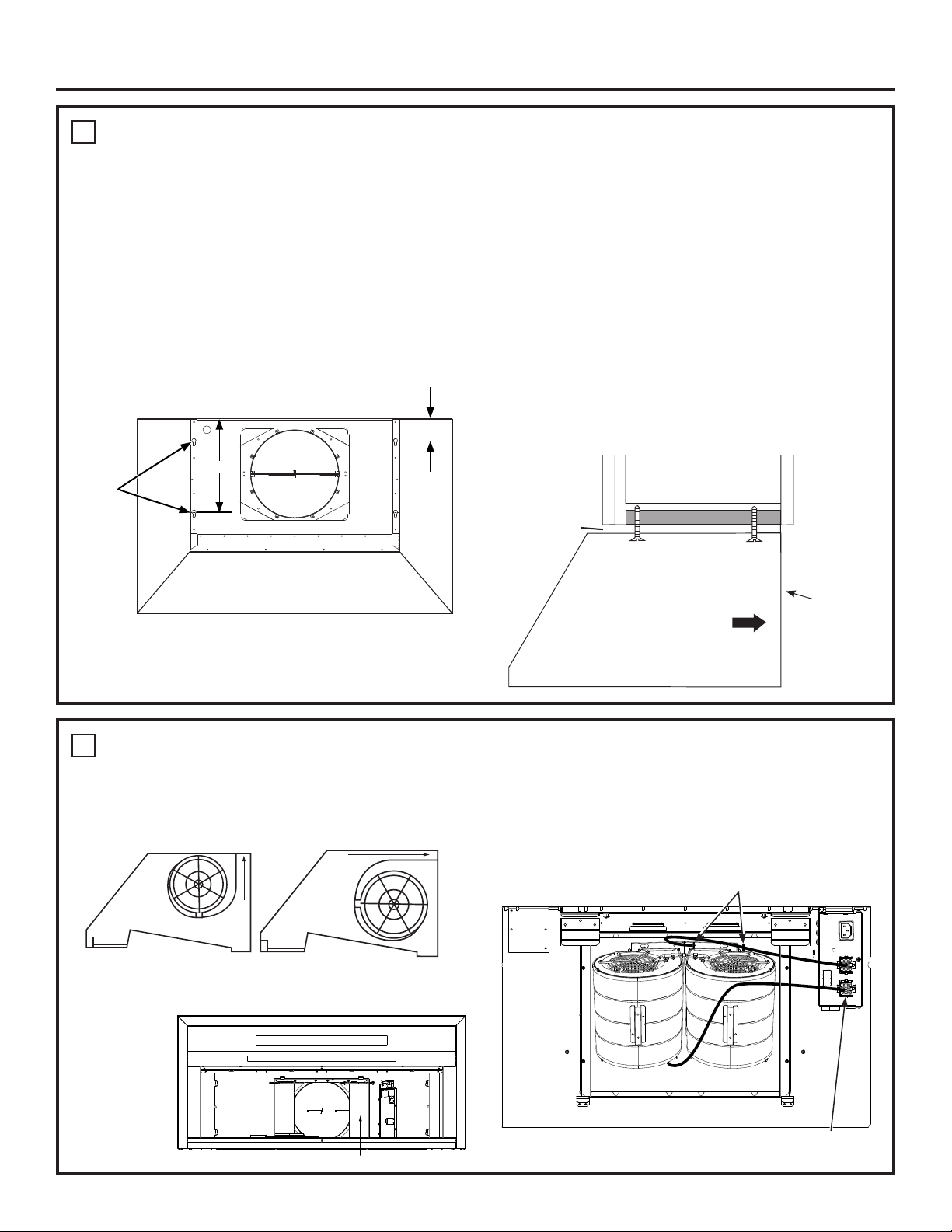
1
INSTALL HOOD SUPPORT
IMPORTANT: Framing must be capable of supporting
100 lbs for 36” models and 150 lbs for 48” models.
• Locate a minimum of 2 vertical studs for the
installation bar by tapping drywall with a hammer or
use a stud finder.
• Level the installation bar and center left to right
above the marked line. Hold bar against the wall.
• Drill 1/8” pilot holes at the 2 vertical stud locations
through holes in the installation bracket. Secure the
installation bar with supplied screws (A) as shown
above.
Drill Bottom Mounting Hole Locations:
• Hang hood on installation bar or use the table below
to mark the screw hole locations. NOTE: If installing
to the soffit, push hood flush to the soffit before
marking screw hole locations.
• Remove the hood and drill 5/16” clearance holes at
marked locations “A” and “B”.
2
INSTALL DAMPER
IMPORTANT: Remove shipping tape from damper
and check that damper moves freely.
Install Top Damper:
• The motor mounting plate comes pre-installed in the
hood for top venting.
• Install the top damper to the hood body as shown in
Figure A using screws (B) from top of hood.
Install Back Damper:
• In case of back venting through the wall, back
damper accessory UXBDA812 must be purchased
separately.
• Uninstall the motor mounting plate from top venting
position. Save the screws.
• Remove the square knockout panel on hood body for
back venting.
• Remove the two screw knockout holes on the motor
mounting plate as shown in Figure C.
• Install the motor mounting plate to back panel so that
the arrow on plate is pointing upwards and on the
right side.
• Push plate in until metal clips
engage. Fasten plate through
screw knockouts shown in
Figure C using the two screws
saved.
• Install the back damper to the
hood body as shown in Figure
B using screws provided with
the accessory.
• Install the metal plate provided with the accessory to
cover the opening for top damper.
Installation Bar
Centerline of
Installation Space
16-3/4”
24” minimum over electric range
or cooktop, or 30” minimum over
gas range or cooktop, and 36”
recommended maximum.
Figure A
Figure B
1
INSTALL HOOD SUPPORT (Cont.)
• Install wall anchors (C) by tapping the anchors with
a hammer to seat the teeth of the flanges into the
wall. This keeps anchor from rotating.
• Drive the anchor screws until the barrels crimp
against the inside of the wall.
• Remove the screws from the wall anchors before
installing the hood.
B
A
Bottom of Hood
Centerline of
Installation Space
“A” “B”
36” Model 11-7/8”
4”
48” Model 17-3/4”
TOP
Figure C (Panel will look
different for single motor)
Screw Knockouts
12 31-2000734 Rev. 0
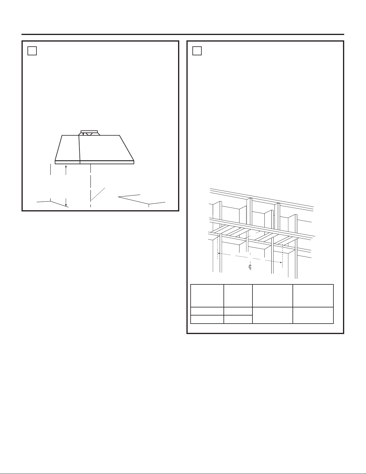
Installation
4
(Alternate Mounting Method)
INSTALL HOOD TO SOFFIT
SKIP THIS STEP IF USING WALL MOUNTING
METHOD
IMPORTANT: Soffit framing must be capable of
supporting 100 lbs for 36” models and 150 lbs for
48”models.
When necessary the hood may be installed so that it
is supported by the soffit.
• The soffit should be constructed with 2”x4”s.
• Use a level to draw the cooktop or range center line.
• Continue the centerline forward on the bottom of the
soffit.
• Install horizontal wood supports between the 2”x4”,
at distance A to the left and right, as per the table
below.
B
A
A
“A”
Centerline
to Center
Stud
“B”
Opening for
Ductwork for
top venting
“C”
Opening for
Ductwork for
back venting
36” Models 11-3/8”
10-5/8”x11-1/4” 10-1/2”x13-1/4”
48” Models 17-3/8”
C
3
INSTALL HOOD ONTO WALL
• Pull house wiring through knockout at the back or
top of the hood.
• Lift the hood and place over the hooks on the
installation bar. Allow the hood to slide down into
position.
• Check to be sure the hood is level and centered.
• Tighten wall anchor screws (C) to finish hood body
installation to the wall.
• Remove cover from junction box inside the hood.
Centerline of
Installation Space
24” minimum over electric
range or cooktop, or 30”
minimum over gas range
or cooktop, and 36”
recommended maximum.
31-2000734 Rev. 0 13
Installation
4
(Alternate Mounting Method) INSTALL HOOD TO SOFFIT (Cont.)
• Drill two 1/8” pilot holes at a distance of 10-5/8” from
the back wall in the horizontal wood supports. This is
the vertical distance between mounting keyholes and
back wall as shown in Figure C.
• Drill two more 1/8” pilot holes at a distance of 2-1/2”
from the back wall in the horizontal wood supports.
This is the vertical distance between mounting screw
holes and back wall as shown in Figure C.
• For top venting, allow minimum opening (Dim. B) to
accommodate damper in soffit.
• For back venting, allow minimum opening (Dim. C) to
accommodate damper in back wall
• Drive mounting screws (A) into the studs until they
protrude 1/4”. This 1/4” gap will provide clearance to
engage the keyhold slots in the top of the hood.
• The hood must also be secured to the back wall.
Follow instruction on page 11, “Drill Bottom Mounting
Hole Locations” for installation to the back wall.
• Follow instructions on page 10 “House Wiring
Locations” for wiring setup.
• Lift hood onto mounting screws. Slide back against the
rear wall.
• Pull house wiring through the knockout at the rear or
top of the hood.
• Tighten mounting screws (E).
• Once the hood is secured to the soffit, drive screws (C)
to secure the hood to the back wall.
1/4” Gap
Soffit
Back
Wall
Engage Keyhole Slots
and Push Back at Wall
2-1/2”
Back Wall
Figure C
10-5/8”
Keyholes
for Soffit
Mounting
5
INSTALL MOTOR
I) Align the motor exhaust with the top damper as shown
in the Figure A for top venting. In case of back venting,
rotate the motor 90° to align with the back damper as
shown in Figure B.
II) Secure the motor to motor mounting plate using
screws (D).
III) Plug the motor connector into the mating connector
on top of the control housing.
IV) Repeat steps I through III for dual motor models.
V) For dual motor models, secure the right side motor
wire to wire clips as shown in image below.
Motor Mounting Plate
Top Venting
Figure A
Back Venting
Figure B
Wire Clips
Motor Mating
Connector Location
Dual Motor Top Venting Installation
14 31-2000734 Rev. 0
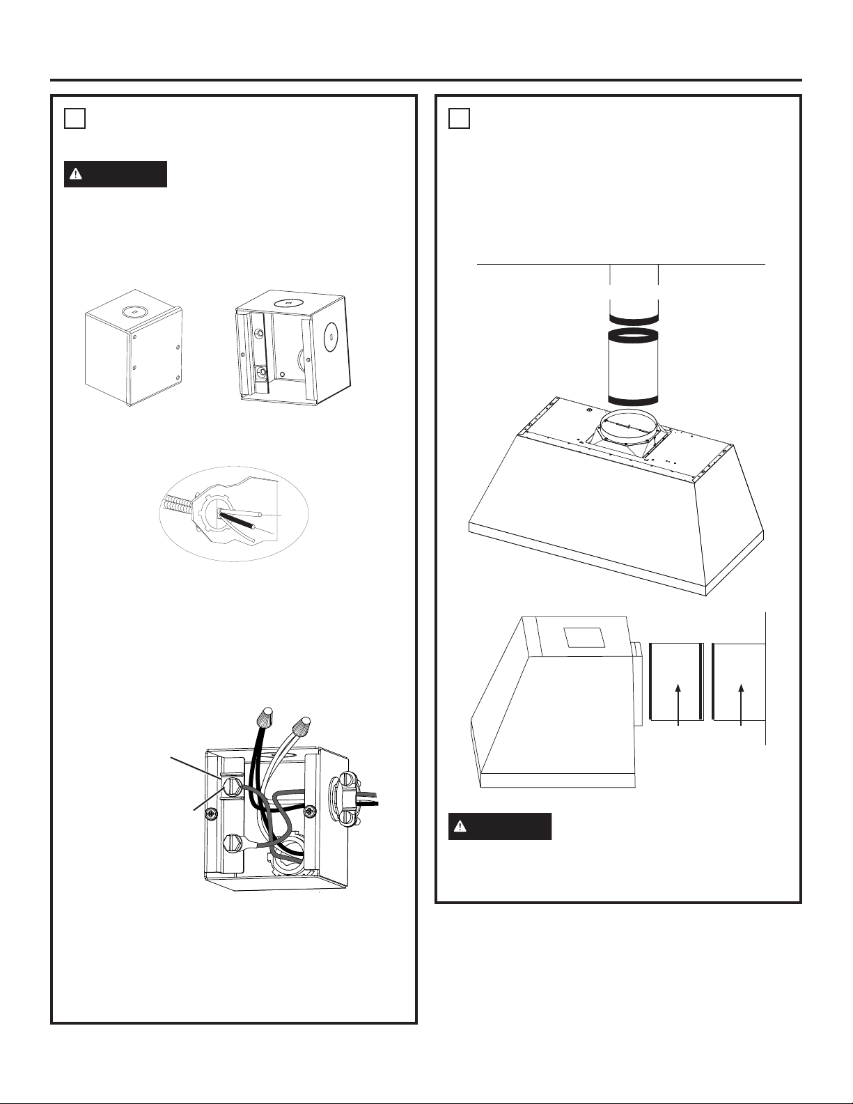
Installation
6
CONNECT ELECTRICAL
Verify that power is turned off at the source.
WARNING
If house wiring is not 2-wire with
a ground wire, a ground must be provided by the
installer. When house wiring is aluminum, be sure
to use UL approved anti-oxidant compound and
aluminum-to-copper connectors.
• Remove junction box cover.
• Pull the house wiring through the knockout at the top
or back of the hood and secure with the strain relief.
• Use UL listed wire nuts to connect incoming white to
white, and black to black wires.
• Loosen the green grounding screw (with grounding
bracket) in the junction box. Loop solid copper house
wire clockwise around the green grounding screw
and above the bracket. Firmly tighten the screw over
the loop.
• Replace junction box cover and ensure wires are not
pinched.
NOTE: For corded installation:
Use only with rangehood cord-connection kits that
have been investigated and found acceptable for use
with this model rangehood.
7
CONNECT DUCTWORK
• Connect the house ducting to the top damper as
shown in Figure A.
• For back venting, connect the transition piece to the
back damper and the house ducting to the transition
as shown in Figure B.
• Seal all connections with duct tape.
CAUTION
Do not use sheet metal screws at
the transition to ductwork connection. Doing so will
prevent proper damper operations. Seal connection
with tape only.
Ceiling
Figure A
House Ducting
Wall
House
Ducting
Duct
Transition
Figure B
Grounding Bracket
Green Grounding Screw
31-2000734 Rev. 0 15
MAKE UP AIR TECHNOLOGY
This operation must be performed by a qualified technician or installer.
Note to Installers and Inspectors: This product comes equipped with a simple installation feature that limits
maximum CFM levels in order to comply with certain local codes or regulations. This installation method may not be
necessary for all installations, please refer to your local codes for further guidelines.
This makeup air feature applies to single motor models only.
CAUTION
Hood must be disconnected from main power prior performing the conversion instructions listed
below. Failure to do so could result in personal injury or damage to the product.
To modify unit (if needed for local codes):
390CFM
By design, the maximum blower speed is greater than 400 CFM. For local
codes requiring reduced CFM, modify the wiring as described below:
1. Remove the Baffle filters.
2. Disconnect all the harnesses from the top of control box on right side of
motor
3. Loosen the screws on top of control box and slide out to remove it from
the hood
4. Uninstall the control box cover
5. For a maximum of 390 CFM Unit can operate with 4 speeds (Low,
Medium, High, Boost).
i. Disconnect connectors of the BROWN wire.
ii. Remove the cap attached to the connector of the RED wire.
iii. Connect the mating connector of the BROWN wire and the
RED wire.
iv. Attach the cap to the open BROWN wire connector.
6. Reinstall control box cover and secure control box to the bracket in
the hood using the two screws
7. Connect all harnesses on top of the control box
8. Reinstall filters.
Note to Inspectors: To verify this product installation, check motor
wiring connections as described above.
Installation
8
INSTALL DUCT COVERS
• Refer to section “Duct Cover Requirements” on
page 6 for duct cover accessory part numbers.
• Follow instructions included with the duct cover
accessory to install duct covers.
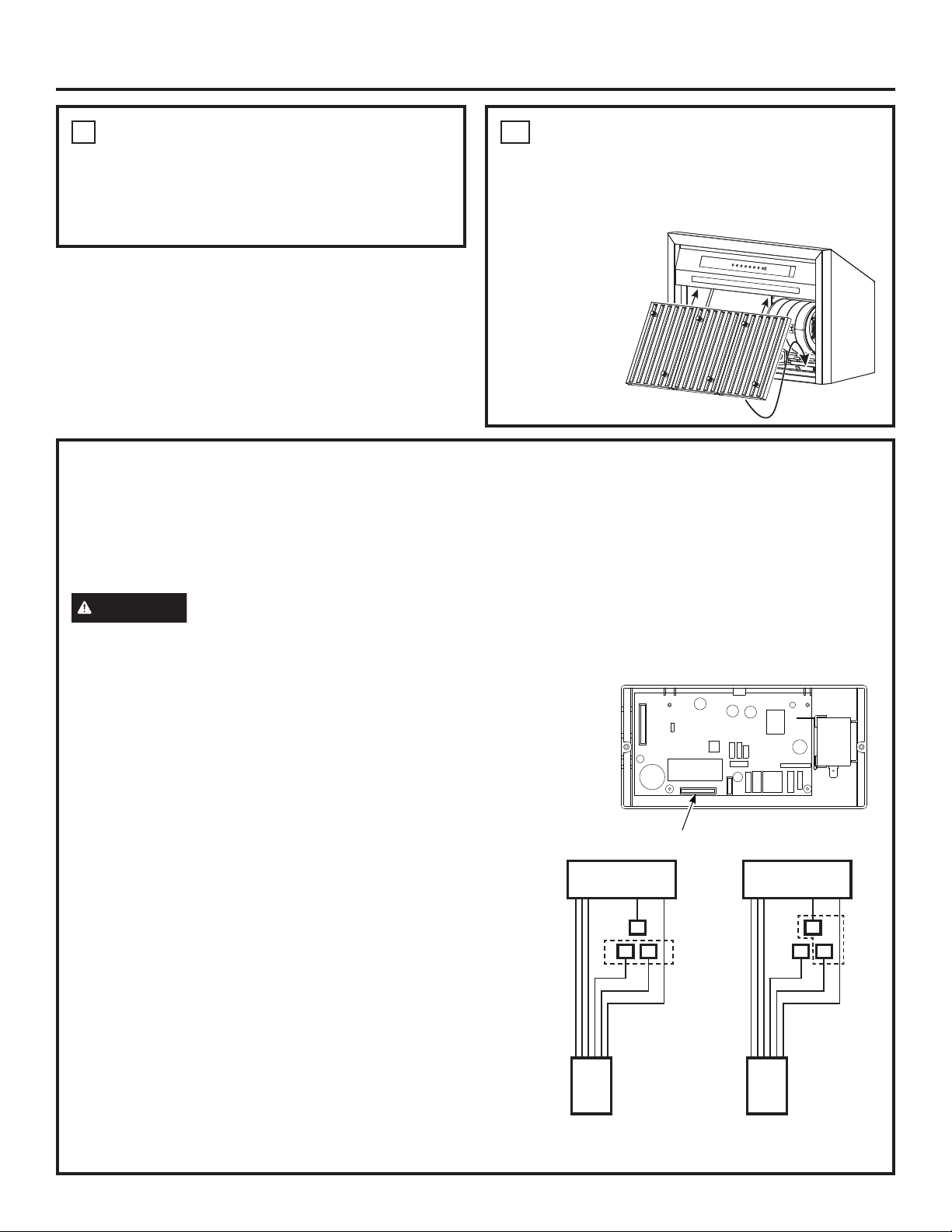
9
INSTALL GREASE TRAYS AND
FILTERS
• Remove protective film.
• Place grease drip trays into slots.
• Install the baffle
filters.
• Refer to
the Use &
Care manual
for further
instructions to
install grease
drip trays and
baffle filters.
1
2
Motor Harness Connector
Blue
Red
Red
Motor Harness
Brown
Brown
Blue
Red
Red
Motor Harness
Brown
Brown
Factory Installed
Wiring Setup
Max 390 CFM Boost
Wiring Setup

31-2000734 Rev. 0
03-21 GEA
Printed in Mexico
NOTE: While performing installations described in this book, safety glasses or
goggles should be worn.
NOTE: Product improvement is a continuing endeavor at Monogram. Therefore,
materials, appearance and specifications are subject to change without notice.
