Ion Series Abdominal / Back Extension
Assembly Instructions
CI-ABBA
Part Number
1017130-0001 AA


Corporate Headquarters
Columbia Centre III, 9525 Bryn Mawr Avenue, Rosemont, Illinois 60018 • U.S.A.
847.288.3300 • FAX: 847.288.3703
Service phone number: 800.351.3737 (toll-free within U.S.A., Canada)
Global Website: www.lifefitness.com
International Oices
AMERICAS
North America
Life Fitness, LLC
Columbia Centre III
9525 Bryn Mawr Avenue
Rosemont, IL 60018 U.S.A.
Telephone: (847) 288 3300
Service Email: [email protected]om
Sales/Marketing Email:
commercialsales@lifefitness.com
United Kingdom
Life Fitness UK LTD
Queen Adelaide
Ely, Cambs, CB7 4UB
Telephone: General Oice (+44) 1353.666017
Customer Support (+44) 1353.665507
Service Email: [email protected]
Sales/Marketing Email: lif[email protected]om
All Other EMEA Countries and Distributor Business
EMEA*
Bijdorpplein 25-31
2992 LB Barendrecht
THE NETHERLANDS
Telephone: (+31) 180 646 644
Service Email:
Brazil
Life Fitness Brasil
Av. Rebouças, 2315
Pinheiros
São Paulo, SP 05401-300
BRAZIL
SAC: 0800 773 8282 option 2
Telephone: +55 (11) 3095 5200 option 2
Service Email: [email protected]om
Sales/Marketing Email: vendasbr@lifefitness.com
Germany, Austria, and Switzerland
Life Fitness Europe GMBH
Neuhofweg 9
85716 Unterschleißheim
GERMANY
Telephone:
+49 (0) 89 / 31775166 Germany
+43 (0) 1 / 6157198 Austria
+41 (0) 848 / 000901 Switzerland
Service Email: [email protected]om
Sales/Marketing Email: vertrieb@lifefitness.com
ASIA PACIFIC (AP)
Japan
Life Fitness Japan, Ltd
4-17-33 Minami Aoyama 1F/B1F
Minato-ku - Tokyo 107-0062
Japan
Telephone: (+81) 0120.114.482
Fax: (+81) 03-5770-5059
Service Email: service.lfj@lifefitness.com
Sales/Marketing Email:
sales@lifefitnessjapan.com
Latin America and Caribbean*
Life Fitness, LLC
Columbia Centre III
9525 Bryn Mawr Avenue
Rosemont, IL 60018 U.S.A.
Telephone: (847) 288 3300
Service Email: [email protected]om
Sales/Marketing Email:
commercialsales@lifefitness.com
Spain
Life Fitness IBERIA
C/Frederic Mompou 5,1º1ª
08960 Sant Just Desvern Barcelona
SPAIN
Telephone: (+34) 93.672.4660
Service Email: servicio.tecnico@lifefitness.com
Sales/Marketing Email:
info.iberia@lifefitness.com
Hong Kong
Life Fitness Asia Pacific LTD
32/F, Global Trade Square
21 Wong Chuk Hang Road
Hong Kong
Telephone: (+852) 2575.6262
Service Email: Service.HK@lifefitness.com
Sales/Marketing Email:
hongkong.sales@lifefitness.com
EUROPE, MIDDLE EAST, and AFRICA (EMEA)
Netherlands and Luxemburg
Life Fitness Atlantic BV
Bijdorpplein 25-31
2992 LB Barendrecht
THE NETHERLANDS
Telephone: (+31) 180 646 666
Service Email: service.benelux@lifefitness.com
Sales/Marketing Email:
marketing.benelux@lifefitness.com
Belgium
Life Fitness Benelux NV
Parc Industrial de Petit-Rechain
4800 Verviers
BELGIUM
Telephone: (+32) 87 300 942
Service Email: service.benelux@lifefitness.com
Sales/Marketing Email:
marketing.benelux@lifefitness.com
All Other Asia Pacific countries and distributor
business Asia Pacific*
32/F, Global Trade Square
21 Wong Chuk Hang Road
Hong Kong
Telephone: (+852) 2575.6262
Fax: (+852) 2575.6894
Service Email: Service.AP@lifefitness.com
Sales/Marketing Email:
Marketing.HK.Asia@lifefitness.com
*Also check
www.lifefitness.com for local representation or distributor/dealer
Page 1 of 38

User and Service Documents Link
https://lifefitness9512.zendesk.com/hc/en-us
https://www.lechsupport.com/web/document-library/documents
Additional information is available online using the links above.
. رفوت
ت
تامولعم ةي
ف
اض
إ ع تنن
إ مإدخت
س
طبإرلإ هع
أ
点击上面的链接可在线获取更多信息。
Flere oplysninger er tilgængelige online gennem linket ovenfor.
Bijkomende informatie is online beschikbaar via bovenstaande link.
Vous trouverez plus d'informations en ligne à l'aide du lien ci-dessus.
Zusätzliche Informationen finden Sie online über den oben angegebenen Link.
Ulteriori informazioni sono disponibili online utilizzando il link sopra riportato.
追加情報は上記リンクを使用してオンラインで利用可能です。
상기 링크를 통해 온라인에서 추가 정보를 볼 수 있습니다.
Informações adicionais estão disponíveis on-line, através do link acima.
Дополнительная информация доступна в интернете по ссылке, указанной выше.
Mediante el enlace anterior podrá acceder a información adicional en línea.
Ytterligare information finns online genom att använda länken ovan.
İnternet üzerinden daha fazla bilgi edinmek için yukarıdaki bağlantıyı kullanabilirsiniz.
. كان
ه
تامولعم ةي
ف
اض
إ ةحات
م
ع تنن
إ مإدخت
س
طبإرلإ هع
أ
Informazio osagarria eskuragarri dago goiko estekaren bidez.
Допълнителна информация можете да намерите онлайн, като използвате връзката по-горе.
Mitjançant l'enllaç anterior podreu accedir a informació addicional en línia.
使用上面的連結線上提供額外資訊。
Dodatne informacije možete pronaći na internetu sljedeći vezu iznad.
ከላይ የተቀመጠውን አገናኝ(ሊንክ) በመጠቀም መረጃዎች ኦንላይን ያገኛሉ
Lisätietoja on saatavissa verkosta käyttämällä yllä olevaa linkkiä.
Wubetumi anya nsɛm afoforo aka ho wɔ wɛbsait so denam asɛm a ɛwɔ atifi hɔ a wubemia so so.
Πρόσθετες πληροφορίες είναι διαθέσιμες ονλάιν χρησιμοποιώντας το σύνδεσμο παραπάνω.
. עדימ ףסונ רשפא לבקל טנרטניאב תועצמאב רושיקה ליעל
További információ elérhető online, a fenti hivatkozás segítségével.
Viðbótarupplýsingar eru fáanlegar á netinu með því að smella á tengilinn hér fyrir ofan.
Plus indicium per superum situm potes invenire.
മുകളിലു ലി് ഉപയഗിി്് ഓൺലലനിൽ കൂടുത വിവരൾ ലഭമഗ.
Ytterligere informasjon er tilgjengelig på nettet via linken ovenfor.
Dodatkowe informacje są dostępne online pod powyższym odnośnikiem.
Informações adicionais estão disponíveis online a usar o link acima.
Informații suplimentare sunt disponibile online, utilizând link-ul de mai sus.
Dodatne informacije dostupne su na mreži putem gornjeg linka.
Ďalšie informácie sú dostupné online na vyššie uvedenom odkaze.
Page 2 of 38

Table of Contents
Safety
Safety Information.........................................................................................................................................................................................................4
Product Labels...............................................................................................................................................................................................................5
Label Locations..............................................................................................................................................................................................................6
Assembly
Component and Hardware List.................................................................................................................................................................................. 7
Tools Required.............................................................................................................................................................................................................10
Assembly Procedure...................................................................................................................................................................................................11
Product Information
Specifications...............................................................................................................................................................................................................29
Cable Handling Guide
Cable Terminations, Tensioning and Wear Guide................................................................................................................................................ 30
Cable Terminations.....................................................................................................................................................................................................30
Tensioning Cable.........................................................................................................................................................................................................31
Strength Cable Wear Guide.......................................................................................................................................................................................32
Bolt to Floor Guide
Introduction................................................................................................................................................................................................................. 33
Delivery and Installation Tips................................................................................................................................................................................... 33
Anchor Types................................................................................................................................................................................................................34
Anchor Specifications.................................................................................................................................................................................................34
Pullout Force................................................................................................................................................................................................................ 34
Tools Required.............................................................................................................................................................................................................34
Static Anchor Procedure............................................................................................................................................................................................35
Foot Dimensions......................................................................................................................................................................................................... 36
Life Fitness
®
is a registered trademark.
Gym Wipes
®
is a registered trademark of the 2XL Corporation. PureGreen 24 is a trademark of Pure Green.
©
Copyright 2021, Life Fitness, LLC. All Rights Reserved. Life Fitness, Hammer Strength, Cybex, ICG and SCIFIT are registered trademarks of Life Fitness,
LLC and its ailiated companies and subsidiaries. Brunswick and related trademarks used under license from Brunswick Corporation. Disclaimer: Images
and specifications are current as of the date of publication and are subject to change.
Columbia Center III - 9525 Bryn Mawr Ave, Rosemont, IL 60018 • 800-351-3737 • 847-288-3700 • FAX 800-216-8893
www.cybexintl.com • 1017130-0001 AA • 2021
Page 3 of 38

Safety
Safety Information
It is the sole responsibility of the purchaser of Life Fitness Family of Brands products to read the owner’s manual and warning labels
and instruct all individuals, whether they are the end user or supervising personnel, on proper usage of the equipment.
UNDERSTANDING EACH AND EVERY WARNING TO THE FULLEST IS IMPORTANT. IF ANY OF THESE WARNINGS ARE UNCLEAR, CONTACT
Life Fitness Family of Brands CUSTOMER SERVICE IMMEDIATELY AT 1-800-351-3737.
This equipment is categorized as class S per EN ISO 20957-1. As such this equipment is only intended for commercial, institutional
and/or studio facilities. It is not intended for home use. Contact Life Fitness Family of Brands with any questions regarding this
classification.
It is recommended that all users of Life Fitness Family of Brands exercise equipment be informed of the following information prior to
use.
Operating Warnings
WARNING: This product can expose you to chemicals including Di-isobutyl Phthalate, which is known to the State of
California to cause birth defects or other reproductive harm, and Antimony Trioxide, which is known to the State of California
to cause cancer. For more information go to http://www.P65Warnings.ca.gov
• It is the purchaser’s sole responsibility to properly instruct its end users and supervising personnel as to the proper operating
procedures of all equipment.
• This equipment is not intended for use by children. Keep children under the age of 13 away from the machine.
• Do not allow users to wear loose fitting clothing or jewelry while using equipment. It is also recommended to have users secure
long hair back and up to avoid contact with moving parts.
• All bystanders must stay clear of all users, moving parts and attached accessories and components while machine is in operation.
Access Control
• Life Fitness Family of Brands recommends that all commercial fitness equipment be used in a supervised area. It is recommended
that the equipment be located in an access controlled area. Control is the responsibility of the facility owner.
Installation
• Life Fitness Family of Brands recommends that all equipment be secured to a solid, level surface to stabilize it and eliminate
rocking or tipping over. This must be performed by a licensed contractor. See Bolt to Floor Guide for installation procedure.
Proper Usage
• Do not use any equipment in any way other than as designed or intended by the manufacturer. It is imperative that Life Fitness
Family of Brands equipment is used properly to avoid injury.
• Injuries may result if exercising improperly or excessively. It is recommended that all individuals consult a physician prior to
commencing an exercise program. If at any time during exercise you feel faint, dizzy or experience pain, STOP EXERCISING and
consult your physician.
• Keep body parts (hands, feet, hair, etc.), clothing and jewelry away from moving parts to avoid injury.
• When adjusting any seat, knee hold down pad, range of motion limiter, foothold pad, pulley or any other type of adjuster, make
certain that the adjusting pin is fully engaged in the hole to avoid injury.
Inspection
• DO NOT attempt to use or repair any accessory approved for use with the equipment which appears to be damaged or worn.
• DO NOT use or permit use of any equipment that is damaged and/or has worn or broken parts. For all Life Fitness Family of Brands
equipment, use only replacement parts supplied by Life Fitness Family of Brands.
• Cables and belts pose an extreme liability if used when damaged. Always replace any cable at first sign of wear (consult Life Fitness
Family of Brands if uncertain).
• Maintain labels and name plates - Do not remove labels for any reason. They contain important information. If unreadable or
missing, contact Life Fitness Family of Brands customer service for a replacement.
• Equipment Maintenance - Preventative maintenance is the key to smooth operating equipment as well as to keep your liability to a
minimum. Equipment needs to be inspected at regular intervals.
• Ensure that any person(s) making adjustments or performing maintenance or repair of any kind is qualified to do so. Life Fitness
Family of Brands will provide service and maintenance training at our corporate facility upon request or in the field if proper
arrangements are made.
Page 4 of 38

• Before use, examine all accessories approved for use with the Life Fitness Family of Brands equipment for damage or wear.
Selectorized
• Use only weight selector pins supplied by seller on weight stacks. Substitutes are forbidden.
• Fully insert weight selector pins. Partial insertion can cause weights to fall unexpectedly.
• Never pin the weight stack in an elevated position.
• Never remove selector pin if any weights are suspended.
• Never attempt to release jammed weights or parts.
• Never use dumbbells or other means to incrementally increase the weight resistance. Use only those means provided by seller.
Warnings and Cautions
• Warning labels indicate a potentially hazardous situation that could result in serious injury or death if the precautions are not
observed.
• Caution labels indicate a potentially hazardous situation that could result in serious injury or damage to machine if the
precautions are not observed.
• Contact Customer Support Services to replace any worn or damaged labels.
Product Labels
Serial Number
Multilingual Label with General Warning
Page 5 of 38
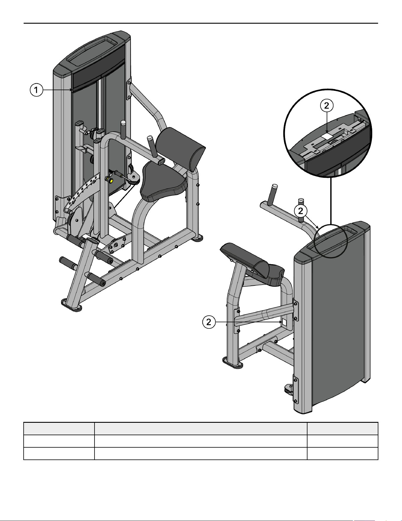
Label Locations
Item Description Qty.
1 Multilingual Label with General Warning 1
2 Serial Number 2
Page 6 of 38

Assembly
Component and Hardware List
Tower Components
Item Description Qty.
1 Tower Frame 1
2 Guide Rod 2
3 Increment Weight Guide Rod 2
4 Rear Shroud 1
5 Label, Weight Stack 1
6 Tube Cap 2
7 Top Cap 1
Tower Hardware Kit
Item Description Qty.
1 Tower Hardware Kit, CI-ABBA 1
2 Hole Plug, 8.7 mm 2
3 Hole Plug, ½" 2
4 Grommet 2
5 Shroud Retainer 14
6 Bushing 4
7 Screw, 8 x ¾" Phillips 2
8 Screw, M10 x 1.5, 55mm 2
9 Nut, M10 x 1.5, Hex Nylock 2
10 Nut, ¼" Nylock 2
11 Washer, Flat ¼" ID 2
12 Washer, Flat 3/8" ID 4
13 Weight Stack Cushion 2
14 Increment Weight Bumper 1
15 Spring 2
16 Guide Rod Housing 2
17 Pulley, 3.5" OD 1
18 Pulley, 4.5" OD 1
Page 7 of 38
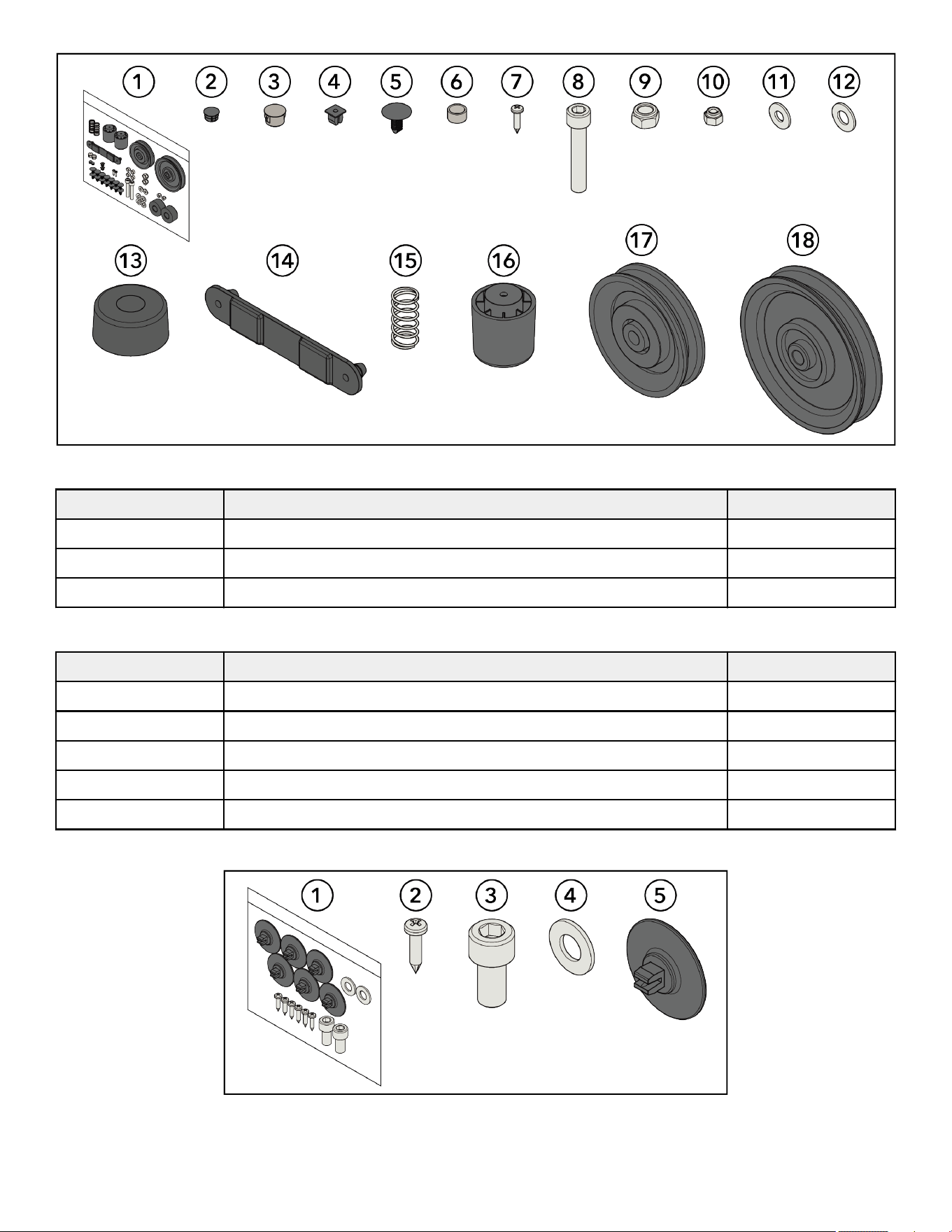
Tower Hardware Kit
Front Shroud Kit Components
Item Description Qty.
1 Front Shroud, Le 1
2 Front Shroud, Right 1
3 Bottom Cap 1
Front Shroud Kit Hardware Kit
Item Description Qty.
1 Front Shroud Hardware Kit 1
2 Screw, M4.2 x 0.7, Phillips 6
3 Screw, M10 x 1.5, 20mm 2
4 Washer, Flat 3/8" 2
5 Grommet, Shroud Retainer 6
Front Shroud Kit Hardware Kit
Page 8 of 38

Components
Item Description Qty.
1 Main Frame Assembly 1
2 Base Frame Assembly 1
3 Cross Brace 1
4 Lower Pulley Assembly 1
5 Pivot Sha 1
6 Input Arm Assembly with Pulleys 1
7 Detent Arm Assembly 1
8 Input Arm Assembly 1
9 Handle Arm Assembly 1
10 Retaining Plate 2
11 Seat Pad 1
12 Lumbar Pad 1
13 Cable 1
14 Front Cap 1
15 Head Plate Assembly 1
16 Increment Weight Assembly 1
17 Multilingual Label Sheet 1
18 Weight Stack
(Weight Plates)
1
(12)
Hardware Kit
Item Description Qty.
1 Hardware Kit, CI-ABBA 1
2 Nut, M10 x 1.5, Hex Nylock 16
3 Nut, M10, Hex Jam 1
4 Nut, M16, Hex Jam 1
5 Washer, Flat 3/8" 41
6 Washer, Fender 3/8" 2
7 Screw, M6, HCS, 50mm 4
8 Screw, M10 x 1.5, 25mm 14
9 Screw, M10 x 1.5, 30mm 8
10 Screw, M10 x 1.5, 35mm 6
11 Screw, M10 x 1.5, 110mm 2
12 Screw, M10 x 1.5, 120mm 6
13 Increment Weight Cap, LBS (7.5) 1
14 Increment Weight Cap, KG (3.75) 1
15 Rod End Bearing 1
Page 9 of 38
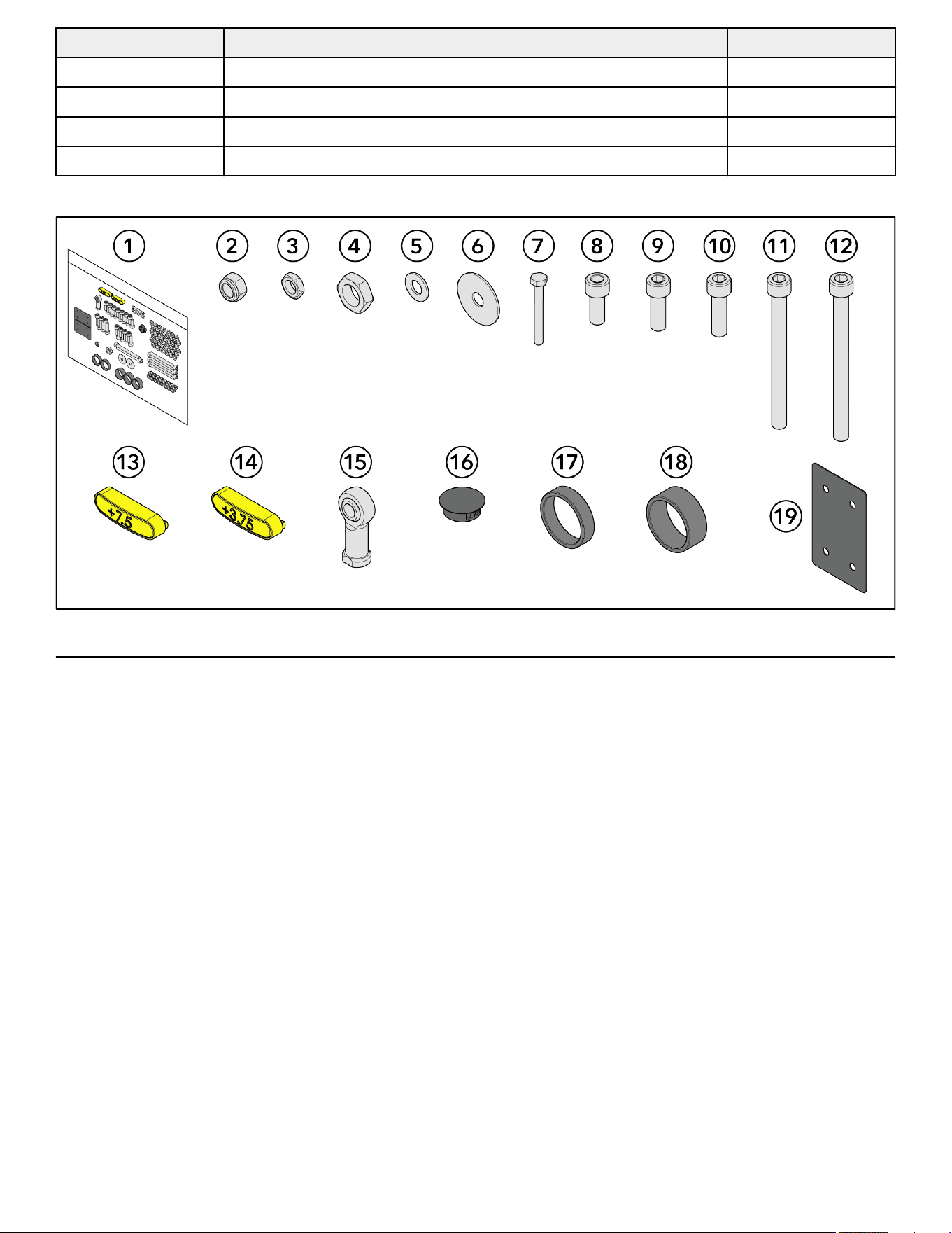
Item Description Qty.
16 Hole Plug, 1" 1
17 Spacer, .403" 2
18 Spacer, .653" 3
19 Shim 2
Hardware Kit
Tools Required
• 7/16" Wrench
• 10 mm Wrench
• 17 mm Wrench
• 7 mm Allen wrench
• 8 mm Allen wrench
• 10 mm Socket wrench
• 10 mm Ratchet wrench
• Torque wrench
• Crescent wrench
• Phillips screwdriver
• Rubber mallet
Page 10 of 38
Assembly Procedure
Two people will be required for this procedure.
TIP: Read and understand all instructions thoroughly before assembling this unit. Check all items carefully. If there is damage, see the
Customer Service section of this manual for proper procedure to return, replace, or reorder parts.
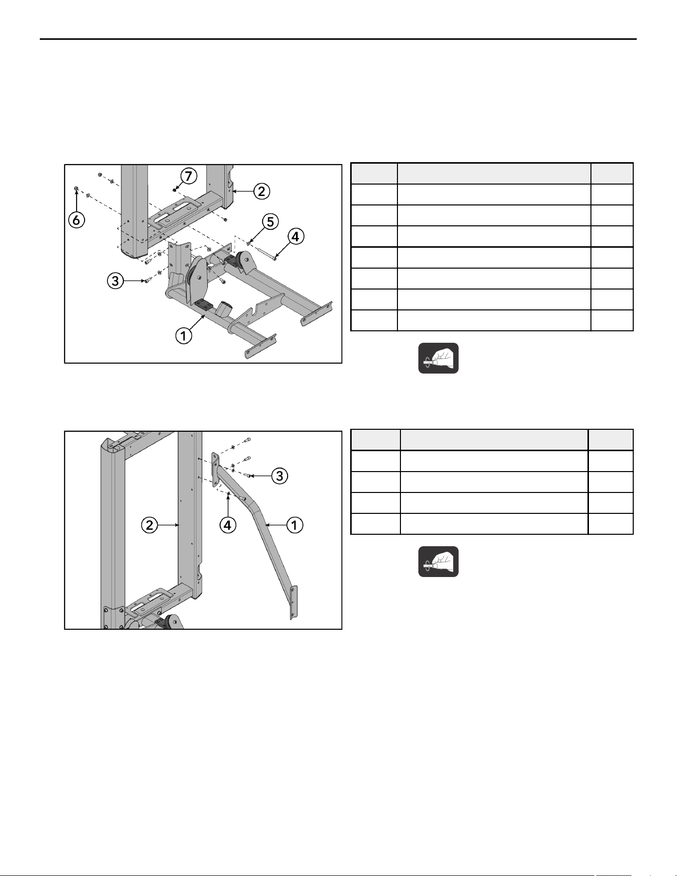
Assemble Frame Components
1. Install screws, washers, and locknuts securing the base frame assembly to the tower frame using an 8mm Allen wrench and a
17mm wrench.
Item Description Qty.
1 Base Frame Assembly 1
2 Tower Frame 1
3 Screw, M10 x 1.5, 25mm 4
4 Screw, M10 x 1.5, 110mm 2
5 Washer, Flat 3/8" 8
6 Nut, M10 x 1.5, Hex Nylock 2
7 Hole Plug, ½" 2
Hand tighten hardware.
2. Install hole plugs to the tower frame.
3. Install screws and washers securing the cross brace to the tower frame using an 8mm Allen wrench.
Item Description Qty.
1 Cross Brace 1
2 Tower Frame 1
3 Screw, M10 x 1.5, 25mm 4
4 Washer, Flat 3/8" 4
Hand tighten hardware.
Page 11 of 38
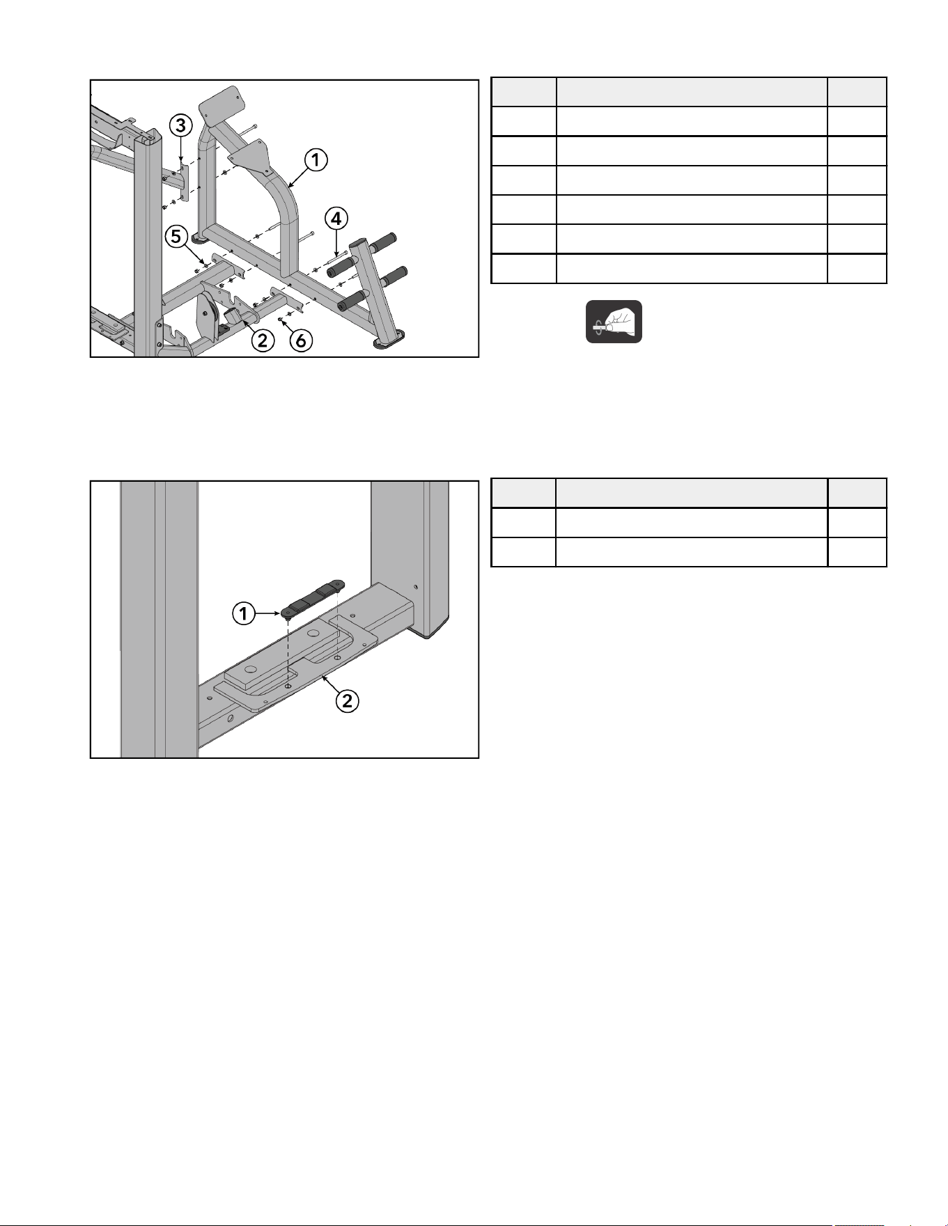
4. Install screws, washers, and locknuts securing the main frame assembly to the base frame assembly and cross brace using an
8mm Allen wrench and a 17mm wrench.
Item Description Qty.
1 Main Frame Assembly 1
2 Base Frame Assembly 1
3 Cross Brace 1
4 Screw, M10 x 1.5, 120mm 6
5 Washer, Flat 3/8" 12
6 Nut, M10 x 1.5, Hex Nylock 6
Hand tighten hardware.
5. Tighten all the hardware to 20-25 -lb (27.1-33.9 Nm).
Assemble Tower
1. Install the increment weight bumper to the bottom plate of the tower frame.
Item Description Qty.
1 Increment Weight Bumper 1
2 Tower Frame 1
Page 12 of 38
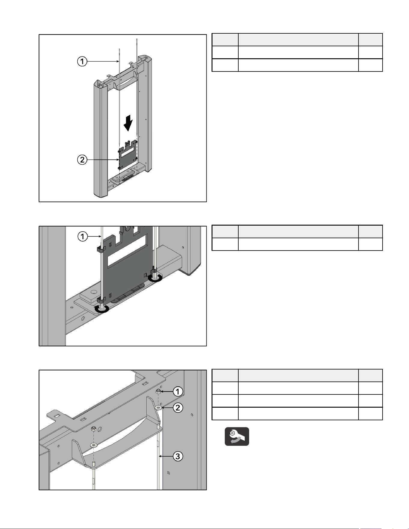
2. Slide increment weight guide rods through the top of the tower frame and down through the clips in the increment weight. Place
increment weight guide rods into holes at the bottom plate of the tower frame.
Item Description Qty.
1 Increment Weight Guide Rod 2
2 Increment Weight 1
3. Thread increment weight guide rods into the bottom plate of the tower frame. Tighten using a crescent wrench.
Item Description Qty.
1 Increment Weight Guide Rod 2
4. Install nuts and washers securing the increment weight guide rods to the top plate of the tower frame using a 7/16" wrench.
Item Description Qty.
1 Nut, ¼" Nylock 2
2 Washer, Flat ¼" ID 2
3 Increment Weight Guide Rod 2
Tighten hardware to 16-20 in-lb (1.8-2.2 Nm).
Page 13 of 38
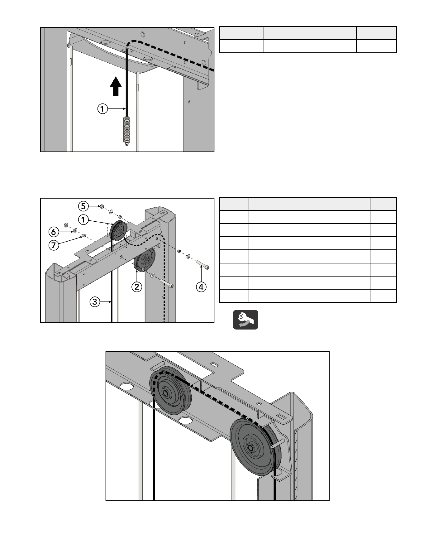
5. Route cable up through the top of the tower frame and down through the side tube of the frame.
Item Description Qty.
1 Cable 1
6. Install screws, washers, spacers, and nuts securing the pulleys to the top of the tower frame using an 8mm Allen wrench and
17mm wrench.
NOTE: Make sure the spacers are centered and inside the tube wall.
Item Description Qty.
1 Pulley, 3.5" OD 1
2 Pulley, 4.5" OD 1
3 Cable 1
4 Screw, M10 x 1.5, 55mm 2
5 Nut, M10 x 1.5, Hex Nylock 2
6 Washer, Flat 3/8" ID 4
7 Bushing 4
Tighten hardware to 14-16 -lb (19-21.7 Nm).
NOTE: Make sure cable is routed over the pulleys and underneath the pins in the tower frame.
7. Flex rear shroud into position inside the tower frame.
Page 14 of 38
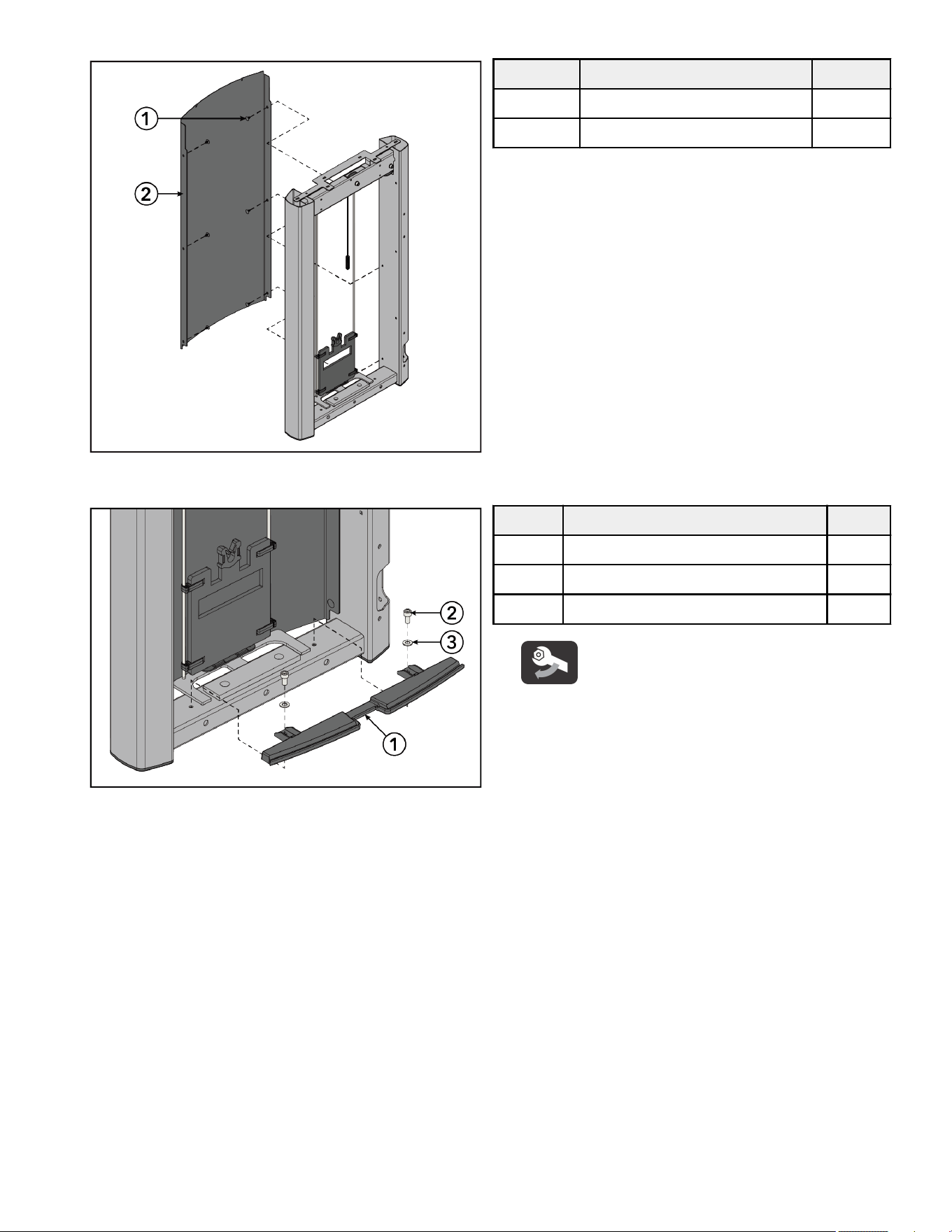
8. Starting at the top, press the shroud retainers into the rear shroud securing it to the tower frame.
Item Description Qty.
1 Shroud Retainer 6
2 Rear Shroud 1
9. Install screws and washers securing the bottom cap to the bottom of the tower frame using an 8mm Allen wrench.
Item Description Qty.
1 Bottom Cap 1
2 Screw, M10 x 1.5, 20mm 2
3 Washer, Flat 3/8" 2
Tighten hardware to 8-10 -lb (10.8-13.5 Nm).
Page 15 of 38
10. Install screws and shroud retainer grommets into the side tubes of the tower frame using a Phillips screwdriver.
Item Description Qty.
1 Grommet, Shroud Retainer 6
2 Screw, M4.2 x 0.7, Phillips 6
Tighten hardware to 10-13 in-lb (1.1-1.5 Nm).
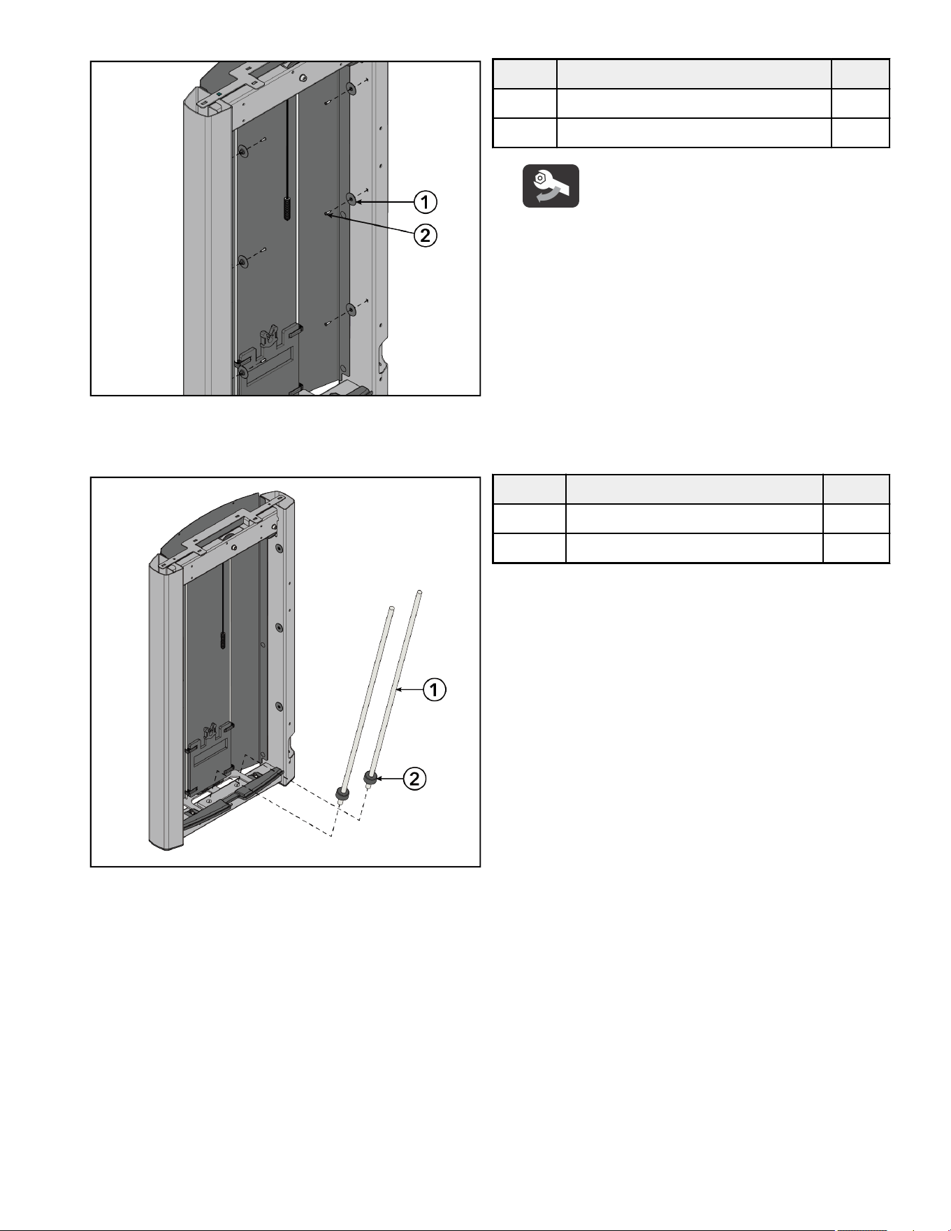
11. Slide weight stack cushions onto the guide rods.
12. Place guide rods with weight stack cushions into the holes at the bottom of the tower frame.
Item Description Qty.
1 Guide Rod 2
2 Weight Stack Cushion 2
Page 16 of 38
13. Lean guide rods outwards and slide weight stack down guide rods onto weight stack cushions. Slide head plate assembly down
guide rods and onto weight stack.
Item Description Qty.
1 Guide Rod Housing 2
2 Spring 2
3 Guide Rod 2
4 Head Plate Assembly 1
5 Weight Stack
(Weight Plates)
1
(12)
14. Tip guide rods back into an upright position in the tower frame. Compress guide rod housings onto the springs and guide rods and
fit up into the top of the tower frame.
Item Description Qty.
1 Guide Rod Housing 2
2 Spring 2
3 Guide Rod 2
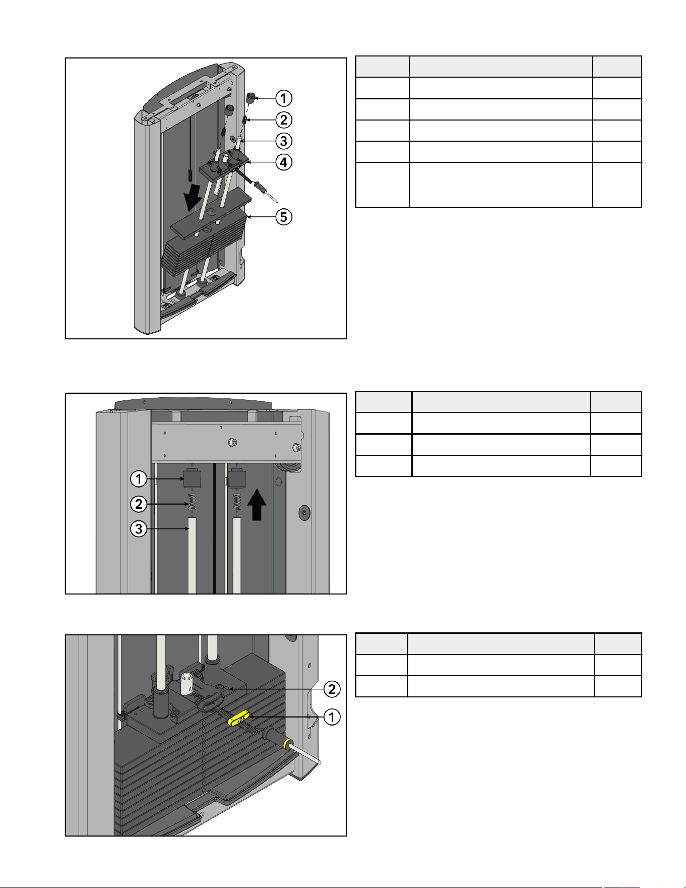
15. Select the LBS (7.5) or KG (3.75) option of the increment weight cap. Press increment weight cap into the head plate assembly.
Item Description Qty.
1 Increment Weight Cap 1
2 Head Plate Assembly 1
Page 17 of 38
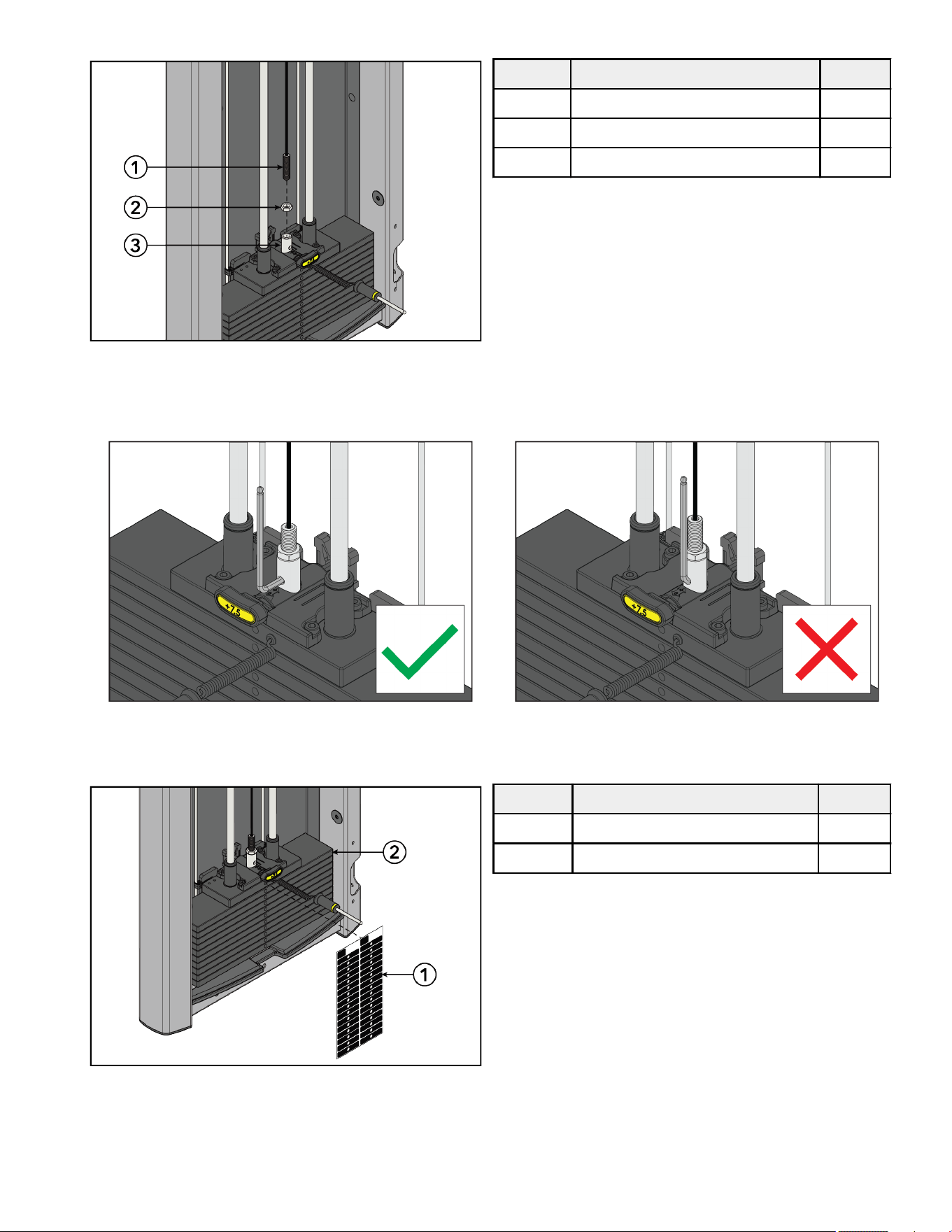
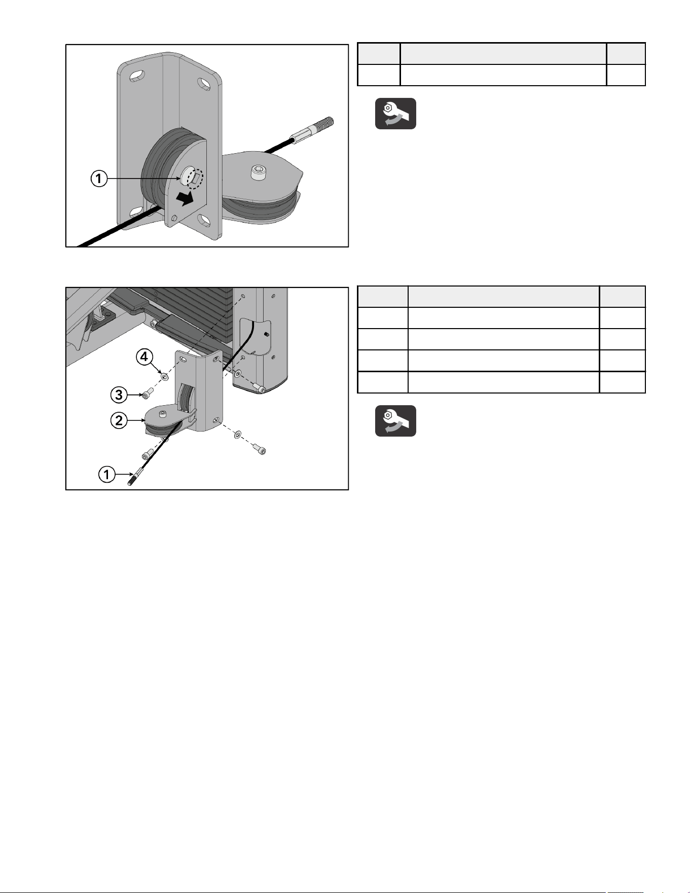
16. Thread cable end through the jam nut and into the head plate bayonet. See Cable Handling Guide for details.
Item Description Qty.
1 Cable 1
2 Nut, M16 Hex Jam 1
3 Head Plate Bayonet 1
NOTE: Check proper thread engagement. To do so, attempt to pass a 7mm Allen wrench through the portal in the head plate
bayonet. If it goes through, more threads are needed to meet the minimum requirement.
Correct Depth: Thread engagement exceeds minimum depth. Incorrect Depth: Thread engagement not deep enough.
17. Select either the LBS or KG weight stack label. Remove backing from label and apply to weight stack.
NOTE: One weight stack label sheet, LBS or KG, is used for both weight stacks.
Item Description Qty.
1 Weight Stack Label 1
2 Weight Stack 1
18. Test the tower assembly.
19. Route cable out through hole at the bottom of tower side tube. Route cable through the lower pulley assembly.
Page 18 of 38
20. Slide the carriage bolt to the end of the slot in the lower pulley assembly using a 17mm wrench.
Item Description Qty.
1 Carriage Bolt, M10 x 1.5, 50mm 1
Tighten hardware to 20-25 -lb (27.1-33.9 Nm).
21. Install screws and washers securing the lower pulley assembly to the tower frame using an 8mm Allen wrench.
Item Description Qty.
1 Cable 1
2 Lower Pulley Assembly 1
3 Screw, M10 x 1.5, 25mm 4
4 Washer, Flat 3/8" 4
Tighten hardware to 20-25 -lb (27.1-33.9 Nm).
Page 19 of 38
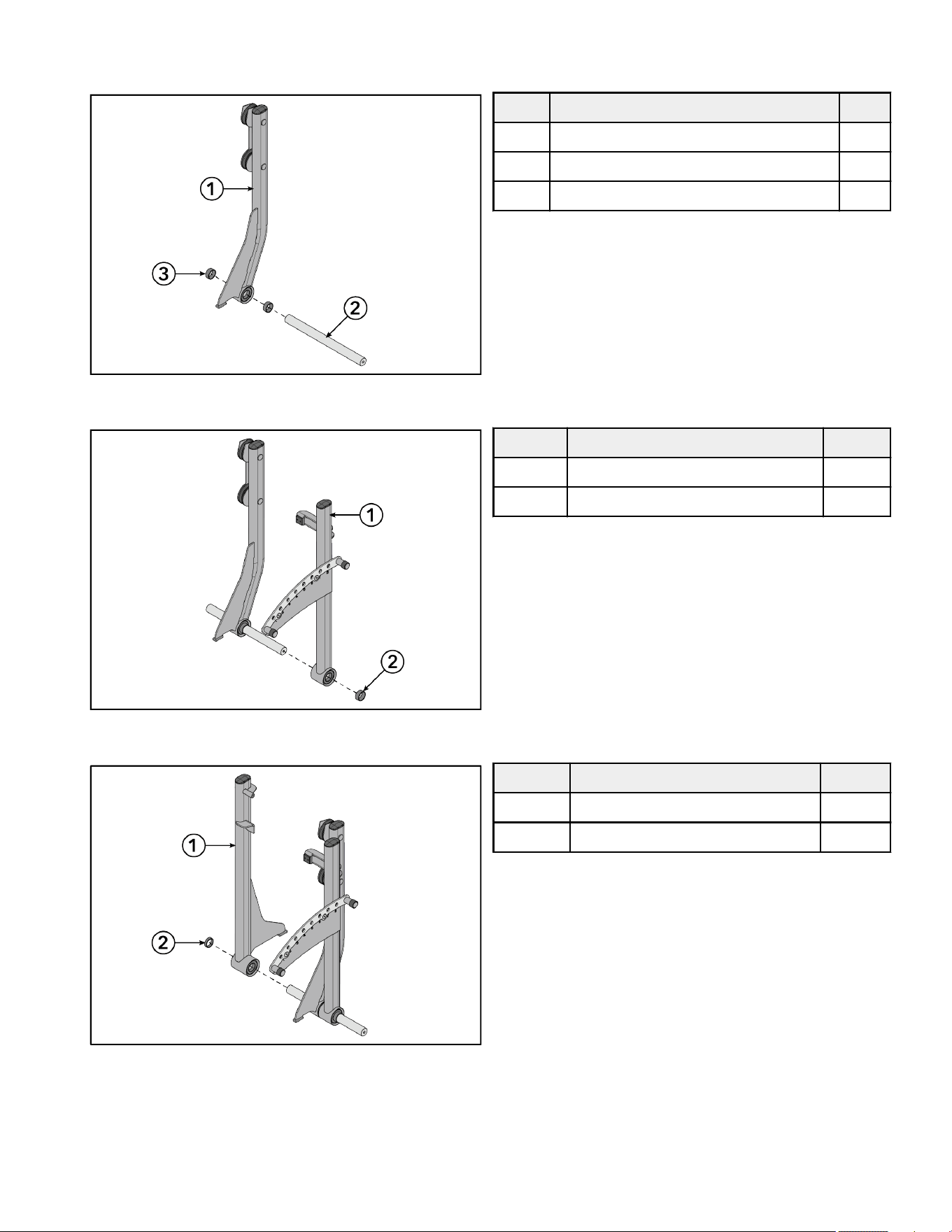
Install Work Arm Assembly
1. Slide .653" spacers and input arm assembly with pulleys onto the pivot sha.
Item Description Qty.
1 Input Arm Assembly with Pulleys 1
2 Pivot Sha 1
3 Spacer, .653" 2
2. Slide detent arm assembly and .653" spacer onto the pivot sha.
Item Description Qty.
1 Detent Arm Assembly 1
2 Spacer, .653" 1
3. Slide input arm assembly and .403" spacer onto the pivot sha.
Item Description Qty.
1 Input Arm Assembly 1
2 Spacer, .403" 1
Page 20 of 38
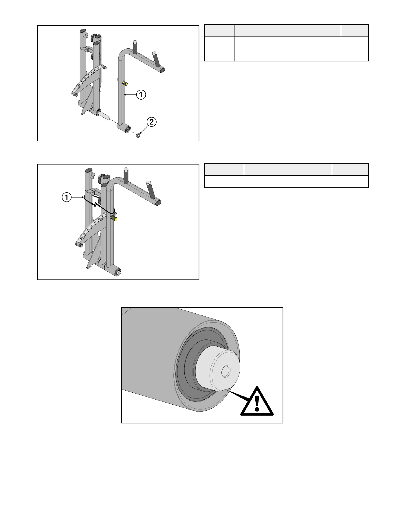
4. Slide handle arm assembly and .403" spacer onto the pivot sha.
Item Description Qty.
1 Handle Arm Assembly 1
2 Spacer, .403" 1
5. Wrap bungee cord around the work arm assembly to hold the arm assemblies together.
Item Description Qty.
1 Bungee Cord 1
NOTE: Position the pivot sha so that the flat side is facing down before lowering the work arm assembly into the base frame
assembly.
Page 21 of 38
6. Place pivot sha in the work arm assembly into the slots on the base frame assembly.
Item Description Qty.
1 Work Arm Assembly 1
2 Base Frame Assembly 1
NOTE: Make sure the pivot sha is fully seated down into both slots before tightening down the bolts, to eliminate the possibility
of adding any unnecessary loose play.
7. Install screws, washers, and locknuts securing the retaining plate to the base frame assembly using an 8mm Allen wrench and a
17mm wrench.
8. Install screw and fender washer securing the retaining plate to the base frame assembly using an 8mm Allen wrench.
Item Description Qty.
1 Retaining Plate 1
2 Base Frame Assembly 1
3 Screw, M10 x 1.5, 25mm 1
4 Screw, M10 x 1.5, 30mm 4
5 Washer, Flat 3/8" 4
6 Washer, Fender 3/8" 1
7 Nut, M10 x 1.5, Hex Nylock 4
Tighten hardware to 14-16 -lb (19-21.7 Nm).
9. Repeat Steps 7 and 8 to install the retaining plate and hardware to the other side of the pivot sha.
Page 22 of 38
Cable Routing
1. Route cable through pulley brackets on the base frame assembly and up through the pulley bracket on the input arm assembly
with pulleys.
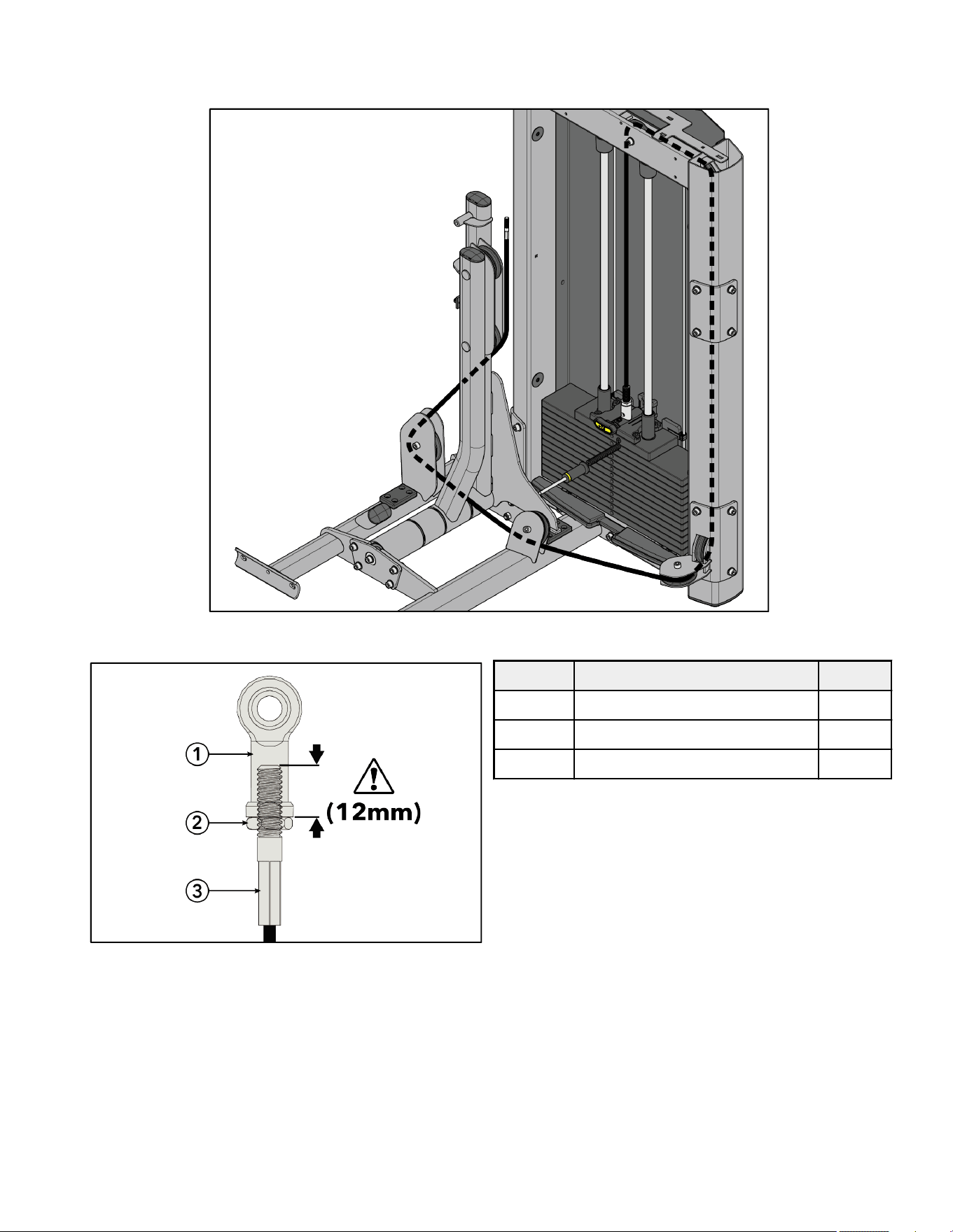
2. Thread cable end through the jam nut and into the rod end bearing a minimum of 12mm.
Item Description Qty.
1 Rod End Bearing 1
2 Nut, M10, Hex Jam 1
3 Cable 1
Page 23 of 38
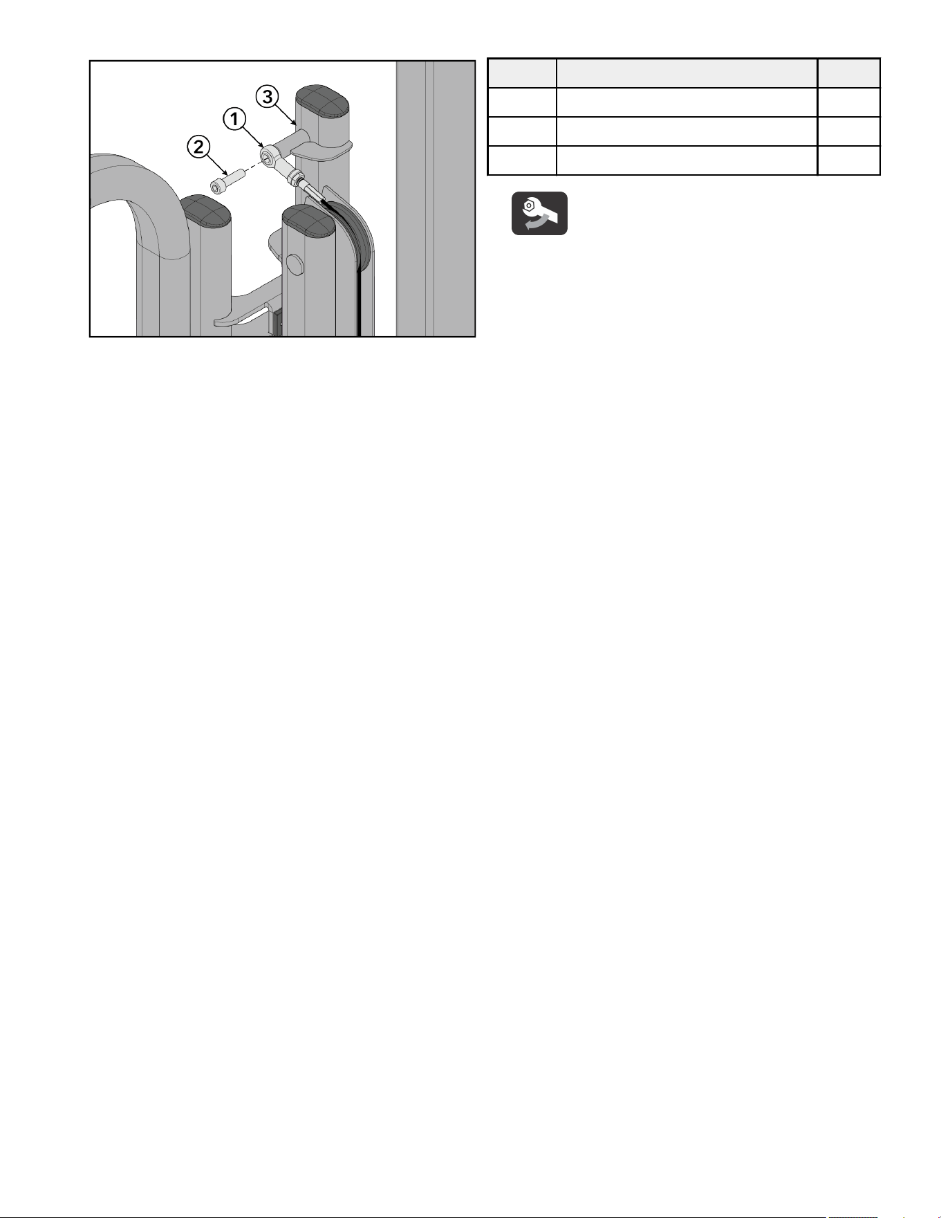
3. Install screw securing the rod end bearing to the input arm assembly using an 8mm Allen wrench.
Item Description Qty.
1 Rod End Bearing 1
2 Screw, M10 x 1.5, 35mm 1
3 Input Arm Assembly 1
Tighten hardware to 20-25 -lb (27.1-33.9 Nm).
Page 24 of 38
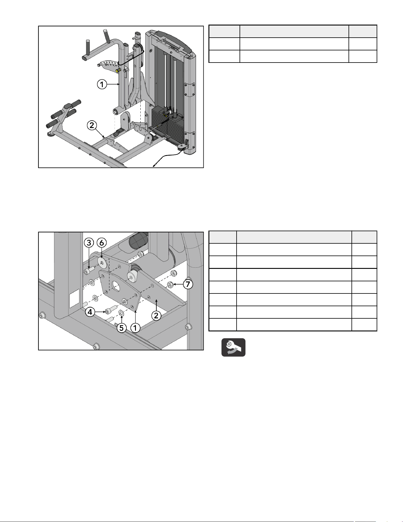
Install/Remove Optional Shims
The objective of installing/removing shims is to get the detent arm assembly as close to vertical as possible, to remove play between
the input arm assembly with pulleys and detent arm assembly, and to remove play between the input arm assembly and detent arm
assembly.
1. To bring the input arm assembly with pulleys and detent arm assembly closer or bring the detent arm assembly towards the front
of the machine:
a. Lean the input arm assembly with pulleys towards the rear of the machine.
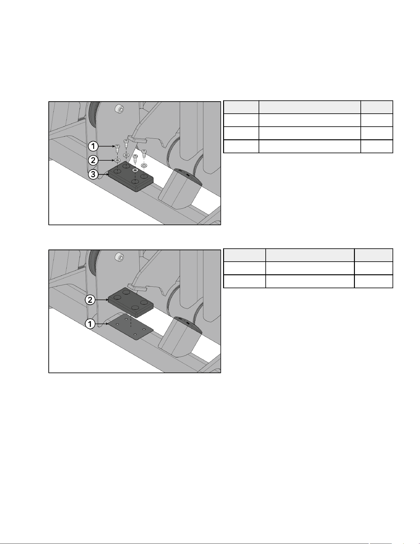
b. Remove screws and washers securing the bumper to the base frame assembly using a Torx screwdriver.
Item Description Qty.
1 Screw, 10-32, TRX 4
2 Washer, M6 4
3 Bumper 1
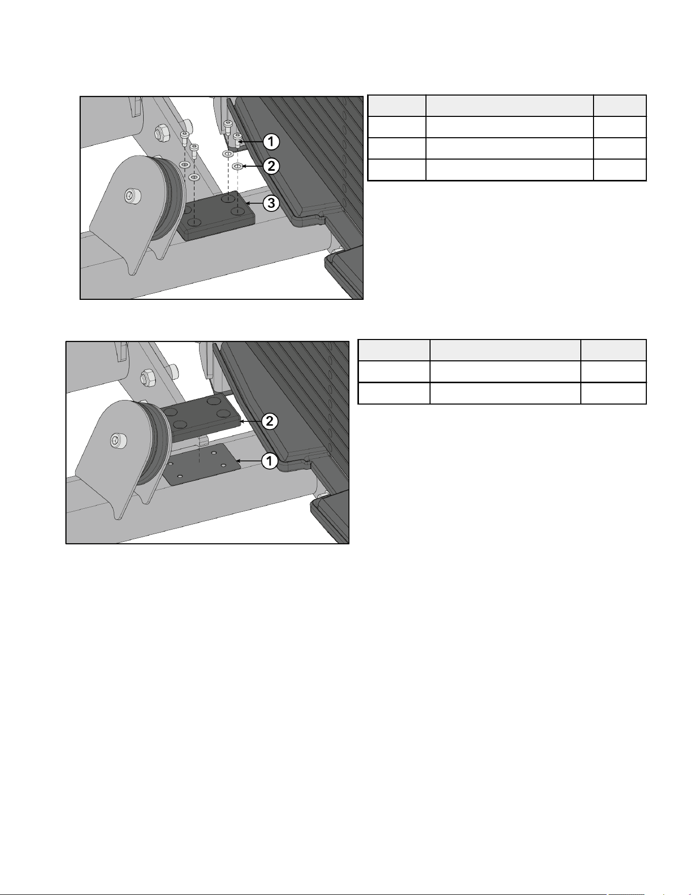
c. Remove shim from under the front bumper.
Item Description Qty.
1 Shim TBD
2 Bumper 1
2. To increase the gap between the input arm assembly with pulleys and detent arm assembly or bring the detent arm assembly
towards the rear of the machine:
a. Install additional shim under the front bumper.
Page 25 of 38
3. To bring the input arm assembly and detent arm assembly closer or bring the detent arm assembly towards the rear of the
machine:
a. Lean the input arm assembly towards the front of the machine.
b. Remove screws and washers securing the bumper to the base frame assembly using a Torx screwdriver.
Item Description Qty.
1 Screw, 10-32, TRX 4
2 Washer, M6 4
3 Bumper 1
c. Remove shim from under the rear bumper.
Item Description Qty.
1 Shim TBD
2 Bumper 1
4. To increase the gap between the input arm assembly and detent arm assembly or bring the detent arm assembly towards the
front of the machine:
a. Install additional shim under the rear bumper.
Page 26 of 38
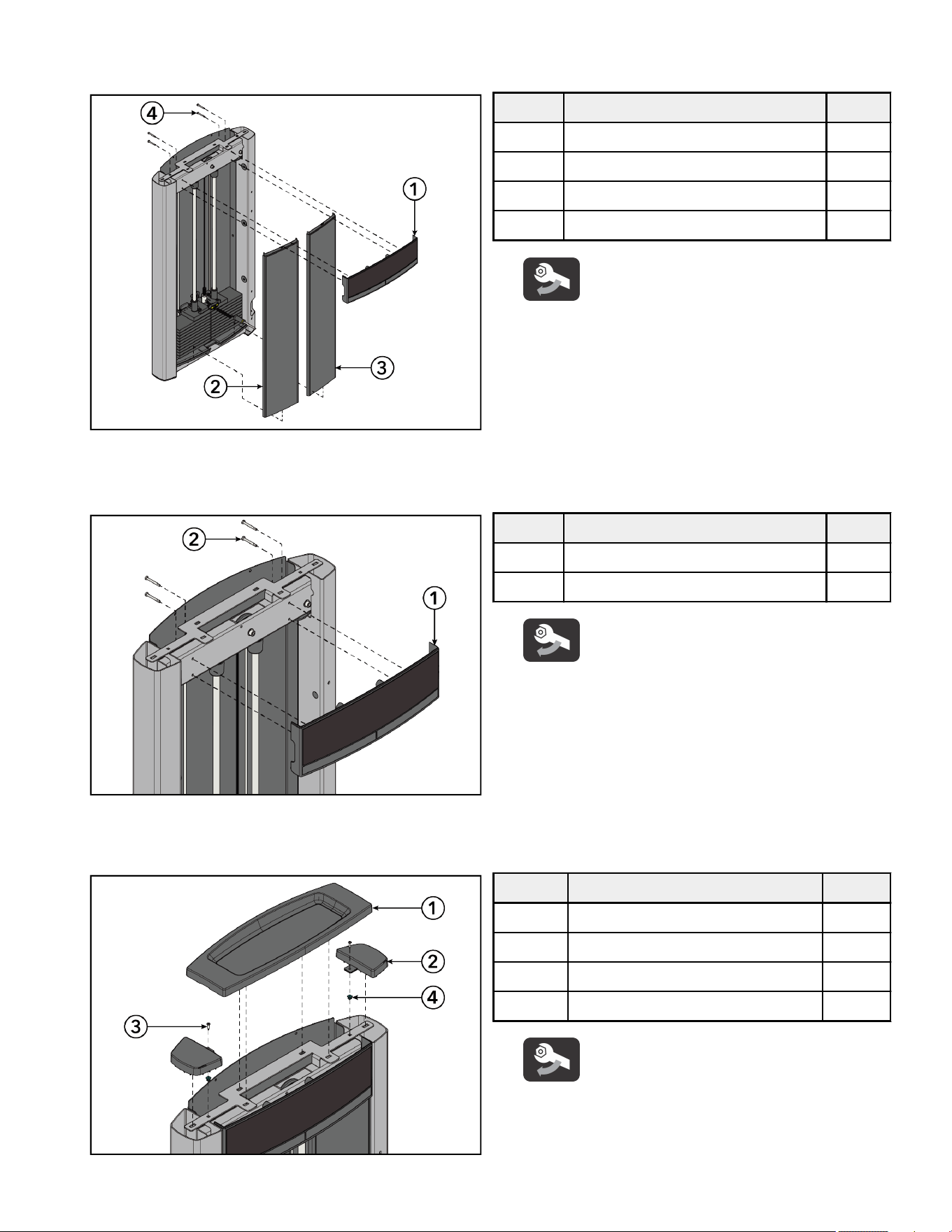
Install Front and Top Caps
1. Set front shrouds into the bottom cap. Install screws securing the front cap to the tower frame using a 10 mm wrench.
Item Description Qty.
1 Front Cap 1
2 Front Shroud, Le 1
3 Front Shroud, Right 1
4 Screw, M6, HCS, 50 mm 4
Tighten hardware to 10-13 in-lb (1.1-1.5 Nm).
2. Install screws securing the front cap to the tower frame using a 10 mm socket wrench and ratchet.
NOTE: Screw heads can be accessed from the top or bottom.
Item Description Qty.
1 Front Cap 1
2 Screw, M6, HCS, 50 mm 4
Tighten hardware to 10-13 in-lb (1.1-1.5 Nm).
3. Press grommets into holes at the top of the tower frame.
4. Install screws securing the tube caps to the tower frame using a Phillips screwdriver.
Item Description Qty.
1 Top Cap 1
2 Tube Cap 2
3 Screw, 8 x ¾" Phillips 2
4 Grommet 2
Tighten hardware to 10-13 in-lb (1.1-1.5 Nm).
Page 27 of 38
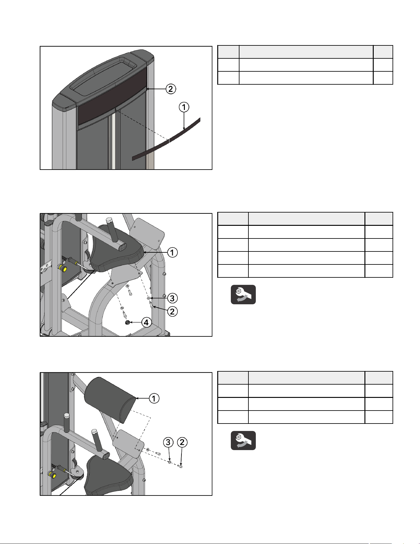
5. Press top cap down into the holes at the top of the tower frame.
6. Select the appropriate language from the multilingual label sheet. Remove backing from multilingual label and apply to the le
and right slots in the front cap.
Item Description Qty.
1 Multilingual Label with General Warning 1
2 Front Cap 1
Install Pads
1. Install screws and washers securing the seat pad to the main frame assembly using an 8mm Allen wrench.
Item Description Qty.
1 Seat Pad 1
2 Screw, M10 x 1.5, 35mm 3
3 Washer, Flat 3/8" 3
4 Hole Plug, 1" 1
Tighten hardware to 40-50 in-lb (4.5-5.6 Nm).
2. Install hole plug to the main frame assembly using a rubber mallet.
3. Install screws and washers securing the lumbar pad to the main frame assembly using an 8mm Allen wrench.
Item Description Qty.
1 Lumbar Pad 1
2 Screw, M10 x 1.5, 35mm 6
3 Washer, Flat 3/8" 6
Tighten hardware to 40-50 in-lb (4.5-5.6 Nm).
Test Unit For Proper Operation
Page 28 of 38
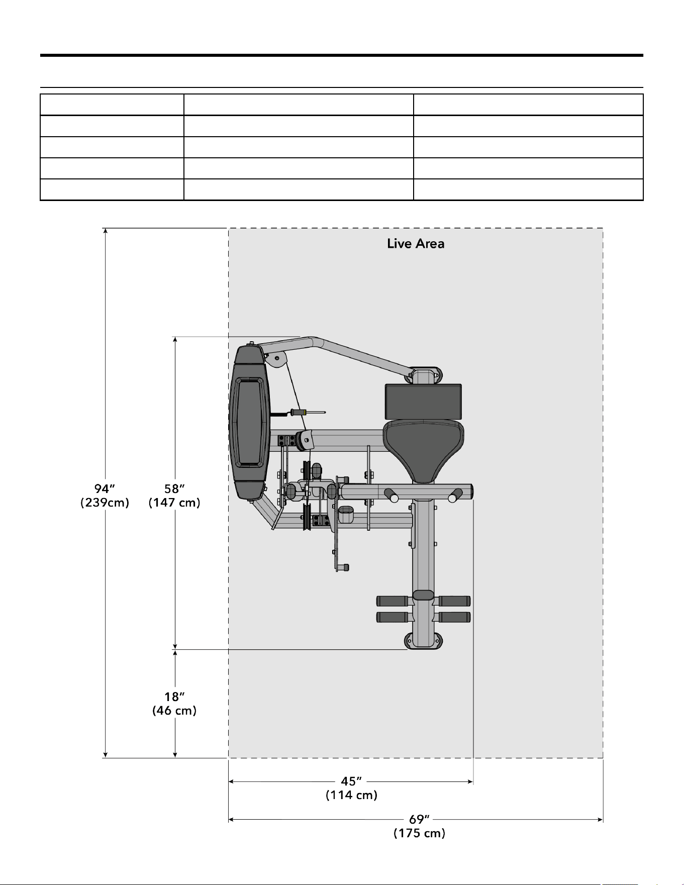
Product Information
Specifications
Machine Weight: 519 lbs. 235 kg.
Size (L x W x H): in. = 58 x 45 x 53 cm = 147 x 114 x 135
Live Area (L x W x H): in. = 94 x 69 x 77 cm = 239 x 175 x 196
Max User Weight: 300 lbs. 136 kg.
Weight Stack: 202.5 lbs. 101.25 kg.
NOTE: Weight Stack weight includes increment weight (7.5 lbs / 3.75 kg).
Page 29 of 38
Cable Handling Guide
Cable Terminations, Tensioning and Wear Guide
Cable Connections with threaded cable ends are required to be installed and maintained following the specifications identified below.
Failure to follow these specifications can lead to the dislocation of the threaded cable during use and can cause serious injury. Along
with securing the threaded cable end and jam nut, it is important to check the entire unit and ensure that all hardware is securely
fastened and not le loose upon completion of cable installation.
WARNING: Use of non certified “techs” note: Service warranties may be void if a non-Cybex-certified technician performs
service work. Replacement of any strength cables should be performed by a Cybex certified technician.
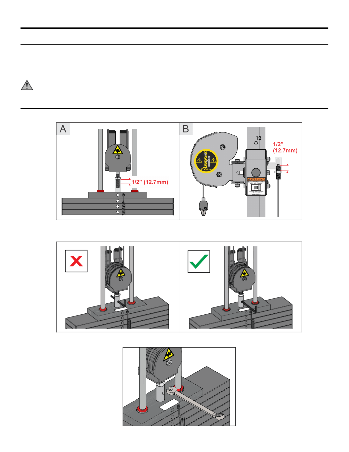
Cable Terminations
1. Cable must be threaded at least ½ inch (12.7mm) into termination points; at headplate (A) and frame/carriage (B).
2. Certain models are now equipped with a bayonet portal to assist checking proper thread engagement. To do so, attempt to pass a
7mm Allen wrench through the portal, if it goes through, more threads are needed to meet the minimum requirement.
3. When proper thread engagement is reached, tighten jam nut to 20-25 FT-LBS (27.2 - 34.0 Nm) using a 24mm wrench.
Page 30 of 38
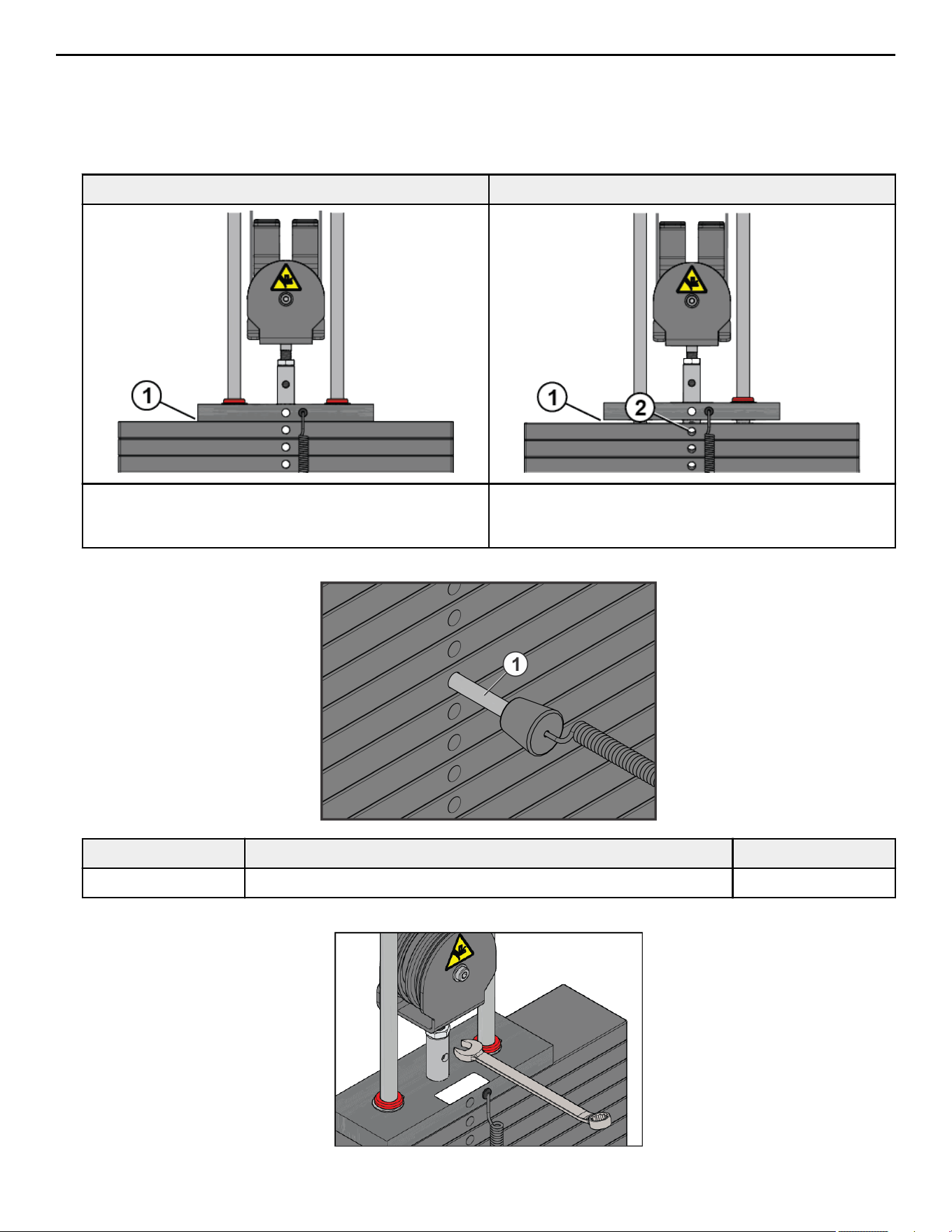
Tensioning Cable
Cable should have enough tension so it stays seated into the pulley but not so tight that it pulls the head plate o the weight plate
below it.
1. If the head plate has lied, loosen the jam nuts at the terminations and loosen the threaded plugs a half turn until the head plate
comes to rest on the weight plate below. Check that the cable's threaded plugs are engaged at least 1/2” (12.7mm) at each
termination point.
SEATED HEAD PLATE SUSPENDED HEAD PLATE
1. No gap 1. Gap
2. Bayonet obstructing weight stack pin
2. Ensure that the weight stack selector pin can fully engage into each weight plate.
Item Description Qty.
1 Weight Stack Selector Pin 1
3. When proper thread engagement is reached, tighten jam nut to 20-25 FT-LBS (27.2 - 34.0 Nm) using a 24mm wrench.
Page 31 of 38
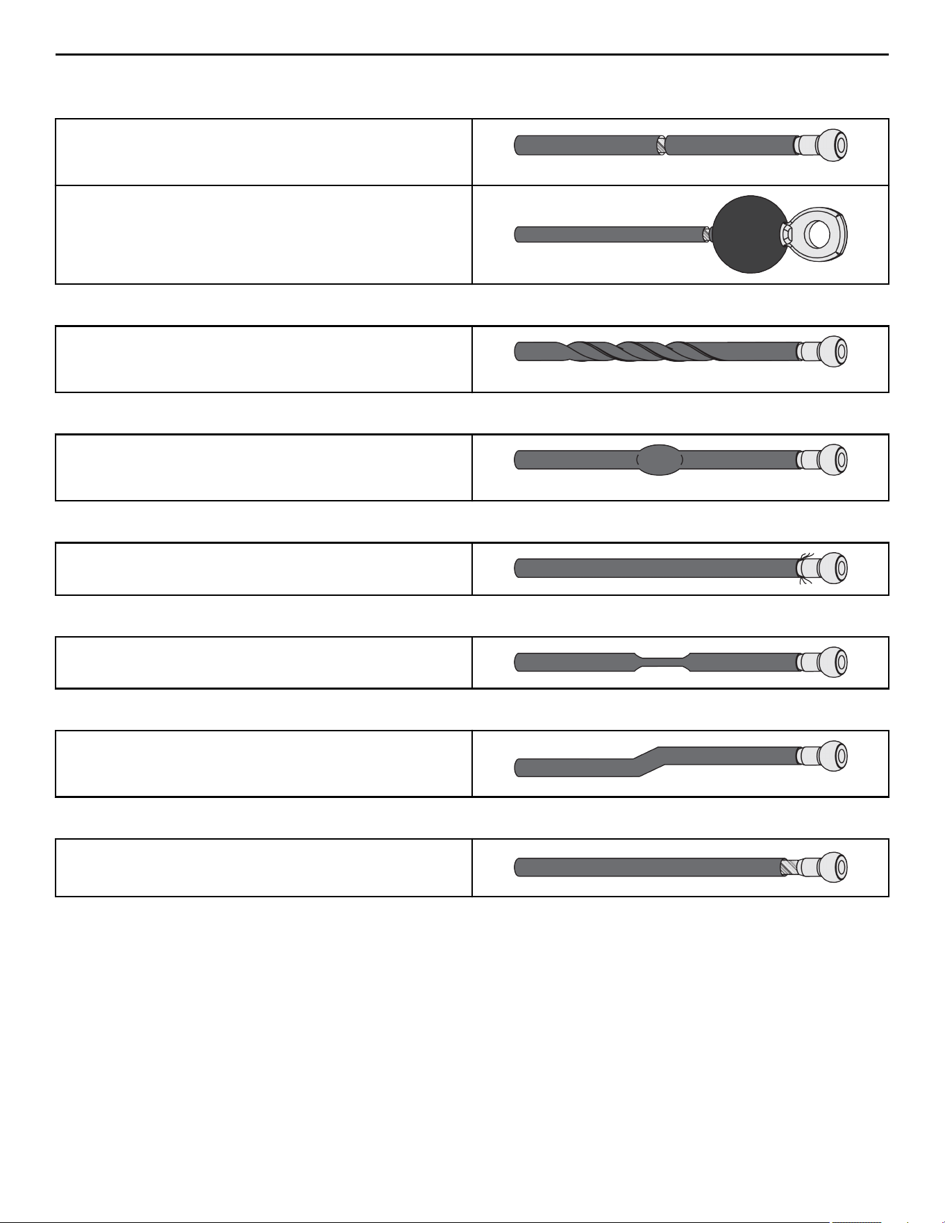
Strength Cable Wear Guide
Replace cable at first sign of any of the following:
FRACTURES:
Casing can crack or fracture under strains during use. Any crack in
the casing merits cable replacement even if no wire rope is
exposed.
Be especially observant for fractures near the components on the
cable assembly - IE. Nylon Ball, Nico Loop, Threaded Plug, etc.
TWISTING/BINDING:
Inspect casing to ensure wire rope is not twisting within its
casing. Any sign of the cable twisting should be replaced
immediately.
BULGING:
Internal wire rope strands can break within and coil causing a
bulge to appear. Cable should retain same outside diameter
throughout.
FRAYED/EXPOSED WIRE ROPE:
Any exposed wire rope protruding through the casing or at either
end.
FLATTENED:
Section of cable is compressed and will not retain its shape
(outside diameter).
PERMANENTLY BENT:
Cable has ‘kink’ and prohibits cable from laying straight. Wire
rope may be unraveling beneath casing and is compromised
warranting replacement.
ENDS SEPARATING:
Watch for component end of cable to pull away from cable
assembly - look for exposed wire rope.
Page 32 of 38

Bolt to Floor Guide
Introduction
Life Fitness Family of Brands designs its products to be stable when used as designed. Because strength training is dynamic, we
cannot predict how users will ultimately use the products in all circumstances. Therefore, Life Fitness Family of Brands recommends
that strength training equipment be secured to a solid, level surface to stabilize and eliminate rocking or tipping over.
Each new unit shipped comes with a multi-language hangtag stating the importance of bolting the unit down as a safety precaution.
It is the facility’s responsibility to adhere to local and regional building codes.
Delivery and Installation Tips
All Anchors
• Fasteners must have minimum embedment in concrete floor, not including screed, regardless of wood/tile/rubber over sub-floor.
(See Anchor Types for maximum sub-floor thickness between unit and concrete to equipment foot must be made of flooring or
other material (i.e. no air gaps)).
• DO NOT reuse fasteners. Static and Dynamic anchors are designed for one-time use only.
• Factor in equipment’s feet height when selecting fastener length.
• Factor in flooring thickness when selecting fastener length.
• It is also recommended to drill an additional 1/2” (12.7 mm) of depth beyond the length of the fastener being used to ensure that
debris does not block the entry of the anchor.
• Minimum concrete compressive strength: 3000 psi (20 N/mm2).
Anchoring
• All anchors must have a minimum embedment into concrete, regardless of wood/tile/rubber/screed over sub-floor.
• Dynamic anchors must have a minimum embedment depth in concrete to ensure maximum security and pull out force. See Anchor
Types for embedment depth minimums.
Building Codes
It is the facility’s responsibility to adhere to local and regional building codes. Please verify with the customer to ensure that they are
aware of this.
Carpeting
If bolted down to carpet flooring, be sure to use a box cutter knife to cut the carpet threads around each foot. This will help avoid the
carpet threads from being wrapped around and pulled by the drill bit.
Competitor Product
The bolt down guidelines and procedures for Cybex products were determined by the company’s Engineering and Installation
Development groups. These guidelines include which anchors to use and positioning of the anchors are required for Cybex product.
• Cybex does not have that level of specification or engineering input for competitive product.
• Cybex installation teams are not permitted to anchor competitor equipment.
Drilling
It is also recommended to drill an additional 1/2” (12.7 mm) of depth beyond the length of the fastener being used to ensure that
debris does not block the entry of the anchor.
• This can be done by marking your drill bit with a piece of tape.
• While it is recommended that a vacuum be used to clean up debris, this will not account for all the debris that will settle at the
bottom of the drilled hole.
Page 33 of 38

Anchor Types
Anchor Subfloor between unit and concrete 0”
to 1/2” (12.7mm) thick
Subfloor between unit and concrete
over 1/2” (12.7mm) thick
Static Imperial KH-EZ 1/4” x 4” KH-EZ 1/4” x 5”
Metric HUS-H 6mm x 120mm HUS-H 6mm x 150mm
Anchor Specifications
Static Anchor Minimum Concrete
Thickness
Minimum Drill Depth in
Concrete
Minimum Concrete
Embedment
Minimum concrete
compressive strength
KH-EZ 1/4” 4-1/8” (105mm) 1/2” (12.7mm) beyond
anchor length
2-1/2” (63.5mm) 3000psi (20 N/mm2)
HUS-H 6mm 3-3/32" (100mm) 25/64" (10mm) beyond
anchor length
2-1/64” (55mm) 3000psi (20 N/mm2)
Pullout Force
Cybex specifies Hilti
™
static and dynamic anchors. According to the anchor manufacturer, the recommended design pullout force (in
tension) for the specified anchors, when properly installed in cracked concrete, is provided in the side table. This table should be used
for reference only; for additional and up-to-date information on the anchor capabilities or the design pullout force in other substrates,
please consult Hilti directly at https://www.us.hilti.com.
Selected Anchor Design Resistance in Tension *
KH-EZ ¼” x 4” 830 lb
HUS-H 6MM x 120MM 3.3 kN
KH-EZ 3/8” x 4” 1535 lb
KH-EZ 3/8” x 5” 1535 lb
HUS-H 8MM x 120MM 3.3 kN
HUS-H 8MM x 150MM 3.3 kN
HSL-3 M 8/40 2000 lb
HST M12 x 115/20 8 kN
HST M12 x 195/200 8 kN
KB-TZ 3/8” x 3-3/4” 1615 lb
* Design strength extracted from the Hilti Anchor Fastening Technology Manual issued September 2014.
Tools Required
WARNING: Adhere to manufacturer’s equipment warnings and guidelines. Follow manufacturer’s instructions for proper
usage.
Static Anchor
• Floor scanner / rebar detector (optional)
• 1” L-shape SDS rotary hammer
• 1/4" x 12" (6mm x 305mm) carbide drill bit (for 1/4” (6mm)
anchors)
• 3/8" x 12" (8mm x 305mm) carbide drill bit (for 3/8” (8mm)
anchors)
• Safety glasses
• Extension cord
• Impact wrench
• Vacuum (for debris)
Page 34 of 38
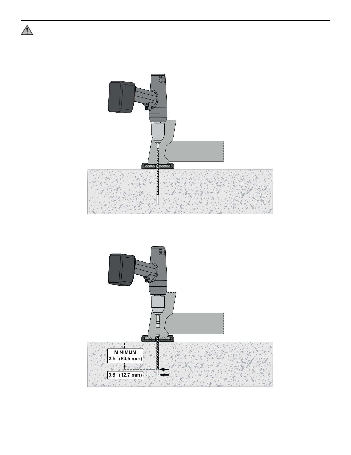
Static Anchor Procedure
CAUTION: If it is possible that the length of your bolt will not provide the minimum requirement of 2.5” (63.5mm) of
engagement, a longer anchor should be used.
1. Place unit into position to be mounted and cycle unit to set stance.
2. Each foot must get at least one static fastener.
3. Wearing protective glasses, drill down into the flooring to the required depth as perpendicular as possible, ensuring that the foot
thickness is being accounted for; refer to Anchor Selection and Foot Dimensions.
4. Insert fastener and tighten to 18 Foot-Pounds (24Nm) for 1/4” (6mm) anchor or 40 Foot-Pounds (54Nm) for 3/8” (8mm) anchor.
NOTE: If the legs/frame do not contact the mounting surface DO NOT pull down with the fastener or anchor. Loosen frame
hardware and re-tighten to allow machine to align.
Page 35 of 38
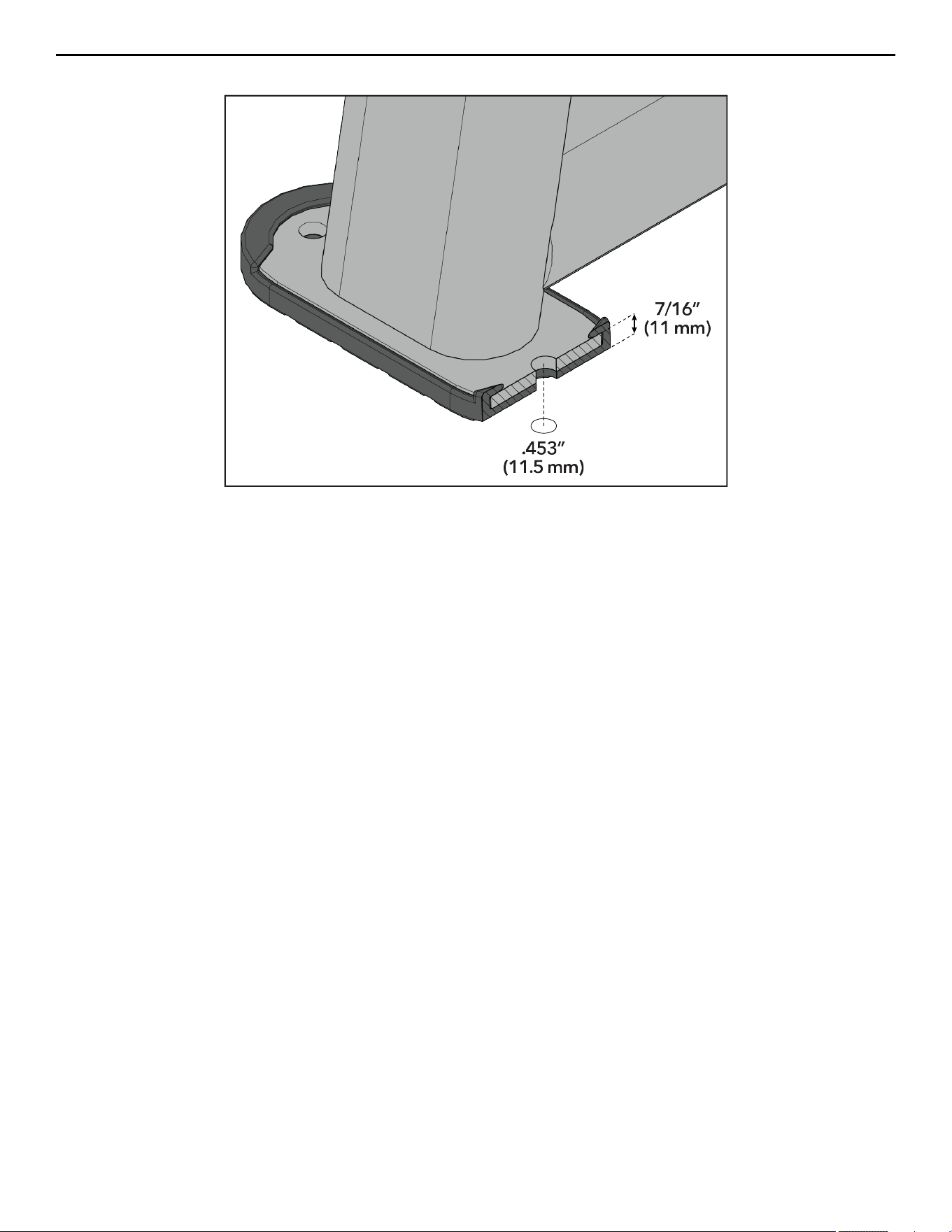
Foot Dimensions
Use below image to determine foot specifications.
Page 36 of 38


Columbia Center III - 9525 Bryn Mawr Ave, Rosemont, IL 60018 • 800-351-3737 • 847-288-3700 • FAX 800-216-8893
www.cybexintl.com