
INSTALLATION GUIDE / USER GUIDE
GUIDE D’INSTALLATION / GUIDE D’UTILISATION
US CA
PROFESSIONAL RANGE HOOD
HCB0-6, HCB6-6, HCB6-12, HCB48-12
HC6 (Shell) & HC48 (Shell) models
HOTTE PROFESSIONNELLE
Modèles HCB0-6, HCB6-6, HCB6-12, HCB48-12
HC6 (Coque) et HC48 (Coque)

English Page 1 – 29
Français
Page 31 – 59

1
CONTENTS
IMPORTANT!
SAVE THESE INSTRUCTIONS
The models shown in this user guide may
not be available in all markets and are
subject to change at any time. For current
details about model and specification
availability in your country, please go to
our website fisherpaykel.com or contact
your local Fisher & Paykel dealer.
Registration
Register your product with us so we can
provide you with the best service possible.
To register your product visit our website:
fisherpaykel.com
EN
Introduction 3
Safety and warnings 4
Product information 6
Installation preparation 8
Installation instructions 16
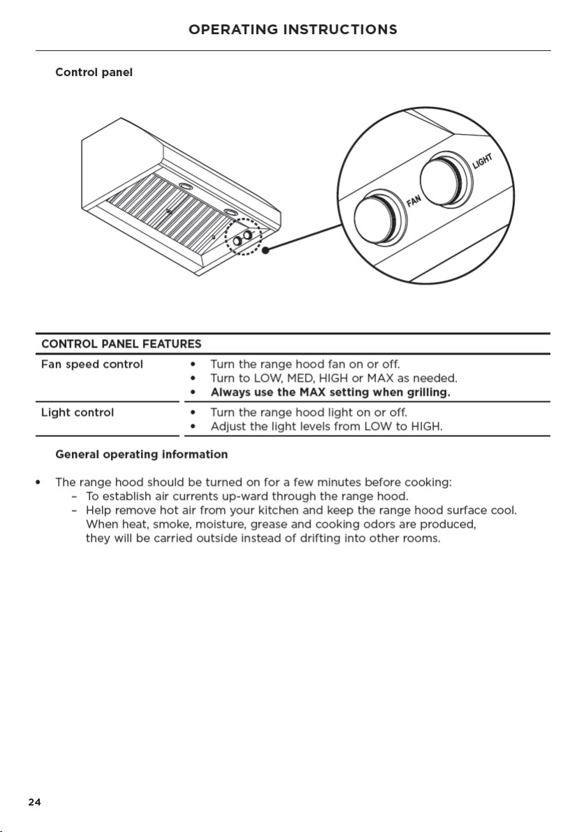
Operating instructions 24
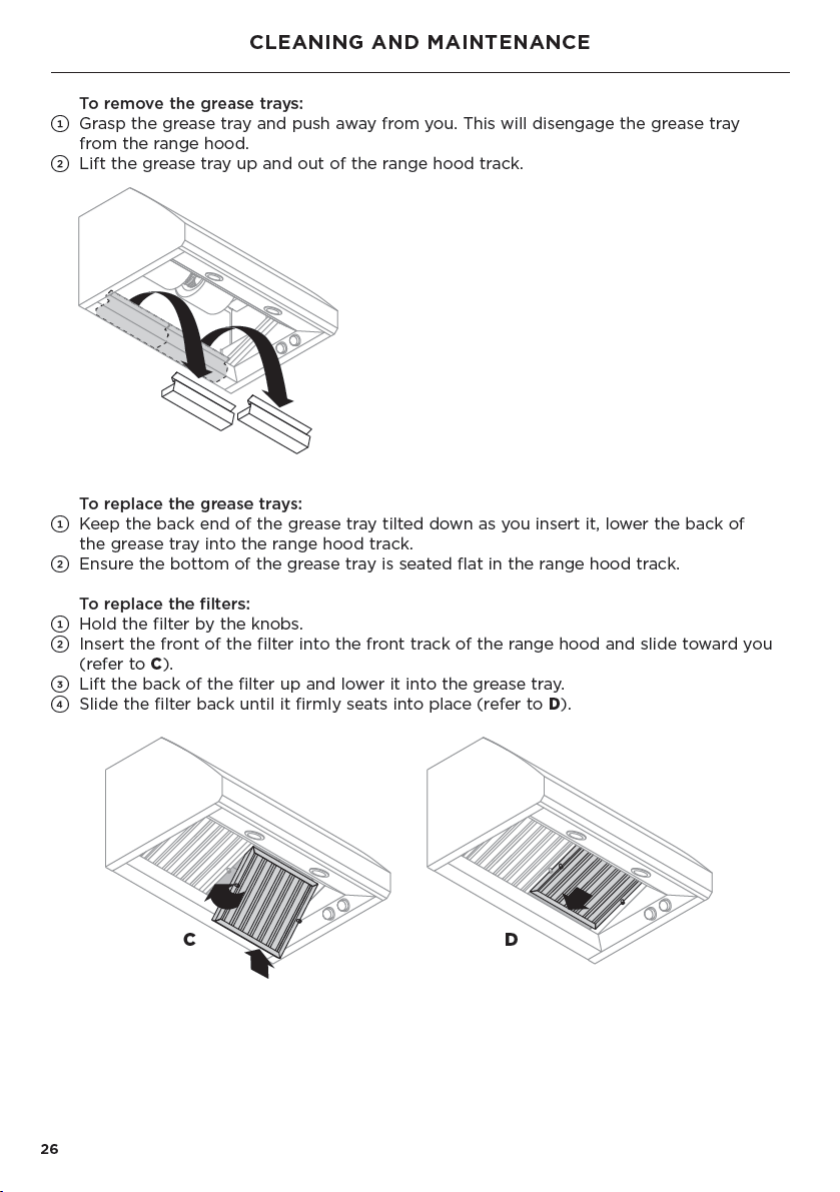
Cleaning and maintenance 25
Maintenance 27
Parts and accessories 28
Service and warranty 29


3
INTRODUCTION
Welcome to the family of Fisher & Paykel appliances. Our team has spent thousands
ofhours designing, engineering and testing it to make sure you get the perfect
productfor your home. For more information visit our website or for further support,
contact ourcustomer care team.
EN

5
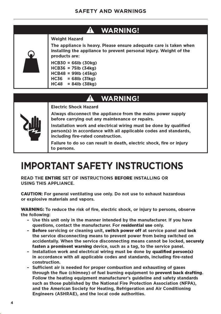
SAFETY AND WARNINGS
– When cutting or drilling into wall or ceiling, do not damage electrical wiring
andother hidden utilities.
– Ducted fans must always be vented to the outdoors.
– This unit must be grounded.
CAUTION: To reduce the risk of fire and to properly exhaust air, be sure to duct air
outside. Do not vent exhaust air into spaces within walls or ceilings or into attics,
crawl spaces, or garages.
WARNING: To reduce the risk of fire, use only metal ductwork.
WARNING: To reduce the risk of fire or electric shock, do not use this fan with
any solid-state speed control device.
WARNING: To reduce the risk of a range top grease fire:
– Never leave surface units unattended at high settings. Boilovers cause smoking
and greasy spillovers that may ignite.
– Heat oils slowly on low or medium settings.
– Always turn hood ON when cooking at high heat or when flambéing food
(ieCrepes Suzette, Cherries Jubilee, Peppercorn Beef Flambé)
– Clean ventilating fans frequently. Grease should not be allowed to accumulate
on fan or filter.
– Use proper pan size. Always use cookware appropriate for the size of the
surfaceelement.
WARNING: To reduce the risk of injury to persons in the event of a range top grease
fire, observe the following*:
– Smother flames with a close-fitting lid, cookie sheet, or metal tray, then
turn offthe burner. Be careful to prevent burns. If the flames do not go out
immediately, evacuate and call the fire department.
– Never pick up a flaming pan — you may be burned.
– Do not use water, including wet dishcloths or towels — a violent steam
explosionwill result.
– Use an extinguisher only if:
– You know you have a Class ABC extinguisher, and you already know
howto operate it.
– The fire is small and contained in the area where it started.
– The fire department is being called.
– You can fight the fire with your back to an exit.
WARNING: All wall and floor openings where the range hood is installed must be sealed.
READ AND SAVE THESE INSTRUCTIONS
*
Based on “Kitchen Firesafety Tips” published by NFPA.
EN
6
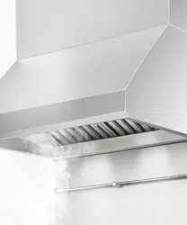
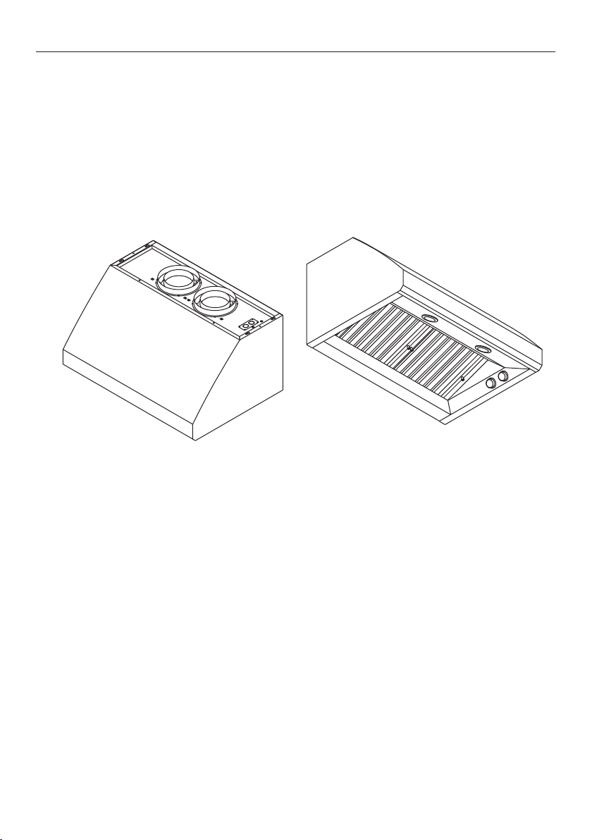
PRODUCT INFORMATION
General information
Please read this manual carefully, and keep it after installation as it will help answer
questions that may arise as you use your new Fisher & Paykel range hood.
Keep all packing material (box, pallet, straps) until the unit has been inspected.
Inspect the product to check there is no shipping damage. If any damage is detected
contact the dealer or retailer you bought the product from to report the damage.
Fisher&Paykel is not responsible for shipping damage.
WARNING!
For residential use only.
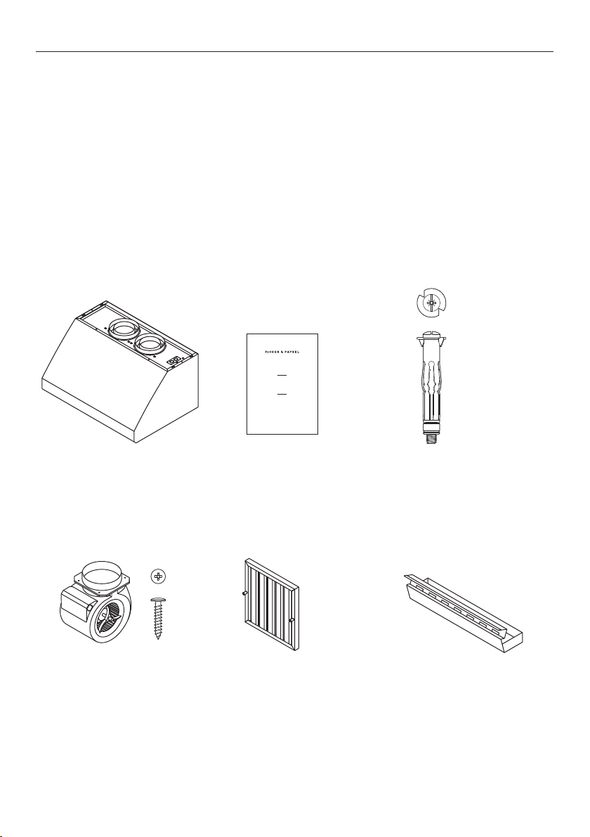
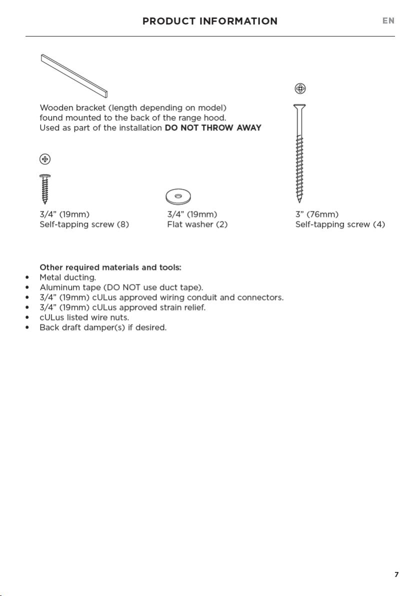
Parts included with your range hood:
User guide (1)
I STA LAT ON GUIDE USER GU DE
UIDE D NSTA LAT ON / GU DE D’ TI IS TION
US CA
PROFESSIONAL RANGE HOOD
H B30 6 HC 36 6 HC 36 12 HCB48 2
HC36 Sh l ) & HC48 ( he ) mode s
HOTTE PROFESSIONNELLE
Mod l s HCB30 6 HCB36 6 CB36 12 HCB 8 2
HC36 ( oqu ) et HC 8 Coq e)
Internal blower, including
3/4” (19mm) screws (4)
●
HCB30-6 (1)
●
HCB36-6 (1)
●
HCB36-12 (2)
●
HCB48-12 (2)
●
HC36/48 (0)
Filters
●
HCB30 (2)
●
HCB36/HC36 (2)
●
HCB48/HC48 (3)
Grease trays
●
HCB30 (2)
●
HCB36/HC36 (2)
●
HCB48/HC48 (3)
Range hood with light
bulbs and 8” (203mm)
duct connection rings
installed (1)
Wall plug (2)
Po
Wa lug
e f tap ng Screw

9
INSTALLATION PREPARATION
HCB30-6 HCB36-6 HCB36-12
HC36
HCB48-12
HC48
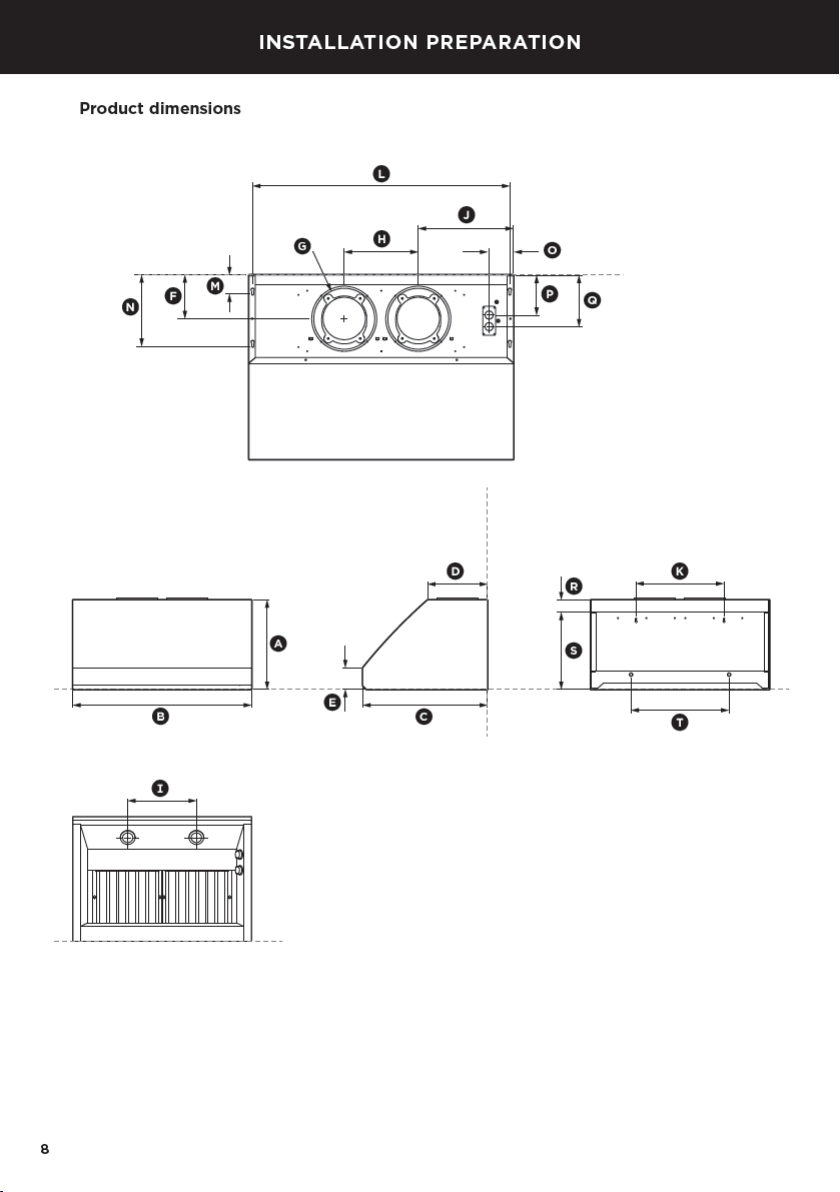
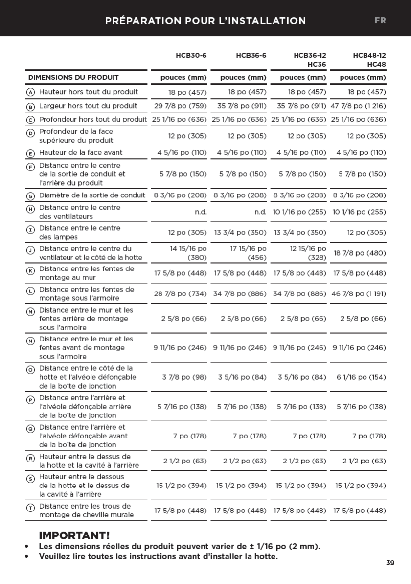
PRODUCT DIMENSIONS inches (mm) inches (mm) inches (mm) inches (mm)
A
Overall height of product 18” (457) 18” (457) 18” (457) 18” (457)
B
Overall width of product 297/8” (759) 357/8” (911) 357/8” (911) 477/8” (1216)
C
Overall depth of product 251/16” (636) 251/16” (636) 251/16” (636) 251/16” (636)
D
Depth of top face of product 12” (305) 12” (305) 12” (305) 12” (305)
E
Height of front face 45/16” (110) 45/16” (110) 45/16” (110) 45/16” (110)
F
Distance from center of ducting
outlet to back of product
5 7/8” (150) 5 7/8” (150) 5 7/8” (150) 5 7/8” (150)
G
Diameter of ducting outlet 83/16” (208) 83/16” (208) 83/16” (208) 83/16” (208)
H
Distance between center
ofblowers
N/A N/A 101/16” (255) 101/16” (255)
I
Distance between center
oflights
12” (305) 133/4” (350) 133/4” (350) 12” (305)
J
Distance between center of
blower to side of range hood
1415/16” (380) 1715/16” (456) 1215/16” (328) 187/8” (480)
K
Distance between wall
mounting slots
175/8” (448) 175/8” (448) 175/8” (448) 175/8” (448)
L
Distance between under
cabinet mounting slots
287/8” (734) 347/8” (886) 347/8” (886) 467/8” (1191)
M
Distance from wall to rear
under cabinet mounting slots
25/8” (66) 25/8” (66) 25/8” (66) 25/8” (66)
N
Distance from wall to front
under cabinet mounting slots
911/16” (246) 911/16” (246) 911/16” (246) 911/16” (246)
O
Dimension from side of
range hood to junction box
knockout
3 7/8” (98) 35/16” (84) 35/16” (84) 61/16” (154)
P
Dimension from back to rear
junction box knockout
57/16” (138) 57/16” (138) 57/16” (138) 57/16” (138)
Q
Dimension from back to front
junction box knockout
7” (178) 7” (178) 7” (178) 7” (178)
R
Height from top of range
hood to recess on back
2 1/2” (63) 2 1/2” (63) 2 1/2” (63) 2 1/2” (63)
S
Height from bottom of range
hood to top of recess on back
15 1/2” (394) 15 1/2” (394) 15 1/2” (394) 15 1/2” (394)
T
Distance between wall plug
mounting holes.
175/8” (448) 175/8” (448) 175/8” (448) 175/8” (448)
IMPORTANT!
●
Actual product dimensions may vary by ± 1/16”(2mm).
●
Please read the entire instructions before installing the range hood.
EN

11
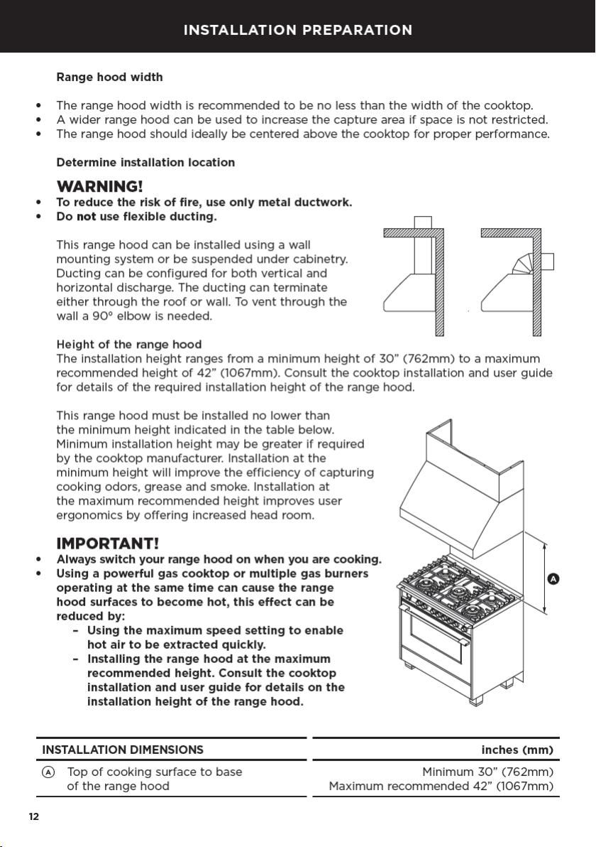
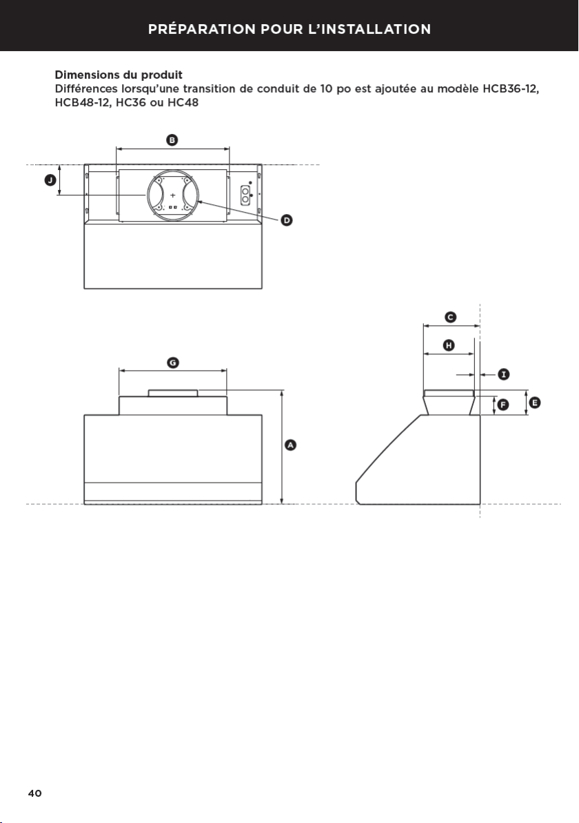
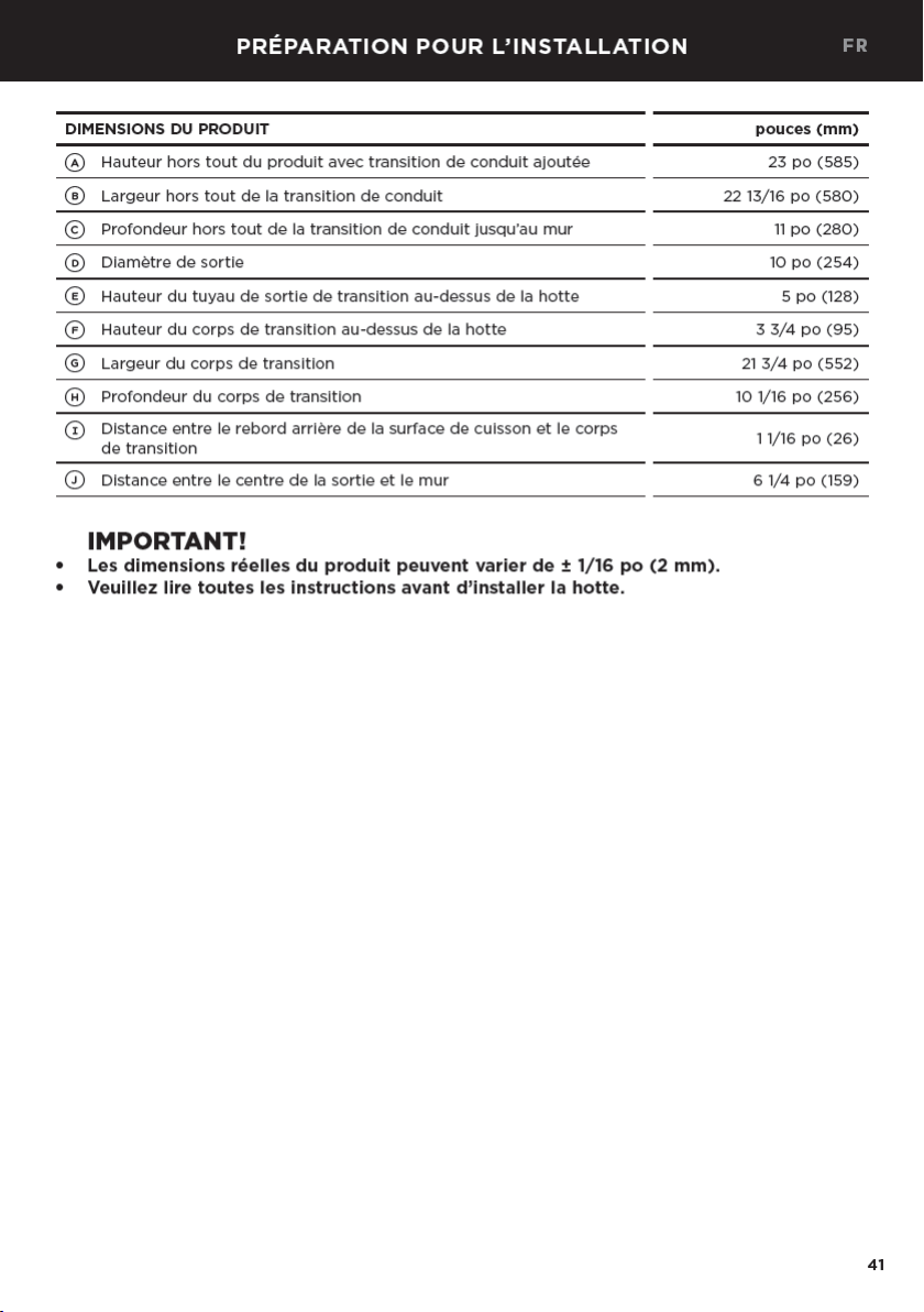
INSTALLATION PREPARATION
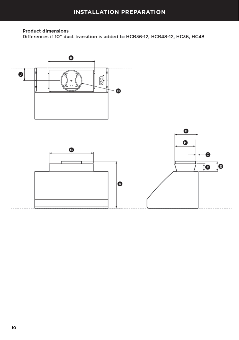
PRODUCT DIMENSIONS inches (mm)
A
Overall height of product with ducting transition added 23” (585)
B
Overall width of ducting transition 22 13/16” (580)
C
Overall depth of ducting transition to wall 11” (280)
D
Outlet diameter 10” (254)
E
Height of transition outlet pipe above range hood 5” (128)
F
Height of transition body above range hood 3 3/4” (95)
G
Width of transition body 21 3/4” (552)
H
Depth of transition body 10 1/16” (256)
I
Distance from back edge of cooktop to transition body 1 1/16” (26)
J
Distance from centre of outlet to wall 6 1/4” (159)
IMPORTANT!
●
Actual product dimensions may vary by ± 1/16”(2mm).
●
Please read the entire instructions before installing the range hood.
EN

15
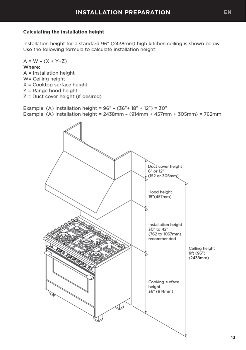
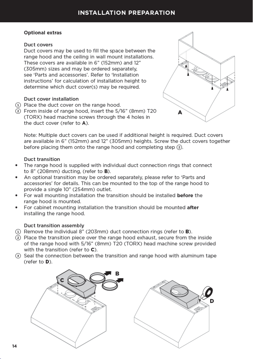
INSTALLATION PREPARATION
Infra-red heat lamp and panel kit
If an optional infra-red heat lamp kit was purchased for installation with the range hood,
assemble the kit to the range hood prior to installation. See instructions supplied with
the kit for assembly to your range hood.
WARNING!
To avoid any electrical shock the installation of the infra-red heat lamp and panel kit
should be done by a qualified electrician and before starting the installation of the
range hood.
EN

16
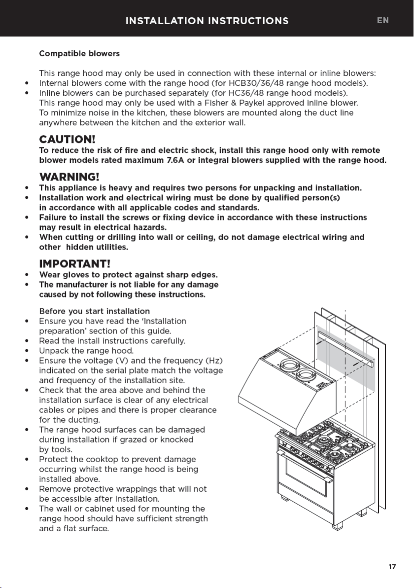
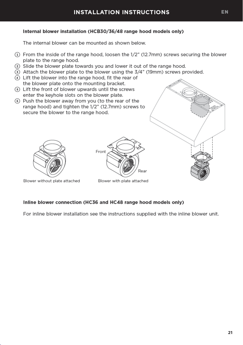
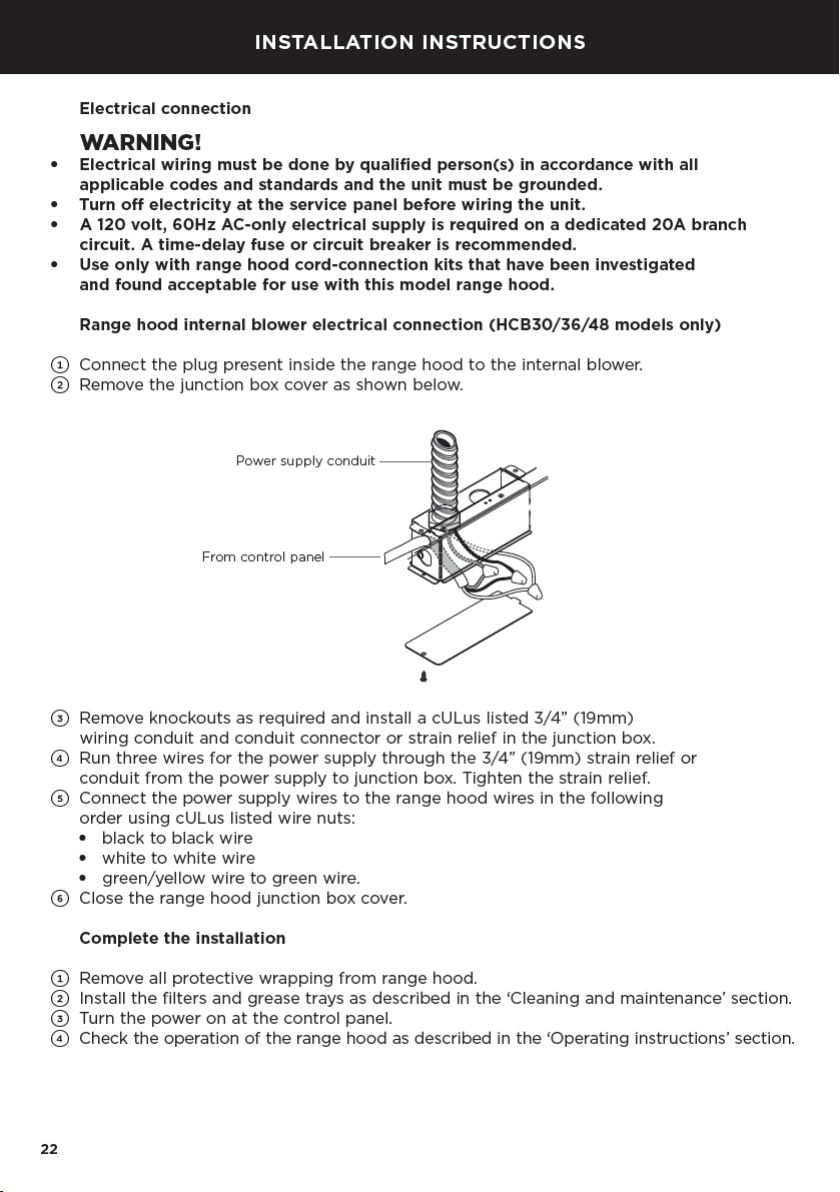
INSTALLATION INSTRUCTIONS
Electrical requirements
WARNING!
●
Installation and electrical wiring must be done by qualified person(s) in accordance
with all applicable codes and standards.
●
This unit must be grounded/earthed.
●
This range hood must be connected with copper wire only.
●
A 120 volt, 60Hz AC-only electrical supply is required on a dedicated 20A branch circuit.
A time-delay fuse or circuit breaker is recommended.
●
Wire sizes must conform to the requirements of the National Electrical Code,
ANSI/NFPA 70-latest edition, and all local codes and ordinances.
●
Wire size and connections must conform to the rating of this appliance.
●
This appliance should be connected directly to the fuse disconnect (or circuit breaker)
through flexible, armored or non-metallic sheathed copper cable. Allow some slack
inthe cable so the appliance can be moved if servicing is required.
●
A cULus listed strain relief or 3/4” (19mm) conduit connector must be provided at
eachend of the power supply cable (at the appliance and at the junction box).
WARNING!
To reduce the risk of fire or electric shock, do not use this fan with any solid-state
speed control device.
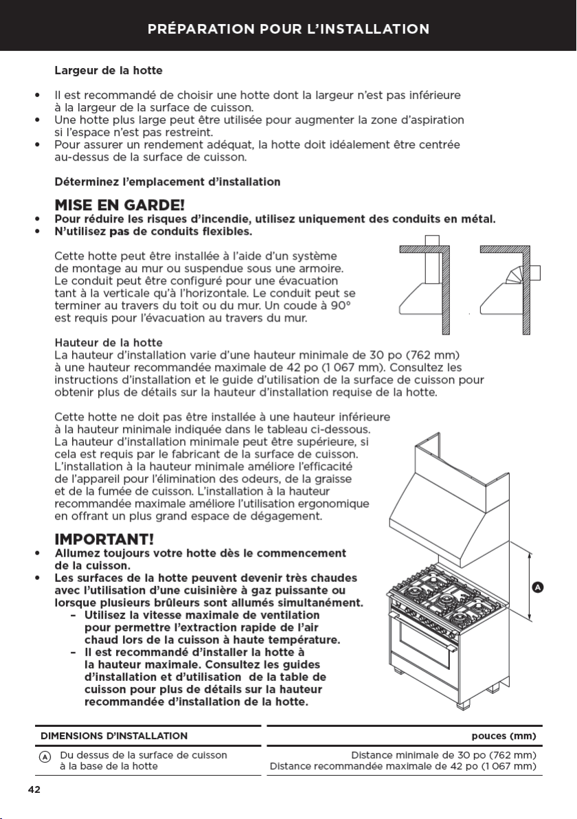
Venting requirements
CAUTION!
To reduce risk of fire and to properly exhaust air, be sure to duct air outside — Do not vent
exhaust air into spaces within walls or ceilings or into attics, crawl spaces, or garages.
●
The range hood can be installed to operate with the exhaust air ducted externally
fromthe kitchen.
●
Use the shortest and straightest duct route possible, for optimal efficiency.
Elbowsandtransitions increase noise and reduce air flow efficiency.
●
For best results:
– In ducted installations with internal blowers use 8” (203mm) round ducting.
– For inline blowers use 10” (254mm) round ducting.
Note: This range hood cannot be used in conjunction with a recirculation unit.
Make-up air (not included)
Attention should be given to ensure that any applicable regulations concerning the
discharge of exhaust air are fulfilled.
●
Local building codes may require the use of make-up air systems when using ducted
ventilation systems greater than specified cubic feet per minute (CFM) of air movement.
The specified CFM varies from locale to locale.
●
It is the responsibility of the owner and the installer to determine if additional
requirements and/or standards apply to specific installations.
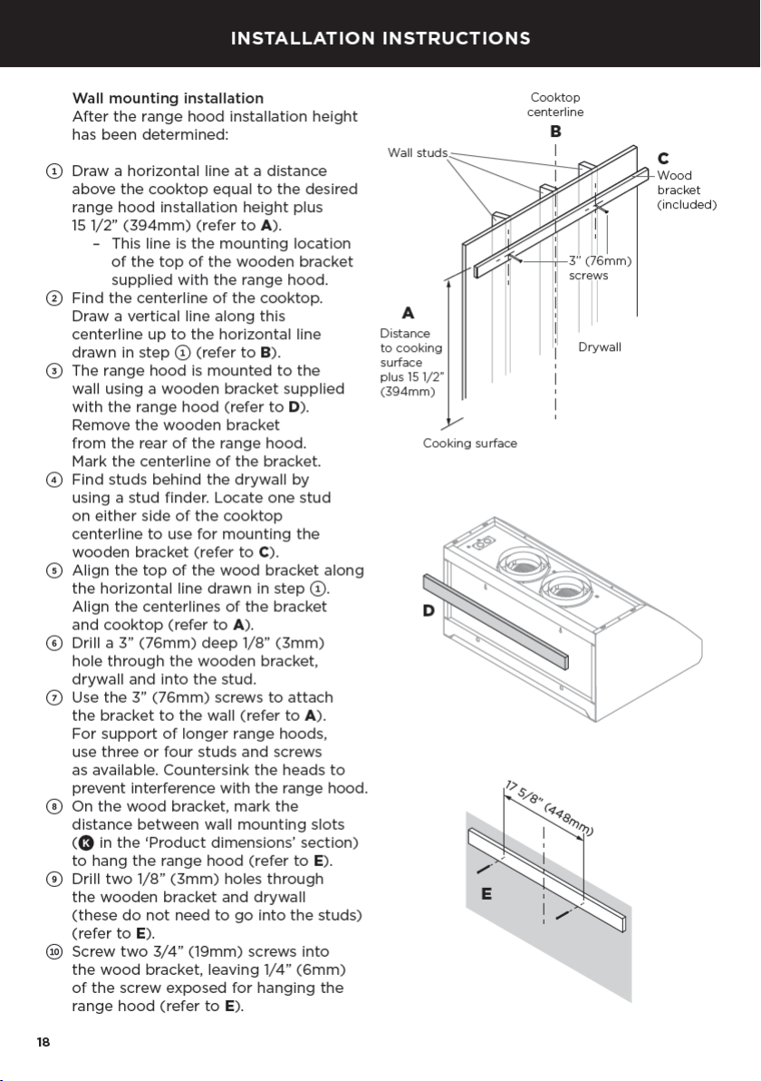
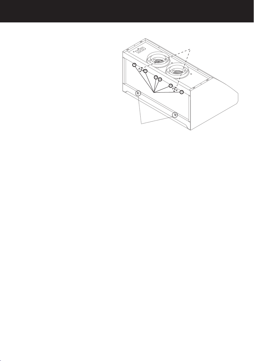
19
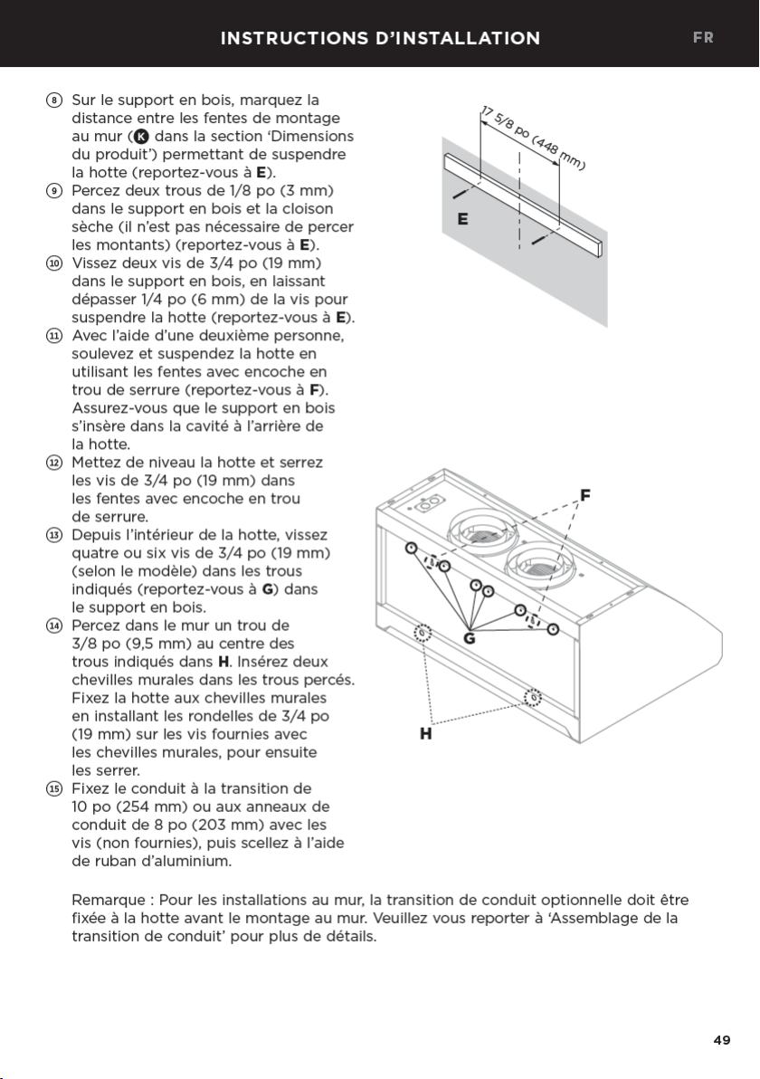
!1
Using two people lift and hang
the range hood using the keyhole
slots (refer to F). Make sure the
wood bracket fits into the recess
on the back of the range hood.
!2
Level the range hood and tighten
the3/4” (19mm) screws in the
keyhole slots.
!3
From inside the range hood, drive
four or six 3/4” (19mm) screws
(depending on model) through
the holes indicated (refer to G)
into the wooden bracket.
!4
Drill a 3/8” (9.5mm) hole through
the center of the holes indicated
in H into the wall. Insert two wall
plugs into the drilled holes.
Tighten the range hood to the wall
plugs by installing the 3/4” (19mm)
washers onto the screws supplied
with the wall plug, then tighten.
!5
Attach the duct to the 10” (254mm)
transition or the 8” (203mm)
duct rings and screws (not supplied)
and seal with aluminum tape.
G
F
H
EN
Note: For wall installations the optional duct transition should be fitted to the range
hood prior to wall mounting. Please refer to ‘Duct transition assembly’ for details.
20
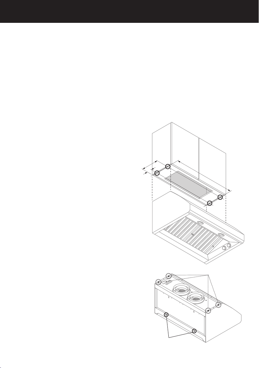
Cabinet mounting installation
The range hood can be installed under a cabinet by supporting the range hood from
thetop. For cabinet mounting installation the transition should be mounted after
installing the range hood, see ‘Duct transition assembly’ and ‘Product dimensions’
sections. Ifthe transition is used allowance needs to be made in the cabinetry back
wallfor easier ducting attachment and sealing.
WARNING!
The cabinet must be of sufficient strength and structurally joined to the wall studs
tosupport the weight of this range hood.
IMPORTANT!
It is recommended that the cabinet has a door or service panel that can be easily
opened to access the power connection box.
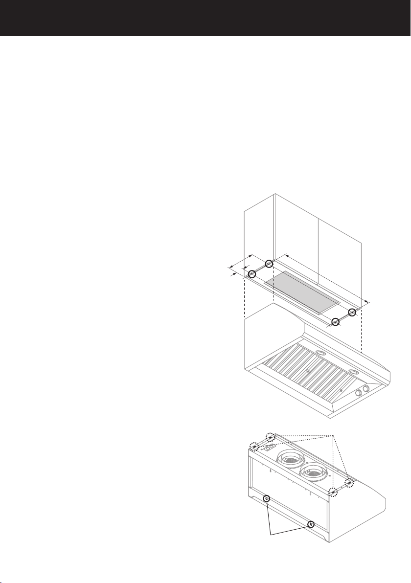
1
To determine the location for the four
screwsthat will secure the range hood
tothe cabinet, refer to ‘Product dimensions’
formeasurements of
L
,
M
and
N
.
2
Draw a line to mark distance
L
along
theunderside of your cabinet.
3
At either end of
L
, draw two lines,
oneatdistance
M
from the wall, the
otherone at distance
N
from the wall.
This will give you the 4 positions for
thescrew holes.
Note: Allow space for the power conduit, and
ducting attachment in the cabinetry base.
4
In the base of the cabinet, drill 1/8” (3mm)
holes as marked.
5
Screw four 3/4” (19mm) screws leaving
1/4” (6mm) of the screw exposed to hang
the range hood on.
6
Using two people lift and hang the range
hood from the screws through keyslots
provided on range hood top (refer to I).
Tighten the four screws.
7
Drill a 3/8” (9.5mm) hole through the center
of the holes indicated in H into the wall.
Insert two wall plug into the drilled holes.
Tighten the range hood to the wall plugs
by installing the 3/4” (19mm) washers onto
the screws supplied with the wall plug,
thentightening.
8
If using a optional duct transition, attach
the10” (254mm) transition now, see
‘Duct transition assembly’ section for details.
9
Attach the duct to the 10” (254mm) transition
or 8” (203mm) duct rings with screws
(notsupplied) and seal with aluminum tape.
M
N
L
H
I
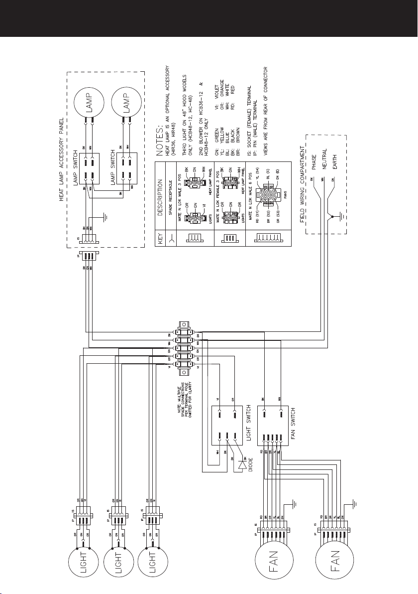
23
Wiring diagram
EN

27
MAINTENANCE
Light bulb replacement
IMPORTANT!
●
Wear gloves to protect against sharp edges.
●
DO NOT TOUCH the light bulb when in use. They may be hot enough to cause injury.
Note: Replacement bulbs are not covered by warranty.
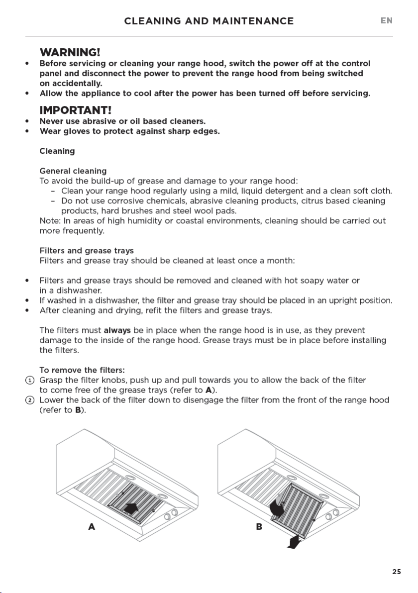
To replace the light bulb:
●
Turn off the range hood and allow the light bulb to cool.
●
Disconnect the power.
●
To remove the light bulb push up and twist counterclockwise.
●
Replace with a new 120V, 50W maximum light bulb (or equivalent dimmable LED)
lightwith a GU10 base.
●
Repeat steps for the other light bulbs if needed.
●
Reconnect power.
●
If new lights do not operate, ensure the bulbs are inserted correctly before calling
aservice representative.
Replacing the infra-red heat lamp (optional accessory)
WARNING!
To avoid any electrical shock the installation of the infra-red heat lamp and panel kit
should be done by a qualified electrician and before starting the installation of the
range hood.
Optional infra-red heat lamp panel can be ordered separately and mounted into
yourrange hood, see the ‘Parts and accessories’ section.
●
Turn off the range hood and allow the infra-red heat lamp to cool.
●
Disconnect the power.
●
Remove the infra-red heat lamp bulb by twisting counter clockwise.
●
Replace with a new 120V, 175W maximum infra-red bulb with a E26 screw in fitting.
●
Repeat steps for the other lamp if needed.
●
Reconnect power.
●
If new lamps do not operate, ensure the bulbs are inserted correctly before calling
aservice representative.
EN
28
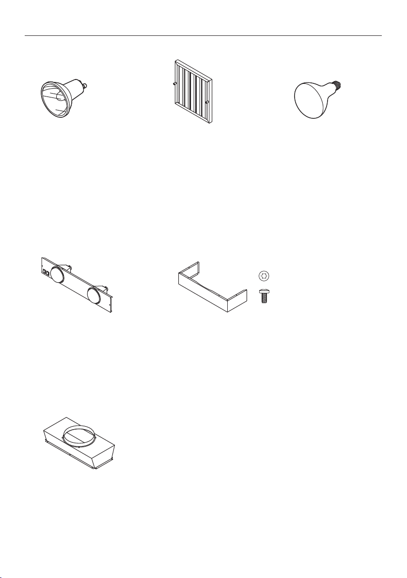
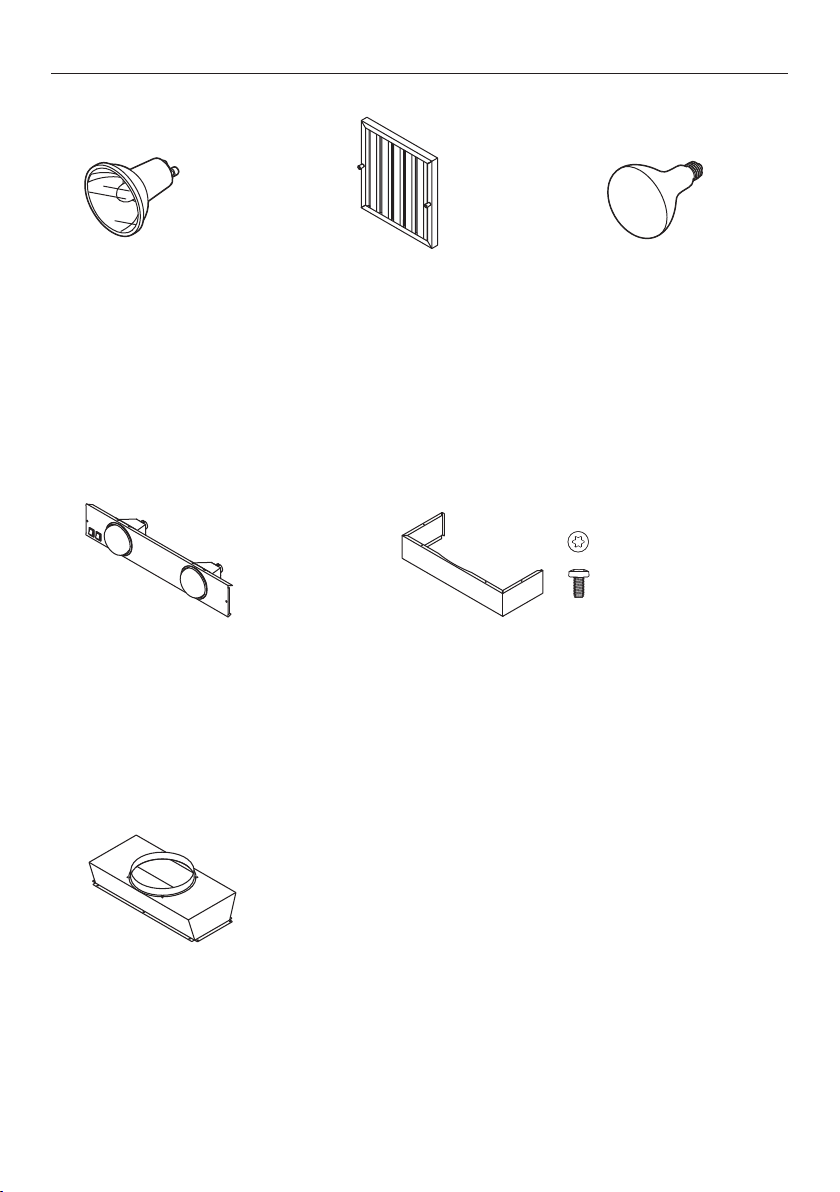
PARTS AND ACCESSORIES
Duct transition 10” (254mm)
outlet including 5/16” (8mm)
T20 (TORX) machine head
screws (12) (50129)
Heat lamp panel with
2x infra-red bulbs
(175W each) and
3/4” (19mm) screws (2)
●
36” heat lamp panel
(HIR36) (50080)
●
48” heat lamp panel
(HIR48) (50081)
Duct covers (stainless steel) including
5/16” (8mm) T20 (TORX) machine head screws (6)
●
30”Duct cover 6” (152mm) high (50092)
●
36” Duct cover 6” (152mm) high (50076)
●
48” Duct cover 6” (152mm) high (50078)
●
30” Duct cover 12” (305mm) high (50093)
●
36” Duct cover 12” (305mm) high (50077)
●
48” Duct cover 12” (305mm) high (50079)
2 x Halogen light bulbs
120V 50W
Filters
●
117/8” (301mm)
●
137/8” (352mm)
Parts
Accessories
Infra-red heat lamp
120V 175W
Note: Above are the commonly used spare parts. To purchase these and any other
spare parts please refer to your country specific section in the separate service and
warranty book.

29
SERVICE AND WARRANTY
For details of your Manufacturer’s Warranty and contacts for servicing, please refer to
your separate service and warranty book provided with your range hood.
Complete and keep for safe reference:
Model
Serial No.
Purchase Date
Purchaser
Dealer
City
State
Zip
Country
EN


31
TABLE DES MATIÈRES
IMPORTANT!
CONSERVEZ CES INSTRUCTIONS
Les modèles illustrés dans ce guide d’utilisation
peuvent ne pas être disponibles dans tous
les pays et sont sujets à modifications sans
préavis. Pour les plus récentes informations
sur la disponibilité des modèles et des
caractéristiques dans votre pays, veuillez visiter
notre site Web fisherpaykel.com ou contacter
votre détaillant Fisher&Paykel local.
Enregistrement
Enregistrez votre produit afin que nous
puissions vous offrir un service de la
meilleure qualité possible.
Pour enregistrer votre produit, visitez notre
site Web : fisherpaykel.com
FR
Introduction 33
Consignes de sécurité et mises en garde 34
Informations sur le produit 36
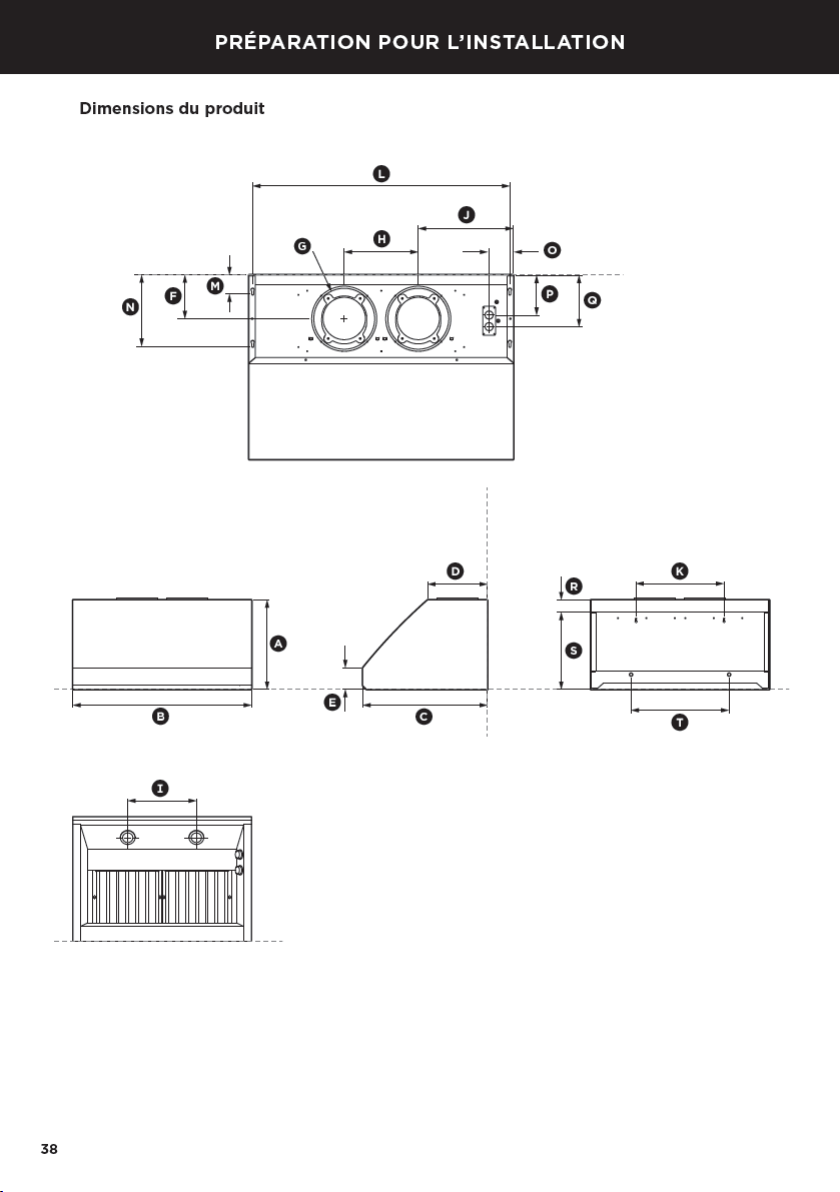
Préparation pour l’installation 38
Instructions d’installation 46
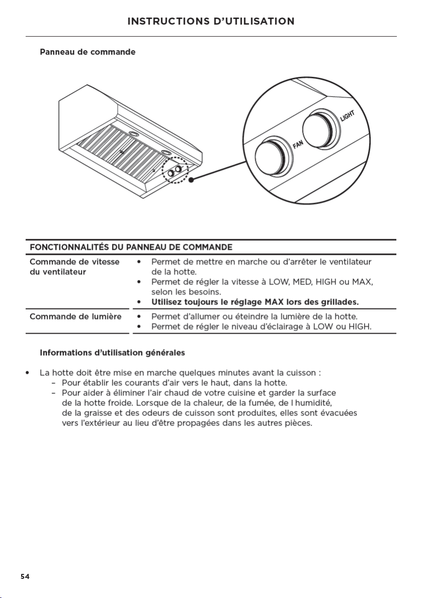
Instructions d’utilisation 54
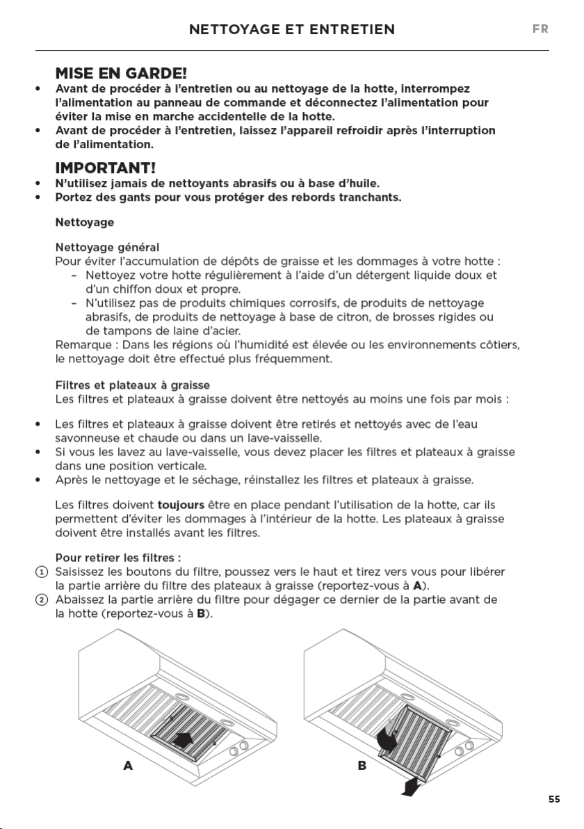
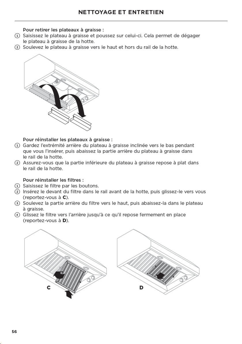
Nettoyage et entretien 55
Entretien 57
Pièces et accessoires 58
Service et garantie 59

33
INTRODUCTION
Bienvenue dans le monde des appareils Fisher&Paykel. Notre équipe a consacré
desmilliers d’heures à la conception, l’ingénierie et la mise à l’essai afin de vous offrir
leproduit idéal pour votre maison. Pour plus d’informations, visitez notre site Web;
pourune assistance supplémentaire, communiquez avec notre équipe de service à
laclientèle.
FR

35
CONSIGNES DE SÉCURITÉ ET MISES EN GARDE
carneau(cheminée) de l’appareil. Suivez les consignes du fabricant de
l’appareilde cuisson ainsi que les normes de sécurité comme celles publiées
par la National Fire Protection Association (NFPA) et la American Society for
Heating, Refrigeration and Air Conditioning Engineers (ASHRAE), ainsi que
lesnormes locales.
– Au moment de couper ou percer le mur ou le plafond, veillez à ne pas
endommager le câblage électrique ou les conduites qui y sont dissimulés.
– Les ventilateurs avec conduits doivent toujours évacuer l’air vers l’extérieur.
– Cet appareil doit être mis à la terre.
ATTENTION: Pour réduire les risques d’incendie et évacuer l’air adéquatement,
assurez-vous d’évacuer l’air vers l’extérieur. N’évacuez pas l’air dans les murs,
plafonds, greniers, vides sanitaires ou garages.
MISE EN GARDE: Pour réduire les risques d’incendie, utilisez uniquement des
conduitsen métal.
MISE EN GARDE: Pour réduire les risques d’incendie ou de choc électrique, n’utilisez
pas ce ventilateur avec un dispositif de contrôle de vitesse à semi-conducteurs.
MISE EN GARDE: Pour réduire les risques de feu de graisse sur la cuisinière:
– Ne laissez jamais les éléments de surface sans surveillance lors de l’utilisation
deréglages élevés. Les débordements produisent de la fumée et des
déversements de matières grasses qui peuvent s’enflammer.
– Chauffez les huiles lentement, à feu doux ou moyen.
– Allumez toujours la hotte lorsque vous cuisinez à feu vif ou faites flamber
desaliments (par ex.: crêpes Suzette, cerise jubilé, steak au poivre flambé).
– Nettoyez fréquemment les ventilateurs. Ne laissez jamais la graisse s’accumuler
sur le ventilateur ou le filtre.
– Utilisez des récipients de taille appropriée. Utilisez toujours des plats de cuisson
adaptés à la taille de l’élément de surface.
MISE EN GARDE: Pour réduire les risques de blessures en cas de feu de graisse sur
lacuisinière, respectez ces consignes*:
– Étouffez les flammes avec un couvercle hermétique, une plaque à biscuits ou
un plateau métallique, puis éteignez le brûleur. Faites attention de ne pas vous
brûler. Si les flammes ne s’éteignent pas immédiatement, évacuez la pièce et
appelez le service d’incendie.
– Ne prenez jamais un récipient qui est en flammes– vous pourriez vous brûler.
– N’utilisez pas de l’eau, ni de linges ou serviettes humides, car cela pourrait
causer une violente explosion de vapeur.
– Utilisez un extincteur uniquement si:
– Vous savez qu’il s’agit d’un extincteur de classe ABC et vous savez
vousenservir.
– Le feu est peu important et localisé dans la zone où il a commencé.
– Vous avez appelé le service d’incendie.
– Vous pouvez combattre le feu en ayant le dos tourné vers une sortie.
MISE EN GARDE: Toutes les ouvertures dans le mur et le plancher doivent être
scellées aux endroits où la hotte est installée.
LISEZ ET CONSERVEZ CES INSTRUCTIONS
* Tirés des conseils sur la sécurité en matière d’incendie de cuisine de la NFPA.
FR
36
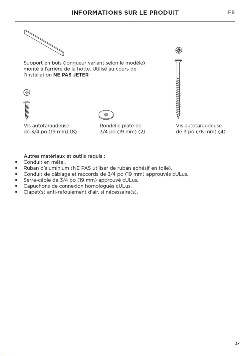
INFORMATIONS SUR LE PRODUIT
Informations générales
Veuillez lire attentivement ce manuel et conservez-le après l’installation pour obtenir
desréponses aux questions qui peuvent survenir pendant l’utilisation de votre
nouvellehotte Fisher&Paykel.
Conservez tous les matériaux d’emballage (boîte, palette, sangles) jusqu’à ce que
vousterminiez l’inspection de l’appareil. Inspectez le produit pour vérifier qu’aucun
dommage n’a été causé lors de l’expédition. En cas de dommages, communiquez
avecle détaillant qui vous a vendu le produit pour signaler les dommages.
Fisher&Paykel n’est pas responsable des dommages causés lors de l’expédition.
MISE EN GARDE!
Pour une utilisation résidentielle uniquement.
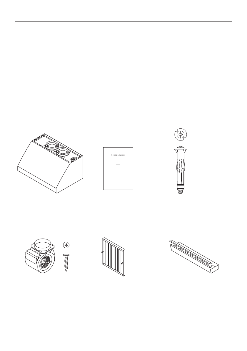
Pièces incluses avec votre hotte:
Guide d’utilisation (1)
I STA LAT ON GUIDE USER GU DE
UIDE D NSTA LAT ON / GU DE D’ TI IS TION
US CA
PROFESSIONAL RANGE HOOD
H B30 6 HC 36 6 HC 36 12 HCB48 2
HC36 Sh l ) & HC48 ( he ) mode s
HOTTE PROFESSIONNELLE
Mod l s HCB30 6 HCB36 6 CB36 12 HCB 8 2
HC36 ( oqu ) et HC 8 Coq e)
Ventilateur interne,
incluant les vis de 3/4po
(19mm) (4)
●
HCB30-6 (1)
●
HCB36-6 (1)
●
HCB36-12 (2)
●
HCB48-12 (2)
●
HC36/48 (0)
Filtres
●
HCB30 (2)
●
HCB36/HC36 (2)
●
HCB48/HC48 (3)
Plateaux à graisse
●
HCB30 (2)
●
HCB36/HC36 (2)
●
HCB48/HC48 (3)
Hotte avec ampoules et
anneaux de raccordement
de conduit de 8po
(203mm) installés (1)
Cheville murale (2)
¾ OD x 16 D
t
# 0 3
P zi r v
8
#10
Po i rive
FP Pr H od Fa en rs

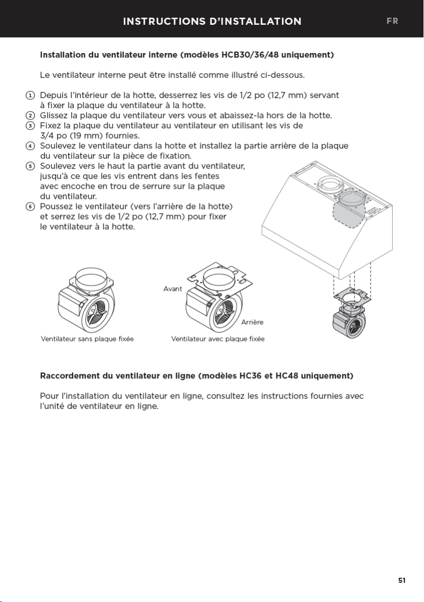
45
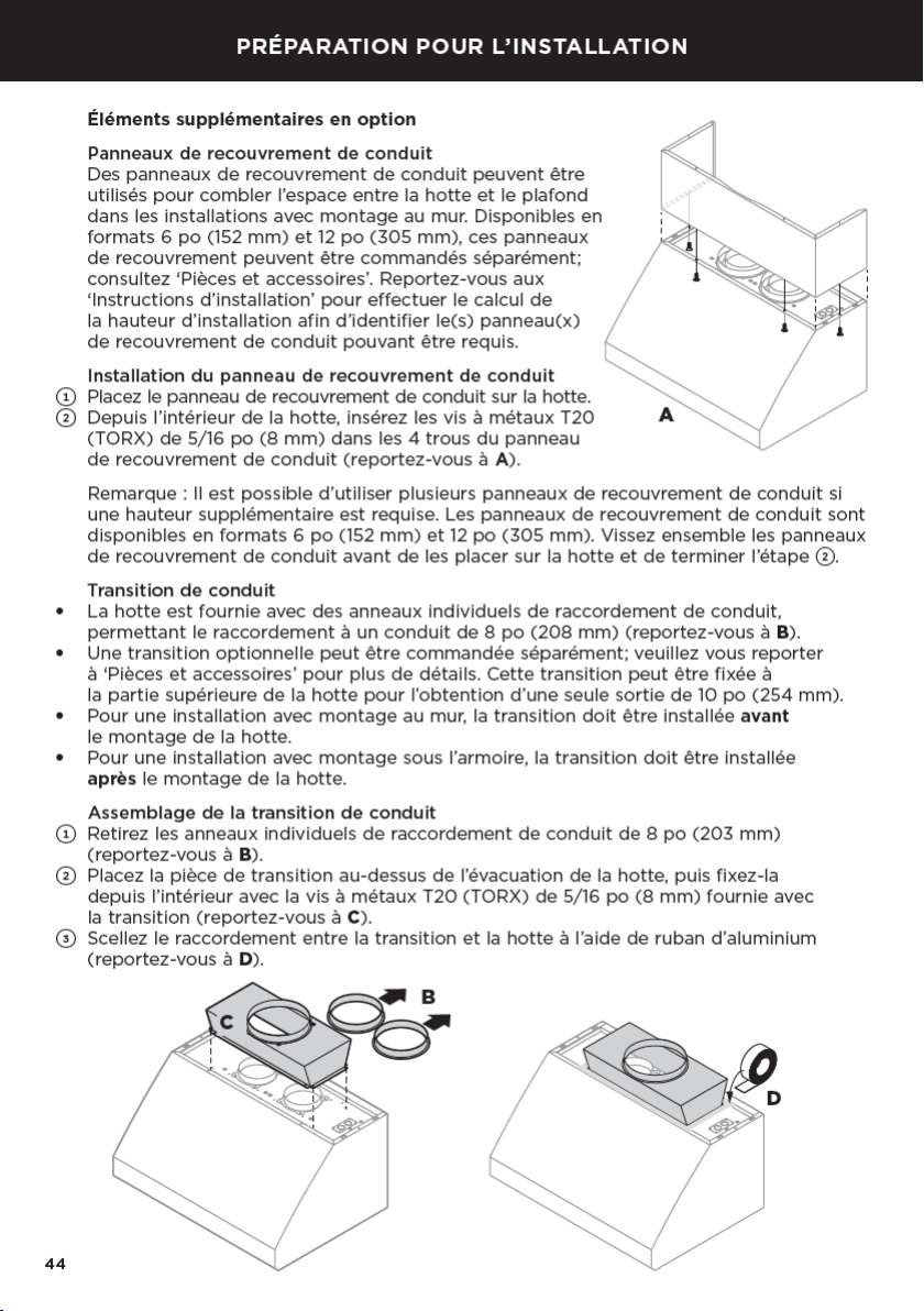
Ensemble de panneau et lampe infrarouge
Si vous avez fait l’acquisition d’un ensemble de lampe infrarouge en option pour
l’installation avec la hotte, assemblez l’ensemble avec la hotte avant l’installation.
Consultez les instructions fournies avec l’ensemble pour l’assemblage avec votre hotte.
MISE EN GARDE!
Pour éviter toute électrocution, faites installer l’ensemble de panneau et lampe
infrarouge par un électricien qualifié avant de commencer l’installation de la hotte.
FR
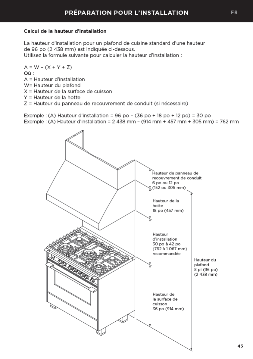
PRÉPARATION POUR L’INSTALLATION
FR
50
Installation avec montage à l’armoire
Vous pouvez installer la hotte sous une armoire en la fixant par la partie supérieure. Pour
l’installation avec montage à l’armoire, la transition doit être fixée après l’installation de
la hotte; consultez les sections ‘Assemblage de la transition de conduit’ et ‘Dimensions
du produit’. Si la transition est utilisée, vous devez prévoir de l’espace dans le mur arrière
de l’armoire pour faciliter la fixation et le scellement du conduit.
MISE EN GARDE!
L’armoire doit être suffisamment solide et reliée structurellement aux montants du
mur pour supporter le poids de cette hotte.
IMPORTANT!
Il est recommandé que l’armoire possède une porte ou un panneau pouvant s’ouvrir
facilement pour donner accès au boîtier de raccordement d’alimentation.
1
Pour déterminer l’emplacement des quatre
vis qui serviront à fixer la hotte à l’armoire,
reportez-vous à ‘Dimensions du produit’
pour les mesures de
L
,
M
et
N
.
2
Tracez une ligne pour marquer la distance
L
le long du dessous de votre armoire.
3
À une extrémité ou l’autre de
L
, tracez
deux lignes, l’une à la distance
M
à partir
du mur, l’autre à la distance
N
à partir
du mur. Cela vous donnera les 4positions
pour les trous de vis.
Remarque: Laissez un espace pour le conduit
d’alimentation électrique et la fixation du
conduit dans la base de l’armoire.
4
Dans la base de l’armoire, percez des trous
de 1/8po (3mm) aux endroits marqués.
5
Vissez quatre vis de 3/4po (19mm) en
laissant dépasser 1/4po (6mm) de la vis
pour suspendre la hotte.
6
Avec l’aide d’une deuxième personne,
soulevez et suspendez la hotte par les vis
en utilisant les encoches en trou de serrure
sur le dessus de la hotte (reportez-vous à I).
Serrez les quatre vis.
7
Percez dans le mur un trou de 3/8po
(9,5mm) au centre des trous indiqués dans G.
Insérez deux chevilles murales dans les trous
percés. Fixez la hotte aux chevilles murales
en installant les rondelles de 3/4po (19mm)
sur les vis fournies avec les chevilles murales,
pour ensuite les serrer.
8
Si vous utilisez une transition de conduit
optionnelle, fixez la transition de 10po
(254mm) maintenant; consultez la section
‘Assemblage de la transition de conduit’
pour plus de détails.
9
Fixez le conduit à la transition de 10po
(254mm) ou aux anneaux de conduit de
8po (203mm) avec les vis (non fournies),
puis scellez à l’aide de ruban d’aluminium.
M
N
L
INSTRUCTIONS D’INSTALLATION
H
I
53
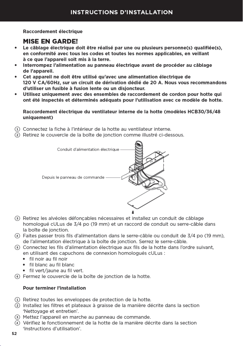
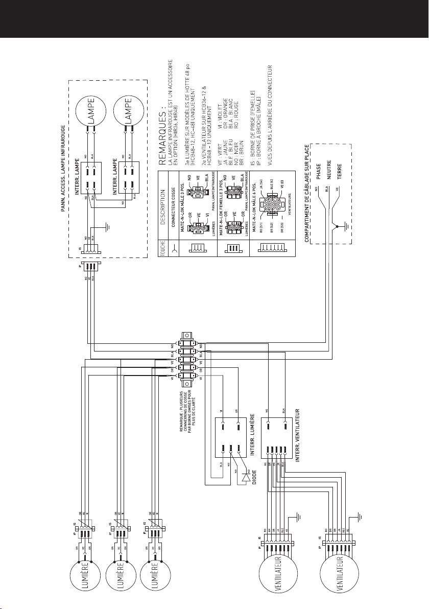
Schéma de câblage
INSTRUCTIONS D’INSTALLATION
FR

57
ENTRETIEN
Remplacement de l’ampoule
IMPORTANT!
●
Portez des gants pour vous protéger des rebords tranchants.
●
NE TOUCHEZ PAS à l’ampoule pendant l’utilisation. Elle pourrait être suffisamment
chaude pour causer des blessures.
Remarque: Les ampoules de rechange ne sont pas couvertes par la garantie.
Pour remplacer l’ampoule:
●
Éteignez la hotte et laissez refroidir l’ampoule.
●
Déconnectez l’alimentation.
●
Pour retirer l’ampoule, poussez vers le haut et tournez dans le sens inverse des aiguilles
d’une montre.
●
Remplacez-la par une nouvelle ampoule de 120V, 50W maximum (ou DEL équivalente
à gradation) avec une base GU10.
●
Répétez les étapes pour les autres ampoules, si nécessaire.
●
Reconnectez l’alimentation.
●
Si les nouvelles ampoules ne fonctionnent pas, assurez-vous que les ampoules sont
insérées correctement avant d’appeler un représentant de service.
Remplacement de la lampe infrarouge (accessoire en option)
MISE EN GARDE!
Pour éviter toute électrocution, faites installer l’ensemble de panneau et lampe
infrarouge par un électricien qualifié avant de commencer l’installation de la hotte.
Le panneau de lampe infrarouge en option peut être commandé séparément et fixé
sur votre hotte; consultez la section ‘Pièces et accessoires’.
●
Éteignez la hotte et laissez refroidir la lampe infrarouge.
●
Déconnectez l’alimentation.
●
Retirez l’ampoule de la lampe infrarouge en tournant dans le sens contraire des
aiguilles d’une montre.
●
Remplacez-la par une nouvelle ampoule infrarouge 120V, 175W maximum avec
raccord vissé E26.
●
Répétez les étapes pour l’autre lampe, si nécessaire.
●
Reconnectez l’alimentation.
●
Si les nouvelles lampes ne fonctionnent pas, assurez-vous que les ampoules sont
insérées correctement avant d’appeler un représentant de service.
FR
58
PIÈCES ET ACCESSOIRES
Transition de conduit avec
sortie de 10po (254mm)
incluant des vis à métaux T20
(TORX) de 5/16po (8mm) (12)
(50129)
Panneau de lampe infrarouge
avec 2ampoules infrarouges
(175W chacune) et vis de
3/4po (19mm) (2)
●
Panneau de lampe infrarouge
de 36po (HIR36) (50080)
●
Panneau de lampe infrarouge
de 48po (HIR48) (50081)
Panneaux de recouvrement de conduit
(acierinoxydable) incluant des vis à métaux
T20(TORX) de 5/16po (8mm) (6)
●
Panneau de recouvrement de conduit de 30po,
hauteur de 6po (152mm) (50092)
●
Panneau de recouvrement de conduit de 36po,
hauteur de 6po (152mm) (50076)
●
Panneau de recouvrement de conduit de 48po,
hauteur de 6po (152mm) (50078)
●
Panneau de recouvrement de conduit de 30po,
hauteur de 12po (305mm) (50093)
●
Panneau de recouvrement de conduit de 36po,
hauteur de 12po (305mm) (50077)
●
Panneau de recouvrement de conduit de 48po,
hauteur de 12po (305mm) (50079)
2ampoules halogènes
120V 50W
Filtres
●
117/8po (301mm)
●
137/8po (352mm)
Pièces
Accessoires
Lampe infrarouge
120V 175W
Remarque: Les pièces détachées ci-dessus sont couramment utilisées. Pour acheter
cespièces et toute autre pièces de rechange, veuillez consulter la section de votre
pays dans le manuel de service et de garantie séparé.

59
SERVICE ET GARANTIE
Pour plus de détails sur la garantie du fabricant et les coordonnées pour le service,
veuillez vous reporter au manuel d’entretien et de garantie distinct, fourni avec votre hotte.
Remplir et conserver pour référence ultérieure:
Modèle
N° de série
Date d’achat
Acheteur
Détaillant
Ville
État/Province
Code postal
Pays
FR


US CA
104907C 04.18
FISHERPAYKEL.COM
© Fisher & Paykel Appliances 2018. All rights reserved.
The product specifications in this booklet apply to the specific products
and models described at the date of issue. Under our policy of continuous
product improvement, these specifications may change at any time. You
should therefore check with your Dealer to ensure this booklet correctly
describes the product currently available.
© Fisher & Paykel Appliances 2018. Tous droits réservés.
Les caractéristiques de produit présentées dans ce livret s’appliquent aux
modèles et produits spécifiques qui y sont décrits à la date de publication.
Dans le cadre de notre politique d’amélioration en permanence de nos
produits, ces caractéristiques peuvent être modifiées à tout moment.
Nous vous recommandons de vérifier auprès de votre détaillant que ce
livret décrit le produit actuellement disponible.