Loading ...
Loading ...
Loading ...
10
Gas supply
• Check that the appliance is set for the type of gas available
and then connect it to the mains gas piping or the gas
cylinder in compliance with the applicable norms in force.
• This appliance is designed and set to work with the gas
indicated on the label situated on the actual hob. If the gas
supply is different from the type for which the appliance
has been set, replace the corresponding nozzles
(provided), following the instructions given in the paragraph
"Adaptation to different types of gas".
• For trouble-free operation, suitable use of energy and a
longer life cycle for the appliance, make sure that the supply
pressure complies with the values indicated in table 1
"Burner and nozzle specifications", otherwise install a
special pressure regulator on the supply pipe in compliance
with current standards and regulations.
• Connect in such a way that the appliance is subjected to
no strain whatsoever.
Either a rigid metal pipe with fittings (fig. 12-D) in compliance
with norms must be used for connecting to the nipple union
(threaded - cylindrical ½"G fitting "F") situated at the rear of
the appliance (fig. 12), or a flexible steel pipe with a
continuous wall and fittings (fig. 12-C) in compliance with
norms, which must not exceed 2000 mm in length. Check
that the connecting pipe cannot come into contact with
moving parts which could damage or crush it. For installation
with a flexible rubber pipe, apply the special hose support
for liquid gas (fig. 12-A) or natural gas (fig. 12-B). The
gasket "G" (provided) must be utilised in every type of
connection. The two ends of the pipe must be fastened with
the purpose designed pipe collars "E", in compliance with
the norms. The flexible pipe should comply with the norms,
and be specific for the type of gas used. In addition:
• it should be as short as possible, with a maximum length
of 1.5 metres;
• it should not be bent or kinked;
• it should not be in contact with the rear panel of the appli-
ance or in any case with parts which may reach a tem-
perature of 50°;
• it should not pass through holes or slits used for discharg-
ing the oven flue gases;
• it should not come into contact with pointed parts or sharp
corners;
• it should be easy to inspect along its entire length in or-
der to be able to check its condition;
• it should be replaced before the date printed on the ac-
tual pipe.
A
fig.13
fig.12
Important: A pressure regulator, in compliance with the
applicable norm in force, must be inserted when
connecting to a liquid gas supply (in a cylinder).
Upon completion of installation, check for leaks from the gas
circuit using a soapy solution (never use a flame). Make sure
that the natural gas pipe is adequate for a sufficient supply
to the appliance when all the burners are lit.
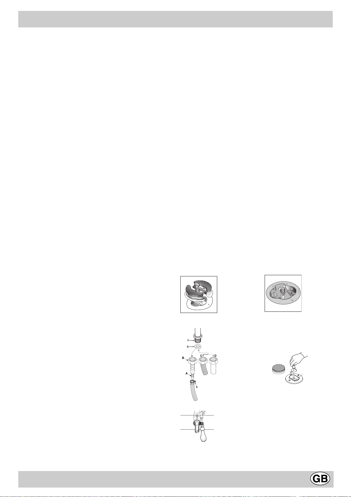
Adapting to different types of gas (instructions for the hob)
To adapt the hob to a different type of gas from the factory-
set one (indicated on the rating plate at the top of the hood
or on the packaging), the burner nozzles should be replaced
as follows:
• Remove the hob grids and slide the burners off their seats.
• Unscrew the nozzles (fig. 13), using a 7 mm socket span-
ner and replace them with nozzles for the new type of gas
(see table 1 "Burner and nozzle characteristics").
Reassemble the parts following the above procedure in
the reverse order.
• On completion of this operation, replace the old rating
sticker with one indicating the new type of gas used. This
sticker is available in the "kit of nozzle".
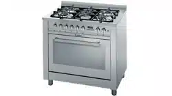
Replacing the independent "double flame" burner
nozzles:
• Remove the grids and slide the burners off their seats.
The burner is made up of three separate parts (see Fig.
C and Fig. D);
• Unscrew the nozzles using a 7 mm socket spanner. The
inner burner has one nozzle, while the outer one has two
(of the same size). Replace the nozzles with those for
the new type of gas (see table 1).
• Replace all the parts, following the steps described above
in the reverse order.
Fig. C Fig. D
sufficient capacity to guarantee an hourly exchange of air
equal to 3 ÷ 5 times the volume of the kitchen. Prolonged,
intensive use of the appliance may require extra ventilation,
e.g. an open window or a more efficient ventilation system by
increasing the extraction power of the electric fan if installed.
Liquid petroleum gas descends towards the floor as it is
heavier than air. Apertures in the outside walls in rooms
containing LPG cylinders should therefore be at floor level,
in order to allow any gas from leaks to be expelled. Do not
store LPG cylinders (even when empty) in basements/rooms
below ground level; it is advisable to keep only the cylinder in
use in the room and connected far from heat sources which
could raise its temperature to above 50°C.
INSTRUCTIONS FOR THE INSTALLER
fig.14
Loading ...
Loading ...
Loading ...