Use and Care & Installation Guide
Icemaker Accessory Kit
GE Quality Product
Installer: Please leave this guide with the Consumer.
Model UK-KIT-3S for refrigerators with
the freezer on the bottom
Safety Instructions.........................2
Operating Instructions...........2, 3
Installation
Kit Installation.............................................5–8
Water Line Installation ..........................9–11
Problem Solver .................................4
More questions ?…call
GE Answer Center® 800.626.2000
Consumer Services
Repair Service .................................................4
Warranty ........................................Back Cover
2
IMPORTANT SAFETY INSTRUCTIONS
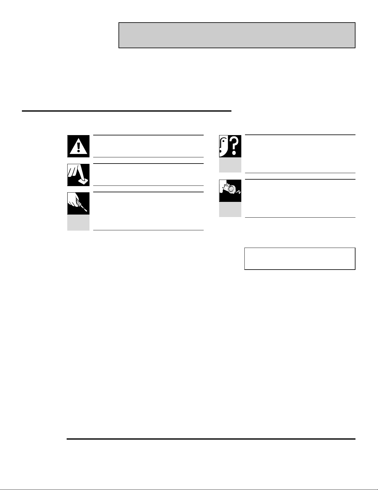
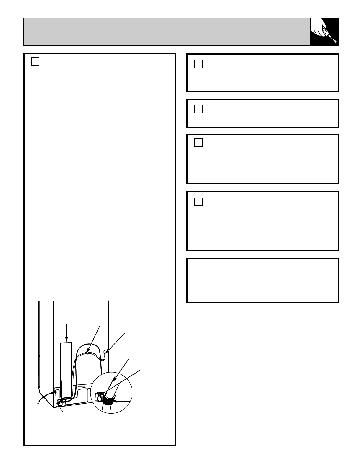
HOW THE ICEMAKER WORKS
Do not place fingers or hands on the automatic
icemaking mechanism while the refrigerator is
plugged in. This will help protect you from
possible injury. It will also prevent interference
with moving parts of the ejector mechanism and
the heating element that releases the cubes.
SAVE THESE
INSTRUCTIONS
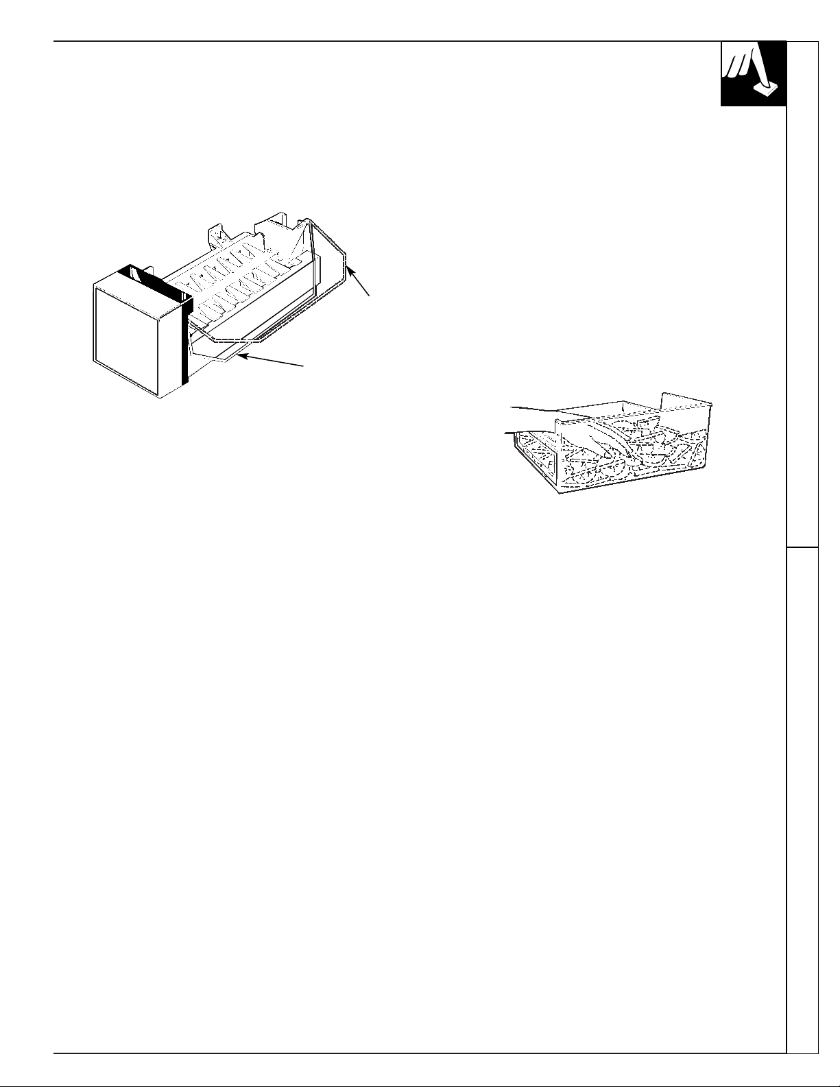
Water fills the empty cube mold when the freezer has
cooled to freezing temperature. Cold air is forced
directly over mold.
When frozen, the cubes are moved up and out of the
mold. The sweeper arm ejects them into the ice
storage bin below.
The feeler arm senses when the bin is full and signals
the icemaker to stop ejecting more cubes. However,
the mold has been refilled and cubes frozen so the
new supply is ready when needed. As soon as ice is
removed from the bin, the feeler arm signals that
more is needed. Icemaker resumes operation by
ejecting ready-and-waiting frozen cubes.
Sweeper Arm
Ice
Ice Storage Bin
Feeler Arm
Ice
Storage
Bin
3
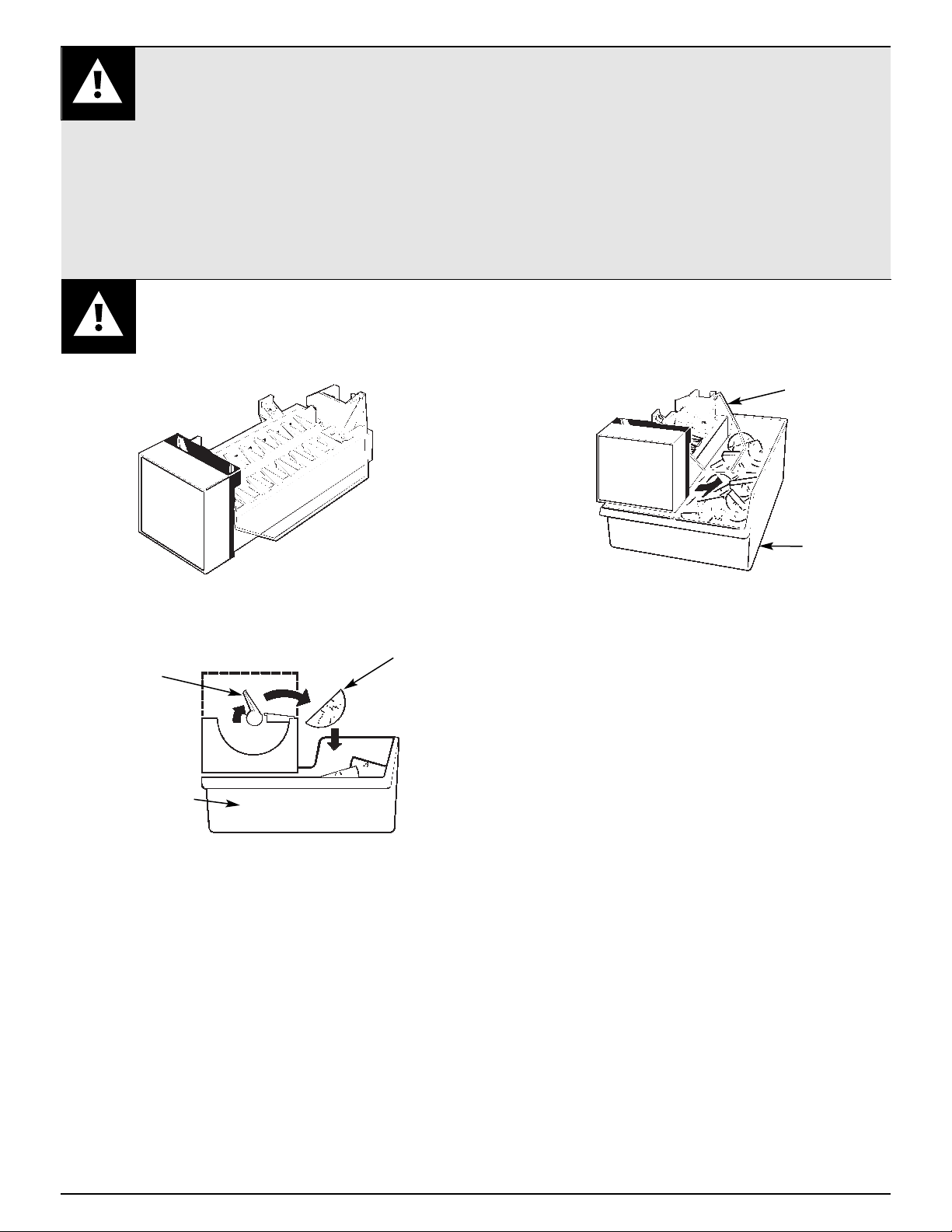
HOW TO USE YOUR ICEMAKER
1. To start the Icemaker, lower the feeler arm to the
ON (down) position. Make sure the ice storage
bin is below the icemaker and pushed back as far
as possible.
2. When the Icemaker is first connected or after any
extended period of non-use, you should discard the
first few batches of cubes. Use ice regularly to
maintain the best quality.
3. The feeler arm must be free to operate upward and
outward over the top of the ice storage bin during
each ice-delivery cycle. Make sure packages in the
freezer compartment do not block its movement.
4. Raise the feeler arm to the STOP (up) position
when:
a. Ice storage bin is to be removed for extended
period of time.
b. Refrigerator is not to be used for an extended
time, such as vacations. Also, turn off the water
supply to the Icemaker in this instance.
c. Water supply is to be shut off for several hours.
5. During operation, you may hear certain sounds,
such as the hum of the motor, movement of the
cube ejector, humming or clicking of the water
valve, and rattling of ice as it falls into the bin.
These sounds are normal.
6. The Icemaker ejects cubes in groups and it is
normal for several cubes to be joined together.
7. Ice cubes that have been in the ice storage bin
for a considerable length of time may pick up
off-flavor tastes, stick together, and gradually
become smaller. We suggest that these cubes be
thrown away.
8. You may, on occasion, find a few smaller than
normal cubes in the bin. This is probably caused by
low water pressure at time of water fill, and is no
cause for concern.
9. The ice storage bin should be cleaned occasionally
in warm water. Rinse and wipe dry. Be sure to put
the icemaker feeler arm in the STOP (up) position
when cleaning the bin.
10. Keep the ice level to keep it coming. If the
cubes should build up in one area of the ice
storage bin after being ejected from the mold,
just level them out with your hand. Keep the
cubes distributed evenly and the bin can reach
its maximum cube capacity.
Important Safety Instructions Operating Instructions
Arm up—
stops
operation
Arm down—
icemaker will
operate
4
QUESTIONS?
USE THIS PROBLEM SOLVER
IFYOU NEED SERVICE
To obtain service, see your
warranty on the back page of this
guide.
We’re proud of our service and
want you to be pleased. If for
some reason you are not happy
with the service you receive, here
are three steps to follow for further
help.
FIRST, contact the people who
serviced your appliance. Explain
why you are not pleased. In most
cases, this will solve the problem.
NEXT, if you are still not pleased,
write all the details—including
your phone number—to:
Manager, Consumer Relations
GE Appliances
Appliance Park
Louisville, KY 40225
PROBLEM POSSIBLE CAUSE
ICEMAKER APPEARS • The feeler arm is in the STOP (up) position.
TO HAVE STOPPED
• The icemaker is not getting the necessary supply of water. Make sure the water
OPERATING
supply is connected and turned on. Check for kinks in the 1/4″ copper tubing.
Remove kinks or replace tubing if there are kinks.
• The freezer compartment is too warm. Turn the temperature control to a colder
setting. (See your refrigerator use and care guide.)
• The cubes are too small. The shutoff valve connecting the refrigerator to the
home water line may be clogged. Unclog it.
WATER OVERFLOWS • Let the icemaker produce three or four batches of ice. If the water still
ICE MOLD overflows, call for service.
ICE CUBES HAVE • Use icemaker regularly. Discard old cubes. Ice stored for an extended period
ODOR/TASTE may absorb odors which affect their taste.
• Ice storage bin needs to be emptied and washed.
• Unsealed packages in the refrigerator and/or freezer compartments may be
transmitting odor/taste to ice cubes.
• The interior of the refrigerator needs cleaning—see your refrigerator use and
care guide.
If you need more help…call, toll free:
GE Answer Center
®
800.626.2000
consumer information service
CAUTION
For your safety, unplug the refrigerator from its
electrical outlet to eliminate danger of electric
shock during installation.
ADDITIONAL MATERIALS YOU WILL NEED
• Copper tubing, shutoff valve and fittings
necessary to supply water to your refrigerator.
They are not included in UK-KIT-3S.
You can purchase a complete water supply kit
from your GE or Hotpoint dealer. Recommended
water supply kits are:
• Cat. No. WX8X2 with 15 feet of copper tubing.
• Cat. No. WX8X3 with 20 feet.
• Cat. No. WX8X4 with 25 feet.
NOTE: DO NOT USE A SELF-PIERCING
VALVE.
• Read these instructions all the way through before starting.
• IMPORTANT: OBSERVE ALL GOVERNING CODES AND ORDINANCES.
• Installer—Be sure to leave these instructions with the Consumer.
UK-KIT-3S INSTALLATION INSTRUCTIONS
TOOLS REQUIRED
• Blade-type screwdriver • Electric drill
• 1/4″ hex socket and driver • 1/4″ drill bit
• Adjustable wrench • 3/8″ drill bit
• 1/2″ open-end wrench • Hammer
• 3/8″ open-end wrench • Small knife
• Needle nose pliers • Bucket
• Masking tape • Towel
• Center punch
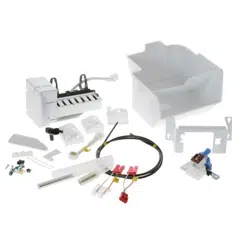
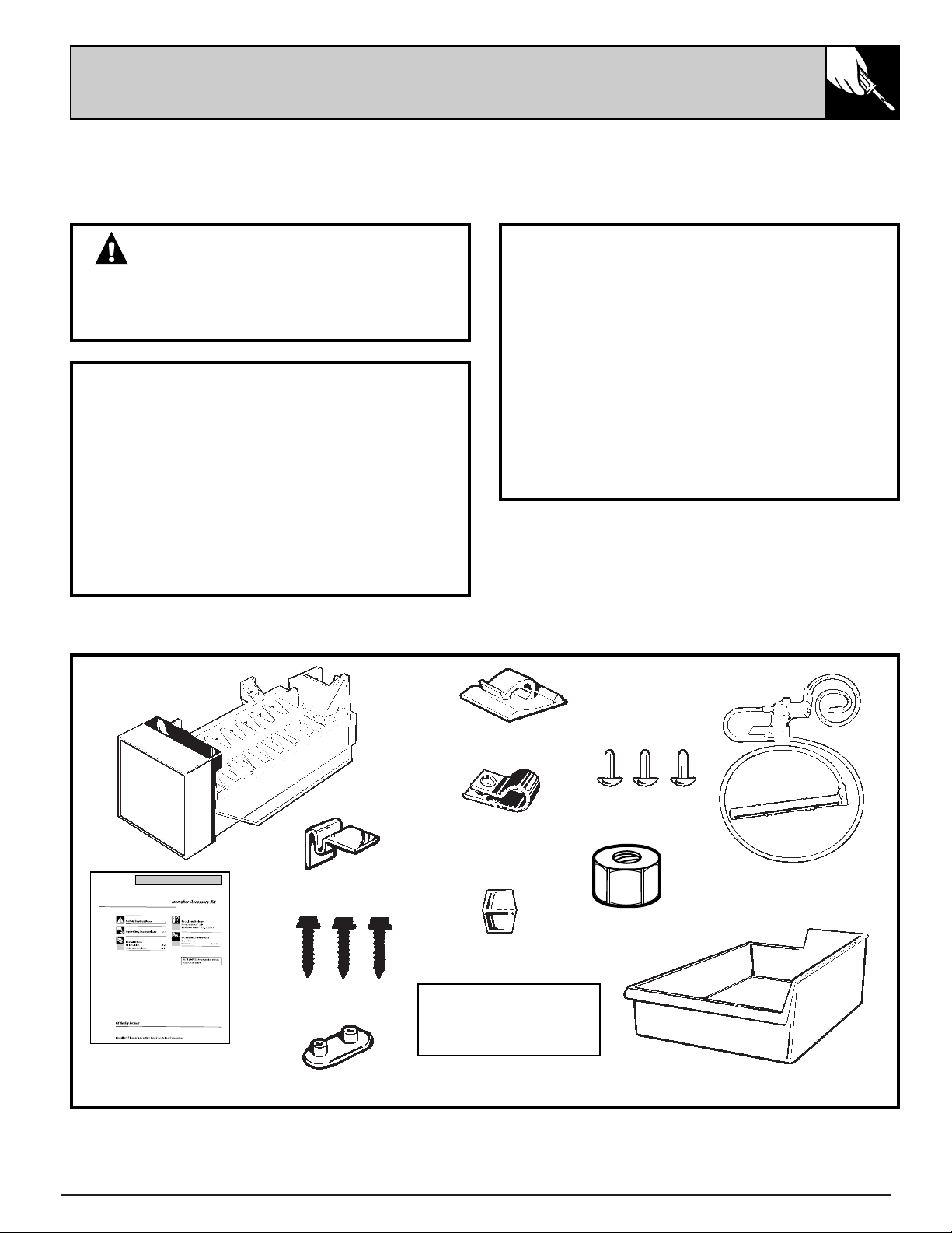
CONTENTS OF UK-KIT-3S
(continued next page)
Use and Care & Installation Guide
Ice Bucket
Icemaker
Water Valve Assembly
Double Prong Plugs
5/8″ Icemaker
Mounting Screws
Use & Care Instructions,
Installation Instructions
and Warranty
Warranty Label
ICE MAKER
WARRANTY VERIFICATION
Date Installed ________________
Dealer_______________________
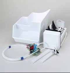
Plug Buttons
Ferrule
Flexible Plastic
Tubing
Water Tube
Compression Nut
Stainless Steel Clip
5
Plastic Stick-On Clamp
P-Clamp (used for
water line tubing)
6
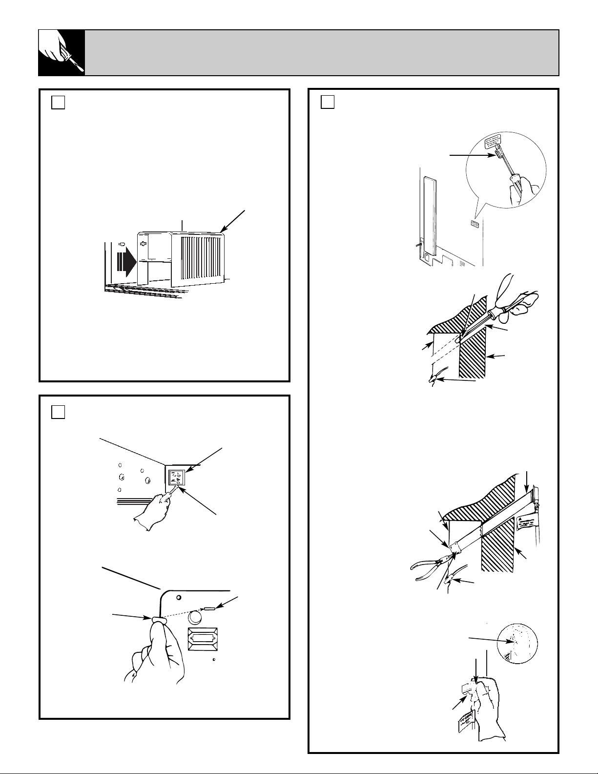
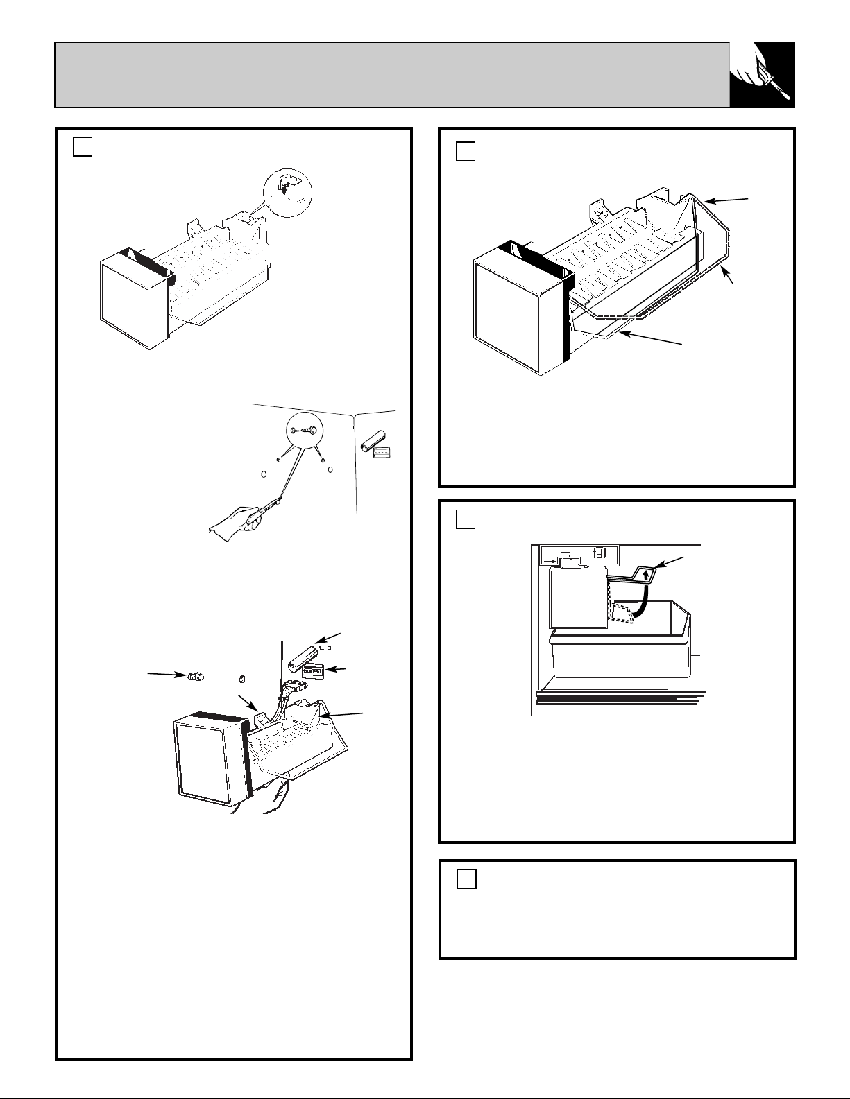
INSTALLTHE ICEMAKER
INSTALL WATER FILL TUBE THROUGH THE
BACK OF THE REFRIGERATOR.
a. Remove the
cover for the water
tube inlet hole on
the back of the
refrigerator near
the bottom. Use
a flat-blade
screwdriver
covered with
masking tape to
protect against
scratching the
refrigerator.
b. After
removing the
cover, use the
screwdriver to
pierce the interior
sealing tape that
covers the hole
for the water
fill tube inlet.
Clear a path
for the water
fill tube.
c. To prevent the styrofoam insulation beads
from entering the water fill tube during
installation, temporarily cover the end of the
tube with masking tape. Push the water fill tube
through the hole.
d. From the inside
of the freezer, pull
the water fill tube
through the hole
in the back wall.
Be sure to
remove the
masking tape
from the end
of the water fill
tube to allow
water to flow
into the
icemaker.
e. From the outside,
push gently on the
water fill tube while
twisting it slightly,
until the flange is
firmly sealed inside
the hole on the back
of the refrigerator.
Make sure the water
fill tube is completely
sealed.
3
REMOVE THE ICE SERVICE RACK.
(on some models)
On some models, an ice service rack is mounted
on two screws in the freezer side wall. If your
refrigerator has an ice service rack:
a. Remove ice trays and storage bin.
b. Carefully slide the ice rack toward the front of
the freezer about 3/8″ until screws are in the
middle mounting holes.
c. Gently pull the ice rack toward the center of
the freezer.
d. Remove and discard the screws from the wall.
e. Push two of the plug buttons into the screw
holes.
1
REMOVE ELECTRICAL PLUG AND WATER
CONNECTION COVER.
a. Remove screw (A) that holds the cover in
place. Discard the screw and cover.
b. Push in a double prong plug to seal the cover
mounting slot.
2
Electrical plug
and water
connection
cover
A
Back
wall
inside
freezer
Sealing tape
(remove)
Water tube
inlet hole
Back of the
refrigerator
Back
wall
inside
freezer
Water fill tube
Water
tube
inlet
hole
Back
of the
refrig-
erator
Electrical
connection
Masking
tape
Sealed water
fill tube
Flange
Water
fill tube
Electrical
connection
Masking
tape
Cover for the
water tube inlet
hole on the
back of the
refrigerator
Ice
Service
Rack
Double
prong plug
Cover
mounting
slot
7
PLACE ICE STORAGE BIN ON FREEZER SHELF.
Move the ice storage bin into place directly
under the icemaker.
NOTE: Check again to make sure the icemaker
power cord is fully inserted into its outlet.
Check again to make sure the icemaker feeler
arm is in the STOP (up) position.
6
APPLY WARRANTY LABEL TO BACK OF
REFRIGERATOR.
A label is provided in the kit. On it record the
date of the installation for warranty purposes.
7
HANG THE ICEMAKER ON FREEZER WALL.
a. Slip the stainless steel clip over the wall of the
water cup.
b. Cover the tip of
a knife blade with
masking tape to
protect the inside of
the freezer. Carefully
pry out and discard
the three white
plastic buttons from
the left side of the
freezer.
c. Screw one 5/8″ icemaker mounting screw in the
top front hole. Leave the head out approximately
3/8″ for the slot in the icemaker hanger to slip
over the screw.
d. Hold the icemaker in position inside the freezer.
Insert the wire harness plug into the outlet using a
rocking motion, until the locking fingers on the
sides of the plug snap into place. The plug fits only
one way.
e. Slip the icemaker hanger over the mounting
screw, while easing the icemaker water cup toward
the end of the water fill tube. The water fill tube fits
under the stainless steel clip on the water cup. The
water fill tube must not be kinked. It should
extend approximately 1/2″ into the water cup
and must not become easily dislodged.
f. Screw in the two remaining icemaker mounting
screws. Tighten all three screws.
4
LIFT THE ICEMAKER FEELER ARM TO THE
STOP (UP) POSITION.
The icemaker should feel secure when you lift
the arm. Leave the feeler arm in the STOP (up)
position until the refrigerator is connected to the
water supply to prevent it from operating before
the water supply connection is complete.
5
Stainless
steel clip
Start this
screw first
Hangers
Water fill
tube
Feeler arm in
STOP (up)
position
Wire
harness
outlet
Water
cup
Arm up—
stops
operation
Feeler
arm
Arm down—
icemaker will
operate
The icemaker installation is now complete.
Refer to the following instructions for
connecting the icemaker to the home
water supply.
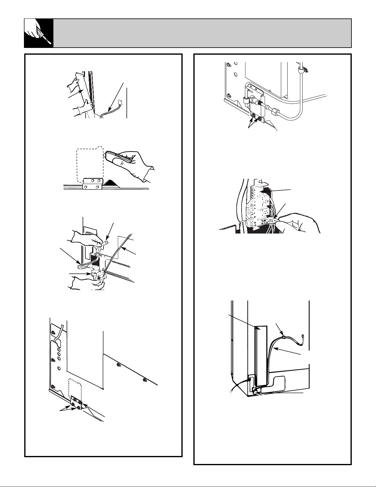
PREPARE THE BACK OFTHE REFRIGERATOR
e. Attach the water valve to the lower rail using
the hex screws removed from the mounting
plate. This will assure that the water valve is
electrically grounded.
f. Plug the water valve wire connector into the
terminal board at the points on the bottom right
position, marked “1” and “2” across from “A”
and “B.”
g. Re-install the vertical wire and tube cover. To
avoid pinching wires, carefully tuck the wires
inside the cover. Secure the cover by reusing all
the original screws.
h. Secure the 1/4 inch flexible plastic tubing to
the rear wall of the refrigerator cabinet using the
plastic stick-on clamp.
NOTE: The P-clamp is used to secure the
1/4 inch flexible copper tubing at the back
horizontal cover, using the existing cover screw.
(See Water Line Installation Instructions.)
INSTALL THE WATER VALVE.
a. Remove and save the 4 hex screws and the
vertical wire and tube cover from the back of the
refrigerator.
b. To access the water valve, cut along the
outline in the fiberboard cover using a utility
knife. Remove the fiberboard.
c. Thread the water valve wires through the
rectangular opening, taking care not to bend any
existing tubes.
d. Use a 1/4″ hex nut driver to remove the two
lower screws from the valve mounting plate and
discard the mounting plate.
Wire and
tube cover
1/4″ plastic
tubing
1/4″
plastic
tubing
Water
valve
wires
Water valve
wire connector
Water
valve
Wire and
tube cover
Plastic
stick-on
clamp
1/4″ flexible
plastic tubing
Water valve
Terminal
board
Water
valve wire
connector
8
Reuse hex screws to
mount water valve
Discard
mounting plate
Remove hex screws
and reuse to mount
water valve
9
WATER LINE INSTALLATION INSTRUCTIONS
WHAT YOU WILL NEED
A cold water supply is required for
automatic icemaker operation. Water
pressure must be between 20 and 120 p.s.i.
Copper tubing, 1/4″ O.D., should be used to
connect the refrigerator to the water supply. Do
not use plastic tubing or plastic fittings
because the connection between the water
supply and the refrigerator water valve inlet is
under constant water pressure. Also, certain
types of plastic tubing may become brittle with
age and crack, resulting in water leakage.
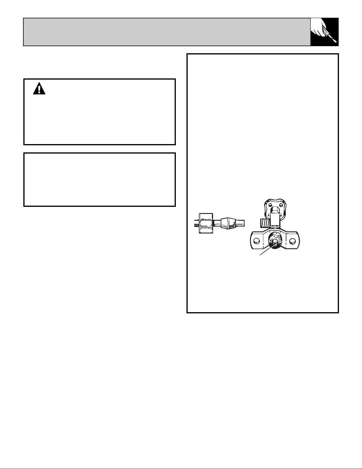
A shutoff valve should be connected to the
cold water line. The shutoff valve should have a
water inlet with a minimum inside diameter
of 5/32″ at the point of connection to the
COLD WATER LINE. A saddle-type shutoff
valve permitted by many local plumbing codes is
shown below.
Check your local plumbing codes before
choosing this type of valve. We recommend
using the saddle valve supplied with GE Water
Supply Kits WX8X2, WX8X3 and WX8X4.
NOTE: DO NOT USE A SELF-PIERCING
VALVE.
If you use your refrigerator before connecting
the water line, make sure the icemaker feeler
arm is kept in the STOP (up) position.
CAUTION:
• When using any electrical device (such as a
power drill) during installation, be sure the
device is insulated or wired in a manner to
prevent the hazard of electric shock.
• All installations must be in accordance with
local plumbing code requirements.
WARRANTY INFORMATION
This water line installation is not
warranted by the refrigerator or icemaker
manufacturer. Follow these instructions
carefully to minimize the risk of expensive
water damage.
(continued next page)
Min. 5/32″ dia. opening
Shutoff Valve
10
WATER LINE INSTALLATION INSTRUCTIONS
(continued)
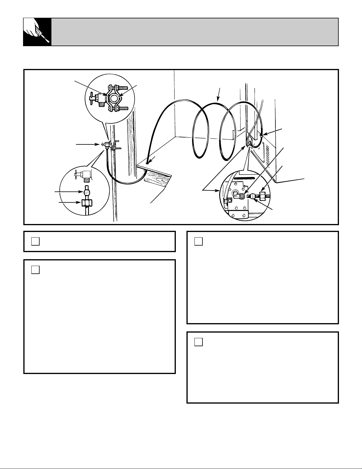
TYPICAL PLUMBING INSTALLATION WITH WATER SUPPLY KITS WX8X2, WX8X3 and WX8X4
SHUT OFF MAIN WATER SUPPLY.
1
INSTALL SHUTOFF VALVE ON NEAREST COLD
FREQUENTLY USED DRINKING WATER LINE.
a. Choose a location for the valve that is easily
accessible. It is best to connect into the side of a
vertical water pipe. When it is necessary to
connect into a horizontal water pipe, make the
connection to the top or side, rather than at the
bottom, to avoid drawing off any sediment from
the water pipe.
b. Drill a 1/4″ hole in one wall of the water pipe,
using a sharp bit. Remove any burrs resulting
from drilling the hole in the pipe.
c. Tighten the clamp screws until the sealing
washer begins to swell.
2
ROUTE COPPER TUBING BETWEEN
COLD WATER LINE AND REFRIGERATOR.
a. Route copper tubing where the temperature
remains above 35°F.
b. Then route the tubing through a hole drilled
in the floor (behind the refrigerator or adjacent
base cabinet) as close to the wall as possible. Be
sure there is sufficient extra tubing (about 8 feet
coiled into 3 turns of about 10 inches diameter)
to allow the refrigerator to move out from the
wall after installation.
3
CONNECT COPPER TUBING TO SHUTOFF
VALVE.
Place the compression nut and ferrule onto the
end of the tubing and connect to the shutoff
valve. Make sure the tubing is fully inserted into
the valve. Tighten the compression nut securely,
then pull on the tube to check for a secure
connection. DO NOT OVERTIGHTEN.
4
Sealing
washer
Shutoff valve
Ferrule
Cold water
pipe
Tubing coiled
Hole for tubing
P-clamp
Compression nut
Ferrule
Refrigerator
connection
Compression
nut
1/4″ Fitting
11
SET THE ICEMAKER FEELER ARM
TO THE ON (DOWN) POSITION.
The icemaker will not begin to operate until it
reaches its operating temperature of 15°F. or
below. It will then begin operation automatically.
8
CONNECT COPPER TUBING TO
REFRIGERATOR.
Before making connection to the
refrigerator, be sure refrigerator power
cord is not plugged into wall outlet.
a. Turn water on and flush out the tubing,
making certain that all foreign matter is
removed from the line.
b. Shut the water off after about 1 quart
of water has been flushed through the tubing.
NOTE: Some localities may have sand or other
foreign matter present in the water supply in
such quantities that they may, in time, collect in
the screen of the water valve attached to the
back of the refrigerator and tend to reduce the
water flow to the icemaker. Where such
conditions exist, we recommend that an
additional filter or strainer be installed in the line
near the refrigerator. If a screen type strainer is
used, it should be 80 mesh or finer.
c. Cut off the flared end of the copper tubing
and remove the flare nut from the tubing.
d. Remove the plastic cap from the water valve
and plastic tube assembly.
e. Connect copper tubing to the refrigerator
water valve. Place the 1/4″ compression nut and
ferrule onto the end of the tubing as shown on
page 10.
f. Insert the end of the copper tubing into the
water valve as far as possible. While holding the
tubing, tighten the fitting, then pull on the tube
to check for a secure connection. DO NOT
OVERTIGHTEN.
g. Secure the 1/4 inch flexible copper tubing
with the P-clamp at the back horizontal cover,
using the existing cover screw.
5
TURN ON WATER AND CHECK
ALL JOINTS FOR LEAKS.
Tighten fittings if required to stop leaks.
6
PLUG REFRIGERATOR POWER CORD INTO
APPROPRIATE ELECTRICAL OUTLET.
7
MOVE THE REFRIGERATOR BACK TO THE
WALL.
Arrange the coil of copper tubing so that it does
not vibrate against the back of the refrigerator
or against the wall. Make sure the copper tubing
does not get kinked.
9
NOTE:
The first few batches of cubes should be thrown
away, so that remaining impurities in the water
line will be flushed out.
Wire and
tube cover
Plastic
stick-on
clamp
1/4″ plastic
tubing
Water valve
1/4″ flexible
copper
tubing
P-clamp
Back
cover
screw
WHAT IS COVERED
FULL ONE-YEAR WARRANTY
For one year from date of original
purchase, we will provide, free of
charge, parts and service labor in
your home to repair or replace
any part of the automatic
icemaker
that fails because of a
manufacturing defect.
******************************
This warranty is extended to
the original purchaser and any
succeeding owner for products
purchased for ordinary home use
in the 48 mainland states, Hawaii
and Washington, D.C. In Alaska the
warranty is the same except that it
is LIMITED because you must pay
to ship the product to the service
shop or for the service technician’s
travel costs to your home.
All warranty service will be
provided by our Factory Service
Centers or by our authorized
Customer Care
®
servicers during
normal working hours.
Should your appliance need service,
during warranty period or beyond,
call 800-GE-CARES (800-432-2737).
WHAT IS NOT COVERED
• Service trips to your home to teach
you how to use the product.
Read your Use and Care
material.
If you then have any
questions about operating the
product, please contact your dealer
or our Consumer Affairs office at
the address below, or call, toll free:
GE Answer Center
®
800.626.2000
consumer information service
• Improper installation.
If you have an installation problem,
contact your dealer or installer.
You are responsible for providing
adequate electrical, plumbing and
other connecting facilities, including
the water line to the icemaker and
the water line installation.
• Replacement of house fuses or
resetting of circuit breakers.
• Failure of the product if it is used
for other than its intended purpose
or used commercially.
• Damage to product caused
by accident, fire, floods or acts
of God.
WARRANTOR IS
NOT
RESPONSIBLE FOR
CONSEQUENTIAL DAMAGES.
Some states do not allow the exclusion or limitation of incidental or consequential damages, so the above limitation or exclusion
may not apply to you. This warranty gives you specific legal rights, and you may also have other rights which vary from state to state.
To know what your legal rights are in your state, consult your local or state consumer affairs office or your state’s Attorney General.
Warrantor: General Electric Company
If further help is needed concerning this warranty, write:
Manager—Consumer Affairs, GE Appliances, Louisville, KY 40225
UK-KIT-3S
Part No. 162D1599P008
Pub No. 49-60081
1-00 JR
Printed in the United States
YOUR AUTOMATIC ICEMAKER
WARRANTY
Staple sales slip or cancelled check
here. Proof of original purchase date
is needed to obtain service
under warranty.
10527049