Loading ...
2
TEST THE UNIVERSAL RECEIVER FOR DAMAGE
You may need to replace the pre-installed universal receiver
(model 850LM). To test the universal receiver for damage:
1. Disconnect power to the operator.
2. Disconnect the universal receiver from the operator.
3. Configure a digital voltmeter to measure resistance.
4. Connect the negative or black lead of the voltmeter to the “F”
connector used to ground the universal receiver antenna.
5. Connect the positive or red lead of the voltmeter to:
a. The + power input of the universal receiver. If the meter
reads (0Ω), there is a short indicating the universal receiver
is damaged. Replace the universal receiver.
b. The - power input of the universal receiver. If the meter
reads (0Ω), there is a short indicating the universal receiver
is damaged. Replace the universal receiver.
NOTE: Don’t confuse 0Ω with ∞Ω.
6. If the voltmeter does not indicate a short, the universal
receiver can be used.
INSTALL THE ISOLATION KIT
To install the isolation kit:
1. Disconnect power to the operator.
2. Remove all accessories from the operator.
3. Locate the chassis-mounted “F” connector (where the coax
antenna passes through the operator chassis). Location
varies depending on the operator, refer to the owner’s
manual.
4. Disconnect the coax cables from both sides of the “F”
connector.
5. Remove the “F” connector and the mounting hardware. Set
aside for reinstallation.
6. Drill out the hole using a 1/2" drill bit.
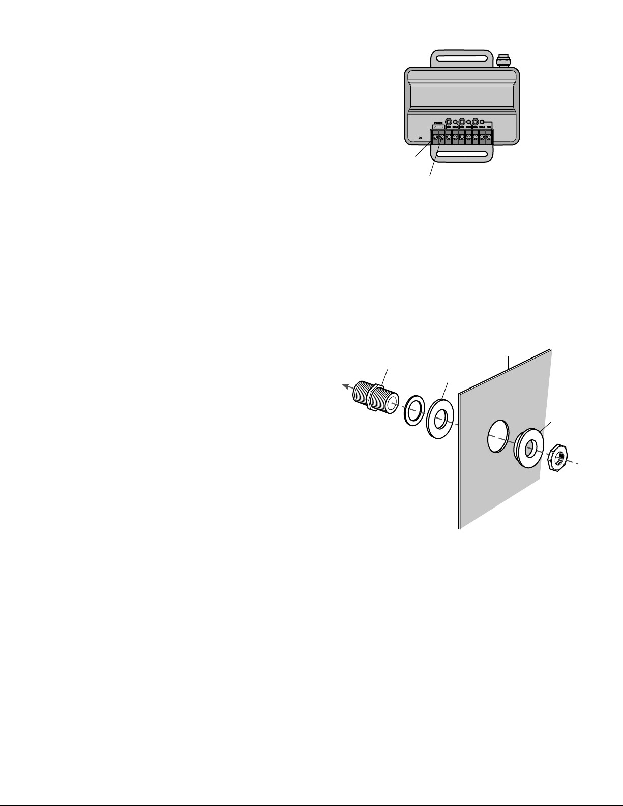
7. Reinstall the “F” connector to the chassis. Insert the isolation
washers between the operator chassis and the other
hardware. The shoulder washer should go on the inside of the
operator. The flat washer should go on the outside of the
operator. See illustration for assembly order.
8. Reconnect the coax cables to the “F” connector.
9. Connect the antenna ground to the chassis.
10. Connect all other accessories according to the instructions
that came with them.
11. Restore power and test the operator.
Chassis
Nylon flat washer
“F” connector
To antenna
Nylon
shoulder
washer
(+) power
input
(-) power
input
Loading ...
Loading ...
Loading ...