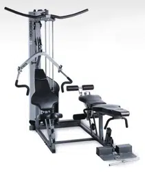
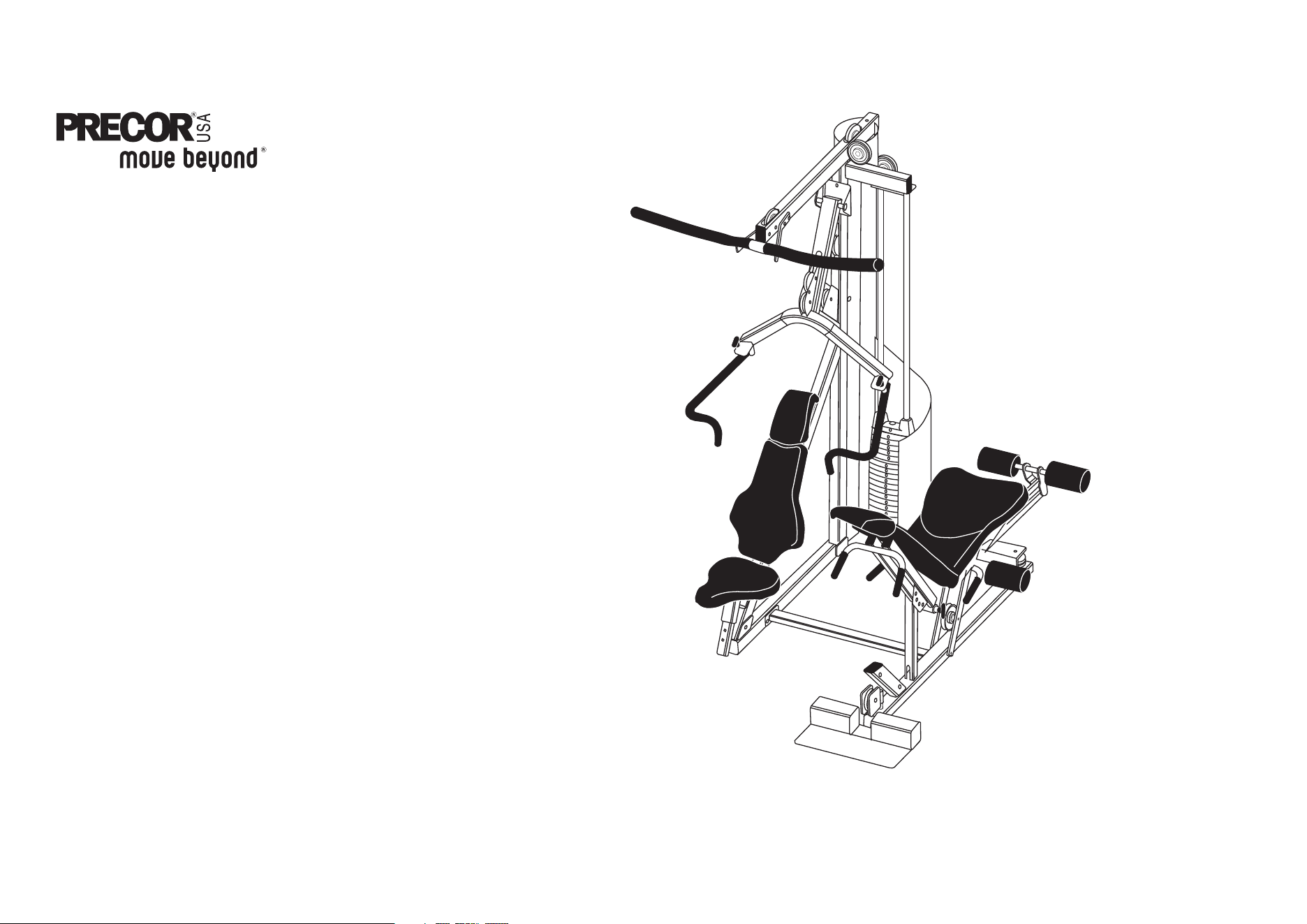
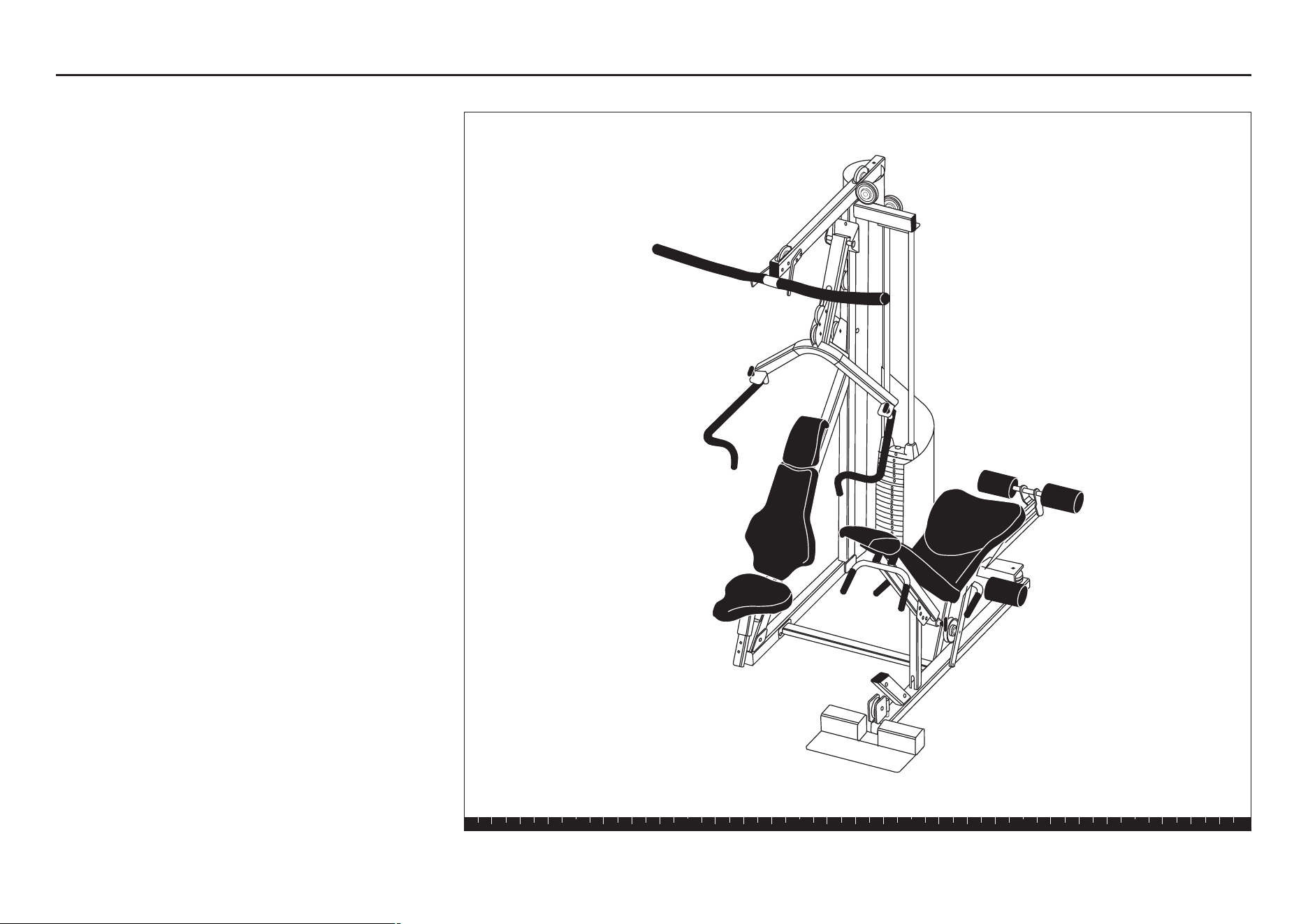
Assembly and Maintenance Guide
S3.25
Strength-Training
Fitness Equipment

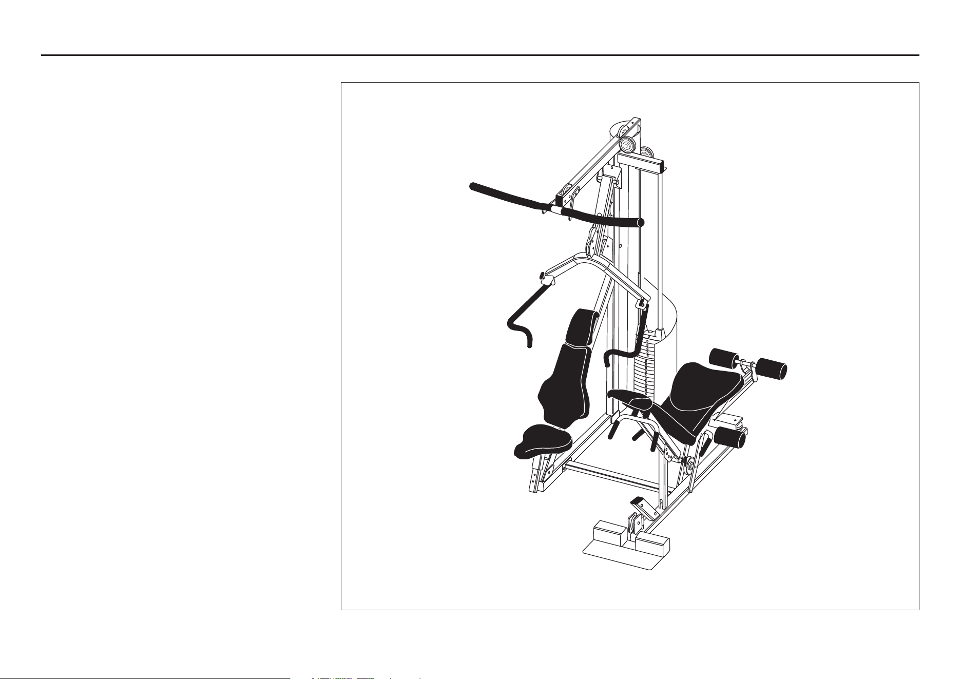
S3.25 Assembly and Maintenance Guide
page 2
IMPORTANT SAFETY INSTRUCTIONS
Important Safety Instructions
Important Safety Instructions
Before beginning any fitness program, you should
obtain a complete physical examination from your
physician.
Il est conseillé de subir un examen médical complet
avant d’entreprendre tout programme d’exercise. Si
vous avez des étourdissements ou des faiblesses,
arrêtez les exercices immédiatement.
When using exercise equipment, you should always
take basic precautions, including the following:
• Read all instructions before using the S3.25
equipment. These instructions are written to
ensure your safety and to protect the unit.
• Do not allow children on or near the equipment.
• Use the equipment only for its intended purpose
as described in this guide. Do not use accessory
attachments that are not recommended by the
manufacturer: such attachments might cause
injuries.
• Wear proper exercise clothing and shoes for your
workout—no loose clothing.
• Use care when getting on or off the unit.
• Do not overexert yourself or work to
exhaustion.
• If you feel any pain or abnormal symptoms,
stop your workout immediately and consult
your physician.
• Never operate the unit when it has been dropped or
damaged. Return the equipment to a service center
for examination and repair.
• Never drop or insert objects into any opening in the
equipment. Keep hands away from moving parts.
• Always check the unit and its cables before each
use. Make sure that all fasteners and cables are
secure and in good working condition.
• Do not use the equipment outdoors.
Personal Safety During Assembly
• It is strongly recommended that a qualified dealer
assemble the equipment.
Assistance is required.
• Read each step in the assembly instructions and
follow the steps in sequence. Do not skip ahead. If
you skip ahead, you may learn later that you have
to disassemble components and that you may
have damaged the equipment.
• Assemble and operate the S3.25 on a solid, level
surface. Locate the unit a few feet from walls or
furniture to provide easy access.
The S3.25 is designed for your enjoyment. By following
these precautions and using common sense, you will
have many safe and pleasurable hours of healthful
exercise with your Precor equipment.
Obtaining Service
Do not attempt to service the S3.25 yourself
except for the maintenance tasks described
in this guide. This unit does not contain any
user-serviceable parts.
For information about product operation or
service, check out the Precor web site at
www.precor.com or contact an authorized
Precor dealer or a Precor factory-authorized
service company. To locate the dealer or service
person nearest you, call 1-800-347-4404.
If you call or e-mail Customer Support, have
the serial number and part numbers available.
You can find the serial number printed on a
label on the back of the two braces on the
base of the Main Upright. For future
reference, write the serial number in the
space below.
Serial number: _____________

S3.25 Assembly and Maintenance Guide
page 3
Table of Contents
Table of Contents
1
2
3
Important Safety Instructions ....................................................................... 2
Personal Safety During Assembly ............................................................................................ 2
Obtaining Service ..................................................................................................................... 2
Before You Begin ........................................................................................... 5
Unpacking the Equipment ........................................................................................................ 5
Optional Equipment .................................................................................................................. 5
Preparations for Assembly ........................................................................... 6
Required Tools .......................................................................................................................... 6
Installation Requirements ......................................................................................................... 6
Assembly Tips ......................................................................................................................... 6
Assembly Instructions .................................................................................. 7
Open Box 1 .............................................................................................................................. 8
1. Attach Rear Upright to Main Upright .............................................................................. 9
2. Attach Chest Press Base .............................................................................................. 10
Open Box 2 .............................................................................................................................. 11
3. Assemble Leg Curl Seat Extension ............................................................................... 12
4. Attach Rotating Arm and Handles.................................................................................. 13
5. Attach Roller Pads ......................................................................................................... 14
6. Assemble Leg Curl Seat ................................................................................................ 15
Open Box 3 .............................................................................................................................. 17
7. Assemble Chest Press Seat ......................................................................................... 18
8. Attach Press Arm Assembly ......................................................................................... 19
9. Attach Handlebars ......................................................................................................... 20
10. Assemble Chest Press Seat ......................................................................................... 21

S3.25 Assembly and Maintenance Guide
page 4
Table of Contents
Open Box 4 .............................................................................................................................. 22
11. Assemble Weight Stack ................................................................................................ 23
12. Feed Upper Cable .......................................................................................................... 24
13. Attach Lat Bar Holders .................................................................................................. 25
14. Feed Cable From Cable Tree .......................................................................................... 26
15. Attach Leg Curl Cables to Lower Pulley Bracket ............................................................ 29
16. Attach Leg Curl Cables to Seat Upright ......................................................................... 30
17. Feed Top Cable 44376-102 ............................................................................................. 31
18. Feed Bottom Cable 44375-103 ...................................................................................... 32
19. Attach Surgical Tubing to Top Beam ............................................................................... 33
20. Attach Leg Curl Cables to Cable Tree............................................................................. 34
21. Attach Accessories ....................................................................................................... 35
22. Attach Shrouds ............................................................................................................. 36
Adjustments and Maintenance ..................................................................... 37
1. Cable Adjustments .............................................................................................................37
2. Selector Stem Adjustments ................................................................................................ 38
Forward Angle Adjustment .................................................................................................. 38
Backward Angle Adjustment ............................................................................................... 39
Side-to-Side Vertical Adjustment......................................................................................... 40
3. Maintenance ....................................................................................................................... 40
Warranty Registration ............................................................................................................... 41
Warranty Card and Specifications ................................................................................ Back cover
4
S3.25 Assembly and Maintenance Guide
page 5
1
Before You Begin
Before You Begin
Thank you for purchasing the S3.25. This unit is part
of the Pacific Fitness line of quality strength training
machines, which let you target specific muscle groups
to achieve better muscle tone and overall body
conditioning. To maximize your use of the equipment,
please study this guide thoroughly.
Unpacking the Equipment
The S3.25 is carefully tested and inspected before
shipment. Pacific Fitness ships the unit in several
pieces that require assembly. Ask for assistance during
the assembly process.
• Review the
Installation Requirements
found on the
next page.
• When instructed to open a box, carefully unpack
the pieces and lay them on the floor near the place
where you plan to use the equipment.
Be careful to open boxes and assemble components in
the sequence presented in this guide.
If any items are missing, contact the dealer from whom
you purchased the unit or call 1-800-347-4404 for the
dealer nearest you.
Optional Equipment
Optional equipment that you can purchase through
your dealer includes the 250-lb Weight Stack and the
Leg Press.
Note: If you have also purchased the Leg Press
Option and are assembling it simultaneously, specific
directions are included to reduce your setup time.

S3.25 Assembly and Maintenance Guide
page 6
2
Preparations
Preparations
CAUTION: To set up this unit, you will need
assistance. Do not attempt assembly by yourself.
You must review and follow the instructions in this
guide. If you do not assemble and use the S3.25
according to these guidelines, you could void the
Pacific Fitness limited warranty (see back cover).
Required Tools
Tools that you must obtain before assembling the
unit include:
❏ ⁹⁄₁₆-inch socket wrench
❏ ¾-inch socket wrench
❏ ⁹⁄₁₆-inch box-end wrench
❏ ¾-inch box-end wrench
❏ Standard set of metric Allen wrenches
❏ Two adjustable pliers or crescent wrenches
❏ Measuring tape
❏ Wire tie cutter (cuts plastic tie wraps)
❏ Rubber mallet
❏ Step stool
Installation Requirements
Follow these installation requirements when
assembling the unit:
• Fill out and mail the limited warranty card.
The warranty card is found on the back cover of
this guide.
• Set up the S3.25 on a solid, flat surface. A
smooth, flat surface under the unit helps keep it
level. A level unit has fewer malfunctions.
• Provide ample space around the machine.
Open space around the machine allows for
easier access.
• Insert all bolts in the same direction. For
aesthetic purposes, insert all the bolts in the
same direction unless specified (in text or
illustrations) to do otherwise.
• Leave room for adjustments. Tighten fasteners
such as bolts, nuts, and screws so the unit is
stable, but leave room for adjustments. Do not fully
tighten fasteners until instructed in the assembly
steps to do so.
Assembly Tips
• Read all caution notes on each page before
completing that step.
• While you may be able to assemble the S3.25
using the illustrations only, important safety notes
and other tips are included in the text.
• A 6-inch scale is provided at the bottom of every
assembly instruction page. Use this scale to
identify the correct size bolts and spacers. The
head of a bolt is not used in measuring the length
of a bolt.
Note: A few of the bolts used to assemble the
S3.25 are longer than 6 inches. You may want to
use a measuring tape to accurately identify the
correct sizes.
To find out the length of a particular bolt, measure
its shank (the long, narrow part beneath the head).
Refer to the following diagram:
Bolt head
Bolt threads
Shank
To determine the
length of a bolt,
measure its shank.
• Some pieces have extra holes that you will not use.
Use only those holes indicated in the instructions
and illustrations.
S3.25 Assembly and Maintenance Guide
page 7
1 2 3 4 5 6
3
Assembly
Instructions
Assembly Instructions
Assembly of the S3.25 takes professional installers
about 1.5 hours to complete. If this is the first time
you have assembled this type of equipment, plan on
significantly more time.
Professional installers are highly recommended!
However, if you acquire the appropriate tools, obtain
assistance, and follow the assembly steps sequentially,
the process will take time, but is fairly easy.
CAUTION: Obtain assistance! Do not attempt to
assemble the S3.25 by yourself. Review the
Installation Requirements
on page 6 before
proceeding with the following steps.
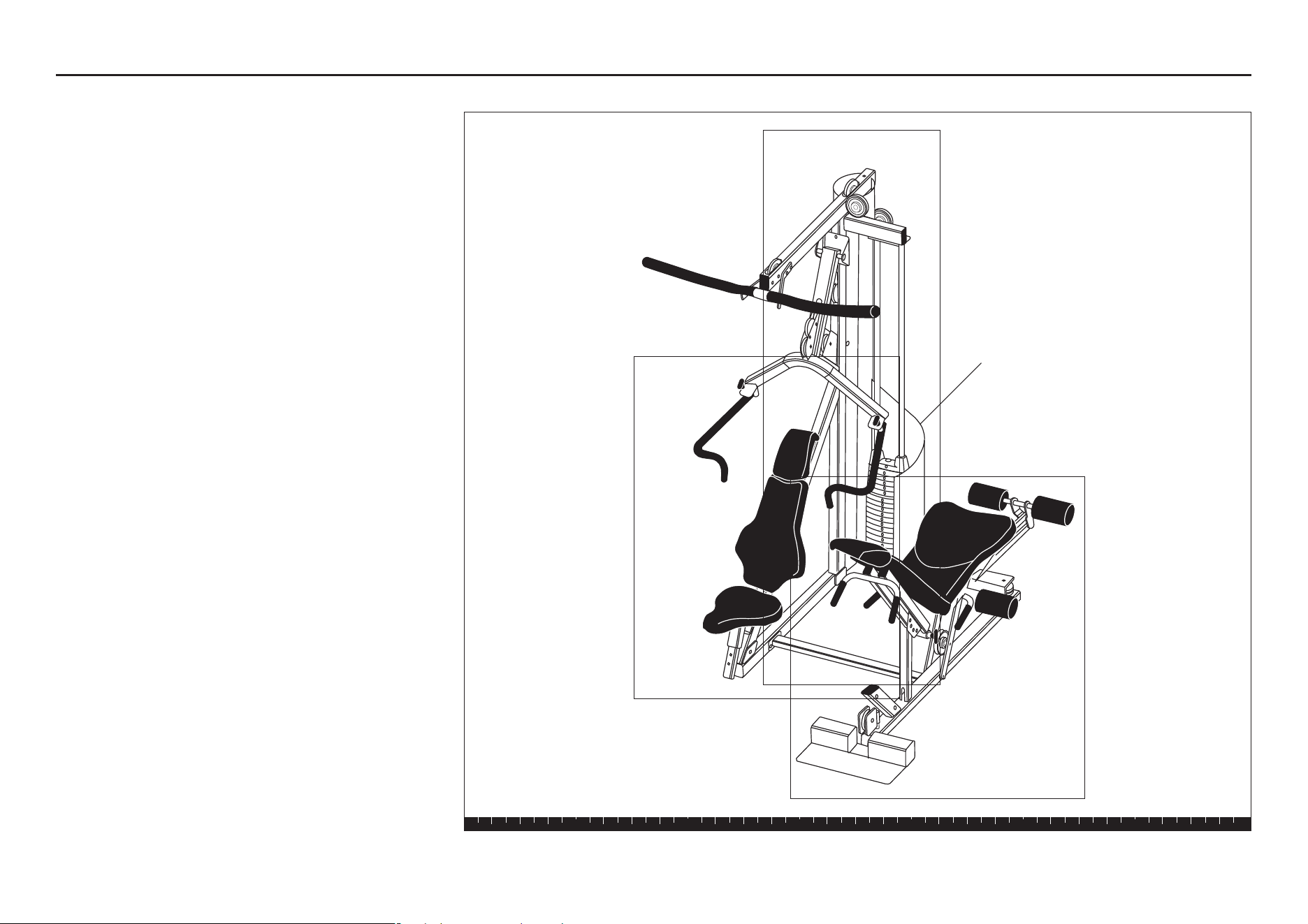
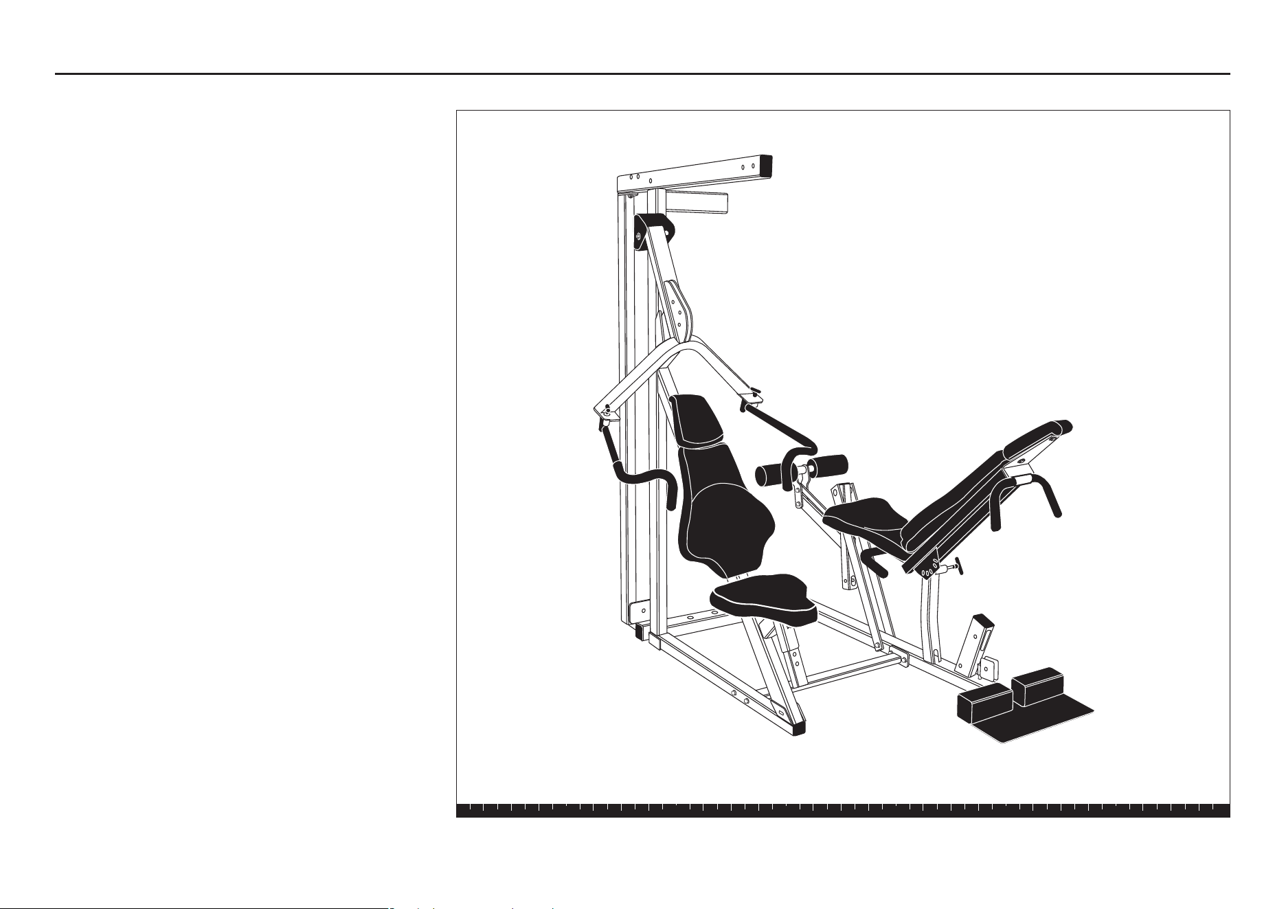
The S3.25 comes in four boxes. (See the diagram at
the right.)
Be careful to open boxes and assemble components in
the sequence presented in this guide.
Note: With so many assembled parts, proper
alignment and adjustment is critical. While tightening
the nuts and bolts, be sure to leave room for
adjustments.
Do not fully tighten bolts until
instructed to do so.
Box 1 - Main Structure
Box 3 - Chest
Press
Box 4 - Shrouds
Box 2 - Leg Curl
S3.25 Assembly and Maintenance Guide
page 8
1 2 3 4 5 6
Open Box 1
Open Box 1
Use tie cutters to open the box.
The illustration shows how the S3.25 will look after you
complete this section.
Note: Some items in these boxes may not be needed
until later in the assembly process.
Important: Only use fasteners in bags labeled S3.25.
Discard all fasteners in bags labeled S3.45.
S3.25 Assembly and Maintenance Guide
page 9
1 2 3 4 5 6
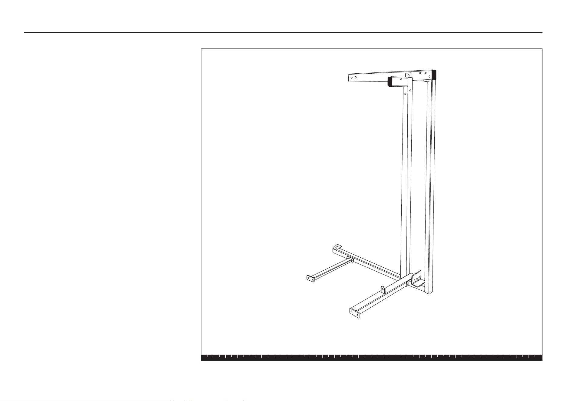
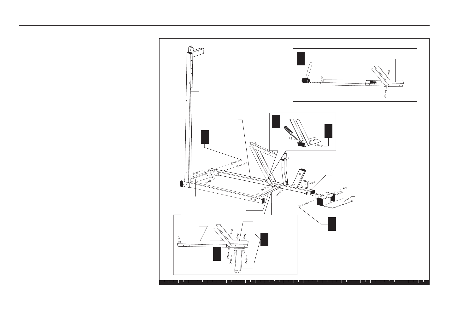
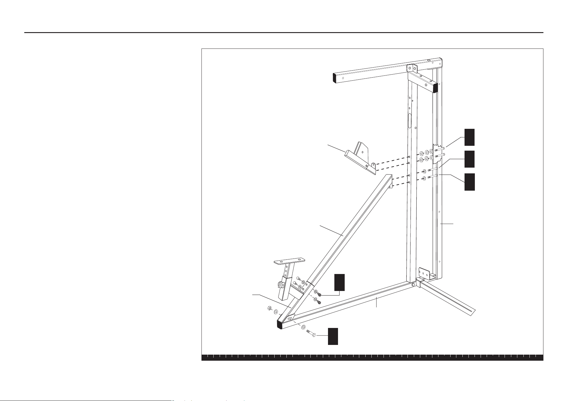
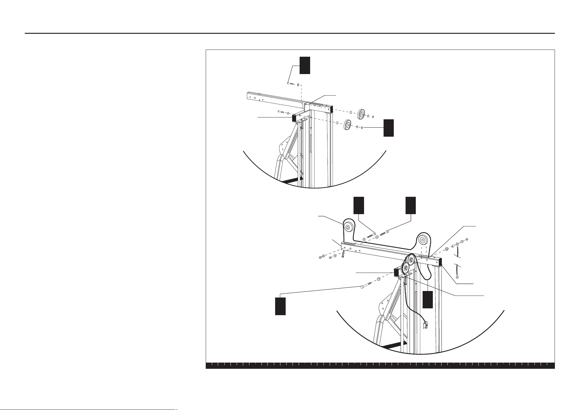
Step 1. Attach Rear Upright to Main Upright
1. Attach Rear Upright to
Main Upright
Begin the assembly by placing the Rear Upright and
Main Upright on the floor.
A. Attach the Rear Upright through the Main Upright
Base to the Main Upright using
two 3¼-inch bolts
four washers
two locknuts
Finger tighten.
B. Attach the Top Beam to the Rear Upright using
one 4-inch bolt
two washers
one locknut
Finger tighten.
C. Attach the Top Beam to the Main Upright using
one 3-inch bolt
two washers
one locknut
Finger tighten.
D. With someone helping you, lift the structure into
position. Place the structure where you intend to
keep it permanently.
2 - 3¼" bolts
4 - washers
2 - locknuts
Main Upright Base
A
Rear Upright
Main Upright
Top Beam
1 - 3" bolt
2 - washers
1 - locknut
C
1 - 4" bolt
2 - washers
1 - locknut
B
S3.25 Assembly and Maintenance Guide
page 10
1 2 3 4 5 6
2. Attach Chest Press Base
A. Attach the Chest Press Base to the Main Upright
using
one 3¼-inch bolt
two washers
one locknut
Finger tighten.
B. Attach the Floor Base to the Chest Press Base
using
two 3-inch bolts
four washers
two locknuts
Finger tighten.
If any parts remain, set them to the side for future
steps.
Step 2. Attach Chest Press Base
1 - 3¼" bolt
2 - washers
1 - locknut
A
Main Upright Base
Chest Press Base
Main Upright
B
2 - 3" bolts
4 - washers
2 - locknuts
Floor Base
S3.25 Assembly and Maintenance Guide
page 11
1 2 3 4 5 6
Open Box 2
Use tie cutters to open the box.
The illustration shows how the S3.25 will look after you
complete this section.
Note: Some items in these boxes may not be needed
until later in the assembly process.
Open Box 2
S3.25 Assembly and Maintenance Guide
page 12
1 2 3 4 5 6
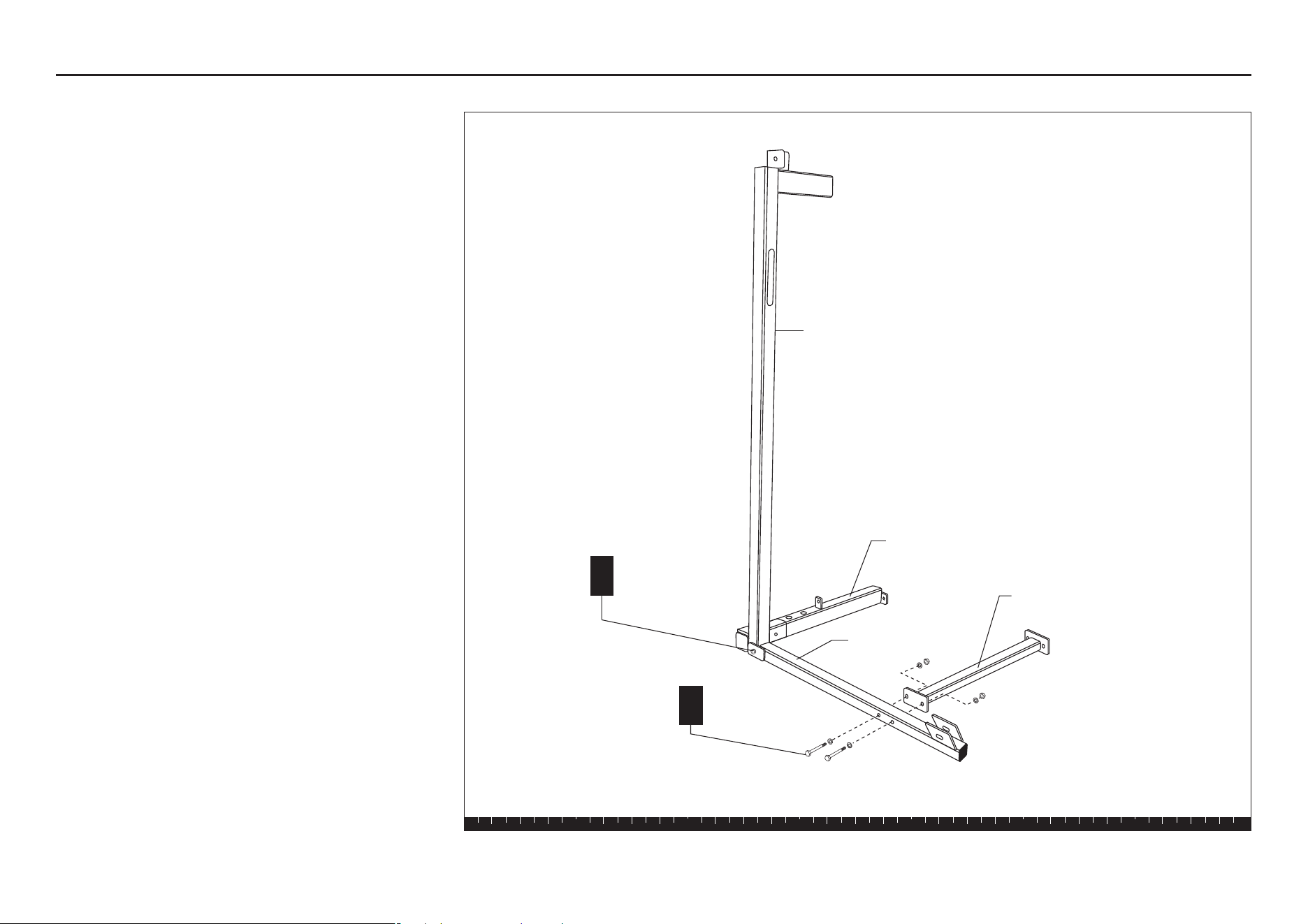
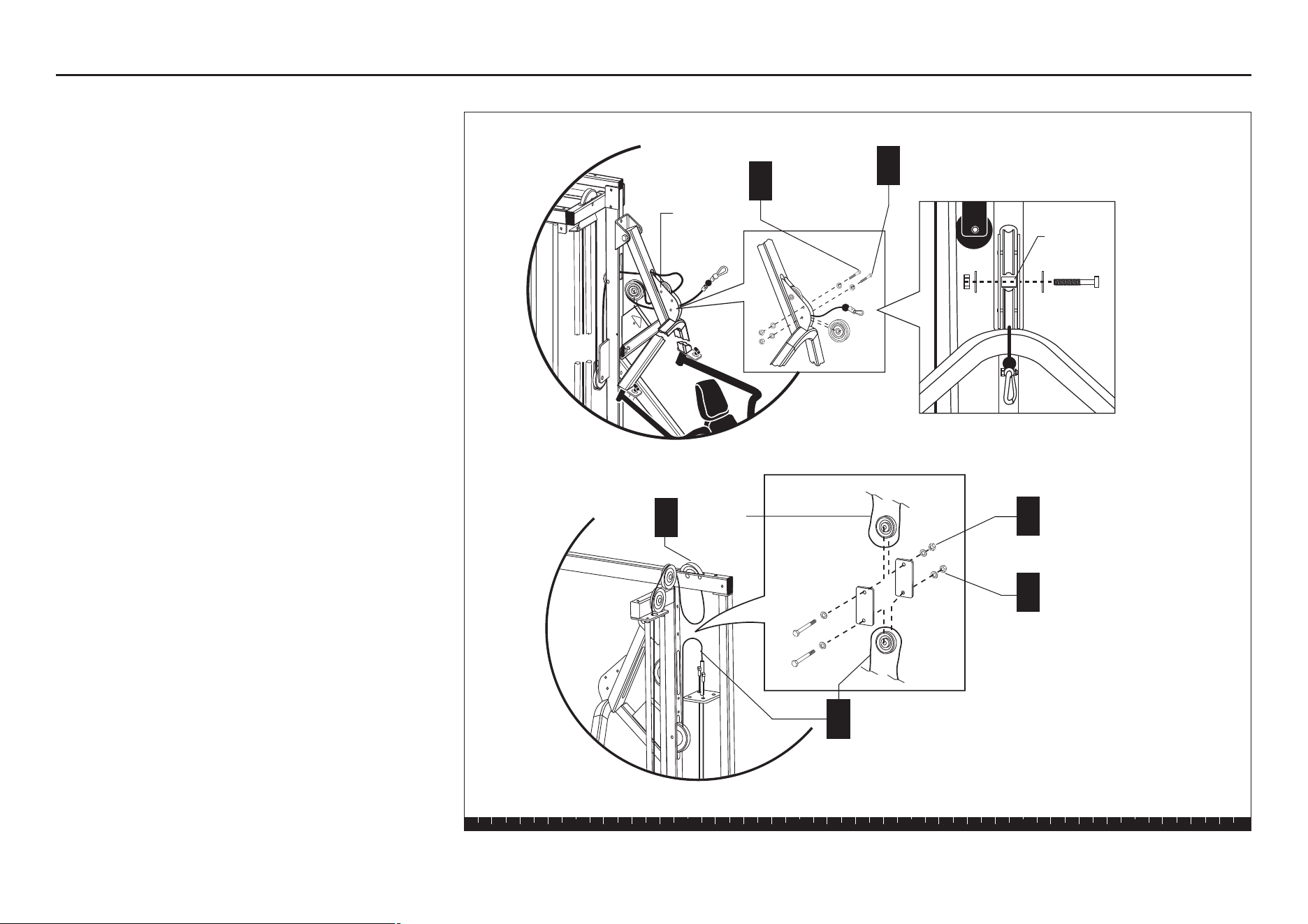
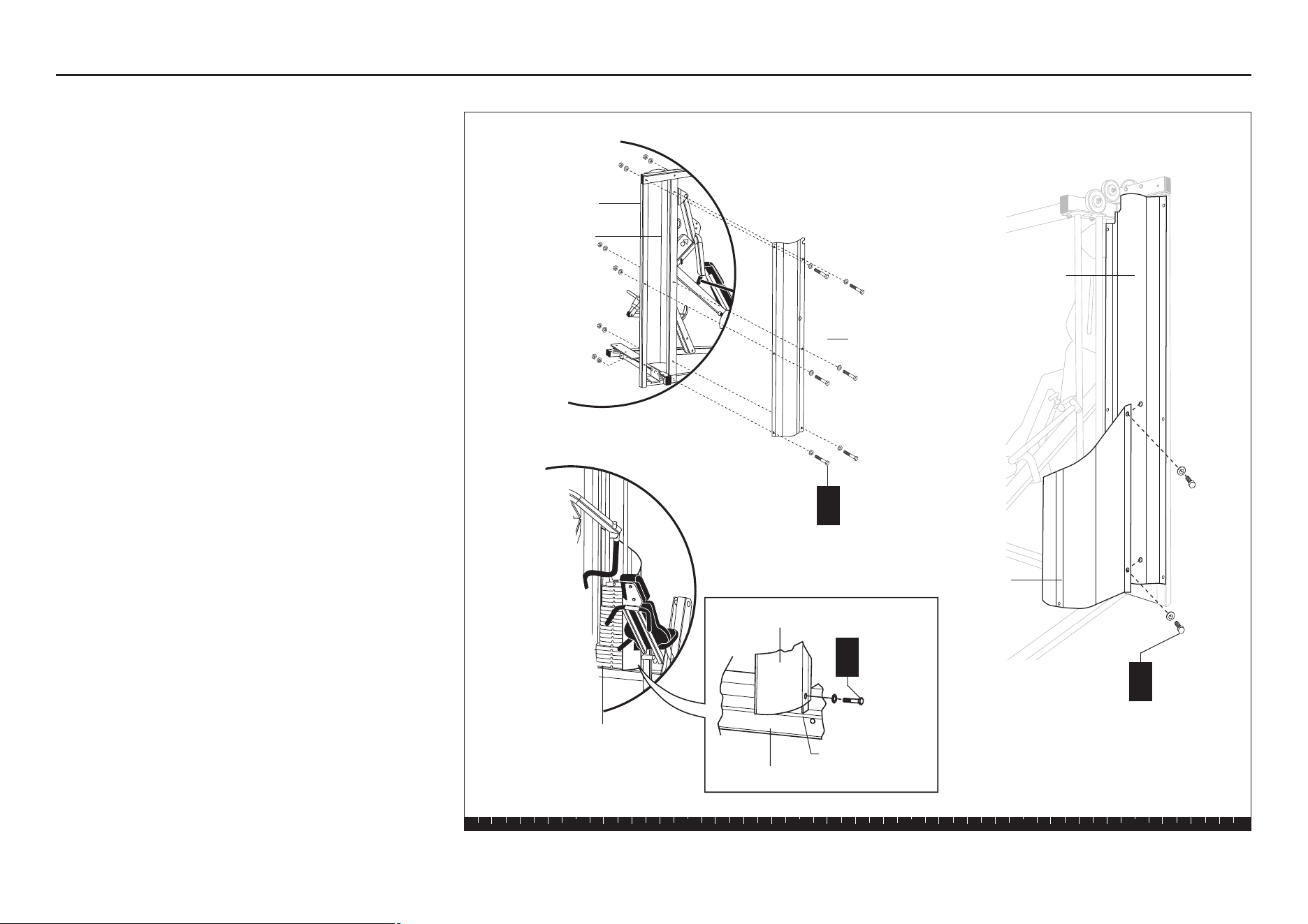
3. Assemble Leg Curl Seat
Extension
A. Use a flathead screwdriver to remove the black
end cap on the Leg Curl Seat Upright.
B. Detach the bolts at the bottom of the Upright Flats.
C. Insert the Leg Curl Seat Extension into the Leg
Curl Seat Upright, using a mallet, if necessary.
Cover the end cap with a piece of scrap wood to
protect the end cap from damage.
D. Attach the Leg Curl Seat Extension, Leg Curl Seat
Upright, and Floor Brace using
four ¾-inch bolts
four washers
Finger tighten.
E. Reattach the Upright Flats using its bolt, washers,
and locknut. Finger tighten.
F. Attach the Seat Extension to the Main Upright
Base using
two 4-inch bolts
four washers
two locknuts
Finger tighten.
G. Attach the Calf Block to the Seat Upright using
one 4¼-inch bolt
two washers
one locknut
H. Wrench tighten all bolts from this step.
Step 3. Assemble Leg Curl Seat Extension
F
2 - 4" bolts
4 - washers
2 - locknuts
D
4 - ¾" bolts
4 - washers
Leg Curl
Seat Upright
Main Upright
Base
B
C
G
1 - 4¼" bolt
2 - washers
1 - locknut
Calf Block
Floor Brace
Floor Brace
Main Upright
Seat Extension
Leg Curl Seat Extension
Leg Curl Seat Upright
E
A
Leg Curl Seat
Extension
Leg Curl Seat
Upright
S3.25 Assembly and Maintenance Guide
page 13
1 2 3 4 5 6
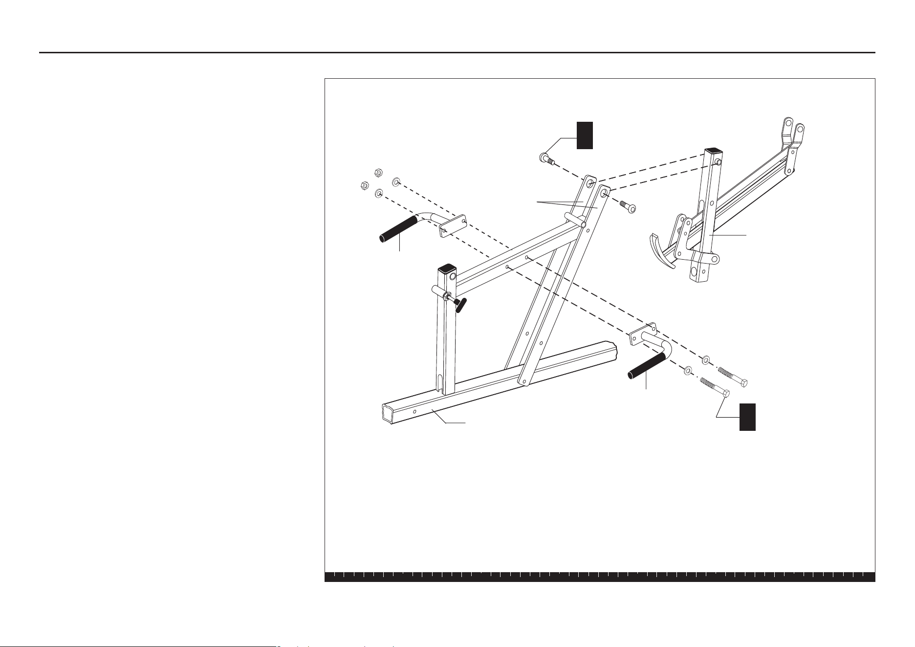
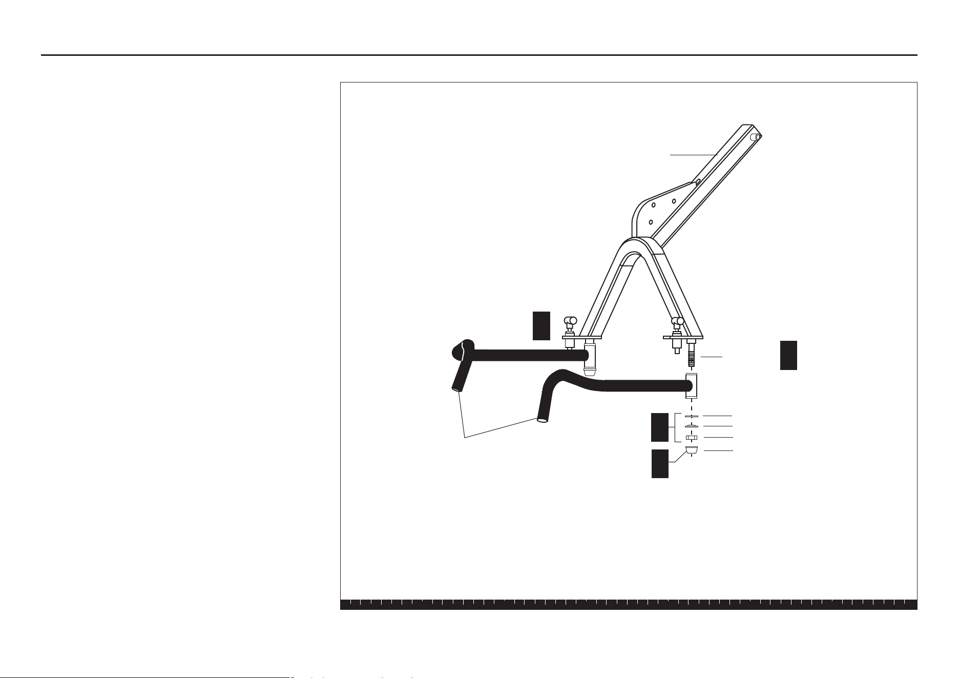
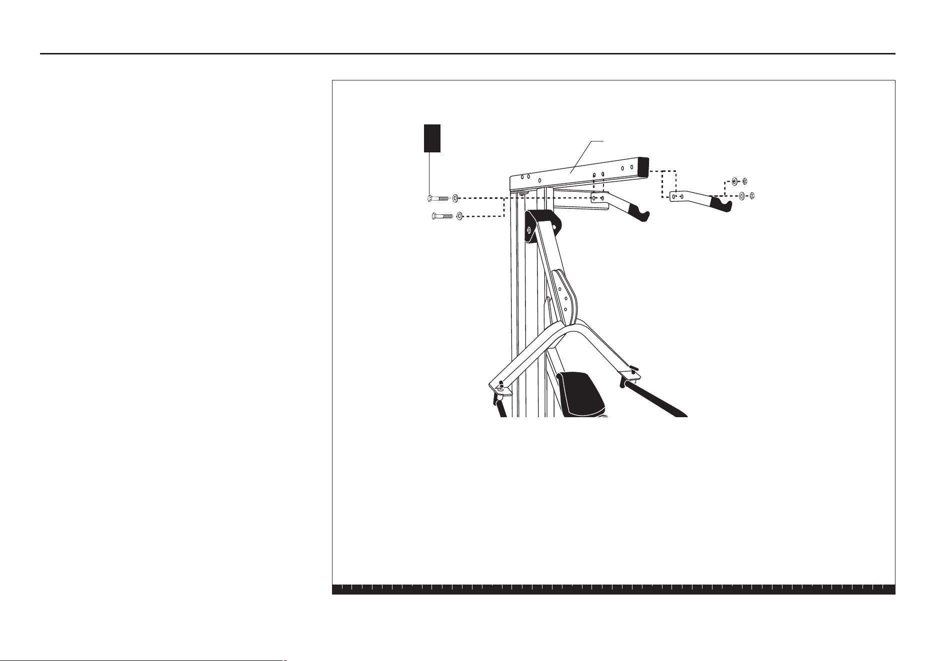
4. Attach Rotating Arm and
Handles
A. Attach the Rotating Arm to the Upright Flats using
two ¾-inch buttonhead bolts
Tighten with 6-mm Allen wrench.
B. Attach the Handles to the Seat Upright using
two 3¼-inch bolts
four washers
two locknuts
Wrench tighten.
Step 4. Attach Rotating Arm and Handles
A
2 - ¾" buttonhead bolts
B
2 - 3¼" bolts
4 - washers
2 - locknuts
Upright Flats
Handle
Seat Upright
Rotating Arm
Handle
S3.25 Assembly and Maintenance Guide
page 14
1 2 3 4 5 6
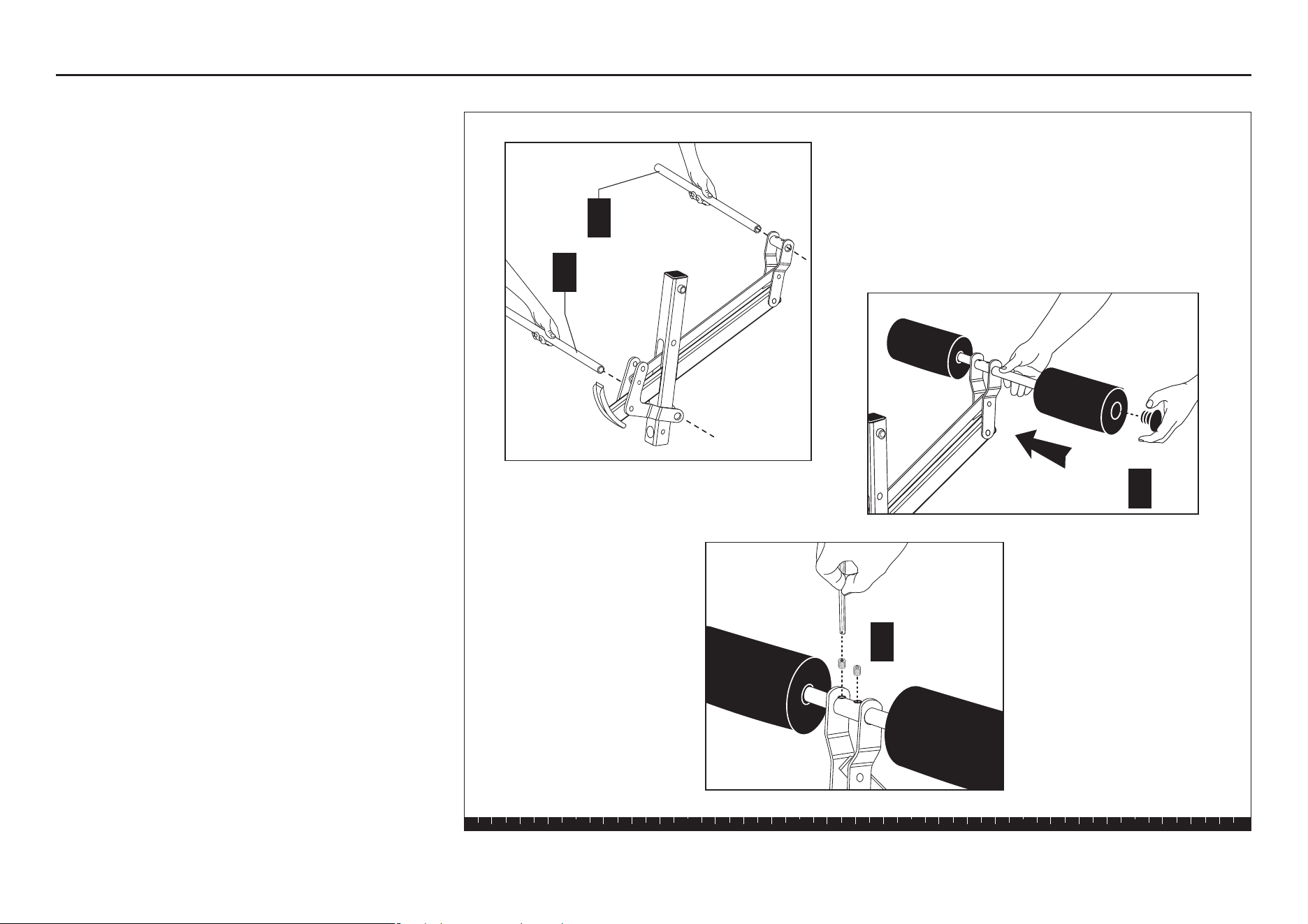
5. Attach Roller Pads
A. Insert the Leg Curl Roller Pad Rod.
B. Slide the Leg Curl Roller Pads on the Rod. Center
the Pads on the Rod. Insert End Caps into the end
of the Rod.
C. Secure the Rod in place from below using two hex
set screws.
D. Repeat steps A through C for the Leg Extension
Roller.
Step 5. Attach Roller Pads
A
B
Leg
Extension
Roller Pad
Rod
Leg Curl
Roller
Pad Rod
C
2 - hex set
screws
D
S3.25 Assembly and Maintenance Guide
page 15
1 2 3 4 5 6
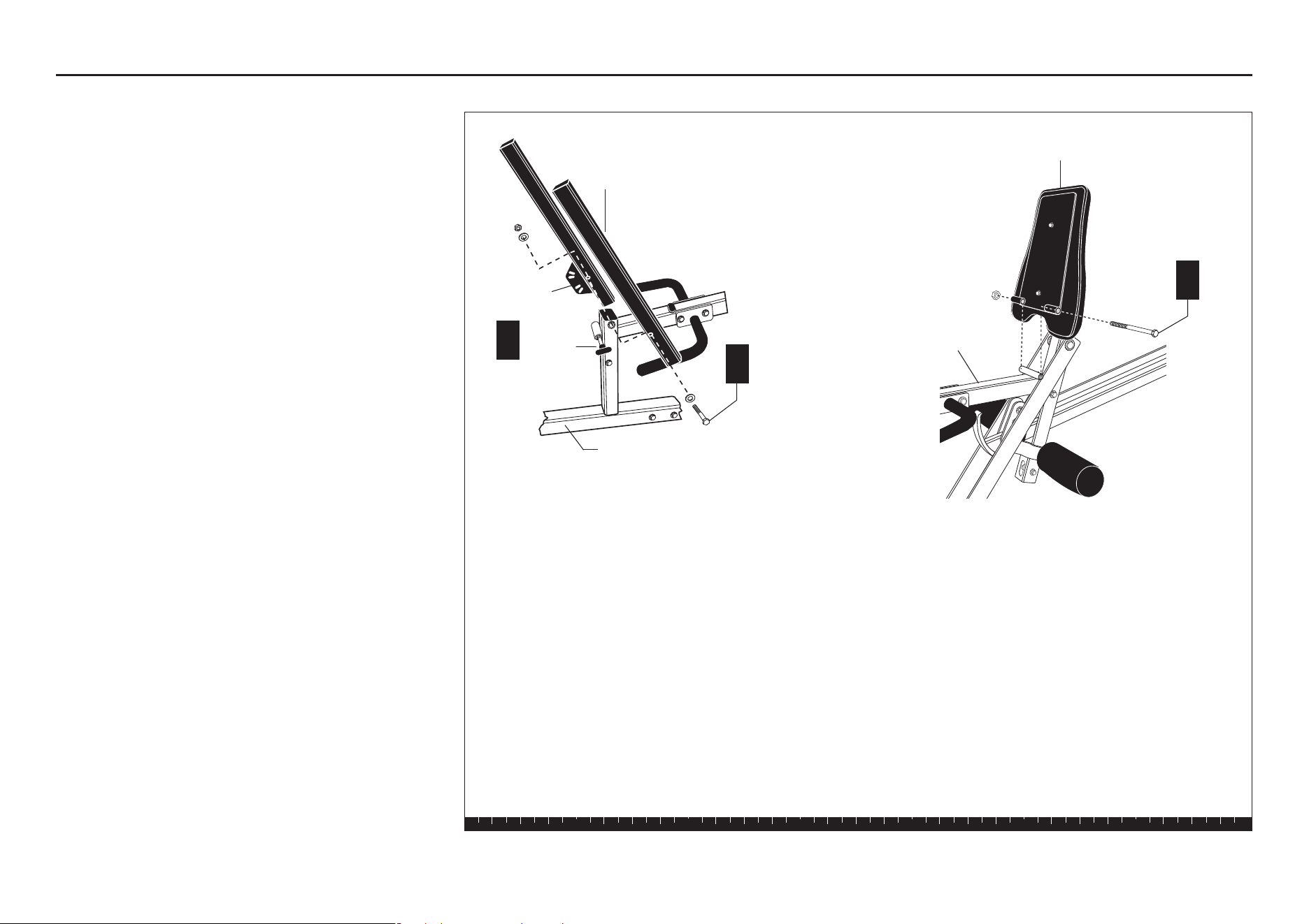
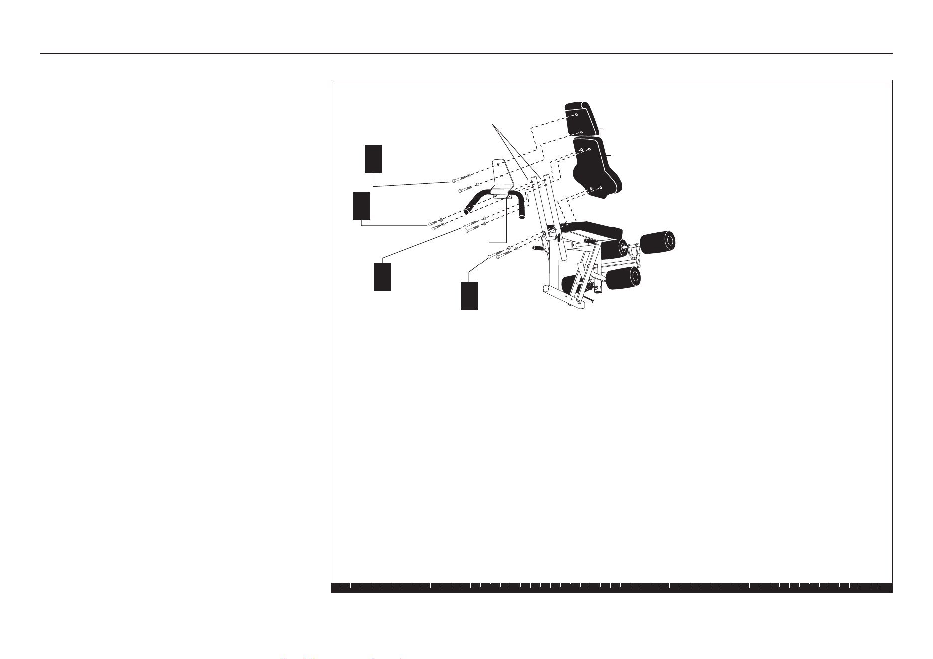
6. Assemble Leg Curl Seat
A. Attach the Backpad Support Tubes to the Seat
Upright using
one 5½-inch bolt
two ½-inch washers
one ½-inch locknut
Note: The tube with the Selector Pivot Flat is
nearest the Weight Stack. Also, the hole in the
other support tube is positioned closest to the
Backpad Pop Pin, as shown.
Wrench tighten, and then loosen until the support
tube can fall freely without wobbling.
CAUTION: Keep your hands clear to avoid
injury when the support tube falls.
B. Align the Selector Pivot Flat with the Backpad Pop Pin.
C. Attach the Seat Pad to the Seat Upright using
one 7-inch bolt
one ½-inch locknut
Finger tighten.
Step 6. Assemble Leg Curl Seat
A
C
Seat Upright
1 - 7" bolt
1 - ½" locknut
Seat Pad
1 - 5½" bolt
2 - ½" washers
1 - ½" locknut
Backpad Support
Tubes
Seat Upright
Selector
Pivot Flat
Backpad
Pop Pin
B
S3.25 Assembly and Maintenance Guide
page 16
1 2 3 4 5 6
D. Attach the lower section of the Backpad to the
lower hole of the right Backpad Support Tube using
two 3-inch bolt
two washers
Finger tighten.
E. Attach the Leg Curl Handle to the holes at the top of
the Backpad Support Tubes using
two 1-inch bolts
two washers
F. Attach the Backpad Support Tubes to the top of the
Backpad using
two 3-inch bolts
two washers
G. Attach the top portion of the Leg Curl Handle to the
holes at the top and bottom of the Headrest using
two 1¼-inch bolts
two washers
Note: The Handles should point down when fastened.
H. Wrench tighten all bolts from this step.
If any parts remain, set off to the side for future steps.
Step 6. Assemble Leg Curl Seat, Continued
D
G
2 - 1¼" bolts
2 - washers
2 - 3" bolt
2 - washers
Leg Curl
Handle
Backpad
Backpad Support
Tubes
Headrest
E
2 - 1" bolts
2 - washers
F
2 - 3" bolts
2 - washers
S3.25 Assembly and Maintenance Guide
page 17
1 2 3 4 5 6
Open Box 3
Use tie cutters to open the box.
The diagram shows how the S3.25 will look after you
complete this section.
Note: Some items in these boxes may not be needed
until later in the assembly process.
Open Box 3
S3.25 Assembly and Maintenance Guide
page 18
1 2 3 4 5 6
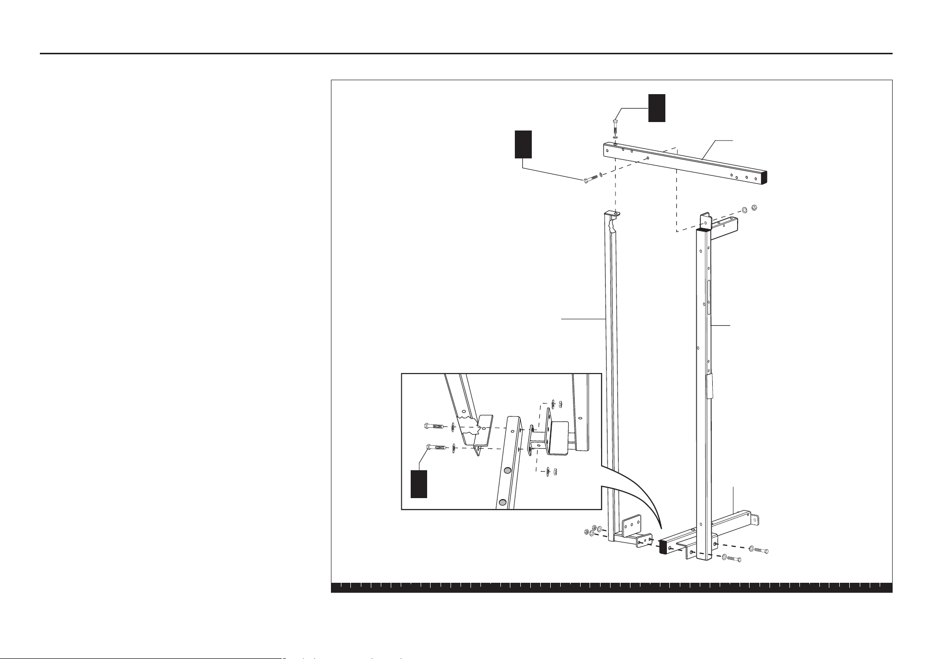
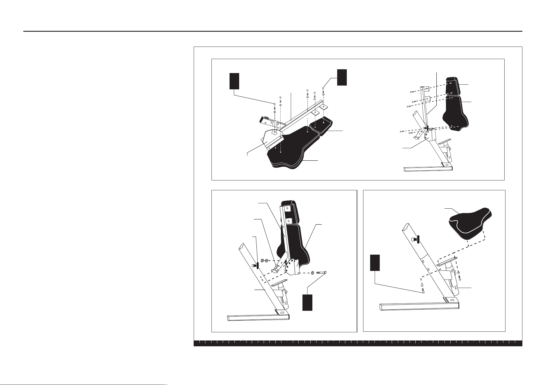
7. Assemble Chest Press Seat
A. Attach the Chest Press Upright to the Chest Press
Seat using
four ¾-inch bolts
four washers
Finger tighten.
B. Attach the middle hole at top of the Chest Press
Upright to the Main Upright using
one 3½-inch bolt
one washer
Finger tighten.
C. Attach the lower hole at the top of the Chest Press
Upright to the Main Upright using
one 3½-inch bolt
one washer
D. Attach the Chest Press Seat to the Chest Press
Base using
one 3-inch bolt
two washers
one locknut
Finger tighten.
E. Wrench tighten all bolts.
F. Attach the Prestretch Tube to the Main Upright
using
two 3½-inch bolts
six washers
Wrench tighten.
G. Wrench tighten all bolts.
Step 7. Assemble Chest Press Seat
F
B
D
2 - 3½" bolts
6 - washers
1 - 3½" bolt
1 - washer
C
1 - 3½" bolt
1 - washer
Main Upright
Chest Press Base
A
4 - ¾" bolts
4 - washers
1 - 3" bolt
2 - washers
1 - locknut
Chest Press
Upright
Chest Press
Seat
Prestretch
Tube
View from behind.
S3.25 Assembly and Maintenance Guide
page 19
1 2 3 4 5 6
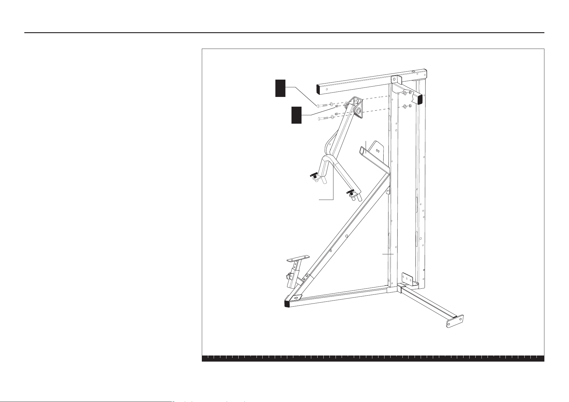
8. Attach Press Arm Assembly
CAUTION: This step requires two people. Do not
pinch yourself between the Press Arm and the
Prestretch Tube.
A. Attach the Press Arm Assembly to the Main
Upright using
two 4-inch bolts
four washers
two locknuts
Wrench tighten.
B. Check the alignment of the Press Arm
Assembly and Prestretch Tube. Wrench tighten.
C. Use the supplied allen wrench and tighten the set
screws.
Step 8. Attach Press Arm Assembly
Press Arm
Assembly
2 - 4" bolts
4 - washers
2 - locknuts
A
Prestretch
Tube
Main Upright
2 - set screws
C
S3.25 Assembly and Maintenance Guide
page 20
1 2 3 4 5 6
9. Attach Handlebars
A. Slide each Handlebar (one at a time) on the Pivot
Shaft.
B. To the end of each threaded Pivot Shaft, attach
one ½-inch washer
one ½-inch hat washer
one ½-inch locknut
Note: Tighten the locknut until the Handlebars
don't move. Then,
loosen
the locknut about
one-half turn until the arms pivot freely. A few
threads should show beneath the Pivot Shafts
if you've tightened it properly.
C. Secure the Plastic Caps over the locknuts.
A rubber mallet may be a useful tool to lightly tap
the caps into place.
Step 9. Attach Handlebars
Press Arm
Assembly
1 - plastic cap
Handlebars
Pivot Shaft
1 - ½" washer
1 - ½" hat washer
1 - ½" locknut
A
A
B
C
S3.25 Assembly and Maintenance Guide
page 21
1 2 3 4 5 6
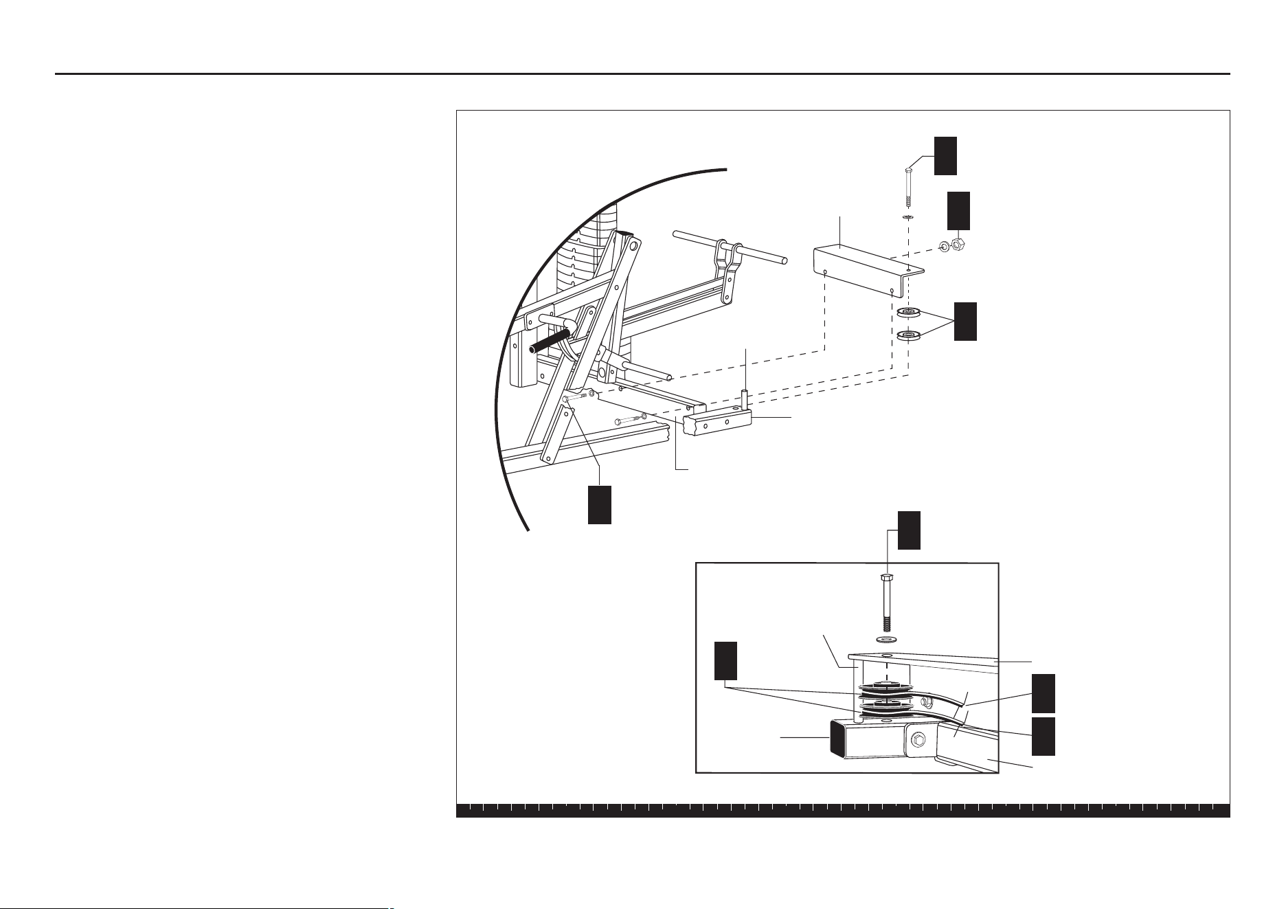
10. Assemble Chest Press Seat
A. Place the Backpad and Headrest on the floor. Place
the Long Support Tube and Short Support Tube on
the Backpad. Attach at the top using
two 1¼-inch bolts
two washers
B. Attach at the bottom using
three 3-inch bolts
three washers
C. Attach the Backpad and Headrest assembly to the
Chest Press Upright using
one ½-inch x 5¼-inch bolt
two washers
one locknut
Finger tighten.
Note: The Stop Pad on the seat assembly should
be between the Pop Pin and the Support Stop on
the Chest Press Upright.
D. Wrench tighten, still allowing movement.
CAUTION: If you move the Handlebars out of
the way for this step, be careful that they don’t
hit you.
E. Attach the Seat Pad to the Seat Stem using
two 1¼-inch bolts
two washers
Wrench tighten.
Note: If you have purchased the Leg Press Option,
open the S3.25 Leg Press Option box now and begin
with Step 2.
Step 10. Assemble Chest Press Seat
1
2
3
4
1
2
3
4
Long Support
Tube
Seat Pad
Backpad
1 - ½" x 5¼" bolt
2 - washers
1 - locknut
C
Seat Stem
Short
Support
Tube
2 - 1¼" bolts
2 - washers
E
Long Support Tube
Short
Support
Tube
3 - 3" bolts
3 - washers
B
2 - 1¼" bolts
2 - washers
A
Short Support
Tube
Long
Support
Tube
Backpad
Stop Pad
Pop Pin
Chest Press
Upright
Headrest
Headrest
The Backpad and Headrest are not
shown in this illustration.
S3.25 Assembly and Maintenance Guide
page 22
1 2 3 4 5 6
Open Box 4
Use tie cutters to open the box.
The diagram shows how the S3.25 will look after you
complete this section.
Note: Set aside the 2¾-inch bolt that is wrapped with
blue tape. It has special threads than can only be used
in step 16E.
Open Box 4
S3.25 Assembly and Maintenance Guide
page 23
1 2 3 4 5 6
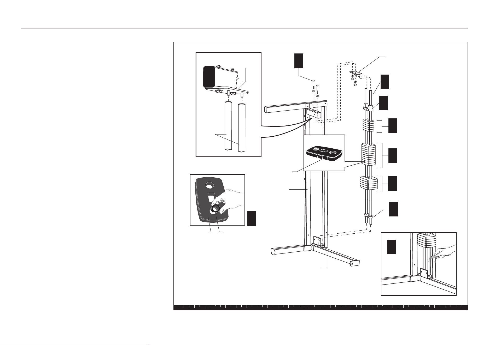
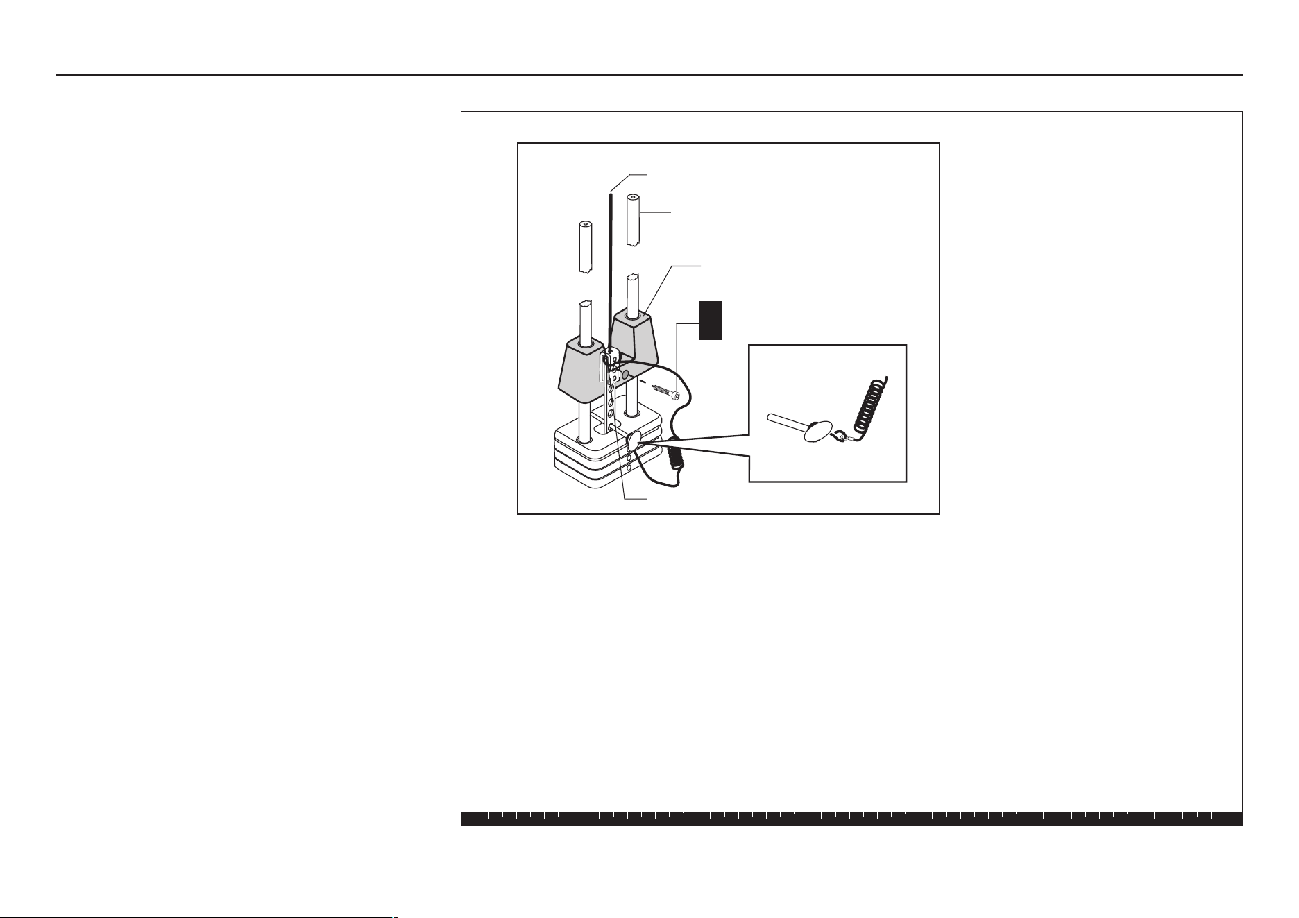
11. Assemble Weight Stack
Important: Position your unit in its permanent location
before assembling the Weight Stack.
A. Place a Weight Cushion on the base of two Guide
Rods (found in Box 1).
B. Insert the Guide Rods in the large holes on the
Main Upright Base. The Guide Rods will be
unstable until you complete step D. Slide the
Weight Stack Cushions onto the top of the Main
Upright Base.
C. Apply one tube of lubricant to each Guide Rod.
Avoid getting lubricant on your clothing or on other
parts of the machine.
D. Add the five 15-lb weights, the ten 10-lb weights,
and the five 5-lb weights. Note the tab location for
the weight stickers (you will attach the stickers
later). Hold your finger over the plastic bushing in
each weight to prevent the bushing from popping
out.
CAUTION: This step requires assistance. The
weights are heavy! Handle the weights
carefully so as not to drop them or injure
yourself. Pick up and place one weight at a time
on the Guide Rods. Have someone hold the
Guide Rods in place while you slide the
weights on the stack.
E. Position the Top Cap Weight on the Guide Rods so
that the hole is inline with the Weight Stack holes.
F. Insert the retainer pins of the Guide Rod Bracket in
the Guide Rods. Attach the Bracket to the Main
Upright using
two 4-inch bolts
four washers
two locknuts
G. Wrench tighten the Weight Stack bolts.
Step 11. Assemble Weight Stack
F
2 - 4" bolts
4 - washers
2 - locknuts
Guide Rod Bracket
D
Top Cap
Weight
5 - 5-lb Weights
10 - 10-lb Weights
5 - 15-lb Weights
Weight Cushions
D
D
A
Guide Rods
B
E
Main Upright Base
Main Upright
Guide Rod
Bracket
Guide
Rods
Tab for stickers
Plastic
bushing
Weight
D
C
S3.25 Assembly and Maintenance Guide
page 24
1 2 3 4 5 6
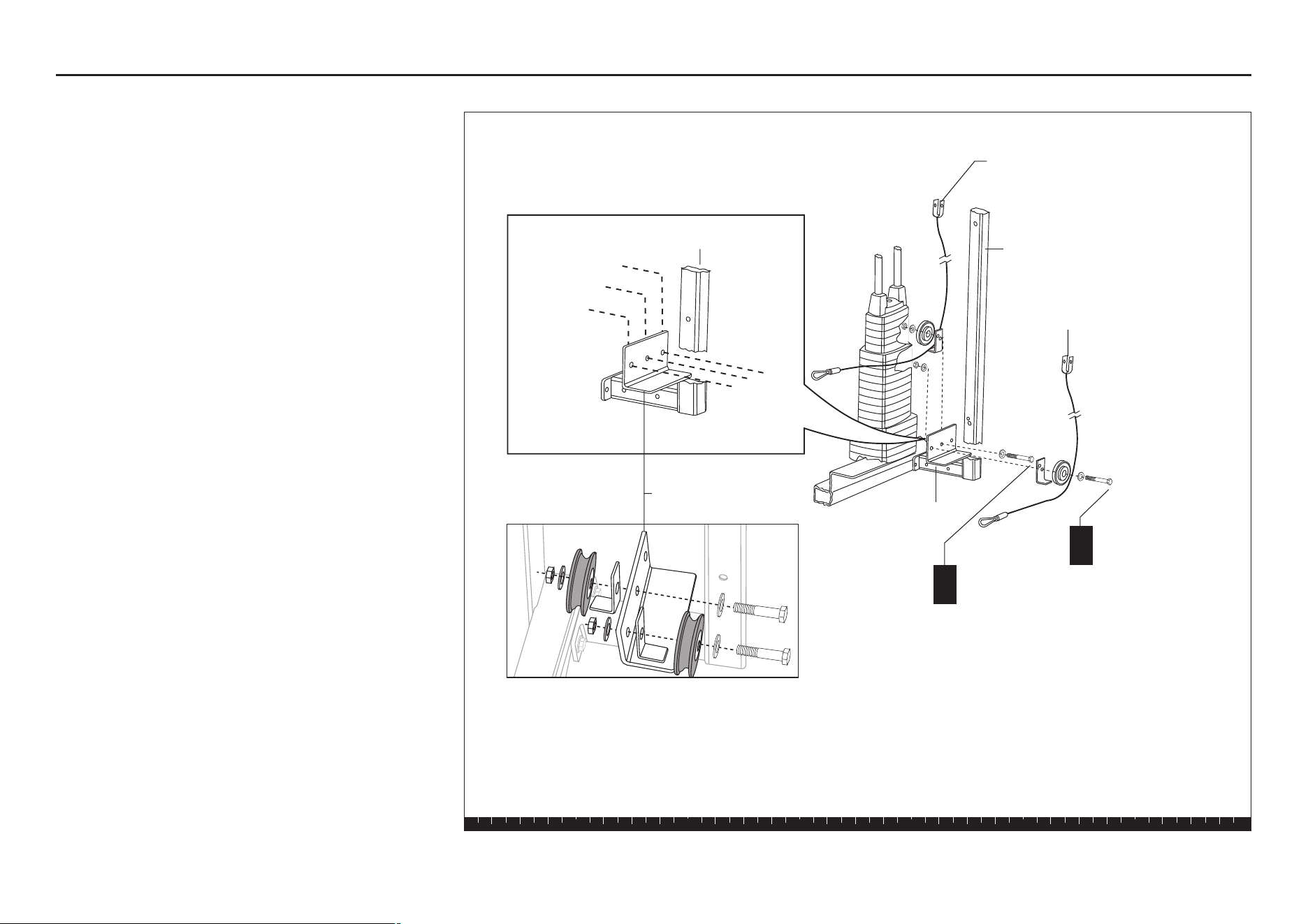
12. Feed Upper Cable
A. Attach a 4½-inch pulley to the top of the Main
Upright using
one 4¼-inch bolt
two washers
one barrel spacer
one locknut
B. Attach a 4½-inch pulley to the Angle Bracket at the
top of the Main Upright using
one 2½-inch bolt
two washers
one barrel spacer
one locknut
C. Feed the U end of Cable 44370-103 through the
pulley window in the Top Beam. Wrap the Cable over
a 4½-inch pulley and attach the pulley to the Top
Beam using
one 2¾-inch bolt
two step spacers
one locknut
D. Create a retainer pin in the remaining hole of the
Top Beam using
one 2¾-inch bolt
two washers
one locknut
E. Run the cable above the Top Beam and down
through the next pulley window and around a
4½-inch pulley. Attach the pulley to the Top Beam
using
one 3½-inch bolt
two step spacers
one locknut
one washer
one barrel spacer
one surgical tube
Wrench tighten.
F. Wrap the Cable around the pulleys as indicated
in the diagram and through the hole in the Guide
Rod Bracket.
Step 12. Feed Upper Cable
1 - 4½" pulley
1 - 2¾" bolt
2 - step spacers
1 - locknut
C
Pulley Window
Pulley Window
Top Beam
1 - 2¾" bolt
2 - washers
1 - locknut
D
E
1 - 4½" pulley
1 - 3½" bolt
2 - step spacers
1 - locknut
1 - washer
1 - barrel spacer
1 - surgical tube
Main Upright
Guide Rod Bracket
B
1 - 4½" pulley
1 - 2½" bolt
2 - washers
1 - barrel spacer
1 - locknut
Angle Bracket
Main Upright
A
1 - 4½" pulley
1 - 4¼" bolt
2 - washers
1 - barrel spacer
1 - locknut
F
Cable 44370-103
S3.25 Assembly and Maintenance Guide
page 25
1 2 3 4 5 6
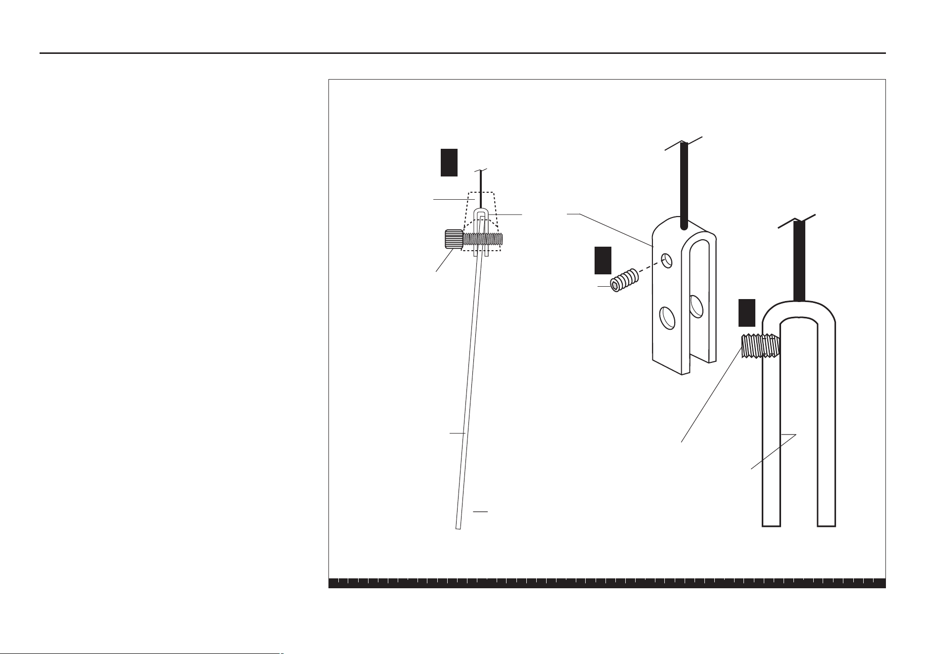
G. Insert the Selector Stem in the Weight Stack with
the threaded hole at the top. Hold the Selector
Stem with several holes above the Cap Plate.
Insert the Weight Pin to suspend the Selector
Stem. Place the loop end of the Weight Pin
Lanyard into the U end of the Cable. Align the U
end of the Cable, the top of the Selector Stem, and
the Cap Plate. Attach using
one 1½-inch socket cap bolt
H. Wrench tighten. Remove the Weight Pin and lower
the cap plate.
Step 12. Feed Upper Cable, Continued
G
1 - 1½" socket cap bolt
Guide Rods
Cap Plate
Weight Pin
Selector Stem
Cable 44370-103
S3.25 Assembly and Maintenance Guide
page 26
1 2 3 4 5 6
13. Attach Lat Bar Holders
A. Attach the Lat Bar Holders to the Top Beam using
two 3¼-inch bolts
four washers
two locknuts
B. Wrench tighten.
Step 13. Attach Lat Bar Holders
2 - 3¼" bolts
4 - washers
2 - locknuts
A
Top Beam
S3.25 Assembly and Maintenance Guide
page 27
1 2 3 4 5 6
14. Feed Cable From Cable Tree
A. Feed the Spring Clip end of Cable 44371-103 under
a 4½-inch pulley, through the lower pulley window of
the Main Upright, and through the upper pulley
window of the Main Upright. Attach the pulley to the
lower pulley window using
one 2¾-inch bolt
two step spacers
one locknut
B. Wrap the cable over a 4½-inch pulley and attach it
to the upper pulley window using
one 2¾-inch bolt
two step spacers
one locknut
C. Feed the Cable over one 4½-inch pulley and attach
it to the upper hole in the Press Arm Flats using
one 2-inch bolt
two washers
one locknut
Finger tighten.
D. Ensure the Cable wraps around the pulley and
then feed the Cable back through the Press Arm
Flats. Wrap the Cable over and around one 4½-
inch pulley and attach it to the Prestretch Tube
using
one 2-inch bolt
two washers
one cam washer
one locknut
Finger tighten.
Step 14. Feed Cable From Cable Tree
1 - 4½" pulley
1 - 2¾" bolt
2 - step spacers
1 - locknut
Main Upright
Press Arm
Lower Pulley
Window
A
1 - 4½" pulley
1 - 2¾" bolt
2 - step spacers
1 - locknut
B
Upper Pulley
Window
C
1 - 4½" pulley
1 - 2" bolt
2 - washers
1 - locknut
D
1 - 4½" pulley
1 - 2" bolt
2 - washers
1 - cam washer
1 - locknut
Cable Tree
Cable 44371-103
Prestretch
Tube
Spring Clip
S3.25 Assembly and Maintenance Guide
page 28
1 2 3 4 5 6
E. In the middle hole on the Press Arm Flats, make a
retainer pin using
one 2-inch bolt
two washers
one barrel spacer
one locknut
Finger tighten.
F. Wrap the Cable over one 3½-inch pulley and attach
it to the bottom hole on the Press Arm Flats using
one 2-inch bolt
two washers
one locknut
G. Wrench tighten. Do not overtighten.
H. Attach two large floating Pulley Plates (found in
Box 2) to one 4½-inch pulley using
one 2-inch bolt
two washers
one locknut
Finger tighten.
I. Place the pulley on the cable loop from Cable
44370-103.
J. Loop center Cable 44371-103 from the Cable Tree
around a 4½-inch pulley and attach it to the
remaining holes in the floating Pulley Plates using
one 2-inch bolt
two washers
one locknut
K. Wrench tighten.
Step 14. Feed Cable From Cable Tree, Continued
E
1 - 2" bolt
2 - washers
1 - barrel spacer
1 - locknut
F
1 - 3½" pulley
1 - 2" bolt
2 - washers
1 - locknut
H
1 - 4½" pulley
1 - 2" bolt
2 - washers
1 - locknut
J
1 - 4½" pulley
1 - 2" bolt
2 - washers
1 - locknut
J
44370-103
44371-103
I
Barrel
Spacer
Press Arm
Flats
S3.25 Assembly and Maintenance Guide
page 29
1 2 3 4 5 6
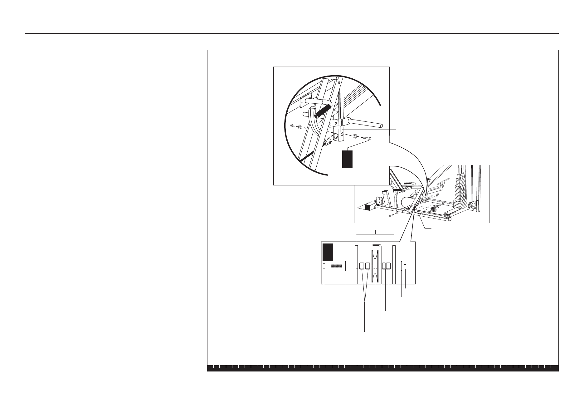
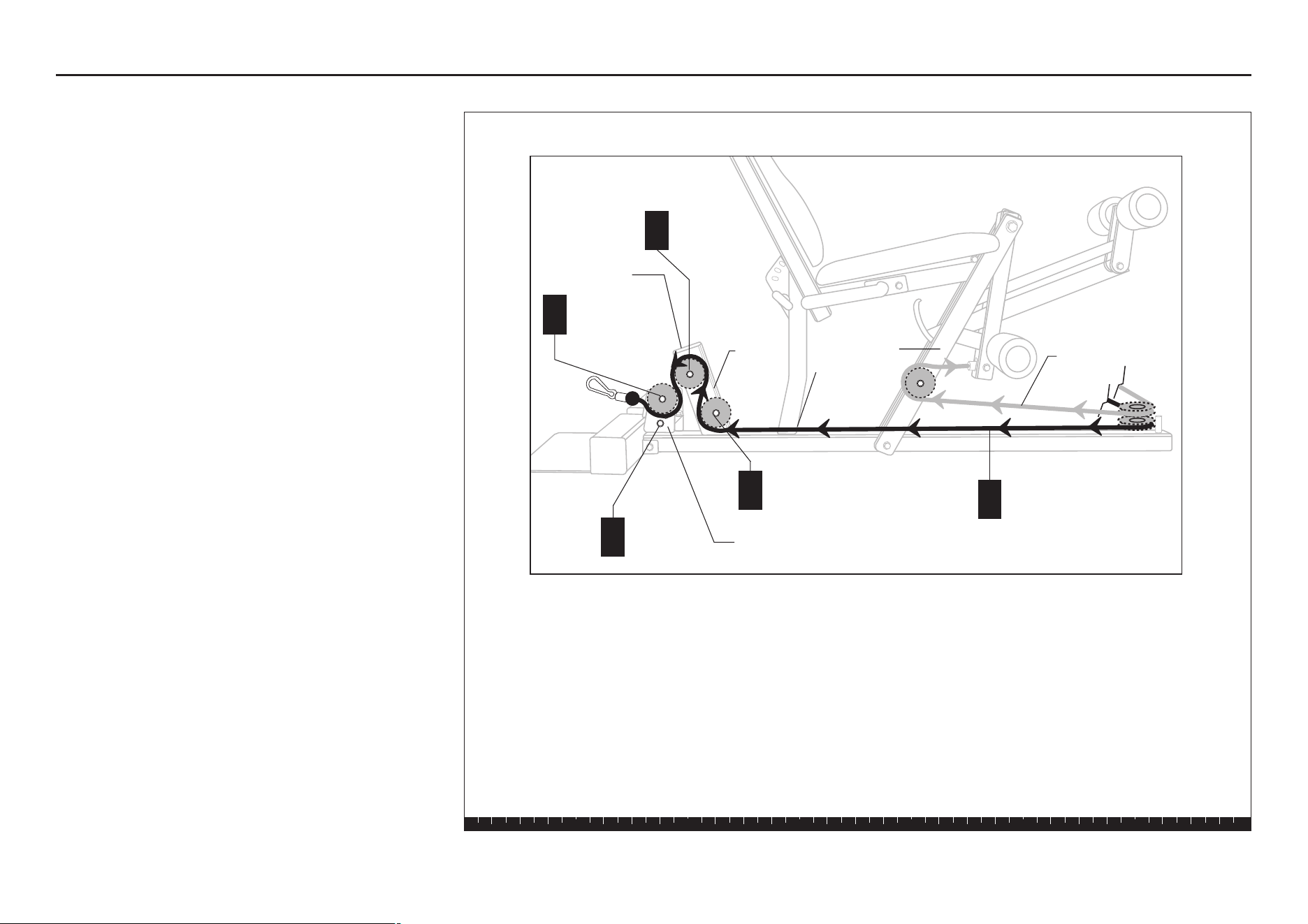
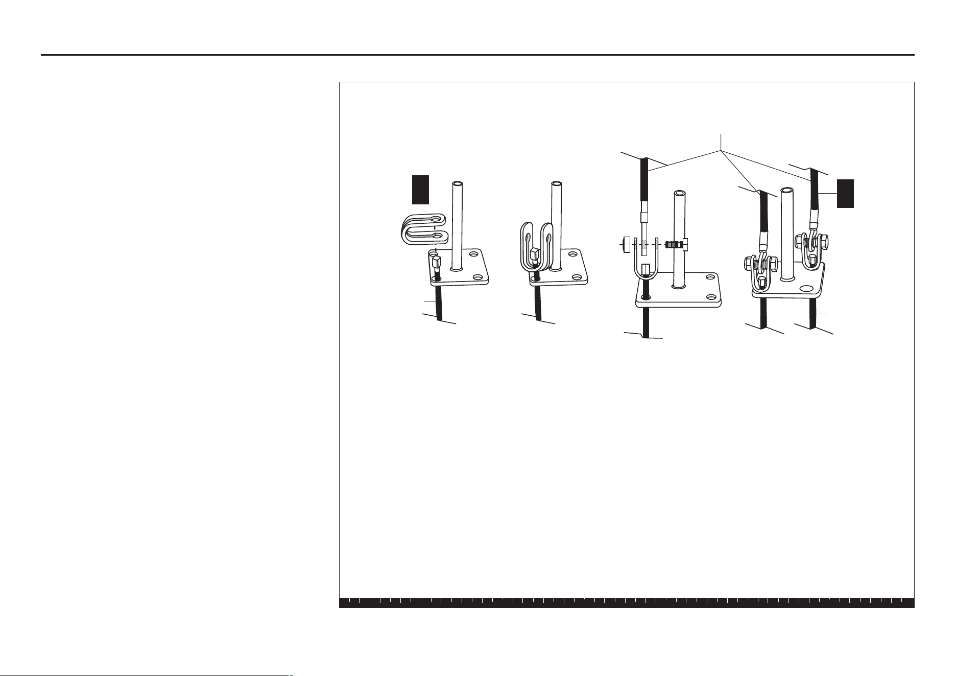
15. Attach Leg Curl Cables to
Lower Pulley Bracket
A. Wrap Cable 44376-102 around a 3½-inch pulley so
that the U end of the Cable faces up toward the
Cable Tree. Attach it and a Cable Retainer to the
left hole of the Lower Pulley Bracket at the base of
the Rear Upright using
one 2-inch bolt
two washers
one locknut
B. Wrap Cable 44375-103 around a 3½-inch pulley so
that the U end of the Cable faces up toward the
Cable Tree. Attach it and a Cable Retainer to the
back side of the middle hole of the Lower Pulley
Bracket using
one 2-inch bolt
two washers
one locknut
C. Wrench tighten.
Step 15. Attach Leg Curl Cables to Lower Pulley Bracket
Rear Upright
Lower Pulley Bracket
1 - 3½" pulley
1 - cable retainer
1 - 2" bolts
2 - washers
1 - locknut
A
Cable 44375-103 goes to
the Cable Tree
Cable 44376-102 goes to
the Cable Tree
Rear Upright
Right Hole
Center Hole
Left Hole
Lower Pulley
Bracket
1 - 3½" pulley
1 - cable retainer
1 - 2" bolts
2 - washers
1 - locknut
B
S3.25 Assembly and Maintenance Guide
page 30
1 2 3 4 5 6
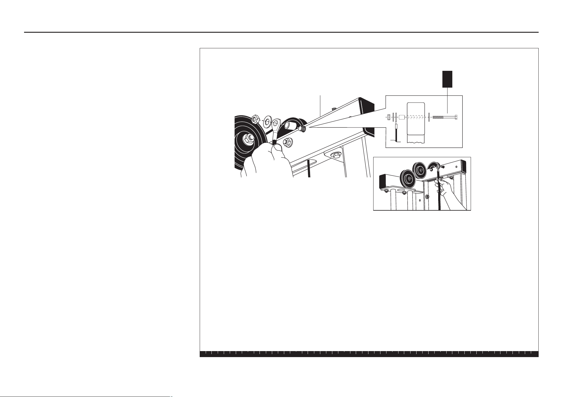
16. Attach Leg Curl Cables to
Seat Upright
A. Attach the Pulley Cover to the Main Upright Base
using
one 2¾-inch bolt (without blue tape)
two washers
one locknut
Finger tighten.
B. Place two 3½-inch pulleys on top of each other on
the Seat Extension.
C. Wrap Cable 44375-103 around the bottom pulley at
the end of the Seat Extension between the pulley
and the retainer pin.
D. Wrap Cable 44376-102 around the top pulley at the
end of the Seat Extension between the pulley and
the retainer pin.
Important: Be sure to use the 2¾-inch bolt
wrapped with the blue tape in step E.
E. Attach using
one 2¾-inch bolt (with blue tape)
one washer
F. Use the remaining hole in the Pulley Cover to
attach the Pulley Cover to the Main Upright Base
using
one 2¾-inch bolt
two washers
one locknut
Finger tighten.
G. Wrench tighten all bolts.
Step 16. Attach Leg Curl Cables to Seat Upright
Main Upright Base
Seat Extension
Pulley Cover
1 - 2¾" bolt (without blue tape)
2 - washers
1 - locknut
A
1 - 2¾" bolt (wrapped with blue tape)
1 - washer
E
1 - 2¾" bolt
2 - washers
1 - locknut
F
Retainer Pin
Retainer Pin
Seat
Extension
Pulley Cover
Cable 44376-102
Cable 44375-103
Main Upright Base
E
B
1 - 2¾" bolt (with blue tape)
1 - washer
2 - 3½" pulleys
D
C
B
2 - 3½" pulleys
S3.25 Assembly and Maintenance Guide
page 31
1 2 3 4 5 6
17. Feed Top Cable 44376-102
A. Attach Cable 44376-102 to the Rotating Arm using
one 2¾-inch bolt
two step spacers
one locknut
B. Wrap the Cable around a 4½-inch pulley and
attach it and a cable retainer to the Upright Flats
using
one 4½-inch bolt
two washers
one ³⁄₈-inch barrel spacer
three ½-inch barrel spacers
one locknut
Step 17. Feed Top Cable 44376-102
1 - 2¾" bolt
2 - step spacers
1 - locknut
A
1 - locknut
B
1 - 4½" bolt
1 - washer
1 ³⁄₈" barrel spacer
2 - ½" barrel spacers
1 - ½" barrel spacer
1 - washer
Upright Flats
Upright Flats
1 - 4½" pulley
1 - cable retainer
Rotating Arm
S3.25 Assembly and Maintenance Guide
page 32
1 2 3 4 5 6
18. Feed Bottom Cable
44375-103
A. Feed Cable 44375-103 through the Upright Flats,
through the Seat Upright Window, and into the
Pulley Window at the end of the Seat Upright.
B. Review the diagram and feed the Cable around one
3½-inch pulley. Attach the pulley using
one 2¾-inch bolt
two step spacers
one locknut
C. Wrap the Cable over a 3½-inch pulley and attach
it using
one 2¾-inch bolt
two step spacers
one locknut
Finger tighten.
D. Insert a 2-inch bolt as a retainer pin through the
base of the End Pulley Bracket. Attach it using
two washers
one locknut
E. Feed the Cable between the retainer pin and hole
in the End Pulley Bracket. Attach the 3½-inch
pulley to the End Bracket using
one 2-inch bolt
two washers
one locknut
Finger tighten.
Step 18. Feed Bottom Cable 44375-103
A
Cable 44375-103
C
E
B
1 - 3½" pulley
1 - 2¾" bolt
2 - step spacers
1 - locknut
1 - 3½" pulley
1 - 2" bolt
2 - washers
1 - locknut
1 - 3½" pulley
1 - 2¾" bolt
2 - step spacers
1 - locknut
Cable 44376-102
Pulley Bracket
Seat Upright
Window
D
1 - 2" bolt
2 - washers
1 - locknut
Upright Flats
Pulley
Window
End Pulley Bracket
S3.25 Assembly and Maintenance Guide
page 33
1 2 3 4 5 6
19. Attach Surgical Tubing to
Top Beam
A. Attach the other end of the surgical tubing to the
Top Beam using
one 3¼-inch bolt
two washers
one ½-inch barrel spacer
one locknut
Wrench tighten.
CAUTION: Surgical tubing may cause injury if
allowed to snap back as you pull the rubber tubing
tightly.
Step 19. Attach Surgical Tubing to Top Beam
Top Beam
A
1 - 3¼" bolt
2 - washers
1 - ½" barrel spacer
1 - locknut
S3.25 Assembly and Maintenance Guide
page 34
1 2 3 4 5 6
20. Attach Leg Curl Cables to
Cable Tree
A. Remove the U end of Cable 44376-102. Insert the
Cable in one of the corner holes of the Cable Tree.
Reattach the U end of the Cable with surgical tubing.
B. Remove the U end of Cable 44375-103. Insert the
Cable in the opposite corner of the Cable Tree.
Reattach the U end of the Cable with surgical tubing.
Note: If you are assembling the Leg Press Option
simultaneously, go to Step 5 in the
S3.25 Leg Press
Option Assembly Instructions
now.
Step 20. Attach Leg Curl Cables to Cable Tree
Surgical tubing
A
B
Cable 44376-102
Cable 44375-103
S3.25 Assembly and Maintenance Guide
page 35
1 2 3 4 5 6
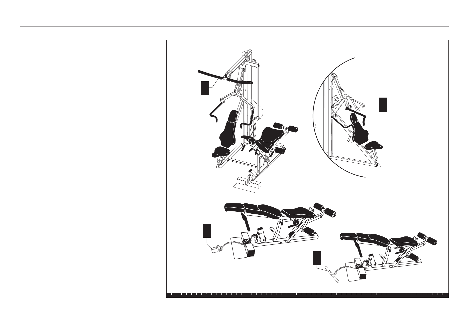
21. Attach Accessories
A. Attach the Lat Bar to the Spring Clip at the end of
the Top Beam.
B. Attach the Ab Crunch Strap to the Spring Clip on
the Press Arm.
C. Attach the Ankle Strap to the Spring Clip on the
Leg Station.
D. Attach the 18-inch Straight Bar to the Spring Clip on
the Leg Station to work out a different muscle
group.
Step 21. Attach Accessories
A
Lat Bar
B
Ab Crunch Strap
C
Ankle Strap
D
18-inch
Straight Bar
S3.25 Assembly and Maintenance Guide
page 36
1 2 3 4 5 6
22. Attach Shrouds
Important: Before attaching the Shrouds, make any
necessary adjustments. Refer to Chapter 4,
"Adjustments and Maintenance" on page 36 for
instructions.
A. Place one Large Shroud on each side of the Main
Upright and Rear Upright and attach using
six 2¾-inch bolts
twelve washers
six locknuts
B. Place the Small Shroud around the Weight Stack
and attach it to the Large Shroud using
two ¾-inch bolts
two washers
C. Attach the Small Shroud to the Angle Bracket in the
Main Upright Base using
one ¾-inch bolt
one washer
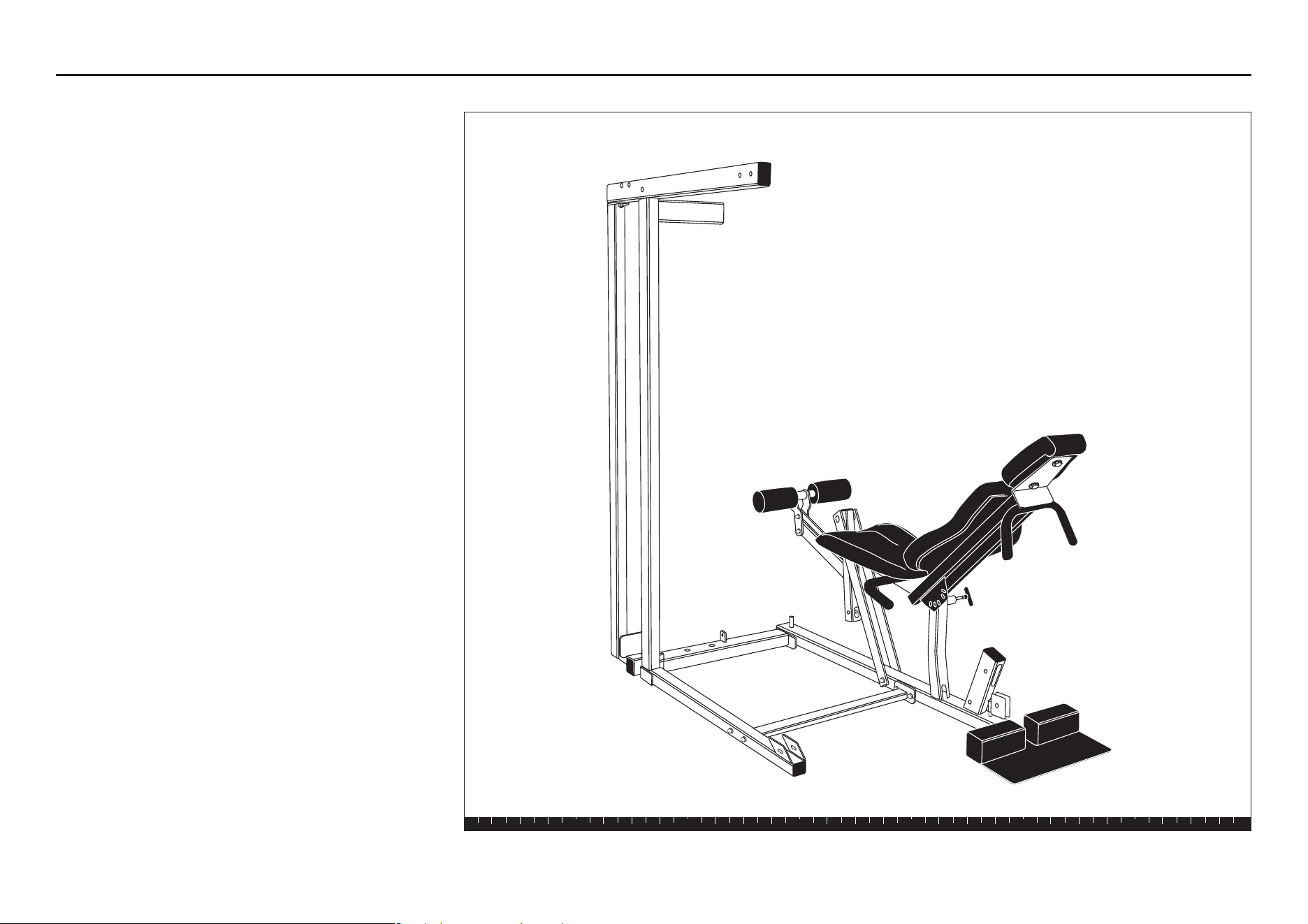
This completes the assembly of your Precor S3.25.
Step 22. Attach Shrouds
Large Shroud
Small
Shroud
B
2 - ¾" bolts
2 - washers
C
1 - ¾" bolt
1 - washer
Small Shroud
Angle Bracket
Main Upright Base
Weight Stack
A
6 - 2¾" bolts
12 - washers
6 - locknuts
Large Shroud
Main Upright
Large Shroud
S3.25 Assembly and Maintenance Guide
page 37
1 2 3 4 5 6
4
Adjustments and
Maintenance
After the S3.25 is completely assembled, you must
check the Cables for proper tension. Obvious signs that
Cable problems exist include:
✔ The Cap Plate does not rest squarely on the top
weight of the Weight Stack.
✔ The Cable rubs the inside edges of the pulleys.
✔ Excess slack exists in the Cable.
CAUTION: Take the time to perform the following
steps. If the Cables do not have the proper tension,
you could void the Precor Limited Warranty.
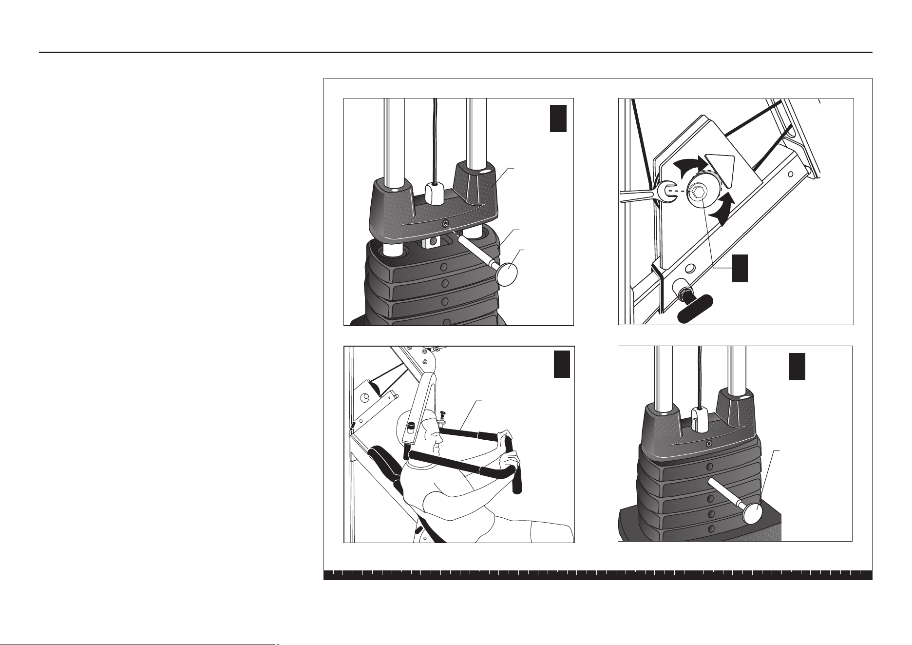
1. Cable Adjustments
A. Place the Weight Pin in the Top Cap to ensure the
least Cable resistance.
B. To remove slack from the Cable, pull up on the
Chest Press Handlebars and adjust the cam
washer.
C. Lower the Chest Press Handlebars.
D. Check the weights. Move the Weight Pin to each
weight plate and Selector Stem location.
Adjustments and Maintenance
C
Chest Press Arms
B
Cam Washer
Top Cap
Weight
Weight
Pin
A
Top Weight
D
Weight
Pin
S3.25 Assembly and Maintenance Guide
page 38
1 2 3 4 5 6
2. Selector Stem Adjustments
To prevent the Selector Stem from contacting the inside
of the Weight Stack when the machine is in use, you
need to check the vertical angle of the Selector Stem
(steps A and B). If the stem slides smoothly without
contacting the inside of the weight plates, assembly of
the unit is complete.
Caution: Performing the following tasks requires
two people.
A. Remove the Weight Pin from the Weight Stack.
B. Perform an exercise using each part of the S3.25.
When the base of the Selector Stem is clear of
the Weight Stack, observe the position of the
Selector Stem.
The following sections describe how to adjust the
Selector Stem when contact does occur.
The Selector Stem can be adjusted forward or
backward, depending on the area of contact.
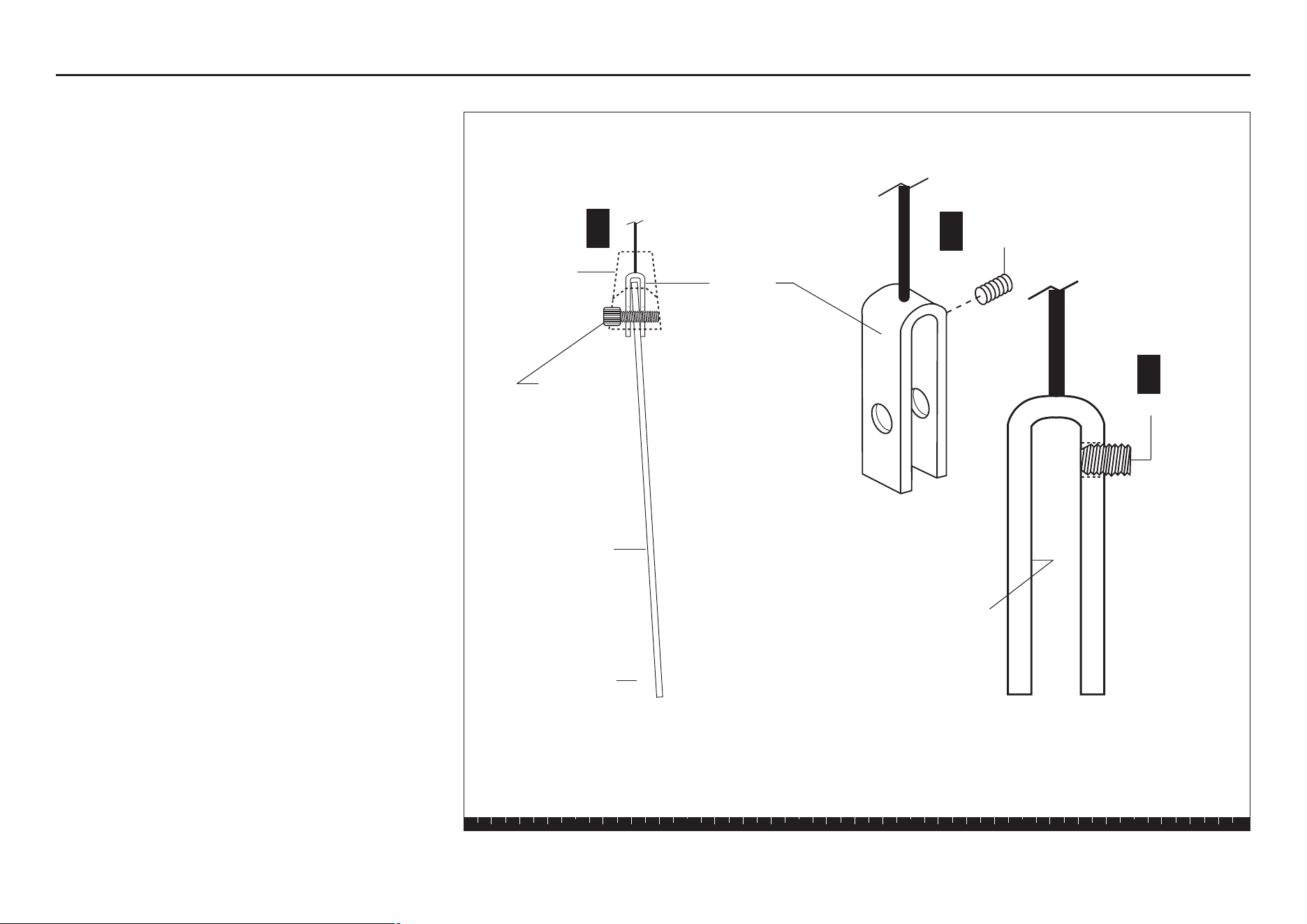
Forward Angle Adjustment
When the Selector Stem angles forward (toward the
seat) and contacts the inside of the Weight Stack
during use, adjust it by taking these steps:
Caution: This adjustment requires two people.
A. Completely disassemble the Cap Plate,
Selector Stem, and Cable Clamp.
B. Thread Allen head set screw into the hole closest
to the top of the U end of the cable and turn
clockwise until the end of the screw is flush with
the inside surface of the clamp.
C. Turn the set screw clockwise another one-half turn
(see diagram).
Step 2. Selector Stem Adjustments
Forward Angle
Selector Stem
Cap Plate
1 ½" Socket
Cap Bolt
U Bracket
Allen head
Set screw
Inside
surface
Set screw
▲
A
B
B
Forward Angle Adjustment
S3.25 Assembly and Maintenance Guide
page 39
1 2 3 4 5 6
D. Reassemble the Cap Plate, Selector Stem, and
Cable Clamp.
E. Test the movement of the Selector Stem inside the
Weight Stack.
F. If the Selector Stem continues to contact the
plates, repeat steps A through E until the Selector
Stem slides through the Weight Stack without
contacting the plates.
Backward Angle Adjustment
When the Selector Stem angles backward (away from
the seat) and contacts the inside of the Weight Stack
during use, adjust it by taking these steps:
Caution: This adjustment requires two people.
A. Completely disassemble the Cap Plate, Selector
Stem, and Cable Clamp.
B. Thread Allen head set screw into the hole closest
to the top of the U end of the Cable and turn
clockwise until the end of the screw is flush with
the inside surface of the clamp.
C. Turn the set screw clockwise another one-half turn
(see diagram).
D. Reassemble the Cap Plate, Selector Stem, and
Cable Clamp.
E. Test the movement of the Selector Stem inside the
Weight Stack.
F. If the Selector Stem continues to contact the
plates, repeat steps A through E until the Selector
Stem slides through the Weight Stack without
contacting the plates.
Step 2. Selector Stem Adjustments, Continued
Backward Angle
Selector Stem
▲
Cap Plate
1 ½" Socket
Cap Bolt
Allen head
set screw
Set screw
U Bracket
Inside
surface
B
B
A
Backward Angle Adjustment
S3.25 Assembly and Maintenance Guide
page 40
1 2 3 4 5 6
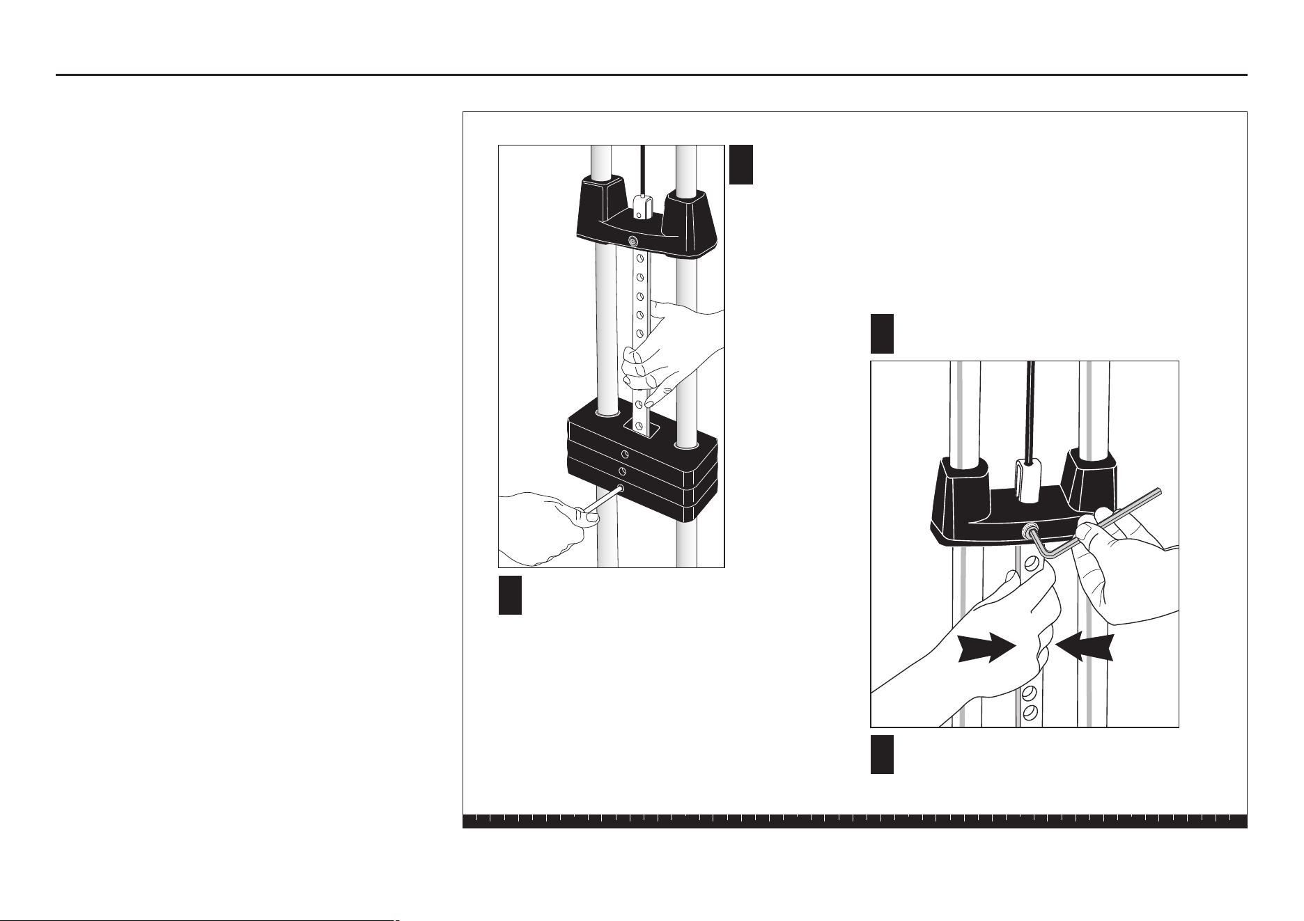
Side-to-Side Vertical Adjustment
If the Selector Stem contacts the inside of the Weight
Stack during use or the Weight Pin becomes difficult to
insert in the Weight Stack, the Selector Stem may be
out of alignment vertically side to side
.
Adjust the
Selector Stem by taking these steps:
Caution: Performing these steps requires two
people.
A. Pull the Selector Stem and Top Cap up to expose
at least five Selector Stem holes.
B. Insert the Weight Pin near the base of the Selector
Stem to hold it in place.
C. To center the Selector Stem, loosen the socket cap
bolt that attaches the Top Cap to the U bracket.
D. Once the Selector Stem is centered, retighten the
socket cap bolt securely.
E. Lower the Selector Stem into the Weight Stack.
Test the movement of the Selector Stem inside the
Weight Stack.
F. Make certain that the Weight Pin can be inserted
into every hole in the Weight Stack. If the Selector
Stem continues to contact the plates, repeat steps
A through E until the Selector Stem slides through
the Weight Stack without contacting the plates.
After completing the adjustments, fill out the warranty
card and mail it in.
3. Maintenance
Lubricate the Guide Rods every six months.
Thank you for choosing Precor!
Step 3. Maintenance
A
B
Pull the Selector Stem and
Top Cap Weight up to
expose at least 5 holes.
Hold the stem in place by inserting
the Weight Pin (through a weight)
near the base of the Selector Stem.
C
Loosen the socket cap bolt and align the
Selector Stem.
D
Once the Selector Stem is centered, retighten the
socket cap bolt securely.

page 41
RET.
To allow us to serve you better, please take a few moments to
complete and return your warranty registration.
YOU MAY ALSO REGISTER ONLINE AT
www.precor.com/warranty
If you have questions or need additional information, contact your
local dealer or call Precor Customer Support at 800-347-4404.
Thank You and Welcome to Precor
Precor Incorporated
20031 142nd Avenue NE
PO Box 7202
Woodinville, WA 98072-4002
PLACE
STAMP
HERE

page 42
TELL US ABOUT YOUR NEW PRECOR PRODUCT
Purchased
from:
The serial number is located on the shipping box and on the product.
Product
Serial
Number:
Please indicate the type of product purchased:
❑ Elliptical Fitness CrossTrainer (EFX
®
)
❑ Treadmill
❑ Strength Training System
TELL US ABOUT YOU
Date of
Purchase:
❑ Mr.
❑ Mrs.
❑ Ms.
First Name
Apt./Suite:
TELL US ABOUT YOUR PURCHASE
Please detach and mail in the warranty registration within ten days of purchase.
❑ StretchTrainer
TM
❑ Cycle
❑ Stair Climber
Middle Initial Last Name
Street Address
Zip CodeCity State
Gender: Marital status: Age: Annual household income: What are your fitness goals?
❑ Male ❑ Married ❑ Under 18 ❑ Under $50,000 ❑ Weight loss/management
❑ Female ❑ Divorced ❑ 18-24 ❑ $51,000-75,000 ❑ Muscle tone enhancement
❑ Widowed ❑ 25-34 ❑ $76,000-100,000 ❑ Cardiovascular improvement
❑ Never been married ❑ 35-44 ❑ $101,000-150,000 ❑ Overall health
❑ 45-54 ❑ $151,000+ ❑ Increase energy and flexibility
❑ 55-64 ❑ Stress reduction
❑ 65+ ❑ Rehabilitation
❑ Other
Purchase (check all that apply): How did you FIRST become aware of Precor
❑ First Precor product products (choose only one):
❑ Replaces a Precor product of the same type ❑ A gift
❑ Replaces same type of product – different brand ❑ Friend/relative
❑ Addition to equipment currently owned ❑ Physician
❑ Fitness club
❑ Internet
What factors MOST influenced your decision to ❑ News report or product review
purchase your Precor product (choose up to three): ❑ Magazine advertisement or article
❑ Precor reputation ❑ Print advertisement
❑ Prior use of Precor product(s) ❑ In-store display or demonstration
❑ Design/appearance ❑ Other
❑ Value for the price
❑ Special product features
❑ Rebate or sale price
❑ Quality/durability
❑ Warranty
❑ Physician recommendation
Month
Day
Year
Your Email Address
Area Code
Telephone
Dealer Name
Effective 01 July 2004
P/N 45623-102

Effective 01 January 2003
P/N 36287-110
Precor Residential Equipment Limited Warranty
PLEASE READ THESE WARRANTY TERMS AND CONDITIONS CAREFULLY BEFORE USING
YOUR PRECOR INCORPORATED PRODUCT. BY USING THE EQUIPMENT, YOU ARE
CONSENTING TO BE BOUND BY THE FOLLOWING WARRANTY TERMS AND CONDITIONS.
Limited Warranty.
Precor Incorporated warrants all new Precor products to be free from defects in materials and
manufacture for the warranty period set forth below. The warranty period commences on the
invoice date of original purchase. This warranty applies only against defects discovered within
the warranty period and extends only to the original purchaser of the product. Parts repaired or
replaced under the terms of this warranty will be warranted for the remainder of the original
warranty period only. To make claim under warranty, the buyer must notify Precor or their
authorized Precor dealer within 30 days after the date of discovery of any nonconformity and
make the affected product available for inspection by Precor or its service representative.
Precor’s obligations under this warranty are limited and set forth below.
Warranty Periods and Coverage
All residential products and commercial products used in the home are warranted for the
following periods:
• Lifetime frame and welds
• 10 years parts and wear items
• 1 year labor
• Coverage for options and accessories defined below.
Options / Accessories
Many options or accessories have components that are connected internally or mounted inside the
electronic console. The following guidelines determine the warranty for these components. If the
internal components are installed by the factory or by an authorized dealer as part of the original
sale and delivery, they have a warranty that is identical to the warranty of the equipment in which
they are connected or mounted. If the internal components are not installed by the factory or by an
authorized dealer as part of the original sale and delivery, they have a 90-day parts and labor
limited warranty. All components that are not internally connected have 90-day parts only limited
warranty. Satisfactory proof of purchase is required in all cases.
Conditions and Restrictions
This warranty is valid only in accordance with the conditions set forth below:
1. The warranty applies to the Precor product only while:
a. It remains in the possession of the original purchaser and proof of purchase is
demonstrated
b. It has not been subjected to accident, misuse, abuse, improper service, or non-Precor
modifications
c. Claims are made within the warranty period
2. This warranty does not cover damage or equipment failure caused by electrical wiring not in
compliance with electrical codes or Precor owner’s manual specifications, or failure to provide
reasonable and necessary maintenance as outlined in the owner’s manual.
3. Warranty of all Precor products applies to residential use only and is void when products are
used in a nonresidential environment or installed in a country other than where sold.
4. Except in Canada, Precor does not pay labor outside the United States.
5. Warranties outside the United States and Canada may vary. Please contact your local Dealer
for details.
This limited warranty shall not apply to:
1. Software version upgrades
2. Cosmetic items, including, but not limited to the following: grips, seats, and labels.
3. Repairs performed on Precor equipment missing a serial number or with a serial tag that has
been altered or defaced.
4. Service calls to correct installation of the equipment or instruct owners on how to use the
equipment.
5. Pickup, delivery, or freight charges involved with repairs.
6. Any labor costs incurred beyond the applicable labor warranty period.
Disclaimer and Release
The warranties provided herein are the exclusive warranties given by Precor and supersede any prior,
contrary or additional representations, whether oral or written. ANY IMPLIED WARRANTIES, INCLUDING THE
WARRANTY OF MERCHANTABILITY OR FITNESS FOR A PARTICULAR PURPOSE THAT APPLY TO ANY PARTS DESCRIBED ABOVE
ARE LIMITED IN DURATION TO THE PERIODS OF EXPRESS WARRANTIES GIVEN ABOVE FOR THOSE SAME PARTS. PRECOR
HEREBY DISCLAIMS AND EXCLUDES THOSE WARRANTIES THEREAFTER.
Some states do not allow limitation on how
long an implied warranty lasts, so the above limitation may not apply to you. PRECOR ALSO HEREBY DISCLAIMS
AND EXCLUDES ALL OTHER OBLIGATIONS OR LIABILITIES, EXPRESS OR IMPLIED, ARISING BY LAW OR OTHERWISE, WITH
RESPECT TO ANY NONCONFORMANCE OR DEFECT IN ANY PRODUCT, INCLUDING BUT NOT LIMITED TO: (A) ANY OBLIGATION,
LIABILITY, RIGHT, CLAIM OR REMEDY IN TORT, WHETHER OR NOT ARISING FROM THE NEGLIGENCE OF PRECOR OR ITS
SUPPLIERS (WHETHER ACTIVE, PASSIVE OR IMPUTED); AND (B) ANY OBLIGATION, LIABILITY, RIGHT, CLAIM, OR REMEDY FOR
LOSS OF OR DAMAGE TO ANY EQUIPMENT.
This disclaimer and release shall apply even if the express warranty set
forth above fails of its essential purpose.
Exclusive Remedies
For any product described above that fails to conform to its warranty, Precor will provide, at their option, one of
the following: (1) repair; (2) replacement; or (3) refund of the purchase price. Precor Limited Warranty service
may be obtained by contacting the authorized dealer from whom you purchased the item. Precor
compensates Servicers for warranty trips within their normal service area to repair equipment at the owner’s
location. You may be charged a trip charge outside the service area. THESE SHALL BE THE SOLE AND EXCLUSIVE
REMEDIES OF THE BUYER FOR ANY BREACH OF WARRANTY.
Exclusion of Consequential and Incidental Damages
PRECOR AND/OR ITS SUPPLIERS SHALL HAVE NO OBLIGATION OR LIABILITY, WHETHER ARISING IN CONTRACT
(INCLUDING WARRANTY), TORT (INCLUDING ACTIVE, PASSIVE, OR IMPUTED NEGLIGENCE AND STRICT LIABILITY), OR
OTHERWISE, FOR DAMAGE TO THE EQUIPMENT, PROPERTY DAMAGE, LOSS OF USE, REVENUE OR PROFIT, COST OF
CAPITAL, COST OF SUBSTITUTE EQUIPMENT, ADDITIONAL COST INCURRED BY BUYER (BY WAY OF CORRECTION OR
OTHERWISE) OR ANY OTHER INCIDENTAL, SPECIAL, INDIRECT, OR CONSEQUENTIAL DAMAGES, WHETHER
RESULTING FROM NONDELIVERY OR FROM THE USE, MISUSE OR INABILITY TO USE THE PRODUCT.
This exclusion
applies even if the above warranty fails of its essential purpose and regardless of whether such damages
are sought for breach of warranty, breach of contract, negligence, or strict liability in tort or under any other
legal theory. Some states do not allow the exclusion or limitation of incidental or consequential damages,
so the above limitation might not apply.
This warranty gives you specific legal rights, and you may also have other rights, which vary state
to state.
Complete this portion and keep for your records.
Purchased From: ____________________________ Example: Dealer or store name.
Phone Number: _____________________________ Example: Dealer or store telephone number.
Product/model: _____________________________ Example: M9.31
Serial number: ______________________________ The serial number is found on the shipping container

S3.25 Specifications
Length: 66 inches (168 cm)
Height: 82 inches (208 cm)
Width: 48 inches (122 cm) Leg press option adds 15 inches (38 cm)
Shipping weight: 339 lb (154 kg)
S3.25 Literature Kit # 47941-104
Owner's Manual # 47996-104
Warranty Registration # 45623-102
Warranty Card # 36287-110
Effective date: 01 May, 2006
Precor and Pacific Fitness are registered trademarks of Precor Incorporated.
Specifications subject to change without notice.
Copyright 2006 Precor Incorporated.
Precor web site: www.precor.com
Precor Incorporated
20031 142nd Avenue NE
P.O. Box 7202
Woodinville, WA USA 98072-4002
NOTICE:
Precor is widely recognized for its innovative, award winning designs of exercise equipment. Precor aggressively seeks U.S. and foreign patents for
both the mechanical construction and the visual aspects of its product design. Any party contemplating the use of Precor’s product designs is hereby
forewarned that Precor considers the unauthorized appropriation of its proprietary rights to be a very serious matter. Precor will vigorously pursue all
unauthorized appropriation of its proprietary rights.