v3.0
User Manual
DJI TERRA
2021.05

©
2021 DJI All Rights Reserved.
1
Content
Disclaimer
2
Warning
2
Introduction
2
Download and Launch
3
Connect the Remote Controller and Aircraft
4
Mission Type
4
Flight Route Missions 4
Reconstruction Missions 5
Interface Introduction
7
Main Screen 7
Flight Route Mission Editing View 9
Flight Route Missions
11
Create a Mission 11
Perform Mission 13
Parameter Setting Introduction 15
Reconstruction Missions
30
Importing Image POS Data 30
Using the PPK Result Files 31
2D Map Reconstruction 32
2D Multispectral Map Reconstruction 35
Agricultural Application 36
3D Model Reconstruction 40
ROI Reconstruction 43
Output Coordinate System Settings 44
GCP Management 45
LiDAR Point Cloud Processing 48
More Functions
50
Purchase Licenses 50
Activate Online Licenses and Bind Devices 51
Cluster Reconstruction 51
View and Export Logs 55
Software Shortcuts 55

2
©
2021 DJI All Rights Reserved.
Disclaimer
Read this disclaimer and the terms in DJI TERRA
TM
(hereinafter referred to as “product”) carefully
before using this product. By using this product, you hereby agree to this disclaimer and the Terms
of Use and signify that you have read it fully. Please install and use this product in strict accordance
with the User Manual. SZ DJI TECHNOLOGY CO., LTD. and its afliated companies assume no
liability for damage(s) or injuries incurred directly or indirectly from using this product improperly.
DJI
TM
is a trademark of SZ DJI TECHNOLOGY CO., LTD. (abbreviated as “DJI”) and its afliated
companies. Names of products, brands, etc., appearing in this manual are trademarks or registered
trademarks of their respective owner companies. This product and manual are copyrighted by DJI
with all rights reserved. No part of this product or manual shall be reproduced in any form without
the prior written consent of or authorization from DJI.
This disclaimer is produced in various languages. In the event of variance among different versions, the
Chinese version shall prevail when the product in question is purchased in China, and the English version
shall prevail when the product in question is purchased in any other region.
Warning
1. Ensure your ight area is safe before each ight.
2. Be sure to maintain a visual line of sight (VLOS) to your aircraft at all times.
3. The aircraft will continue its mission, meaning Failsafe RTH will not be triggered, if the remote
controller signal is lost during the mission.
4. When the GNSS signal is strong and the RTH button is pressed and held during a mission, the
aircraft will stop the mission immediately and begin RTH. Users can resume the mission if required.
5. When there is only sufcient battery power for RTH during a mission, the remote controller will
alert for a few moments, the aircraft will pause the mission, and begin RTH. After replacing the
battery, the mission can resume from the paused point
6. When using an aircraft with obstacle avoidance function, check that the Sensing System is
operational in the current surroundings. If it is not, disable it in DJI Terra (go to
> ), or ight
may be adversely affected.
7. All of the altitude values in DJI Terra are relative to the altitude of the takeoff point. In the same
mission, the altitude above sea level for the same point during the mission will vary if taking off at
different altitudes.
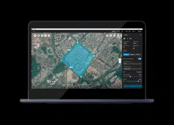
Introduction
DJI Terra is a PC software designed to improve mission performance efficiency for industrial
applications including — but not limited to — agricultural plant protection, search and rescue,
and reghting. It can control a DJI aircraft* to y along a planned 2D or 3D route and provides
functions such as 2D map reconstruction, 3D model reconstruction, eld planning, and more.
* Support for DJI devices will be added as testing and development continues. Visit the DJI Terra product
page on dji.com for a complete list. https://www.dji.com/dji-terra
DJI Terra has four versions: Agriculture, Pro, Electricity, and Cluster. To purchase DJI Terra, visit
the DJI Online Store or the ofcial DJI website. After purchasing, activate licenses and bind devices
using DJI Terra. For more information, refer to “More Functions” on p. 50.
Agriculture version includes functions such as real-time 2D mapping, 2D map reconstruction (for
eld and fruit tree scenes), 2D multispectral reconstruction, agriculture applications, and LiDAR
point cloud processing.
©
2021 DJI All Rights Reserved.
3
DJI TERRA
User Manual
Pro version includes all the functions from Agriculture version with additional functions such as
importing KML files, importing image POS data, 2D map reconstruction (for urban scenes), ROI
reconstruction, output coordinate system settings, multi-GPU reconstruction, 3D model reconstruction,
3D Mission Planning, GCP management, and LiDAR point cloud accuracy optimization.
Electricity version includes all the functions from Pro version with additional functions such as 3D
model reconstruction (for power lines scenes) and detailed inspection.
Cluster version includes all the functions mentioned above and enables multiple devices in the
same local network to be used to perform cluster reconstruction.
NOTE: The Agriculture version is only available in China.
Download and Launch
DJI Terra is supported on Windows 7 (64-bit) or later.
Your computer should meet certain hardware requirements for optimal use of some of the advanced
functions such as reconstruction.
Hardware Real-time 2D Mapping
2D Map Reconstruction / 3D Model
Reconstruction / Real-time 3D Mapping
LiDAR Point Cloud
Processing
CPU i5 or later
GPU
NVIDIA graphics card
is recommended
GeForce GTX TITAN X, GeForce RTX 2080 Ti
GeForce GTX 1080 Ti, GeForce GTX 1080
GeForce GTX 1070 Ti, GeForce GTX 1070
GeForce GTX 1060, GeForce GTX 1050 Ti
GeForce GTX 970, GeForce GTX 960
Other NVIDIA graphics cards with a compute capability of no less than 3.0
VRAM No less than 4GB No less than 4GB
RAM No less than 8GB No less than 16GB No less than 32GB
HDD 50GB Free (basic requirement) or SSD+50GB Free (better)
NOTE:
The requirements for 2D map reconstruction / 3D model reconstruction / real-time 3D mapping
are equally applicable to real-time 2D mapping. There are no mandatory requirements on the
graphics card for real-time 2D mapping. However, using a low-performance computer for real-time
2D mapping may result in delayed performance. If using an NVIDIA graphics card, the processing
speed will be faster.
It is recommended to use the graphics cards listed above. If using other models, please contact
DJI Support before use.
Make sure that the graphics card driver is up-to-date regardless of the models.
Refer to Preparation Before Using DJI Terra on the ofcial DJI website for more information on
hardware and other conguration requirements when using the Cluster version.
1. Visit the DJI Terra product page on dji.com using your computer to download and install the software.
2. Launch DJI Terra and log in with your DJI account. If an ofine license was purchased, ofine
login is required. Refer to Preparation Before Using DJI Terra for more information.
DJI devices must be activated before using DJI Terra.
4
©
2021 DJI All Rights Reserved.
Set a waypoint ight path, then dene waypoint actions for each waypoint.
Connect the Remote Controller and Aircraft
Using Phantom 4 RTK / Phantom 4 Pro V2.0 / Phantom 4 Pro+ V2.0
Connect the remote controller to the computer using a USB-C cable (for the Phantom 4 RTK) or
Micro USB cable (for the Phantom 4 Pro V2.0 / Phantom 4 Pro+ V2.0), then power on the remote
controller and aircraft. The location and status information of the aircraft will display on DJI Terra.
When using the Phantom 4 Pro V2.0, make sure to connect the remote controller to the
computer rst and then power it on. Otherwise, DJI Terra cannot recognize the device.
Currently, the Phantom 4 RTK (SDK) remote controller (which refers to the Phantom 4 RTK
remote controller without a display device) is not supported by DJI Terra.
Using Other Devices
1. Switch remote controller communication mode to PC mode.
a. Power on the remote controller. Make sure the flight mode is P-mode. Then, connect the
remote controller (Micro USB port) to PC (USB port) via a Micro USB cable.
b. Launch DJI Terra, enter
> , choose “Switch to PC Mode.” The status LED of the remote
controller will blink red (blink green if the aircraft is connected), indicating that the remote
controller is in PC mode. Restart the remote controller to enable PC mode.
2. Remove the Micro USB cable. Connect the remote controller (USB port) to PC (USB port) via an
A male to A male USB cable, then power on the aircraft. The location and status information of
the aircraft will display in DJI Terra.
If you want to use DJI GO 4 or other apps on a mobile device connected to the USB port on
the remote controller, be sure to switch the remote controller communication mode to App
mode in DJI Terra. The switching procedure is similar to the one above. The only difference
is choosing “App Mode.”
Mission Type
Flight Route Missions
Waypoints
DJI Terra automatically generates efcient ight paths after user has set their required
ight area and camera parameters. The aircraft will then follow this route throughout
its mission. Real-time 2D mapping or real-time 3D mapping (of low accuracy) during
a mission can be enabled. After the mission is complete, users can also import the
original images into DJI Terra for 2D map reconstruction or 3D model reconstruction (of
high accuracy).
Mapping
©
2021 DJI All Rights Reserved.
5
This function automatically generates five flight paths after users have set their
required ight area and parameters. These include a single ight path with a gimbal
pitch angle of -90°, indicating a downward facing direction. Subsequently, this is
followed by four flight paths with a customizable gimbal pitch of more than -90°
to capture photos from multiple angles such as forward, backward, leftward, and
rightward. After the mission is complete, users can import the original images onto
DJI Terra for 3D model reconstruction of different resolutions.
Oblique
Corridor
DJI Terra automatically generates corridor ight area and several independent
flight paths after the user has set the corridor points, expansion distance, and
ight band cutting distance. After the mission is complete, users can import the
original images into DJI Terra for 2D map or 3D model reconstruction.
Use the original photos captured by the camera to obtain a high-precision 2D
map. After a map has been produced, users have the option to add annotations
and perform a variety of measurements.
Use the original photos captured by the multispectral cameras to obtain a high-
precision 2D multispectral map. After a map has been produced, users have the option
to add annotations and perform a variety of measurements and agriculture applications.
Detailed Inspection
2D Multispectral Map
3D Model
DJI Terra automatically generates waypoints to make up the inspection ight path
after the user has imported models from 3D reconstruction results using DJI Terra
or third-party LAS point cloud les, added target points on the model, and set
shooting distance, ight route speed, and other parameters. After planning the
ight path, users can export a KML le and upload it to the DJI Pilot app (using
the Phantom 4 RTK (SDK) or Matrice 300 RTK) or to a Waypoints mission in DJI
Terra (using the Phantom 4 RTK) to perform it.
Use the original photos captured by the camera to obtain a high-precision
3D model. After a model has been produced, users have the option to add
annotations and perform a variety of measurements.
Reconstruction Missions
2D Map

6
©
2021 DJI All Rights Reserved.
DJI TERRA
User Manual
LiDAR Point Cloud Processing
Use the point cloud data captured by the Zenmuse L1 to obtain a high-precision
true-color point cloud. After the point cloud has been reconstructed, users can
add annotations and perform a variety of measurements.
©
2021 DJI All Rights Reserved.
7
S
256m
Fly Safe
Created on: 12/03/2019
Last update: 23/06/2019
TERRA
0000
m
Home Distance
0000
m
Altitude
00.00
m/s
Speed
00.00
Time
New Mission
Mission Library
New Waypoint Mission
100%
12
PHANTOM 4
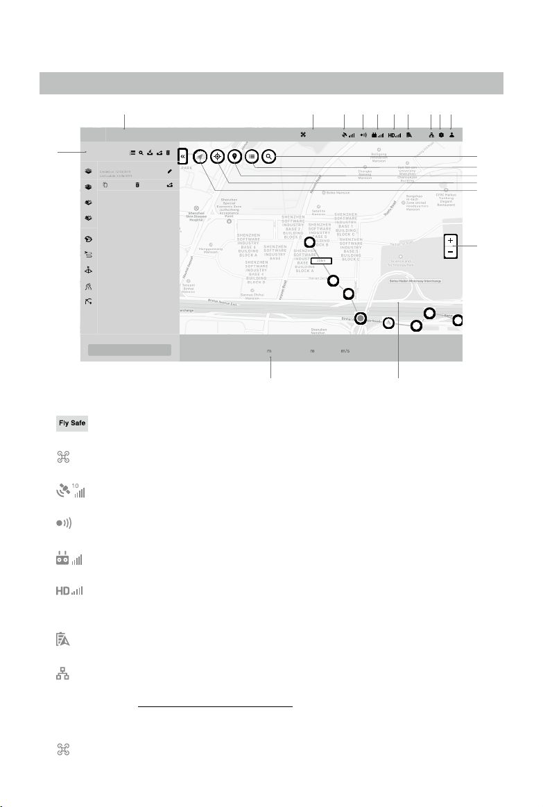
1. System Status Bar
: Indicates the aircraft ight status and displays various warning messages.
2. Aircraft Connection Status
: Shows the current connection status between DJI Terra and the aircraft.
3. GNSS signal Strength
: Shows the current GNSS signal strength and number of connected satellites.
4. Obstacle Avoidance System Status
: Shows if the obstacle avoidance system is functioning properly.
5. Remote Controller Signal Strength
: Shows the strength of the remote controller signal.
6. HD Video Link Signal Strength
: Shows the strength of the HD video downlink connection between the aircraft and
remote controller.
7. Aircraft Battery Level
100%
: Shows the current battery level.
8. Cluster Reconstruction Settings
: This icon will only appear when using DJI Terra Cluster. Click to enter the cluster
reconstruction settings to set the corresponding parameters and view cluster reconstruction
devices. Refer to “Cluster Reconstruction” on p. 51 for more information.
9. Settings
Click to enter the Settings menu.
: Flight Controller Settings — Includes RTH altitude, ight distance limit, altitude limit, etc.
Interface Introduction
Main Screen
1 2 3 4 5 76 98 10
16
12
11
13
14
15
19
1718
8
©
2021 DJI All Rights Reserved.
DJI TERRA
User Manual
: Gimbal and Camera Settings — Includes, photo quality, metering mode, etc.
: Remote Controller Settings — Includes customizing Button C1 and C2, selecting stick mode,
and switching the remote controller communication mode between PC mode and app mode.
: Obstacle Avoidance Settings — Enable or disable the obstacle avoidance function.
: General Settings — Includes length unit, area unit, language, cache directory, etc.
10. Account Information
: Log into/out of your account, activate license(s), check the unlocking license(s), version
number, read the privacy policy, and congure privacy data settings.
11. Search
: Input names to search on the map.
12. Self Mapping List
: Click to show a self mapping list. Choose a map or multi maps to display in the map view.
Maps will not display if not chosen.
13. Show/Hide GEO Zones
: Click to show or hide the DJI GEO Zones on the map.
14. Positioning
: If the aircraft is connected, click the icon to center the map around the aircraft’s location.
If the aircraft is disconnected, the map will be centered around the current network location. If
there is no available internet connection, it will be centered around the defaulted initial location
or the location when quitting from the software.
15. Map Mode
: Tap to switch bettwen Regular Map, Satellite Map, and Road Map.
16. Map Zoom
Click +/- to zoom in or out of the map.
17. Map View
Displays the map. Scroll the scroll wheel on the computer mouse to zoom in/out. Press and
hold the left button on the computer mouse to move the map.
18. Flight Telemetry
Home Distance: Horizontal distance from the Home Point.
Altitude: Vertical distance from the Home Point.
Speed: Movement speed across a horizontal distance.
Time: Aircraft operating time from motors started for the rst time.
Photo Count (Downloaded/Captured): In a Mapping mission, this function displays the photo
count downloaded from the aircraft to DJI Terra and the total number of photos captured.
The photos will be downloaded to DJI Terra only if Real-Time 2D Mapping or Real-Time 3D
Mapping is enabled. If it is disabled, by default the downloaded photo count is set to 0.
19. Mission Library
Missions will be assorted by types in mission library. Click each tag to display all missions of
the corresponding type. Click the arrow on the right of the library to collapse or expand it.
: Reconstruction Mission Management — Click to enter reconstruction mission
management to view the status of all reconstruction missions. When using cluster
reconstruction, users can also view the status of worker devices.
: Search — Click and input keywords in the text box to search a mission.
: Import — Click to import missions.
©
2021 DJI All Rights Reserved.
9
DJI TERRA
User Manual
: Export — Click to enter mission managing mode. Choose missions and export them.
The export function here is the same as the one mentioned below in the text about the export
function for a selected mission.
: Manage — Click to enter mission managing mode. Choose missions and delete them.
New Mission: Click to choose a mission type and create a new mission.
Click a mission to select it and:
: Edit — This icon can only be clicked before a mission starts. Click to enter mission editing
mode and set parameters.
: Continue — If a mission is stopped and “Back to Mission List” is chosen in the prompted
menu, this icon will appear when the same mission is selected in the mission library. Click to
choose the next operation from the prompted menu.
: View — This icon will appear after a mission is completed. Click to view the parameters.
NOTE: Parameters cannot be edited.
: Reconstruction — This icon will only appear in Reconstruction missions. The icon will
also appear in Flight Route missions if the reconstruction was created using DJI Terra v2.3.0
or earlier. Click to enter the reconstruction page for 2D map reconstruction or 3D model
reconstruction. For more information, refer to “Reconstruction Missions” on p. 30.
: Copy — Click to create a copy of this mission. The ight path and parameter settings will
be the same.
: Open Folder — Click to open the folder where the current mission is located.
: Delete — Click to delete the mission.
: Export — Click to export the mission with the current settings and its les such as photos,
2D maps, and 3D models. The exported file can be used to create a mission via “Import”.
The mission name of the exported mission is the same as the one in DJI Terra. It will not be
changed when importing it to create a mission even if the exported le’s name is changed.
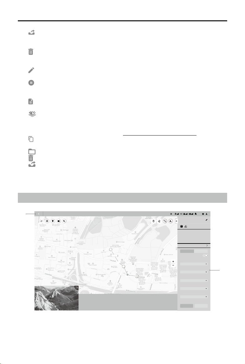
Flight Route Mission Editing View
1. Back
Click to return to the main screen.
S
2
56m
1234m
12m34s
90
100
100%
8BZQPJOUT
12
E
S
10 m/s
1IBOUPN
%%
/"
Route Distance
Waypoint Count Estimated Photo Count
New Waypoint Mission
Fly Safe
Route Settings Waypoint Settings
Coordinated Turn
Ratio
Camera
)PWFS
'PMMPX3PVUF
5JNFE4IPU
Finishing Action
Aircraft Heading
Capture Mode
Start Pause
0000
m
Home Distance
0000
m
Altitude
00.00
m
/s
Speed
00.00
Time
0
Photo Count (Downloaded/Captured)
Estimated Flight Route
Time
1
2
10
©
2021 DJI All Rights Reserved.
DJI TERRA
User Manual
2. Parameter List
This list includes the common screen elements below. The other settings vary according to
different mission types. Refer to Parameter Setting Introduction for details.
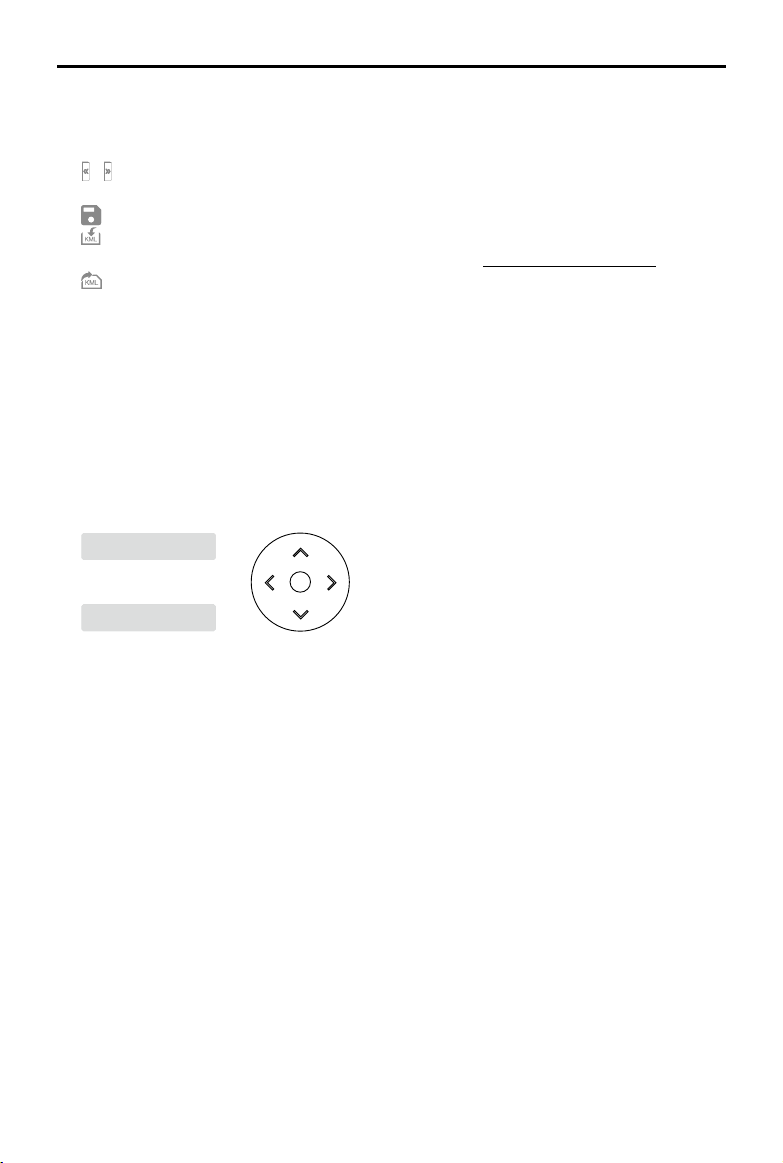
/ : Collapse / Expand — Click to collapse or expand the list.
Mission Name: Click the button on the right to edit the mission name.
: Save — Click to save current settings.
: KML Import — Click to import a KML le. The data in the KML le will be converted to waypoints
or edge points and displayed on the map for planning. Refer to “Create a Mission” on p. 11 for details.
: KML Export — This icon will appear only in Waypoints and Detailed Inspection missions.
Click to export the current flight route as a KML file. The exported file can be used to plan
the ight path in a Waypoints mission via “Import KML”. For KML les exported from Detailed
Inspection missions, users can also import the le into the Library in the DJI Pilot app to perform
the mission.
Mission Information: Information varies according to different mission types. These include:
route distance, estimated flight route time, estimated total flight route time, waypoint count,
cover area, estimated photo count, etc.
Sliders and -/+: Move to the left or right to adjust values. Click -/+ for ne-tuning.
Waypoint / Edge Point Edit:
114.20149139404
3
纬titude
22.70718090696
6
Longitude
Latitude
Click the box to input values. Click the arrow keys on the right for ne tuning. Up and down
adjust latitude while left and right adjust longitude.
Mission Button (aircraft connection is required):
a. Start: Click to start the mission after parameters are set.
b. Stop: During the mission, click to stop the mission. The aircraft hovers and records its
location as a breakpoint and users can control the aircraft manually. Users can then choose
an operation after stopping the mission from the prompted list in the software.
c. Pause / Continue: During a Waypoints mission, click to pause the mission, and the aircraft
will hover. Users can control the aircraft to y forward or backward along the ight path, but
the aircraft heading cannot be controlled. Click “Continue,” and the aircraft continues the
mission from its current position.
©
2021 DJI All Rights Reserved.
11
Flight Route Missions
Create a Mission
1. New Mission
Create a mission via the following two methods:
a. Click the “New Mission” button on the lower left corner, choose the mission type, input the
mission name, and then click “OK” to enter Mission Editing mode.
b. Click
in the right section of the mission library to import a mission le from the computer.
Click to select the imported mission and then click
to enter Mission Editing mode. The
imported mission cannot be edited, if it has already been nished before export.
2. Mission Settings
For a Detailed Inspection mission, there will be a prompt for route planning instructions after a
mission is created to guide users throughout the basic procedure. Click “OK” after reading the
instructions and enter the Mission Settings page to edit the mission name, select aircraft and
desired model. The list in this page will list the models from 3D reconstruction results using DJI
Terra. Users can also click “Import Point Cloud” to import third-party LAS point cloud les as the
model to use. After conguration, click “OK” to enter Mission Editing mode.
Make sure that the accuracy of the imported models or point clouds meets the operation
requirements.
3. Plan Flight Path
Waypoints missions are flight paths with waypoints. When using a Phantom 4 RTK aircraft,
the waypoint quantity should not exceed 199. While using other aircraft, the waypoint quantity
should not exceed 99.
For Mapping missions or Oblique missions, DJI Terra automatically generates ight paths after
the user has set their required ight area and parameters.
For Corridor missions, DJI Terra automatically creates a ight area extending from the center line
and generates ight paths after the user has set their required corridor points and parameters.
Add points via the following methods:
a. Click on the map to add a point.
b. Fly the aircraft to the desired position and then click
on the upper right corner to set the
aircraft position as a point.
c. Click
in the parameter list to import a KML le. The data in the le will be converted to
points and displayed on the map. This is a premium function included in DJI Terra Pro and
more advanced versions. Please purchase a license and then activate it before use. For
more information related to purchase and activation, refer to “More Functions” on p. 50.
For Waypoints missions, users can plan ight paths based on a 2D map, 3D model or point
cloud generated in DJI Terra. Make sure that there is no waypoint added, then click
on the
right of the 2D/3D section in the parameter list, select a desired 2D map or 3D model, and click
“Import.” The imported map or model will be displayed in the map view. Add waypoints based
on the 2D map or 3D model using the above methods.
12
©
2021 DJI All Rights Reserved.
DJI TERRA
User Manual
The functions for importing 2D maps or 3D models, ight path planning based on a 2D map, and
ight path planning based on a 3D model (called “3D Mission Planning” in a Waypoints mission)
are included in the DJI Terra Pro and more advanced versions. Please purchase a license and
then activate it before use. For information related to purchase and activation, refer to “More
Functions” on p. 50.
During 3D mission planning, waypoints can only be added when the 3D model is
displayed in top view. Click
to switch to the top view automatically.
For a Detailed Inspection mission, click on the model to add a target point, and then congure the
parameters. DJI Terra will generate its corresponding waypoint. All the waypoints make up the
ight path. When using a Phantom 4 RTK aircraft, the waypoint quantity should not exceed 199.
4. Edit Points
Click a point to select it and the selected point will turn from white to blue. Drag the point to
change the area shape or flight path (except Detailed Inspection missions). In a Mapping
mission or Oblique mission, click on the map, and a new point will be added between the two
points. These points will be situated near the location you have clicked on.
For a Detailed Inspection mission, click the target point to select it and the selected point will
turn from green to red. Drag the target point to change its position. Select a waypoint or target
point, then click the desired position for a new target point on the model, and a new point will be
added between the selected point and its next point.
Other operations can also be performed via the buttons below:
: Delete selected waypoint/edge point — Click a point to select it and it will turn to blue. Then
click this button to delete it.
: Delete all waypoints/edge points — Click to delete all the waypoints or edge points in this
mission.
S
E
: Switch start and endpoints — Click to swap the start and endpoints to reverse the ight
path.
: Set your aircraft’s current position as a waypoint/edge point — Click to set the aircraft
position as a waypoint or edge point.
During 3D Mission Planning, hold down the mouse wheel and drag to adjust the display view
of the 3D model, and different icons will be displayed on the selected waypoint to indicate the
directions in which this waypoint can be adjusted.
indicates that the position in horizontal
direction can be adjusted, and
indicates that the position in vertical direction can be
adjusted. Drag the waypoint in the corresponding direction to adjust its position. The image
of viewing the model from the selected waypoint’s perspective is displayed on the lower right
corner on the screen.
Edge points of a ight area should not be too close. Otherwise, it will fail to generate
ight path.
The above requirements are also applicable when importing a KML le to plan a ight
path.
©
2021 DJI All Rights Reserved.
13
DJI TERRA
User Manual
There are different limits depending on the models of the aircraft when planning and
editing a Waypoint mission.
For Phantom 4 RTK, Phantom 4 Pro+ V2.0, and Phantom 4 Pro V2.0 aircraft: The
distance between two waypoints should not exceed 200 km. The total distance of the
ight path has no limits.
For Phantom 4 Pro+, Phantom 4 Pro, Phantom 4 Advanced, and Phantom 4 aircraft:
The distance between two waypoints should not exceed 2 km. The total distance of
the ight path cannot exceed 40 km.
For a Detailed Inspection mission, users can also perform the operations below.
/ : To display or hide the target name. When the target name is displayed, click the text
box near the target point on the map to edit its name.
In the 3D model view, hold down the mouse wheel and drag to adjust the display view of the
3D model. Click the buttons on the right of the screen to adjust the display of the 3D model in
specic views and to zoom in or out.
In “Waypoint Settings”, edit and congure each waypoint separately. Refer to “Parameter Setting
Introduction” on p. 15 for more details.
5. Parameter Settings
Set each item in the parameter list and click to save when complete. Refer to “Parameter
Setting Introduction” on p. 15 for more details.
Perform Mission
For a Detailed Inspection mission, if the Phantom 4 RTK aircraft is selected in the Mission Settings,
import the ight route KML le to a Waypoints mission in DJI Terra or import the le into Library in
DJI Pilot to perform the mission. If the Matrice 300 RTK aircraft is selected, to perform the mission,
the ight route KML le can only be imported into Library in DJI Pilot.
To perform the mission using KML les exported from Detailed Inspection missions, aircraft
rmware and DJI Pilot app of the corresponding version are required. Pay attention to the
release notes of the related products.
Before performing the mission, make sure that the aircraft positioning is in the RTK FIX
status to avoid accidents.
For other missions, follow the descriptions below.
Start Mission
1. Select a mission in the mission library. Click “Edit” and then click “Start.” A ight preparation list
will appear.
2. Wait for the ight path to upload to the aircraft. Check and adjust the aircraft according to the list
that appears until all items are green, indicating that takeoff is permitted. Items in yellow require
adjustment, but the aircraft can take off without doing so. Only ying when all items are green is
highly recommended.
3. Click “Start.” The aircraft will y along the pre-set ight path to perform the mission.

14
©
2021 DJI All Rights Reserved.
DJI TERRA
User Manual
4. In a Mapping mission, if Real-Time 2D Mapping or Real-Time 3D Mapping is enabled, the real-
time mapping result will display on the map during the mission as follows:
a. The aircraft ies to the starting point of the ight path and start shooting.
b. When photo count (shown in the ight telemetry at the bottom of the screen) is more than 10, the
real-time mapping pictures or 3D point cloud will be shown at the corresponding position on the
map. No picture display may be due to the map display level. Zoom in or out to view the result.
c. As the mission progresses, the mapping result of the ight area will be shown on the map
gradually.
Stop Mission
During a mission, click the “Stop” button on the screen and the aircraft will hover in place and
record the current position as a breakpoint. The aircraft can then be own freely and a menu will
pop up with additional control options. In a Mapping mission, the pop-up menu display will vary
depending on whether “Real-Time 2D Mapping” or “Real-Time 3D Mapping” is enabled.
Real-Time 2D Mapping or Real-Time 3D Mapping Enabled
Click the “Stop” button, and there will be a prompt indicating that real-time 2D mapping or real-time
3D mapping is paused. Click “OK”, and then choose from the options below.
Resume from break point: The aircraft will continue the mission from the recorded breakpoint.
End Current Mission and Start Image Processing: The aircraft will stop the current mission, and DJI Terra
will start post-processing for the captured photos to reconstruct a 2D map or 3D point cloud/model.
Cancel Mission: The aircraft will stop the mission. DJI Terra will not process the photos.
Real-Time 2D Mapping or Real-Time 3D Mapping Disabled
Click the “Stop” button, and then choose from the options below.
Save waypoint route info and mission status: DJI Terra will save the breakpoint information and exit
from the current mission.
Cancel Mission: The aircraft will stop and exit from the current mission. The mission cannot be
continued.
If “Save waypoint route info and mission status” is chosen, users can select from the list below as
required after connecting the aircraft and entering the same mission again:
Resume from break point: The aircraft will continue the mission from the recorded breakpoint.
Resume from previous waypoint: The aircraft will continue the mission from the previous waypoint
before the recorded breakpoint.
Resume from next waypoint: The aircraft will continue the mission from the next waypoint after the
recorded breakpoint.
Restart: The aircraft will y to the start point and restart the mission.
Cancel Mission: DJI Terra will clear the recorded breakpoint information in the current mission and
exit from the mission.
Back to Mission List: Back to the mission library. To check this menu again, select the required
mission and click “Continue”.
Special Cases
1. During any mission, the aircraft will exit from its mission and enter a normal flight mode if
positioning is not available due to a weak GNSS signal. Users can choose to continue the mission
if the signal is strong. When continuing, the aircraft will continue from its last recorded point.
©
2021 DJI All Rights Reserved.
15
DJI TERRA
User Manual
2. Smart Low-Battery Level: When there is only sufcient battery level for RTH, an audio prompt will
emit from the remote controller. After a few seconds, the aircraft will stop the mission and begin
RTH. Users can cancel the RTH by pressing the Smart RTH button on the remote controller.
The mission can be continued and the aircraft will continue the mission from the point where
recording stopped after replacing battery.
3. Low Battery Level / Critically Low Battery Level: When the battery level is lower than the Low
Battery value pre-set in the app*, an audio prompt will sound from the remote controller. When
the battery level is lower than the Critically Low Battery value pre-set in the app, an audio prompt
will sound from the remote controller. The aircraft will stop the mission and land automatically.
The mission can be continued and the aircraft will continue the mission from the point where
recording stopped after replacing battery.
* App refers to all the apps used with the aircraft, for example DJI GO 4.
Mission Complete
After nishing a mission, the aircraft will perform the pre-set “Finishing Action.” The aircraft can be
controlled freely afterward.
For a Mapping mission:
If Real-Time 2D Mapping or Real-Time 3D Mapping is enabled, DJI Terra will enter post-processing
stage after mission completion to process the captured photos again for mapping result of higher
accuracy with more zoom levels. After post-processing completion, users can zoom in to view the
more accurate result.
If the option is disabled, after mission completion, users can create a Reconstruction mission to
process the captured photos for reconstruction. Refer to “Reconstruction Missions” on p. 30 for details.
Parameter Setting Introduction
Select a mission in the mission library. Click “Edit” to enter mission editing mode for parameter
settings.
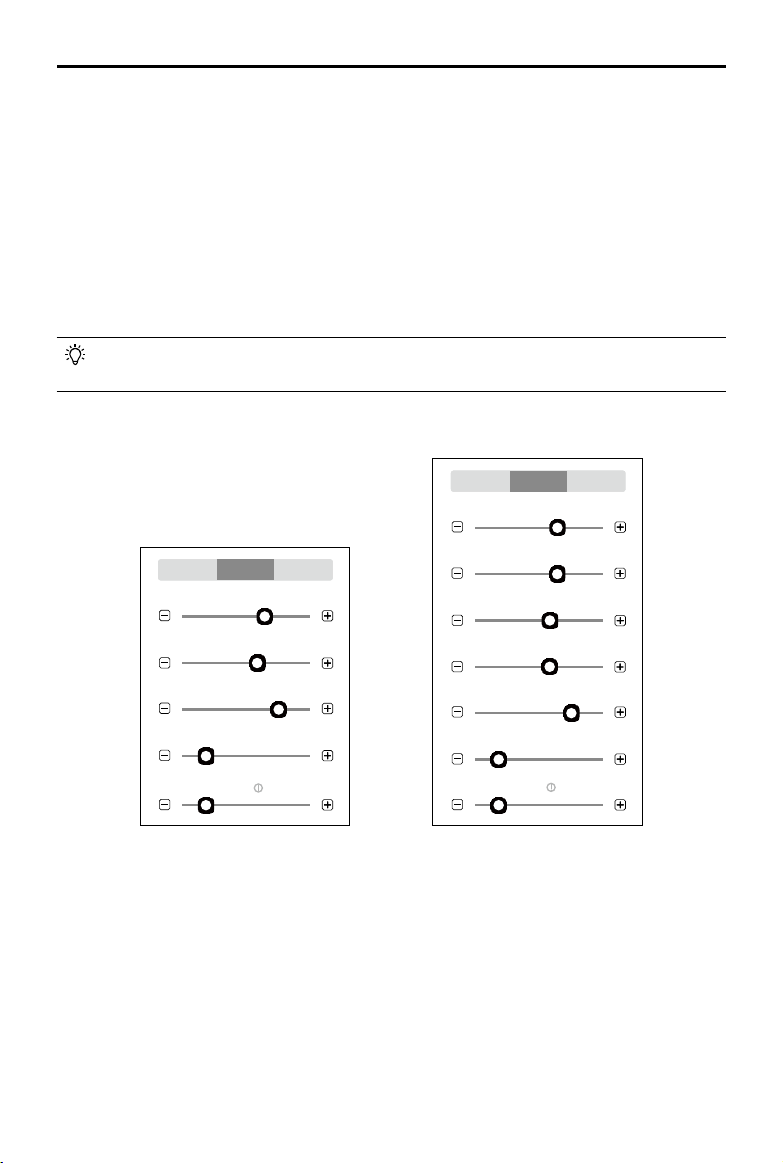
Waypoints Settings
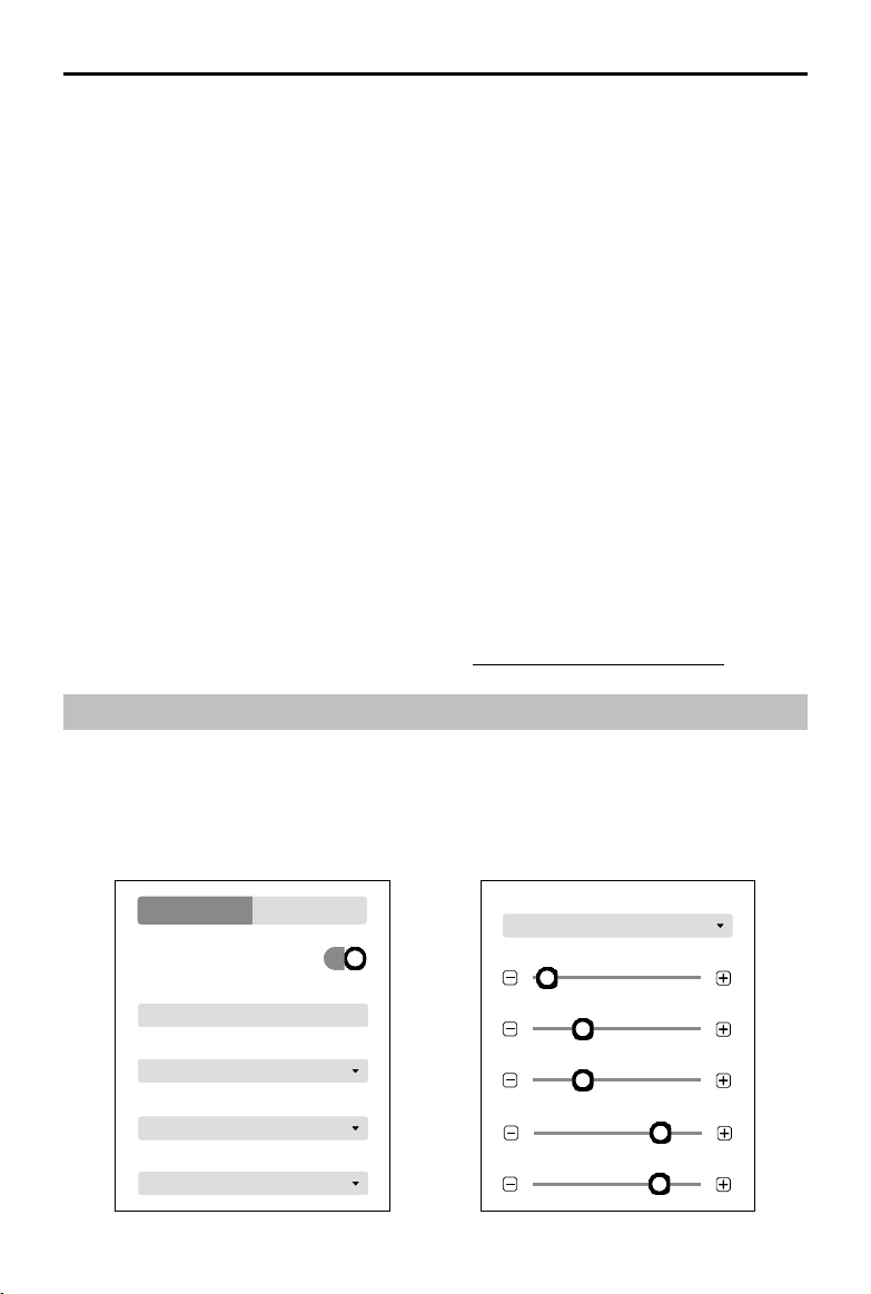
Route Settings
Route Settings Waypoint Settings
Coordinated Turn
Phantom 4
Camera
4: 3
Ratio
Hover
Finishing Action
10 m/s
Initial Speed
100 m
Route Altitude
4 m/s
Route Speed
-20°
Gimbal Pitch Angle
2.5 s
Interval
Timed Shot
Capture Mode
Follow Route
Aircraft Heading
Route Settings Waypoint Settings
Coordinated Turn
Phantom 4
Camera
4: 3
Ratio
Hover
Finishing Action
10 m/s
Initial Speed
100 m
Route Altitude
4 m/s
Route Speed
-20°
Gimbal Pitch Angle
2.5 s
Interval
Timed Shot
Capture Mode
Follow Route
Aircraft Heading
16
©
2021 DJI All Rights Reserved.
DJI TERRA
User Manual
1. Coordinated Turn
If enabled, the aircraft will y on a smooth curve when passing a waypoint. Set a “Turn Radius”
in “Waypoint Settings.” However, be aware that only Waypoint Actions on the start and
endpoints will be performed, while the Waypoint Actions on other points will not.
If disabled, the aircraft will fly to a waypoint and perform Waypoint Actions. If no Waypoint
Actions are set on a waypoint, the aircraft will stop at the waypoint, adjust its heading and y to
the next waypoint.
2. Camera
DJI Terra can recognize the camera model of the aircraft. Unless otherwise specied, users
don’t need to set it.
3. Ratio
Refers to the ratio of the width and height of the photos captured during the mission.
4. Finishing Action
Aircraft action after mission complete.
Hover: The aircraft will hover at the nal waypoint after mission completion. Then users can then
control the aircraft directly.
Return to Home: If the aircraft altitude is higher than this pre-set value, it will return to home at its
mission completion altitude. If the aircraft altitude is lower than the pre-set value it will ascend to
the RTH altitude after mission completion before returning to home. The RTH altitude can be set
in Flight Controller Settings.
Land: The aircraft will land at the final waypoint and stop motors automatically after mission
completion.
Return and Hover: The aircraft will return to the starting point of the flight path and hover after the
mission is complete. The altitude when returning to the starting point is the same as RTH altitude.
Make sure that the endpoint of the ight path is suitable for landing when nishing action is
set to “Land” to avoid potential ight accidents.
5. Aircraft Heading
Aircraft heading when performing the mission.
Follow Route: The aircraft’s nose is always aligned to the direction of the next two waypoints.
Set Waypoint Separately: Set aircraft heading at each waypoint in “Waypoint Settings”.
6. Capture Mode
Waypoint Hovering Shot: The aircraft will hover and capture at each waypoint. In this mode,
shooting is stable, but the time required will be long. The number of waypoints required may be
large, which will also make mission times longer.
Timed Shot: The aircraft will capture in a xed time interval as it ies along the path. The aircraft
will not hover during capturing unless there is a waypoint action. Users can set the time interval.
In this mode, operation is fast. However, short exposure times are required.
7. Interval
This setting will appear when capture mode is set to Timed Shot.
©
2021 DJI All Rights Reserved.
17
DJI TERRA
User Manual
8. Route Altitude
The relative altitude between the aircraft and the takeoff point during ight. This can be set from
0 to 500 m. You can also set the altitude of each waypoint in “Waypoint Settings”.
During 3D mission planning, the altitude at each waypoint is the relative altitude between the
aircraft and the scene in the 3D model below the corresponding waypoint.
9. Route Speed
The ight speed when ying along a waypoint ight path.
10. Initial Speed
Flight speed when not ying along the waypoint-determined ight path. This includes the ight
speed from the aircraft position to the starting point of the ight path when starting a mission,
or returning speed after mission completion.
11. Gimbal Pitch Angle
The gimbal pitch angle at the selected waypoint. Pitch angle can range from -90° to 0°, with
downward represented by -90° and forward represented by 0°.
If capture mode, route speed, or gimbal pitch angle are set in “Route Settings,” the capture
mode, speed, or gimbal pitch angle setting in “Waypoint Settings” will automatically change
to the same as the one in “Route Settings.”
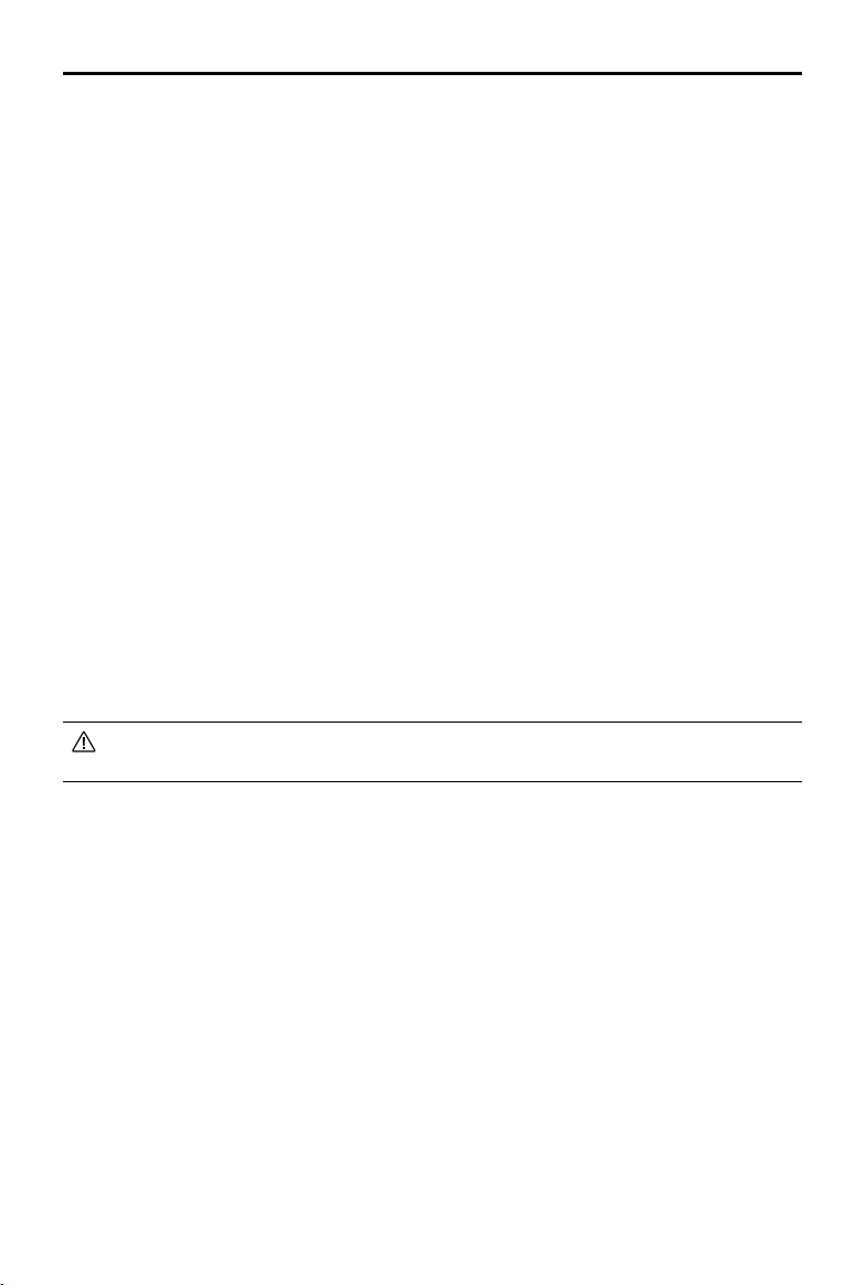
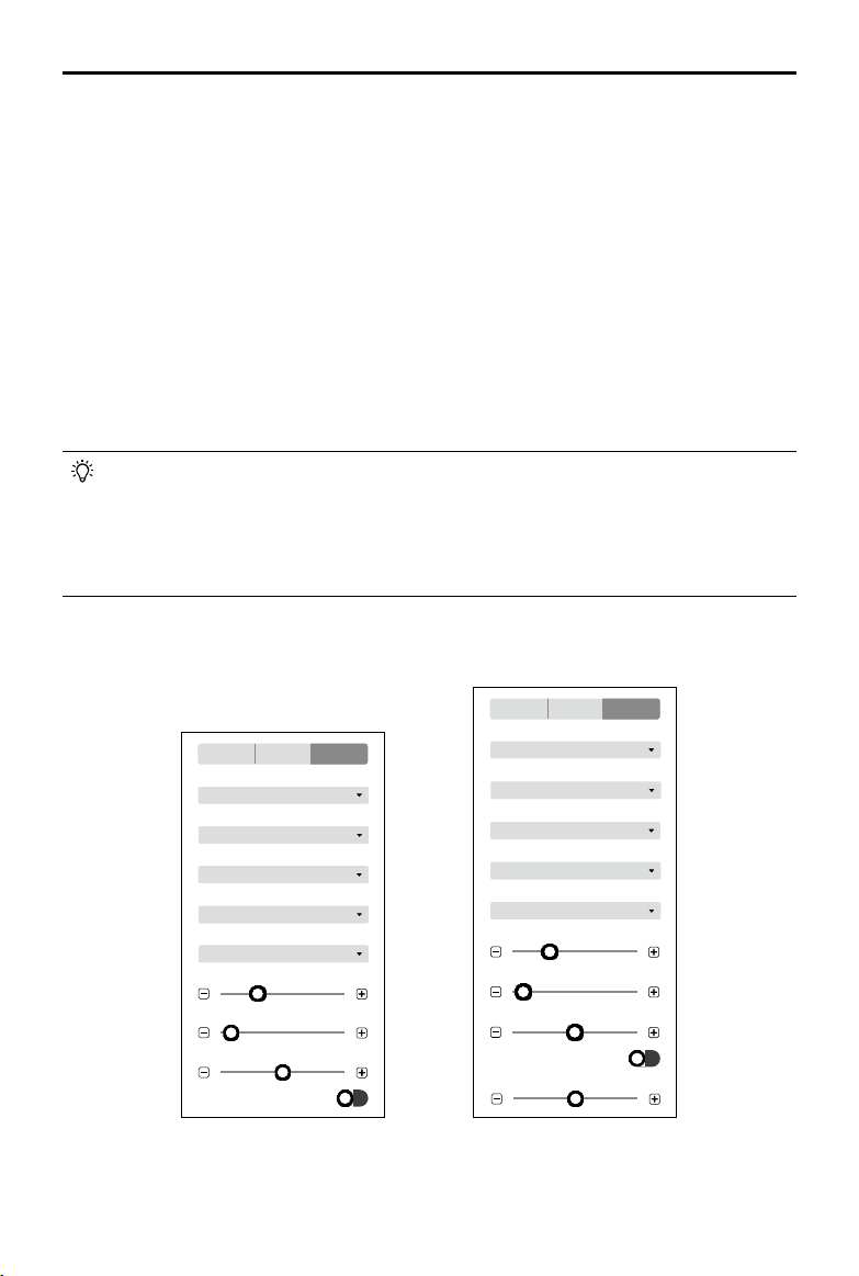
Waypoint Settings
Gimbal Pitch Angle
Waypoint 01
Route Settings Waypoint Settings
2.5 s
Interval
Min Angle
Turning Mode
Timed Shot
Capture Mode
10 m/s
Speed
100 m
Altitude
-20°
8.2 m
Turn Radius
Action 0 Action(s)
Gimbal Pitch Angle
Waypoint 01
Route Settings Waypoint Settings
2.5 s
Interval
Min Angle
Turning Mode
Timed Shot
Capture Mode
10 m/s
Speed
100 m
Altitude
-20°
8.2 m
Turn Radius
Action 0 Action(s)
Select a waypoint (it will turn blue when selected) then set waypoint parameters. Click or to
switch to the previous or next waypoint. The keyboard shortcut “Ctrl+ ← ” or “Ctrl+ → ” can also be
used to switch accordingly.
1. Capture Mode
Waypoint Hovering Shot: The aircraft will hover and capture at the selected waypoint.
Time Shot: The aircraft will capture in a xed time interval as it ies from the selected waypoint to
the next waypoint. The aircraft will not hover during capturing. Users can set the time interval.

18
©
2021 DJI All Rights Reserved.
DJI TERRA
User Manual
2. Turning Mode
The aircraft rotation direction when ying to the next waypoint. This option will be available only if
“Set Waypoint Separately” is set for “Aircraft Heading” in “Route Settings”. “Min Angle” and “Max
Angle” respectively indicate that the aircraft will rotate in the direction with a min or max rotation
angle to adjust its heading to the pre-set value of the next waypoint.
3. Interval
This setting will appear when capture mode is set to Timed Shot.
4. Altitude
Set the relative altitude of each waypoint between the aircraft and the takeoff point. The range
can be set from -120 m to 500 m with a negative value lower than the takeoff point and a positive
value higher than the takeoff point. When the altitude of the start point is set to a negative value,
indicating that the start point is lower than the takeoff point, make sure to click
for the setting,
read and comply with the warning message: To ensure ight safety, when the altitude of the rst
waypoint is lower than the takeoff point altitude, y the aircraft to an obstacle-free environment
before starting the ight mission.
During 3D mission planning, the altitude at each waypoint is the relative altitude between the
aircraft and the scene in the 3D model below the corresponding waypoint.
5. Speed
The aircraft will ascend/descend to the ight speed set here when ying to the selected waypoint
and then contitues ying at this speed. The range can be set from 0.2 to 13 m/s.
6. Gimbal Pitch Angle
The gimbal pitch angle at the selected waypoint. Pitch angle can range from -90° to 0°, with
downward represented by -90° and forward represented by 0°. The gimbal will tilt gradually
to the angle pre-set at the next waypoint if the values at the two consecutive waypoints are
different.
7. Turn Radius
This is the aircraft’s turn radius when ying past a waypoint. Radius can range from 0.2 to 1000 m.
This option will be available only if “Coordinated Turn” is enabled in “Route Settings”. Note that
the “Turn Radius” setting is unavailable for start and stop points, and the sum of the turn radius
of two neighboring waypoints should not exceed the distance between the two waypoints.
8. Action
Click to enter. Up to 15 actions can be added. Delete actions or re-order them.
Add Actions: Click to add. Actions will be performed in the order they are added unless re-
ordered.
a. Hover: The aircraft will hover at the waypoint. Set hovering time from 0 to 30000 ms.
b. Capture: Capture on arrival at a waypoint. Note that Capture cannot be performed if the
camera is recording.
c. Start Recording: Start recording on arrival at a waypoint.
d. Stop Recording: Stop recording on arrival at a waypoint.
e. Aircraft Heading: Adjust the aircraft heading on arrival at a waypoint. North is 0° with a
negative value representing clockwise and the range is -180° to 180°.
©
2021 DJI All Rights Reserved.
19
DJI TERRA
User Manual
f. Gimbal Pitch: Adjust the gimbal pitch angle on arrival at this waypoint. Pitch angle can range
from -90° to 0°, with downward represented by -90° and forward represented by 0°. If “Gimbal
Pitch Angle” is set as a value in “Waypoint Settings”, the aircraft will y to the waypoint with
the dened Gimbal Pitch Angle then adjust it according to the Gimbal Pitch settings dened
when adding an Action for the current waypoint.
Delete Action: Click
on the right side of the desired action to delete it.
Re-Order: Click and hold
on the left side of the desired action, drag it to the desired position
and release.
DO NOT add Start Recording after Capture. Otherwise recording cannot be started.
DO NOT add Capture after Stop Recording. Otherwise a picture cannot be captured.
Mapping / Oblique Settings
The settings for Mapping and Oblique missions are similar. Unless otherwise specified, the
descriptions below are compatible with both types of missions.
For Oblique missions, parameters such as overlap ratio and speed can be set separately for the
nadir view ight path and oblique ight paths. During mission settings, click the numbers 1 to 5 in
the map view to preview each ight path. 1 refers to the nadir view ight path, and 2 to 5 refer to the
four oblique ight paths respectively.
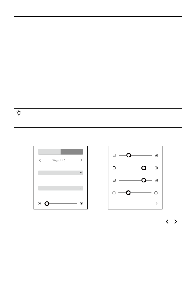
Basic Settings
Mapping
Basic Advanced Camera
Real-Time 2D Mapping
Real-Time 3D Mapping
2.74 cm/pixelGSD
Field
Mapping Scenes
Return to Home
Finishing Action
100 m
Mission Altitude
10 m/s
Speed
Max. Speed 13m/s Set
10 m/s
2.74 cm/pixelGSD
Max. Speed 13m/s Set
Max. Speed 13m/s Set
Return to Home
Finishing Action
100 m
Mission Altitude
10 m/s
Speed (Nadir View)
Speed (Oblique)
Basic Advanced Camera
Select Flight Route
Route 1
Route 2
Route 3
Route 5
Route 4
Oblique
Basic Advanced Camera
Real-Time 2D Mapping
Real-Time 3D Mapping
2.74 cm/pixelGSD
Field
Mapping Scenes
Return to Home
Finishing Action
100 m
Mission Altitude
10 m/s
Speed
Max. Speed 13m/s Set
10 m/s
2.74 cm/pixelGSD
Max. Speed 13m/s Set
Max. Speed 13m/s Set
Return to Home
Finishing Action
100 m
Mission Altitude
10 m/s
Speed (Nadir View)
Speed (Oblique)
Basic Advanced Camera
Select Flight Route
Route 1
Route 2
Route 3
Route 5
Route 4
1. Real-Time 2D Mapping (for Mapping only)
If enabled, DJI Terra will process the photos captured during a mission and display the mapping
results on the map in real time. However, the results will be less accurate. Users can import the
original photos into DJI Terra after the mission is complete for mapping with higher accuracy.
If disabled, there will not be any real-time results.
20
©
2021 DJI All Rights Reserved.
DJI TERRA
User Manual
2. Real-Time 3D Mapping
This is a premium function. Please purchase a license and then activate it before use. For more
information, refer to “More Functions” on p. 50.
If enabled, DJI Terra will process the photos captured during a mission and display the 3D point
cloud results on the map in real time. Users can import the original photos into DJI Terra after
the mission is complete for 3D model reconstruction with higher accuracy. The default real-time
3D mapping results include both the point cloud and model results. The real-time model results
can be removed by unchecking the model option box.
If disabled, there will not be any real-time results.
Real-time 3D mapping is only available when using the Phantom 4 RTK, Phantom 4 Pro
V2.0+ or Phantom 4 Pro V2.0 aircraft. The real-time 2D mapping and real-time 3D mapping
cannot be enabled simultaneously.
3. Mapping Scenes (for Mapping only)
Choose mapping scenes such as eld and urban according to application requirements. It is
recommended to choose eld in open areas where objects have a minor difference in height.
Use urban for surroundings with more buildings. The urban option is included in DJI Terra Pro
and more advanced versions. Please purchase a license and then activate it before use. For
more information, refer to “More Functions” on p. 50.
4. Finishing Action
Aircraft action after mission complete.
Hover: The aircraft will hover at the nal waypoint after mission completion. Then users can then
control the aircraft directly.
Return to Home: If the aircraft altitude is higher than this pre-set value, it will return to home at its
mission completion altitude. If the aircraft altitude is lower than the pre-set value it will ascend to the
RTH altitude after mission completion before returning to home. The RTH altitude can be set in Flight
Controller Settings.
Land: The aircraft will land at the final waypoint and stop motors automatically after mission
completion.
Make sure that the end point of the ight path is suitable for landing when nishing action is
set to “Land” to avoid potential ight accidents.
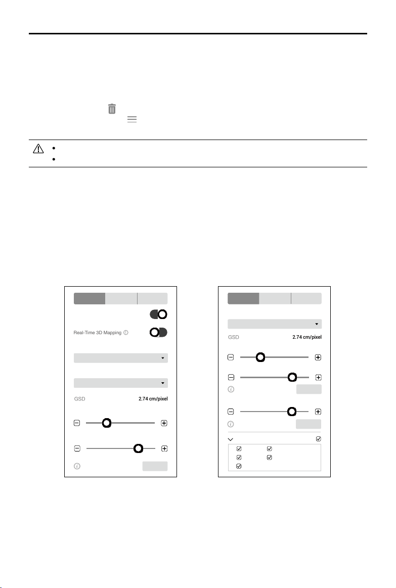
5. GSD
Ground Sample Distance. This value is the actual ground distance represented by each pixel
in the original image captured, and is automatically calculated by DJI Terra based on the ying
altitude and camera model.
6. Mission Altitude
The relative altitude between the aircraft and the area being mapped.
7. Speed / Speed (Nadir View) / Speed (Oblique)
The ight speed of the aircraft during mission. When ying out of the ight path such as ying
from the current position to the starting point when mission starts, or ying back after mission
completion, the ight speed will be 13 m/s, which cannot be customized.
©
2021 DJI All Rights Reserved.
21
DJI TERRA
User Manual
For Oblique missions, “Speed (Nadir View)” refers to the speed at which the aircraft is ying
along the nadir view ight path. “Speed (Oblique)” refers to the speed at which the aircraft is
ying along the oblique ight paths.
8. Max Speed
DJI Terra will calculate a maximum ight speed at which images meeting mapping requirements
can be captured according to the altitude, camera model, and advanced settings. Click “Set” to
set the ight speed to this max speed.
9. Select Flight Route
Check the corresponding box to select the desired ight route. The unchecked ight route will
not be executed.
For Oblique missions, if required, users can adjust the location of the start point for each
ight route after planning the routes. Click the start point or end point to switch the two.
Advanced Settings
74%
Forward Overlap Ratio
Side Overlap Ratio (Oblique)
66%
74%
66%
287º
-13 m
30 m
Basic Advanced Camera
Basic Advanced Camera
Side Overlap Ratio
Forward Overlap Ratio
Course Angle
Mission Relative Height
Margin
74%
Side Overlap Ratio
66%
Forward Overlap Ratio (Oblique)
287º
Course Angle
30 m
Mission Relative Height
-13 m
Margin
Mapping
74%
Forward Overlap Ratio
Side Overlap Ratio (Oblique)
66%
74%
66%
287º
-13 m
30 m
Basic Advanced Camera
Basic Advanced Camera
Side Overlap Ratio
Forward Overlap Ratio
Course Angle
Mission Relative Height
Margin
74%
Side Overlap Ratio
66%
Forward Overlap Ratio (Oblique)
287º
Course Angle
30 m
Mission Relative Height
-13 m
Margin
Oblique
1. Side Overlap Ratio / Side Overlap Ratio (Oblique)
The overlap ratio of two pictures on two parallel main paths. The range can be set from 10% to
90%.
For Oblique missions, “Side Overlap Ratio” refers to the overlap ratio for the nadir view ight
path, and “Side Overlap Ratio (Oblique)” refers to the overlap ratio for the oblique ight paths.
2. Forward Overlap Ratio / Forward Overlap Ratio (Oblique)
The overlap ratio of two consecutive pictures captured along the same main path. The range
can be set from 10% to 90%.
22
©
2021 DJI All Rights Reserved.
DJI TERRA
User Manual
For Oblique missions, “Forward Overlap Ratio” refers to the overlap ratio for the nadir view ight
path, and “Forward Overlap Ratio (Oblique)” refers to the overlap ratio for the oblique flight
paths.
3. Course Angle
The angle of the main path. North is 0°, with a positive value when it is clockwise. The range can
be set from 1° to 360°.
4. Margin
Expand (positive value) or narrow (negative value) the area margin for control over the area of
ight. The range can be set from -30 to +30m.
5. Mission Relative Height
The relative height between the takeoff point and the area being mapped.
NOTE: Make sure to set the correct relative height. Otherwise, the overlap ratios will be affected
which may have a negative effect on the mapping results.
Users can adjust the overlap ratios, altitude, and gimbal pitch angle (for Oblique mission
only) according to actual situations. Reduce overlap ratio accordingly for areas with less
terrain uctuations. Increase overlap ratio accordingly for areas with more terrain uctuations.
However, it is recommended to set a side overlap ratio of no less than 60% and a forward
overlap ratio of no less than 65%. For objects that require highly detailed results, create
multiple missions to cover more perspectives of the desired area or object.
Camera Settings
100
ISO
Undistortion
Basic Advanced Camera
Phantom 4 RTK
Camera
4:3
Ratio
Field
White Balance
S
Exposure Mode
Customize
Exposure Scenes
400
Shutter
Undistortion
100
ISO
-0.3
Exposure Compensation
-0.3
Exposure Compensation
Phantom 4 RTK
Camera
4:3
Ratio
400
Shutter
-50°
Gimbal Pitch Angle
White Balance
Field
Exposure Mode
S
Exposure Scenes
Customize
Basic Advanced Camera
Mapping
100
ISO
Undistortion
Basic Advanced Camera
Phantom 4 RTK
Camera
4:3
Ratio
Field
White Balance
S
Exposure Mode
Customize
Exposure Scenes
400
Shutter
Undistortion
100
ISO
-0.3
Exposure Compensation
-0.3
Exposure Compensation
Phantom 4 RTK
Camera
4:3
Ratio
400
Shutter
-50°
Gimbal Pitch Angle
White Balance
Field
Exposure Mode
S
Exposure Scenes
Customize
Basic Advanced Camera
Oblique

©
2021 DJI All Rights Reserved.
23
DJI TERRA
User Manual
1. Camera
DJI Terra can recognize the camera model of the aircraft. Unless otherwise specified, users
don’t need to set it.
2. Ratio
Set the photo ratio of the photos captured during the mission. 4:3 is recommended.
3. Balance
Field is set by default. Users can select other options according to the application.
4. Exposure Mode
Choose from Auto or S (shutter priority). If S is set, choose from Sunny, Cloudy, Low light, and
Customize for the Exposure Scenes setting. If Customize is set, users can adjust shutter, ISO,
and exposure compensation.
5. Undistortion
This option will appear when using the Phantom 4 RTK. It is disabled by default. If enabled, the
software can automatically correct the distortion when capturing, but the quality of the photos
captured may be lower than the photo quality when this option is disabled. It is recommended to
disable this option when original photos are needed for post processing.
6. Gimbal Pitch Angle (for Oblique only)
The gimbal pitch angle at which the aircraft is ying along the oblique ight path. The range for
the gimbal pitch angle can be set from -85° to -40°.
Corridor Settings
Select Flight Route
Route 1
Route 2
Return to Home
Finishing Action
2.74 cm/pixelGSD
100 m
Mission Altitude
Max. Speed 13m/s Set
10 m/s
Speed
Basic Advanced Camera
Basic Advanced Camera
Route Preview
Include center line?
Expansion Distance to Left
31 m
Expansion Distance to Right
31 m
Flight Band Cutting Distance
2000 m
Adjust expansion distance
at the same time?
Yes
Basic Settings
1. Route Preview
When enabled, the ight route generated according to the current settings can be previewed on
the map. During route preview, users cannot edit the corridor points on the center line.

24
©
2021 DJI All Rights Reserved.
DJI TERRA
User Manual
2. Include center line
To set if the center line will be included the ight paths generated. The center line refers to the
line consisting of the corridor points added when planning the Corridor mission.
3. Adjust expansion distance at the same time
To set if expansion distance for both sides will be adjusted at the same time. If yes, the
expansion distance for one side will follow the adjustment for the other side. If no, each
expansion distance can be adjusted separately.
4. Expansion Distance to Left/Right
To adjust the expansion distance to left or right for the corridor ight area. Left or right refer to
the left or right side of the center line when the front direction is dened by the line from one of
the corridor points pointing to its previous point.
5. Flight Band Cutting Distance
DJI Terra will divide corridor ight areas with a long center line into multiple segments according
to this ight band cutting distance. Each segment has a sub mission with an independent ight
route. Users can check the corresponding box in the Select Flight Route setting at the bottom of
the screen to select the desired ight route before performing the mission. Click the area of each
sub mission to view the mission information. For each sub mission, a starting point, end point,
and several white points will be displayed on the map. Click one of these points to set it as the
starting point of the sub mission ight route.
6. GSD
Ground Sample Distance. This value is the actual ground distance represented by each pixel
in the original image captured, and is automatically calculated by DJI Terra based on the ying
altitude and camera model.
7. Mission Altitude
The relative altitude between the aircraft and the area being mapped.
8. Speed
The ight speed of the aircraft during mission. When ying out of the ight path such as ying
from the current position to the starting point when mission starts, or ying back after mission
completion, the ight speed will be 13 m/s, which cannot be customized.
9. Max Speed
DJI Terra will calculate a maximum ight speed at which images meeting mapping requirements
can be captured according to the altitude, camera model, and advanced settings. Click “Set” to
set the ight speed to this max speed.
10. Finishing Action
Aircraft action after mission complete.
Hover: The aircraft will hover at the nal waypoint after mission completion. Then users can
then control the aircraft directly.
Return to Home: If the aircraft altitude is higher than this pre-set value, it will return to home
at its mission completion altitude. If the aircraft altitude is lower than the pre-set value it will
ascend to the RTH altitude after mission completion before returning to home. The RTH altitude
can be set in Flight Controller Settings.
©
2021 DJI All Rights Reserved.
25
DJI TERRA
User Manual
30 mMission Relative Height
Basic Advanced Camera
74%
Forward Overlap Ratio
74%
Side Overlap Ratio
Full Coverage
Collection Mode
Land: The aircraft will land at the nal waypoint and stop motors automatically after mission
completion.
Make sure that the end poit of the ight path is suitablefor landing when nishing action is
set to “Land” to avoid potential ight accidents.
11. Select Flight Route
Check the corresponding box to select the desired ight route. The unchecked ight route will
not be executed.
Advanced Settings
1. Collection Mode
The image capture area varies by modes, which also affects the generated ight route.
Full Coverage: An additional route will be added on both left and right edges of the corridor
ight area when generating the ight route.
High Efciency: The generated ight route can only cover the corridor ight area.
2. Side Overlap Ratio
The overlap ratio of two pictures on two parallel main paths. The range can be set from 10% to
90%.
3. Forward Overlap Ratio
The overlap ratio of two consecutive pictures captured along the same main path. The range
can be set from 10% to 90%.
4. Mission Relative Height
The relative height between the takeoff point and the area being mapped.
NOTE: Make sure to set the correct relative height. Otherwise, the overlap ratios will be affected
which may have a negative effect on the mapping results.
26
©
2021 DJI All Rights Reserved.
DJI TERRA
User Manual
100
ISO
Undistortion
Basic Advanced Camera
Phantom 4 RTK
Camera
4:3
Ratio
Field
White Balance
S
Exposure Mode
Customize
Exposure Scenes
400
Shutter
Undistortion
100
ISO
-0.3
Exposure Compensation
-0.3
Exposure Compensation
Phantom 4 RTK
Camera
4:3
Ratio
400
Shutter
-50°
Gimbal Pitch Angle
White Balance
Field
Exposure Mode
S
Exposure Scenes
Customize
Basic Advanced Camera
1. Camera
DJI Terra can recognize the camera model of the aircraft. Unless otherwise specified, users
don’t need to set it.
2. Ratio
Set the photo ratio of the photos captured during the mission. 4:3 is recommended.
3. Balance
Field is set by default. Users can select other options according to the application.
4. Exposure Mode
Choose from Auto or S (shutter priority). If S is set, choose from Sunny, Cloudy, Low light, and
Customize for the Exposure Scenes setting. If Customize is set, users can adjust shutter, ISO,
and exposure compensation.
5. Undistortion
This option will appear when using the Phantom 4 RTK. It is disabled by default. If enabled, the
software can automatically correct the distortion when capturing, but the quality of the photos
captured may be lower than the photo quality when this option is disabled. It is recommended to
disable this option when original photos are needed for post processing.
6. Gimbal Pitch Angle
The gimbal pitch angle at which the aircraft is ying along the oblique ight path. The range for
the gimbal pitch angle can be set from -85° to -40°.
Detailed Inspection Settings
When none of target points are added, there will be a parameters list on the right screen, including
ight route information and ight route settings. After a target point is added, there will also be a
Waypoint Settings page on the left screen. Click
/ to collapse or expand the page.
Camera Settings
©
2021 DJI All Rights Reserved.
27
DJI TERRA
User Manual
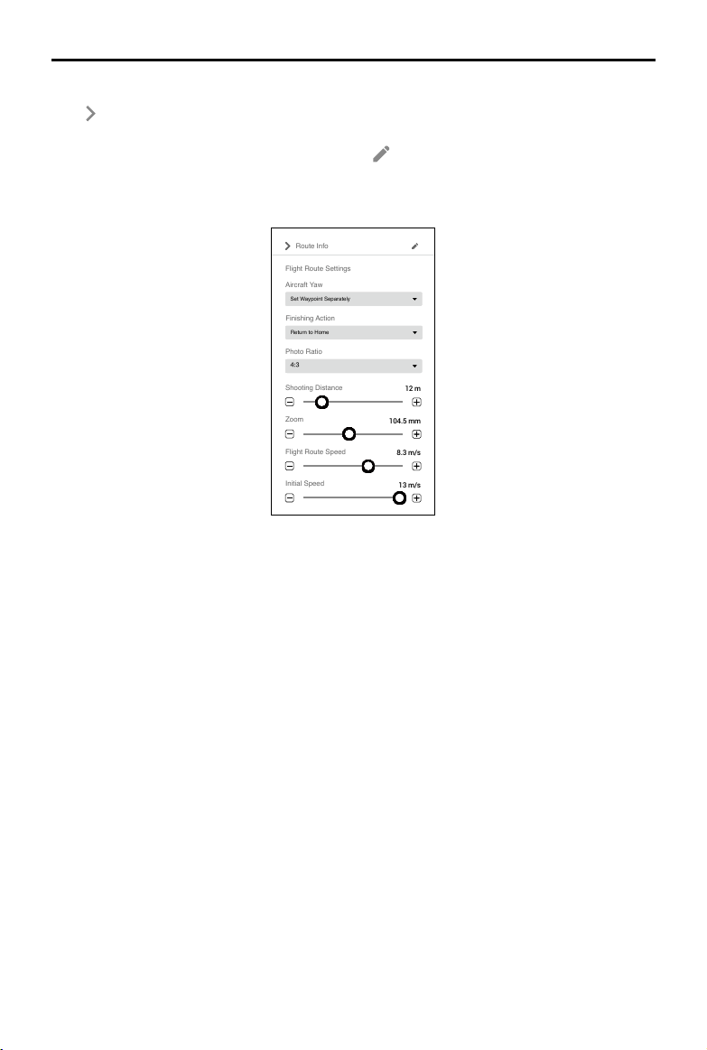
Route Info
Click to collapse the route information. Information based on the current parameter settings will
be displayed, including ight route distance, estimated ight route time, waypoint count, estimated
photo count, aircraft, height mode, and model. Click
to enter the Mission Settings page again to
change the mission name, aircraft and model.
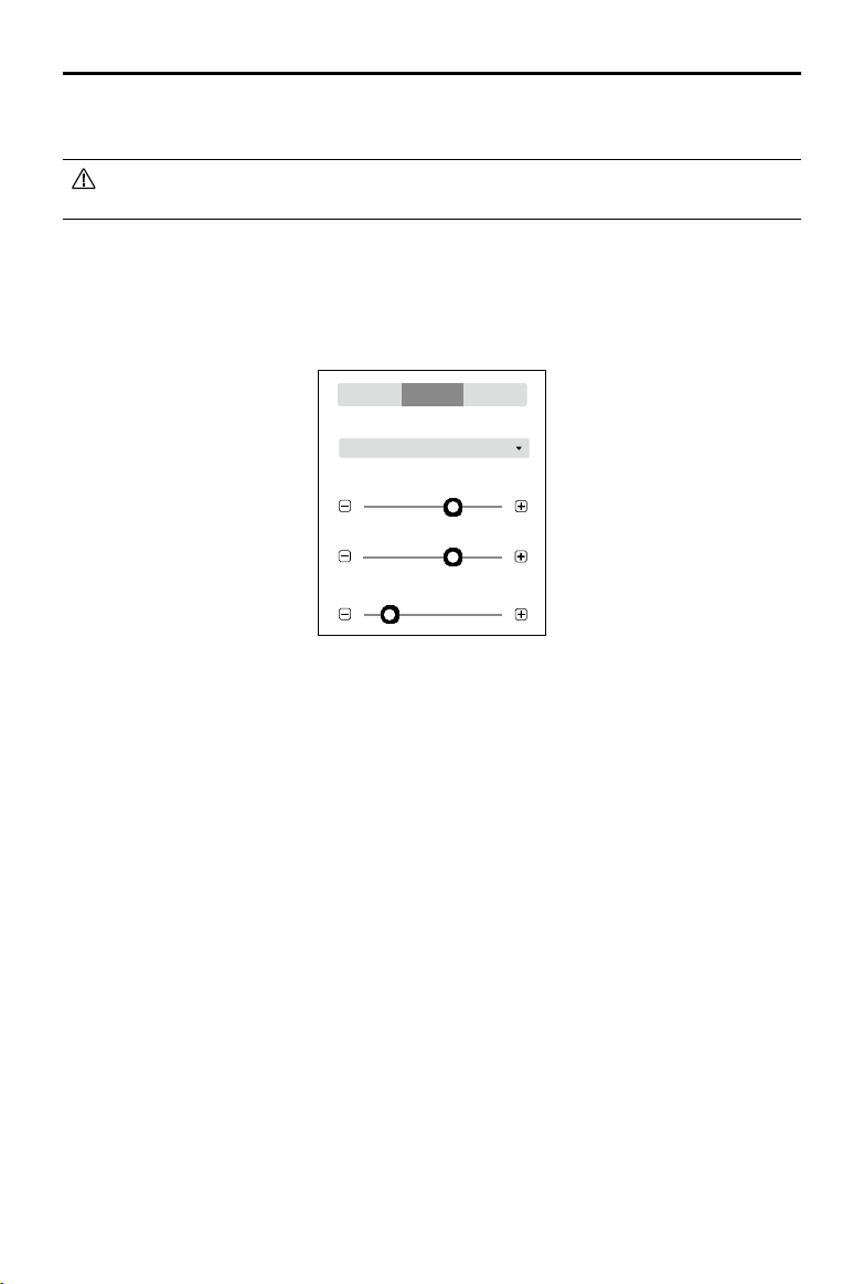
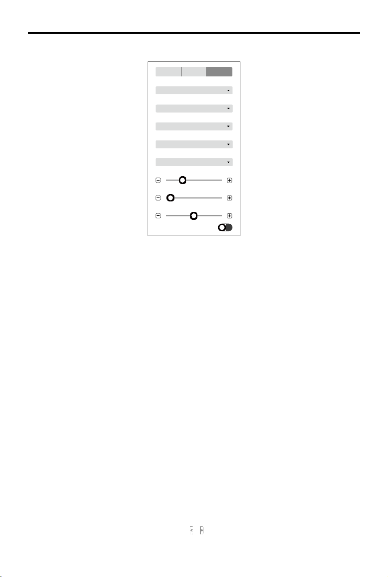
Flight Route Settings
Flight Route Settings
Aircraft Yaw
Set Waypoint Separately
Finishing Action
Return to Home
Route Info
Photo Ratio
4:3
Initial Speed
13 m/s
Flight Route Speed
8.3 m/s
Zoom
104.5 mm
Shooting Distance
12 m
Unless otherwise specied, the ight route settings below will only be applied to the waypoints that
are added after the conguration.
1. Aircraft Yaw
Aircraft yaw when performing the mission.
Set Waypoint Separately: The aircraft yaw will change gradually to the angle pre-set at the next
waypoint if the values at the two consecutive waypoints are different.
Follow Flight Route Direction: The front of the aircraft is always aligned to the direction of the two
consecutive waypoints when ying between the two waypoints.
2. Finishing Action
Aircraft action after mission complete.
Hover: The aircraft will hover at the nal waypoint after mission completion. Then users can then
control the aircraft directly.
Return to Home: If the aircraft altitude is higher than this pre-set value, it will return to home at its
mission completion altitude. If the aircraft altitude is lower than the pre-set value it will ascend to
the RTH altitude after mission completion before returning to home. The RTH altitude can be set
in Flight Controller Settings.
Land: The aircraft will land at the final waypoint and stop motors automatically after mission
completion.
Return and Hover: The aircraft will return to the starting point of the flight path and hover after the
mission is complete. The altitude when returning to the starting point is the same as RTH altitude.
28
©
2021 DJI All Rights Reserved.
DJI TERRA
User Manual
Make sure that the endpoint of the ight path is suitable for landing when nishing action is
set to “Land” to avoid potential ight accidents.
3. Photo Ratio
Set the photo ratio of the photos captured during the mission. 4:3 is the default setting for
Matrice 300 RTK that cannot be changed by users.
4. Shooting Distance
Set the distance between the aircraft and target point when shooting. The range is 1 to 50 m.
5. Zoom
Set the focal length of the camera when shooting. The range is 31.7 to 200 mm. The parameter
will appear only when the aircraft is set to Matrice 300 RTK.
6. Flight Route Speed
The ight speed when ying along a waypoint ight path. The range can be set from 0.2 to 13 m/s.
7. Initial Speed
Flight speed when not ying along the waypoint-determined ight path. This includes the ight
speed from the aircraft position to the starting point of the ight path when starting a mission, or
returning speed after mission completion.
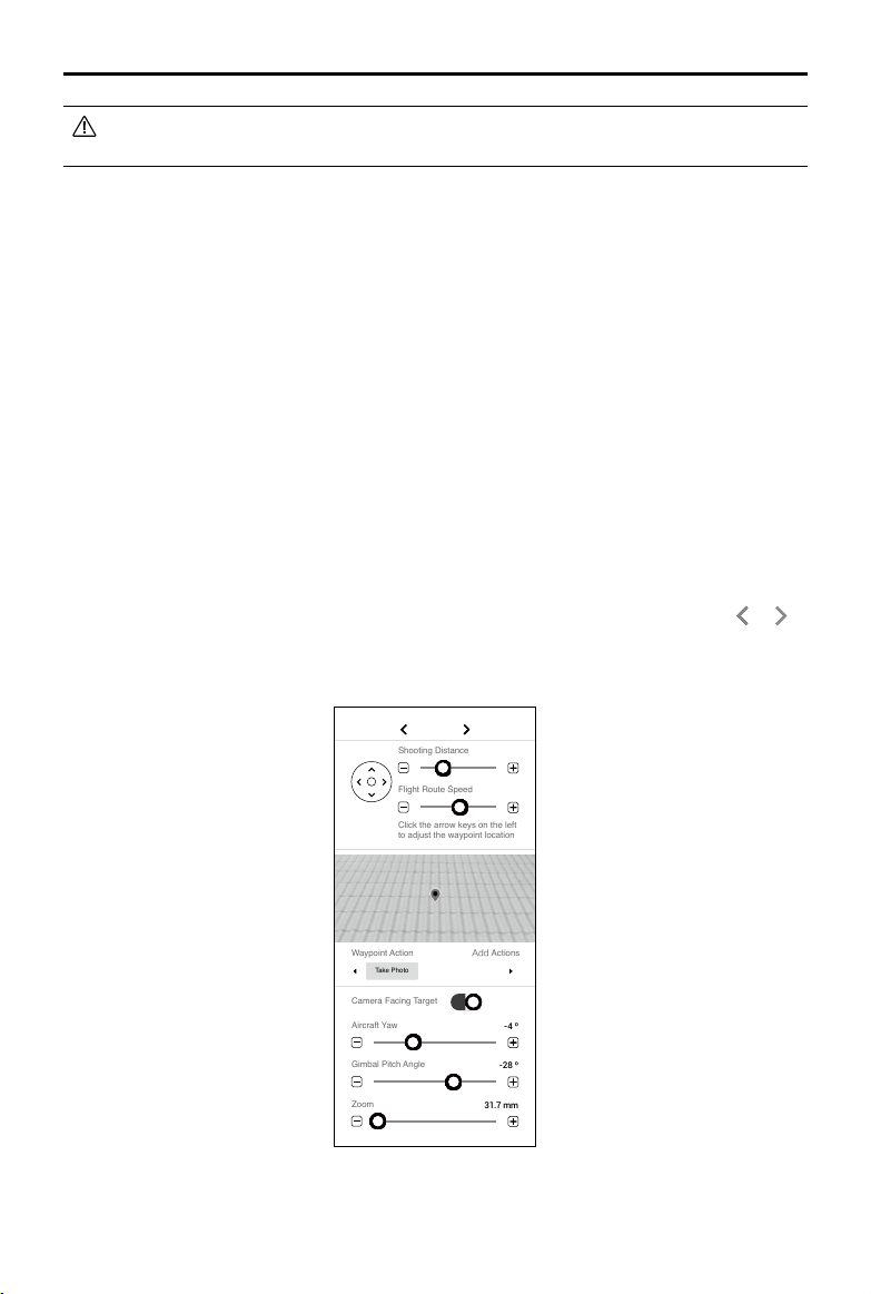
Waypoint Settings
Select a waypoint (it will turn blue when selected) then set waypoint parameters. Click or to
switch to the previous or next waypoint. The keyboard shortcut “Ctrl+ ← ” or “Ctrl+ → ” can also be
used to switch accordingly.
Camera Facing Target
Waypoint Action
Take Photo
Add Actions
Waypoint 04
Zoom
31.7 mm
Gimbal Pitch Angle
-28 º
Aircraft Yaw
-4 º
Flight Route Speed
Click the arrow keys on the left
to adjust the waypoint location
Shooting Distance
3 m
4 m/s

©
2021 DJI All Rights Reserved.
29
DJI TERRA
User Manual
1. Arrow Keys
Click to adjust the waypoint location on upward, downward, left and right directions.
114.20149139404
3
纬titude
22.70718090696
6
经度
纬度
2. Shooting Distance
Set the distance between the aircraft and target point when shooting. The range is 1 to 50 m.
3. Flight Route Speed
The ight speed when ying along a waypoint ight path. The range can be set from 0.2 to 13 m/s.
4. Simulated Camera View
Displays the expected image from the camera’s perspective with the current settings.
5. Waypoint Action
Add actions the aircraft will perform at each waypoint. Name, delete, and order the added actions.
Add Actions: Click the button and then select the desired action.
a. Hover: The aircraft will hover at the waypoint. Set hovering time from 0 to 30 s.
b. Take Photo: Capture on arrival at a waypoint. Users can set the parameters about taking photos
below.
Camera Facing Target — ① When this is enabled, the camera will always face the target point
whatever the other parameter settings are. Users cannot set the aircraft yaw and gimbal pitch
angle. During mission, users can manually adjust the aircraft yaw and gimbal pitch angle at the
waypoint. Note that the operations will change the aircraft position. ② When this is disabled,
users can set the aircraft yaw and gimbal pitch angle here. During mission, if users adjust the
aircraft yaw or gimbal pitch angle at the waypoint, the aircraft position will not change.
Zoom — Set the focal length of the camera when shooting. The range is 31.7 to 200 mm. The
parameter will appear only when the aircraft is set to Matrice 300 RTK.
Name Actions, Delete Actions: Hover the mouse over the added action. Then click
to edit the
name of the action. Click × to delete the action.
Re-Order: Drag the added action to the desired position and release.
30
©
2021 DJI All Rights Reserved.
Reconstruction Missions
Users can use the Reconstruction function with the original photos captured by the aircraft to obtain
a high-precision 2D map or 3D model. After a model has been produced, users have the option to
add annotation and perform a variety of measurements. For photos captured in Mapping and Corridor
missions, both 2D reconstruction and 3D reconstruction are achievable, and agriculture-specic functions
can be done based on a 2D map. For photos captured in Oblique missions, only 3D reconstruction is
available. If the imported photos include a PPK result le from the Cloud PPK Service of the Phantom 4
RTK, this PPK le can be used for 2D or 3D reconstructions at a higher accuracy. If the imported photos
are captured using the P4 Multispectral, you can reconstruct 2D multispectral maps. You can also import
image POS data and generate reconstructions in the designated coordinate system.
Reconstruction mission types also include LiDAR point cloud processing. Use the point cloud data
captured by the Zenmuse L1 to obtain a high-precision true-color point cloud. After the point cloud
has been reconstructed, users can add annotations and perform a variety of measurements.
Importing Image POS Data
After adding the photos, import the image POS data that has already converted to the designated
coordinate system, set the corresponding coordinate system, and generate reconstructions to get
results in the desired coordinate system.
1. Follow the instructions in 2D or 3D reconstruction to import the photos.
2. Import image POS data using one of the two methods:
a. After importing photos captured by a DJI aircraft, click
to export the image POS data,
convert the coordinates and relevant data in a third-party software, and then click
to
import the converted POS data to DJI Terra.
b. Click
to import custom POS data.
3. After the POS data is imported, you will see the page to edit the format and properties. There are
four sections: File Format, Preview, Data Properties, and Dene Data Column.
File Format
Lines to Skip From Top: Select the number of the lines to skip from the top when reading the
data.
Decimal Separator: Select the decimal separator of the data. Choices are: period (.) and comma (,).
Column Separator: Select the separator of the data columns. Choices are: comma (,), period (.),
semicolon (;), space ( ), and tab.
Treat combined separators as one: If the box is checked, the software will treat combined
decimal separators or column separators as one when they exist in the data.
Preview
Preview the content of the imported le. Click
on the upper right corner to add another POS
data le.
Data Properties
POS Data Coordinate System: Select the coordinate system the POS data used and set the
elevation and height offset.
Euler Angles: Set the euler angles of the POS data.
a. N/A: The imported POS data does not include euler angles. Default settings from DJI Terra
will be used.
©
2021 DJI All Rights Reserved.
31
DJI TERRA
User Manual
b. Omega, Phi, Kappa: The imported POS data includes euler angles of Omega, Phi, and
Kappa.
c. Yaw, Pitch, Roll: The imported POS data includes euler angles of Yaw, Pitch, and Roll.
POS Data Accuracy: Set the accuracy of the POS data.
a. Use Default DJI Terra Accuracy: The imported POS data does not include accuracy. Default
settings from DJI Terra will be used. When using images with RTK positioning, the horizontal
accuracy is 0.03 m, and the vertical accuracy is 0.06 m. When using images with non-RTK
positioning, the horizontal and vertical accuracies are 2 m and 10 m respectively.
b. Use Custom Accuracy: Use the horizontal accuracy and vertical accuracy in the POS data
le.
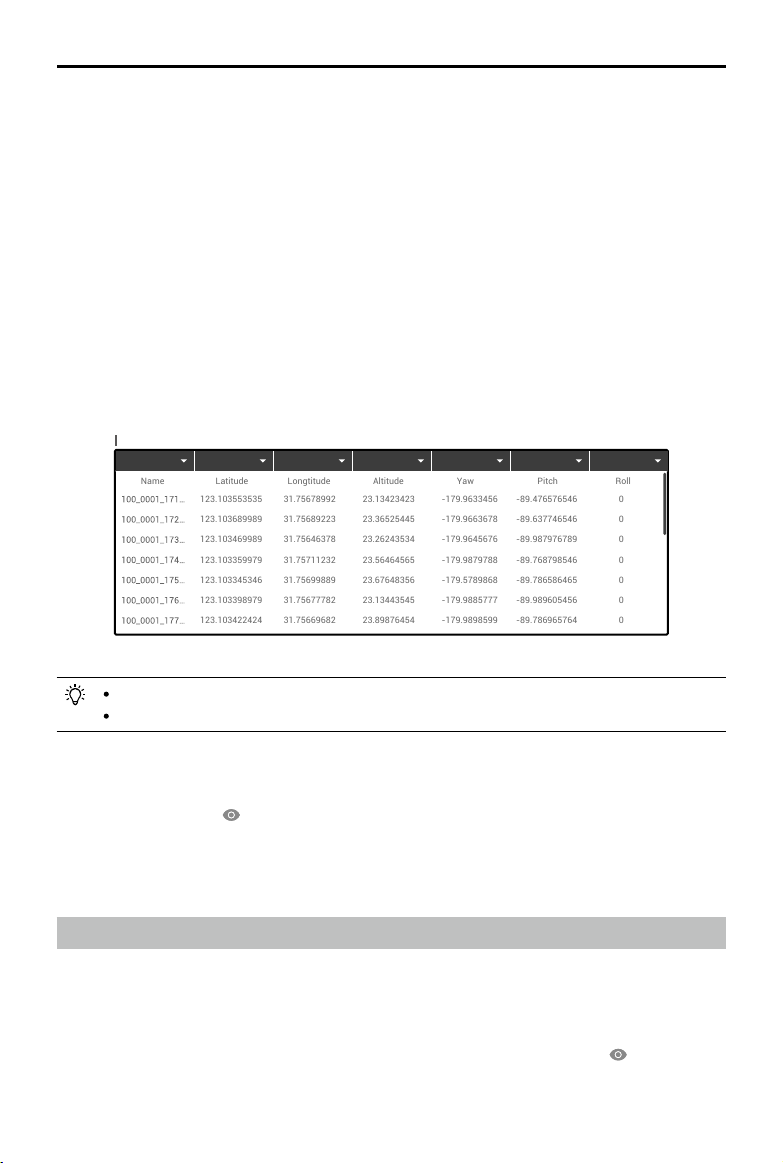
Dene Data Column
Define each column in the POS data file, including photo name, latitude (X/E), longitude (Y/
N), Altitude (Z/U), Omega (Yaw), Phi (Pitch), Kappa (Roll), Horizontal Accuracy, and Vertical
Accuracy.
123.103553535
123.103689989
123.103469989
123.103359979
123.103345346
123.103398979
123.103422424
123.103447722
123.103528574
123.100000009
123.100000009
123.100000009
31.75678992
31.75689223
31.75646378
31.75711232
31.75699889
31.75677782
31.75669682
31.75683357
31.75692240
111.10000008
111.10000008
111.10000008
23.13423423
23.36525445
23.26243534
23.56464565
23.67648356
23.13443545
23.89876454
23.36754364
23.98764533
23.10000008
23.10000008
23.10000008
-179.9633456
-179.9663678
-179.9645676
-179.9879788
-179.5789868
-179.9885777
-179.9898599
-123.1000007
-123.1000007
-123.1000007
-123.1000007
-123.1000007
-89.476576546
-89.637746546
-89.987976789
-89.768798546
-89.786586465
-89.989605456
-89.786965764
-1.1000000009
-1.1000000009
-1.1000000009
-1.1000000009
-1.1000000009
0
0
0
0
0
0
0
-12.10000008
-12.10000008
-12.10000008
-12.10000008
-12.10000008
Define Data Column Total Rows
:
25
Undefined Undefined Undefined Undefined Undefined Undefined Undefined
Name
Longtitude
Latitude
Altitude
Yaw
Pitch
Roll
Photo name, latitude (X/E), longitude (Y/N), and altitude (Z/U) are required.
You cannot select the same denition for multiple columns.
4. After setting the format and properties, click the preview button to view the congured data, and
click the import button after checking the data to import the data for reconstruction.
5. Users can also click
on the right of the Image POS Data section in Reconstruction page to
view the POS data after import. If any setting is incorrect, click the edit button in the preview
page to make changes.
6. Refer to the section below for the remaining instructions on reconstruction.
Using the PPK Result Files
Use PPK result les from the Cloud PPK Service of the Phantom 4 RTK only.
1. Name the result le from Phantom 4 RTK’s Cloud PPK Service as “result.csv”, and store it in the
same folder as the photos you want to import.
2. Follow the instructions in 2D or 3D reconstruction to import the photos.
3. The POS data in the PPK result le will also be imported with the photos. Click
on the right of
Image POS Data to view and edit the POS data in the PPK result le.
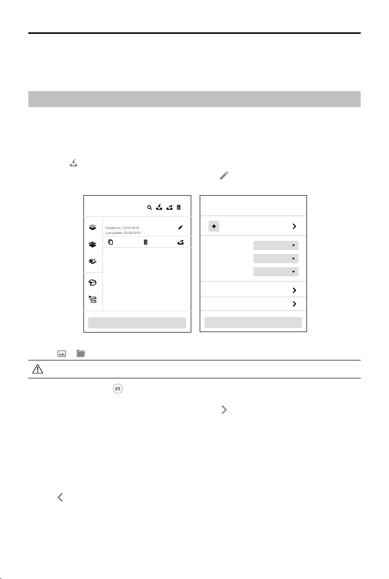
32
©
2021 DJI All Rights Reserved.
DJI TERRA
User Manual
Urban
2D Map
Medium
New 2D Map Mission
Type
Mapping Scenes
Resolution
Annotation and Measurement
Agricultural Application
Add Photo
Start Reconstruction
Mission Library
New Waypoint Mission
Created on: 12/03/2019
Last update: 23/06/2019
New Mission
4. If users want to use the GPS positioning information included in the photos for reconstruction,
remove the PPK result le in the photo folder before importing photos.
5. Refer to the section below for the remaining instructions on reconstruction.
2D Map Reconstruction
Reconstruction Procedure
1. Create a mission via the following two methods:
a. Click the “New Mission” button on the lower left corner, choose the mission type, input the
mission name, and then click “OK” to enter Mission Editing mode.
b. Click
in the right section of the mission library to import a mission le from the computer.
Click to select the imported mission and then click
to enter Mission Editing mode.
2. Click
or . Select photos corresponding to the Mapping mission to add photos.
It is recommended to select at least six photos on two main paths for reconstruction.
3. After import, the icon
will appear on the upper right corner of the map view. Click to turn it
blue indicating that capture location display is enabled. The corresponding location of the photos
captured will be displayed on the map as a dot. Click
on the right to manage the photos. The
photos are grouped by the folders they are located. Expand the list to view and manage photos.
If capture location display is enabled, click the name of the photo to turn it blue and the
corresponding dot on the map will turn orange. Similarly, when you click the dot on the map, its
corresponding photo name in the list will turn blue.
Double-click a photo to view in a large size and zoom in or out.
Click “Manage,” select photos and then click “Delete” to delete photos. Click “Cancel” to exit
management.
Click
to return to the reconstruction page.
4. Select “2D Map” as the reconstruction type.
©
2021 DJI All Rights Reserved.
33
DJI TERRA
User Manual
5. Select the desired mapping scene. Field is suitable for open areas with objects of small height
difference such as farmland, Urban is suitable for areas with more buildings, and Fruit Tree is
suitable for areas with objects of large height difference such as orchard.
DJI Terra will recognize in the reconstruction result to mark different areas such as fruit trees,
buildings, and ground. After reconstruction, in Agriculture Application page, users can add
boundary points of a ight area and calibration point(s) and DJI Terra can automatically generate
a flight path according to the recognition results. For more information, refer to “Agricultural
Application” on p. 36.
6. Select the desired resolution. High refers to the original resolution, Medium refers to 1/2 of the
original resolution (i.e. the length and width are both 1/2 of the original photo), and Low refers
to 1/3 of the original resolution (i.e. the length and width are both 1/3 of the original photo). For
example, if the original photo resolution is 6000x6000, the high resolution is the same, while the
medium resolution is 3000x3000, and the low resolution is 2000x2000.
7. Set the ROI, output coordinate system and manage GCPs if required. Refer to the section below
for details.
8. Click “Start Reconstruction,” a pop-up window will appear to ask if a user wants to copy the
photos to the mission folder. If a user chooses to save a copy, the added photos will be copied
to the current mission folder and they will be included in the mission file when exporting a
mission. If the user does not save a copy, the added photos will not be copied and will not be
included when exporting a mission. Then click “Continue” to start reconstruction. The progress
bar at the bottom will show the mapping progress. Click “Stop” to stop mapping, and the
progress will be saved.
9. Multiple reconstruction missions can be started. Before the rst mission nishes, other missions
will be lined up and processed in order.
10. After mapping, the result will be shown in the map view. Zoom in or out to view the map at different
levels. Annotation and measurement and agriculture applications are also available.
11. Click “Quality Report” to view and save a report in html format. The report includes reconstruction
result overview, RTK status, camera calibration information and process information. Refer to the
document How to Read a DJI Terra Quality Report on the ofcial DJI website for details.
File Format and Storage Path of 2D Maps
The 2D map reconstruction result is raster data in GeoTIFF format which can be used in third party
software compatible with GeoTIFF format.
The default storage path of the 2D map les is as below. This cache directory can be changed in
Settings.
C:\Users\<computer name>\Documents\DJI\DJI Terra\<DJI account name>\<mission code>\map\result.tif
In the reconstruction page, users can open the current mission folder using the keyboard shortcut
“Ctrl+Alt+F”.
If PC GS Pro has been used on your computer, after DJI Terra has been installed, the
cache directory will still be as follows:
C:\Users\<computer name>\Documents\DJI\Groundstation\Missions\<DJI account name>
The mission code is the number generated by the software automatically when a mission
is created. It cannot be changed by users.
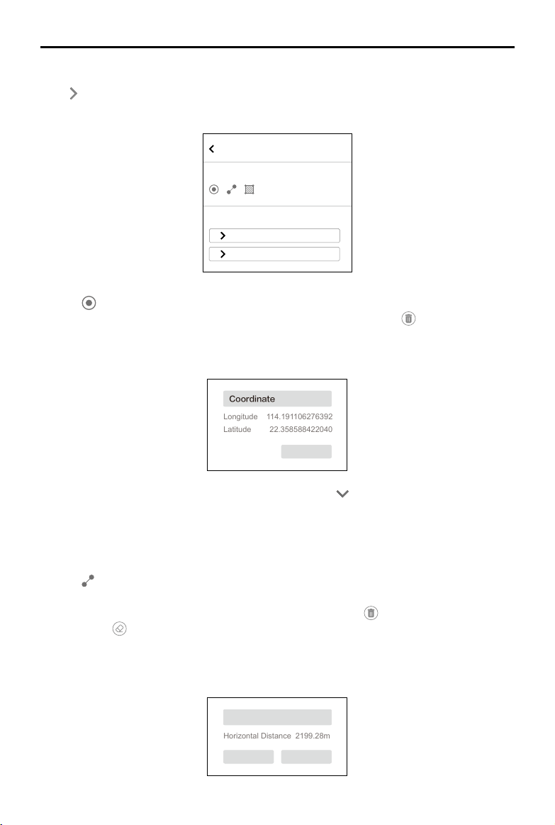
34
©
2021 DJI All Rights Reserved.
DJI TERRA
User Manual
Annotation and Measurement
Measurement
Coordinate Manage
Measurement 1
Measurement 2
Coordinate
1. Click
to enter Coordinate Adding mode.
2. Click on the map to add a coordinate. Drag to adjust its position. Click
on top to delete the
coordinate. The box below the coordinate shows the name, longitude, and latitude, indicating
that the coordinate is in editing status. Click the text box of the name to input the name, then
click “Save” to exit editing.
22.358588422040
Horizontal Distance
Area
2199.28m
Coordinate
Longitude 114.191106276392
Latitude
Distance
Area
5667.84m
2
SaveCancel
Save
Save
3. The coordinate list displays the added coordinates. Click to expand the information to view
the longitude and latitude and change the name.
4. Make sure that there is no coordinate in editing status. Click “Manage,” and select coordinates
(the outer box of the coordinate will turn blue when selected) to export or delete them.
Distance
1. Click
to enter distance measurement mode.
2. Click the left mouse button on the map to add measurement points. Drag to adjust the position.
The selected point is red, while the unselected point is gray. Click
on top to delete the selected
point. Click
to delete all the points in this measurement. Click the right mouse button to end
measurement. The box below the line shows the name and horizontal distance. Click the text
box of the name to input the name, then click “Save” to exit editing. A distance measurement is
in editing status when the measurement is not ended or saved. To exit editing status, end the
measurement and save.
Annotation and Measurement
Click on the right of Annotation and Measurement bar to enter the page. Users can add
coordinates, measure distance and area.
22.358588422040
Horizontal Distance
Area
2199.28m
Coordinate
Longitude 114.191106276392
Latitude
Distance
Area
5667.84m
2
SaveCancel
Save
Save
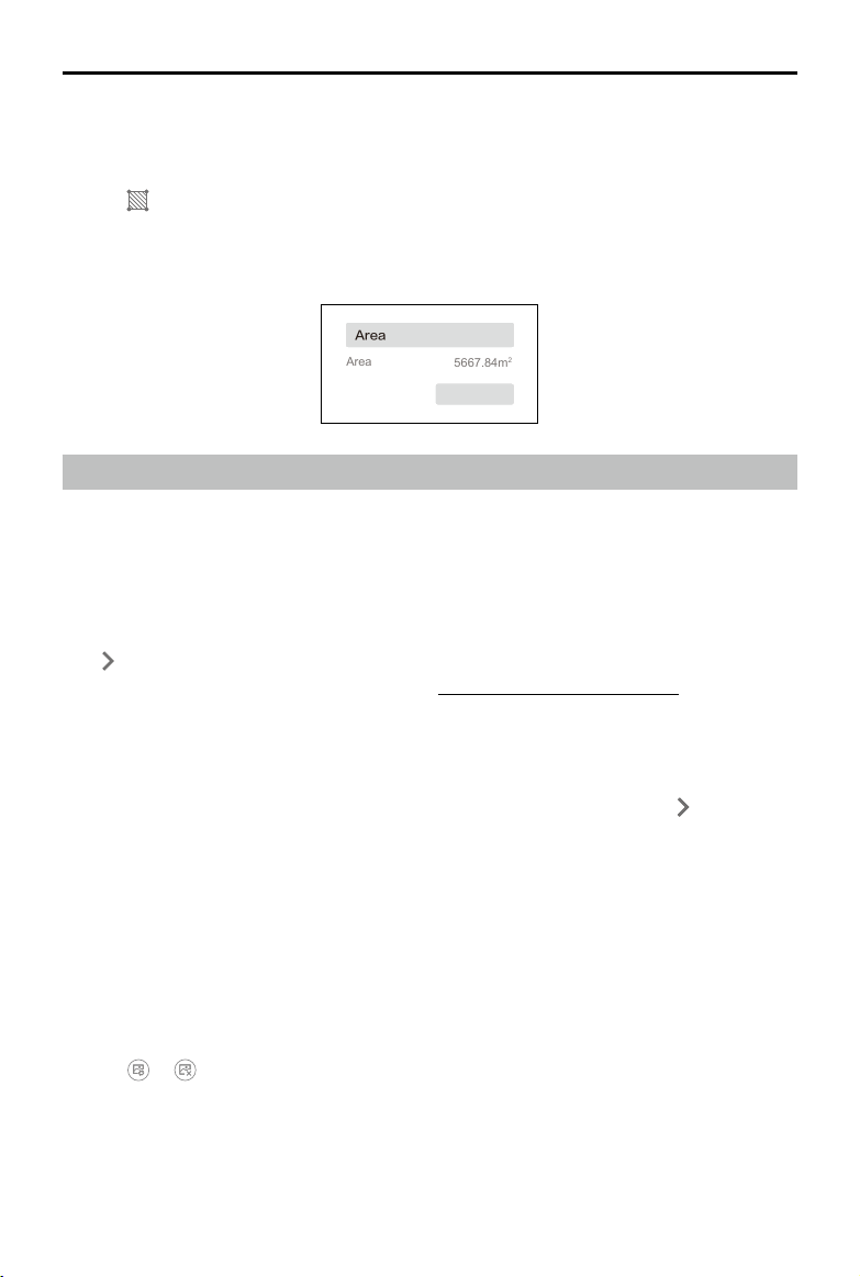
©
2021 DJI All Rights Reserved.
35
DJI TERRA
User Manual
3. The process to view and manage distance measurements is the same as the one used for
coordinates.
Area
1. Click
to enter area measurement mode.
2. As with distance measurement, the procedure to add measurement points for area is similar.
The only difference is that there are three measurements points required before ending the
measurement, which is achievable by clicking the right mouse button.
22.358588422040
Horizontal Distance
Area
2199.28m
Coordinate
Longitude 114.191106276392
Latitude
Distance
Area
5667.84m
2
SaveCancel
Save
Save
2D Multispectral Map Reconstruction
2D multispectral map reconstruction is only supported when using photos captured by the P4
Multispectral. The reconstruction procedure is similar to that of 2D map reconstruction. Users
can view the supported vegetation index outputs. Radiometric correction is available before
reconstruction to improve the reliability of the output index when images of the calibration board
and the camera reectance factor can be obtained.
Annotations and measurements can be done the same way you would after a 2D map reconstruction.
Click
on the right of Agricultural Application bar to enter the page. Users can plan operations on the
2D multispectral map. For more information, refer to "Agricultural Application" on p. 36.
Radiometric Correction
Radiometric correction can reduce the effects on images caused by weather and time and helps to
output more reliable indexes in reconstruction missions. Multispectral images with radiometric correction
can be reconstructed to a 2D multispectral map with an output of reectance. Click
on the right of
Radiometric Correction bar to enter the page. After conguration, return to the reconstruction page to
start reconstruction with radiometric correction.
Importing Calibration Board Data
Users should import at least one group of images of the calibration board in each band and up to
three groups. The groups are named Calibration Board 1, 2, and 3.
1. Select Calibration Board 1, 2, or 3.
2. Click Import Calibration Photo and select photos including the calibration board in blue, green,
red, red edge, and near infrared bands to import.
3. Click the photo in the desired band and the photo will be displayed on the main screen on the left.
4. Click
or to replace or delete the selected photo.
5. Input the corresponding reectance factor in the text box for each band.
36
©
2021 DJI All Rights Reserved.
DJI TERRA
User Manual
Marking the Calibration Board
1. Click the photo displayed on the main screen on the left to add a point as a mark of the edge of
the calibration board in the photo.
2. Drag the edge point to adjust the position.
3. Click
to delete all the points in the selected photo.
4. Mark the calibration board for each photo accordingly.
5. The marks of the calibration board will be applied to the next group of images of the calibration
board. Drag the edge points to adjust if needed.
Vegetation Index Outputs
DJI Terra supports 5 types of vegetation indices: NDVI, LCI, GNDVI, OSAVI, and NDRE, each
requiring photos from different spectral bands. DJI Terra will display the indices that can be
calculated according to the imported photos. There will be notications under output index if any
photos are missing in the required band. After reconstruction, click the buttons for different indices
to view the results.
Even if only one photo is missing from a required band for the desired vegetation index, it is
considered that the information of that whole band is missing. Users can view which photos
are missing in the required band in the photo list.
File Format and Storage Path of 2D Multispectral Maps
The 2D multispectral map reconstruction results are raster data in the GeoTIFF format which can be
used in third party software compatible with GeoTIFF format. The results include multispectral index
maps for each index, 2D orthographic maps in RGB and for each of the spectral bands. The default
storage path of the 2D multispectral map files can be found below. In the reconstruction page,
users can open the current mission folder using the keyboard shortcut “Ctrl+Alt+F”. This cache
directory can be changed in Settings.
The default storage path of the multispectral index maps is
C:\Users\<computer name>\Documents\DJI\DJI Terra\<DJI account name>\<mission code>\map\
index_map
The default storage path of the 2D orthographic maps in RGB and for each of the spectral bands is
C:\Users\<computer name>\Documents\DJI\DJI Terra\<DJI account name>\<mission code>\map
The result.tif le is the RGB 2D orthographic map. The result_XXX.tif le is the 2D orthographic map
for the spectral band corresponding to “XXX” in the le name.
Agricultural Application
For 2D map reconstruction (Field and Fruit Tree) and 2D multispectral map reconstruction, click on
the right of the Agricultural Application bar to enter the page. Users can plan operations for elds or
fruit trees on the map.
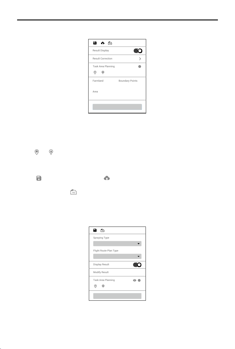
©
2021 DJI All Rights Reserved.
37
DJI TERRA
User Manual
Generate 3D Flight Route
Display Result
Modify Result
Flight Route Plan Type
Distance Interval (Auto)
Spraying Type
Continuous Spraying
Task Area Planning
Field
Generate Route
Result Display
Result Correction
1
221597.72
6
Farmland
Area
Boundary Points
Generate Route
Task Area Planning
1. If Display Result is enabled, recognition for different areas such as fruit trees, buildings, ground,
water, and poles will be displayed on the map.
2. Click Modify Result to use the corresponding brush for each type of area to paint on the map to
modify the recognition result.
3. Click
and to add boundary points and calibration points in the area that includes elds.
4. Click “Generate Route.” DJI Terra will automatically generate a route for eld operations. Users
can enable or disable route display and obstacle avoidance, and congure altitude, route width,
and route angle.
5. Click
to save the mission. Click and the mission will be uploaded to DJI Agras
Management Platform. Agras aircraft users can download the mission from the platform to the
compatible app. Click
and the mission will be exported to the microSD card in the remote
controller connected to the computer. Insert the card into the Agras remote controller and import
the mission in the pop-up menu in the app.
Fruit Tree
38
©
2021 DJI All Rights Reserved.
DJI TERRA
User Manual
1. Select Spraying Type. When using an Agras aircraft to perform the ight mission generated by
DJI Terra, the aircraft will spray according to the selected type.
Continuous Spraying refers to spraying when ying within a recognized fruit tree area and is
suitable for orchards with moderately sized and evenly distributed fruit trees.
Spot Spraying refers to spraying only when ying to the center of the tree crown in the recognized
fruit tree area and is suitable for orchards that have scattered trees with thick crowns.
2. Select Flight Route Plan Type. The plan type varies for different spraying type. Continuous
spraying corresponds to Distance Interval (Auto), Tree Crown Center (Auto), Semi-automated,
and Manual, while Spot spraying corresponds to Tree Crown Center (Auto) and Semi-automated.
Six planning methods are available for different operation scenarios when combining the parameters
above: Continuous Spraying - Distance Interval (Auto), Continuous Spraying - Tree Crown Center
(Auto), Continuous Spraying - Semi-automated, Continuous Spraying - Manual, Spot Spraying - Tree
Crown Center (Auto), and Spot Spraying - Semi-automated. Refer to the descriptions below.
3. If Display Result is enabled, recognition for different areas such as fruit trees, buildings, ground,
water, and poles will be displayed on the map.
4. Click Modify Result to modify the recognition result manually. Operation varies for different
spraying types:.
• When Continuous Spraying is selected, use the corresponding brush for each type of area to
paint on the map to modify the recognition result.
• When Spot Spraying is selected, circles will be displayed on the map to mark the tree crown
centers. Click
to edit them. Click the recognized tree crown center to select it, then click
to delete. Click on the map to mark a new tree crown center.
5. Click
and to add farmland points and calibration points in the area that includes fruit trees.
Click the icon
or to show or hide the planned farmland and calibration points. The farmland
points that can be added vary for different ight route plan type, such as boundary points and
waypoints. Refer to the description below.
6. Click “Generate 3D Flight Route.” DJI Terra will automatically generate a route for fruit tree
operations. Users can enable or disable route display and obstacle avoidance, and congure
route altitude, route width, route angle and terrain follow accuracy.
7. Click
to save the mission. Click and the mission will be exported to the microSD card in
the remote controller connected to the computer. Insert the card into the Agras remote controller
and import the mission in the pup-up menu in the app.
Continuous Spraying - Distance Interval (Auto)
After adding boundary points and calibration points, click “Generate 3D Flight Route.” DJI Terra will
automatically generate a zig-zag route with a same line spacing in the eld. This function ts the
needs of most large orchards.
Continuous Spraying - Tree Crown Center (Auto)
After adding boundary points and calibration points, click “Generate 3D Flight Route.” DJI Terra will
automatically generate a route including all the tree crown centers. This is suitable for orchards with
evenly distributed trees and where continuous spraying is required.
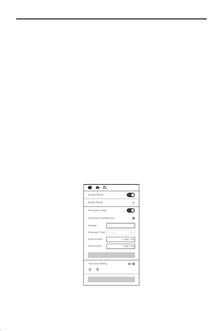
©
2021 DJI All Rights Reserved.
39
DJI TERRA
User Manual
Continuous Spraying - Semi-automated
Click on the map to add waypoints along the fruit trees. The ight route will contain the waypoints.
Click “2D Flight Route Preview.” DJI Terra will adjust the waypoints according to the location of
the tree crown centers. Click “Back” after the preview, then click “Generate 3D Flight Route” to
generate the nal ight route. This is suitable for orchards with trees distribution following some kind
of pattern and where continuous spraying is required.
Continuous Spraying - Manual
Click on the map to add waypoints along the fruit trees. The ight route will contain the waypoints.
Click “Generate 3D Flight Route.” DJI Terra will automatically generate a route. This is suitable for
orchards with unevenly distributed trees and where a custom ight route is required.
Spot Spraying - Tree Crown Center (Auto)
After adding boundary points and calibration points, click “Generate 3D Flight Route.” DJI Terra will
automatically generate a route including all the tree crown centers. This is suitable for orchards with
evenly distributed trees and where only spraying on the top of the trees is required.
Spot Spraying - Semi-automated
Click on the map to add waypoints along the fruit trees. The ight route will contain the waypoints.
Click “2D Flight Route Preview.” DJI Terra will generate a route that connects all the tree crown
centers within 1.5 m of the waypoints. Click “Back” after the preview, then click “Generate 3D Flight
Route” to generate the nal ight route. This is suitable for orchards with a tree distribution following
some kind of pattern and where only spraying on the top of the trees is required.
2D Multispectral Map
Prescription Map
Task Area Editing
Modify Result
4.00
131.87
3.00
5.00
L (kg) / Ha
L (kg) / Ha
L (kg) / Ha
L (kg)
Display Result
Parameter Configuration
Average
Estimated Total
Good Growth
Poor Growth
Apply
Generate Route
40
©
2021 DJI All Rights Reserved.
DJI TERRA
User Manual
1. If Display Result is enabled, recognition for different areas such as fruit trees, buildings, ground,
water, and poles will be displayed on the map.
2. Click Modify Result to use the corresponding brush for each type of area to paint on the map to
modify the recognition result.
3. Click
and to add boundary points and calibration points in the area that includes elds.
4. Select a planned field and set the material amount for average, good, and poor growth in
Parameter Conguration. Click
to view the detailed descriptions for the parameters.
5. Click Apply and wait for the software to generate the prescription map. Users can select to show
or hide the prescription map.
The prescription map is used for Agras aircraft to conduct variable rate fertilizer application. Users
can adjust the parameters to change the prescription map. When a prescription map is shown in
NDVI view, each eld on the map will be displayed in a color corresponding to its material amount
according to the color bar on the left. Hover the mouse on the map to view the specic amount.
6. Click “Generate Flight Route.” DJI Terra will automatically generate a route for eld operations.
Users can enable or disable obstacle avoidance and congure route altitude, route width, and
route angle.
7. Click
to save the mission. Click and the mission will be uploaded to DJI Agras
Management Platform. Agras aircraft users can download the mission from the platform to a
compatible app. Click
and the mission will be exported to the microSD card in the remote
controller connected to the computer. Insert the card into the Agras remote controller and import
the mission in the prompted menu in the app.
3D Model Reconstruction
Reconstruction Procedure
1. The method to enter the reconstruction page and add photos is similar to that used for 2D
reconstruction.
3D reconstruction occupies more computer resources. To ensure smooth 3D reconstruction
processes by adding an adequate amount of photos, refer to the number of photos corresponding
to the following computer congurations.
Graphic Card RAM Max Photo Amount Photo Resolution
GeForce GTX 1050Ti with
a VRAM of 4GB
16GB 1600
4864x3648
32GB 3200
48GB 4800
64GB 6400
128GB 12800
2. Set the reconstruction type to “3D Model”.
3. Select the desired resolution. High refers to the original resolution, Medium refers to 1/2 of the
original resolution (i.e. the length and width are both 1/2 of the original photo), and Low refers
to 1/3 of the original resolution (i.e. the length and width are both 1/4 of the original photo). For
example, if the original photo resolution is 6000x6000, the high resolution is the same, while the
medium resolution is 3000x3000, and the low resolution is 1500x1500.

©
2021 DJI All Rights Reserved.
41
DJI TERRA
User Manual
4. Select mapping scenarios. Normal works for most scenarios, including oblique and nadir view.
Circle is suitable for scenarios where images are captured by ying around vertical structures or
assets such as a communications towers, power towers, or wind turbines. Electricity is suitable
for scenarios with power lines.
5. Enable or disable the options below to select the desired reconstruction results.
Aerotriangulation option: This option is enabled by default to generate the aerotriangulation
measurement result, and cannot be disabled. The format will be a Terra le by default. Users
can change the output to the XML format, i.e., Context Capture Blocks Exchange.
Point Cloud option: If enabled, a 3D point cloud will be generated. The default format for the
point cloud is pnts. Users can set to other formats. LAS refers to the ASPRS LASer format for the
3D point cloud le. S3MB refers to the s3mb format for the SuperMap LOD 3D point cloud le.
PLY or PCD refers to the ply or pcd format for the non-LOD 3D point cloud le respectively.
Model option: If enabled, a 3D model will be generated. The default format for the LOD model
is b3dm. Users can also output into other formats. OSGB refers to the osgb format for the LOD
model. OBJ refers to the obj format for non-LOD models. PLY refers to the ply format for non-
LOD models. S3MB refers to the SuperMap LOD models. I3S refers to the i3s format for LOD
models that can be viewed in the ArcGIS client server or web page.
6. Set the ROI, output coordinate system and manage GCPs if required. Refer to the section below
for details.
7. Click “Start Reconstruction,” a pop-up window will appear to ask if users want to copy the photos
to the mission folder. If a user chooses to save a copy, the added photos will be copied to the
current mission folder and they will be included in the mission le when exporting a mission.
If a user does not save a copy, the added photos will not be copied and will not be included
when exporting a mission. Then click “Continue” to start reconstruction. The progress bar at the
bottom will show the mapping progress. Click “Stop” to stop modeling, and the progress will be
saved. If a user selects to continue after stopping a modeling session, DJI Terra will track back
slightly from the saved progress and then continue modeling.
8. Multiple reconstruction missions can be started. Before the rst mission nishes, other missions
will be lined up and processed in order.
9. After modeling, users can translate and rotate the model, and zoom in or out to view it from
different angles.
There will be three icons on the right screen and the model can be viewed at different settings.
: Shows the orthographic projection of the 3D model. In this view, hold down the left mouse
button and drag to translate model.
/ : Displays the 3D model in top view or front view. In any of the two views, hold down the
left mouse button and drag to translate the model, scroll the mouse wheel or hold down the right
mouse button and drag to zoom in or out, and hold down the mouse wheel and drag to rotate.
10. Click “Quality Report” to view and save a report in html format. The report includes an overview
of the reconstruction result, RTK status, camera calibration information and process information.
Refer to the document How to Read a DJI Terra Quality Report on the ofcial DJI website for
details.
42
©
2021 DJI All Rights Reserved.
DJI TERRA
User Manual
File Format and Storage Path of 3D Reconstruction Results
DJI Terra can output aerial triangulation results in the following formats: Terra and XML.
DJI Terra can output 3D point clouds in the following formats:
1. Non-LOD point cloud le in the las, ply, and pcd formats.
2. LOD cloud le in pnts and s3mb formats. Format conversion is not supported.
DJI Terra can output 3D models in the following formats:
1. Texture mesh le in ply and obj formats.
2. LOD model le in b3dm, osgb, i3s, and s3mb formats. Format conversion is not supported.
The default storage path of the 3D reconstruction les is as follows:
C:\Users\<computer name>\Documents\DJI\DJI Terra\<DJI account name>\<mission code>\
models\pc\0
In the reconstruction page, users can open the current mission folder using the keyboard shortcut
“Ctrl+Alt+F”.
NOTE: This cache directory can be changed in Settings.
If PC GS Pro has been used on your computer, after DJI Terra has been installed, the
cache directory will still be as follows:
C:\Users\<computer name>\Documents\DJI\Groundstation\Missions\<DJI account name>
The mission code is the number generated by the software automatically when a mission
is created. It cannot be changed by users.
Annotation and Measurement
Click on the right of Annotation and Measurement bar to enter the page. Users can add coordinates,
measure distance, area and volume based on a specied coordinate system. For example, when
using the photos captured by a Phantom 4 RTK aircraft in WGS84 coordinate system, the altitude
involved in Annotation and Measurement refers to the ellipsoidal height. If using other coordinate
systems, the altitude corresponds to the elevation in the coordinate system that the photos use.
The method to add coordinates, measure distance and area is similar to the one in 2D
reconstruction, but the data included is different. When measuring the volume, it is required to
select the base plane. The following is a description of the data of coordinate, distance, area and
volume in 3D reconstruction.
Coordinate: The three-dimensional coordinate of the added coordinate point, including longitude,
latitude and altitude. The altitude corresponds to the elevation in the coordinate system that the
photos use.
Distance: The horizontal distance is the length of the horizontal projection of the line segment
between the two added measurement points, the vertical distance is the height difference between
the two points, and the straight distance refers to the spatial distance between the two points, i.e.,
the length of the line segment between two points. If a polyline is added, the straight distance is the
sum of the straight distances for each segment.
Area: Refers to the projected area of the polygon area formed by the added measurement points
along the elevation direction.

©
2021 DJI All Rights Reserved.
43
DJI TERRA
User Manual
Volume: When projecting the polygon area formed by the added measurement points along
the elevation direction, a polyhedron is produced. With reference to the specified base plane,
the volume refers to the cut and ll volume of the model. The portion above the base plane (the
direction in which the elevation is increased) is the cut, and the portion below the base plane (the
direction in which the elevation is reduced) is the ll. There are two options for the base plane, the
Mean Plane and the Lowest Point.
• Mean Plane: A plane (possibly an inclined plane) tted with multiple measurement points as the
reference plane.
• Lowest Point: Use the plane of the lowest elevation point among the measurement points as the base
plane.
The Annotation and Measurement of the 3D model also includes the function to display the camera
pose when adding coordinates.
1. Enable “Camera Pose” and the green patterns indicates the camera pose when the photo was
captured.
2. Click
to enter Coordinate Adding mode.
3. Click on the model to select a point. The camera pose display of the photos including the
selected point will turn yellow, and a photo preview from the camera's perspective will be
displayed at the bottom of the screen.
4. The yellow cross in the preview photo indicates the position of the point on the model in the
photo. Click the photo, and the corresponding camera pose display will turn blue. Double-click
the photo to view in a large size and zoom in or out.
ROI Reconstruction
During 2D or 3D reconstruction, users can select a region of interest (ROI) for reconstruction after
adding photos, which will save the time of reconstruction and improve efciency. Click
on the
right of the ROI Reconstruction bar to enter the page and dene the ROI. Follow the instructions
below. After configuration, return to the reconstruction page to start reconstruction, then the
reconstruction will be carried out in the dened ROI.
44
©
2021 DJI All Rights Reserved.
DJI TERRA
User Manual
Aerial Triangulation
Aerial triangulation should be performed before dening the ROI.
1. Click “Aerotriangulation” on the lower right corner to start aerial triangulation and wait until it’s
completed.
2. Click “Aerotriangulation Report” to view the report and make sure that the data is correct.
Dene ROI
There are four methods to dene the ROI for reconstruction. The coordinate system used here is the
same as the one in Output Coordinate System settings.
1. Click “KML Import” to convert the points in the KML le into the edge points of the ROI.
2. Input the min and max latitude, longitude, and height or XYZ values of the ROI in the text boxes,
and then click “Apply” to dene the ROI.
3. In the “Reset Region” option, click “Auto” or “Max Region”, and DJI Terra will generate the
corresponding ROI automatically.
Auto: DJI Terra will calculate a proper cuboid region automatically according to the point cloud
distribution.
Max Region: The cuboid region covering the whole point cloud.
4. Click
on the top of the screen to enter editing mode. Click on the map to add the edge points
of the ROI, and then input the height in the height text box to dene the ROI.
Translate ROI
Click to enter translation mode, and then drag the dened ROI to translate it.
Edit ROI
Click to enter editing mode.
1. Click on the map to add edge points of the ROI.
2. Drag the edge point to adjust its location and the shape of the ROI.
3. Select the edge point, and then click
to delete it.
4. Click
to delete all the edge points.
5. Click
to exit from editing mode.
Other Information and Settings
1. When the ROI is a cuboid, its length, width, and height will appear on the top of the page.
2. Show Camera Pose: Show or hide the camera pose of the added photos.
3. Display Region: Show or hide the dened ROI.
Output Coordinate System Settings
When generating 2D or 3D reconstructions, users can set the output coordinate system after
importing images. The coordinates in the reconstruction result will be converted to the designated
coordinate system.
Click
on the right of Output Coordinate System Settings bar to enter the settings page. If the
images imported do not include GPS information, the output coordinate system will be automatically
set to “Any Coordinate System” dened by DJI Terra. If the images include GPS information, the
output coordinate system will be automatically set to “Known Coordinate System” and converted to
©
2021 DJI All Rights Reserved.
45
DJI TERRA
User Manual
Marking View
Photo
Gallery
Aerial Triangulation View
GCP List
GCP Information
a projected coordinate system in WGS 84. Users can select other known coordinate systems and
set the altitude. Follow the instructions below.
1. Known Coordinate System Settings
There are two methods to set the known coordinate system, importing a PRJ le and searching
in DJI Terra.
Importing a PRJ le: Search and download the .prj le for the desired coordinate system on the
website https://spatialreference.org. Then click “Import PRJ” in DJI Terra to import.
Searching in DJI Terra: Click “Search”, input the coordinate system name or authorization code,
select the desired coordinate system in the searching results. Then click “Apply”.
2. Altitude Settings
DJI Terra supports Default (ellipsoid height), EGM96, EGM2008, NAVD88, NAVD88 (ftUS),
NAVD88 (ft), JGD2011 (vertical).
GCP Management
Ground Control Points (GCPs) are marked points on the ground with known coordinates
and are clearly visible in an image. GCPs can be obtained using photogrammetry
methods such as GPS-RTK or a total station. GCPs are used to optimize the result of aerial
triangulation. There are also check points that are used to check for the absolute accuracy
of aerial triangulation.
When generating 2D or 3D reconstructions, users can import GCPs after importing images to help
increase the robustness and accuracy of aerial triangulation, check the accuracy of the aerial
triangulation against actual measurements, and convert the aerial triangulation result into the one in
the GCP’s coordinate system. Note that the positioning and pose of the camera should be included
in the added images or be imported after images added.
Click
on the right of GCP Management bar to enter the page. The page includes GCP list,
GCP information, photo gallery, aerial triangulation view, and marking view. The marking view will
appear on the left of the aerial triangulation view after an image is selected in the photo gallery, as
shown below. Users can add GCPs, mark points, and conduct aerial triangulation calculation and
optimization.
46
©
2021 DJI All Rights Reserved.
DJI TERRA
User Manual
Aerial Triangulation
In the GCP management page, DJI Terra will process the added images, and the camera
positioning and attitude information will be shown on the map when complete. Click
“Aerotriangulation” at the bottom of the screen to start aerial triangulation calculation. The result
will be shown on the screen when complete, including camera positioning and attitude and aerial
triangulation points.
GCP Coordinate System
Click on the left of GCP Coordinate System bar to set the GCP coordinate system by following the
same instructions as the ones for output coordinate system conguration.
Optimization
Import a GCP le and mark points on the images to optimize the aerial triangulation.
Importing GCP Files
1. Preparing GCP Files
The GCP data in the le should be in this order: point name, latitude/X/E, longitude/Y/N, height/Z/
U, horizontal accuracy, vertical accuracy. Accuracy data is optional. Each column is separated
with a space or a tab. The example is as shown below. Note that in the projected coordinate
system, X represents the East, and Y represents the North.
Name Latitude Longitude Height
1 22.0 113.0 1.0
2 22.5 113.5 2.0
a 23.0 114.0 3.0
b 23.5 114.5 4.0
2. Importing GCPs
Click
, and select the desired GCP le to import it. Users can also import GCPs with marked
points by clicking
. After importing, the GCPs will be shown in both the aerial triangulation
view and GCP list.
You can only import GCP les in the json format that are exported in DJI Terra when using
to import GCPs.
3. Editing GCPs
Click to select a GCP. It will turn blue in the aerial triangulation view and GCP list when selected.
The camera position of the images that contain the selected GCP will turn yellow. The blue cross
on the thumbnail in the photo gallery represents the GCP’s projected result on the image. When
“Only display photos with GCP” is enabled, only the images on which the current GCP can be
projected and images including marking points will be displayed.
Press and hold the Ctrl key on the keyboard and click the GCPs to select multiple GCPs. Click
to delete the selected GCPs.
©
2021 DJI All Rights Reserved.
47
DJI TERRA
User Manual
Click to add a GCP. Set the GCP as a control point or a check point , and input its
horizontal accuracy, vertical accuracy, and coordinates in the coordinate system the GCPs are in.
Marking
1. Select a GCP, and click one of the images including the selected GCP in the photo gallery. The
marking view will display on the left of the aerial triangulation view. The blue cross in the marking
view represents the GCP’s projected result on the image.
2. In the marking view, hold the left button on the mouse to drag the image, scroll to zoom in and
out. Click on the image using the yellow cross to mark the GCP’s actual location in the image.
The marked point is displayed in the marking view and photo gallery with a green cross, and
there will be a check mark on the upper right corner of the image in the photo gallery, indicating
that this is an image with a marked point.
3. Delete marked points: Select the images with marked points in the photo gallery, and press the
Delete key on the keyboard or click
on the top of the marking view.
4. Export GCP le: Click
to export a json le including GCPs and marked points, which can be
applied to other missions including the same images with marked points.
5. For the same GCP, the blue cross location will be updated according to the marked point
location after each marking from the third image on. The reprojection error and 3D point error will
also be updated.
To ensure the robustness of the post aerial triangulation optimization, it is recommended to
mark at least four images for each GCP and make sure that the GCPs with marked points
are as evenly distributed as possible in the mapping area. The recommended number of
GCPs is no less than four (the type of the point should be set to GCP). Check points can be
set according to the demand of the mission.
Using Image POS Data in Calculation
If image POS data is imported, users can enable “Constrain with Image POS Data” on the bottom of
the page. The image POS data will be used for georeferencing the RMSE.
Optimization
1. After marking points, click “Optimize” at the bottom of the screen for aerial triangulation
optimization. The aerial triangulation display will be updated when complete.
2. Select one of the GCPs to view the reprojection error and 3D point error after aerial triangulation
optimization in the GCP information section. If the 3D point error is too large, adjust the marked
points and repeat optimization until the error meets your requirements.
Aerial triangulation optimization can be done repeatedly. Remember to click “Optimize”
to update the aerial triangulation result once you adjust the marked points, change the
coordinate system, and edit the GCPs. If optimization is not run after adjustment, when you
back to the reconstruction page, the reconstruction will be done using the previous aerial
triangulation result.
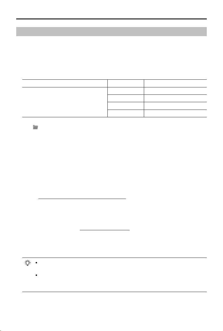
48
©
2021 DJI All Rights Reserved.
DJI TERRA
User Manual
LiDAR Point Cloud Processing
Reconstruction Procedure
1. Similar with 2D and 3D reconstructions, users can create a new LiDAR Point Cloud Processing
mission by creating a new mission or importing a mission.
Refer to the size of the raw point cloud data corresponding to the following computer
congurations to make sure that there is an adequate amount of raw LiDAR point cloud data and
that the point cloud data can be processed smoothly.
Graphic Card RAM Max Size of Raw Point Cloud
GeForce GTX 1050Ti with 4GB of VRAM
16GB 4GB
32GB 8GB
64GB 16GB
128GB 32GB
2. Click
and select the folder with the corresponding date to add the LiDAR point cloud data to
DJI Terra. The folder must contain the les with the sufx CLC, CLI, CMI, IMU, LDR, RTB, RTK,
RTL, and RTS. Any JPEG les in the folder are not required to be imported.
3. Select the point cloud density: high density refers to the original sampling rate, which uses 100%
of the point cloud data for processing. The processing results will be of the highest quality but
will take the longest amount of time to process. Medium density uses 25% of the point cloud
data for processing. The processing results will be of medium quality and will take a medium
amount of time to process. Low density uses 6.25% of the point cloud data for processing. The
processing result will be of lower quality but will take the shortest amount of time to process.
4. Set the output coordinate system: same as 2D and 3D reconstructions. Users can set the output
coordinate system so that the results will be converted to the corresponding coordinate system.
Refer to “Output Coordinate System Settings” on p. 44 for more information.
5. Parameter Settings
Optimize Point Cloud Accuracy: if enabled, the software will optimize point cloud data collected
at different times during processing for higher overall consistency and accuracy. This is a
premium feature included in DJI Terra Pro and more advanced versions. Purchase and activate
a license before use. Refer to “More Functions” on p. 50 for more information on purchasing and
activating licenses.
Point Cloud Effective Distance: set the distance between the LiDAR sensor and point cloud data.
Only point cloud data within the effective distance will be used for processing. LiDAR point data
beyond the effective distance will be ltered out.
Users can set the point cloud effective distance to lter out data in the background
when reconstructing a target area that is at a close distance.
How to set the distance value: estimate the max straight line distance between the
LiDAR sensor and the corresponding target area. Set this distance as the point cloud
effective distance.
©
2021 DJI All Rights Reserved.
49
DJI TERRA
User Manual
6. Select the reconstruction file formats. If point cloud is enabled, a 3D point cloud will be
generated. The default le format for the point cloud is pnts. The point cloud can be set to other
formats. LAS refers to the ASPRS LAS format for a 3D point cloud file. PLY refers to the ply
format for a non-LOD 3D point cloud le. PCD refers to the pcd format for a non-LOD 3D point
cloud le, which is used in Point Cloud Library and can be viewed using CloudCompare. S3MB
refers to the s3mb format for the SuperMap LOD 3D point cloud le.
7. Click “Start Processing.” The progress bar at the bottom will show the reconstruction progress.
Click “Stop” to stop processing and the progress will be saved. If processing is restarted after
stopping, DJI Terra will track back slightly from the saved progress before continuing.
8. Multiple processing missions can be started, but only one processing mission can be processed
at once. Any remaining processing missions will be queued.
9. After processing, users can translate and rotate the processing results and zoom in or out to
view it from different angles. The operations are the same as with 3D models. Select different
display styles at the bottom of the screen.
RGB: displays real color.
Reectance: displays corresponding color according to the reectance of objects with values
between 0 and 255. 0 to 150 corresponds to the reectance within the range of 0 to 100% in the
Lambertian reection model. 151 to 255 corresponds to the reectance of target objects with
retroection properties.
Height: displays the corresponding color according to the height of the point cloud.
Returns: display the corresponding color according to the number of returns when collecting
data.
10. Click “Quality Report” to view and save a report in html format. The report includes an overview
of the raw data information, software parameters, reconstruction file format, and point cloud
processing time. Refer to the document How to Read a DJI Terra Quality Report on the ofcial
DJI website for more information.
11. Click
on the right of Annotation and Measurement bar to add annotations and perform a
variety of measurements to the point cloud processing results. The operations are same as with
3D models. Refer to “Annotation and Measurement” on p. 42 for more information.
File Storage Path of LiDAR Point Cloud Results
The default storage path of the LiDAR point cloud results is shown below. The cache directory can
be changed in Settings.
C:\Users\<computer name>\Documents\DJI\DJI Terra\<DJI account name>\<mission
code>\<lidars>
On the processing page, users can open the current mission folder using the keyboard shortcut
“Ctrl+Alt+F”.
If PC GS Pro has been used on your computer, after DJI Terra has been installed, the
cache directory will still be as follows:
C:\Users\<computer name>\Documents\DJI\Groundstation\Missions\<DJI account name>
The mission code is the number generated by the software automatically when a mission
is created. It cannot be changed by users.
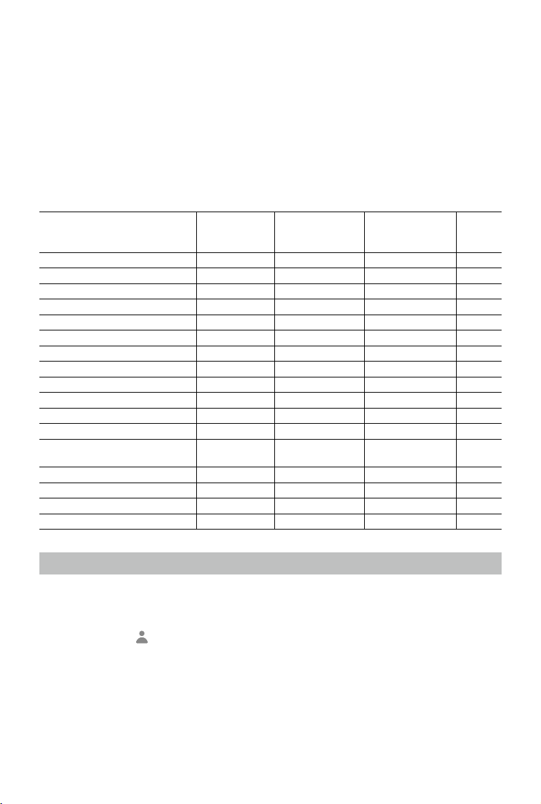
50
©
2021 DJI All Rights Reserved.
More Functions
KML les can be imported onto DJI Terra to add waypoints or edge points of a ight area. In a
Waypoints mission, 2D / 3D Mission Planning based on an existing or newly created reconstruction
is available. For Reconstruction missions, there are various functions available such as 2D Map
Reconstruction (urban scenes), Output Coordinate System Selection, ROI Reconstruction, Multi-
GPU Reconstruction GCP Management, 3D Model Reconstruction, and LiDAR Point Cloud
Accuracy Optimization. Users can also purchase the Cluster version to use multiple devices in the
local network for cluster reconstruction. These are premium features. Purchase a license according
to the features you require.
See the table below which provides an overview of DJI Terra's more advanced features and funcrions.
Features
Agriculture
(Online Version)
Pro
(Online and Ofine
Versions)
Electricity
(Online and Ofine
Versions)
Cluster
(Ofine
Version)
Real-time 2D Mapping √ √ √ √
Agricultural application √ √ √ √
2D Reconstruction (Field/Fruit Tree) √ √ √ √
2D Multispectrual Reconstruction √ √ √
KML le import √ √ √
2D Reconstruction (Urban) √ √ √
Output Coordinate System √ √ √
Image POS data import √ √ √
ROI Reconstruction √ √ √
3D Reconstruction (Normal/Circle) √ √ √
3D Mission planning √ √ √
Multi-GPU Reconstruction √ √ √
LiDAR Point Cloud Accuracy
Optimization
√ √ √
GCP √ √ √
3D Reconstruction (Power Lines) √ √
Detailed Inspection √ √
Cluster Reconstruction √
Purchase Licenses
Users can purchase online licenses for DJI Terra Pro or Electricity version on the product page on the
ofcial DJI website. DJI will send the activation code via an email once purchased successfully. See the
details below.
Launch DJI Terra >
> Activated License(s) > Buy New License(s). Users will be redirected to
the ofcial DJI website to get the details about the functions of different versions. Users can also
be redirected to the ofcial DJI website by clicking the corresponding button where Real-Time 2D
Mapping, Real-Time 3D Mapping, Reconstruction, Output Coordinate System, GCP Management,
Agriculture, KML File Import, or 2D/3D function is required.
To purchase DJI Terra Pro or Electricity, visit the DJI Terra product page at https://www.dji.com/
dji-terra . Input your information on the contact form, and then wait for a DJI authorized dealer to
respond to your request.
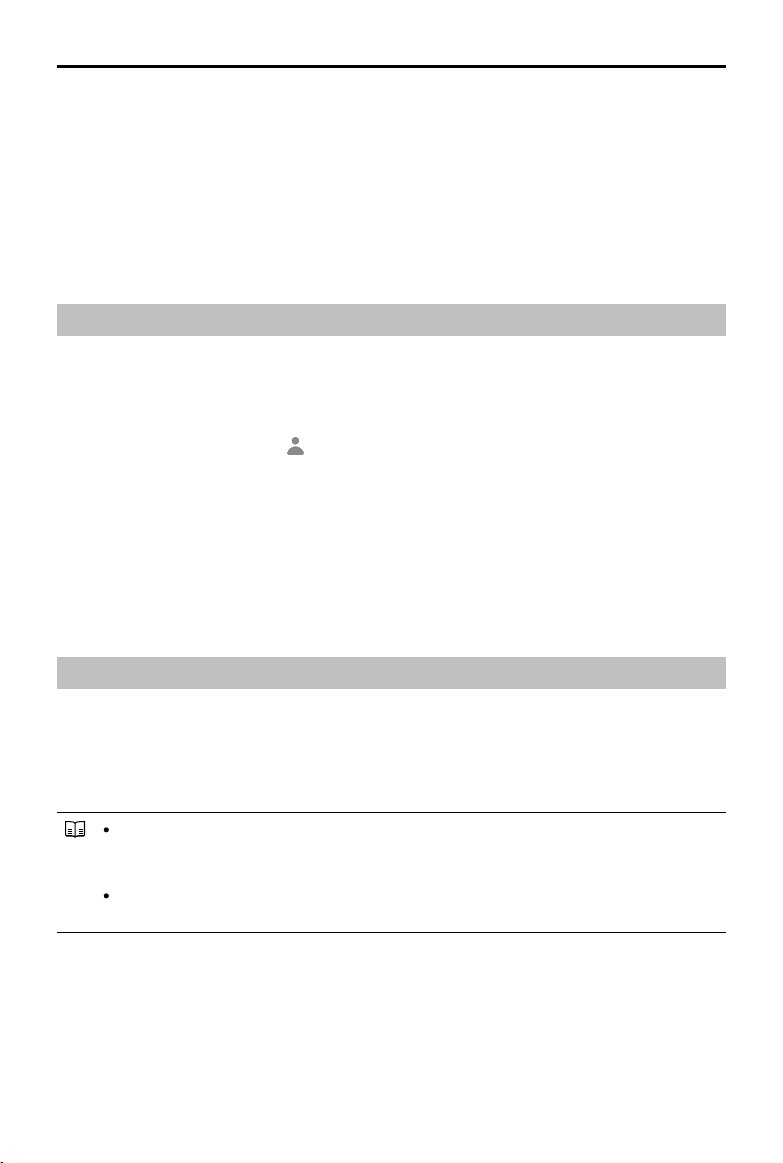
©
2021 DJI All Rights Reserved.
51
DJI TERRA
User Manual
Pro version and Electricity version support ofine login. Users can contact an authorized DJI dealer
via the product page on the ofcial DJI website to purchase an ofine license. DJI will send the
exchange code via an email once purchased successfully.
Cluster version only supports offline login. Users can contact an authorized DJI dealer via the
product page on the ofcial DJI website to purchase an ofine license and choose from different
worker device quotas. DJI will send the exchange code via an email once purchased successfully.
Refer to the Preparation Before Using DJI Terra for more information on how to activate the ofine
license and bind a device.
Activate Online Licenses and Bind Devices
To use the licenses with the desired DJI accounts and on the desired computers, license activation
and device binding are required. Activate licenses in DJI Terra or via an activation link. Each license
can be bound to up to three computers. Contact DJI Support to unbind the license if needed.
1. Enter the activation page via the two methods below:
DJI Terra: Launch DJI Terra >
> Activated License(s) > Activate a New License. A window
prompt will appear.
Activation Link: Visit https://license.dji.com/en
2. Input the activation code you received and the desired DJI account that you want to use the
license with, then click “Activate.”
3. After successful activation, view the ID, expiry time, and device binding status of the license. If
activating the license via the link, re-enter the Activated License(s) page to view the information.
4. Click “Device Binding” and then click “Bind” to bind the license to the current computer used.
“Bound” will be displayed next to the license of the corresponding ID in Activated License(s).
Cluster Reconstruction
Environment Setup
Refer to Preparation Before Using DJI Terra for more information on required devices and how to
set up Cluster version.
Usage
Control device: the device running DJI Terra Cluster. In the control device, users can
congure cluster reconstruction settings, select worker devices, and view the status of
reconstruction missions.
Worker devices: the devices in the local network that can be assigned by the control
device to reconstruction missions.
Control Device Operations
Make sure you have imported the license, activated Cluster version, and logged in ofine.
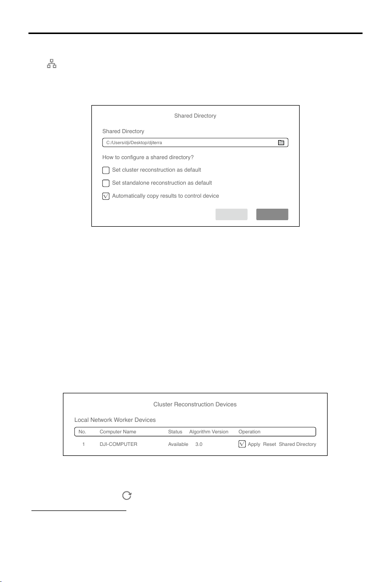
52
©
2021 DJI All Rights Reserved.
DJI TERRA
User Manual
Cluster Reconstruction Settings
Click
on the upper right corner on the home page of DJI Terra to enter the cluster reconstruction
settings.
Shared Directory
Shared Directory
Shared Directory
C:/Users/dji/Desktop/djiterra
How to configure a shared directory?
√
Set cluster reconstruction as default
Set standalone reconstruction as default
Automatically copy results to control device
Cancel OK
1. Shared Directory
Set the shared directory. It is recommended to set the directory to the network-attached storage
(NAS). Refer to Preparation Before Using DJI Terra for more information.
2. Reconstruction and Copy Selection
Set cluster reconstruction as default: When checked, the software will use cluster reconstruction
as default after starting reconstruction.
Set standalone reconstruction as default: When checked, the software will use standalone
reconstruction as default after starting reconstruction.
Automatically copy results to control device: When checked, the reconstruction results will be
copied from the NAS to the control device. When unchecked, the results will only be stored on
the NAS.
Cluster Reconstruction Devices
Cluster Reconstruction Devices
Local Network Worker Devices
No. Computer Name Status Algorithm Version Operation
1 DJI-COMPUTER Available 3.0
√
Apply Reset Shared Directory
After entering the page, the software will automatically search for the enabled worker devices in
the current local network and list the name, status, algorithm version, and corresponding operation
of the found devices. Click
to refresh the search results and status of worker devices. Refer to
“Worker Devices Operations” for more information on how to enable worker devices.
1. Computer Name: displays the name of the worker device.
2. Status: displays if the worker device is available or busy. Only available devices can be
selected.
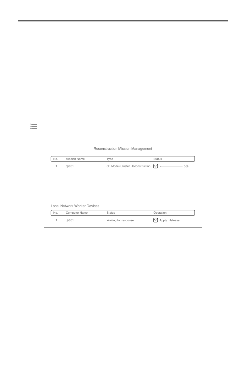
©
2021 DJI All Rights Reserved.
53
DJI TERRA
User Manual
3. Algorithm Version: displays the algorithm version of the worker device. Blue indicates that it
is the same version as the control device, while red indicates that it is a different version from
the control device. Only devices with the same algorithm version as the control device can be
selected.
4. Operations
Apply: check the box to select the device as a worker device to use for cluster reconstruction.
Reset: click to reset the worker device to available if it is incorrectly displayed as busy.
Shared Directory: indicates whether the shared directory settings are the same between the
worker device and control device. Blue indicates the settings are the same while red indicates
the settings are different. A device can only be selected as a worker device if it has the same
shared directory as the control device.
Reconstruction Mission Management
Set cluster reconstruction as default, select worker devices, and start reconstruction missions.
Click
on the home page to enter the reconstruction mission management page.
Reconstruction Mission Management
No. Mission Name Type Status
1
1
dji001 3D Model-Cluster Reconstruction
√
5%
Local Network Worker Devices
No. Computer Name Status Operation
dji001 Waiting for response
√
Apply Release
The upper section of the page displays the queue of reconstruction missions. Users can view the
name, reconstruction type, and status of each mission.
The lower section of the page lists the local network worker devices. The display is similar with
the one in the cluster reconstruction devices page in the cluster reconstruction settings. When the
status of the worker device is abnormal, click Release under the device operations to release the
worker device. A worker device cannot be used for the same reconstruction mission again once it is
released.
Worker Device Operations
The DJI Terra Engine will be installed automatically to the worker device when DJI Terra is installed.
Users can nd DJITerraEngine.exe in the Cluster folder in the installation directory or go to the DJI
Product folder in the Start menu.
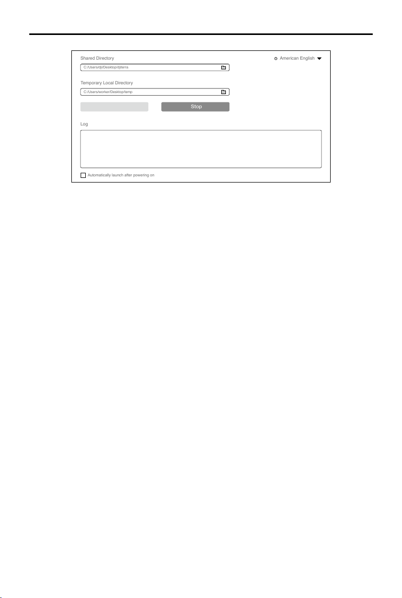
54
©
2021 DJI All Rights Reserved.
DJI TERRA
User Manual
Shared Directory
C:/Users/dji/Desktop/djiterra
Temporary Local Directory
C:/Users/worker/Desktop/temp
Automatically launch after powering on
Start
Stop
Log
American English
1. Shared Directory: set the shared directory. The setting must be same as the setting in the control
device.
2. Temporary Local Directory: used for temporary storage while the worker device is performing a
reconstruction. Select a local directory in the worker device as the temporary local directory and
make sure that there is enough disk space.
3. Start/Stop: to start or stop the worker device. Once started, a worker device can be searched for
and used by the control device in the local network.
4. Log: print the logs of the worker device.
5. Language Switch: click the language switch on the upper right corner to switch language.
6. Automatically launch after powering on: if enabled, the DJI Terra Engine will launch automatically
after the worker device is powered on.
Cluster Reconstruction Procedure
1. Make sure you have already congured the parameters related to cluster reconstruction and
selected the worker devices.
2. Start reconstruction following the normal procedure for reconstruction missions and make sure
to use cluster reconstruction.
3. View the mission progress rate and status of worker devices in reconstruction mission
management.
4. If automatically copying results to the control device is disabled and the control device is still
connected to the shared directory after the cluster reconstruction, users can view the reconstruction
results in DJI Terra and also in the les in the corresponding folders.
If automatically copying results to the control device is enabled, users can view the reconstruction
results in DJI Terra without being connected to the shared directory and also in the files in the
corresponding folders.
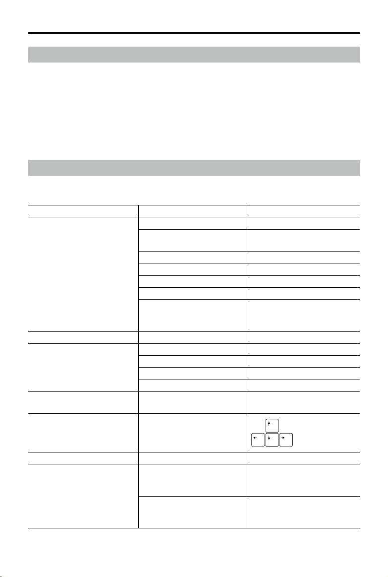
©
2021 DJI All Rights Reserved.
55
DJI TERRA
User Manual
View and Export Logs
DJI Terra will generate a log file when performing a mission. If there is a software error or the
software crashes during a mission, users can have access to the corresponding log file in the
storage path below according to the time the mission was performed. Then export it and send to
DJI Support for analysis.
C:\Users\<computer name>\AppData\Roaming\DJI Terra\log
Users can open the log storage directory using the keyboard shortcut "Ctrl+Alt+L" after launching
DJI Terra.
Software Shortcuts
In DJI Terra, users can perform some functions and operations using shortcuts. The table below
lists the shortcuts that can be used in different pages in DJI Terra.
Page Functions / Operations Shortcuts
Mission Library
Create mission Ctrl+N
Switch mission type when
creating a mission
Tab
Switch mission type Tab
Switch mission Up:
↑
, Down:
↓
Switch operation for mission Left:
←
,Right:
→
Delete mission Delete
Select all missions when
deleting or exporting multi
missions
Ctrl+A
Map Map Zoom In/Out Zoom In: +, Zoom Out: -
Mission Editing
Save the current mission Ctrl+S
Delete the selected waypoint Delete
Switch parameter Tab
Adjust parameter value More:
↑
, Less:
↓
Waypoints or Detailed
Inspection Mission Editing
Switch waypoint
Previous: Ctrl+
←
Next: Ctrl+
→
Detailed Inspection Mission
Editing
Adjust waypoint location
Reconstruction Open the current mission folder Ctrl+Alt+F
3D Model Map
Switch model display view
Orthographic projection: F1
Front view: F2
Top view: F3
Switch between
aerotriangulation, point cloud,
and model result
F4

DJI TERRA
User Manual
This content is subject to change.
Download the latest version from
http://www.dji.com/dji-terra
Copyright © 2021 DJI All Rights Reserved.
If you have any questions about this document, please contact
DJI by sending a message to [email protected].
Photo Management
Select the photos in series in
the same folder
Shift+click the rst and last
photo
Delete multi photos in the same
folder
Delete
GCP Management
Edit the name of the selected
GCP
Enter
Switch GCP Up:
↑
, Down:
↓
Switch parameter Tab
Annotation and Measurement
Switch object for measurement Tab
Expand or collapse
measurement results
Ctrl+Q
Measurement Result
Management
Select results in series
Shift+click the rst and last
measurement results
Select all results Ctrl+A
Flight Route Plan in Agricultural
Application
Delete the selected farmland
point or calibration point
Delete
Switch between farmland points
or calibration points
Tab
Save the current mission Ctrl+S
Show or hide recognition result F5
Modify fruit trees recognition
result
Ctrl+Left Mouse Button
Show or hide prescription map F6
Enable or disable obstacle
avoidance
F7
Show or hide ight route F8
All Pages Open the log storage directory Ctrl+Alt+L