Loading ...
Loading ...
Loading ...
9
INSTALLATION INSTRUCTIONS
WARNING!
This product is heavy and requires two persons for installation.
Installation work and electrical wiring must be done by qualified person(s)
inaccordance with all applicable codes and standards.
Failure to install the screws or fixing device in accordance with these instructions
mayresult in electrical hazards
IMPORTANT!
Wear gloves to protect against sharp edges.
The manufacturer is not liable for any damage caused by not following theseinstructions.
Installation
1 Preparing for installation:
Before installing your rangehood:
Please read the instructions carefully.
Unpack the rangehood.
Ensure that the voltage (V) and the frequency (Hz) indicated on the serial plate
match the voltage and frequency at the installation site.
Check that all functions are working.
Check that the area behind the installation surface to be drilled is clear of any
electrical cables or pipes, etc.
The rangehood surfaces can be damaged during installation if grazed or knocked
by tools. Please take care to protect the surfaces during installation.
Protect the cooktop surface with cardboard, or the like, to prevent damage occurring
whilst the rangehood is being installed above.
Temporarily mark the height of the bottom of the rangehood and the centre of the
cooktop on the wall according to the information given in the ‘Installation instructions
– Height of rangehood’ section.
The wall used for mounting the rangehood should have sufficient strength and a
flat surface.
2 Attach chimney brackets and rangehood mounting screws to the wall
Attach the chimney bracket and upper
chimney bracket in the location shown
in Fig.2 (refer to page 10) and 3 (refer
to page11). Use the 30 mm screws (and
expansion plugs if attaching to masonry).
Attach the upper rangehood mounting
screws in the locations shown in Fig.2
(refer to page 10) and 3 (refer to page 11).
Use the 30 mm screws (and expansion
plugs if attaching to masonry).
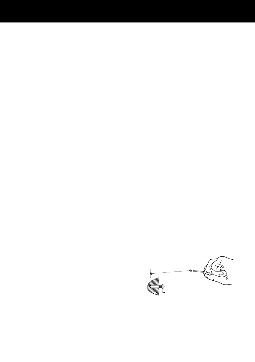
Ensure that there is a 2 mm gap between
the screw head and the wall (see Fig.1).
Fig.1
2 mm
Loading ...
Loading ...
Loading ...