Window Air Conditioner
MAW
USER MANUAL
Warning notices: Before using this product, please read this manual carefully and keep it for future reference.
MAW08V1QWT
MAW10V1QWT
MAW12V1QWT
MAW08V1QWT-T
Download the app
& activate product

WARRANTY ................................................................................................................................39
2
CONTENTS
THANK YOU LETTER
Thank you for choosing Midea! Before using your new Midea product, please read this manual
thoroughly to ensure that you know how to operate the features and functions that your new air
conditioner offers in a safe way.
THANK YOU LETTER ...............................................................................................................2
SAFETY INSTRUCTIONS ........................................................................................................3
PRODUCT INSTALLATION ....................................................................................................7
OPERATION INSTRUCTIONS ..............................................................................................17
REMOTE CONTROL AND APP INSTRUCTIONS .........................................................22
CLEANING AND MAINTENANCE......................................................................................36
TROUBLESHOOTING TIPS ..................................................................................................37
TRADEMARKS, COPYRIGHTS AND LEGAL STATEMENT .......................................40
DATA PROTECTION NOTICE ............................................................................................41
3
SAFETY INSTRUCTIONS
Intended Use
The following safety guidelines are intended to prevent unforeseen risks or damage from unsafe or incorrect
operation of the appliance. Please check the packaging and appliance on arrival to make sure everything
isintacttoensuresafeoperation.Ifyoufindanydamage,pleasecontacttheretailerordealer.Pleasenote
modificationsoralterationstotheappliancearenotallowedforyoursafetyconcern.Unintendedusemaycause
hazards and loss of warranty claims.
Explanation of symbols
Read these operating instructions carefully and attentively before using/commissioning the unit and keep them
in the immediate vicinity of the installation site or unit for later use!
CAUTION
• For support, please call the Service Center at 1-866-646-4332.
• This appliance is not intended for use by people (including children) with reduced physical, sensory, or
mental capabilities or lack of experience and knowledge, unless they have been given supervision or
instruction concerning use of the appliance by a person responsible for their safety.
• Children should be supervised to ensure that they do not play with the appliance.
• The appliance shall be installed in accordance with national wiring regulations.
• Do not operate your air conditioner in a humid room such as a bathroom or laundry room.
Warning
Thissymbolshowsthatthisapplianceusedaflammablerefrigerant.Iftherefrigerantisleaked
andexposedtoanexternalignitionsource,thereisariskoffire.
Caution
This symbol shows that the operation manual should be read carefully.
Caution
This symbol shows that a service personnel should be handling this equipment with reference
to the installation manual.
Caution
This symbol shows that information is available such as the operating manual or installation
manual.
Warning
The signal word indicates a hazard with a medium level of risk which, if not avoided, may result
in death or serious injury.
Caution
The signal word indicates a hazard with a low degree of risk which, if not avoided, may result in
minor or moderate injury.
Attention
The signal word indicates important information (e.g. damage to property), but not danger.

4
WARNING
• Be sure the air conditioner has been securely and correctly installed according to the installation instructions
in this manual. Save this manual for possible future use in removing or installing this unit.
• Plug in power cord plug properly.
Otherwise,itmaycauseelectricshockorfireduetoexcessheatgeneration.
• Do not modify power cord length or share the outlet with other appliances as it may cause electric shock or
fire due to overheating.
• Always ensure effective grounding.
Incorrect grounding may cause electric shock.
• Unplug the unit if you notice unusual sounds or smells or smoke coming from it.
Adamagedproductmaycausefireandelectricshock.
• Ventilate room before operating the air conditioner if there is a gas leakage from another appliance.
• Do not operate or stop the unit by inserting or pulling out the power cord plug.
• Do not operate with wet hands or in very humid environments.
It may cause electric shock.
• Do not allow water to come into contact with any electric parts.
It may cause failure or electric shock.
• Do not use the socket if it is loose or damaged.
Itmaycausefireandelectricshock.
• Do not use or keep the power cord close to heating appliances.
Itmaycausefireandelectricshock.
• Do not use any devices or materials for installation that are not recommended in this manual.
• Do not disassemble or modify unit.
It may cause failure and electric shock.
• Do not damage or use an alternate power cord.
Itmaycausefireandelectricshock.
If the power cord is damaged, it must be replaced by the manufacturer or an authorized service center or a
similarlyqualifiedpersoninordertoavoidahazard.
• Donotdirectairflowstraightintopersonstoavoidpossiblehealthhazard.
• Do not open the unit during operation.
It may cause electric shock.
• Donotusethepowercordnearflammablegasorcombustibles,suchasgasoline,benzene,thinner,etc.
Itmaycauseanexplosionorfire.
• Do not let children hang on the air conditioner or bracket.
A serious injury may occur.
• Avoidfirehazardorelectricshock.Donotuseanextensioncordoranadaptorplug.Donotremoveany
prongs from the power cord.
• Besuretheairconditionerisproperlygrounded.Tominimizeshockandfirehazards,propergroundingis
important. The power cord is equipped with a three-prong grounding plug for protection against shock
hazards.
• Your air conditioner must be used in a properly grounded wall receptacle. If the wall receptacle you intend
touseisnotadequatelygroundedorprotectedbyatimedelayfuseorcircuitbreaker,haveaqualified
electrician install the proper receptacle. Ensure the receptacle is accessible after the unit installation.
• Be sure the electrical service is adequate for the model you have chosen. This information can be found on
the serial plate, which is located on the side of the cabinet and behind the grille.
• Do not drink the drain water. It may contain mold and bacteria that can lead to death if ingested.
fiames or an operating gas appliance) or an ignition source (for example, an operating electric heater) close
5
CAUTION
• Whentheairfilteristoberemoved,donottouchthemetalpartsoftheunit.
It may cause injury.
• When the unit needs cleaning, switch off, and turn off the circuit breaker.
Donotcleanunitwhenpowerisonasitmaycausefire,electricshockorinjury.
• Do not place obstacles around air inlets or inside of air outlet.
It may cause failure or accident.
• Clean with a soft cloth only. Do not use strong detergents that contain wax or thinners as it may damage
the product.
• Use caution when unpacking and installing. Sharp edges could cause injury.
• Do not clean the air conditioner with water.
Water may enter the unit and degrade the insulation which could lead to electric shock.
• Donotputapetorhouseplantwhereitwillbeexposedtodirectairflow.
This could injure the pet or harm the plant.
• Hold the plug by the head of the power plug when taking it out.
Otherwise, it may cause electric shock and damage.
• Ensure that the installation is properly secured to prevent the product from potentially falling.
• Do not place heavy objects on the power cord and ensure that the cord is not compressed.
Otherwise,thereisdangeroffireorelectricshock.
• If water is spilled on the unit, turn off the unit and switch off the circuit breaker. Isolate supply by taking the
power-plugoutandcontactaqualifiedservicetechnician.
• Donotuseneargasstoveorothergasburningappliances,asairflowmayaffectgascombustion.
• Do not use for any purpose other than room comfort.
Do not use this air conditioner to preserve precision devices, food, pets, plants, and art objects. It may cause
deterioration.
• Turn off the main power switch if the unit is not to be used for an extended time.
• Alwaysinsertthefilterssecurely.Cleanfilteronceeverytwoweeks.
Operationwithoutfiltersmaycausefailure.
WARNING
• Do not try to accelerate the defrosting process or methods of cleaning that are not recommended by the
manufacturer.
• The appliance shall be stored in a room without a continuously operating ignition source (for example, open
to the appliance. The appliance shall also be stored in a room without ignition sources.
• Do not pierce or burn.
• Be aware that the refrigerants may not contain an odor.
• Keep ventilation openings clear of obstruction.
• Unit is only to be serviced by a Midea authorized servicer, please call Customer Service at 1-866-646-4332
for support.
• Flammable refrigerant R32 is used within air conditioner. Please follow the instructions carefully to handle,
install, clean, and service the air conditioner to avoid damage or hazard. Do not dispose of air conditioner in
regulartrash.Contactqualifiedagencyforproperdisposal.
• Noopenfireordevicesthatgeneratespark/arcingshallbearoundtheairconditionertoavoidcausing
ignitionoftheflammablerefrigerantused.Pleasefollowtheinstructionscarefullytostoreormaintaintheair
conditioner to prevent mechanical damage from occurring.
6
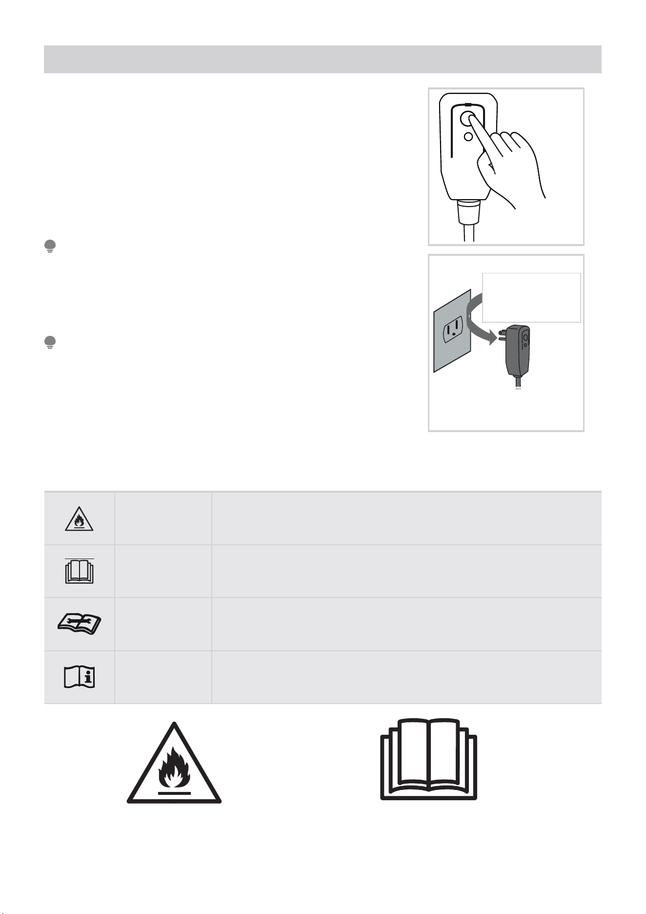
Operation of Current Device
The power supply cord contains a current measuring device that detects
damage to the power cord. Test your power supply cord as follows:
1. Plug in the air conditioner.
2. The power supply cord will have TWO buttons on the plug head.
Press the TEST button. You will notice a click as the RESET button
pops out.
3. Press the RESET Button. You will notice a click as the button engages.
4. The power supply cord is now supplying electricity to the unit. (On
some products this is also indicated by a light on the plug head.)
RE SE T
TE ST
Plug in &
press RESET
The power supply cord with this air conditioner contains a current
detectiondevicedesignedtoreducetheriskoffire.
In the event that the power supply cord is damaged, it can not be
repaired. It must be replaced with a cord from the manufacturer.
NOTE
• Do not use this device to turn the unit on or off.
• Always make sure the RESET button is pushed in for correct
operation.
• The power supply cord must be replaced if it fails to reset when either
the TEST button is pushed, or it can not be reset. Please contact
Customer Service.
NOTE
Do not, under any
circumstances, cut,
remove or bypass
the grounding prong.
Power supply cord with
3-prong grounding plug and
current detection device.
Grounding type wall receptacle
Do not, under any
circumstances, cut,
remove or bypass
the grounding prong.
Explanation of symbols displayed on the unit
WARNING
Thissymbolshowsthatthisapplianceusedaflammablerefrigerant.Ifthe
refrigerant is leaked and exposed to an external ignition source, there is a
riskoffire.
CAUTION This symbol shows that the operation manual should be read carefully.
CAUTION
This symbol shows that a service personnel should be handling this
equipment with reference to the installation manual.
CAUTION
This symbol shows that information is available such as the operating
manual or installation manual.
Caution:Riskoffire/flammablematerials
(Required for R32/R290 units only)
IMPORTANT NOTE: Read this manual carefully before
installing or operating your new air conditioning unit. Make
sure to save this manual for future reference.
7
PRODUCT INSTALLATION
Installation Video
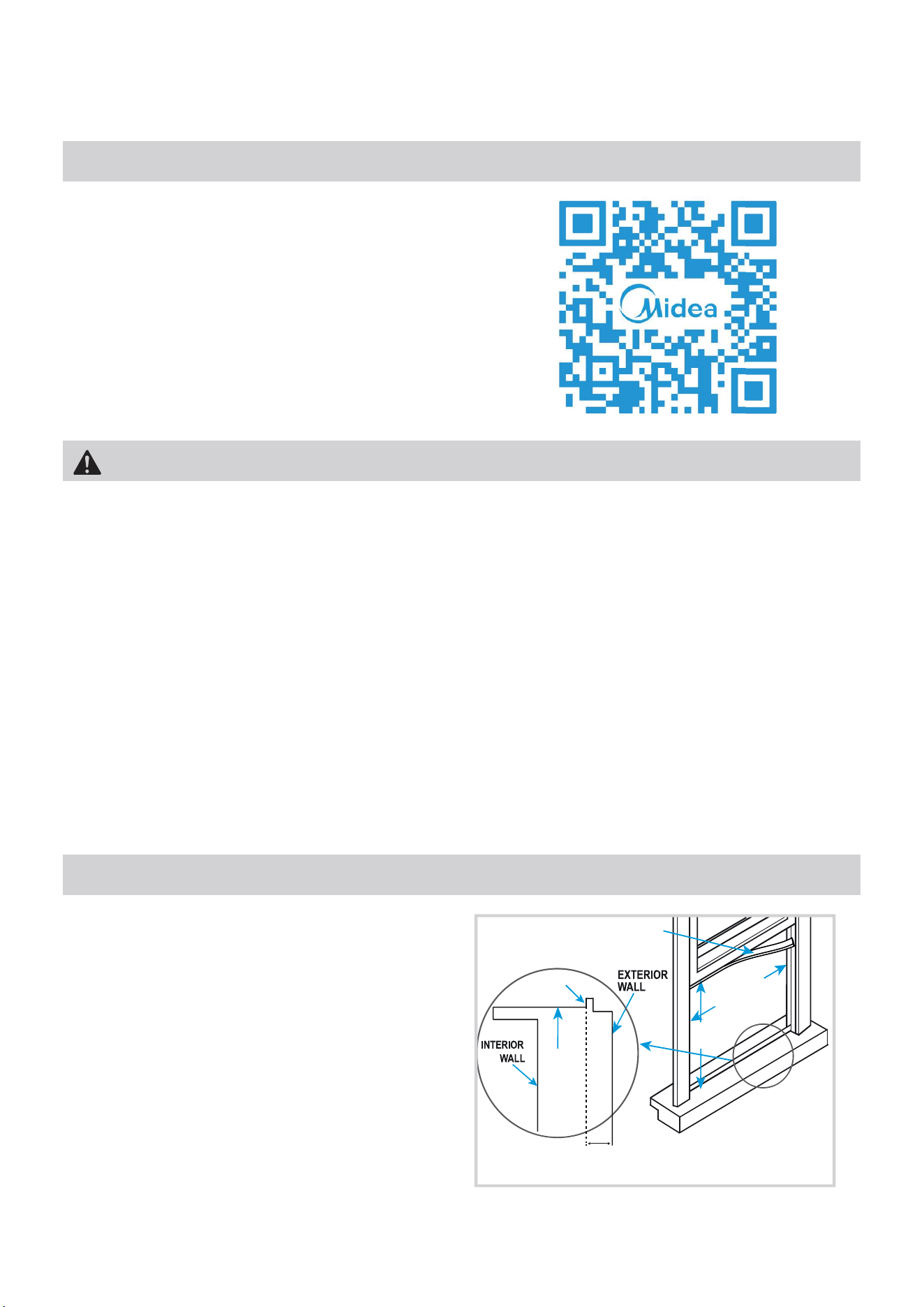
Window Requirements
Scan the QR code with your mobile device to watch an
installation video of the Midea U.
WARNING - Before You Begin
Read these instructions completely and carefully.
• IMPORTANT - Save these instructions.
• IMPORTANT - Observe all governing codes and ordinances.
We recommend that two people install this product.
Proper installation is the responsibility of the installer.
Product failure due to improper installation is not covered under the Limited Warranty.
You MUST use all supplied parts and use proper installation procedures as described in these instructions when
installing this air conditioner.
Do not, under any circumstances, cut or remove the third (ground) prong from the power cord.
Do not change the plug on the power cord of the air conditioner.
Aluminumhousewiringmaypresentspecialproblems-consultaqualifiedelectrician.
Whenhandlingtheairconditioner,becarefultoavoidcutsfromsharpmetaledgesandaluminumfinsonfront
and rear coils. Please wear cut-resistant gloves.
Bracket should only be used for its intended purpose. If not, the warranty will be voided.
Your air conditioner is designed to install in standard
double hung windows with opening widths of 22 to
36 inches (558mm to 914mm) and a window height of
13.75” (349mm).
Vinyl-Clad Windows
INNER
WINDOW
SILL
13.75" min
(349 mm)
22" to 36"
(558 mm
to 914mm)
SEAL FOAM
Note: Midea U bracket works on walls with
thickness 3 to 10.5 inches from inside of
window to outside wall.
Vinyl lip
8
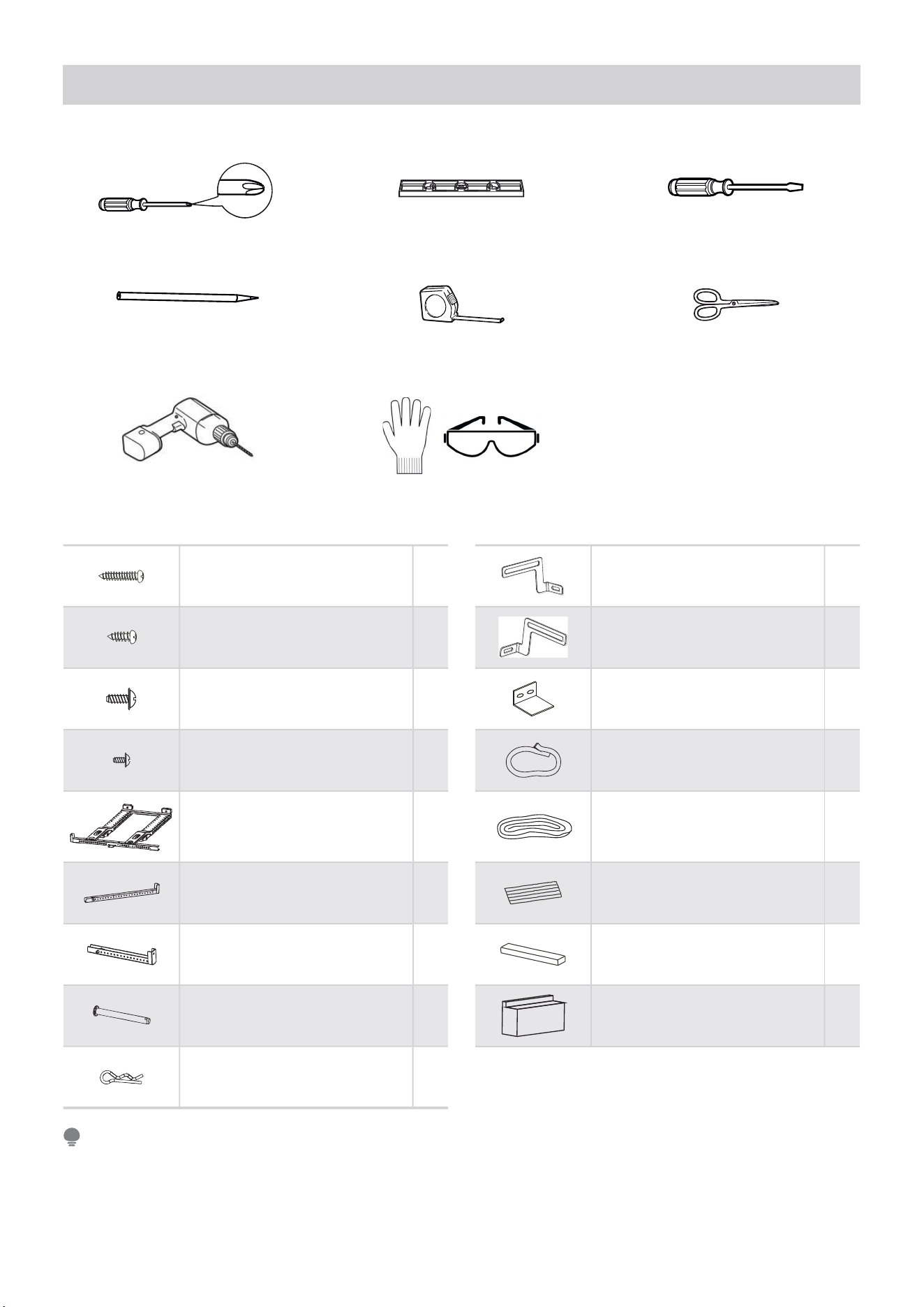
Tools You Will Need
1” Type A Screw 2*
1/2” Type A Screw 3*
1/2” Type B Screw 2*
1/4” Type B Screw 2*
1tekcarB niaM
Right Extension Arm
(For 26”-36” windows)
1
Right Extension Arm – Short
(For 22”-26” windows)
1
Main Support Pin 2*
*2niP rettoC
Open Window Bracket – RH 1
Open Window Bracket – LH 1
Window Sash Lock 1
Window Sash Foam 1
Window Sealing Foam 1
Bracket Sealing Foam 1
Additional Side Arm Foam 2
Side Arm Foam 2
Phillips Screwdriver
Pencil
Drill and 1/8” drill bit
Level
Ruler or tape measure
Proper PPE
Flathead Screwdriver
Scissors or knife
Installation Hardware
* Denotes extra hardware provided in separate bag.
Save carton and these Installation Instructions for future reference. The carton is the best way to store unit
during winter, or when not in use. If any piece of hardware is missing, DO NOT INSTALL THE PRODUCT, and call
customer service at 1-866-646-4332.
NOTE
9
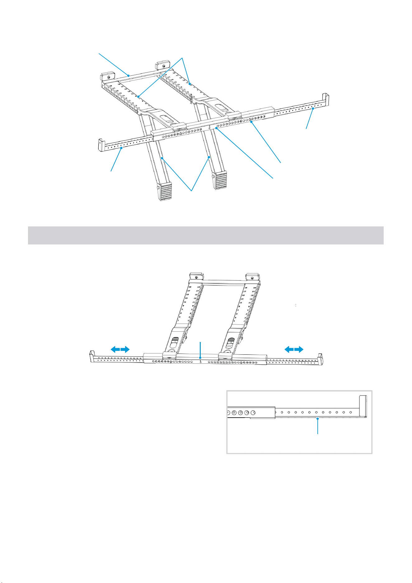
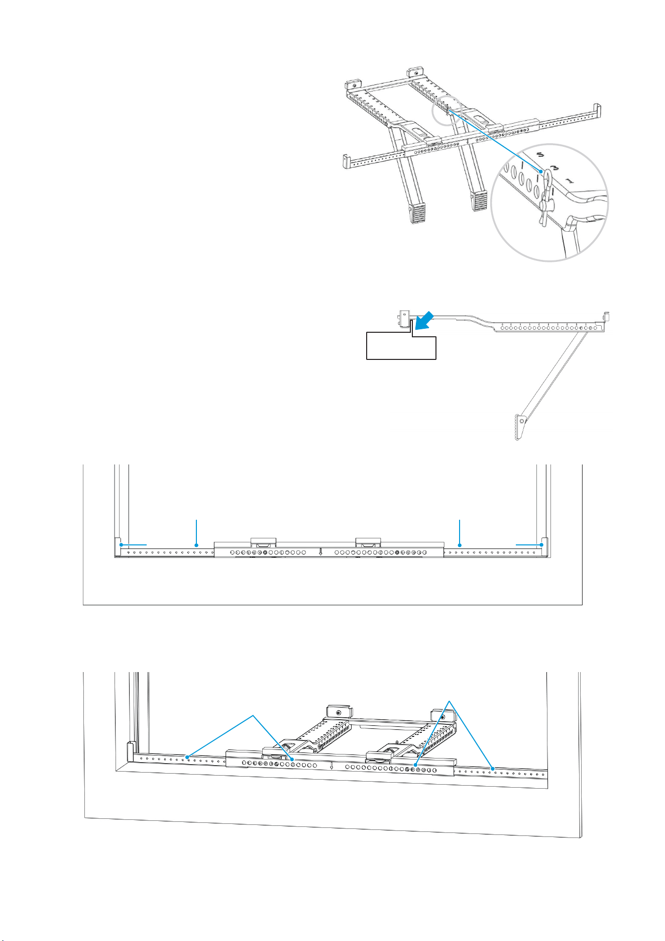
1. Prepare the Bracket – Install Video Time 1:48
Remove the top foam insert containing the bracket and hardware from the carton.
A. Measure the inside opening of your window sill and
use that distance to set the total width of the bracket
Extension Arms. To adjust the extension arms, press
the Spring Push Pin, slide the Left Extension Arm out
and then install the Right Extension Arm. Use the
short arm for 22-26” windows, and the long arm for
26-36” windows.
B. Apply Bracket Sealing Foam strips to the bottom of
the bracket as shown. Repeat on both sides.
Rear Cross
Brace
Left
Extension
Arm
Main
Support
Angled
Support Arms
Horizontal Bracket
Spring Push Pin
Right
Extension
Arm
Fig. 1
Center AdjustAdjust
Fig. 2
Apply Bracket
Sealing Foam
Fig. 3
Note The left arm moving to the
right side pin holes when adjusting
for the 22" windows.
10
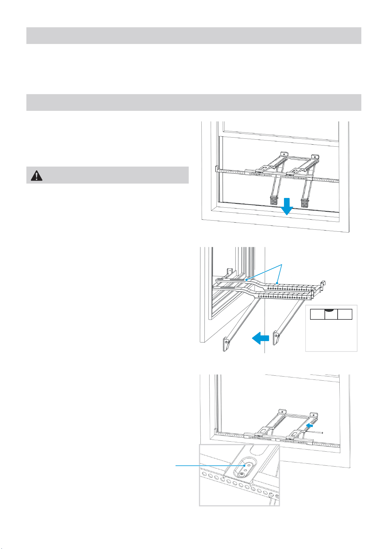
3. Install Support Bracket – Install Video Time 3:12
A. Install the Main Support Bracket into the window
opening. Ensure that the Horizontal Bracket and
Extension Arms are located on the indoor side of
the window.
Fig. 4
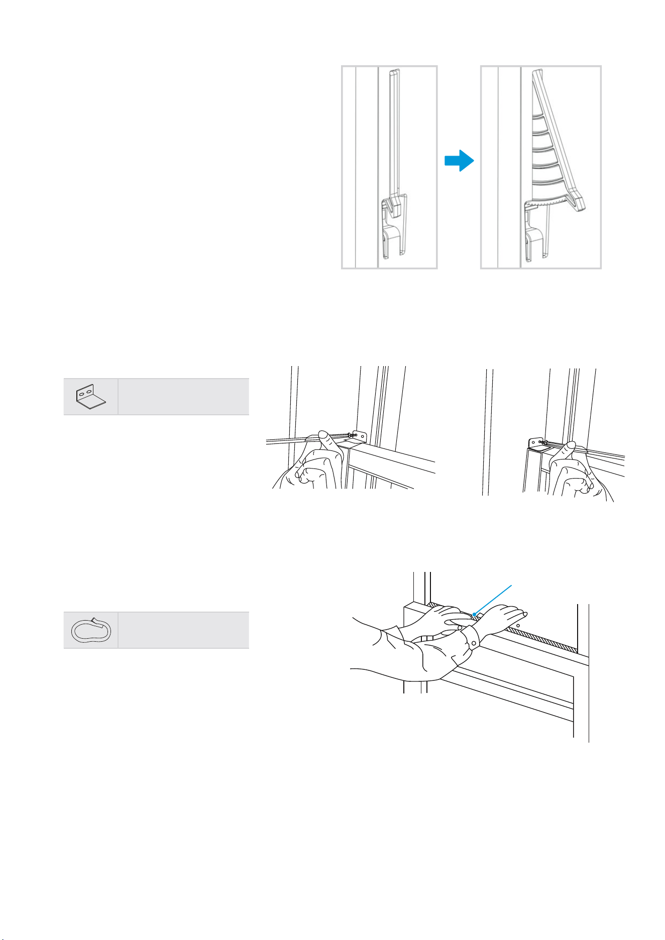
B. Move the Angled Support Arms toward the exterior
wall until the feet touch the wall. Place the level
on the bracket and adjust the Support Arms so
that it is level or tilted 1/4 bubble downward and
towards the outside. If exactly 1/4 bubble cannot
be achieved, set the angled support arms to the
closest setting so that a slight outward tilt exists.
Depending on the level
used, place at either
location below to
check level.
Here is what
1/4 bubble on
the level should
look like.
Fig. 5
WARNING
Maintain control of the bracket until installation is
complete.
2. Prepare the Window – Install Video Time 1:58
Lower sash must open sufficiently to allow a clear vertical opening of 13.75 inches. Side louvers and the rear of the
AC must have clear air space to allow enough airflow through the condenser for heat removal. The rear of the unit
must be outdoors, not inside a building or garage. Find the center of your window and lightly mark with a pencil.
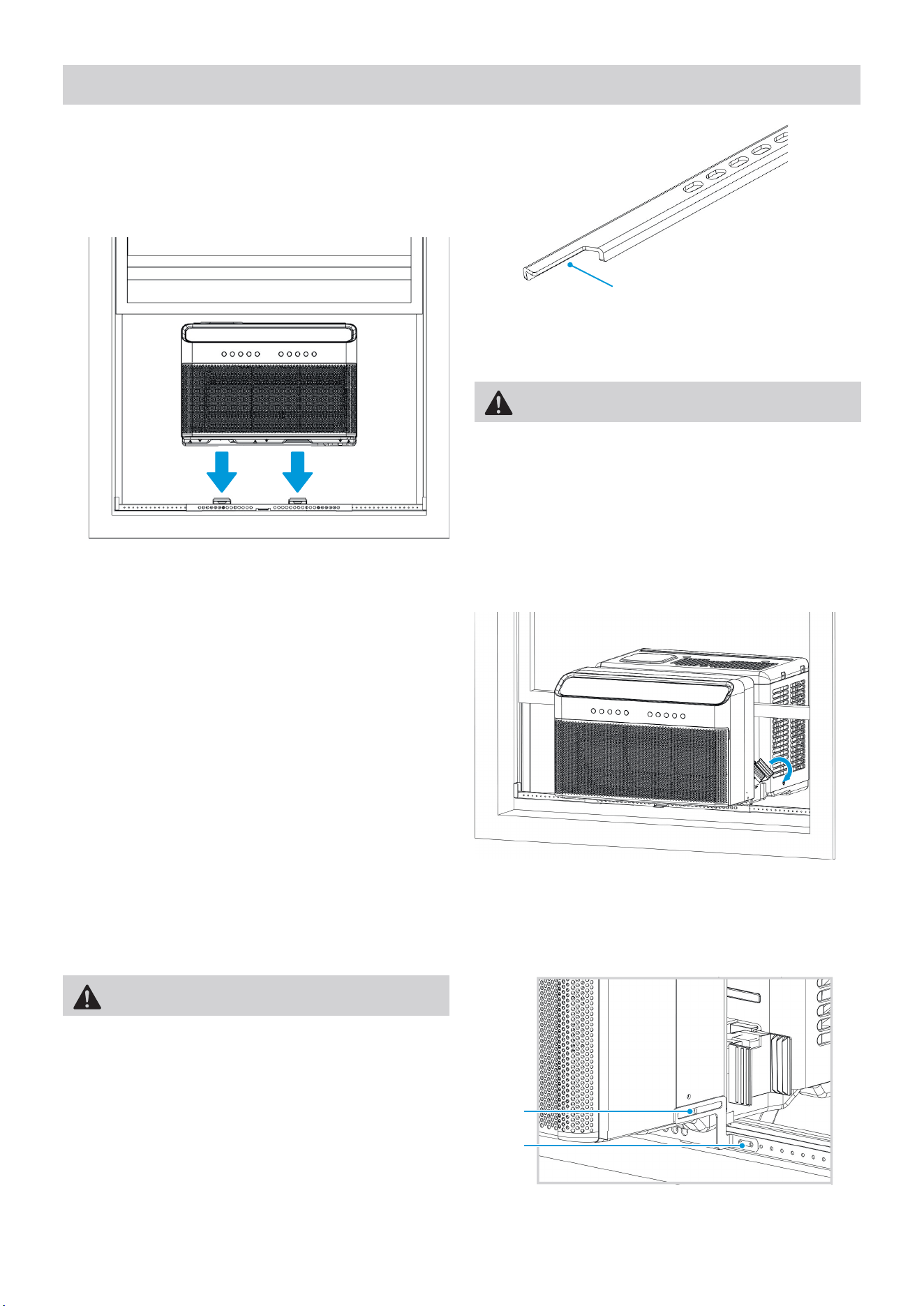
C. Insert the Main Support Pin through the holes in the
Main Support and Angled Support Arm. Match the
hole numbers on both Main Supports for alignment.
If further adjustment is needed, use alternate holes
where the Main Supports attach to the Horizontal
Bracket
Fig. 6
11
D. Check the level again and ensure the bracket feels
secure. After making any necessary adjustments,
insert the cotter pins into the Main Support Pins.
E. If necessary, cover the holes on the front of the bracket with the Bracket Sealing Foam.
Fig. 7
Cotter
Pin
Cover holes with
Bracket Sealing Foam
Cover holes with
Bracket Sealing Foam
Fig. 10
Fig. 9
1/2”
Type A
1/2”
Type A
1” Type A
(Flat Sill)
1” Type A
(Flat Sill)
Secure the bracket to the windowsill by drilling 1/8”
pilot holes and installing the 1/2” Type A screws as
shown in Fig. 9.
If your window has a lip, make sure the bracket is
placed as shown in Fig. 8.
If your window does not have a lipped sill, be sure to
drill 1/8” pilot holes and install the 1” Type A (Flat Sill)
screws as shown in Fig. 9 below.
Vinyl Lip
OUTSIDEINSIDE
Fig. 8
12
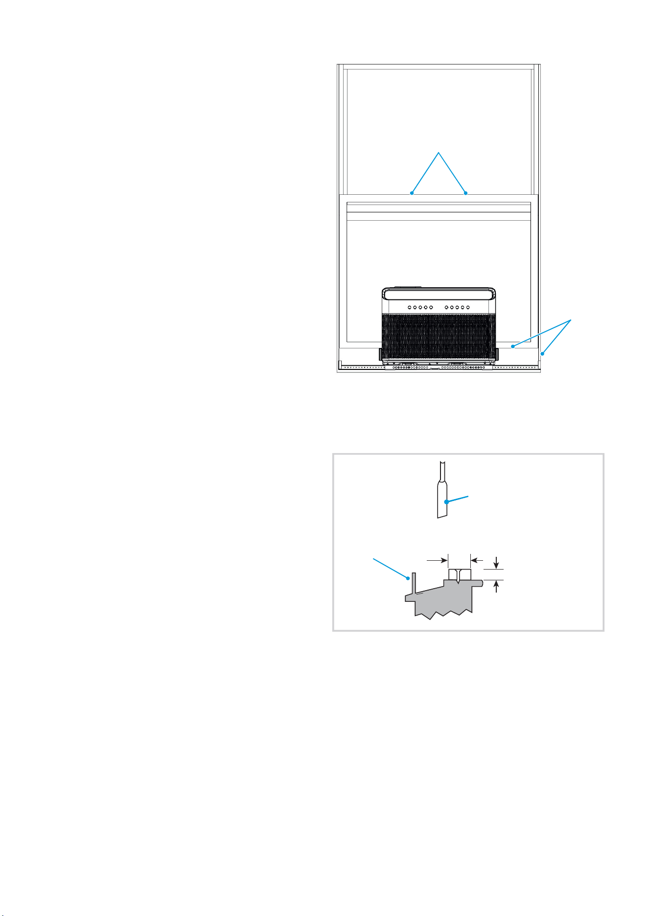
4. Install Air Conditioner – Install Video Time 4:36
A. Set the air conditioner on top of the support
bracket. Ensure the grooves on the bottom of the
air conditioner align with the Main Supports. Using
a level, check for proper tilt towards the outside.
B. Pull the window down into the slot to help
align the unit in the correct location. Keep the
window partially inserted into the slot to maintain
alignment during installation. Fold down both Side
Arm Hinges.
Fig. 13
WARNING
Do not leave the unit unattended during installation.
Fig. 12
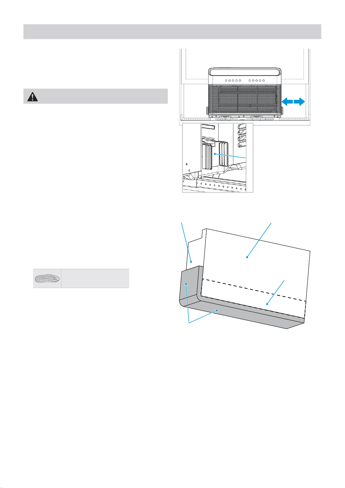
C. Next, you must install the Open Window Brackets
using the provided screws as shown.
Use the 1/2” Type B screw.
Use the 1/4” Type B screw.
Fig. 14
WARNING
Failing to install the Open Window Brackets could
cause injury or property damage.
This side faces indoors
Fig. 11
Openwindowbracketsareforfixingunitsandbrackets.
13
WARNING
Do not leave the unit unattended during installation.
5. Foam Installation – Install Video Time 5:33
A. Measure the distance between the Side Arm Hinge
and the closest part of the window frame in line
with the Side Arm. Add 1/4” to this distance and
cut the Side Arm Foam to length.
Fig. 15
B. Apply Window Sealing Foam to the Side Arm Foam
as shown. Note that the Window Sealing Foam
attaches to the side next to the air conditioner.
If your window does not have a lipped sill, apply
the Additional Side Arm Foam as shown with the
dotted line.
Additional Side Arm
Foam (Flat Sill only)
Window Sealing Foam
Side Arm FoamAir Conditioner Side
Fig. 16
Window Sealing Foam
14
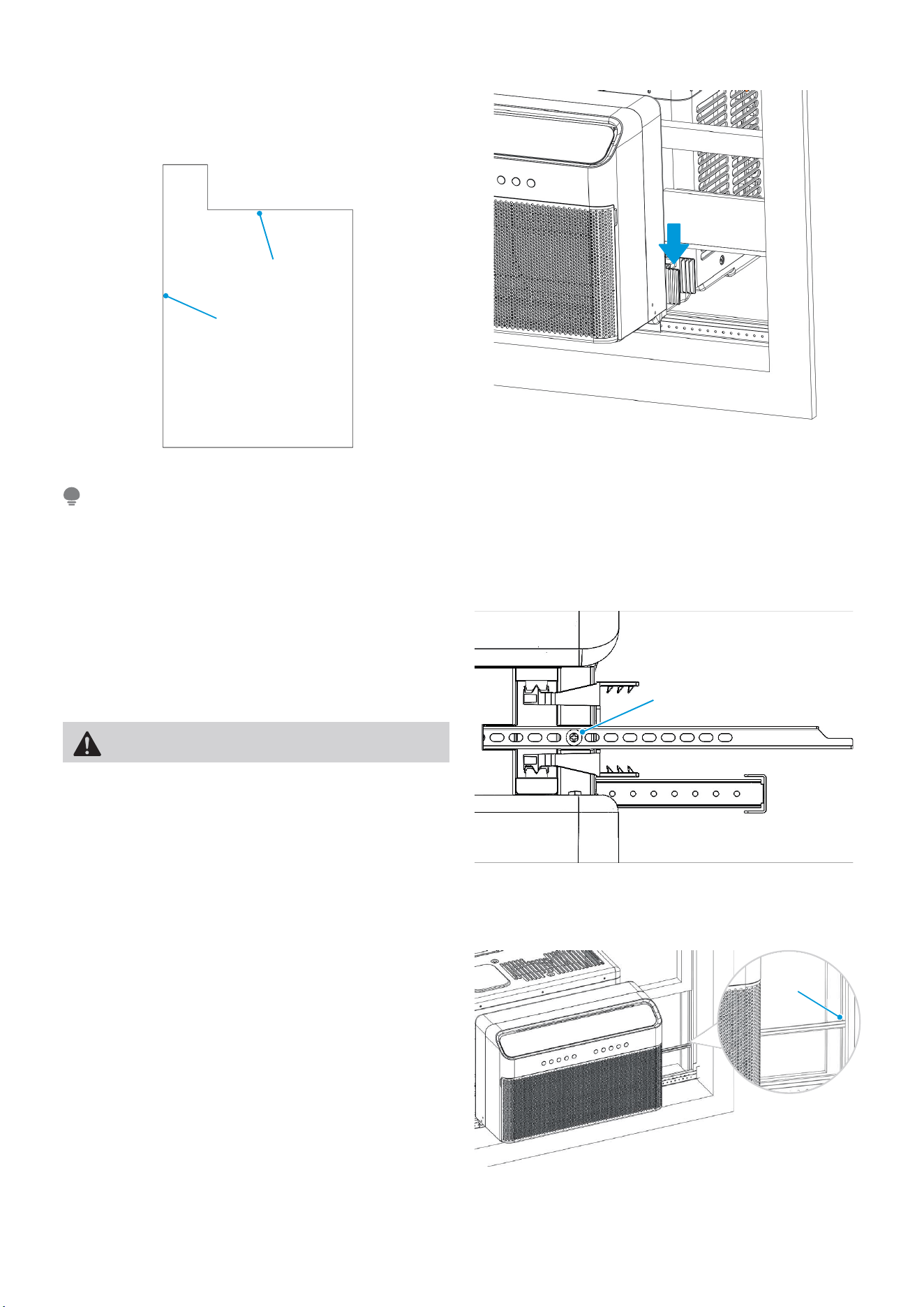
C. Insert Side Arm Foam into Side Arm Hinge until
the topfrontoftheSideArmisflush with the top
of the hinge.
Fig. 17
Fig. 18
Top
Front
Repeat the side arm foam installation steps on the other side of the unit as well.
NOTE
D. The Anti-Tip Brackets (located in the U channel)
must be extended into the window track opening
(vertical track your window slides up and down
in) until they stop. Secure the brackets in place by
reusing the screw you just removed.
WARNING
You must extend the Anti-Tip Brackets into the
Window Track Opening. Failure to follow this warning
may cause serious injury.
Top view
The currently installed screw
must be re-used to secure
the Anti-tip bracket. Failing
to use this screw could
damage the air conditioner.
Top of Unit
Fig. 19
The image shows how the Anti-Tip Bracket is to be
installed in the window track. Note the Side Arm
Foam was removed for illustration purposes only.
Fig. 20
15
E. Install a strip of Window Sealing Foam to the
bottom of your lower sash sealing any small gaps
between the window and air conditioner. Then
close the window and check for gaps. Fill any gaps
with the included foam as needed.
F. Extend the Integrated Window Locks (located in
the U channel) until they contact the window.
G. (Optional) To secure the lower sash in place,
attach the Window Sash Lock with 1/2” Type A
screws as shown.
H. Cut window sash foam and insert it in the space
between the upper and lower sashes.
Fig. 21
Fig. 22
or
Window Sash Foam
Window Sash Lock
Fig. 23
FOAM SEAL
FOAM SEAL
16
Final Check: Review the installation and check for any
gaps or openings to the outdoor air. Cover these gaps
with the provided foam ensuring no outdoor air leaks
inside. See image for areas to check for gaps.
Check
for Gaps
Check for Gaps
Fig. 24
IF AC IS BLOCKED BY STORM WINDOW
Add wood as shown, or remove storm window before
air conditioner is installed.
If storm window frame must remain, be sure the
drain holes or slots are not caulked or painted shut.
Accumulated rain water or condensation must be
allowed to drain out.
You must secure the support bracket to the added
wood piece using the provided 1” Type A Screws.
Refer to the Open Window Bracket installation step.
SASH
OUTSIDE INSIDE
1-1/2" min
(38 mm)
Board thickness as
required, for proper
pitch to rear, along
entire sill. Fasten
with nails or screws.
Storm window
frame or other
obstruction.
Fig. 25
Storm window
frame or other
obstruction.
Board thickness as
required, for
proper
pitch to rear, along
entire sill. Fasten
with nails or
screws.
1-1/2” min
(38 mm)
INSIDE
SASH
OUTSIDE
17
OPERATION INSTRUCTIONS
Normal Sounds
Sound Performance
The following table shows the sound performance data for these window air conditioners.
Pleaseuseyourspecificmodelnumbertoreferencethecorrectsoundpowernumberinthetable.
*)A(Bd ,rewoP dnuoSrebmuN ledoM
24MAW08V1QWT/MAW08V1QWT-T
24TWQ1V01WAM
24TWQ1V21WAM
* per ISO 3744 at low fan speed
All the illustrations in this manual are for explanation purpose only. The actual installation may vary.
NOTE
Gurgle/Hiss
Gurgling or hissing noises may be heard
duetorefrigerantflowingthrough
evaporator during normal operation.
Sound of Rushing Air
In front of the unit, you may
hear the sound of rushing air
being moved by the fan.
High Pitched Chatter
Highefficiencycompressors
may have a high pitched
sound during cooling cycle.
Vibration
Unit may vibrate and make
noise because of poor wall
or window construction or
incorrect installation.
Trickling Sound
Droplets of water hitting
condenser during normal
operation may cause a
trickling sound.
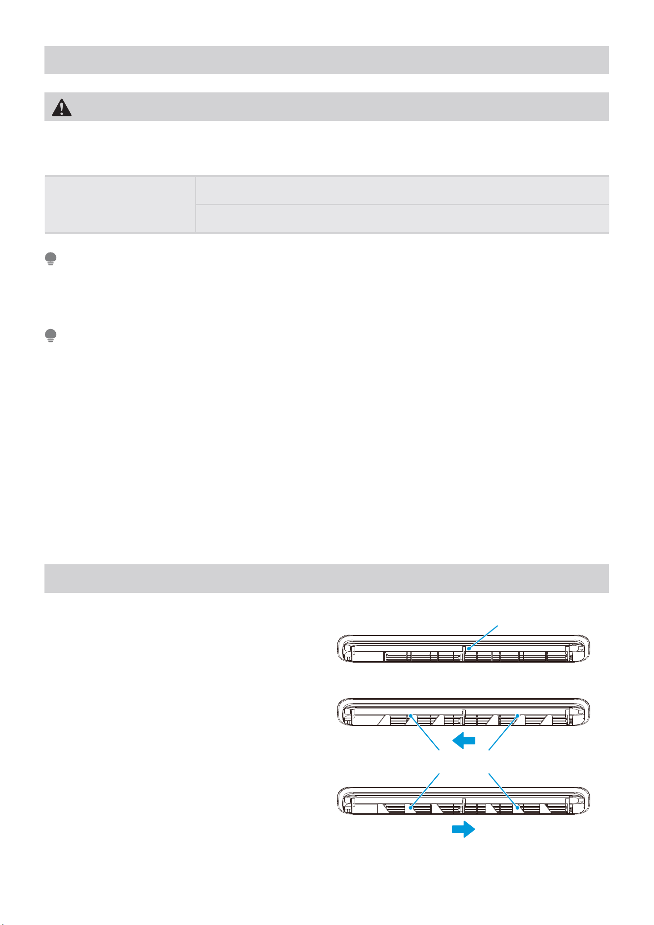
Move the louvers from side to side until the desired
left/right direction is obtained.
18
Air Conditioner Operation
Air Directional Louvers
WARNING
Toreducetheriskoffire,electricalshock,orinjurytopeopleorproperty,readtheSAFETYPRECAUTIONS
before operating this appliance.
Cooling Operation
Outdoor temp.: 64°F ~ 109°F / 18°C ~ 43°C
Indoor temp.: 60°F ~ 90°F / 16°C ~ 32°C
• The relative humidity of the room should be less than 80%. If the unit is used in a condition with a relative
humidity over 80%, there will be condensed water on the surface of the unit.
• Performance may be reduced outside of these operating temperatures.
NOTE
Always wait 3 minutes when turning the unit off and then on again, or when changing from cool to fan and back
to cool. This prevents damage from occurring to the compressor.
NOTE
To begin operating the air conditioner, follow these steps:
1. Plug in the air conditioner (be sure to follow the power cord instructions).
2. Turn the power on to the air conditioner, using the ON/OFF button.
3. Set the thermostat to the coldest temperature setting.
4. Select the Cool mode setting.
5. Adjustthelouverforcomfortableairflow(seeAirDirectionalLouvers).
6. Oncetheroomhascooled,adjustthethermostattothesettingyoufindmostcomfortable.
7. Makesuretheairflowinsideandoutsideisnotobstructedbyanything.
Thelouverswillallowyoutodirecttheairflowupor
down and left or right throughout the room as needed.
Use the SWING button until the desired up/down
direction is obtained.
Use SWING button for up/down direction
Adjust louvers for left/right direction
Air Direction
19
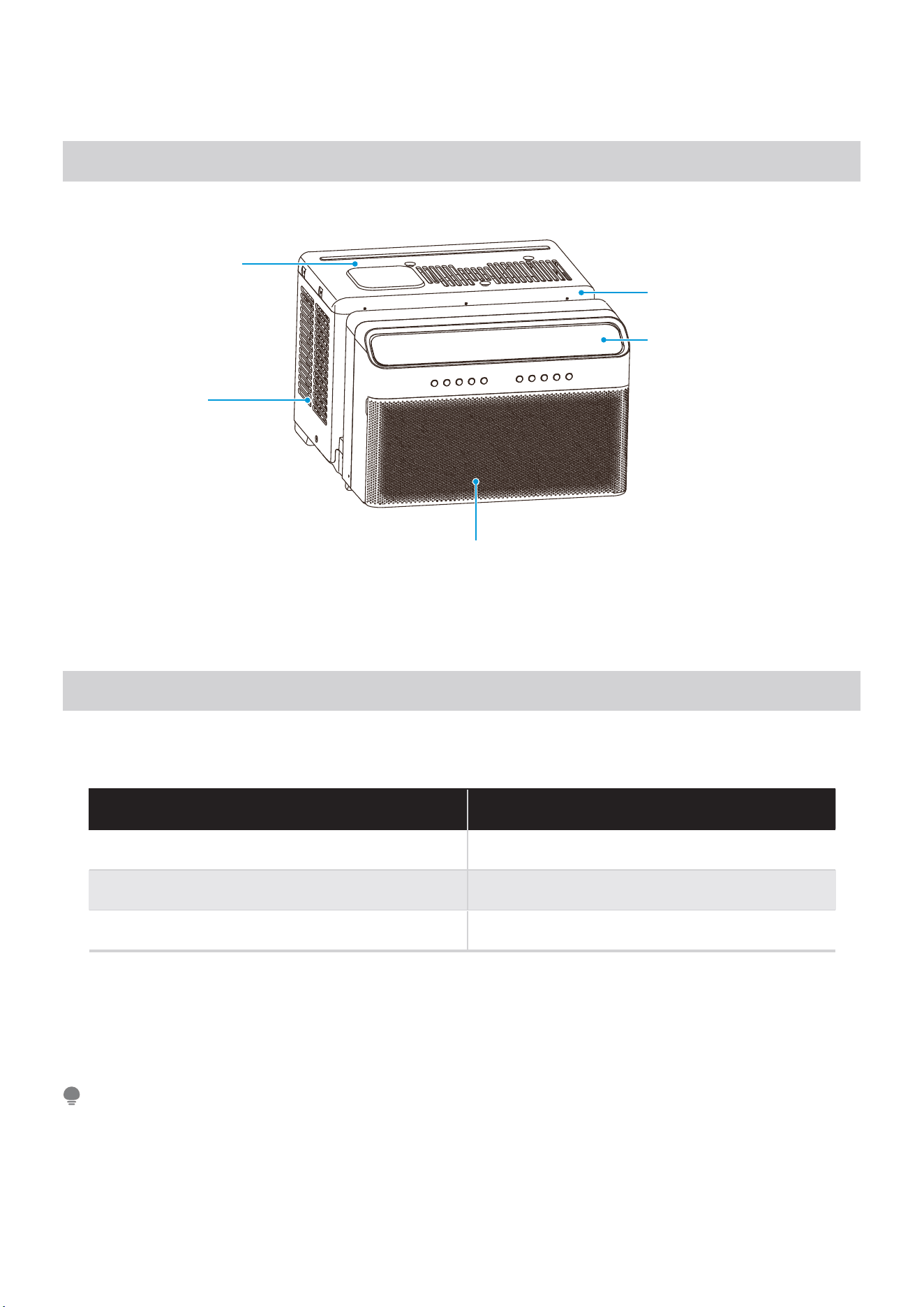
Air Conditioner Features
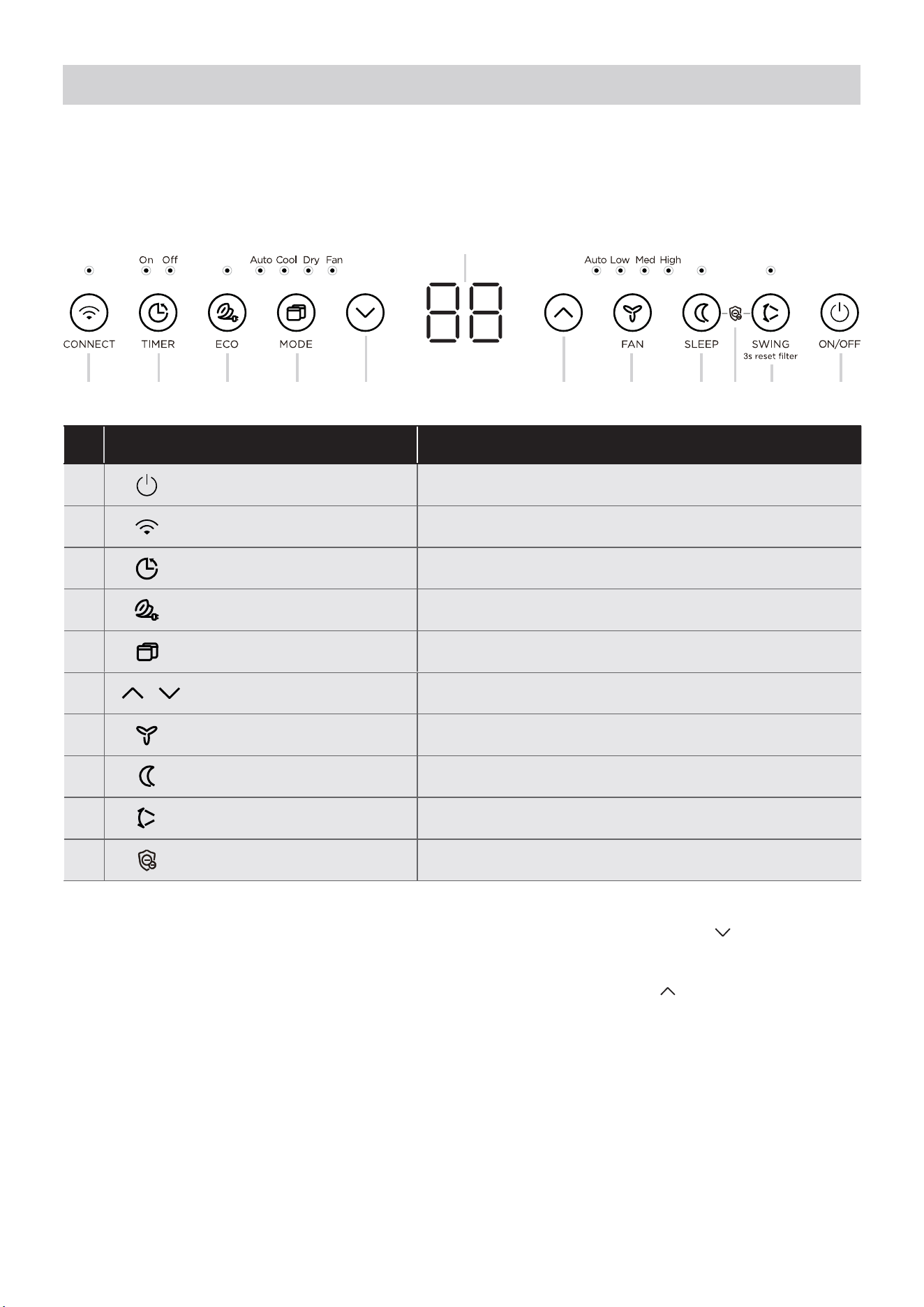
ELECTRONIC CONTROL OPERATING INSTRUCTIONS
Before you begin, thoroughly familiarize yourself with the control panel as shown below and all its functions,
then follow the symbol for the functions you desire. The unit can be controlled by the control panel, remote
control, smartphone app or voice control.
1. ON/OFF Button
Press ON/OFF button to turn unit on or off.
2. CONNECT Button
When connecting your air conditioner to WiFi, press
the CONNECT button for 3 seconds to initiate the
WiFi connection mode. The display shows ‘AP’ to
indicate the unit is in the WiFi connection mode. Refer
to the WiFi section for further instructions.
If connection (router) is successful within 8 minutes,
the unit will exit WiFi connection mode automatically
and the CONNECT indicator illuminates.
If connection failed within 8 minutes, the unit
exits WiFi connection mode automatically and the
CONNECT indicator does not illuminate.
After WiFi connection is successful, you can press
and hold CONNECT and DOWN (
) buttons at the
same time for 3 seconds to turn off WiFi function
and the LED DISPLAY shows ‘OF’ for 3 seconds,
press CONNECT and UP ( ) buttons at the same
time to turn on WiFi function and the LED DISPLAY
shows ‘On’ for 3 seconds.
3. Timer Button: Auto Start/Stop Feature
TIMER Button
• The TlMER button allows you to enable the AUTO OFF
feature and the AUTO ON feature, which allowyou to
set a desired time for the unit to turn off or on
automatically.
2 3 4 5 7 8 9 16 6 10
Description
1 .ffo ro no tinu nrut ot sserP •FFO / NO
2 Connect Function • Press to initiate smart connection mode.
3 Timer Feature • Press to turn unit Auto Start/Stop.
4 Energy Saver Feature
• Press to initiate this feature, which will maintain comfort
and save energy.
5 Mode Fuctions
• Press to choose operating mode in a sequence that goes
from Auto, Cool, Dry and Fan.
6
Up/Down
Butto • Press to change temperature setting.
7 Fan Speed
• Press to select the Fan Speed in four steps - Auto, Low,
Med or High.
8 Sleep Function • Press to initiate the sleep mode.
9 Swing / Check Filter Feature
• Press to initiate the auto swing feature.
• Pressfor3sectoturnoffthecleaningfilterreminder.
10
MShield Feature
(For some models)
LED Display
• Press to start and stop the Ionizer.

20
6. UP/DOWN Button
Press UP ( ) or DOWN ( ) button to change
temperature setting.
7. FAN SPEED Button
Press Fan button to select the Fan Speed in four
steps - Auto, Low, Med or High. Each time the
button is pressed, the fan speed mode is shifted.
8. SLEEP Button
Press Sleep button to initiate the sleep mode. In
this mode the selected temperature will increase
(in cooling mode) by 2°F (1°C) 30 minutes after the
mode is selected.
This new temperature will be maintained for 7 hours
before it returns to the originally selected temperature.
This ends the Sleep mode and the unit will continue
to operate as originally programmed. The Sleep
mode program can be cancelled at any time during
operation by pressing the Sleep button again.
9. Swing Button
Use the SWING button to initiate the auto swing
feature for the outlet louver. When the auto swing is
on, pressing the SWING button can stop the louver at
the desired angle.
• While the unit is running, press the TIMER button
once to enable the AUTO OFF feature.
• Press the UP and DOWN buttons to choose the
desired time, in hours, to turn the unit off.
To operate the AUTO OFF Feature
• When the unit is powered off, press the TIMER
button once to enable the AUTO ON feature.
Press theUP and DOWN buttons to choose the
desired time, in hours, to turn the unit on.
To operate the AUTO ON Feature
• Turning the unit ON or OFF at any time or
adjusting the timer setting to 0.0 will cancel the
Auto Start/Stop timed program.
To cancel timer operation, press and hold the timer
button for 2 seconds until the beep/buzzer is heard.
NOTE
4. EC0 Button
ECO mode on by default, pressing it turns it off.
This function is available on COOL, DRY, and AUTO
(only AUTO-COOLING and AUTO-FAN) modes.
The fan will continue to run for 3 minutes after the
compressor shuts off.
The fan then cycles on for 2 minutes at 10 minute
intervals until the room temperature is above the set
temperature, at which time the compressor turns back
on and Cooling Starts.
5. MODE Button
• To choose the operating mode, press the MODE
button. Each time you press the button, a mode is
selected in a sequence that goes from Auto, Cool,
Dry and Fan. The indicator light beside the button
will be illuminated and remain on once that mode
is selected.
• When the unit is turned off and back on via the
power button, the unit will automatically switch
on the Energy Saver Function for the following
modes: Cool, Dry, Auto.
To operate on AUTO feature:
• When you set the air conditioner to AUTO mode,
it will automatically select cooling or fan only
operation, depending on what temperature you
have selected and the current room temperature.
• The air conditioner will automatically control the
room temperature according to the temperature
you’ve set.
• In this mode, the fan speed cannot be adjusted
and is automatically controlled based on the
temperature setting and room temperature.
To operate on COOL mode:
• Choose Cool Mode to set the cooling function.
Use the UP (
) or DOWN ( ) buttons to choose
the desired temperature. When Cool Mode is
selected, the fan speed can be adjusted by
pressing the fan button.
To operate on DRY mode:
• In this mode, the air conditioner will generally
operateasadehumidifier.Sincetheconditioned
space is a closed or sealed area, some degree of
cooling will continue. On Dry mode, the fan speed
is not adjustable.
To operate on FAN mode:
• Use this function only when cooling is not desired,
such as for room air circulation. You can choose
any fan speed you prefer.
• In Fan Only mode, the temperature can not be
adjusted and the display will show the actual
room temperature, not the set temperature as in
the cooling mode.

21
Check Filter Feature:
The Check Filter feature is a reminder to clean the
airfi lter for a more efficient operation. The light
above the button will illuminate after 250 hours of
operation. After cleaning thefilter, press the SWING
button for 3 seconds to reset the Check Filter feature
turning the light off.
10. MShield Feature
Press SWING and SLEEP at the same time for 3
seconds to initiate the MShield feature. The Mshield
light will illuminate while enabled. To disable Mshield,
press SWING and SLEEP again for 3 seconds until the
Mshield light turns off.
Displays
LED Display:
Shows the set temperature in “°C” or “°F” and
the Auto-timer settings. While on Fan Only mode,
it shows the room temperature. If the room
temperature is too high or low, it will display “ HI” or
“ LO”.
To change between °F and °C, press and hold the UP
( ) and DOWN ( ) buttons at the same time for 3
seconds.
Error codes:
The unit may stop operation due to a malfunction
with the unit. If this occurs, an error code may
appear on the display like below.
Wait 10 minutes as the problem may resolve itself.
If not, disconnect the power, then connect it again.
Turn the unit on.
If the problem persists, disconnect the power and
contact customer service.
Error code appears and begins with the letters as the
following in the window display of indoor unit:
EH(xx), EL(xx), EC(xx) , PH(xx), PL(xx), PC(xx).
If the unit turns off unexpectedly due to the power
being cut, it will automatically restart with the
previous function setting when the power resumes.
NOTE
(For some models)
22
REMOTE CONTROL AND APP INSTRUCTIONS
Handling the Remote Control
Inserting and Replacing Batteries
RemoteControlSpecifications
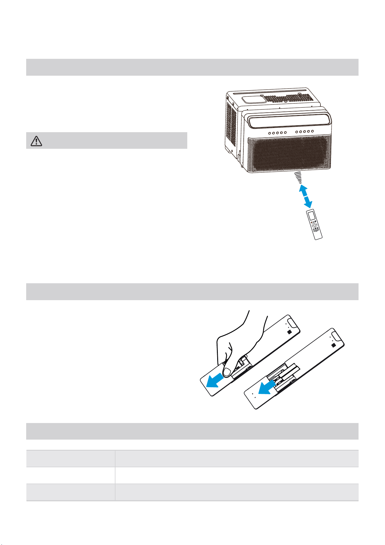
Location of the remote control
Use the remote control within a distance of 26 ft. (8m)
from the air conditioner, pointing it towards the unit.
The unit will beep when it receives a signal.
26 ft (8 meters)
CAUTION
• The air conditioner will not operate if curtains,
doors or other materials block the signals from the
remote control to the unit.
• Prevent any liquid from spilling onto the remote
control. Do not expose the remote control to
direct sunlight or heat.
• If the infrared signal receiver on the indoor unit is
exposed to direct sunlight, the air conditioner may
not function properly. Use curtains to prevent the
sunlight from falling on the receiver.
• If other electrical appliances react to the remote
control, either move these appliances or consult
your local dealer.
Your air conditioning unit may come with two
batteries (some units). Put the batteries in the remote
control before use.
1. Slide the back cover from the remote control
downward, exposing the battery compartment.
2. Insert the batteries, paying attention to match
up the (+) and (-) ends of the batteries with the
symbols inside the battery compartment.
3. Slide the battery cover back into place.
Rated Voltage 3.0V (Dry batteries R03/LR03x2)
Signal Receiving Range 26 ft (8 m)
Environment -5 °C ~ 60 °C (23°F ~ 140°F)
23
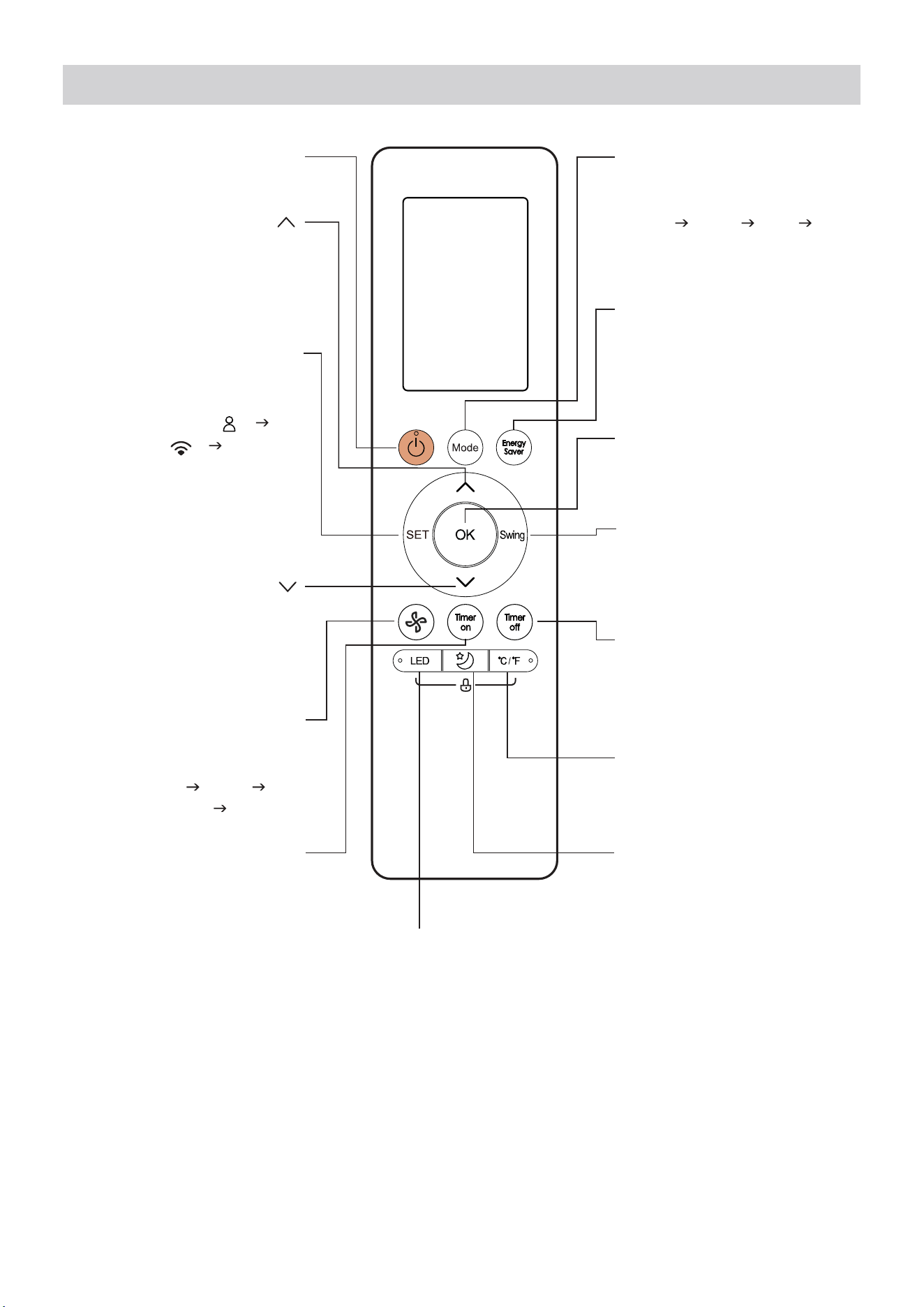
Function Buttons
TIMER OFF
Sets timer to turn unit off
(see How to Use Basic
Functions for instructions).
FAN SPEED
Switches the fan
speed as follows:
Auto Low
Medium High ...
SLEEP
Saves energy during
sleeping hours.
SWING
Starts and stops the
horizontal louver
movement.
ON/OFF
Turns the unit on or off.
Turn the unit’s LED display and
control panel beeps on or off.
LED
MODE
Switches the operating
modes as follows:
Auto Cool Dry Fan
TIMER ON
OK
Press to send the desired
settings to the AC unit.
TEMP
Decreases temperature
in 1°F (1°C) increments.
Min. temperature is
60°F (16°C).
TEMP
Increases temperate in
1°F (1°C) increments.
Max. temperature is
86°F (30°C).
Sets timer to turn
unit on (see How
to Use Basic
Functions for
instructions).
SET
Scrolls through operation
functions as follows:
Comfort Sense (
)
The selected symbol will
flash on the display area,
press the OK button to
confirm.
AP mode (
) ...
°C/°F
Change the temperature
units between °C and °F.
ENERGY SAVER
Press this button to toggle
energy saver mode.
24
LOW
MED
HIGH
AUTO
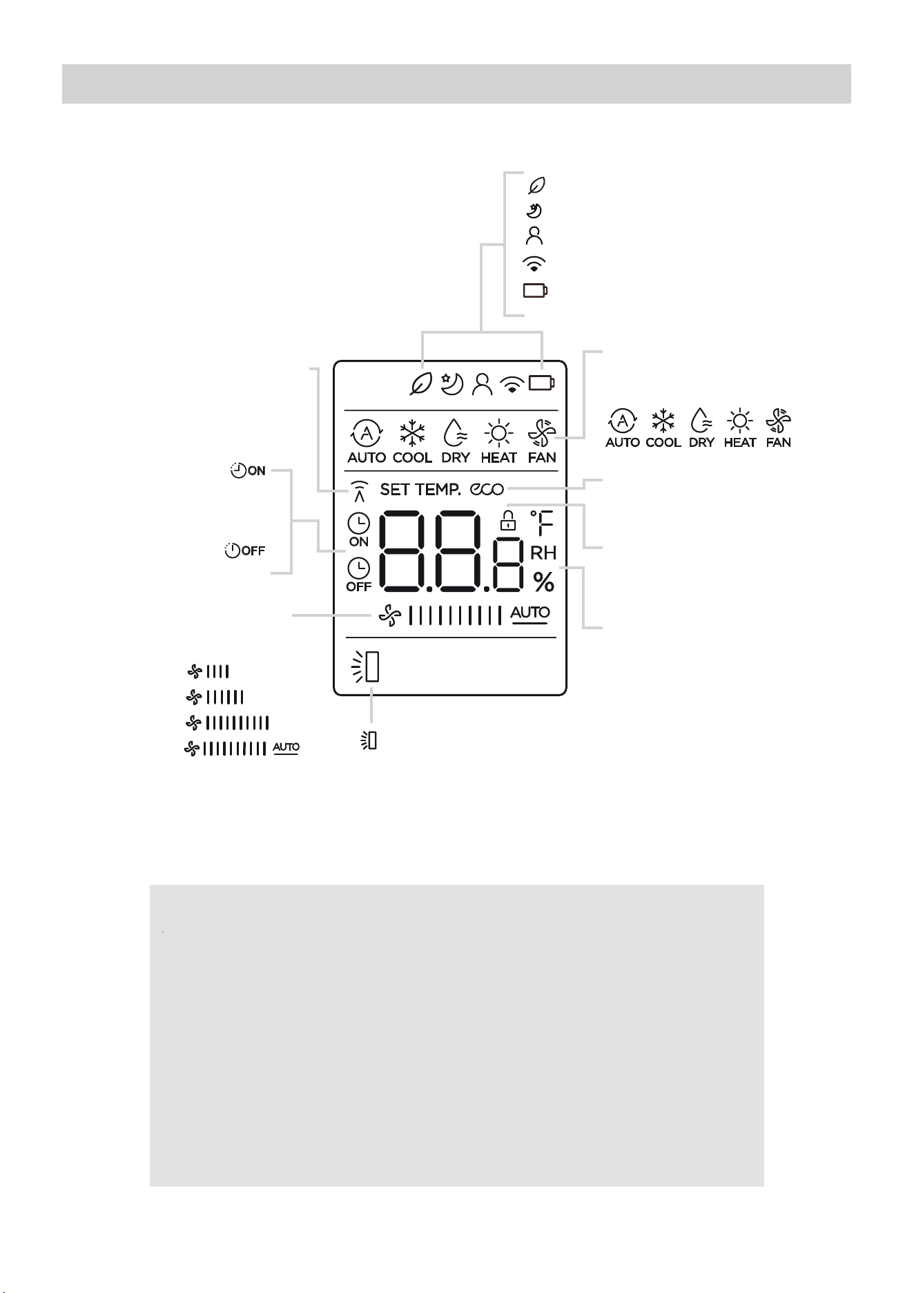
Remote Screen Indicators
Transmission Indicator
FAN SPEED display
TIMER ON
display
TIMER OFF
display
Lights up when remote sends
signal to indoor unit.
Displays selected fan speed:
This fan speed can not be
adjusted in AUTO or DRY mode.
Sleep mode display
MShield feature display
I Sense feature display
Wireless control feature display
Lowbatterydetectiondisplay(Ifflashes)
Information is displayed when the remote control is powered on.
MODE display
ECO display
Horizontal louver
LOCK display
Temperature/Timer/ Fan
speed display
Displays the current mode,
including:
Not available for this unit
auto swing display
Displays when LOCK feature is
activated.
Displays the set temperature by
default, or fan speed or timer
setting when using TIMER ON/
OFF functions.
• Temperature range: 16-30°C /
60-86°F
• Timer setting range: 0-24
hours
This display is blank when
operating in FAN mode.
Supplier's Declaration of Conformity
47 CFR § 2.1077 Compliance Information
Unique Identifier: Midea RG10G2(B2)/BGEFU1
Responsible Party U.S. Contact Information
Midea America Corporation
300 Kimball Dr
Parsippany NJ
07054
This device complies with Part 15 of the FCC Rules. Operation is subject to the
following two conditions: (1) This device may not cause harmful interference, and
(2) this device must accept any interference received, including interference that
may cause undesired operation.
Telephone number or internet contact information: Midea.com/us
FCC Compliance Statement ( products subject to Part 15)
25
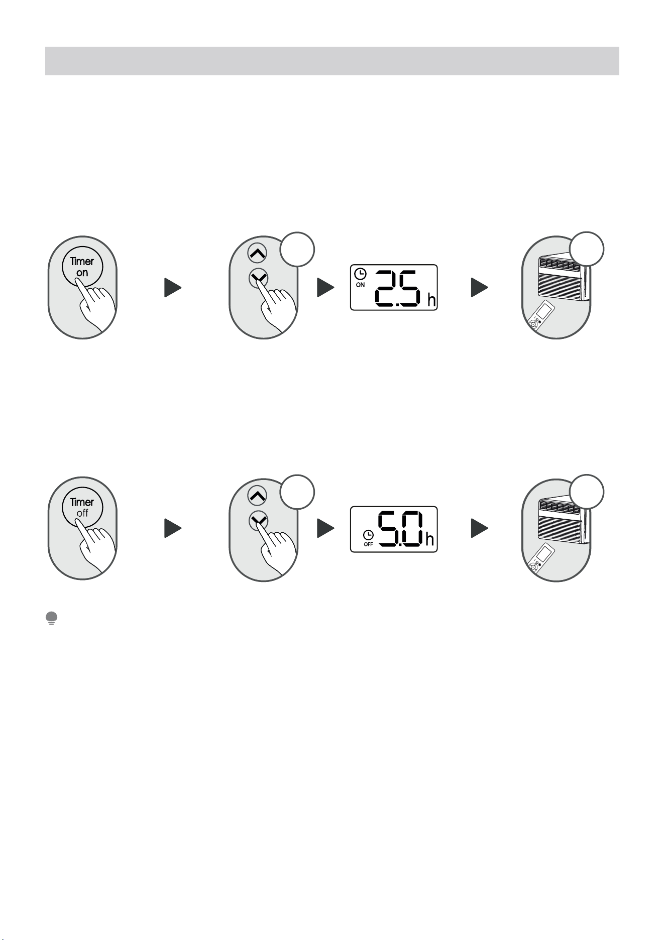
Setting the TIMER
TIMER ON/OFF
TIMER ON SETTING
TIMER OFF SETTING
Set the amount of time after which the unit will automatically turn on/off.
Press TIMER ON button to
initiate the ON time
sequence.
Press TIMER OFF button to
initiate the OFF time
sequence.
Press up or down button for
multiple times to set the desired
time to turn on the unit.
Press up or down button for
multiple times to set the desired
time to turn off the unit.
Point remote to unit and wait
1sec, the TIMER ON will be
activated.
Point remote to unit and wait
1sec, the TIMER OFF will be
activated.
1secx5
1secx10
1. When setting the TIMER ON or TIMER OFF, the time will increase by 30 minutes increments with each press,
up to 10 hours. After 10 hours and up to 24, it will increase in 1 hour increments. (For example, press 5 times
to get 2.5h, and press 10 times to get 5h,). The timer will revert to 0.0 after 24.
2. Cancel either function by setting its timer to 0.0h.
NOTE
26
Declaration of Conformity
SpecificationofWirelessModule
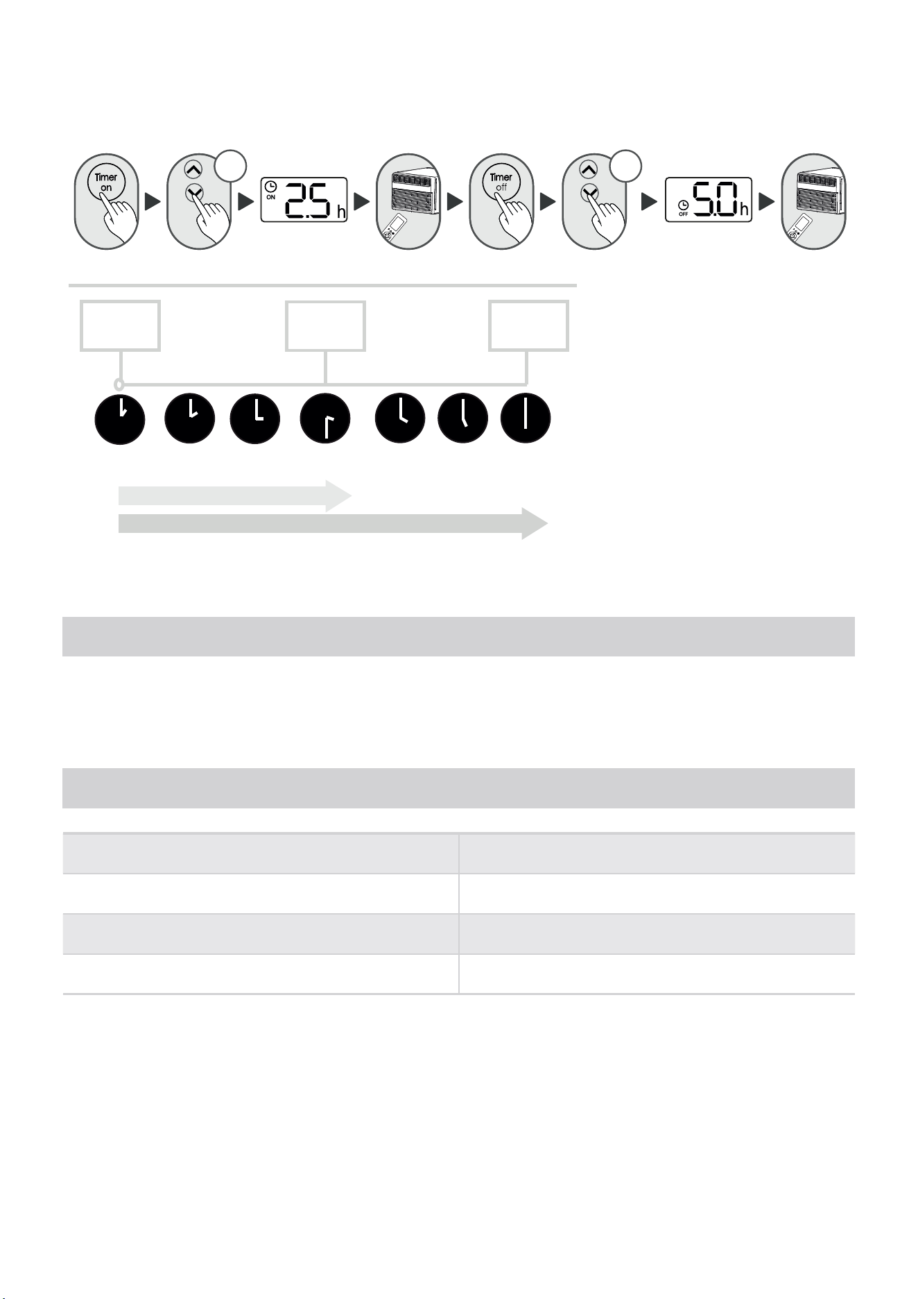
TIMER ON & OFF SETTING (example)
Keep in mind that the time periods you set for both functions refer to hours after the current time.
x5
Timer
starts
2.5 hours later
5 hours later
Current
time 1PM
2:00PM 3:00PM 3:30PM 4PM 5PM 6PM
Unit turns
ON
Unit turns
OFF
x10
We hereby declare that this AC is in compliance with the essential requirements and other relevant provisions of
Directive 1999/5/EC.
Model: US-SK109 Dimensions: 41 x 24 x 5 (mm)
Operation Temperature: 0°C ~ 45°C / 32°F ~ 113°F
Antenna Type: Printed PCB Antenna
Operation Humidity: 10% ~ 85%
Frequency: WLAN 2400-2483.5 MHz
Power Input: DC 5V/500 mA
Maximum Transmitted Power: <20 dBm Max
Example: If current timer is 1:00PM,
to set the timer as above steps,
the unit will turn on 2.5h later
(3:30PM) and turn o at 6:00PM.
27
1 How to use SmartHome App
Ensure that your mobile phone is connected to the wireless network. Bluetooth must be turned on.
The device must also be powered up.
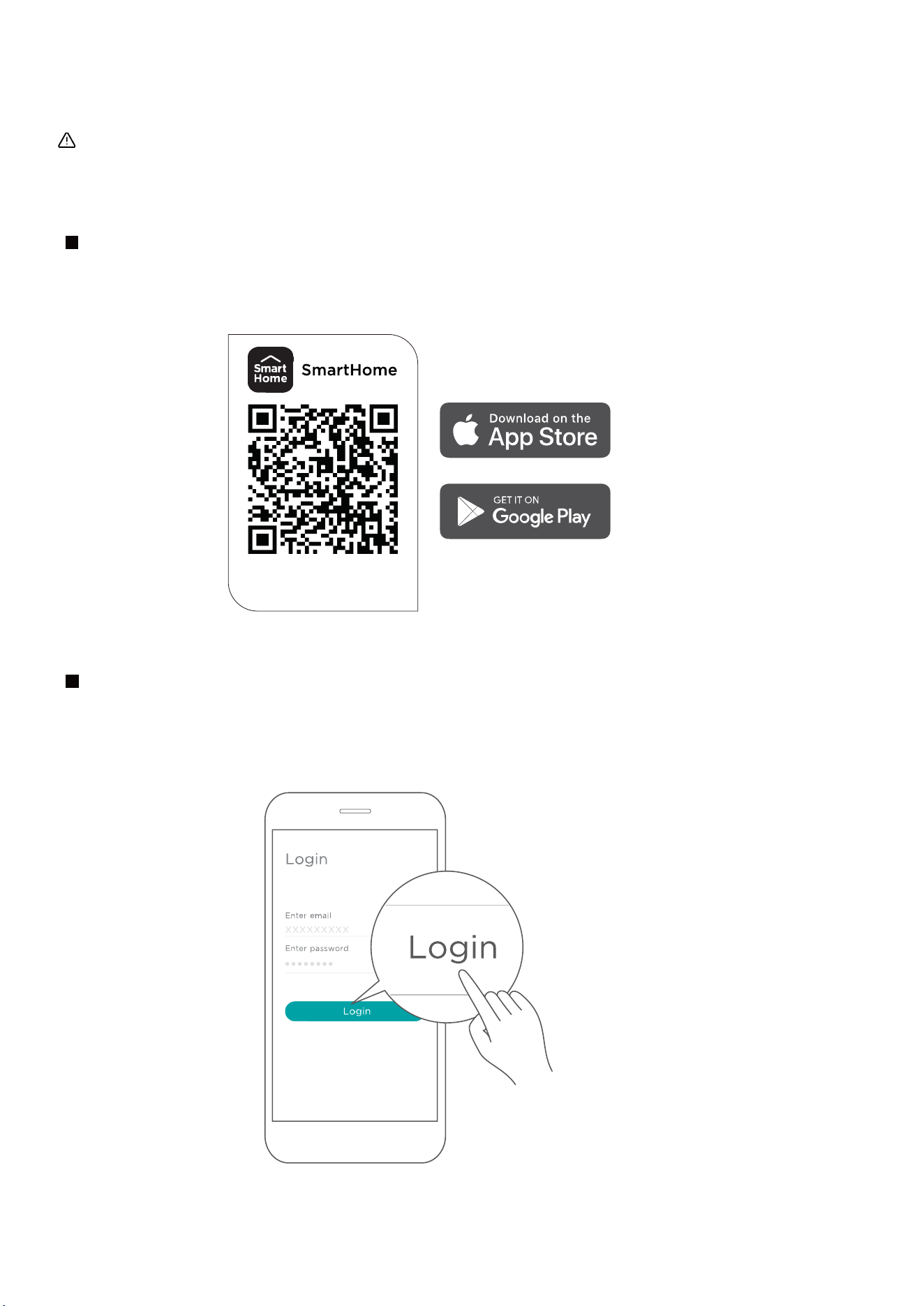
Scan the QR code below to download the SmartHome app from app store or search for it directly on
the Google Play Store or Apple's App Store.
Step 1: Download the SmartHome app
Open the SmartHome app. Log in directly if you have an existing SmartHome account or create a
new account. Alternatively, you can also use a 3rd party login platform.
Step 2: Log in
Download the app
& activate product
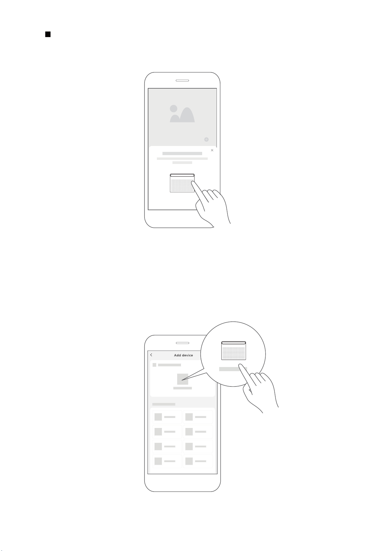
1) When you log in, you may see the message "Smart devices discovered nearby".
Tap to add your device.
2) If no such message appears, proceed as follows: Tap on "+" and select your device in the list of
nearby available devices.
If your device is not listed, please add your device manually, first selecting the device category e.g.
Window AC.
Step 3: Connecting the device
28
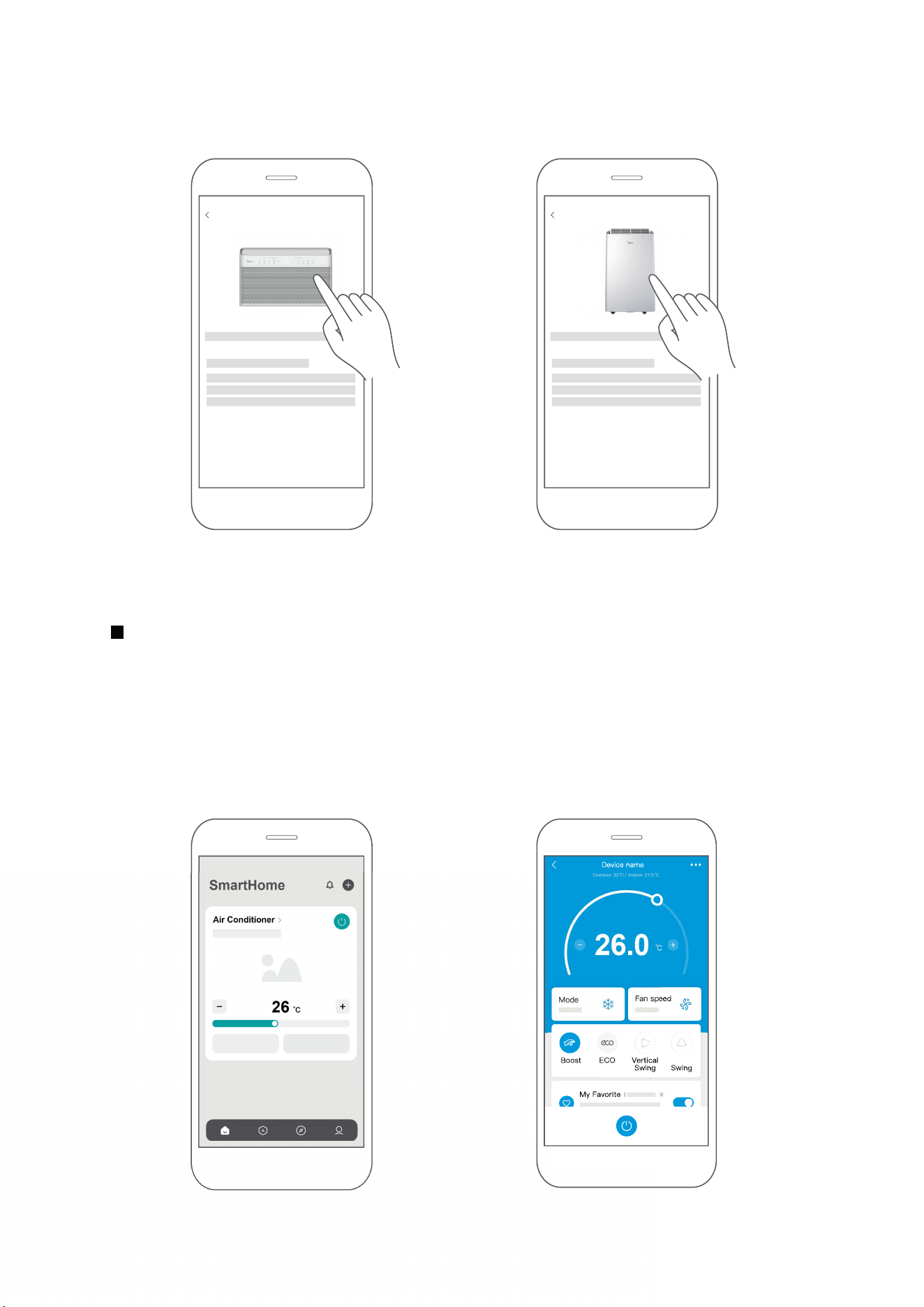
After pairing successfully, a card will be created for the device in the SmartHome app.
Shortcuts for basic functions will appear on the card such as changing the temperature or switching
the device on or o.
Tapping on the card, will reveal additional features and settings. The actual UI design may look
dierent from examples due to app updates.
Step 4: Controlling the device
Air Conditioner
26
SmartHome
26.0
Horizontal
Sleep Curve
3) Follow the steps in the app to connect your device to the wireless network. If your device fails to
connect, follow the additional instructions in the app.
Add device
For Window AC For Portable
AC
Add device
29
2
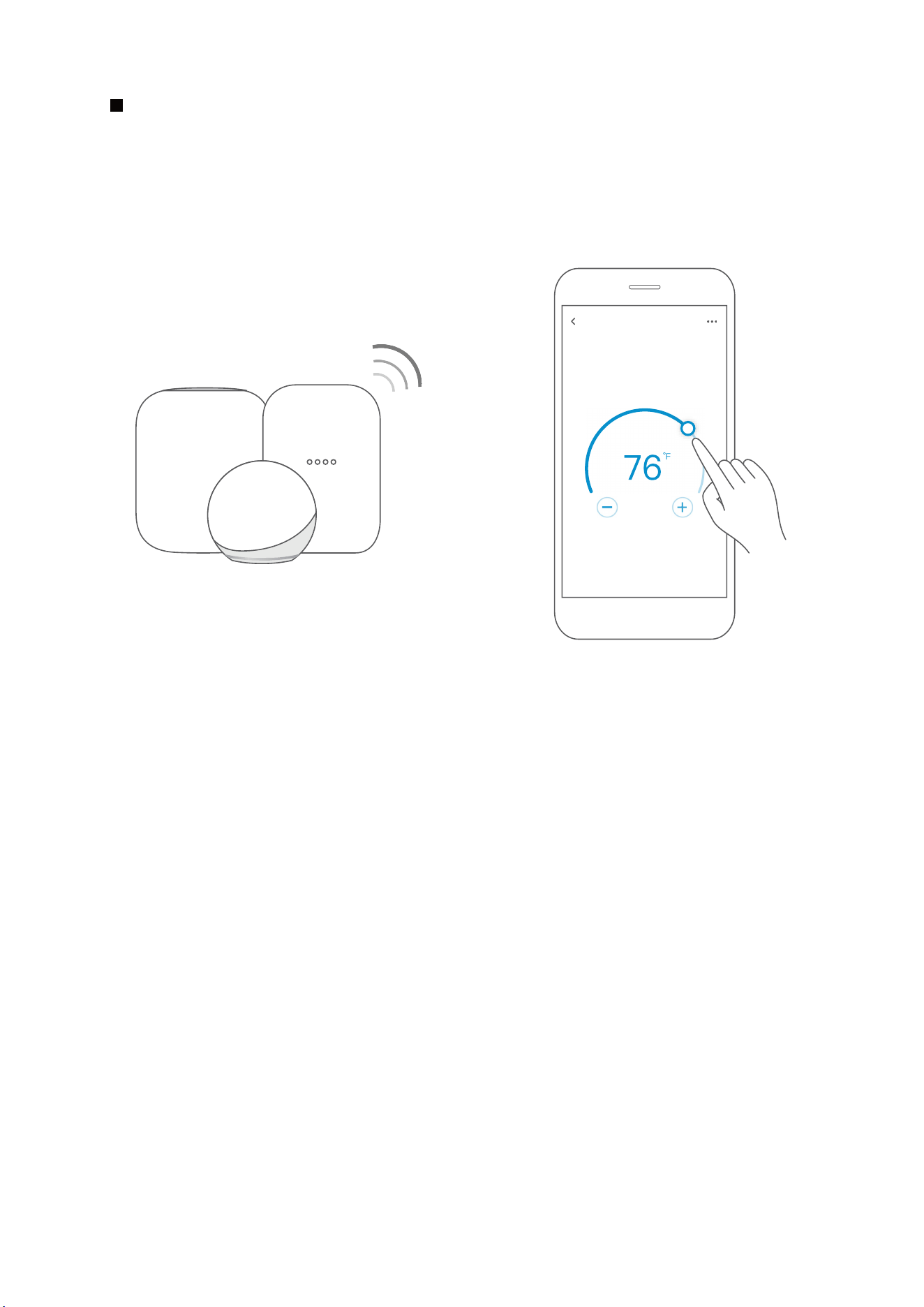
How to use Matter
Connect YourAir Conditioner through Matter
Make sure your mobile device is connected to your wireless router.
Wireless router should support and turn on IPv6. Please make sure your smartphone connect to 2.4G
but not 5G network.
Matter is a connectivity technology that unifies the smart home by allowing devices and ecosystems
(such as Alexa, Google Home and Apple Home) to speak the same language thus creating exciting
new features and use cases.
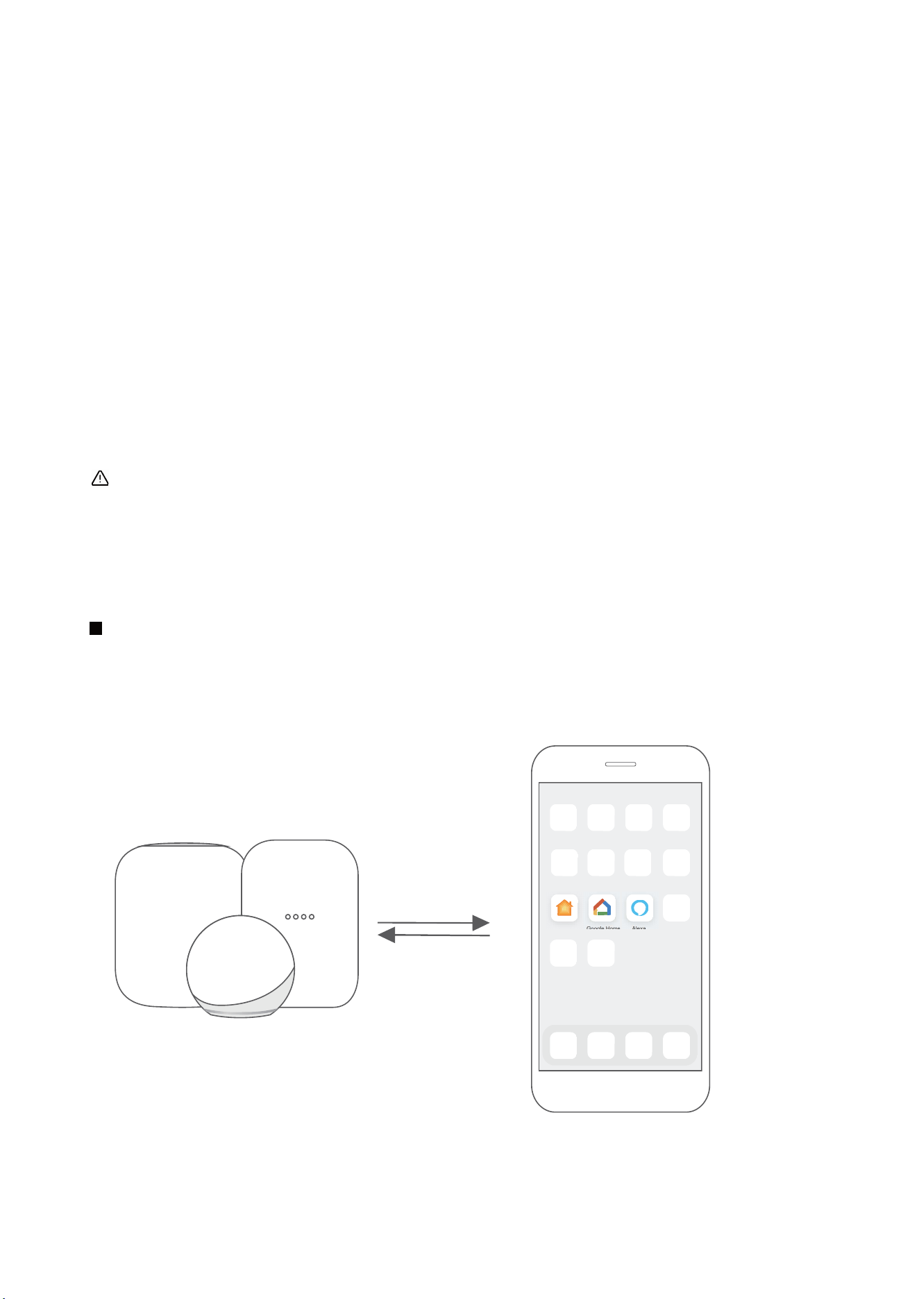
To use Matter, you will need at least one Matter enabled smart speaker from Amazon, Google or Apple,
and it's respective app.
-- If you have a Matter enabled smart speaker, please proceed to the "How to use Matter" instructions on
the following pages.
-- If you don't have a Matter enabled smart speaker, you won't be able to use Matter right now. However,
you can still achieve full functionality of the product by using our SmartHome app. To do this, proceed to
the "How to use SmartHome app" section back on page 1.
Step 1: Connect to smart speaker
Select your preferred ecosystem (Alexa, Google Home or Apple Home) and make sure you’ve got one
of their Matter enabled products (such as their smart speakers) connected to your wireless router.
Apple Home Google Home Alexa
30
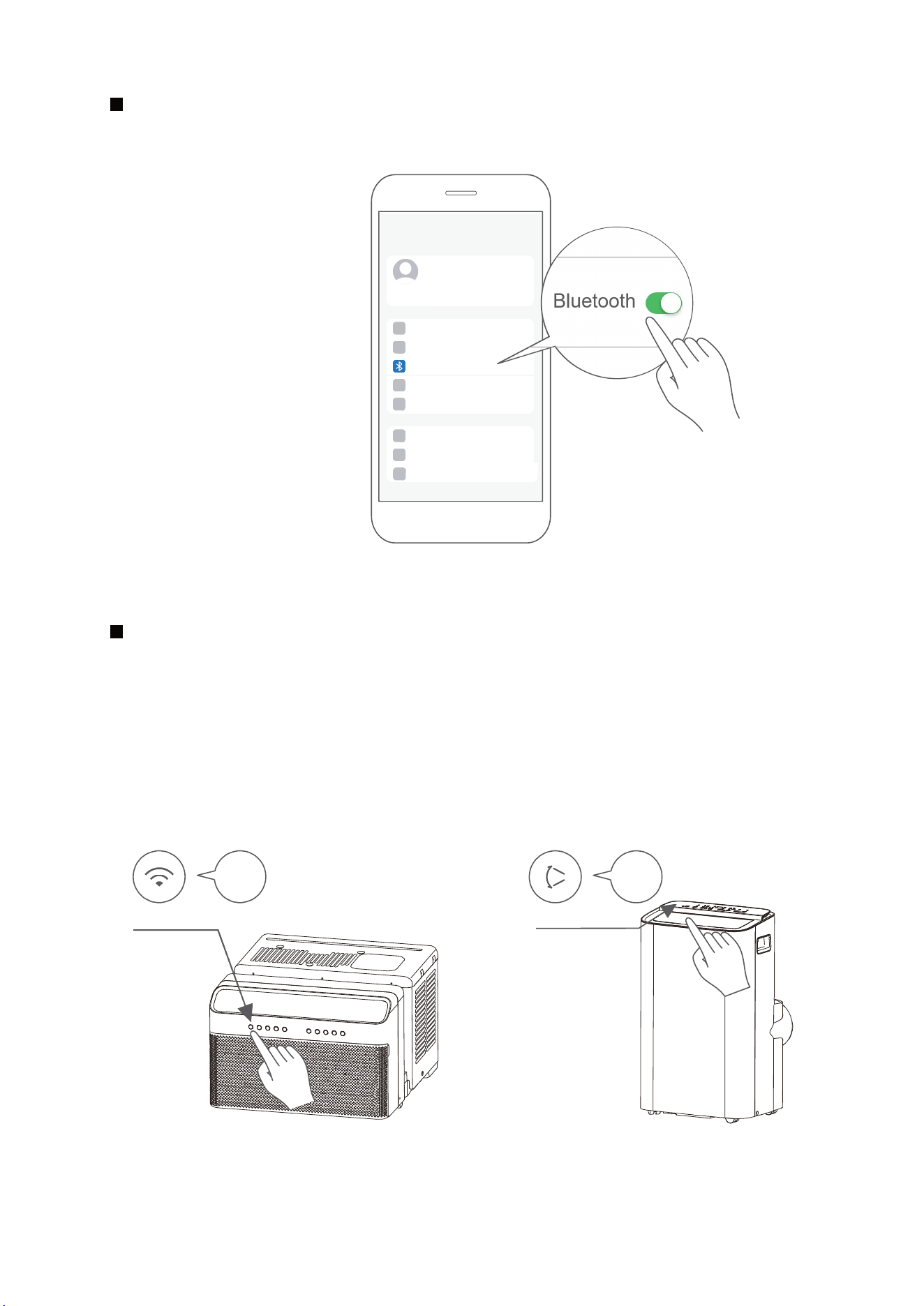
Turn on Bluetooth on your mobile device.
Step 2: Turn on Bluetooth
Settings
Bluetooth
Window AC: Hold down the CONNECT / Power button for 3 seconds to begin the pairing process
(“AP” will appear on the AC’s display).
Portable AC: Hold down the SWING / Power button for 3 seconds to begin the pairing process (“AP”
will appear on the AC’s display).
Note: Entering AP pairing mode may vary between dierent AC, please follow instruction of AC panel.
Step 3: Enter AP mode
AP
CONNECT
AP
SWING
Window AC Portable AC
31
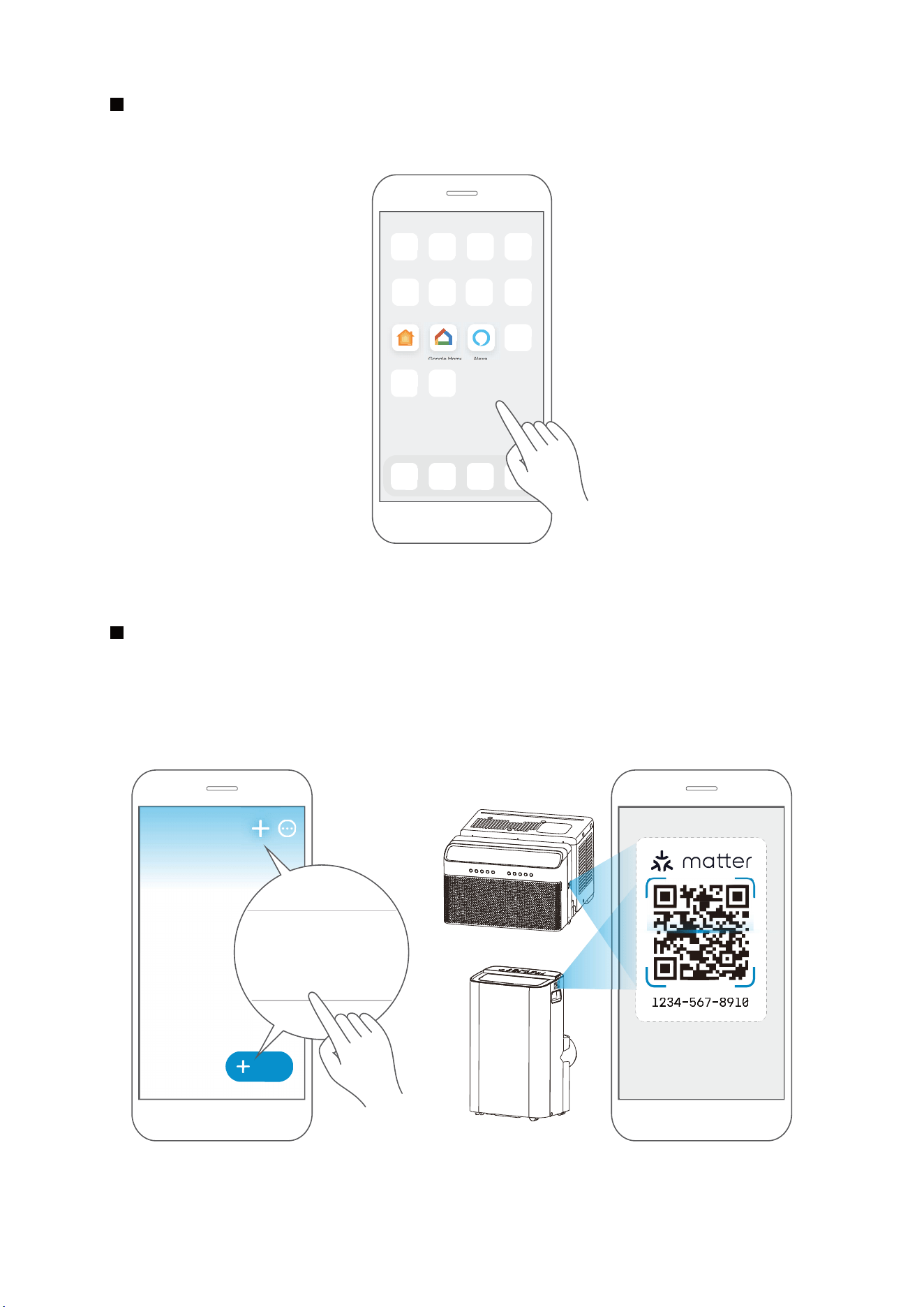
Open the Alexa, Google Home, Apple Home app on your mobile device.
Step 4: Open app
Apple Home Google Home Alexa
Tap the “+” and “Add Device/Accessory” or tap "+Add" in your app and then select Matter device and
scan the Matter QR code found on the side of the AC device. Follow the respective instructions in the
Alexa, Google Home or Apple Home app to complete the pairing process.
Step 5: Scan matter QR code
Add
Add Device/Accessory
scan
Matter QR code
32
After pairing is successful, you can control your AC’s temperature and mode settings, etc. through the
respective ecosystem app and smart speaker.
Due to a compatibility issue, the temperature value shown in the Alexa, Google Home or Apple Home
app may be 1 degree dierent from that displayed on the air conditioner. However, this will not impact
the device's ability to cool the room.
Step 6: Control device
Air conditioner
33

This device complies with Part 15 of the FCC Rules and Industry Canada’s licenceexempt RSSs.
Operation is subject to the following two conditions:
This equipment has been tested and found to comply with the limits for a Class B digital device, pursuant
to part 15 of the FCC Rules. These limits are designed to provide reasonable protection against harmful
interference in a residential installation.
This equipment generates, uses and can radiate radio frequency energy and, if not installed and used in
accordance with the instructions, may cause harmful interference to radio communications. However, there
is no guarantee that interference will not occur in a particular installation. If this equipment does cause
harmful interference to radio or television reception, which can be determined by turning the equipment
off and on, the user is encouraged to try to correct the interference by one or more of the following
measures:
--Reorient or relocate the receiving antenna.
--Increase the separation between the equipment and receiver.
--Connect the equipment into an outlet on a circuit different from that to which the receiver is connected.
--Consult the dealer or an experienced radio/TV technician for help.
We, hereby declare that this device is in compliance with the relevant provisions of RE
Directive 2014/53/EU. A copy of the full DoC is attached (Europen Union products only).
Only operate the device in accordance with the instructions supplied.
Changesormodificationstothisunitnotexpresslyapprovedbythepartyresponsibleforcompliance
could void the user's authority to operate the equipment.
This device complies with FCC radiation exposure limits set forth for an uncontrolled environment. In order
to avoid the possibility of exceeding the FCC radio frequency exposure limits, human proximity to the
antenna shall not be less than 20cm (8 inches) during normal operation.
(1) This device may not cause interference;
(2) This device must acceptany interference,including interference that may cause undesired operation
of the device.
Declaration of conformity
FCC ID: 2ADQOMDNA23
IC: 12575A-MDNA23
NOTE:
34
NOTE:
The functions shown in the Alexa, Google Home or Apple Home apps may change with updates to
their products or apps.
Setup processes and features may vary between ecosystems.
Make sure the Matter enabled app is up to date to ensure the best experience.
Periodically, we will update the device’s software to improve the experience.
Device software updates can be accomplished through the SmartHome app.
Use of the Works with Apple badge means that an accessory has been designed to work specifically
with the technology identified in the badge and has been certified by the developer to meet Apple’s
performance standards.
Apple is not responsible for the operation of this device or its compliance with safety and regulatory
standards.
is developed by the Connectivity Standards Alliance TM. This brand, related logos,
and marks are trademarks of the Alliance, all rights reserved.
App & Smart Speakers can support Matter only when using these
versions or above.
9094439556
Google Play services min version: 22.36.15
Google Home app (GHA) min version: 2.58.24.1-dogfood
Google Hub firmware min version: 1.56.324896
(appears on hub as Chromecast firmware version)
2.2.536317
16.5
Device Version
iOS 16.5iPhone
Apple Home
Pod
Alexa Echo
Device
Android
Google
Home Hub
Alexa App
35
CLEANING AND MAINTENANCE
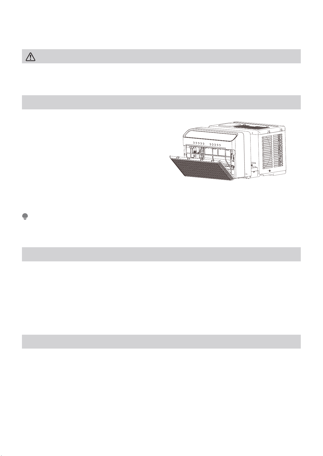
Air Filter Cleaning
Cabinet Cleaning
Winter Storage
Theairfiltershouldbecheckedatleastonceevery
two weeks to see if cleaning is necessary. Trapped
particlesinthefiltercanbuildupandreduce
performancebyrestrictingairflowthroughthecoils.
• Graspthefilterbythecenterandpullupandout.
• Washthefilterusingwarmwater.Rinsefilter
thoroughly.
• Gentlyshakeexcesswaterfromthefilter.Besure
thefilteristhoroughlydrybeforereplacing.
• Insteadofwashing,youmayalsovacuumthefilter
clean.
• Besuretounplugtheairconditionertopreventshockorfirehazard.Thecabinetandfrontmaybe
dusted with an oil-free cloth or washed with a cloth dampened in a solution of warm water and mild liquid
dishwashing detergent. Rinse thoroughly and wipe dry.
• Never use harsh cleansers, wax, or polish on the air conditioner.
• Be sure to wring excess water from the cloth before wiping around the controls. Excess water in or around
the controls will cause damage to the air conditioner.
• Plug in air conditioner.
If you plan to store the air conditioner during the winter, remove it carefully from the window according to the
installation instructions. Be careful not to spill any potentially standing water from the unit’s base pan. If water is
present, carefully drain it. Cover the unit with plastic or return it to the original carton and store in a cool dry place.
CAUTION
Clean your air conditioner occasionally to keep it looking new. Be sure to unplug the unit before cleaning to
preventshockorfirehazards.
Neverusehotwaterover104°F(40°C)tocleantheairfilter.Neverattempttooperatetheunitwithoutthe
airfilter.
NOTE
36

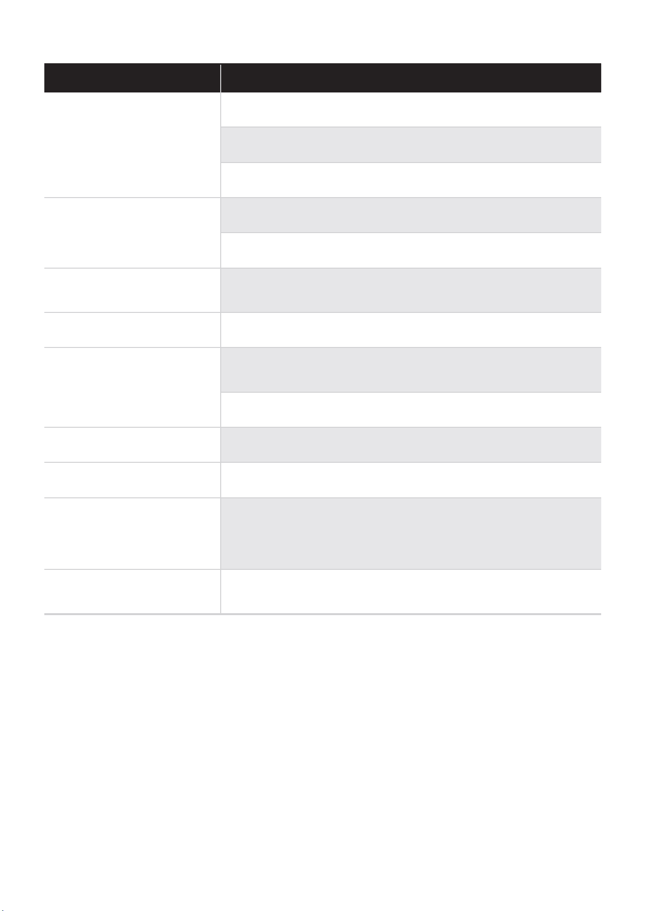
TROUBLESHOOTING TIPS
Problem Solution
Air conditioner does not start.
Wallplugdisconnected.Pushplugfirmlyintowalloutlet.
Circuit breaker tripped. Reset circuit breaker.
Check if the light on the plug is on. If it is off, press the RESET button.
Power is OFF. Turn power ON.
Unit turned off and then on quickly. Turn unit off and wait 3 minutes
before restarting.
Air from unit does not feel cold
enough.
Room temperature below 62°F (17°C). Cooling may not occur until room
temperature rises above 62°F (17°C).
Temperaturesensorbehindtheairfilteristouchingthecoldcoil.Tryto
move it so it does not contact the cold coil.
Reset to a lower temperature.
Compressor shut-off by changing modes. Wait approximately 3 minutes
and listen for compressor to restart when set in the COOL mode.
Check for potential obstructions blocking the outdoor intake/exhaust.
Clear any obstructions.
Air conditioner cooling, but room
is too warm- ice forming on
coolingcoilbehindairfilter.
Outdoor temperature below 64°F (18°C). To defrost the coil, set to FAN
ONLY mode.
Airfiltermaybedirty.Cleanfilter.RefertoCareandCleaningsection.To
defrost, set to FAN ONLY mode.
Thermostat set too cold for night-time cooling. To defrost the coil, set to
FAN ONLY mode. Then, set temperature to a higher setting.
Air conditioner cooling, but room
is too warm- NO ice forming on
cooling coil behind air filter.
Dirtyorrestrictedairfilter.Cleanfilter.RefertoCareandCleaningsection.
To defrost, set to FAN ONLY mode.
Temperature is set too high, set temperature to a lower setting.
Air directional louvers positioned improperly. Position louvers for better
air distribution.
Front of unit is blocked by drapes, blinds, furniture, etc. - restricts air
distribution. Clear obstruction in front of unit.
Any open doors, windows, or vents may allow cold air to escape. Close
any doors, windows, or vents.
The room may be too warm. Allow additional time to remove “stored
heat” from walls, ceiling, floor and furniture.
Before calling for service, review this list. It may save you time and expense. This list includes common
occurrences that are not the result of defective workmanship or materials in this appliance.
37
Problem Solution
Air conditioner turns on and off
rapidly.
Dirtyairfilter-airrestricted.Cleanairfilter.
Outside temperature extremely hot. Set FAN speed to a higher setting to
bring air past cooling coils more frequently.
Check for potential obstructions blocking the outdoor intake/exhaust.
Clear any obstructions.
Noise when unit is cooling.
Air movement sound. This is normal. If too loud, set to a slower FAN
setting.
Window vibration - poor installation. Refer to installation instructions or
check with installer.
Water dripping INSIDE when unit
is cooling.
Improper installation. Tilt air conditioner slightly to the outside to allow water
drainage.
Refer to installation instructions - check with installer.
Water dripping OUTSIDE when
unit is cooling.
Unit removing large quantity of moisture from humid room. This is normal
during excessively humid days.
Remote sensing deactivating
prematurely (some models).
Remote control not located within range. Place remote control within
26 feet & 180°, radius of the front of the unit, and pointed in the general
direction of the air conditioner unit.
Remote control signal obstructed. Remove obstruction.
.gnittes erutarepmet esaercnI .wol oot gnittes erutarepmeT.dloc oot mooR
Noise when unit starts.
A 30 second high pitched noise may occur when the unit is turned on due
to the compressor starting, This is normal.
Window does not insert into the
U-shaped slot.
Ensure that the “U-shaped” slot is in line with the window, if not, align the
slot with the window.
Ensure that the unit is not slanted too much to cause interference with
the top of the unit. Reference the installation instructions for more
information.
Unit will not connect to Wireless
or App does not work (some
models).
For additional support and troubleshooting tips, visit the “Help” tab within
the SmartHome app.
38

WARRANTY
Air Conditioner Limited Warranty
Your product is protected by this Limited Warranty:
Warranty service must be obtained from Midea Consumer Services or an authorized Midea servicer.
Warranty
• One Year Limited Warranty from original purchase date. Five Year Limited Sealed System Warranty
(includes components containing refrigerant) from original purchase date. Three Year Limited Compressor
Warranty from original purchase date.
Midea, through its authorized servicers will:
• Pay all costs for reparing or replacing parts of this appliance which prove to be defective in materials or
workmanship.
Consumer will be responsible for:
• Diagnostics, removal, transportation and reinstallation cost required because of service.
• Costs of service calls that are a result of items listed under NORMAL RESPONSABILITIES OF THE CONSUMER**
Midea replacement parts shall be used and will be warranted only for the original warranty.
NORMAL RESPONSABILITIES OF THE CONSUMER**
This warranty applies only to products in ordinary household use, and the consumer is responsible for the
items listed below:
1. Proper use of the appliance in acordance with instructions provided with the product.
2. Routine maintenance and cleaning necessary to keep the good working condition.
3. Proper installation by an authorized service professional in accordance with instructions provided with the
appliance and in accordance with all local plumbing, electrical and/or gas codes.
4. Proper connection to a grouded power supply of sufficient voltage, replacement of blown fuses, repair of loosen
connections or defects in house wiring.
5. Expenses for making the appliance accessible for servicing.
6. Damages to finish after intallation.
EXCLUSIONS
This warranty does not cover the following:
1) Failure caused by damage to the unit while in your possesion (other than damage caused by defect or
malfunction), by its improper installation, or by unreasonable use of the unit, including without limitation,
failure to provide reasonable and necessary maintenance or to follow the written installation and
Operating Instructions.
2) Damages caused by serviced performed by persons other than those authorized by Midea customer
service; or external causes such as abuse, misuse, inadequate power supply or acts of God.
3) If the unit is put to commercial, business, rental, or other use or application other than for consumer
use, we make no warranties, express or implied, including but not limited to, any implied warranty of
merchantability or fitness for use or purpose.
4) Products without original serial numbers or products that have serial numbers which have been altered or
cannot be readily determined.
NOTICE: Some states do not allow the exclusions or limitation of incidental or consequential damages.
So this limitation or exclusion may not apply to you.
IF YOU NEED SERVICE
Keep your bill of sale, delivery slip, or some other appropriate payment Record.
The date on the bill establishes the warranty period, should service be required.
If service is performed, its your best interest to obtain and keep all receipts.
This written warranty gives you specific legal rights. You may also have other rights that vary from state to state.
Service under this warranty must be obtained by following these steps, in order:
1) Contact Midea Consumer Services or an authorized Midea services at 1 866 646 4332.
2) If there is a question as to where to obtain service, contact our consumer relations Departament.
39
logo, word marks, trade name, trade dress and all versions thereof are valu-
-
marks, copyrights and other intellectual property rights, and all goodwill derived from
using any part of an Midea trademark. Use of Midea trademark for commercial purposes
without the prior written consent of Midea may constitute trademark
infringement or unfair competition in violation of relevant laws.
This manual is created by Midea and Midea reserves all copyrights thereof. No entity or
individual may use, duplicate, modify, distribute in whole or in part this manual, or
bundle or sell with other products without the prior written consent of Midea.
All the described functions and instructions were up to date at the time of printing this
manual. However, the actual product may vary due to improved functions and designs.
TRADEMARKS, COPYRIGHTS
AND LEGAL STATEMENT
40
41
DATA PROTECTION NOTICE
For the provision of the services agreed with the customer,
we agree to comply without restriction with all stipulations of applicable data
protection law, in line with agreed countries within which services to the customer
will be delivered, as well as, where applicable, the EU General Data Protection
Regulation (GDPR).
Generally, our data processing is to fulfil our obligation under contract with you and
for product safety reasons, to safeguard your rights in connection with warranty
and product registration questions. In some cases, but only if appropriate data
protection is ensured, personal data might be transferred to recipients located
outside of the European Economic Area.
Further information are provided on request. You can contact our Data Protection
[email protected]. To exercise your rights such as right to object
your personal date being processed for direct marketing purposes, please contact
us via [email protected]. To find further information, please follow the QR
Code.
The design and specifications are subject to change without prior notice for
product improvement. Consult with the sales agency or manufacturer for details.
Any updates to the manual will be uploaded to the service website, please check
for the latest version.


CW009UI-QB
16120300A31472
20230823
2023