
N
0
5805
INTEGRATED AMPLIFIER OWNER’S MANUAL
N
0
5802


1
N
0
5805 / N
0
5802 INTEGRATED AMPLIFIER / OWNER’S MANUAL
TABLE OF CONTENTS
TABLE OF CONTENTS
Overview 2
Installation 4
Unpacking, placement and ventilation 4
Power requirements, Operating states 5
Connections 6
Rear panel overviews 6
External component connections 7
Quick Listen 11
Control 11
Front-panel overview 12
Remote control overview 13
Remote control operation 14
Browser Setup Panel 15
Setup 16
Setup navigation 16
Input setup 17
Volume setup 21
Power setup 22
Display setup 22
Advanced setup 23
SSP (surround processor integration) setup 27
Troubleshooting 29
Specifications 32

2
N
0
5805 / N
0
5802 INTEGRATED AMPLIFIER / OWNER’S MANUAL
OVERVIEW
INTRODUCING THE MARK LEVINSON N
O
5805 AND N
O
5802
INTEGRATED AMPLIFIERS
Congratulations on your purchase of a Mark Levinson
®
integrated amplifier. You now possess one of the finest audio
reproduction devices in the world, a product that will provide an
exceptional music listening experience for years to come.
The N
0
5805 and N
0
5802 harness decades of superlative audio
engineering and the latest advancements to deliver unmatched
performance and value. With a bold industrial design, fully
discrete PurePath cicuitry, PrecisionLinkII DAC, MainDrive
headphone power, and potent dual monaural class AB
amplification, the N
0
5805 and N
0
5802 deliver luxurious fidelity
with premium features and flexibility. The N
0
5805 features
analog and digital inputs, while the N
0
5802 has digital inputs
only. The N
0
5805 and N
0
5802 are proudly designed, engineered,
and precision-crafted in the USA.
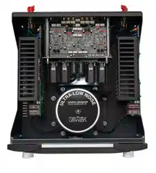
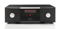
Industrial Design
Robust materials, lavish finishes and striking geometry are
hallmark attributes of Mark Levinson designs. The one-inch-
thick, bead-blasted, black-anodized, solid aluminum front
panels are machined and contoured to flow seamlessly into
the sleek glass display, which itself is recessed into a clear-
anodized aluminum bezel.
The iconic Mark Levinson hourglass knobs are redefined -
machined with a gently curved profile transitioning into a
rounded front, with feet to match. With debossed top cover vents,
screen-printed logo behind the glass panel, and aluminum
buttons, no detail has been overlooked. An elegant 5000 Series
custom aluminum IR remote control is included.
Digital Audio
The N
0
5805 and N
0
5802 offer outstanding digital audio
capability through the Mark Levinson PrecisionLink II DAC. The
latest generation ESS Sabre 32-bit D/A converter with jitter
elimination circuitry and a fully balanced, discrete current-to-
voltage converter form the heart of the digital audio processing
stage. There are seven user selectable PCM filters and 4 low-
pass filters for DSD playback.
Both models include MQA (Master Quality Authenticated)
technology, which enables playback of MQA audio files
and streams from any digital input. In addition, a Bluetooth
receiver equipped with AptX-HD for the highest quality
Bluetooth playback available.
Main drive Class A headphone power
Like the acclaimed 500 series components, The N
0
5805 and
N
0
5802 feature a MainDrive
™
headphone output which employs
a preamp output stage specifically designed with the current
and power capacity to drive headphones directly in pure class A,
without a separate headphone amp.
Amplification
The fully discrete, direct-coupled, class AB amplifier channels
get their power from an oversized (500+ VA) toroidal transformer
with individual secondary windings for the left and right
channels. The voltage gain stage employs a topology directly
descended from the acclaimed N
0
534 amplifier, which is mated
to an output stage comprising two high-speed driver transistors
operating in class A and six 260V, 15A output transistors. Four
10,000-microfarad capacitors per channel, located directly on
the output stage circuit board, easily provide enough current for
a conservative 125W/channel at 8 ohms, with significant power
increase and reliable operation into 4 and 2 ohm loads. Variable
line-level RCA outputs allow system expansion and flexibility.
Control
System integration and communication ports include Ethernet,
RS-232, IR input, and 12V trigger input and output. An internal
webpage allows setup, import and export of configurations,
and software updates using a PC and standard web browser.
In addition, drivers are available for major control systems.
OVERVIEW

3
N
0
5805 / N
0
5802 INTEGRATED AMPLIFIER / OWNER’S MANUAL
OVERVIEW
N
0
5805 Analog Input Stage
The foundation of the N
0
5805 is its proprietary PurePath
circuitry- a fully discrete, direct-coupled, dual-monaural line-
level preamp circuit, for which the Shelton design team has two
patents pending. A unique single gain stage mated to a digitally
controlled resistor network for volume adjustment maintains
maximum signal integrity and widest possible bandwidth. Each
of its three stereo line level inputs—one balanced XLR and two
single-ended, using custom Mark Levinson RCA connectors—
has its own individual high-reliability signal switching relays.
A newly designed Phono stage features a hybrid gain topology,
mating key discrete components from the acclaimed N
0
500
series Pure Phono stage with low-noise integrated circuits
for high performance and space efficiency. Also like the
N
0
500 series, a hybrid active/passive RIAA equalizer employs
precision resistors and polypropylene capacitors for exceptional
accuracy and sonic clarity. The user can select MM/MC gain
and infrasonic filter from the setup menu, while capacitive and
resistive loading settings are easily accessed from the rear
panel.
Highlights
Digital Inputs
• 1 x USB 2.0, 1 x coaxial S/PDIF,
and 2 x optical S/PDIF (№ 5805)
• 1 x USB 2.0, 2 x coaxial S/PDIF, 2 x optical S/PDIF,
and 1 x AES/EBU (№ 5802)
• 384kHz/32 bit PCM and DSD 11.2MHz capability
• Bluetooth audio input including aptX-HD support
• Full MQA decoding
Analog Inputs (№ 5805 only)
• 1 x balanced XLR stereo, 2 x RCA stereo,
1 x RCA Phono (MM/MC)
• HT processor pass-thru mode
Outputs
• Line outputs: 1 x RCA stereo (variable)
• Headphone output: 1 x 1/4-inch/6.35mm jack (front panel)
• Speaker outputs: 2 pairs high-current binding posts
Control
• Control ports: Ethernet (RJ45), RS-232 (DB9),
12V trigger input/output and IR input (3.5mm jack)
• Webpage setup, configuration import/export,
software updates
• Included handheld IR remote control
• Control modules for third-party automation
For the most up to date information please visit
www.marklevinson.com

4
N
0
5805 / N
0
5802 INTEGRATED AMPLIFIER / OWNER’S MANUAL
INSTALLATION
UNPACKING
When unpacking your N
0
5805 / N
0
5802:
• Save all packing materials in case you need to ship your
integrated amp in the future.
• Inspect your integrated amp for signs of damage during
shipment. If you discover damage, contact your authorized
Mark Levinson
®
dealer for assistance in making
appropriate claims.
• Locate and remove the accessories from the shipping carton.
Make sure that all of the items listed below are included. If
any are missing, contact your authorized Mark Levinson
dealer.
1 x IEC power cord (terminated according to the region to which
the unit is shipped)
1 x Remote control plus 2 x AAA batteries
1 x Owner’s Manual
1 x Safety information sheet
1 x hex tool for remote
Please register your N
0
5805 / N
0
5802 within 15 days of
your purchase. Register online at www.marklevinson.
com. Retain your original, dated sales receipt as proof of
warranty coverage.
PLACEMENT AND VENTILATION
• Install the integrated amplifier on a shelf with nothing above
it, such as the top shelf in an open rack, to ensure proper
ventilation. DO NOT install the integrated amplifier inside of
an enclosed cabinet or rack.
• Ensure that you install the integrated amplifier on a solid, flat
and level surface.
• Install the integrated amplifier as close as possible to
associated audio components to keep interconnecting cables
as short as possible.
• Select a dry, well-ventilated location that is out of direct
sunlight.
• DO NOT expose the N
0
5805 / N
0
5802 to high temperatures,
humidity, steam, smoke, dampness, or excessive dust.
INSTALLATION

5
N
0
5805 / N
0
5802 INTEGRATED AMPLIFIER / OWNER’S MANUAL
INSTALLATION
POWER REQUIREMENTS
The N
0
5805 is configured at the factory for 100, 115, or 230
VAC power operation at 50Hz or 60Hz. Before operating the
amplifier, ensure that the power label on the rear panel near
the AC input connector indicates the correct operating voltage.
A detachable IEC power cable intended for use in the region
where the
N
0
5805 / N
0
5802
is sold is included.
Connection to an AC voltage other than that for which the
N
0
5805 / N
0
5802 is intended can create a safety and fire hazard
and may damage the unit. If you have any questions about
the voltage requirements for your N
0
5805 / N
0
5802 or about
the line voltage in your area, contact your authorized Mark
Levinson dealer before plugging the N
0
5805 / N
0
5802 into an
AC power outlet.
WARNING! MAKE SURE all components in the audio system
are properly grounded. Do NOT defeat the safety purpose of
polarized or grounding-type plugs with “ground-lifter” or
“cheater” adapters. Doing so may cause a dangerous voltage
to build up between components, which may result in personal
injuries and/or product damage.
NOTE: The N
0
5805 / N
0
5802 is capable of delivering
remarkable sound at exceptional power levels. Depending
on your listening preferences, the demands of your
loudspeakers and the number of power amplifiers present
in your system, it is possible electrical service may become
the limiting performance factor in your system.
If this case occurs, consider installing a dedicated AC circuit
for the system. If more than one AC circuit is providing
power to your system, contact a licensed electrician to
ensure that all components are operating with the same
solid, low-impedance ground reference.
Unplug the N
0
5805 / N
0
5802 from the AC wall outlet during
lightning storms and extended periods of non-use.
CAUTION: Before moving the unit, make sure it is powered off
by removing the power cord from the AC power outlet and the
unit’s rear panel.
OPERATING STATES
The N
0
5805 / N
0
5802 has three operating states:
Off:
The AC mains power is disconnected by removing the power
cord from the rear panel.
Standby:
The
Standby
mode has three settings that can be
selected via the
Setup
menu: Green, Power Save, and Normal.
(See page 22 for more information on changing
Standby
mode
settings.)
Green:
This mode removes power from almost all of the
amplifier’s circuits, allowing the unit to be activated only via
an IR control signal, a 5V – 12V trigger or a double press
of the
Standby
button. This mode provides maximum power
conservation and is the factory-default
Standby
mode.
Power Save:
This mode removes power from the audio
circuits, but keeps the control circuitry powered and ready
to receive commands from the front panel controls, or the
remote control or the web-browser Graphical User Interface
(GUI). This mode provides moderate power conservation.
Normal:
This mode shuts off the display and mutes its
audio outputs, but keeps all of its control and audio circuits
powered. This mode provides the least amount of power
conservation but allows the N
0
5805 / N
0
5802s audio circuits
to remain warmed up to deliver optimal performance at all
times.
On:
The entire unit is powered up and all configured outputs
are active.
The N
0
5805 / N
0
5802 has an Auto Off feature that automatically
places it into the
Standby
mode after 20 minutes of no user
control input or audio signal passing through the unit. The
factory default setting for the Auto Off feature is On (engaged)
as required for certain regions. You can disable the Auto Off
feature in the
Setup
menu (see Setup on page 16).
6
N
0
5805 / N
0
5802 INTEGRATED AMPLIFIER / OWNER’S MANUAL
CONNECTIONS
CONNECTIONS
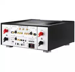
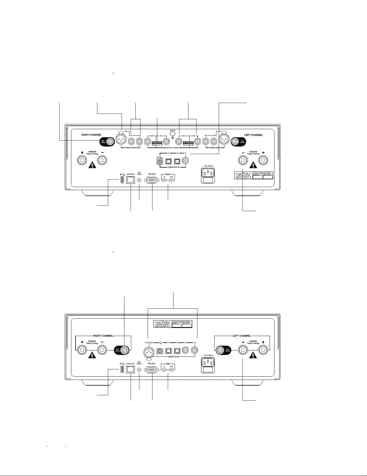
REAR-PANEL OVERVIEW N
O
5805
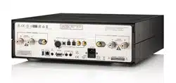
REAR-PANEL OVERVIEW N
O
5802
Line Out
(Variable)
Line Out
(Variable)
USB A for
Updates
USB A for
Updates
Ethernet
Ethernet
RS232
DB9F
RS232
DB9F
IR In
IR In
Trigger
In and Out
Trigger
In and Out
Balanced XLR
Analog In
Two Single
Ended RCA
Analog In
Moving Magnet and
Moving Coil Inputs
Digital Inputs:
• Asynchronous USB 2.0 B Audio
• 2 x Optical
• 1 Coax
Digital Inputs:
• AES XLR Input
• Asynchronous USB 2.0 B Audio
• 2 x Optical
• 2 x Coax
Speaker Terminals
Positioned for a
Variety of Connector Types
Speaker Terminals
Positioned for a
Variety of Connector Types
Capacitive and
Resistive Loading
Selection

7
N
0
5805 / N
0
5802 INTEGRATED AMPLIFIER / OWNER’S MANUAL
CONNECTIONS
EXTERNAL COMPONENT CONNECTIONS
CAUTION: Before making connections, make sure the N
0
5805
/ N
0
5802 and all associated components are powered off and
disconnected from electrical outlets.
Left and right channel loudspeaker binding posts:
The N
0
5805
/ N
0
5802 utilizes gold-plated, high-current loudspeaker binding
posts. The positive binding posts, labeled + (positive), are red;
the negative binding posts are black and are labeled – (negative).
The binding posts can accommodate speaker cables terminated
in un-tinned bare wire, spade lugs and banana plugs.
CAUTION: DO NOT OVER TIGHTEN the binding posts. DO
NOT FORCE the binding post nuts over a bent or oversized
connector. Doing so may damage the binding post.
Connect your speakers to the N
0
5805 / N
0
5802’s loudspeaker
binding posts. Use 16-gauge or larger speaker wire to ensure
the highest fidelity performance. Connect the speaker’s positive
(+) terminal to the N
0
5805’s positive (+) red binding post, and
the speaker’s negative (–) terminal to the N
0
5805’s negative (–)
black binding post. Failure to follow correct polarity (+/+, -/-)
and connecting the speakers out of phase will result in poor
bass response and vague stereo imaging.
CAUTION: Be careful not to short the positive and negative
outputs together. Do not short the positive or negative outputs
to chassis or any other safety ground.
NOTE: The audio outputs of this power amplifier are
considered Class 2 (CL2) circuits in North America. This
means the wire connected between this amplifier and
the speaker(s) shall be rated at minimum Class 2 (CL2)
and shall be installed according to the U.S. National
Electrical Code (NEC) Article 725 or Canadian Electrical
Code (CEC) Section 16.
Main Drive Headphone output (front panel):
Connect any
headphone equipped with a 1/4” TRS “Phone” plug or adaptor.
The speaker and line outputs are muted when headphones
are plugged in.
Balanced analog inputs (N
º
5805 only):
These connectors
accept left-channel and right-channel balanced input
signals from source components with balanced (male XLR)
output connectors.
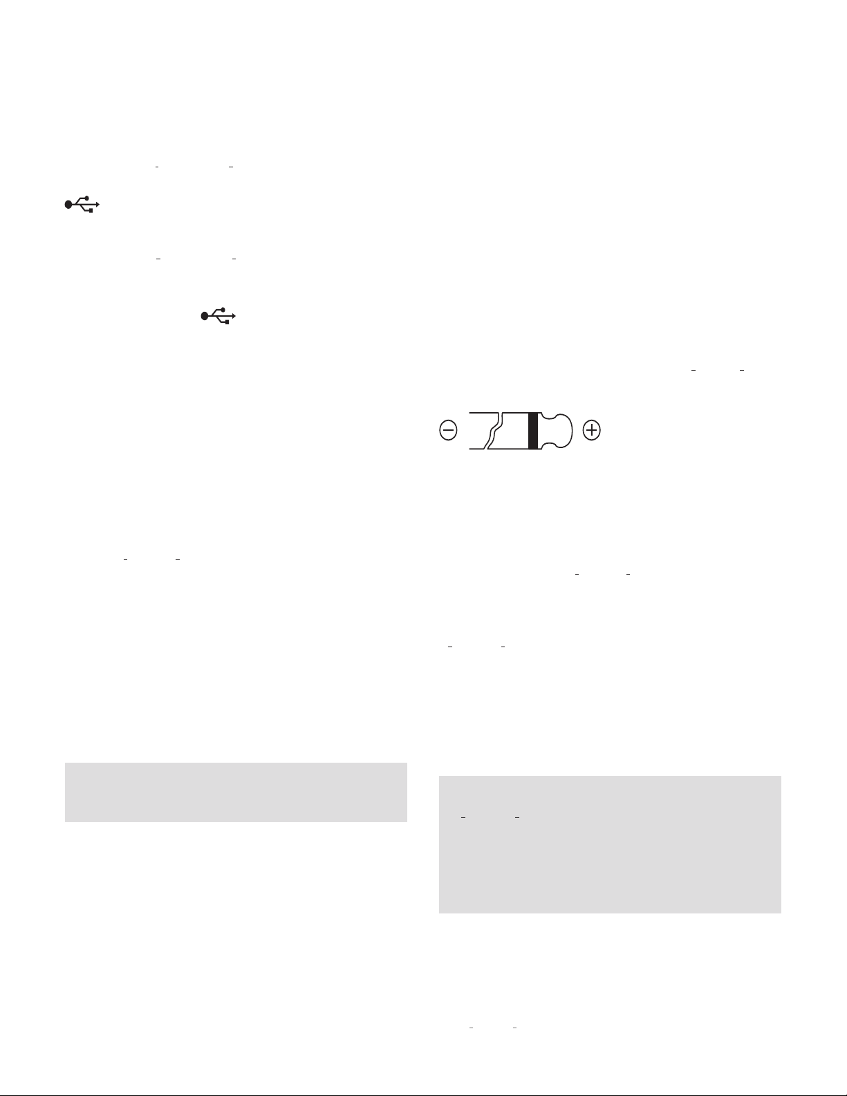
Balanced
Input Connector
(female XLR)
Pin
3
Pin
1
Pin
2
Balanced connector pin assignments:
Pin 1: Signal ground
Pin 2: Signal + (non-inverting)
Pin 3: Signal – (inverting)
Connector ground lug: Chassis ground
8
N
0
5805 / N
0
5802 INTEGRATED AMPLIFIER / OWNER’S MANUAL
Single-ended analog inputs (N
0
5805 only):
The N
0
5805 has two
analog RCA input connectors per channel (labeled S1 and S2)
that accept left-channel and right-channel single-ended input
signals from source components with unbalanced RCA type
output connectors.
Phono inputs (N
0
5805 only):
The N
0
5805 has two analog phono
preamplifier inputs per channel (labeled MM and MC) that
accept left-channel and right-channel moving magnet (MM)
and moving coil (MC) phono cartridge input signals.
Connect a turntable equipped with a moving coil cartridge to
the MM inputs. Connect a turntable equipped with a moving coil
cartridge to the MC inputs. You may connect only one turntable
to the N
0
5805. If the turntable is equipped with a ground wire,
connect it to the ground screw.
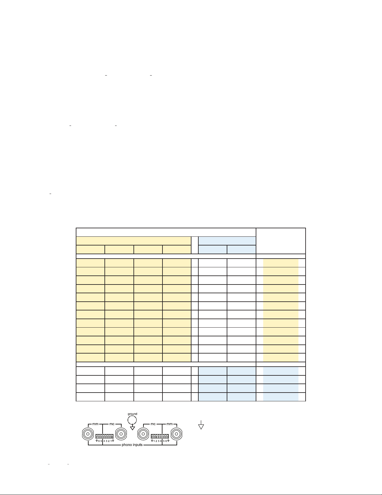
The white DIP switches adjacent to the phono inputs set the input
Resistance for moving coil cartridges and the input Capacitance
for moving magnet cartridges. Selecting the right setting is
essential for getting the best performance from your turntable.
Consult the cartridge’s owner’s manual for the recommended
load setting. Use a small tool such as a jeweler’s screwdriver
to push the switches up or down as needed. The factory default
is all switches in the down position. Follow the chart below to
make the correct settings. Choose the setting that is closest to
the specified setting. For example, if the specified MC load is
100 Ohms, use the 110 Ohm setting.
CAUTION: The volume should be set to a very low level while
re-setting the DIP switches.
CAUTION: Do not use the phono inputs for any source
component other than a turntable.
The phono inputs are balanced. Setting the ground switch
to the
up
position references the input to ground which is
sometimes useful if there is excessive noise or hum present.
1 2 3 4 5 6
x x
1000Ω
x x 500Ω
x x 250Ω
x x 200Ω
x x 125Ω
x x 110Ω
x x 90Ω
x x 82Ω
x x 62Ω
x x 52Ω
x x 43Ω
x x 37Ω
x x x x
20pF
x x x x 70pF
x x x x 120pF
x x x x 170pF
Moving Coil
Moving Magnet
Loading
Value
Loading Switches
CONNECTIONS
9
N
0
5805 / N
0
5802 INTEGRATED AMPLIFIER / OWNER’S MANUAL
Digital inputs (N
º
5805):
The N
0
5805 has four digital audio input
connectors: an asynchronous USB-B (labeled with a USB icon
), two optical (TOSLINK) S/PDIF connections (labeled T1
and T2) and one coaxial (RCA) S/PDIF connections (labeled C1).
Digital inputs (N
0
5802):
The N
0
5802 has six digital audio input
connectors: An AES/EBU-format XLR connection (labeled
AES/EBU), an asynchronous USB-B digital audio connector
(labeled with a USB icon
),
two optical (TOSLINK) S/PDIF
connectors (labeled T1 and T2), and two coaxial (RCA) S/PDIF
connectors (labeled C1 and C2).
USB port:
This USB Type-A connector allows you to perform
firmware upgrades that may be offered in the future, and to
import and export setup configurations via a standard USB drive
or memory stick (FAT32 formatted). Firmware updates may also
be accomplished via download when the unit is connected to a
local area network (LAN) via an Ethernet cable. (See page 24 for
more detailed firmware update instructions.)
Bluetooth:
Bluetooth-enabled smart devices may be paired
with the N
0
5805 / N
0
5802 to stream audio content wirelessly.
Integrated Qualcomm
®
aptX
™
-HD audio ensures your
Bluetooth
®
wireless enabled device can deliver High Definition
(HD) audio. (See Setup on page 19 for Bluetooth pairing
instructions.)
Line output connectors:
These RCA jacks provide a line-level
left-channel and right-channel signal that can be used to send
the selected input to an amplifier connected to speakers in a
second listening zone, or a recording device.
Note: The Line outputs are variable and will follow the
settings of the Volume, Balance and Mute controls.
Ethernet port:
This RJ45 jack supports connection to a home
network via Cat5e or CAT6 Ethernet cable and allows you to
access the
Setup
menu and other controls via a browser-based
setup panel.
IR input connector:
This connector accepts IR (infrared) control
signals from other equipment. See www.marklevinson.com for
IR code data.
RS-232 port:
This DB9F connector provides serial control
through a standard RS-232 protocol. See www.marklevinson.com
for RS232 code data.
Trigger output connector:
This 3.5mm tip/sleeve connector can
be used to activate other components in the audio system and
listening room, such as amplifiers, lights and window shades. A
12V 100mA DC signal is output whenever the N
0
5805 / N
0
5802 is
on. (See illustration below.)
Trigger input connector:
This 3.5mm tip/sleeve connector
can be connected to the trigger output of another system
component or control system that supplies a trigger voltage.
Whenever the units detects a voltage between 5V and 12V DC at
this connection it will turn ON. When the trigger signal at this
connection ceases the N
0
5805 / N
0
5802 will enter the
Standby
mode. (See illustration above.)
AC Mains connector:
This connector provides AC power to the
N
0
5805 / N
0
5802 when the supplied power cord is connected
from it to an AC electrical outlet. This should be the LAST
connection you make in the hookup process.
We recommend that you unplug the unit from the AC wall outlet
during lightning storms and extended periods of non-use.
NOTE: After connecting all source components to the
N
0
5805 / N
0
5802, we suggest using the
Setup
menu to
set the names of all unused inputs to “Disable.” This
will remove the unused inputs from the list of available
inputs and skip over them when scrolling through inputs.
(See Setup/Input on page 18 for more information.)
CONNECTIONS
10
N
0
5805 / N
0
5802 INTEGRATED AMPLIFIER / OWNER’S MANUAL
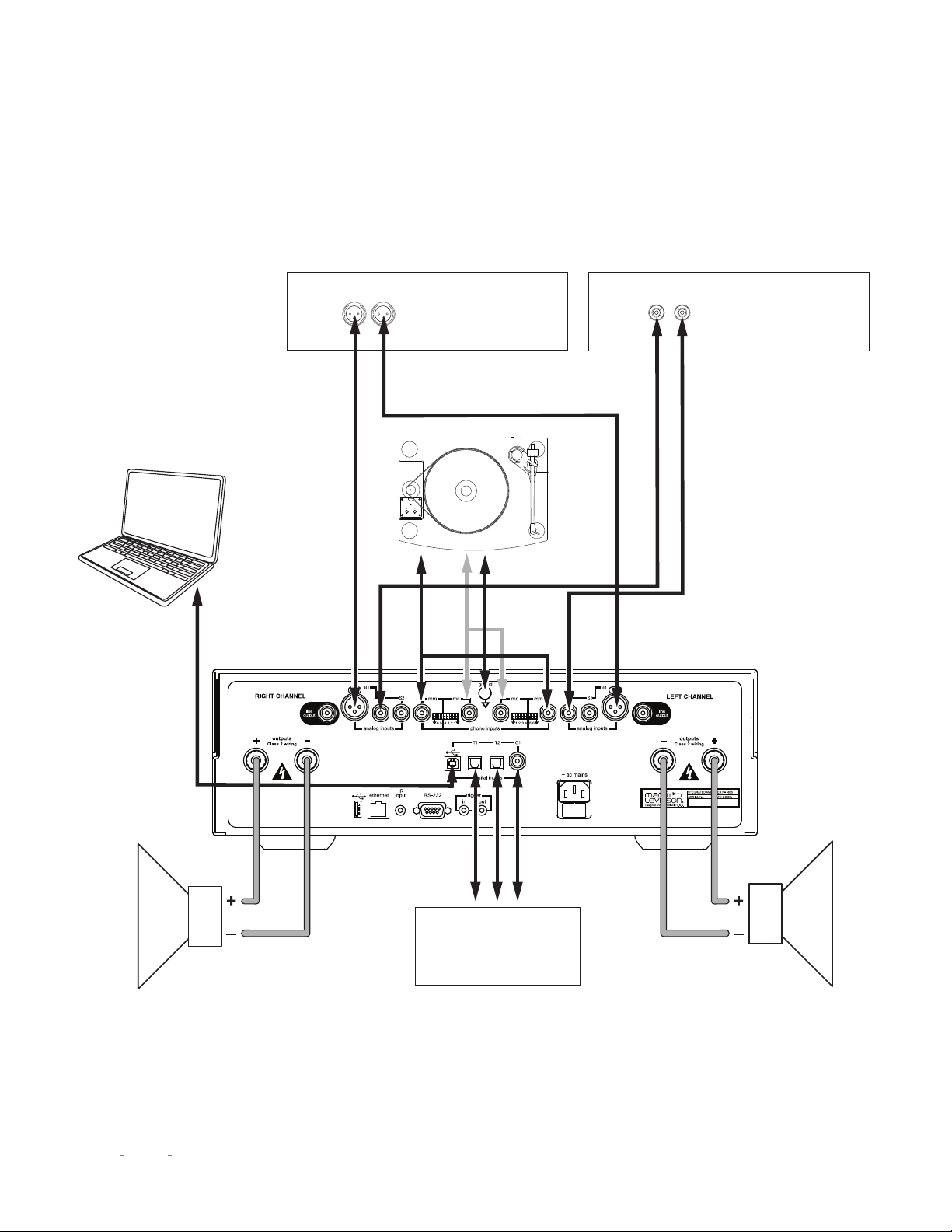
CONNECTIONS
Balanced
Analog Source
Component
Single-Ended
Analog Source
Component
Digital Source
Component
Computer
To USB
Port
Right
Speaker
Left
Speaker

11
N
0
5805 / N
0
5802 INTEGRATED AMPLIFIER / OWNER’S MANUAL
QUICK LISTEN / CONTROL
CONTROL
The N
0
5805 / N
0
5802 is highly flexible and allows a variety of
means of setup and control including front panel control knobs,
IR remote and integration with 3rd party control systems.
Additionally, an internal webpage allows setup, import and
export of configurations, and firmware updates using a PC or
tablet and a standard web browser.
1. Connect the supplied power cable to the N
0
5805 / N
0
5802’s
AC Mains connector and an electrical outlet. Power on the
N
0
5805 / N
0
5802 and all source components.
2. Press the
Standby
button on the N
0
5805 / N
0
5802’s front panel
or remote control to turn it on.
3. Rotate the N
0
5805 / N
0
5802’s input select knob or press the
Select +/– buttons on the remote to select the input for the
source component you want to hear.
4. Make sure the N
0
5805 / N
0
5802’s volume is set to a reasonable
level (30 is a good starting point).
5. Begin playing the selected source device.
6. Sit back, relax and delight in the incredible realism of your
Mark Levinson high-performance audio system.
7. For more information on how to get the best performance
and convenience from your new amplifier, read on. You will
be glad you did.
QUICK LISTEN
12
N
0
5805 / N
0
5802 INTEGRATED AMPLIFIER / OWNER’S MANUAL
CONTROL
The N
0
5805 / N
0
5802 was designed for elegant simplicity and
ergonomics. Therefore the knobs perform a variety of functions
depending on the operating mode. There are two modes of
operation, Listening mode and Setup mode, and three modes of
standby, Green, Power-save, and Normal.
Please read this section carefully and take the time to learn
the operating modes. We strongly recommended you turn
your volume very low or all the way down before entering the
setup mode.
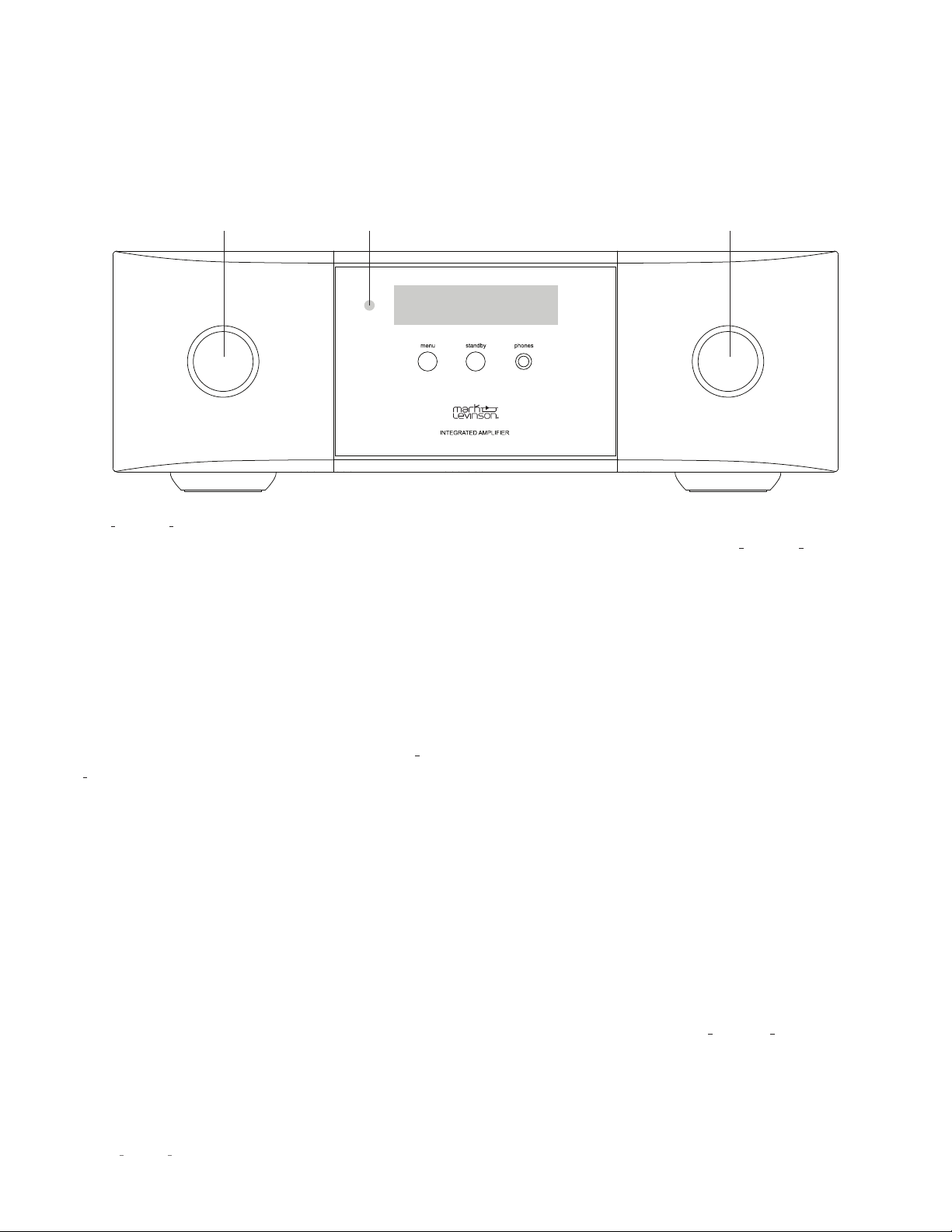
Standby button and LED:
Press this button to put the N
0
5805 /
N
0
5802 into and out of the
Standby
mode. The LED illuminates
steady RED when the unit is On. When the unit is in the standby
state, the LED flashes slowly.
Input/Select knob:
When in listening mode rotate this knob
to select the desired source signal to send to all outputs. The
front panel display indicates the name and volume level of the
selected input. (Note: The Select knob will bypass any input
for which the Input Name parameter is set to “Disabled” in the
setup mode.) When in setup mode, turning this knob will scroll
through menu choices.
IR receiver:
The IR receiver receives commands from the
included remote control when the rear-panel IR Input is not
being used.
Menu button:
Press this button to display the
Setup
menu,
which you can use to customize the N
0
5805 / N
0
5802 to suit
your other system components and individual preferences. This
button performs a "Back" function when more than two levels
deep into menu parameters.
Headphone output:
Connect any headphone equipped with a
1/4" tip/ring/sleeve “Phone” plug or adaptor. When headphones
are plugged in the speaker and line outputs are muted.
Volume/Scroll/Enter:
This knob is a rotary encoder and switch.
When in listening mode, this knob acts as a volume control.
Turn this knob to adjust the volume level. When the setup mode
is activated by pressing the
Menu
button, this knob/button
scrolls through the setting options and acts to select or deselect
the displayed choice when pushed inward. The Enter button
displays the sampling rate for digital inputs when in listening
mode. If "MQA" or "MQA." is displayed along with the sampling
rate, it indicates that the product is decoding and playing an
MQA stream or file. "MQA." indicates it is playing an MQA Studio
file, which has either been approved in the studio by the artist/
producer or has been verified by the copyright owner.
Front Panel Display:
This 32-character alphanumeric display
provides information about the N
0
5805 / N
0
5802’s operating
status. During normal operation, it indicates the name and
volume level of the selected input.
FRONT-PANEL OVERVIEW
Input/ Select Knob IR Receiver Volume/Scroll/Enter

13
N
0
5805 / N
0
5802 INTEGRATED AMPLIFIER / OWNER’S MANUAL
CONTROL
REMOTE CONTROL
REMOTE CONTROL OVERVIEW
Standby:
Press this button to put the N
0
5805/ N
0
5802 into and
out of the
Standby
mode. Press this button twice to wake up unit
from green
Standby
mode.
Input +/-:
Press these buttons to select the desired input. Allow
a moment for the relays to switch. The name and volume level
of the navigate to input is indicated on the front-panel display.
These buttons are also used to select functions in the Setup
mode (see page 16).
Volume +/– buttons:
Press these to adjust the volume level of
the speaker, line, and headphone outputs. The minimum volume
level is 0; the default maximum volume level is 80, but you can
change that value in the
Setup: Volume
menu (see page 21).
Menu:
Press this button to display the
Setup
menu, which you
can use to customize the
N
0
5805 / N
0
5802
to suit your system
and preferences. The word “Setup” appears on the front
panel display when the
Setup
menu is active. This button
performs a "Back" function when more than two levels deep
into menu parameters.
Mute:
Press this button to mute and unmute the speaker, line
and headphone outputs by the amount determined in the
Setup
menu (the default value is -40dB). The word “Mute“ appears on
the front panel display when the mute function is engaged.
Enter:
Press this button to select or deselect a menu item when
in the Setup mode.
Balance:
Press this button to set the left-to-right channel
balance. The symbols < - - L/R - - > appear in the front panel
display. To change balance use the Volume + button to shift
channel balance to the right in 1 dB steps. Use the Volume –
button to shift channel balance to the left. Maximum shift is
-20dB, followed by the reverse channel turning off.
While in Balance mode other controls will not operate. To exit
the Balance mode, push the Balance button a second time.
Bluetooth Transport control:
When using a Bluetooth source
these buttons control navigation of the program material when
used with compatible Apps.
standby
input
volume
enter menu
balance mute

14
N
0
5805 / N
0
5802 INTEGRATED AMPLIFIER / OWNER’S MANUAL
REMOTE CONTROL OPERATION
Battery Installation
Your N
0
5805 / N
0
5802 remote control comes with two AAA
alkaline batteries. To install the batteries, use the included
hex tool to remove the battery cover, insert the batteries and
replace the battery cover and hex screw. Be sure to observe
proper battery polarity.
standby
input
volume
enter menu
balance mute
Using the Remote Control
When using the remote control, aim it toward the unit’s front
panel IR receiver. Make sure that no objects, such as furniture,
block the remote’s view of the receiver. Bright lights, fluorescent
lights, and plasma video displays may interfere with the function
of the remote.
• The remote has a range of about 17 feet (5m), depending on
the lighting conditions.
• You can use the remote at an angle of up to 45° on either side
of the unit.
• Placing the amplifier behind tinted glass will reduce the
remote control’s effective range.
If the remote control operates intermittently, replace both
batteries with new ones.
CONTROL
15
N
0
5805 / N
0
5802 INTEGRATED AMPLIFIER / OWNER’S MANUAL
BROWSER SETUP PAGE (BSP)
The BSP is a highly conveient means of keeping the firmware of
your amplifier up to date, for performing setup functions, and
monitoring operational faults and temperature. It is accessed
via a major web browser on a PC or tablet. In order to access the
BSP, you must first connect the unit to your Local Area Network
(LAN). If there is no easy access to a LAN there are other means
of setup and control, discussed elsewhere in this manual.
• Connect the Ethernet port on the rear panel of the N
0
5805 /
N
0
5802 to an ethernet port on your home network’s router,
switch or hub with a Category 5e or Category 6 Ethernet cable.
• Find the IP address of your unit by navigating through the
Setup menu to Advanced/Network/IP.
• Open a browser in a PC or tablet that is connected to your
home LAN.
• Enter the IP address of your unit in the address line.
• The amplifier’s Browser Setup Panel Home page will appear
on the screen.
• The BSP controls are intuitive and behave much like the front
panel and remote controls.
NOTE: We do not recommend using the BSP as a
substitute for the front panel or remote controls for real-
time volume, input selection or any other listening mode
functions due to network latencies.
NOTE: The front panel display is replicated on the top of
Home
and
Advanced
Update pages
CONTROL

16
N
0
5805 / N
0
5802 INTEGRATED AMPLIFIER / OWNER’S MANUAL
SETUP
SETUP MENU NAVIGATION
The
Setup
menus on your Mark Levinson integrated amplifier
allow you to customize and configure the unit for higher
performance, power economy, and convenience.
There are two means for accessing and navigating the
Setup
menu: via the front panel display using the front panel or
remote control, or via the Browser Setup Page on a networked
browser-enabled device. Regardless of the method you choose,
the procedures are similar.
Remote and Front Panel Operation
Press the
Menu
button to display the
Setup
menu on the
integrated amplifier’s front-panel display. When the
Setup
menu is active, use the Select knob to scroll through options,
the
Select
Knob on the front panel or Enter button on the
remote to select and deselect options, and the
Volume
knob to
adjust parameters. To move back a level in the menu structure
(or exit the
Setup
menu), press the
Menu
button repeatedly until
the desired menu appears in the display.
Browser Setup Page (BSP) Operation
Connect your Mark Levinson integrated amplifier to a PC or
tablet via your home network and open a browser. Simply type
in your units IP address into a major browser connected to the
same network as the
N
0
5805 / N
0
5802
, and the BSP will appear
in a few moments. Network speed and quality of the connection
will affect the response time of the BSP (see page 15 for
instructions on finding the IP address on your
N
0
5805 / N
0
5802
).
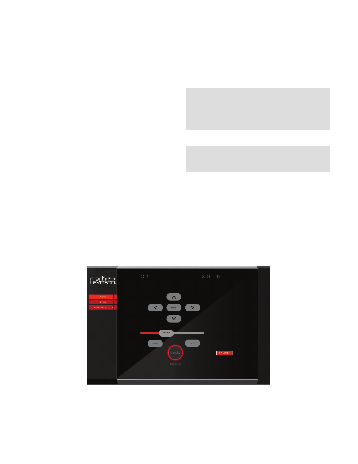
The
Home
screen displays the current active input name near
the top of the screen, the current volume level in the slider and
navigation controls. In addition there is a SW update button
which provides a one touch update from our FTP site. CAUTION:
If you choose to update the SW, DO NOT interrupt the process.
Click the
Menu
icon to activate the setup mode. When the
Setup
menu is active, use the Left < and Right > arrows to scroll
through options, use the Enter icon to select and deselect
options, and the up
�
and down
ˇ
arrows to adjust parameters.
To move back a level in the menu structure (or exit the
Setup
menu), click the
Menu
button repeatedly until the desired menu
appears in the display.
SETUP
17
N
0
5805 / N
0
5802 INTEGRATED AMPLIFIER / OWNER’S MANUAL
SETUP
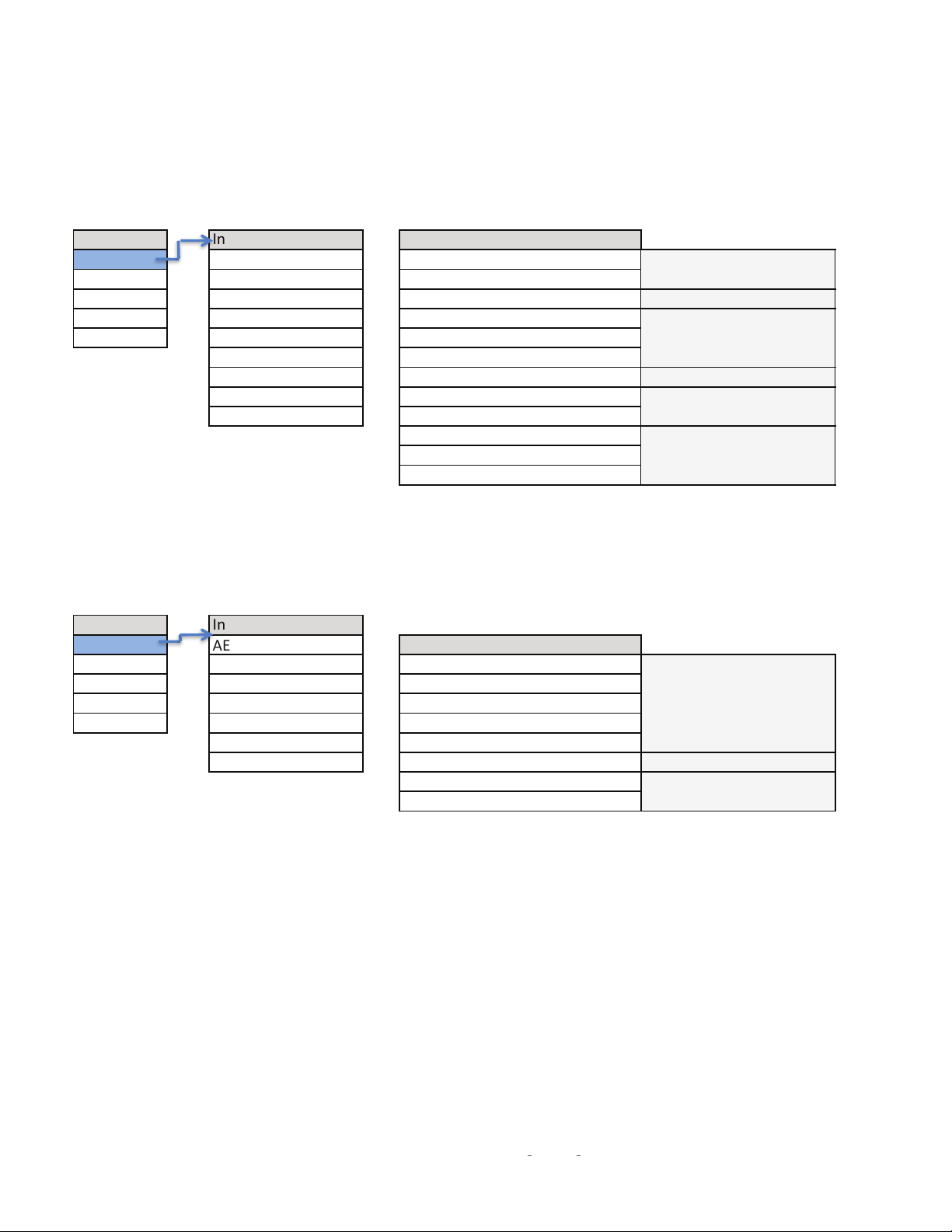
INPUT SETUP (5805)
INPUT SETUP (5802)
Setup Menu Input Setup Set Input X
Input
B1 [analog XLR] Name=XXX
Volume
S1 (analog RCA) Offset=XXX
Power
S2 (analog RCA) SSP=On/Off
Display
Phono (analog) PCM Filter=XXX
Advanced
C1 (digital coaxial) PLL Lock= Normal/Wide
T1 (digital optical) Upsample=On/Off
T2 (digital optical) DSD Filter= XXX
USB BT Name
BT (Bluetooth) BT Pairing= Enable/Forget
Ph Balance= +/- 3dB
Infra Filt = On/Off
Phono Type= MM/MC
Available for analog inputs
Available for USB input
Available for all inputs
Available for digital and
Bluetooth inputs only
Available for Bluetooth
input only
Available for phono input
only
Setup Menu Input Setup
Input
AES [Digital XLR]
Set Input X
Volume
C1 (digital coaxial) Name=XXX
Power
C2 (digital coaxial) Offset=XXX
Display
T2 (digital optical) PCM Filter=XXX
Advanced
T2 (digital optical)
PLL Lock= Normal/Wide
USB Upsample=On/Off
BT (Bluetooth) DSD Filter= XXX
BT Name
BT Pairing= Enable/Forget
Available for USB input
Available for Bluetooth
input only
Available for all inputs
18
N
0
5805 / N
0
5802 INTEGRATED AMPLIFIER / OWNER’S MANUAL
The following settings are available for all inputs:
Name:
This option offers a choice of preset names for the
selected input (CD, SACD
™
, DVD, Blu-ray
™
, DAC, EQ, etc.).
Additionally, the following names are available for each input:
Disabled:
This option removes the selected Input from
the list of available inputs. The Input will be skipped when
scrolling through the inputs.
Custom:
This option allows you to enter a custom name
for the selected input. Use the Select knob to select the
character you want to change, use the Volume control to
choose from the list of available characters and press the
Enter button to confirm each character. After the ninth
character is entered, the new name will be saved.
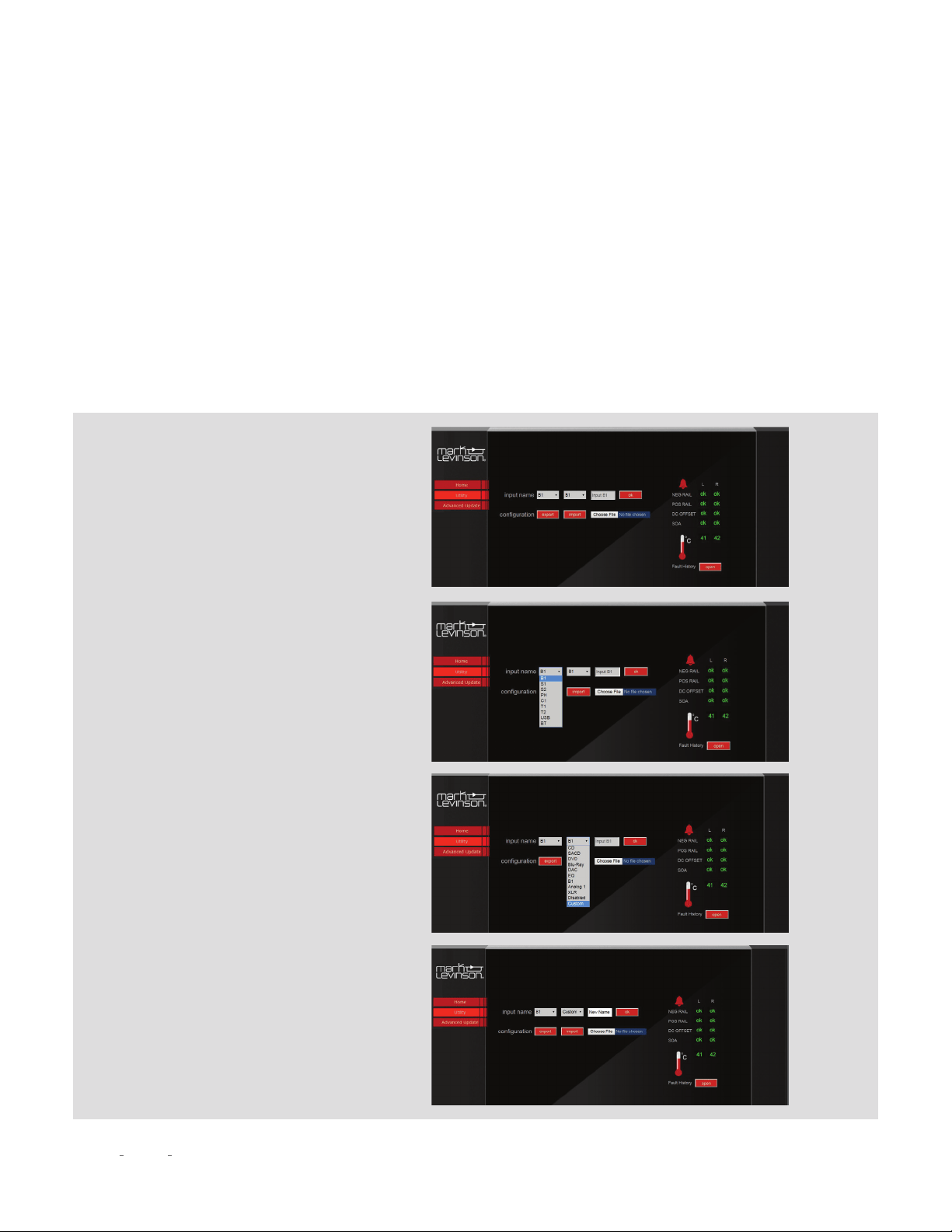
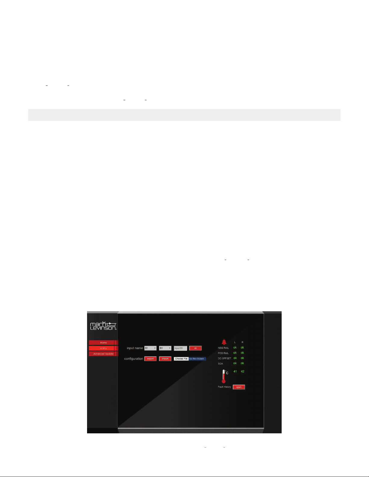
Browser Setup Page method:
The easiest way to change input name is
to select the
Utility
tab on the BSP.
Select an alternate name (or
Disable
, or
Custom
) from the next drop down menu
and push OK to save.
If you selected
Custom
, you can type the
custom name in the text box and press OK
to save.
Select the input you want to rename
from the first drop-down menu. These
correspond with the labeled inputs on the
rear panel.
SETUP

19
N
0
5805 / N
0
5802 INTEGRATED AMPLIFIER / OWNER’S MANUAL
Offset:
The output level of audio devices can vary from brand-
to-brand and model-to-model, making some devices play
louder or quieter than others. The Offset adjustment allows you
precisely compensate for source volume differences so that all
connected devices play at a similar volume level. The setting
offers a range of –12.0dB to +12.0dB, in 0.5 dB steps.
The following settings are available only for digital and
Bluetooth inputs:
PCM Filter:
This setting lets you set the filter characteristic for
PCM digital content such as the digital output from a CD player.
We recommend trying several of these filters with the types
of music you typically listen to and choose the one you prefer
There are no right or wrong choices.
The available filters are:
• Apodiz Fast
• Hybrid fast
• Brickwall
• Fast linear
• Slow linear
• Slow minimum
• Fast minimum
“Fast” filters provide steeper roll-off at high frequencies
and therefore do a better job of attenuating unwanted high
frequency “aliased” signals. However, they exhibit more ringing
on signal transients.
“Slow” filters exhibit less ringing on transients, but they do a
poorer job of attenuating unwanted high frequency signals.
“Linear Phase” filters exhibit symmetric pre- and post-ringing,
i.e., they ring before and after the transient signal.
“Minimum Phase” filters exhibit only post-ringing, which some
listeners feel sounds more natural, but they typically ring for
longer than linear phase filters.
The “Hybrid” filter blends some linear phase and some
minimum phase characteristics to achieve good high frequency
attenuation with reduced pre-ringing.
The “Apodizing” filter blends linear phase characteristics with
techniques to reduce pre and post-ringing.
The “Brick Wall” filter is optimized purely for attenuating
unwanted high frequency aliased signals.
The following setting is available only for analog inputs B1, S1,
S2 (N
O
5805 only):
SSP:
This setting configures the selected analog input for
integration with a multichannel surround sound processor.
The Default setting is "Off". Selecting "On" will pass the signal
though the outputs at unity gain and disable volume control.
(See SSP Setup on page 28 for more information.)
PLL Lock:
Normal –
This is the default setting and is appropriate for
almost all sources.
Wide –
Choose this setting if you experience noise or signal
dropouts (most likely from high jitter sources such as cable
TV set-top boxes).
Upsample On/OFF:
“Up-sampling” is the process of increasing the effective
sampling rate of a digital audio signal. When the user selects
this option in the N
0
5805/ N
0
5802, signals at 44.1, 88.2, or
176.4kHz are up-sampled to 352.8kHz, and signals at 48,
96, and 192kHz are up-sampled to 384kHz. Because these
lower resolution signals inherently have fewer samples per
second, it is in theory not possible to perfectly re-create the
additional samples that would have been present in a higher
resolution signal. However, the advanced up-sampling
algorithm in the
N
0
5805 / N
0
5802
is able to approximate these
additional data points very well, and with most program
material it offers a noticeable subjective improvement. Just
like the user’s choice of digital filter, it is neither “right” nor
“wrong” to enable or disable up-sampling; it is entirely a
matter of preference.
Selecting "Off" will maintain the original sample rate.
BT Pairing:
Set to Enable and press
Enter
to start pairing. Start pairing
procedure on your Bluetooth device. The name ML580X
followed by a 4 digit identifier unique to each unit should
appear on your device. Select this to complete pairing.
Set to
Forget
to unpair and forget your device.
SETUP

20
N
0
5805 / N
0
5802 INTEGRATED AMPLIFIER / OWNER’S MANUAL
BT Name:
This displays the Bluetooth Name that will appear on your
Bluetooth player device when scanning to pair. This name
cannot be changed.
The following setting is available only for the asynchronous
USB input:
DSD Filter:
This setting lets you set the low-pass filter
characteristic for DSD high-resolution digital content. You can
select from roll-offs that begin at 47kHz, 50kHz, 60kHz or 70kHz.
The audible effects of the different roll-off characteristics are
subtle and will vary depending on the type of musical content
and the high-frequency bandwidth of your speakers and
headphones. Feel free to experiment to find the DSD filter
setting that sounds best to you.
The following settings are available only for the Phono input
of the N
O
5805:
Cartridge Type:
Select either moving magnet (MM) or moving
coil (MC) cartridge.
Infrasonic Filter:
This option sets the infrasonic “rumble” filter
on or off.
Balance:
This option applies balance adjustment to the Phono
input from -3dB to +3dB in 0.5 dB steps.
NOTE: After connecting all source components to the
N
0
5805 / N
0
5802, we suggest using the
Setup
menu to
set the names of all inputs that are not being used to
“Disabled.” This action will remove the unused inputs
from the list of available inputs, thereby making source
selection faster and more convenient.
SETUP
21
N
0
5805 / N
0
5802 INTEGRATED AMPLIFIER / OWNER’S MANUAL
VOLUME
Setup Menu Volume
Input
Max-XXX
Volume
Mute=XXX
Power
Turn On=XXX
Display
Taper=XXX
Advanced
The Volume settings let you customize the action of the
N
0
5805
/ N
0
5802
Volume and Mute functions.
Max Vol:
This setting determines the maximum volume level
setting in 0.5dB increments between 40.0dB and 80.0dB. The
factory default maximum volume is 80.0dB. Set this value to
the volume slightly below where your speakers start to distort
audibly.
Mute:
This setting lets you set the amount of Speaker output
and Line output level attenuation that occurs when the Mute
button is engaged, in 0.5dB increments between –10dB and
–80.0dB. The factory default mute attenuation is –40dB.
Turn On:
This control lets you set the initial volume upon turn-
on. Choose a turn-on volume level in 0.5dB increments between
10.0dB and 60.0dB. The factory default setting is 40.0dB.
Last:
When selected, sets the turn-on volume level to the last
used volume setting.
CAUTION: Setting the Turn On parameter to “Last” can result
in louder-than-expected power-up volume if the N
O
5805
/ N
0
5802 was set to a high volume level setting when last
powered down.
Taper:
This setting lets you choose the desired taper for the
volume control from the following options:
Mode 1:
The faster you rotate the volume knob, the more
quickly the volume will change. Slowly turning the knob
slows the rate the volume changes, allowing you to make
precise adjustments in the listening level.
Mode 2:
Similar to Mode 1, with a “faster” response curve,
with more gain change for a similar range of knob travel.
Mode 3:
When increasing the volume the volume changes
quickly through the low volume range, and then decelerate
in the higher range, for precision adjustments. When
decreasing the volume the control works oppositely,
changing quickly through the high volume range and
decelerating in the lower range.
SETUP
22
N
0
5805 / N
0
5802 INTEGRATED AMPLIFIER / OWNER’S MANUAL
POWER
Setup Menu Power
Input
Standby = XXX
Volume
Auto Off= On/Off
Power
Display
Advanced
The Power parameters let you customize power-related
functions.
Standby:
This setting lets you set the
Standby
mode to one of
the following options:
Green:
This mode removes power from almost all of the
N
0
5805 / N
0
5802’s circuits, allowing the unit to be activated
only via an IR control signal, a 5V – 12V trigger voltage or a
press of the
Standby
button. This mode provides maximum
power conservation and is the factory-default
Standby
mode.
Power Save:
This mode removes power from the N
0
5805
/ N
0
5802’s audio circuits but keeps the control circuitry
powered and ready to receive commands from any of
the control inputs. This mode provides moderate power
conservation.
Normal:
This mode shuts off the unit’s display and mutes its
audio outputs, but keeps all of its control and audio circuits
powered. This mode provides the least amount of power
conservation but allows the audio circuits to remain warmed
up to deliver optimal performance at all times.
Auto Off:
This setting lets you engage or disengage the Auto
Off function, which puts your N
0
5805 / N
0
5802 into the
Standby
mode after 20 minutes of inactivity (no audio signal, and no
user- control input).
DISPLAY
Setup Menu Display
Input
Auto Off = On/Off
Volume
Timer = 10s/3s
Power
Display
Advanced
The Display function allows you to choose whether the front
panel display stays on all the time), or turns off after a selectable
amount of time.
Auto Off:
When set to Off, the display remains lit as long as the
unit is in listening mode. When set to On, the display will turn off
after 3, 5 or 10 seconds.
Timer:
The timer determines when the display turns off, after
3, 5, or 10 seconds.
SETUP
23
N
0
5805 / N
0
5802 INTEGRATED AMPLIFIER / OWNER’S MANUAL
ADVANCED
Setup Menu Advanced
Input
Firmware
Volume
Config
Power
Network
Display
Trigger
Advanced
Front IR
The Advanced section of the
Setup
menu gives you access
to a range of configuration and administrative settings
and functions.
Firmware:
This menu gives you access to the following
firmware-related functions:
Version:
Push
Enter
to display the version number of the
currently loaded firmware. Pushing
Enter
a second time will
show the date of the version, and then automatically scroll
and display the versions of the individual componants of the
update package. (This setting is informational only, and does
not provide any user adjustments.)
To check if your unit’s Firmware is up to date, go to the N
0
5805
/ N
0
5802 product page on www.MarkLevinson.com, select the
Downloads tab and look for the latest Firmware update file.
If there is a later version, you may use either of the options
described below to update your unit. If your unit’s Firmware
version is the same as the one displayed on the website, no
further action is required.
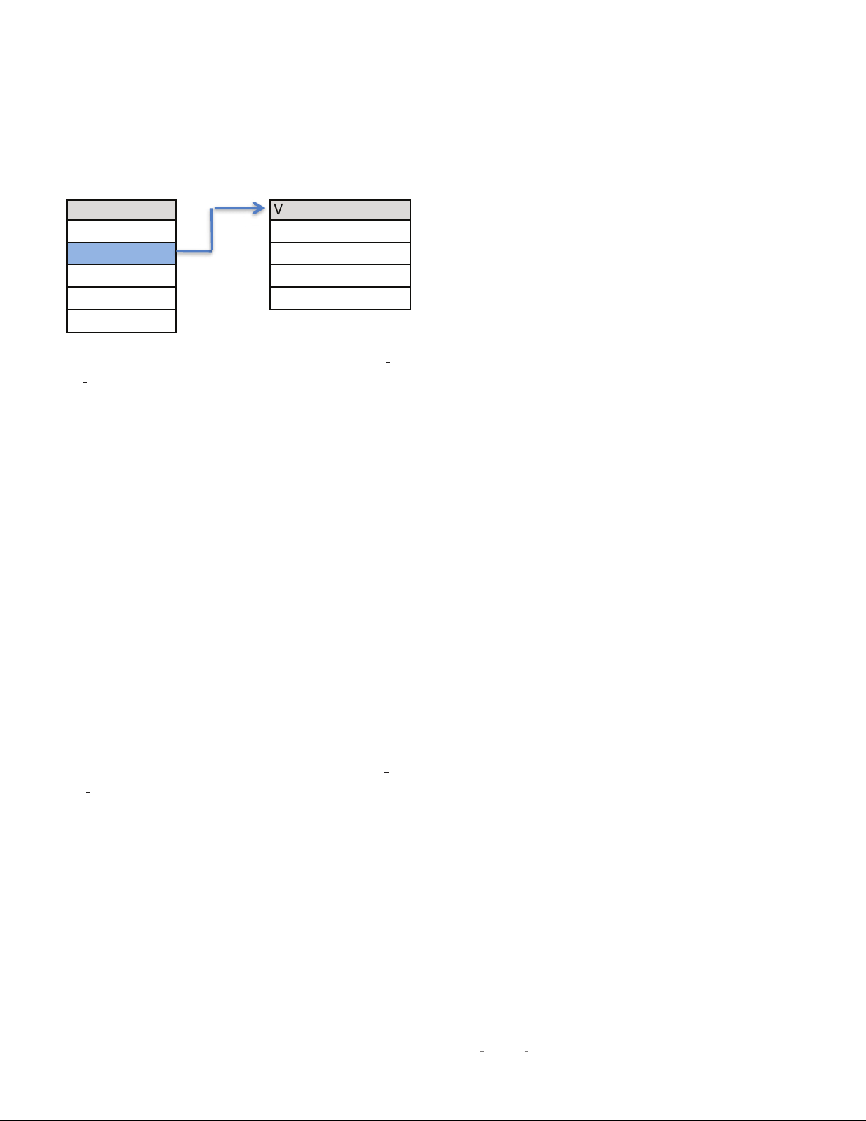
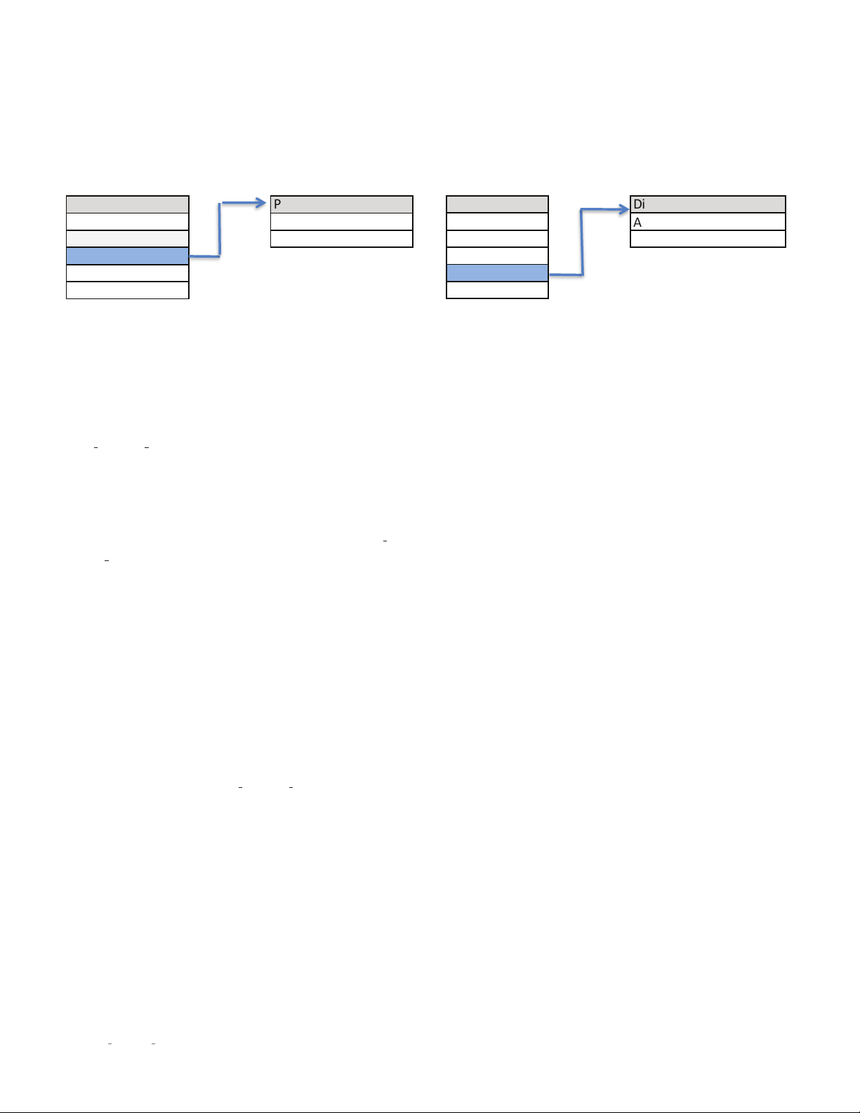
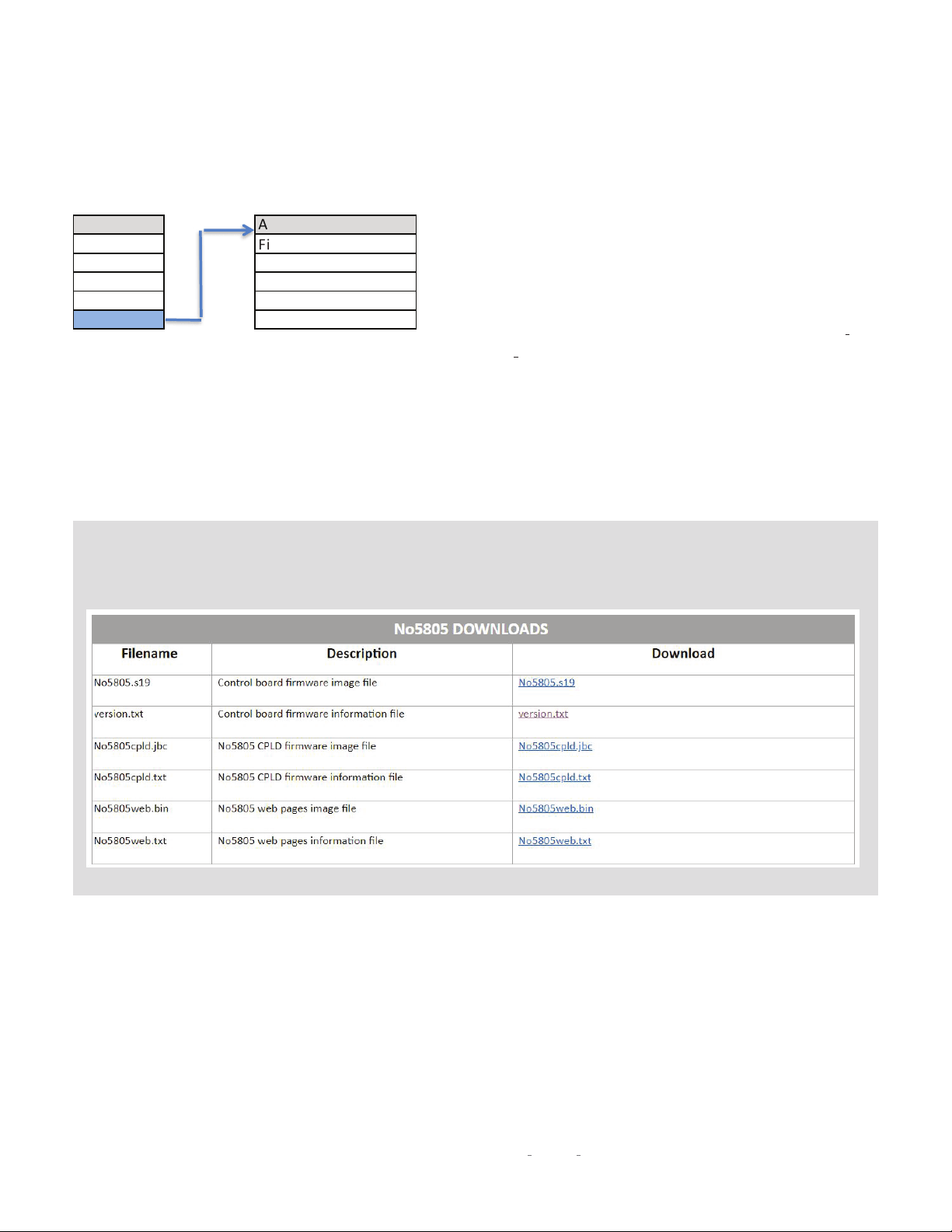
Browser Set Up Page method:
Select the
Advanced Update
tab on the Browser Setup Page, and push the
Go FTP Site
button near the bottom of the page to view
a list of available downloads. Click each of the txt files to see the version number of each type of software.
SETUP

24
N
0
5805 / N
0
5802 INTEGRATED AMPLIFIER / OWNER’S MANUAL
Update:
Lets you update your N
0
5805 / N
0
5802’s firmware,
either from a drive inserted in the rear-panel USB port or via
a web browser. (For browser connection guidance see Browser
Setup Page (BSP) on page 25.)
ENET:
Select this if your N
0
5805 / N
0
5802 is connected to
a home network. The unit will access the Mark Levinson
server and download the latest firmware. The download and
installation process takes at least 15 minutes and should not
be interrupted. The unit will cycle through several stages of
downloading and installing new operating files and go in and
out of
Standby
mode. BE PATIENT. You will know when the
process is almost over when you see “Booting…” followed by
“Starting N
0
5805…” followed by “Firmware Version [number]…”
followed by “Starting..” The unit will then enter
Standby
mode.
Wait for the
Standby
LED to start blinking before attempting to
turn on the unit. BE PATIENT.
(If you select ENET when the unit is not connected to a network
the unit‘s display shows “Failed” to remind you to connect to a
network and begin downloading the firmware.)
To update via a flash drive:
1. Download the firmware file from the product page at
MarkLevinson.com and save it to a USB drive
2. Select USB and press Enter
3. The N
0
5805 / N
0
5802 will read the USB drive. (The display
will show “Check Update” while the drive is being read.)
4. When the N
0
5805 / N
0
5802 finds a valid firmware file on
the drive, the display will show “Downloading.”
• If the N
0
5805 / N
0
5802 does not find a valid firmware
file on the drive, the display will show “Not Available.”
The installation process takes at least 15 minutes and should
not be interrupted. The unit will cycle through several stages
of downloading and installing new operating files and go in
and out of
Standby
mode. BE PATIENT. You will know when the
process is almost over when you see “Booting…” followed by
“Starting N
0
5805 (or N
0
5802)…” followed by “Firmware Version
[number]…” followed by “Starting..” The unit will then enter
Standby
mode. Wait for the
Standby
LED to start blinking before
attempting to turn on the unit. BE PATIENT.
SETUP
25
N
0
5805 / N
0
5802 INTEGRATED AMPLIFIER / OWNER’S MANUAL
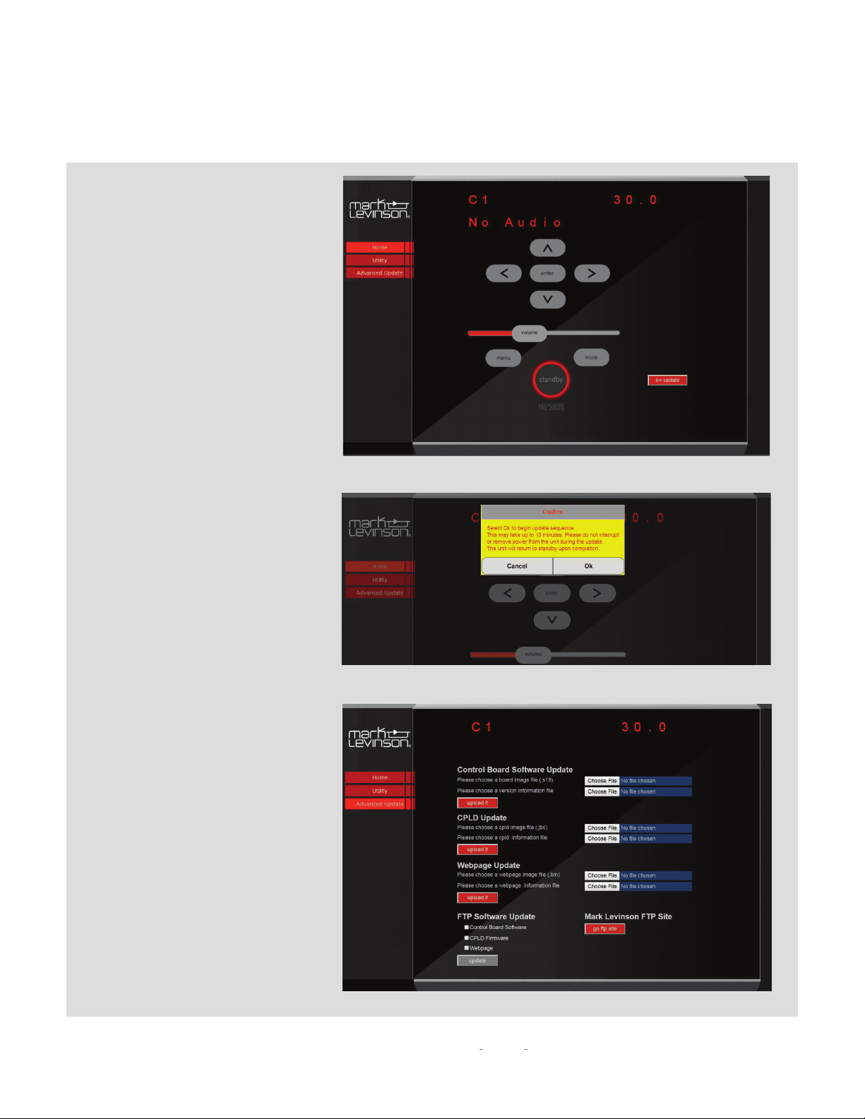
Browser method:
Make sure your unit is connected to a
network with Internet access. Select
the
Home
tab on the screen. Click the
Software Update tab. You will be prompted
for confirmation. Push OK and the unit
will begin the update sequence. Please be
patient and DO NOT INTERRUPT. This can
take up to 15 minutes. The unit will return
to
Standby
Mode when complete. Click
Cancel to go back to the home page.
Advanced Update:
The
Advanced Update
page functions are
used for uploading individual software
files from the FTP server, a USB drive or
your PC’s hard drive. It is highly unlikely
an end user will need to use this page.
This page should be accessed by trained
installers or service professionals.
SETUP

26
N
0
5805 / N
0
5802 INTEGRATED AMPLIFIER / OWNER’S MANUAL
Config:
This menu group allows you to lock, restore, import, or
export Setup configuration settings.
Config Export:
Press Enter to export all setup configuration
information to a thumb drive inserted in the rear panel
USB port. This data can then be used to configure other
N
0
5805 / N
0
5802 units or serve as a backup so you can
quickly reconfigure your unit. Once you have your unit’s
configuration precisely as you would like it, we strongly
recommend you save a Config Export file to a thumb drive in
case an untoward event erases your configuration settings.
Config Import:
Press Enter to import all setup configuration
information from a thumb drive inserted in the rear-panel
USB port.
Config Lock:
Engage the Lock to prevent accidentally changing
the Setup parameters. The factory default setting is Off.
Config Restore:
Restores all N
0
5805 / N
0
5802 parameters to
their factory-default conditions.
Network:
This menu offers access to the following network-
related parameters. They are useful only if you want to connect
your unit to a network to access controls and setup functions
via PC or tablet.
Name:
Displays your N
0
5805’s network name in this format
N5805XXXX (the X’s represent the last four characters of the
unit’s unique MAC address). Use the input select control to
select the character you want to change, and the volume
control to scroll through available characters.
Current Gateway:
Displays the Gateway IP address. This
setting is informational only and does not provide any user
adjustments.
DHCP:
Lets you toggle DHCP mode (network auto-
configuration) On or Off. The factory default behavior is
On. When the mode is set to Off, you can specify static IP
and Subnet addresses for your N
0
5805 / N
0
5802. Selecting
Renew (available only when DHCP is set to On) refreshes
your DHCP configuration, assigning a new IP address to
your N
0
5805 / N
0
5802. This function is often useful when
troubleshooting a network connection.
Current IP:
Shows the IP address currently assigned at the
factory (or by DHCP or manually) to your N
0
5805 / N
0
5802.
Enter this number in the address (URL) line of a browser
connected to the Internet. (This setting is informational only
and does not provide any user adjustments.)
Current Subnet:
Shows the subnet address currently
assigned (by DHCP or manually) to your N
0
5805 / N
0
5802.
(This setting is informational only and does not provide any
user adjustments.)
Trigger:
This setting configures the 12V trigger. NOTE: Using a
trigger input overrides the
Standby
button.
Mode:
These choices determine how the 12V trigger signals
are sent and received.
Normal:
The default setting, appropriate for most other
components.
Pulsed:
Some products (such as some older Mark
Levinson components) require a pulsed trigger signal.
Theater:
Turns on the N
0
5805 and automatically selects
the input configured for SSP mode.
Off:
Disables the Trigger In/Out connections.
Delay:
This setting determines the amount of time after
fully exiting the
Standby
mode that the unit waits to pass
a trigger signal to the trigger output jack. The choices are
0 - 10 seconds, with 0 being the default. NOTE: as it can
take a few seconds for the N
0
5805 / N
0
5802 to enter and exit
Standby
mode, the net trigger delay time will be longer than
the value you select.
Front IR:
This menu allows you to turn the N
0
5805 / N
0
5802’s
front IR receiver on or off. If you plan to use the rear-panel
IR input, you must set the front IR receiver to Off. If you use a
3rd party control via IP or RS232, and do not plan to use IR for
control, we recommend you turn the IR control to Off.
Amplifier Enable:
Selecting Off turns off the amplifier section
of the unit so that it will operate solely as a preamplifier or
headphone amplifier. The default value is On.
SETUPSETUP

27
N
0
5805 / N
0
5802 INTEGRATED AMPLIFIER / OWNER’S MANUAL
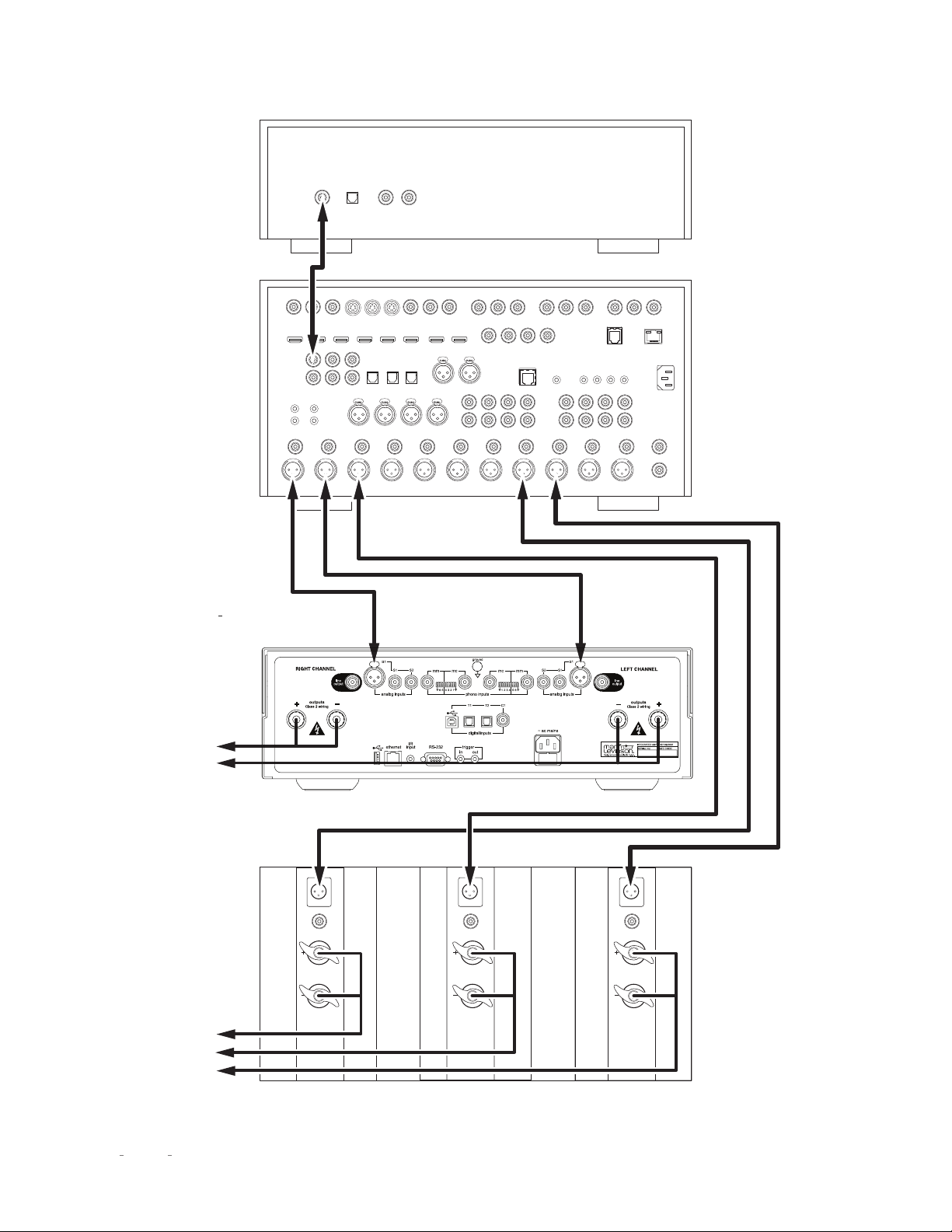
SURROUND SOUND PROCESSOR (SSP) SETUP
(Applies only to the N
0
5805)
The SSP (Surround Sound Processor) mode allows the N
0
5805
to be seamlessly integrated into a multichannel home cinema
system. Any analog input may be designated as the surround
sound processor input by turning this mode ON. When the SSP
mode is activated the N
0
5805’s volume control is deactivated
and the level is fixed at unity gain. This allows the Surround
Sound Processor to control the volume of the Left and Right
speakers powered by the N
0
5805 in unison with the rest of the
system. Room correction EQ and level calibrations performed in
this mode and stored in the surround sound processor will be
maintained unaltered.
CAUTION: Prior to entering SSP mode make sure the volume of
your surround sound processor is all the way down. Gradually
increase volume as desired and perform calibration.
To start, enter the Setup mode and navigate to the analog input
you plan to use for SSP and select On. Connect the N
0
5805 with
a surround-sound processor (see illustration on next page).
1. Make sure the N
0
5805 and all associated components are
powered off and disconnected from electrical outlets.
2. Connect the output connectors on the surround-sound
source component to the input connectors on the
surround-sound processor. For example, if the source
component is a Blu-ray disc player, connect it to the
appropriate input connectors on the surround sound
processor.
3. Connect the front left and right output connectors on the
processor to the desired analog input connectors on the
N
0
5805. For best performance, use balanced connections
whenever possible. NOTE: we recommend renaming the
input you select for SSP operation to a name like “Theater”
or “Movies.”
4. Connect the center, surround, and subwoofer output
connectors on the processor to the appropriate input
connectors on the designated power amplifier(s).
5. Connect the N
0
5805’s speaker outputs to the system’s
front left and right (primary) speakers.
6. Perform a system calibration as per the surround
processor’s instructions.
7. Select the designated Analog input whenever you wish to
listen to multichannel source material.
SETUPSETUP
28
N
0
5805 / N
0
5802 INTEGRATED AMPLIFIER / OWNER’S MANUAL
outputs
inputs
single ended
balanced
outputs
inputs
single ended
balanced
outputs
inputs
single ended
balanced
Analog OutputDigital Output
OpticalCoaxial RL
Composite Video Inputs Component Video Inputs
HDMI OutputsHDMI Inputs
Digital Audio Inputs
Analog Audio In 1Analog Audio In 2
Analog Audio Inputs
ASE/EBU Inputs
Component Video Output
RS-232
Trigger Outputs
IR Input
Link
Surround
Back
Remote Zone
Left
Left
Right
Right
Left
Right
Left
Right
Left
Right
Left
Center
Front
Analog Audio Outputs
Microphone Inputs
12
RR
R
LL
L
3
3
3
12
12
3
Y
Y/G
Pb
Pb/B Pr/R
2
Y/G
Pb/B Pr/R
1
Y/G
Pb/B Pr/R
4
Y/G
Pb/B Pr/R
Pr
1
1
2
2
312
312
312
645
645
4
56
R
L
FL
FR SUB
CTR SL
SR BR
BL
43
Subwoofer 1 Subwoofer 2
Surround
Right
7.1 Channel Input
AC Input
Ethernet
Monitor
Out
S-Video Inputs
SURROUND-SOUND
SOURCE DEVICE
SURROUND-SOUND
PROCESSOR
N
0
5805
INTEGRATED AMPLIFIER
CENTER &
SURROUND
POWER AMPLIFIER
To Front
Left & Right
Speakers
To Center &
Surround
Speakers
SETUP
29
N
0
5805 / N
0
5802 INTEGRATED AMPLIFIER / OWNER’S MANUAL
TROUBLESHOOTING
PROTECTION CIRCUIT FAULTS
If the N
0
5805 / N
0
5802 encounters a potentially damaging condition, its built-in protection circuitry will shut off the amplifier, and its
Front-Panel Display will show one of the error messages listed below. Follow the instructions in the
Solution
column to correct the
condition before attempting to use the N
0
5805 / N
0
5802 again.
ERROR MESSAGE PROBLEM SOLUTION
WARNING: DC DETECTED ON
[LEFT/ RIGHT] CHANNEL
The indicated amplifier channel has detected
DC on the output, which can damage speakers.
Disconnect the AC power cord from the mains
power source. Wait 10 seconds and reattach
the power cord. If the error message does not
clear call your Mark Levinson dealer or Mark
Levinson customer service.
WARNING: OVER TEMP [LEFT/ RIGHT] Indicates the amplifier channel has exceeded
thermal limits.
Wait 10 to 15 minutes to let the unit cool. Press
the
Standby
button. If the error message does
not clear it is likely that your unit does not have
adequate ventilation. Move the amplifier to a
more open location to allow for ventilation.
If that does not correct the problem, call
your Mark Levinson dealer or Mark Levinson
customer service.
WARNING: OVER CURRENT ON
[LEFT/RIGHT] CHANNEL
Indicated amplifier channel has exceeded
current limits.
Disconnect the AC power cord from the mains
power source. Wait 10 seconds and reattach the
power cord. If the error message does not clear
disconnect the power cord again and disconnect
the affected channel’s speaker wire from the
unit. Wait 10 seconds and reattach the AC power
cord. If the error message does not clear call
your Mark Levinson dealer or Mark Levinson
customer service.
If your unit is connected to a home network, use a PC or tablet to access the N
0
5805 / N
0
5802’s GUI via a web browser. On the
right side of the Utility page, you will see a red bell icon with various status indicators, including operating temperature (shown in
degrees Celsius). Note the indicators and open the “Fault History” file. This data may help you or a technician diagnose any amplifier
malfunctions or adverse conditions.
TROUBLESHOOTING

30
N
0
5805 / N
0
5802 INTEGRATED AMPLIFIER / OWNER’S MANUAL
NO POWER
Examine the power cord to ensure that it is connected to both the AC mains connector and a working, un-switched electrical outlet.
Check the mains fuse accessible on the rear panel mains outlet.
Examine the electrical circuit breaker to ensure that power is being supplied to the electrical outlet to which the N
0
5805 / N
0
5802 is connected.
Make sure the N
0
5805 / N
0
5802 is not in
Standby
mode. The front-panel standby LED illuminates fully and continually when the N
0
5805 / N
0
5802 is
On. The LED flashes slowly when the N
0
5805 / N
0
5802 is in
Standby
mode.
REMOTE CONTROL DOES NOT OPERATE
Eliminate obstructions between the remote control IR transmitter and the IR receiver on the N
0
5805 / N
0
5802’s front-panel display.
Check the menu to make sure the front panel IR was not disabled.
Make sure the rear-panel IR input connector is not being used.
Make sure the remote control is positioned within 17 feet (5m) and within a 45-degree angle of the N
0
5805 / N
0
5802’s front panel.
Make sure the IR receiver on the N
0
5805 / N
0
5802's front-panel display is not exposed to intense sunlight, halogen light, or fluorescent light. This
can cause IR reception to become unreliable.
Replace the remote control batteries.
NO SIGNAL AT THE SPEAKER OR LINE OUTPUTS
Examine all audio cables to ensure a reliable connection between the N
0
5805 / N
0
5802 and all associated components.
Examine the speaker cables to ensure a reliable connection between the N
0
5805 / N
0
5802 and the speakers.
Make sure that the connected speakers are working by connecting one of them to another amplifier (if available).
Make sure the volume is set to an audible level (start at 30 and move slowly up from there).
Make sure the mute is deactivated. The word “Mute” appears on the front panel display when in Mute mode. Push the Mute button to return to
normal operation.
Make sure the Offset setting for the selected input is not reducing the volume to an inaudible level. See Setup/Input for more information.
Make sure all associated components are connected to working electrical outlets and powered On.
Make sure the source device connected to the selected N
0
5805 / N
0
5802 input is producing an output signal.
“MISSING” INPUT
Make sure the Name parameter for the selected input has not been set to Disabled in the
Setup
menu. (Refer to Setup/Inputs/ on page 18 for more
information.)
TROUBLESHOOTING

31
N
0
5805 / N
0
5802 INTEGRATED AMPLIFIER / OWNER’S MANUAL
AUDIO HAS A HUMMING SOUND
Disconnect components one at a time to isolate the problem.
Once you have identified the problematic component, make sure it is properly grounded and connected to the same electrical circuit as the
N
0
5805 / N
0
5802.
VOLUME CAN’T BE SET TO MAXIMUM
You have the option of establishing a maximum volume level in the
Setup
menu. If this option is set, it can prevent the N
0
5805 / N
0
5802 from
reaching the maximum volume level of 80.0. (Refer to Setup/Volume/ MaxVol on page 21 for more information.)
FRONT-PANEL DISPLAY NOT WORKING
Press any remote or front panel button to restore the display from the off mode. (Refer to Setup/Display/Auto-Off on page 22 for more information.)
NO CONNECTIVITY VIA ETHERNET
Verify that an Ethernet cable is correctly connected between the router, switch or hub and the N
0
5805 / N
0
5802.
Verify the age of the router, switch or hub. If the router, switch or hub is more than ten years old, there may be a communication issue with the
N
0
5805 / N
0
5802. Power cycle the unit and use a newer router, switch or hub between the network and the N
0
5805 / N
0
5802.
IF ALL ELSE FAILS…
Power cycle the N
0
5805 / N
0
5802 by unplugging the power cord, waiting at least 10 seconds and reconnecting the power cord.
Restore factory-default settings (see Setup/Advanced/Config/Restore on page 26).
Contact your authorized Mark Levinson dealer.
Contact Mark Levinson Customer Service at 888-691-4171 or www.marklevinson.com.
TROUBLESHOOTING

32
N
0
5805 / N
0
5802 INTEGRATED AMPLIFIER / OWNER’S MANUAL
SPECIFICATIONS
ANALOG LINE STAGE (№5805 ONLY)
Line Input Impedance: Balanced (XLR): 20kΩ; Single-ended (RCA): 10kΩ
Volume Control: Balanced; voltage mode; digitally-controlled resistor network
Gain: 8.5dB maximum
Output Impedance: 55Ω
Output Overload: >4.5V RMS
Frequency Response: 20Hz to 20kHz, ±0.03dB; <2Hz to 210kHz, +0.1/–3dB (At unity gain volume setting)
Total Harmonic Distortion: <0.01%,1kHz; <0.03%,20 kHz; 2V RMS output (At unity gain volume setting)
Signal-To-Noise Ratio: >96dB (20Hz to 20kHz, A-weighted); >93dB (20Hz to 20kHz, wideband, unweighted)
(Referred to 2V RMS output, unity gain volume setting)
Input Sensitivity: 53mV RMS at line input for 2.83V RMS at speaker output, maximum volume setting
System Gain: 34.5dB, line input to speaker output, maximum volume setting
PHONO STAGE (№5805 ONLY)
Riaa Frequency Response: 20Hz to 20kHz, ±0.3dB
Infrasonic Filter: Selectable; 20Hz, 1st order (6dB/octave)
MOVING-MAGNET MODE
Input Resistance: 47kΩ
Input Capacitance: Selectable; 20, 70, 120, 170pF
Gain: 39dB at 1kHz
Total Harmonic Distortion: <0.01%, 1kHz, 2V RMS output; <0.05%, 20kHz, 2V RMS output
Signal-To-Noise Ratio: >90dB (20Hz to 20kHz A-weighted, referred to 2V RMS output);
>78dB (20Hz to 20kHz, wideband, unweighted, referred to 2V RMS output)
Maximum Input Level: >190mV at 1kHz; >1.6V at 20kHz
SPECIFICATIONS

33
N
0
5805 / N
0
5802 INTEGRATED AMPLIFIER / OWNER’S MANUAL
MOVING-COIL MODE
Input Resistance: Selectable, 37Ω to 1000Ω
Gain: 69dB at 1kHz
Total Harmonic Distortion: <0.01%, 1kHz, 2V RMS output; <0.06%, 20kHz, 2V RMS output
Signal-To-Noise Ratio: >71dB (20Hz to 20kHz A-weighted, referred to 2V RMS output);
>66dB (20Hz to 20kHz, wideband, unweighted, referred to 2V RMS output)
Maximum Input Level: >6.5mV at 1kHz; >19mV at 20kHz
DIGITAL-TO-ANALOG CONVERTER STAGE
Output Voltage: 5.7V RMS at maximum volume/full scale (0dBFS)
Frequency Response: 20Hz to 20kHz, +0/–0.05dB (44.1kHz/16 bit signal); 20Hz to 20kHz, +0/–0.02dB (192kHz/24 bit signal)
Total Harmonic Distortion: <0.0025%, 20Hz to 20kHz,at 3V RMS output (192kHz/24 bit signal);
<0.003%, 20Hz to 20kHz, at 3V RMS output (44.1kHz/16 bit signal);
<0.006%, 90kHz, at 3V RMS output (192kHz/24 bit signal)
Signal-To-Noise Ratio: >100dB (20Hz to 20 kHz, 192kHz/24 bit signal, A-weighted);
>98dB (20Hz to 20 kHz, 192kHz/24 bit signal, wideband, unweighted);
>94dB (20Hz to 20 kHz, 44.1kHz/16 bit signal, A-weighted);
>92dB (20Hz to 20 kHz, 44.1kHz/16 bit signal, wideband, unweighted)
Referred to 3VRMS output
Sample Rates/Bit Depth: PCM: 32, 44.1, 48, 88.2, 96, 176.4, 192, 352.8, or 384kHz; up to 32 bits; DSD: Native or DoP; single,
double, or quad speed (2.8, 5.6, or 11.2MHz)
Digital Processing: Full MQA decoding; PCM: Seven user-selectable digital filter settings;
user-selectable up-sampling to 352.8/384kHz; DSD: Four user-selectable digital filter settings
HEADPHONE OUTPUT
Total Harmonic Distortion: <0.04%, 20Hz and 1kHz, 2V RMS output, 30Ω load; <0.10%, 20kHz, 2V RMS output, 30Ω load
Output Overload: >3.3V RMS, 30Ω load
Signal-To-Noise Ratio: >91dB (20Hz to 20kHz, A-weighted, referred to 2V RMS output); >87dB (20Hz to 20kHz, wideband,
unweighted, referred to 2V RMS output
Output Impedance: <2.5Ω, 20Hz to 20kHz
SPECIFICATIONS

34
N
0
5805 / N
0
5802 INTEGRATED AMPLIFIER / OWNER’S MANUAL
AMPLIFIER SECTION
Frequency Response: <2Hz to 20kHz, +0/–0.2 dB; <2Hz to 100kHz, +0/–3dB
Signal-To-Noise Ratio: >103dB (20Hz to 20 kHz, A-weighted); >100dB (20Hz to 20 kHz, wideband, unweighted)
Total Harmonic Distortion + Noise: <0.035% at 1kHz, 125W, 8Ω; <0.18% at 20kHz, 125W, 8Ω
Output Power: 125W RMS per channel at 8Ω, 20Hz to 20kHz
Output Impedance: <0.098Ω, 20Hz to 10kHz; <0.11Ω at 20kHz
Damping Factor: >82, 20Hz to 10kHz; >72 at 20kHz (All referred to 8Ω)
GENERAL
Analog Input Connectors
(№5805 Only):
1 pair balanced line-level inputs (XLR); 2 pairs single-ended line-level inputs (RCA); 1 pair single-ended
moving-coil phono inputs (RCA); 1 pair single-ended moving-magnet phono inputs (RCA)
Digital Audio Connectors: 2 optical digital inputs (Toslink); 1 asynchronous USB digital input (USB-B); №5805: 1 coaxial digital
S/PDIF input (RCA); №5802: 2 coaxial digital S/PDIF input (RCA); №5802: 1 balanced digital AES/EBU
input (XLR)
Output Connectors: 1 pair single-ended line-level outputs (RCA); 2 pairs loudspeaker outputs (High-current binding posts with
banana sockets; accept spade lugs with ¼”/6.3mm spacing up to ⅛”/3mm thick)
Control Connectors: 1 RS-232 port (DB9 connector); 1 IR input (⅛”/3.5mm phone jack); 1 programmable 12V DC trigger output
(⅛”/3.5mm phone jack), 100mA maximum; 1 programmable 12V DC trigger input (⅛”/3.5mm phone jack);
1 Ethernet port (RJ-45 connector)
Mains Voltage: 100VAC, 115VAC, or 230VAC, factory set
Power Consumption:
Standby
, “Green” mode: <0.4W;
Standby
, “Power Save” mode: 7W; №5805:
Standby
, “Normal” mode: 70W;
№5802:
Standby
, “Normal” mode: 45W; №5805: Power on, quiescent: 120W;
№5802: Power on, quiescent: 95W; №5805: Power on, both channels at ⅛ rated power: 240W;
№5802: Power on, both channels at ⅛ rated power: 215W; Power on, maximum: 500W
Dimensions/Weight (Unit): Height: 5.72”/145mm; Height without feet: 5.25”/133mm; Width: 17.25”/438mm; Depth: 19.98”/507mm;
Weight (№5805): 62 lbs/28.1kg; Weight (№5802): 61 lbs/27.6kg
Dimensions/Weight (With Packaging): Height: 13.0”/330mm; Width: 24.0”/610mm; Depth: 28.0”/711mm; Weight (№5805): 73 lbs/33.0kg;
Weight (№5802): 72 lbs/32.6kg
SPECIFICATIONS


HARMAN International Industries, Incorporated
8500 Balboa Boulevard
Northridge, CA 91329 USA
© 2019 HARMAN International Industries, Incorporated. All rights reserved.
Mark Levinson is a registered trademark of HARMAN International Industries, Incorporated.
Other company and product names may be trademarks of the respective companies with which they
are associated.
"MQA" is a trade mark of MQA Limited.
This document should not be construed as a commitment on the part of HARMAN International
Industries, Incorporated. The information it contains, as well as the features, specifications and
appearance of the product, is subject to change without notice. HARMAN International Industries,
Incorporated, assumes no responsibility for errors that may appear within this document
For customer service and product shipment information, refer to our Website: www.marklevinson.com
Part No. 070-90062 rev. A.1 www.marklevinson.com