Loading ...
Loading ...
Loading ...
Installation Instructions
15
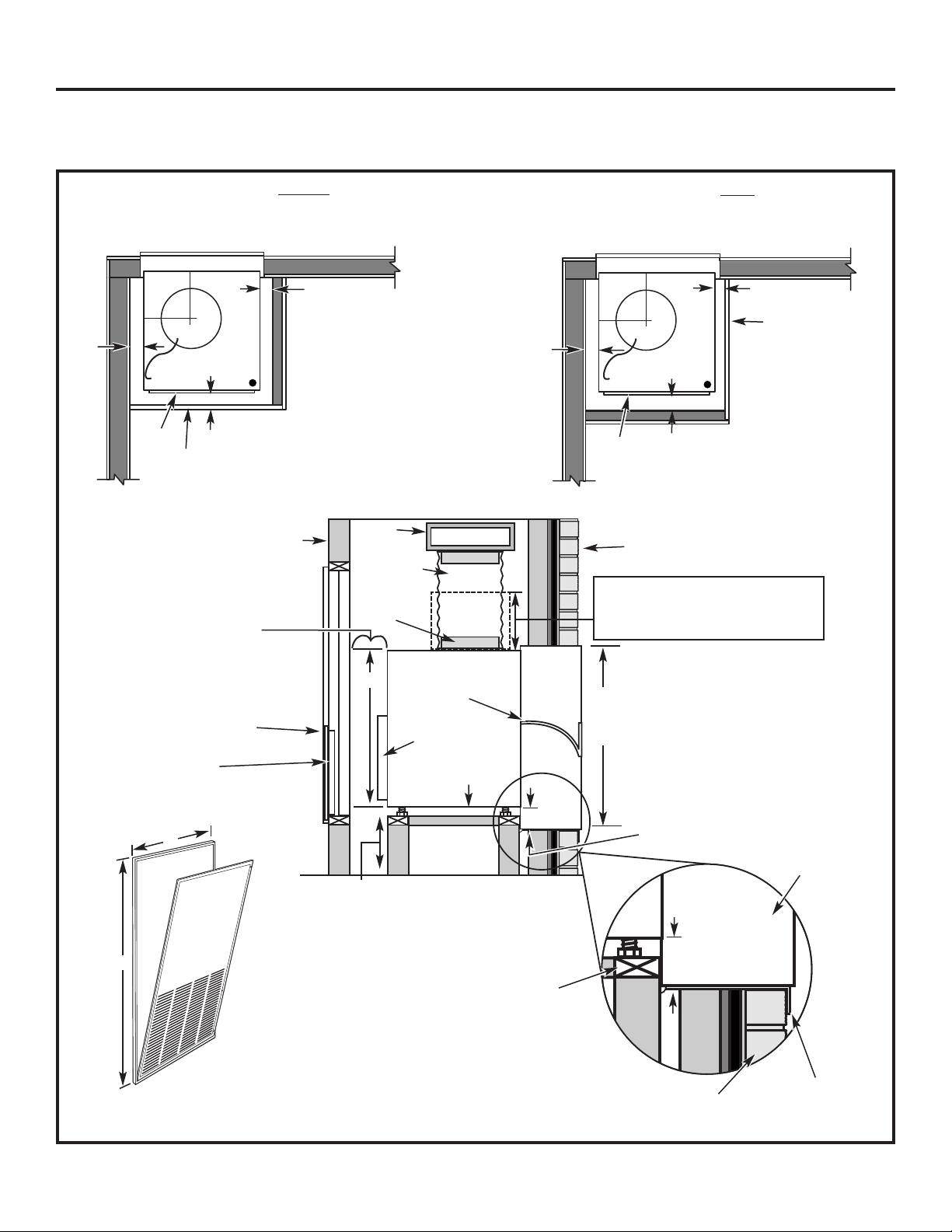
TYPICAL UTILITY CLOSET AND DIMENSIONS
(FOR REFERENCE ONLY)
Side View
Top View
Architectural Louver
10″
duct
Door/access panel
3″ min.
5″ min.
Unit front
3″
min.
14″ min. – Required only if optional Hydronic
Heating Kit (RAVHW1, RAVHW2, RAVHW3) is to
be installed. Clearance for installation should be
taken into consideration if this kit is to be used.
Exterior/Outside
Outside wall
Wall
plenum
Inside wall
Air discharge
outlet
Rigid
ductwork
Flexible or
rigid duct
Wall plenum
divider
31″
Option 1
Access panel with
return air grille
Option 2
Return air grille
Filter bracket
Secure platform
to the floor
Platform: 23
1
⁄4″ x23
1
⁄4″ square
Min. load capacity: 175 lbs.
• 4″ min. from front of case – Unit
installed through FRONT of case.
• 5″ min. from front of case – Unit
installed through SIDE of case.
• 3″ min. from two sides of case.
Plenum
cutout
32
1
⁄4″ H
x 20″ W
Drain fittings
3
⁄4″
Outside wall
Platform
Wall plenum
Field supplied
outer flashing
10″
11
1
⁄2″
A
B
A Minimum recommended access door width: 30″
B Minimum recommended access door height: 50″
UNIT INSTALLED THROUGH SIDE OF CASE
Top View
Architectural Louver
10″
duct
Door/access panel
3″ min.
4″ min.
Unit
front
3″
min.
10″
11
1
⁄2″
UNIT INSTALLED THROUGH FRONT OF CASE
Bottom of case approx. 2″
above bottom of plenum
8″ min.
for drain
access
Bottom of case approx. 2″
above bottom of plenum
Unit
Loading ...
Loading ...
Loading ...