(BGE-103A)
Owner’s Manual 3
ENGLISH
Safety Precautions
Safety Precautions
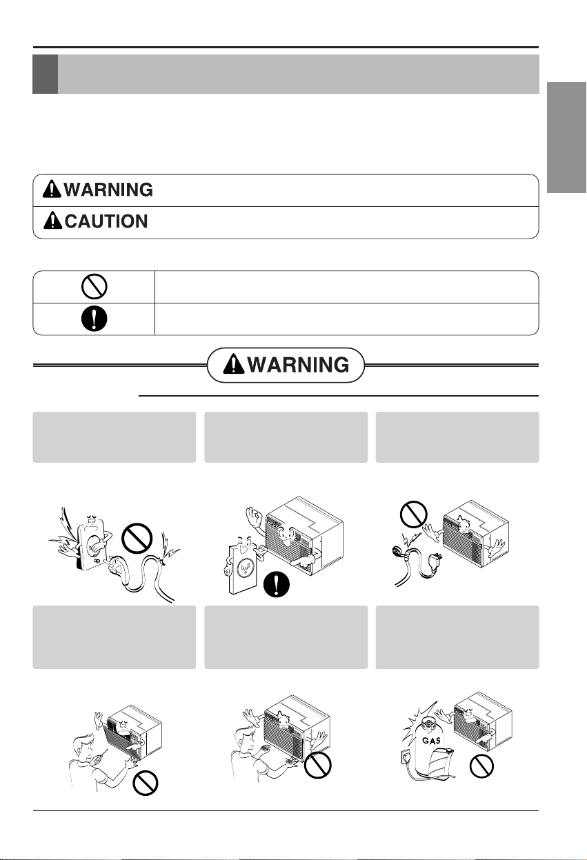
To prevent injury to the user or other people and property damage, the following instructions
must be followed.
■ Incorrect operation due to ignoring instruction will cause harm or damage. The seriousness
is classified by the following indications.
■ Meanings of symbols used in this manual are as shown below.
This symbol indicates the possibility of death or serious injury.
This symbol indicates the possibility of injury or damage to properties only.
Be sure not to do.
Be sure to follow the instruction.
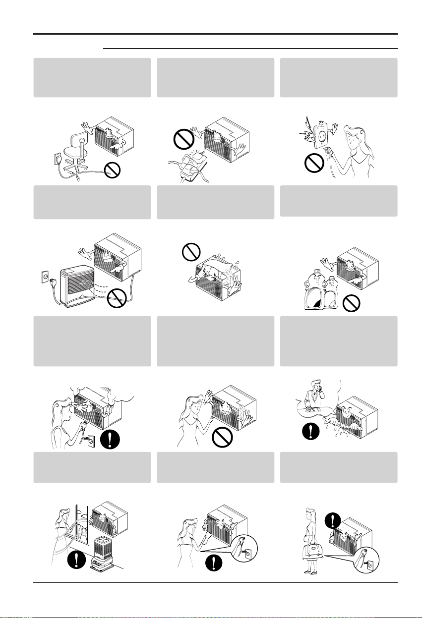
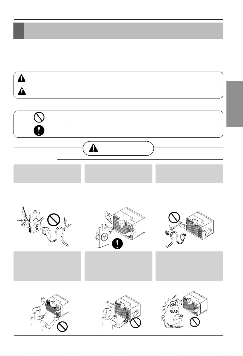
■ Installation
Don’t use a power cord, a
plug or a loose socket which
is damaged.
• Otherwise, it may cause a
fire or electrical shock.
Always plug into a grounded
outlet.
• Otherwise, it may cause a
fire or electrical shock.
Do not modify or extend the
power cord length.
• It will cause electric shock or
fire due to heat generation.
M
O
D
E
T
I
M
E
R
P
O
W
E
R
F
A
N
S
P
E
E
D
Fan
H
eat
E
n
e
r
g
y
S
a
v
e
r
Cool
T
i
m
e
r
T
E
M
P
'
F
F
1
L
O
W
F
2
H
I
G
H
M
O
D
E
T
I
M
E
R
P
O
W
E
R
FAN
S
P
EE
D
F
a
n
H
e
a
t
E
n
e
r
g
y
S
a
v
e
r
C
o
o
l
T
i
m
e
r
T
E
M
P
'
F
F
1
L
O
W
F
2
H
I
G
H
Do not disassemble or
modify products.
• It may cause failure and
electric shock.
Be caution when unpacking
and installing.
• Sharp edges may cause
injury.
Do not use the power cord near
flammable gas or combustibles
such as gasoline, benzene,
thinner, etc.
• It may cause explosion or
fire.
M
O
D
E
T
I
M
E
R
P
O
W
E
R
F
A
N
S
P
E
E
D
F
a
n
H
e
a
t
E
n
erg
y
S
av
e
r
C
o
o
l
T
i
m
e
r
T
E
M
P
'
F
F
1
L
O
W
F
2
H
IG
H
M
O
D
E
T
I
M
E
R
P
O
W
E
R
F
A
N
S
P
E
E
D
Fa
n
H
e
at
E
n
e
r
g
y
S
a
v
e
r
C
o
ol
T
im
e
r
T
E
M
P
'
F
F
1
L
O
W
F
2
H
I
G
H
Gasolin
M
O
D
E
T
I
M
E
R
P
O
W
E
R
F
A
N
S
P
E
E
D
F
a
n
H
e
a
t
E
n
e
r
g
y
S
a
v
e
r
C
o
o
l
T
i
m
e
r
T
EM
P
'
F
F
1
L
O
W
F
2
H
I
G
H
2 Room Air Conditioner
FOR YOUR RECORDS
Write the model and serial numbers here:
Model #
Serial #
You can find them on a label on the side of each unit.
Dealer's Name
Date Purchased
■ Staple your receipt to this page in the event you need it
to prove date of purchase or for warranty issues.
READ THIS MANUAL
Inside you will find many helpful hints on how to use and
maintain your air conditioner properly. Just a little preventive
care on your part can save you a great deal of time and
money over the life of your air conditioner.
You'll find many answers to common problems in the chart
of troubleshooting tips. If you review our chart of
Troubleshooting Tips first,youmaynotneedtocallfor
service at all.
PRECAUTION
• Contact the authorized service technician for repair
or maintenance of this unit.
• Contact the installer for installation of this unit.
• The air conditioner is not intended for use by young
children or invalids without supervision.
• Young children should be supervised to ensure that
they do not play with the air conditioner.
• When the power cord is to be replaced, replacement
work shall be performed by authorized personnel only
using only genuine replacement parts.
• Installation work must be performed in accordance
with the National Electric Code by qualified and
authorized personnel only.
Safety Precautions ..........................3
Prior to Operation ...........................7
Introduction .....................................8
Electrical Safety .............................9
Installation ....................................11
Operating Instructions .................18
Maintenance and Service ............21
Window-Type Air Conditioner Owner’s Manual
TABLE OF CONTENTS
4 Room Air Conditioner
Safety Precautions
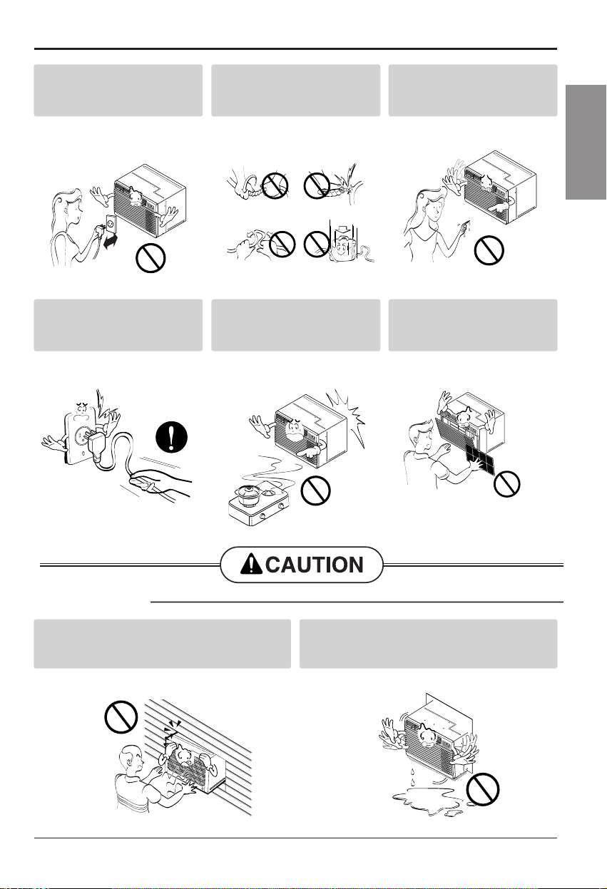
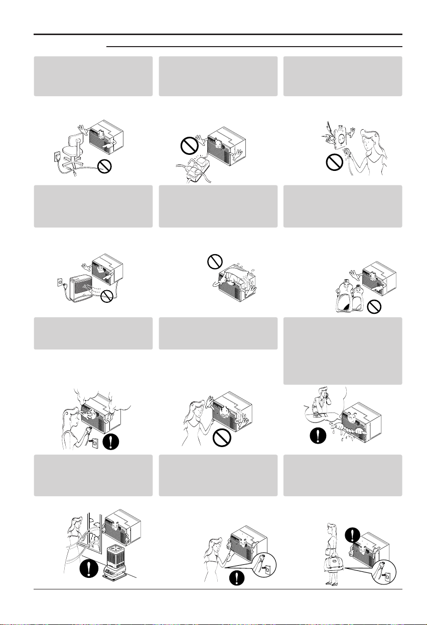
■ Operation
Do not place the power cord
near a heater.
• It may cause fire and electric
shock.
Do not allow water to run
into electric parts.
• It will cause failure of machine
or electric shock.
Use a soft cloth to clean. Do
not use wax, thinner, or a
strong detergent.
• The appearance of the air
conditioner may deteriorate,
change color, or develop
surface flaws.
M
O
D
E
T
I
M
E
R
P
O
W
E
R
F
A
N
S
P
E
E
D
F
a
n
H
e
a
t
E
n
e
r
g
y
S
a
v
e
r
C
o
o
l
T
i
m
e
r
T
E
M
P
'
F
F
1
L
O
W
F
2
H
I
G
H
M
O
D
E
T
I
M
E
R
P
O
W
E
R
F
A
N
S
P
E
E
D
F
a
n
H
e
a
t
E
n
e
r
g
y
S
a
v
e
r
C
o
o
l
T
i
m
e
r
T
E
M
P
'
F
F
1
L
O
W
F
2
H
I
G
H
Wax
Thinner
M
ODE
T
IM
E
R
P
OW
ER
F
AN
SP
E
ED
F
a
n
H
e
at
En
e
r
g
y
S
a
v
e
r
C
o
ol
T
im
e
r
T
E
M
P
'
F
F
1
L
O
W
F
2
H
I
G
H
Ventilate the room well when
using this appliance
together with a stove, etc.
• An oxygen shortage may
occur.
Turn off the power and
breaker firstly when
cleansing the unit.
• Since the fan rotates at high
speed during operation, it may
cause injury.
Turn off the main power
switch when not using it for
alongtime.
• Prevent accidental startup and
the possibility of injury.
M
O
D
E
T
I
M
E
R
P
O
W
E
R
F
A
N
S
P
E
E
D
F
a
n
H
e
a
t
E
n
e
r
g
y
S
a
v
e
r
C
o
o
l
T
i
m
e
r
T
E
M
P
'
F
F
1
L
O
W
F
2
H
I
G
H
M
O
D
E
T
I
M
E
R
P
O
W
E
R
F
A
N
S
P
E
E
D
F
a
n
H
e
a
t
E
n
e
r
g
y
S
a
v
e
r
C
o
o
l
T
i
m
e
r
T
E
M
P
'
F
F
1
L
O
W
F
2
H
I
G
H
M
O
D
E
T
I
M
E
R
P
O
W
E
R
F
A
N
S
P
E
E
D
F
a
n
H
e
a
t
E
n
e
r
g
y
S
a
v
e
r
C
o
ol
T
i
m
e
r
T
E
M
P
'
F
F
1
L
O
W
F
2
H
I
G
H
Unplug the unit if strange
sounds, odors, or smoke
come from it.
• Otherwise it may cause fire
and electric shock accident.
Do not open the suction
inlet grill of the product
during operation.
• Otherwise, it may electrical
shock and failure.
If water enters the product, turn
off the the power switch of the
main body of appliance. Contact
service center after taking the
power-plug out from the socket.
M
O
D
E
T
I
M
E
R
P
O
W
E
R
F
AN
SPEE
D
F
a
n
H
e
a
t
E
n
e
r
g
y
S
a
v
e
r
C
o
o
l
T
i
m
e
r
T
E
M
P
'
F
F
1
L
O
W
F
2
H
I
G
H
M
O
D
E
T
I
M
E
R
P
O
W
E
R
F
A
N
S
P
E
E
D
F
a
n
H
e
a
t
E
n
e
r
g
y
S
a
v
e
r
C
o
o
l
T
i
m
e
r
T
E
M
P
'
F
F
1
L
O
W
F
2
H
I
G
H
M
O
D
E
T
I
M
E
R
P
O
W
E
R
F
A
N
S
P
E
E
D
F
a
n
H
e
a
t
E
n
e
r
g
y
S
a
v
e
r
C
o
o
l
T
i
m
e
r
T
E
M
P
'
F
F
1
L
O
W
F
2
H
IG
H
M
O
D
E
T
I
M
E
R
P
O
W
E
R
F
A
N
S
P
E
E
D
F
a
n
H
e
a
t
E
n
e
r
g
y
S
a
v
e
r
C
o
o
l
T
i
m
e
r
T
E
M
P
'
F
F
1
L
O
W
F
2
H
I
G
H
MO
DE
TI
ME
R
PO
WE
R
F
A
N
S
P
E
E
D
F
a
n
H
e
a
t
E
n
e
r
g
y
S
a
v
e
r
C
o
o
l
T
i
m
e
r
T
E
M
P
'
F
F
1
L
O
W
F
2
H
I
G
H
Do not place heavy object
on the power cord and take
care so that the cord should
not be pressed.
• There is danger of fire or
electric shock.
Do not share the outlet with
other appliances.
• It will cause electric shock or
fire due to heat generation.
Take the power plug out if
necessary, holding the head
of the plug and do not touch
it with wet hands.
• Otherwise, it may cause a
fire or electrical shock.
Owner’s Manual 5
ENGLISH
Safety Precautions
■ Installation
Do not operate or stop the
unit by inserting or pulling
out the power plug.
• It will cause electric shock or
fire due to heat generation.
Do not damage or use an
unspecified power cord.
• It will cause electric shock or
fire.
Do not operate with wet
hands or in damp
environment.
• It will cause electric shock.
M
O
D
E
T
I
M
E
R
P
O
W
E
R
F
A
N
S
P
E
E
D
Fa
n
H
e
at
E
n
e
r
g
y
S
a
v
e
r
C
o
o
l
T
im
e
r
T
E
M
P
'
F
F
1 L
OW
F
2
HIG
H
M
O
D
E
T
I
M
E
R
P
O
W
E
R
F
A
N
S
P
E
E
D
Fa
n
H
e
a
t
E
n
e
r
g
y
S
a
v
e
r
C
o
o
l
T
im
e
r
T
E
M
P
'
F
F
1 L
O
W
F
2 H
IG
H
Hold the plug by the head
when taking it out.
• It may cause electric shock
and damage.
When gas leaks, open the
window for ventilation
before operating the unit.
• Otherwise, it may cause
explosion, and a fire.
Never touch the metal parts
of the unit when removing
the filter.
• They are sharp and may
cause injury.
M
O
D
E
T
I
M
E
R
P
O
W
E
R
F
A
N
S
P
E
E
D
F
a
n
H
e
a
t
E
n
e
r
g
y
S
a
v
e
r
C
o
o
l
T
im
e
r
T
E
M
P
'
F
F
1 L
OW
F
2
H
I
G
H
M
O
D
E
T
I
M
E
R
P
O
W
E
R
F
A
N
S
P
E
E
D
F
a
n
H
e
a
t
E
n
e
r
g
y
S
a
v
e
r
C
o
o
l
Ti
m
e
r
T
E
M
P
'
F
F1
LO
W
F
2 H
IG
H
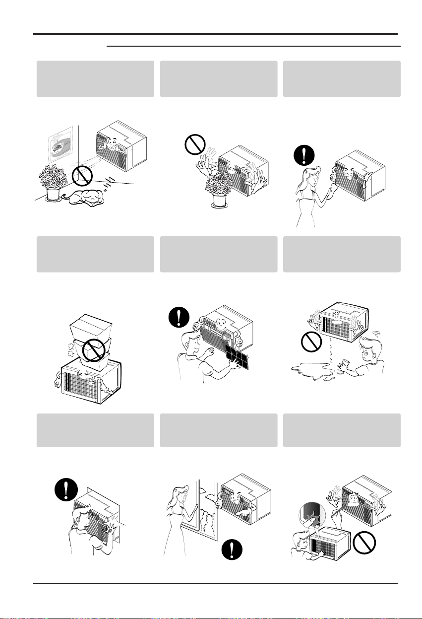
Install the product so that the noise or hot
wind from the outdoor unit may not cause
any damage to the neighbors.
• Otherwise, it may cause dispute with the
neighbors.
Keep level parallel in installing the product.
• Otherwise, it may cause vibration or water
leakage.
M
O
D
E
T
I
M
E
R
P
O
W
E
R
F
A
N
S
P
E
E
D
Fa
n
H
eat
E
n
e
r
g
y
S
a
v
e
r
Coo
l
Ti
m
e
r
TE
M
P
'
F
F
1
L
O
W
F
2
H
I
G
H
6 Room Air Conditioner
Safety Precautions
■ Operation
M
O
D
E
T
IME
R
P
O
W
E
R
F
A
N
S
P
E
E
D
F
a
n
H
e
a
t
E
n
er
g
y
S
a
v
e
r
C
o
o
l
T
im
e
r
T
E
M
P
'
F
F
1
L
O
W
F
2
H
I
G
H
M
O
D
E
T
I
M
E
R
P
O
W
E
R
F
A
N
S
P
E
E
D
F
a
n
H
e
a
t
E
n
e
r
g
y
S
a
v
e
r
C
o
o
l
T
i
m
e
r
T
E
M
P
'
F
F1
L
O
W
F
2
H
IG
H
M
O
D
E
T
I
M
E
R
P
O
W
E
R
F
A
N
S
P
E
E
D
F
a
n
H
e
a
t
E
n
e
r
g
y
S
a
v
e
r
C
o
o
l
T
i
m
e
r
T
E
M
P
'
F
F
1
L
O
W
F
2
H
I
G
H
Be cautious not to touch the
sharp edges when
installing.
• It may cause injury.
Avoid excessive cooling and
perform ventilation
sometimes.
• Otherwise, it may do harm
to your health.
Do not insert the hands or
bars through the air inlet or
outlet during operation.
• Otherwise, it may cause
personal injury.
Do not put a pet or house
plant where it will be
exposedtodirectairflow.
• It may cause injury.
Do not block the inlet or
outlet of air flow.
• It may cause product failure.
Useasoftclothtoclean.Do
not use wax, thinner, or a
strong detergent.
• The appearance of the air
conditioner may deteriorate,
change color, or develop
surface flaws.
M
O
D
E
T
I
M
E
R
P
O
W
E
R
F
A
N
S
P
E
E
D
F
a
n
H
e
at
E
n
e
r
g
y
S
a
v
e
r
Co
ol
T
im
e
r
T
E
M
P
'
F
F1 L
OW
F
2
HIG
H
M
O
D
E
T
I
M
E
R
P
O
W
E
R
F
A
N
S
P
E
E
D
F
a
n
H
e
a
t
E
n
e
r
g
y
S
a
v
e
r
C
o
o
l
T
i
m
e
r
T
E
M
P
'
F
F1
LO
W
F
2 H
IGH
M
O
D
E
T
I
M
E
R
P
O
W
E
R
F
A
N
S
P
E
E
D
F
a
n
H
e
at
E
n
e
r
g
y
S
a
v
e
r
Co
ol
T
im
er
T
E
M
P
'
F
F
1
L
OW
F
2
H
IG
H
Do not step on the
indoor/outdoor unit and do
notputanythingonit.
• It may cause an injury
through dropping of the unit
or falling down.
Always insert the filter
securely.
Clean it every two weeks.
• Operation without filters will
cause failure.
Do not drink water drained
from air conditioner.
• It contains containments and
will make you sick.
M
O
D
E
T
I
M
E
R
P
O
W
E
R
F
A
N
S
P
E
E
D
F
an
H
e
a
t
E
n
e
r
g
y
S
a
v
e
r
C
o
ol
T
i
m
e
r
T
E
M
P
'
F
F
1 L
OW
F2
H
IG
H

Owner’s Manual 7
ENGLISH
Prior to Operation
1. Contact an installation specialist for installation.
2. Plug in the power plug properly.
3. Use a dedicated circuit.
4. Do not use an extension cord.
5. Do not start/stop operation by plugging/unplugging the power cord.
6. If the cord/plug is damaged, replace it with only an authorized replacement
part.
1. Being exposed to direct airflow for an extended period of time could be
hazardous to your health. Do not expose occupants, pets, or plants to direct
airflow for extended periods of time.
2. Due to the possibility of oxygen deficiency, ventilate the room when used
together with stoves or other heating devices.
3. Do not use this air conditioner for non-specified special purposes (e.g.
preserving precision devices, food, pets, plants, and art objects). Such usage
could damage the items.
1. Do not touch the metal parts of the unit when removing the filter. Injuries can
occur when handling sharp metal edges.
2. Do not use water to clean inside the air conditioner. Exposure to water can
destroy the insulation, leading to possible electric shock.
3. When cleaning the unit, first make sure that the power and breaker are turned
off. The fan rotates at a very high speed during operation. There is a
possibility of injury if the unit’s power is accidentally triggered on while
cleaning inner parts of the unit.
For repair and maintenance, contact your authorized service dealer.
Prior to Operation
Preparing for Operation
Usage
Cleaning and Maintenance
Service
8 Room Air Conditioner
Introduction
Introduction
This symbol alerts you to the risk of electric shock.
This symbol alerts you to hazards that could cause harm to
the air conditioner.
This symbol indicates special notes.
NOTICE
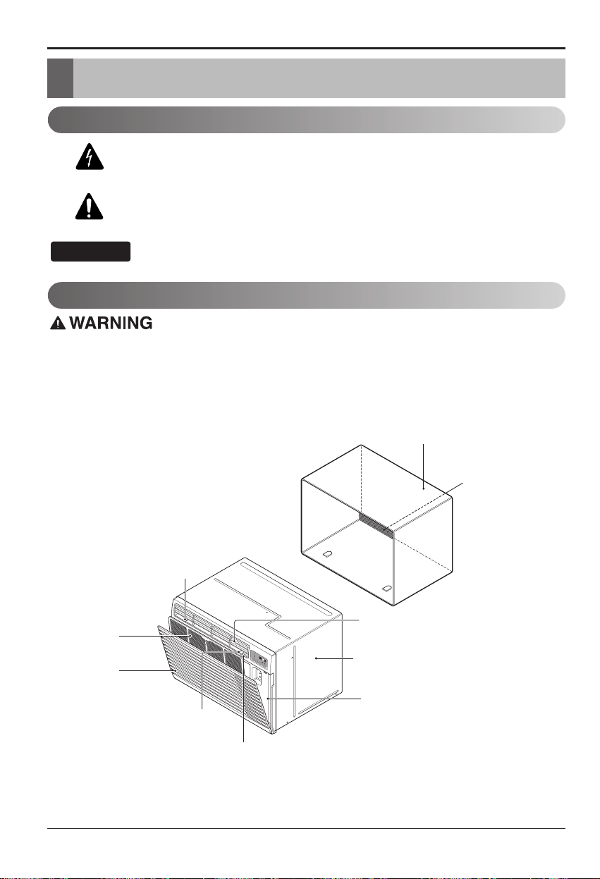
CABINET
FRONT GRILLE
INLET GRILLE
(Air Intake)
AIR FILTER
HORIZONTAL AIR DEFLECTOR
(Vertical Louver)
VENT CONTROL
VERTICAL AIR DEFLECTOR
(Horizontal Louver)
AIR DISCHARGE
SLEEVE ASSEMBLY
(Including Aluminum Rear grille)
THE SLEEVE AND THE REAR GRILLE
(optionally supplied with your unit)
THE UNIT
REAR GRILLE
(Aluminum Rear grille)
M
O
D
E
TI
M
ER
PO
W
ER
F
AN
S
P
EED
F
a
n
H
e
a
t
E
n
e
r
g
y
S
a
v
e
r
C
o
o
l
T
i
m
e
r
T
E
M
P
'
F
F
1
L
O
W
F
2
H
I
G
H
Symbols Used in this Manual
Features
This appliance should be installed in accordance with the National Electric Code.
Owner’s Manual 9
ENGLISH
Electrical Safety
Electrical Safety
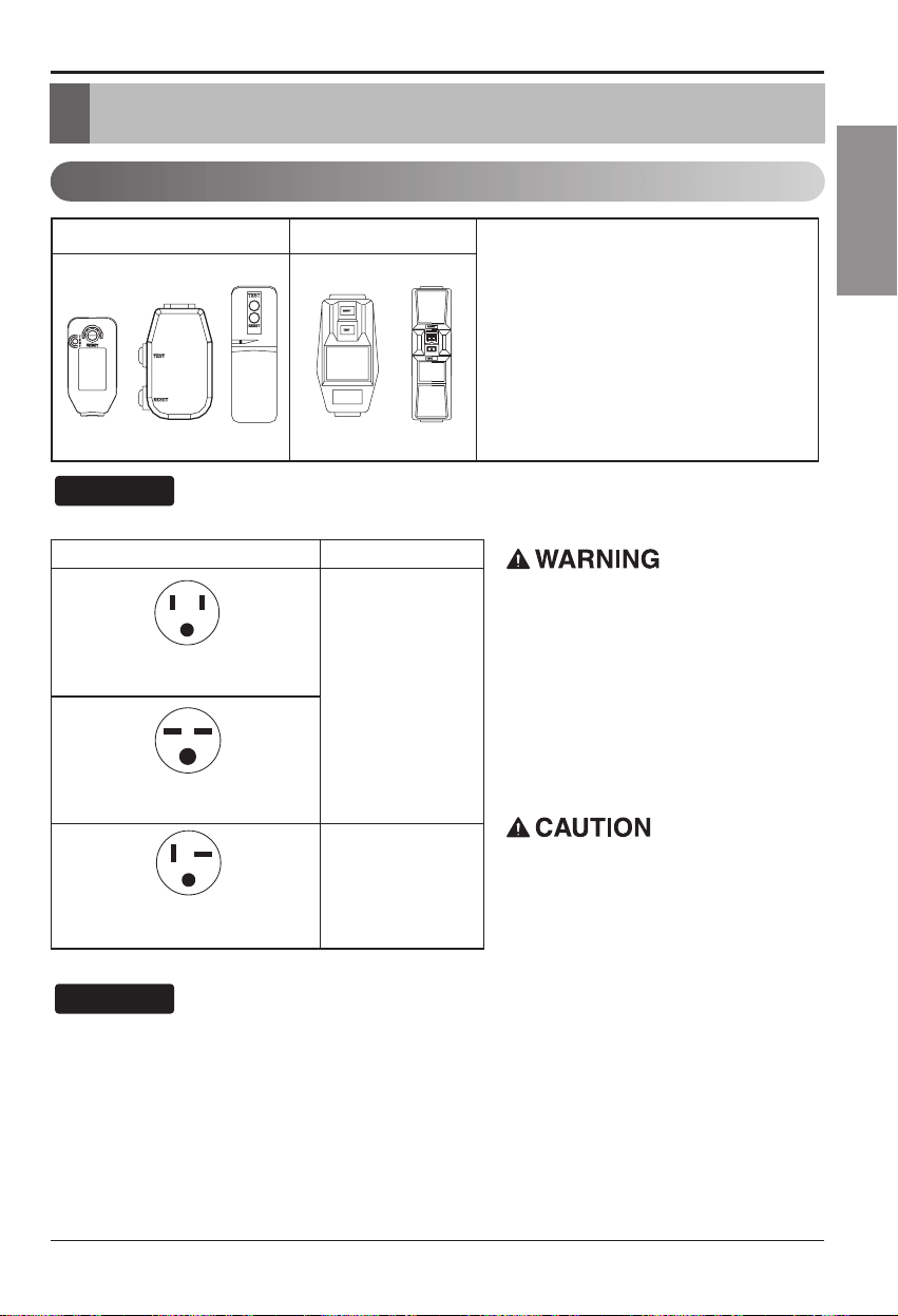
Electrical Data
115V~ 230V~
Power cord may include a current
interrupter device. A test and reset button is
provided on the plug case. The device
should be tested on a periodic basis by first
pressing the TEST button and then the
RESET button. If the TEST button does not
trip or if the RESET button will not stay
engaged, discontinue use of the air
conditioner and contact a qualified service
technician.
Use Wall Receptacle Power Supply
Standard 125V, 3-wire grounding
receptacle rated 15A, 125V AC
Standard 250V, 3-wire grounding
receptacle rated 15A, 250V AC
Use 15 AMP. time
delay fuse or 15 AMP.
circuit breaker.
Use 20 AMP. time
delay fuse or 20 AMP.
circuit breaker.
Standard 250V, 3-wire grounding
receptacle rated 20A, 250V AC
Never push the test button during
operation
Otherwise this plug can damaged.
This device contains chemical, including
lead, known to the State of California to
cause cancer, and birth defects or other
reproductive harm.
Wash hands after handling.
Do not remove, modify or immerse this plug.
If this device trips, the cause it to be
corrected before further use.
The conductors inside this cord are
surrounded by shields, which monitor
leakage current.
These shields are not grounded.
Periodically examine the cord for any
damage. Do not use this product in the
event the shields become exposed.
Avoid shock hazard, this unit can not
be user serviced opening the tamper
resistant. Sealed portion of the unit
voids all warranties and performance
claims. This unit not intended for use
as an on-off switch.
The shape may be different according to its model.
NOTICE
DO NOT USE AN EXTENSION CORD on 230,
208, and 230/208 Volt units.
All wiring should be made in accordance with local
electrical codes and regulations.
Aluminum house wiring may pose special
problems. Consult a qualified electrician.
NOTICE
10 Room Air Conditioner
Electrical Safety
Electrical Safety
IMPORTANT
(PLEASE READ CAREFULLY)
FOR THE USER'S PERSONAL SAFETY, THIS
APPLIANCE MUST BE PROPERLY GROUNDED
The power cord of this appliance is equipped with a
three-prong (grounding) plug. Use this with a standard
three-slot (grounding) wall power outlet to minimize the
hazard of electric shock. The customer should have the
wall receptacle and circuit checked by a qualified
electrician to make sure the receptacle is properly
grounded.
DO NOT CUT OR REMOVE THE THIRD (GROUND)
PRONG FROM THE POWER PLUG.
A. SITUATIONS WHEN THE APPLIANCE WILL BE
DISCONNECTED OCCASIONALLY:
Because of potential safety hazards, we strongly
discourage the use of an adapter plug. However, if you
wish to use an adapter, a TEMPORARY CONNECTION
may be made. Use UL-listed adapter, available from
most local hardware stores.
The large slot in the adapter must be aligned with the
large slot in the receptacle to assure a proper polarity
connection.
:
Attaching the adapter ground terminal to the wall
receptacle cover screw does not ground the appliance
unless the cover screw is metal, and not insulated, and
the wall receptacle is grounded through the house
wiring. The customer should have the circuit checked
by a qualified electrician to make sure the receptacle
is properly grounded.
Disconnect the power cord from the adapter, using one
hand on each. Otherwise, the adapter ground terminal
might break. DO NOT USE the appliance with a broken
adapter plug.
B. SITUATIONS WHEN THE APPLIANCE WILL BE
DISCONNECTED OFTEN.
Do not use an adapter plug in these situations.
Unplugging the power cord frequently can lead to an
eventual breakage of the ground terminal. The wall
power outlet should be replaced by a three-slot
(grounding) outlet instead.
USE OF EXTENSION CORDS
Because of potential safety hazards, we strongly
discourage the use of an extension cord. However, if
you wish to use an extension cord, use a CSA
certified/UL-listed 3-wire (grounding) extension cord,
rated at 15A, 125V.
Owner’s Manual 11
ENGLISH
Installation
Installation
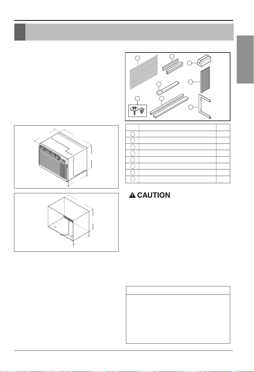
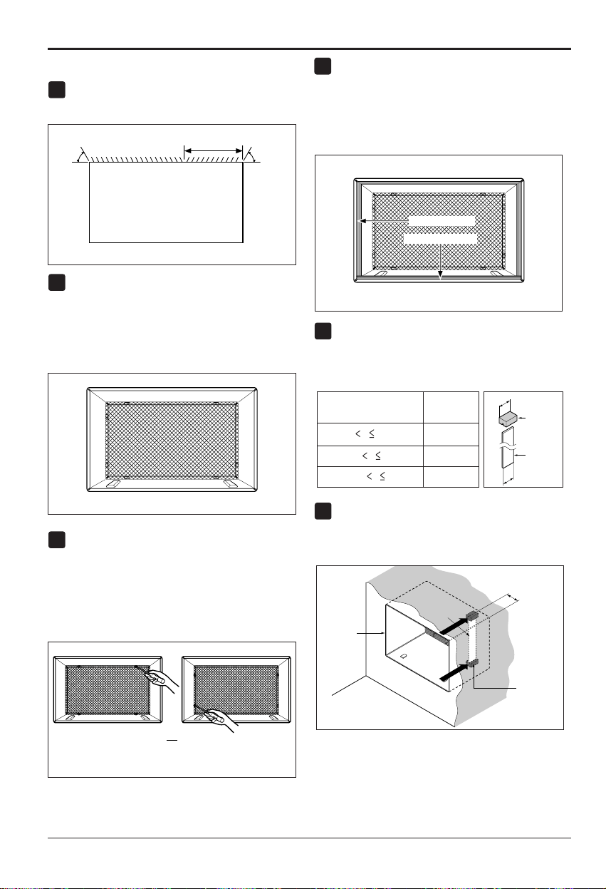
Remove packing sheet from the back of the sleeve, and
packing corner and blue tape from the air conditioner.
INSTALLATION REQUIREMENTS
If you use an existing wall sleeve, you should
measure its dimensions.
Install the new air conditioner according to these
installation instructions to achieve the best
performance. All wall sleeves used to mount the
new air conditioner must be in good structural
condition and have a rear grille to securely attach
the new air conditioner. (FIG. 1)
With the LGE sleeve(optionally supplied with your
unit), you can maintain the best performance of the
new air conditioner. (FIG. 2)
ELECTRICAL SERVICE
Check your available electrical service. The power
supply available must be the same as that shown
on the unit nameplate (found on left side of
cabinet).
All models are equipped with a 3-prong service
plug to provide proper service and safe positive
grounding. Do not change plug in any way. Do not
use an adapter plug. If your present wall outlet does
not match your plug, call a qualified electrician to
make the necessary corrections. SAVE CARTON
for storage and this OWNER'S MANUAL for future
reference. The carton is the best way to store unit
during winter or when not in use.
INSTALLATION HARDWARE
14-
13
/
32
"
(366 mm)
24-
21
/
32
"
(626 mm)
18"(458 mm)
19-
21
/
32
"
(499 mm)
M
O
D
E
T
I
M
E
R
P
O
W
E
R
F
A
N
S
P
E
E
D
F
a
n
H
e
a
t
En
e
r
gy
Sa
v
er
C
o
o
l
T
i
m
e
r
TEMP
'
F
F
1
L
O
W
F
2
H
I
G
H
1
4
5
6
7
3
2
8
2 Size options
2 Size options
To avoid risk of personal injury, property damage, or product
damage due to the weight of this device and sharp edges
that may be exposed:
• Air conditioners covered in this manual pose an excessive
weight hazard. Two or more people are needed to move
and install the unit.
To prevent injury or strain, use proper lifting and carrying
techniques when moving unit.
• Carefully inspect location where air conditioner will be
installed. Be sure it will support the weight of the unit over
an extended period of time.
• Handle air conditioner with care. Wear protective gloves
whenever lifting or carrying the unit. AVOID the sharp
metal fins of front and rear coils.
• Make sure air conditioner does not fall during installation.
REQUIRED TOOLS:
• Tight Fitting gloves
• Standard screwdriver
• Phillips screwdriver
• Pliers
• Sharp knife
• 3/8-inch open end
wrench or adjustable
wrench
• 1/4-inch hex socket
and ratchet
• Tape measure
• Electric drill
• 1/4-inch drill bit
FIG. 1
Air Conditioner
ITEM NAME OF PARTS Q'TY
1 PLASTIC GRILLE 1
2 HORIZONTAL INSULATION STRIPS 2
3 AROUND INSULATION STRIPS 2
4 SUPPORT BLOCK 2
5 BAFFLE 1
6TRIMFRAME 2
7SHIM 2
8
PLASTIC NUTS AND WASHER SCREWS
4
15-
17
/
32
"
(394 mm)
16-
23
/
32
"
(425 mm)
25-
7
/
8
"
(656 mm)
Expanded
aluminum metal grille
FIG. 2
LGE Wall Sleeve
12 Room Air Conditioner
Installation
INSTALLATION
• Pick a location which will allow the conditioned air
to blow into the area you want. Good installation
with special attention to the proper position of the
unit will lessen the chance that service will be
needed.
ITEMS IN INSTALLATION HARDWARE
Youmaynotneedallpartsinthekit.Discard
unused parts
HOW TO INSTALL
Identify the existing wall sleeve before
installing the unit from the listed below.
All wall sleeves used to mount the new Air
Conditioner must be in sound structural condition
and have a rear grille that securely attaches to
sleeve, or rear flange that serves as a stop for the
Air Conditioner,
Remove old air conditioner from existing wall
sleeve.
Clean the interior of an existing sleeve.
(Do not disturb seals.)
Wall sleeve must be securely fastened in wall
before installing the air conditioner. Use the
nails or screws through sleeve into wall, if
needed. Repaint sleeve if needed.
Prepare the wall sleeve for installation of the
unit. If you plan to use your existing wall
sleeve, and it is not LGE, use procedure B or
Cbelow.
Install new unit into wall sleeve.
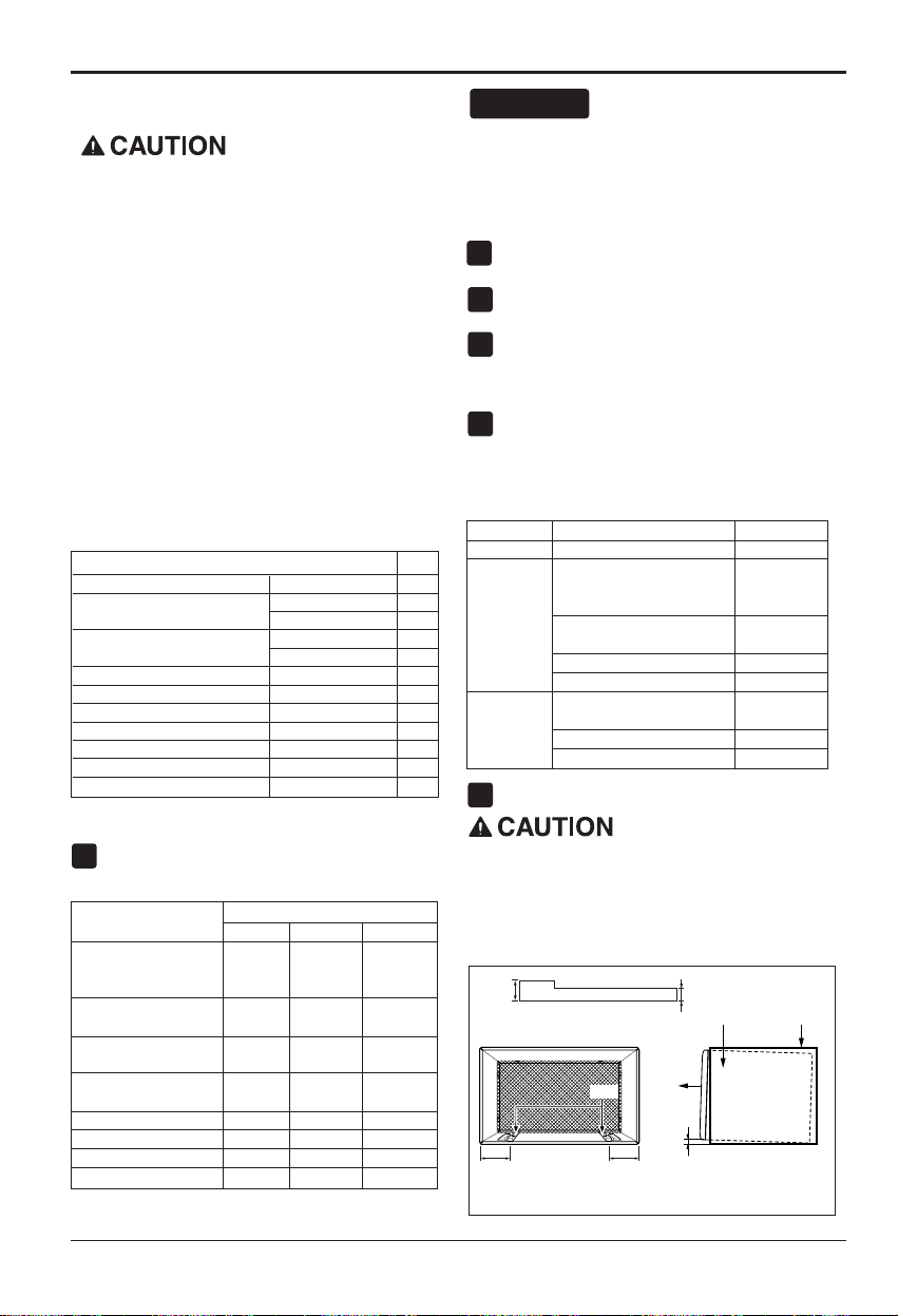
When installation is completed, replacement unit
MUST have a rearward slope as shown. To achieve
1/4" slope, remove the backing from the 11-13/16"
shim strips and attach them as shown below in Fig.
3. Place the higher portion of shim to the front of
the rib on base of wall sleeve.
NOTICE
1
2
3
4
5
6
1/4"
Wall Sleeve
FRONT
UNIT
SHIM PLACEMENT UNIT INSTALLATION
1" high
3
/
4
" High
Shim
6" 6"
FIG. 3
We strongly recommend the removal of the
old wall sleeve and the installation of a new
LGE Wall Sleeve.
Ifyoudecidetokeeptheexistingwallsleeve,
you have to redirect the louvers at the back of
the wall sleeve illustration. The use of pliers is
recommended. If you DO NOT redirect, you run
the risk of poor performance or product failure.
This is not covered under the terms of the LGE
warranty.
ITEM (inches) Qty.
Plastic grille 26
3
/
4
x16
1
/
2
1
Horizontal Insulation Strips
1
3
/
8
x
5
/
8
x27
3
/
16
1
1
3
/
8
x1
3
/
8
x27
3
/
16
1
Around Insulation Strips
1
3
/
8
x
3
/
4
x61
1
/
2
1
1
3
/
8
x1
3
/
8
x61
1
/
2
1
Support Block 1
3
/
4
x1
3
/
8
x4
5
/
16
2
Baffle
14 x
4
1
/
2
x
1
/
8
1
Shim 13 x 1 x
3
/
4
2
Tr im Fr am e 2
Washer Screw 4
Nuts(Plastic) 4
Grille Rear 1
Wall Sleeve Dimensions (inches)
Brand
Width Height Depth
White-Westinghouse
25-1/2 15-1/4
16, 17-1/2
Frigidaire
or 22
Carrier (52F series)
General Electric
26 15-5/8 16-7/8
/Hotpoint
Whirlpool 25-7/8 16-1/2
17-1/8
or 23
Fedders/Emerson 27 16-3/4
16-3/4
or 19-3/4
LGE 25-7/8 15-17/32 16-23/32
Emerson/Fedders 26-3/4 15-3/4 15
Carrier (51S Series) 25-3/4 16-7/8 18-5/8
Friedrich 27 16-3/4 16-3/4
Procedure Brand
Depth(inches)
A LGE 16-23/32
White-Westinghouse
Frigidaire Carrier
16, 17-1/2
(52F series)
or 22
B
General Electric
16-7/8
/Hotpoint
Whirlpool 17-1/8 or 23
Carrier (51S series)
18-5/8
Fedders/Emerson
16-3/4
or 19-3/4
C
Emerson/Fedders 15
Friedrich 16-3/4
Owner’s Manual 13
ENGLISH
Installation
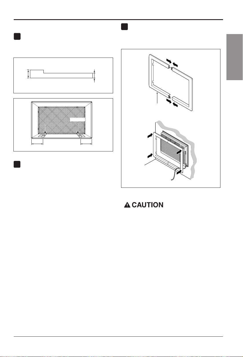
PROCEDURE A
Ifyouareusingthenewsleeve(optionally
supplied with your unit),skip to step 3.
Otherwise, install the plastic grille from the kit.
Cut the plastic grille to 25-1/2" wide and 15-
1/4" high. Place the plastic grille to the inside
of the wall sleeve at the rear flange.
Fasten the 4 washer screws to secure the
grille to the wall sleeve. If you need plastic nuts
to mount plastic grille to the inside of the wall
sleeve, there are plastic nuts in the installation
kit. The nuts are installed from the inside of the
sleeve and are pressed into the square holes
of the rear flanges.
Remove the backing from the Horizontal
Insulation strip 1
3
/
8
x
3
/
8
x27
3
/
16
and attach that
to the inside bottom of the sleeve as shown
below. Remove the backing from the Around
Insulation strip 1
3
/
8
x
3
/
4
x61
1
/
2
and attach that
to the inside front of the sleeve as shown
below.
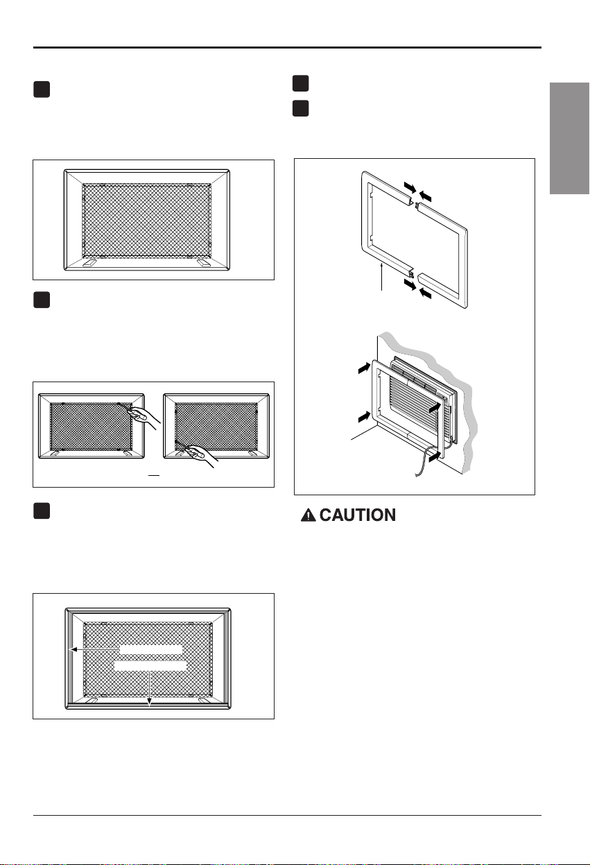
Install the new unit into the wall sleeve.
To assemble trim, snap the tab of each piece
into the slot of the other piece as shown below.
Slide trim over the front of the air conditioner
until trim is flush with sleeve as shown below.
FIG. 4
Around Insulation
Horizontal Insulation
FIG. 6
or
FIG. 5
1
2
3
4
5
Wall
Trim (2 ea)
M
O
D
E
T
I
M
E
R
P
O
W
E
R
F
A
N
S
P
E
ED
F
a
n
H
e
a
t
E
n
e
r
g
y
S
a
v
e
r
C
o
o
l
T
i
m
e
r
T
E
M
P
'
F
F1
L
O
W
F2
H
IG
H
FIG. 7
• Air conditioners covered in this manual pose
an excessive weight hazard. Two or more
people are needed to move and install the
unit.
To prevent injury or strain, use proper lifting
and carrying techniques when moving unit.
• When handling the air conditioner, be careful
to avoid cuts from sharp metal fins on front
and rear coils.
• Make sure air conditioner does not fall during
removal.
14 Room Air Conditioner
Installation
PROCEDURE B
Redirect the louvers at the back of the wall
sleeve to 60° angle as shown in the FIG 8. The
use of pliers is recommended.
If the wall sleeve already has a rear grille, skip
to step 4. If the wall sleeve does not have a
rear grille or louvered panel, install the plastic
grille from the kit. Cut the plastic grille to 25-
1/2" wide and 15-1/4" high. Place the plastic
grille to the inside of the wall sleeve at the rear
flange.
Fasten the 4 washer screws to secure the
grille to the wall sleeve. If you need plastic nuts
to mount plastic grille to the inside of the wall
sleeve, there are plastic nuts in the installation
kit. The nuts are installed from the inside of the
sleeve and are pressed into the square holes
of the rear flanges.
Remove the backing from the Horizontal
Insulation strip 1
3
/
8
x
5
/
8
x27
3
/
16
and attach that
to the inside bottom of the sleeve as shown
below. Remove the backing from the Around
Insulation strip 1
3
/
8
x
3
/
4
x61
1
/
2
and attach that
totheinsidefrontofthesleeveasshown
below.
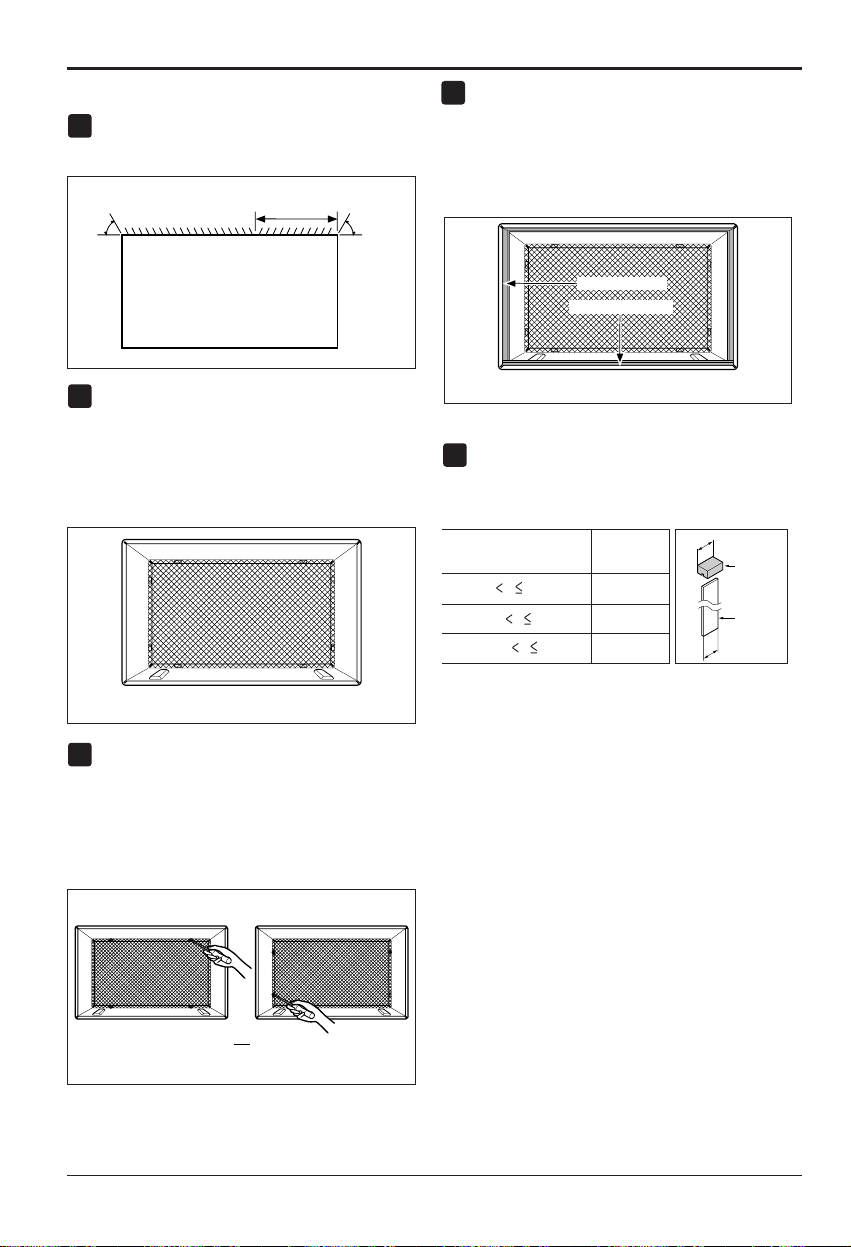
Ifthedepthofyourexistingwallsleeveisless
than or equal to 18", skip to step 7. Otherwise,
cut the baffles and the support blocks
according to length "A" in the table below.
1
4
2
3
FIG. 9
Around Insulation
Horizontal Insulation
FIG. 11
or
FIG.10
Rear Louvers
(Top View)
60°
60°
7
5
/
16
"
FIG. 8
Depth"D" of the existing
wall sleeve (inches)
Length "A"
(inches)
Support
Block
Baffle
A
A
3
/4
1-
3
/4
4
18 D 18-
5
/
8
18-
5
/
8
D 19-
3
/
4
19-
3
/
4
D 22
5
Place the plastic grille
Fasten the screws
FIG. 12
Owner’s Manual 15
ENGLISH
Installation
Wall
Wall
Sleeve
Baffle
(7
5
/
16
")
Front
Support
Block
FIG. 13
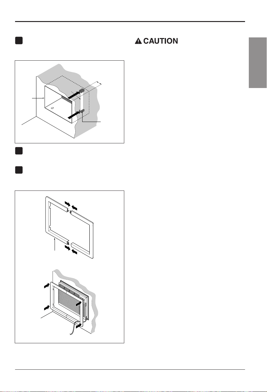
PROCEDURE B
Remove the backing from the support blocks
and attach them to the inside of the wall sleeve
as shown FIG 13. Slide the baffle into slots of
the support blocks.
Install the new unit into the wall sleeve.
To assemble trim, snap the tab of each piece
into the slot of the other piece as shown below.
Slide trim over the front of the air conditioner
until trim is flush with sleeve as shown below.
6
8
7
Wall
Trim (2 ea)
M
O
D
E
T
I
M
E
R
P
O
W
E
R
FA
N
S
PE
ED
F
a
n
H
e
a
t
E
n
e
r
g
y
S
a
v
e
r
C
o
o
l
T
i
m
e
r
T
E
M
P
'
F
F
1
L
O
W
F
2
HI
G
H
FIG. 14
• Air conditioners covered in this manual pose
an excessive weight hazard. Two or more
people are needed to move and install the
unit.
To prevent injury or strain, use proper lifting
and carrying techniques when moving unit.
• When handling the air conditioner, be careful
to avoid cuts from sharp metal fins on front
and rear coils.
• Make sure air conditioner does not fall during
removal.
16 Room Air Conditioner
Installation
PROCEDURE C
Redirect the louvers at the back of the wall
sleeve to 60° angle as shown in the FIG 15.
The use of pliers is recommended.
If the wall sleeve already has a rear grille, skip
to step 4. If the wall sleeve does not have a
rear grille or louvered panel, install the plastic
grille from the kit. Cut the plastic grille to 26-
1/2" wide and 15-1/2" high. Place the plastic
grille to the inside of the wall sleeve at the rear
flange.
Fasten the 4 washer screws to secure the
grille to the wall sleeve. If you need plastic nuts
to mount plastic grille to the inside of the wall
sleeve, there are plastic nuts in the installation
kit. The nuts are installed from the inside of the
sleeve and are pressed into the square holes
of the rear flanges.
Remove the backing from the Horizontal
Insulation strip 1
3
/
8
x1
3
/
8
x27
3
/
16
and attach
that to the inside bottom of the sleeve as
shown below. Remove the backing from the
Around Insulation strip 1
3
/
8
x1
3
/
8
x61
1
/
2
and
attach that to the inside front of the sleeve as
shown below.
If the depth of your existing sleeve is less than
or equal to 18”, skip to step 7. Otherwise, cut
the baffles and the support blocks according to
Length "A" in the table below.
Remove the backing from the support blocks
and attach them to the inside of the wall sleeve
as shown FIG 20. Slide the baffle into slots of
the support blocks
Depth"D" of the existing
wall sleeve (inches)
Length "A"
(inches)
Support
Block
Baffle
A
A
3
/4
1-
3
/4
4
18 D 18-
5
/
8
18-
5
/
8
D 19-
3
/
4
19-
3
/
4
D 22
Wall
Wall
Sleeve
Baffle
Front
Support
Block
(
7
13
/
16
"
)
FIG. 20
FIG. 19
1
4
2
3
FIG. 16
Around Insulation
Horizontal Insulation
FIG. 18
or
FIG. 17
Rear Louvers
(Top View)
60°
7
13
/
16
"
60°
FIG. 15
5
6
Place the plastic grille
Fasten the screws
Installation
Owner’s Manual 17
ENGLISH
PROCEDURE C
Remove the backing from the 13" shim strips
and attach them as shown below in Fig. 21.
The higher portion of shim is to be placed in
front of the rib on the base of wall sleeve.
Install the new unit into the wall sleeve
To assemble trim, snap the tab of each piece
into the slot of the other piece as shown below.
Slide trim over the front of the air conditioner
until trim is flush with sleeve as shown below.
8
• Air conditioners covered in this manual pose
an excessive weight hazard. Two or more
people are needed to move and install the
unit.
To prevent injury or strain, use proper lifting
and carrying techniques when moving unit.
• When handling the air conditioner, be careful
to avoid cuts from sharp metal fins on front
and rear coils.
• Make sure air conditioner does not fall during
removal.
Wall
Trim (2 ea)
M
O
D
E
T
I
M
E
R
P
O
W
E
R
F
A
N
S
P
E
E
D
F
a
n
H
ea
t
E
n
e
r
g
y
S
a
v
e
r
C
o
o
l
T
im
er
T
E
M
P
'
F
F
1
L
O
W
F
2
H
I
G
H
FIG.23
9
7
FIG. 21
1" high
3
/
4
" High
Shim (2EA)
6" 6"
FIG. 22
18 Room Air Conditioner
Operating Instructions
Operating Instructions
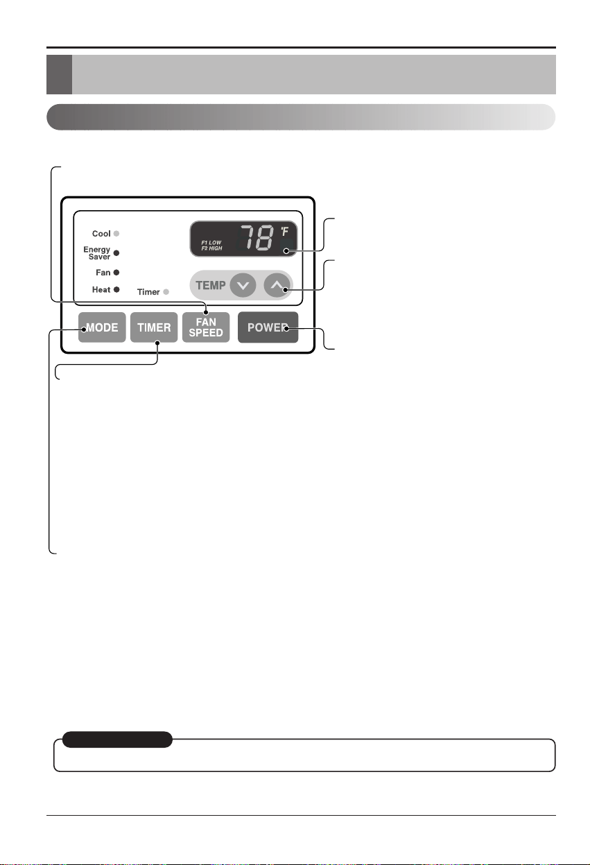
Controls
The controls will look like one of the following.
REMOTE CONTROL SIGNAL
RECEIVER
POWER
MODE
-
Push this button to shift mode of operation from COOL → ENERGY SAVER → FAN → HEAT
- COOL:
• Fan runs continually for normal cooling operation.
- ENERGY SAVER:
• The fan stops when the compressor stops cooling. Approximately every 3 minutes the fan will turn on and the unit will
check the room air temperature to determine if cooling is needed.
- FAN:
• Fan-only operation.
- HEAT:
• Fan runs continually for normal heating operation.
TIMER
- SHUT-OFF TIME
• You will usually use shut-off time while you sleep.
• If unit is running, use Timer to set number of hours until shut-off.
• For your sleeping comfort, once Time is set, the Temperature
setting will raise 2°F after 30 min., and once again after another
30 min.
• Push Timer button to advance setting from 1Hour → 2Hours → ...
→ 12Hours maximum.
- START TIME
• If unit is off, use Timer to set number of hours before unit starts.
• Push Timer button to advance setting from 1Hour → 2Hours → ...
→ 12Hours maximum.
TEMPERATURE SETTING
• Use this button to automatically control the
temperature of the room.
The temperature can be set within a range of
60°F to 86°F by increments of 1°F.
• The setting appears in the display.
• To turn the air conditioner ON, push this button.
To turn the air conditioner OFF, push the button
again.
• This button takes priority over any other button.
FAN SPEED
• Every time you push this button, it advances the setting as follows:
{High[ F2 ] → Low[ F1 ] → High[ F2 ]}
AUTO RESTART
When power is restored after an electrical power failure, the unit will begin to run at its last setting.
Owner’s Manual 19
ENGLISH
Operating Instructions
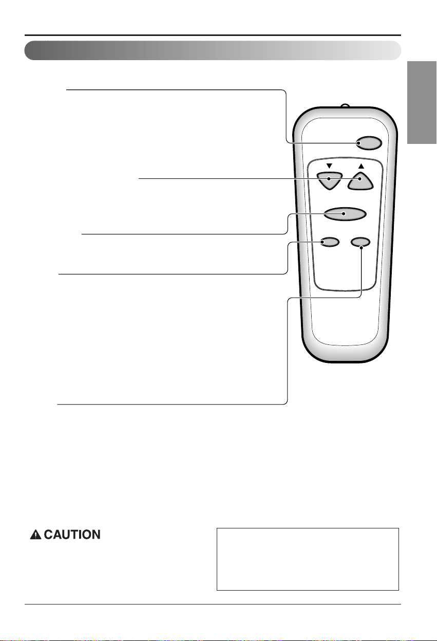
Remote control
The remote control and control panel will look like one of the following pictures.
Power
Temp
Fan Speed
Timer Mode
POWER
• To turn the air conditioner ON, push this button.
To turn the air conditioner OFF, push the button again.
• This button takes priority over any other button.
TEMPERATURE SETTING
• Use this button to automatically control the temperature of the room.
The temperature can be set within a range of 60°F to 86°F by
increments of 1°F.
• The setting appears in the display.
FAN SPEED
• Every time you push this button it advances the setting as follows:
{High[ F2 ] → Low[ F1 ] → High[ F2 ]}
TIMER
- SHUT-OFF TIME
• You will usually use shut-off time while you sleep.
• If unit is running, use Timer to set number of hours until shut-off.
• For your sleeping comfort, once Time is set, the Temperature setting will
raise 2°F after 30 min, and once again after another 30 min.
• Push Timer button to advance setting from 1Hour
→ 2Hours → ... →
12Hours maximum.
- START TIME
• If unit is off, use Timer to set of hours before unit starts.
• Push Timer button to advance setting from 1Hour
→ 2Hours → ... →
12Hours maximum.
MODE
- Push this button to shift mode of operation from COOL
→
ENERGY SAVER
→
FAN
→
Heat.
- COOL:
• Fan runs continually for normal cooling operation.
- ENERGY SAVER:
• The fan stops when the compressor stops cooling. Approximately every 3 minutes the fan will turn on
and the unit will check the room air temperature to determine if cooling is needed.
- FAN:
• Fan-only operation.
- HEAT:
• Fan runs continually for normal heating operation.
When the air conditioner has been performed its
cooling or heating operation and is turned off or
set to the fan position, wait at least 3 minutes
before resetting to the cooling operation again.
A slight heat odor may come from the unit
when first switching to HEAT after the
cooling season is over. This odor, caused
by fine dust particles on the heater, will
disappear quickly. This is harmless.
20 Room Air Conditioner
Operating Instructions
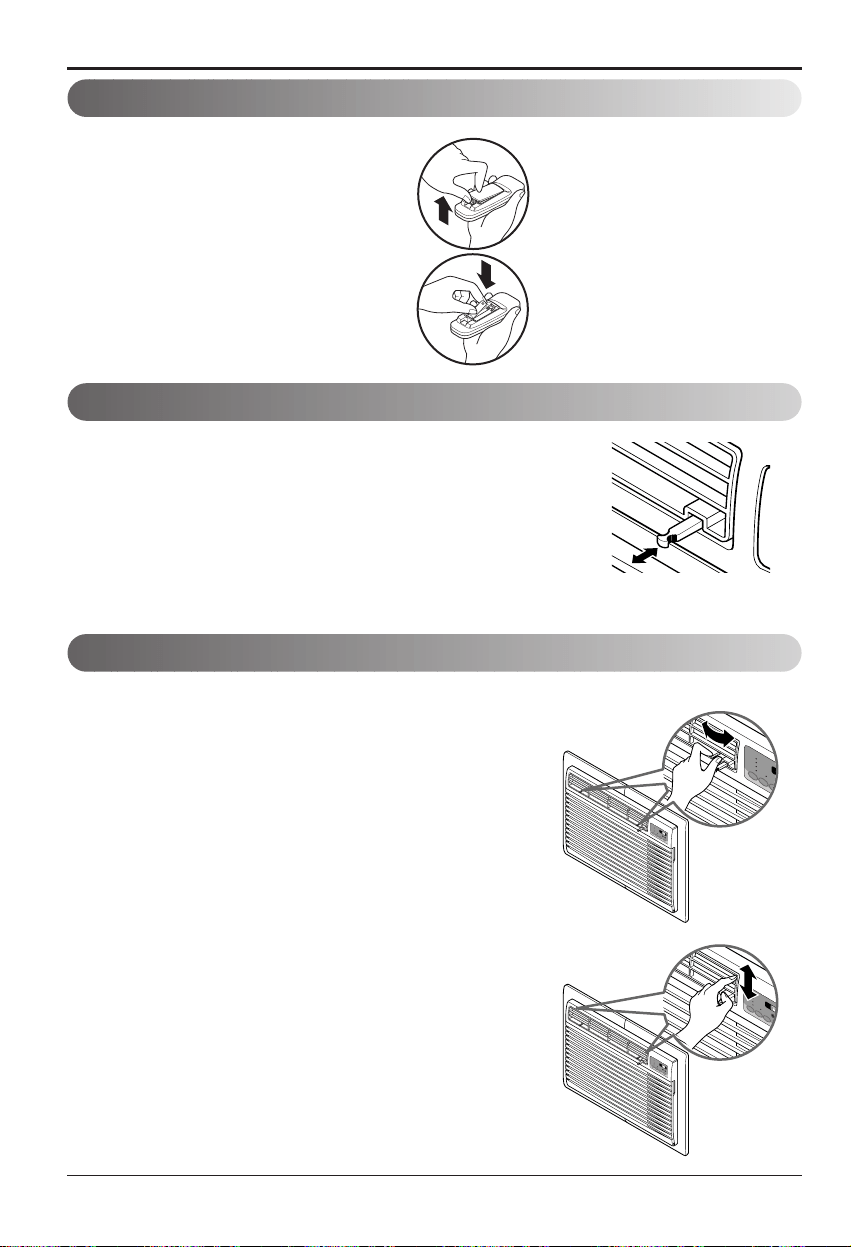
How to insert Batteries
1. Remove the cover from the back of the remote
controller.
2. Insert two batteries.
• Be sure that the (+) and (-) directions are
correct.
• Be sure that both batteries are new.
3. Re-attach the cover.
• Do not use rechargeable batteries.
Such batteries differ from standard
dry cells in shape, dimensions, and
performance.
• Remove the batteries from the
remote controller if the air
conditioner is not going to be used
for an extended length of time.
Ventilation Control
Air Direction
Push the lever to the "CLOSE" position to cool, heat or
recirculate room air only.
Pullthelevertothe"OPEN"positiontoexhaustsmokeor
stale air from the room.
This feature is best used in conjunction with the FAN ONLY
position.
The direction of air can be controlled by adjusting the horizontal
and vertical louvers.
• HORIZONTAL AIR-DIRECTION CONTROL
The horizontal air direction is adjusted by moving the vertical
louver.
The lever for the vertical louver is located in the right and left side
of the air discharge.
• VERTICAL AIR-DIRECTION CONTROL
The vertical air direction is adjusted by moving the horizontal
louver.
M
O
D
E
T
IM
E
R
P
O
F
A
N
S
PE
E
D
F
a
n
H
e
a
t
Energy
Saver
C
o
o
l
T
im
e
r
T
E
M
P
F
1
L
O
W
F
2
H
I
G
H
PULL OPEN / PUSH CLOSE
M
O
D
E
TIM
ER
F
A
N
S
P
E
E
F
an
Heat
E
n
e
r
g
y
S
a
v
e
r
Co
ol
Tim
er
T
E
M
F
1 L
O
F
2 H
I
M
O
D
E
TI
M
E
R
P
O
W
E
R
F
A
N
S
P
E
E
D
F
a
n
H
e
a
t
E
n
e
r
g
y
S
a
v
e
r
C
o
o
l
T
i
m
e
r
T
E
M
P
'
F
F
1
L
O
W
F
2
H
I
G
H
M
OD
E
TIM
E
R
P
O
W
E
R
F
A
N
S
P
E
E
D
F
a
n
H
e
a
t
E
n
er
g
y
S
av
e
r
C
o
o
l
T
i
m
e
r
T
E
M
P
'
F
F
1
L
O
W
F
2
H
IG
H
Owner’s Manual 21
ENGLISH
M
O
D
E
T
I
M
E
R
P
O
W
E
R
F
A
N
S
P
E
E
D
F
a
n
H
e
a
t
E
n
e
r
g
y
S
a
v
e
r
C
o
o
l
T
i
m
e
r
T
E
M
P
'
F
F
1
L
O
W
F
2
H
I
G
H
M
O
D
E
T
I
M
E
R
P
O
W
E
R
F
A
N
S
P
E
E
D
F
a
n
H
e
a
t
E
n
e
r
g
y
S
a
v
e
r
C
o
o
l
T
im
e
r
T
E
M
P
'
F
F
1
L
O
W
F
2
H
I
G
H
M
O
D
E
T
I
M
E
R
P
O
W
E
R
F
A
N
S
P
E
E
D
F
a
n
H
e
a
t
E
n
e
r
g
y
S
a
v
e
r
C
o
o
l
T
i
m
e
r
T
E
M
P
'
F
F
1
L
O
W
F
2
H
I
G
H
M
O
D
E
T
I
M
E
R
P
O
W
E
R
F
A
N
S
P
E
E
D
F
a
n
H
e
a
t
E
n
e
r
g
y
S
a
v
e
r
C
o
o
l
T
i
m
e
r
T
E
M
P
'
F
F
1
L
O
W
F
2
H
IG
H
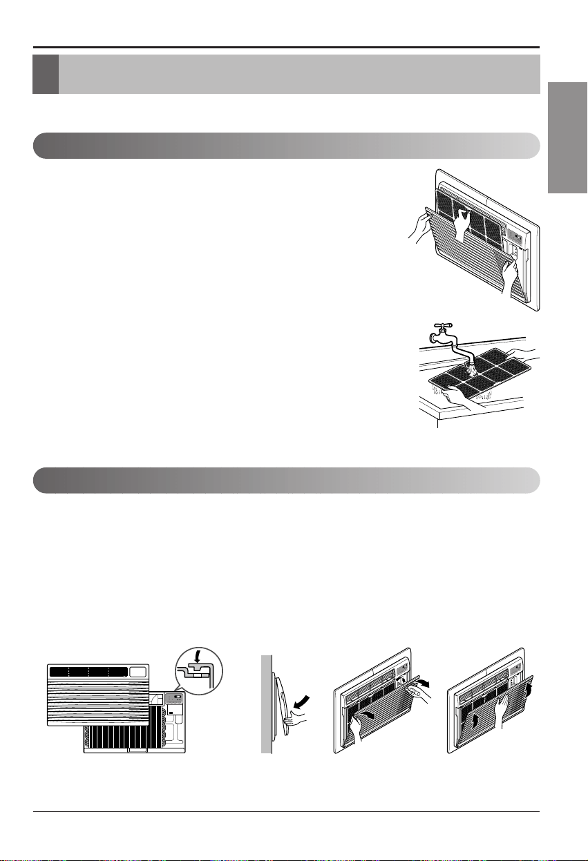
Air Filter Cleaning
How to Attach Front Grille to Cabinet
Maintenance and Service
Maintenance and Service
TURN THE AIR CONDITIONER OFF AND REMOVE THE PLUG FROM THE POWER OUTLET.
Theairfiltershouldbecheckedatleasttwiceamonthtoseeifcleaningis
necessary. Trapped particles in the filter will build up and block the airflow.
This reduces the cooling capacity and also causes an accumulation of
frost on the cooling coils.
If the filter becomes worn or damaged you should replace immediately.
Replacement filters are available from your salesperson, dealer, and the
authorized customer service centers.
1. Open the inlet grille downward by pulling out the top of the inlet grille.
2. Remove the air filter from the front grille assembly by pulling the air
filter up slightly.
3. Wash the filter using lukewarm water below 40°C(104°F).
4. Gently shake the excess water from the filter completely. Replace the
filter.
1. Pull down front grille from the cabinet top.
2. Push front grille’s tips toward the cabinet in
order to insert front grille’s tabs into the
cabinet.
3. Open the inlet grille.
4. Tighten the screw through the front grille into
the plate of control box.
5. Close inlet grille.
The front grille can be removed for cleaning or to check the model and serial numbers.
For your safety, you should attach the front grille as the following procedures.
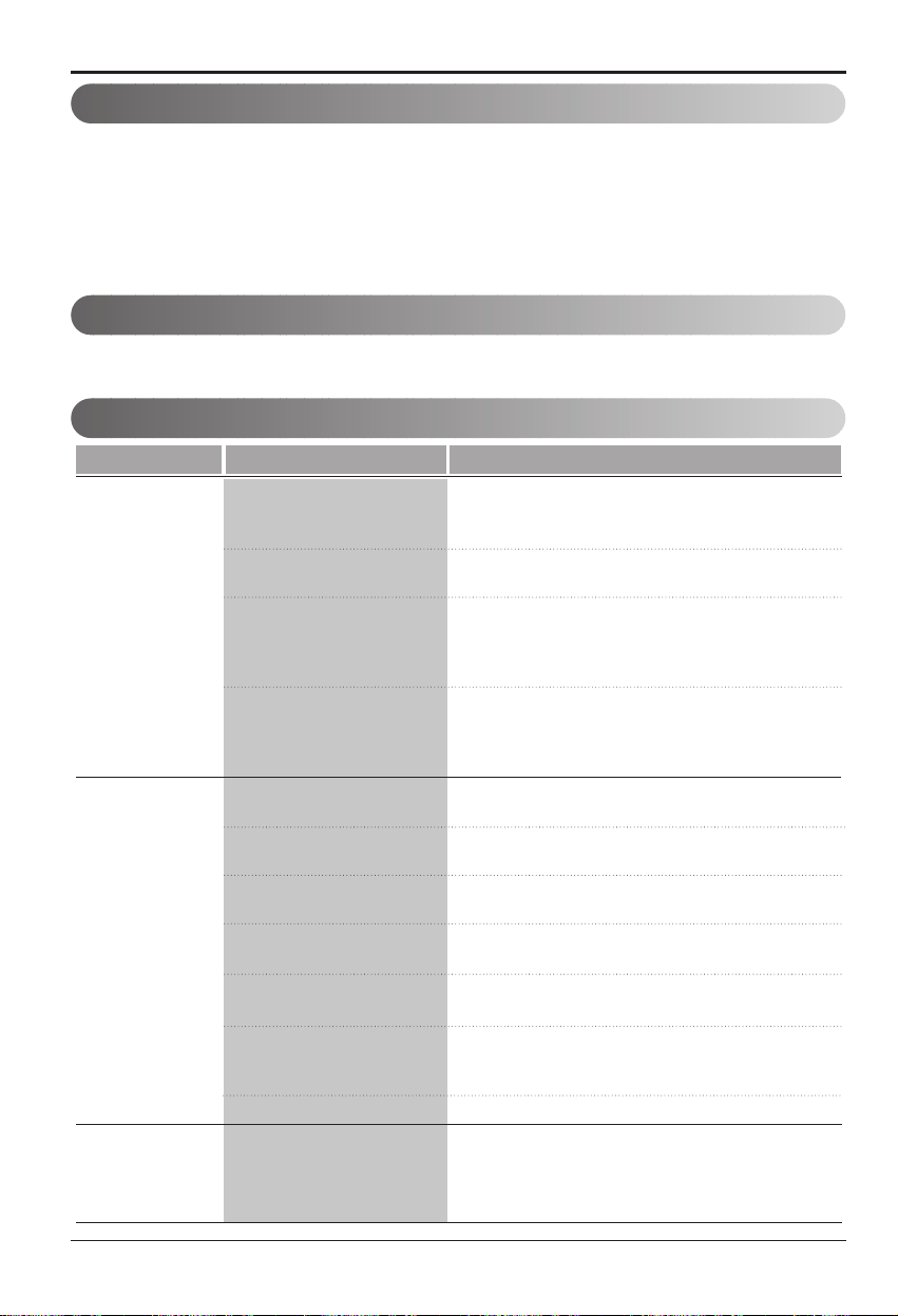
22 Room Air Conditioner
Maintenance and Service
Problem Possible Causes What To Do
■ The air conditioner is
unplugged or not plugged
in completely
■ The fuse is blown/circuit
breaker is triggered
■ Power failure.
■ The current interrupter
device is tripped.
■ Air flow is restricted
■ TEMP Control set too
higher number.
■ The air filter is dirty.
■ The air conditioner was
just turned on.
■ The room may have been
hot.
■ Cold air is escaping.
■ Cooling coils are iced up
■ Thecoolingcoilsareiced
over.
• Make sure the plug is completely plugged into the
outlet
• Check the fuse/circuit breaker box and replace the
fuse or reset the breaker
• In the event of a power failure, set the power control
to OFF. When the power is restored, wait 3 minutes
to restart the air conditioner to prevent the
compressor from overloading
• Press the RESET button located on the power cord
plug. If the RESET button will not stay engaged,
discontinue use of the air conditioner and contact a
qualified service technician.
• Make sure there are no curtains, blinds, furniture or
other obstacles in front of the air conditioner
• Set the TEMP control to a lower number.
• Clean the filter at least every 2 weeks. Refer to the
“Maintenance and Service” section of the manual.
• After the air conditioner is turned on, you need to
give the air conditioner some time to cool the room.
• When the air conditioner is first turned on
you need to allow time for the room to cool down.
• Check for open furnace floor resisters and cold air
returns.
• CLOSE the air conditioner vent
• See Ice appears on the air conditioner below
• Ice may block the air flow and obstruct the air
conditioner from properly cooling the room.
• Set the mode control at HIGH fan or high cool with
the high temperature.
The air conditioner
does not operate
at all
Air conditioner
does not cool
Ice appears on the
air conditioner.
Abnormal Operation
Normal Operation
• You may hear a pinging noise caused by water being picked up and thrown against the condenser on rainy
days or when the humidity is high. This design feature helps remove moisture and improve efficiency.
• You may hear the thermostat click when the compressor cycles on and off.
• Water will collect in the base pan during high humidity or on rainy days. The water may overflow and drip
from the outdoor side of the unit.
• The fan will run even when the compressor does not.
To save time and expense, check the following before calling for an authorized service center
For Models installed in North America-If service or parts are required first make the check recommended below.
Services

Memo
Owner’s Manual 23
ENGLISH
2 Aire Acondicionado
PARA SUS ARCHIVOS
Escriba aquí el modelo y número de serie:
Modelo n°:
Serie n°:
Puede encontrar estos datos en la etiqueta situada en el lateral de
cada unidad.
Nombre del distribuidor:
Fechadecompra:
■ Adjunte su recibo a esta página con la grapadora para el
momento que lo necesite para probar la fecha de su adquisición
oparalavalidacióndelagarantía.
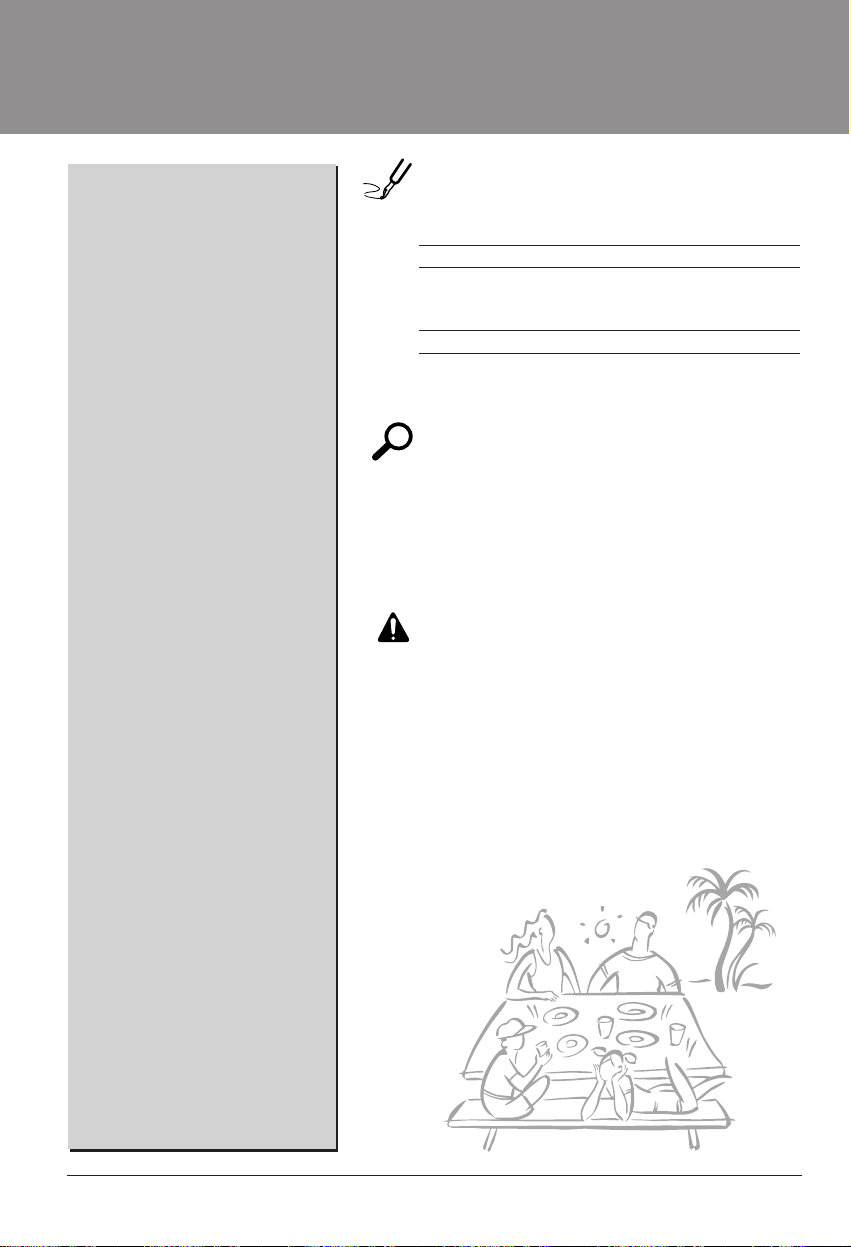
LEAESTEMANUAL
En su interior encontrará muchos consejos útiles sobre la utilización
y mantenimiento de su acondicionador de aire. Unos pocos
cuidados por su parte le pueden ahorrar mucho tiempo y dinero
durante la vida de su acondicionador de aire.
En la tabla de consejos para la solución rápida de problemas
encontrará muchas respuestas a los problemas más habituales. Si
revisa primero nuestra Tabla de Consejos para la solución rápida
de problemas, tal vez no necesite llamar nunca al servicio técnico.
PRECAUCIÓN
• Póngase en contacto con un técnico del servicio
autorizado para realizar la reparación y mantenimiento
de esta unidad.
• Póngase en contacto con un instalador para realizar la
instalación de esta unidad.
• Cuando se va a cambiar el cable eléctrico, el trabajo
de reemplazamiento debe ser realizado únicamente
por personal autorizado, utilizando las piezas de
cambio genuinas únicamente.
• El trabajo de reemplazamiento debe ser realizado de
acuerdo con el Código Eléctrico Nacional únicamente
por personal autorizado.
Precauciones de seguridad ...........3
AntesdelaOperación....................7
Introducción.....................................8
Seguridad eléctrica .........................9
Instalación......................................11
Instrucciones operativas..............18
Cuidado y Mantenimiento ............21
Aire Acondicionado Manual del usuario
TABLA DE CONTENIDOS
ESPAÑOL
Manual del usuario 3
Precauciones de seguridad
Precauciones de seguridad
Paraevitarlesionesalusuariooaotraspersonasydañosalapropiedad,estasinstrucciones
estén seguirse.
■
Una operación incorrecta por ignorar las instrucciones provocará lesiones o daños. La seriedad se clasifica
por las siguientes indicaciones.
■ Significados de los símbolos utilizados en este manual.
ADVERTENCIA
PRECAUCION
Este símbolo indica la posibilidad de muerte o de seria lesión.
Este símbolo indica sólo la posibilidad de lesiones o daños a la propiedad
ADVERTENCIA
■ Instalación
No hacer.
Siga estas instrucciones.
No utilice un cable de
alimentación, enchufe o una
toma suelta que esté dañada.
• De lo contrario, podría
provocar un incendio o
descarga eléctrica.
Enchufesiempreaun
tomacorriente que tenga
toma a tierra.
• De lo contrario, podría
provocar un incendio o
descarga eléctrica.
No modifique ni alargue el
cable de alimentación.
• De lo contrario, puede
provocar una descarga
eléctrica o incendio debido a
la generación de calor.
M
O
D
E
T
I
M
E
R
P
O
W
E
R
F
A
N
S
P
E
E
D
Fan
He
a
t
E
n
e
r
g
y
S
a
v
e
r
Co
ol
Timer
T
E
M
P
'
F
F
1
L
O
W
F
2
H
I
G
H
M
O
D
E
T
I
M
E
R
P
O
W
E
R
FAN
S
PEE
D
F
a
n
H
e
a
t
E
n
e
r
g
y
S
a
v
e
r
C
o
o
l
T
i
m
e
r
T
E
M
P
'
F
F
1
L
O
W
F
2
H
I
G
H
No desmonte ni modifique
los productos.
• Puede ocasionar fallos y una
descarga eléctrica.
Tenga cuidado al
desembalar e instalar el
aparato.
• Los bordes afilados pueden
provocar lesiones.
No use el cable de alimentación
cerca gas inflamable o
materiales combustibles tales
como la gasolina, benceno,
disolvente, etc.
• Podría ocurrir una explosión o
incendio.
M
O
D
E
T
I
M
E
R
P
O
W
E
R
F
A
N
S
P
E
E
D
F
a
n
H
e
a
t
E
ne
rg
y
S
a
ve
r
C
o
o
l
T
i
m
e
r
T
E
M
P
'
F
F
1
LO
W
F
2
H
I
G
H
M
O
D
E
T
I
M
E
R
P
O
W
E
R
F
A
N
S
P
E
E
D
F
a
n
H
e
a
t
E
n
e
r
g
y
S
a
v
e
r
C
o
o
l
T
i
m
e
r
T
E
M
P
'
F
F
1
L
O
W
F
2
H
I
G
H
Gasolin
M
O
D
E
T
I
M
E
R
P
O
W
E
R
F
A
N
S
P
E
E
D
F
a
n
H
e
a
t
E
n
e
r
g
y
S
a
v
e
r
C
o
o
l
T
i
m
e
r
T
EM
P
'
F
F
1
L
O
W
F
2
H
I
G
H
4 Aire Acondicionado
Precauciones de seguridad
■ Operación
No ponga el cable de
alimentación cerca de un
calentador.
• Puede ocasionar un incendio
y una descarga eléctrica.
No permita que entre agua
en las piezas eléctricas.
• Puede provocar fallos en el
producto o descargas
eléctricas.
Utilice un paño suave para
limpiar. No utilice cera,
disolventes o detergentes
fuertes.
•
La apariencia del aparato de aire
acondicionado puede deteriorar,
cambiar el color o desarrollar
flujos en las superficies.
M
O
D
E
T
I
M
E
R
P
O
W
E
R
F
A
N
S
P
E
E
D
Fa
n
H
e
a
t
E
n
e
r
g
y
S
a
v
e
r
Co
ol
Tim
e
r
T
E
M
P
'
F
F
1
L
O
W
F
2
H
I
G
H
M
O
D
E
T
I
M
E
R
P
O
W
E
R
F
A
N
S
P
E
E
D
Fa
n
H
e
at
E
n
e
r
g
y
S
a
v
e
r
Coo
l
T
i
m
er
T
E
M
P
'
F
F
1
L
O
W
F
2
H
I
G
H
Wax
Thinner
M
O
D
E
T
I
M
E
R
P
O
W
E
R
F
A
N
S
P
E
E
D
F
a
n
H
e
a
t
E
n
e
r
g
y
S
a
v
e
r
C
o
o
l
T
i
m
e
r
T
E
M
P
'
F
F
1
L
O
W
F
2
H
IG
H
Ventile bien la sala al usar
este aparato con una estufa,
etc.
• Puede ocurrir un falta de
oxígeno.
Apague el aparato y el
interruptor diferencial
primero antes de limpiar la
unidad.
•
Debido a que el ventilador gira
a alta velocidad durante el
funcionamiento, podría
ocasionar lesiones.
Apague el interruptor de
alimentación principal cuando
no vaya a utilizar el aparato
durante mucho tiempo.
• Evitará el arranque accidental
y la posibilidad de lesiones.
M
O
D
E
T
I
M
E
R
P
O
W
E
R
F
A
N
S
P
E
E
D
F
a
n
H
e
a
t
E
n
e
r
g
y
S
a
v
e
r
C
o
o
l
T
i
m
e
r
T
E
M
P
'
F
F
1
L
O
W
F
2
H
I
G
H
M
O
D
E
T
I
M
E
R
P
O
W
E
R
F
A
N
S
P
E
E
D
F
a
n
H
e
a
t
E
n
e
r
g
y
S
a
v
e
r
C
o
o
l
T
i
m
e
r
T
E
M
P
'
F
F
1
L
O
W
F
2
H
I
G
H
M
O
D
E
T
I
M
E
R
P
O
W
E
R
F
A
N
S
P
E
E
D
F
a
n
H
e
a
t
E
n
e
r
g
y
S
a
v
e
r
C
o
o
l
T
i
m
e
r
T
E
M
P
'
F
F
1
L
O
W
F
2
H
I
G
H
Desenchufe la unidad si oye
un sonido extraño, olores, o
si observa salir humo.
• De lo contrario, puede ocurrir
un incendio y un accidente
por descarga eléctrica.
No abra la parrilla de
entrada al aparato mientras
está en funcionamiento.
• De lo contrario, pueden ocurrir
descargas eléctricas y fallos.
Sientraaguaenelproducto,
apague el interruptor de la
carcasa principal del aparato.
Póngase en contacto con el
centro de servicio despuésde
haber sacado el enchufe del
tomacorriente.
M
O
DE
T
I
M
E
R
P
O
W
E
R
F
A
N
S
P
E
E
D
F
a
n
H
e
a
t
E
n
e
r
g
y
S
a
v
e
r
C
o
o
l
T
i
m
e
r
T
E
M
P
'
F
F
1
L
O
W
F
2
H
I
G
H
M
O
D
E
T
I
M
E
R
P
O
W
E
R
F
A
N
S
P
E
E
D
F
a
n
H
e
a
t
En
ergy
S
a
v
er
C
o
o
l
T
i
m
e
r
T
E
M
P
'
F
F
1
L
O
W
F
2
H
I
G
H
M
O
D
E
T
I
M
E
R
P
O
W
E
R
F
A
N
S
P
E
E
D
F
a
n
H
e
a
t
Ene
r
g
y
S
a
v
er
C
o
o
l
T
i
m
e
r
T
E
M
P
'
F
F
1
L
O
W
F
2
H
I
G
H
M
O
D
E
T
I
M
E
R
P
O
W
E
R
F
A
N
S
P
E
E
D
F
a
n
H
e
at
E
n
er
g
y
S
a
v
er
Co
o
l
T
im
er
T
E
M
P
'
F
F
1
LOW
F2
HI
GH
M
O
D
E
T
I
M
E
R
P
O
W
E
R
FA
N
SP
EE
D
F
a
n
H
e
a
t
E
n
e
r
g
y
S
a
v
e
r
C
o
o
l
T
i
m
e
r
T
E
M
P
'
F
F
1
L
O
W
F
2
H
I
G
H
No use el cable de alimentación
cerca gas inflamable o materiales
combustibles tales como la
gasolina, benceno, disolvente, etc.
• Puede ocasionar una
explosión o descarga
eléctrica.
No comparta el
tomacorriente con otros
electrodomésticos.
•
De lo contrario, puede provocar
una descarga eléctrica o incendio
debido a la generación de calor.
Saque el enchufe en caso de
necesidad, sosteniendo la
cabeza del enchufe y no lo
toque con las manos mojadas.
•
De lo contrario, podría provocar
un incendio o descarga
eléctrica.
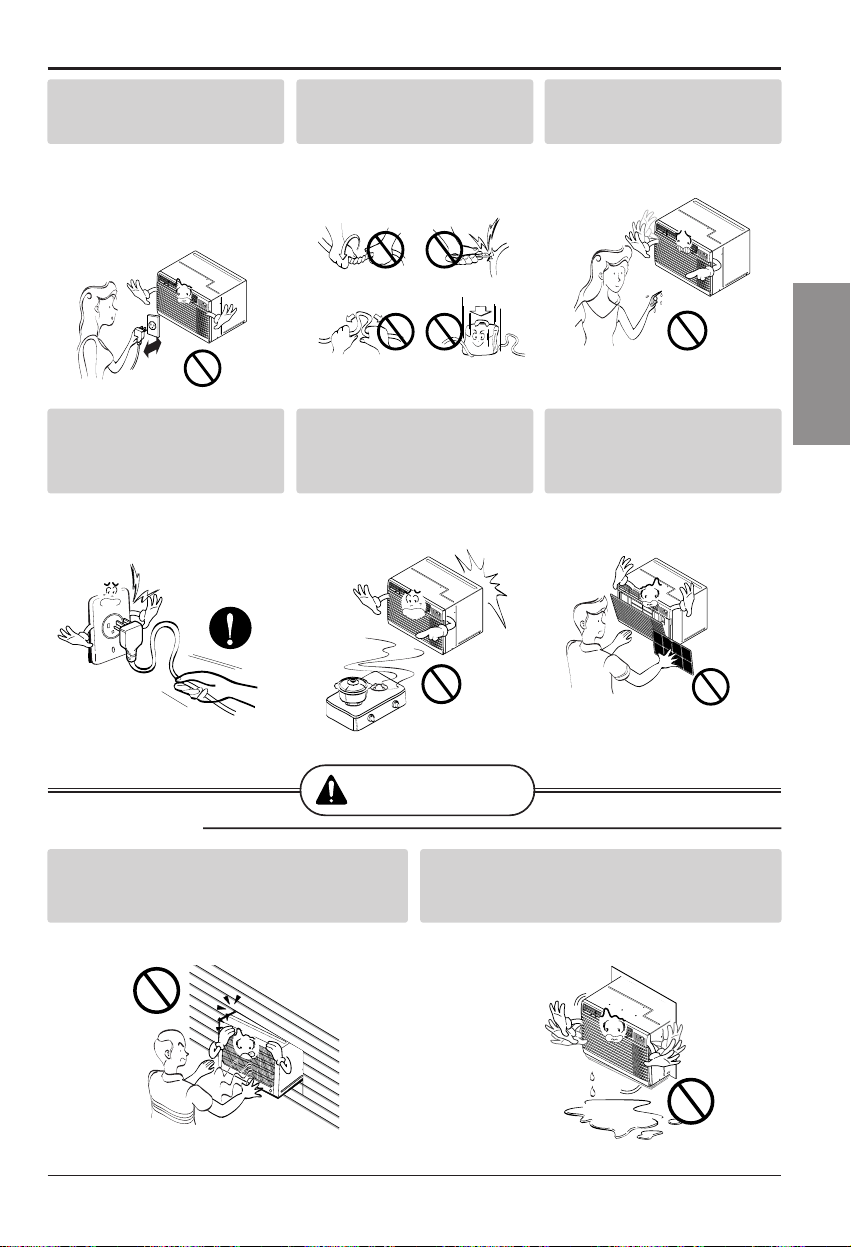
ESPAÑOL
Manual del usuario 5
Precauciones de seguridad
PRECAUCION
■ Instalación
No opere ni detenga la
unidad insertando o
estirando de enchufe.
• De lo contrario, puede
provocar una descarga
eléctrica o incendio debido a
la generación de calor.
No dañeniuseunenchufe
de alimentaciónno
especificado.
• Provocará descargas
eléctricas o incendios.
No toque el producto con
las manos mojadas o en un
ambiente húmedo.
• Provocará descargas
eléctricas.
M
O
D
E
T
I
M
E
R
P
O
W
E
R
F
A
N
S
P
E
E
D
F
a
n
H
e
a
t
E
n
e
r
g
y
S
a
v
e
r
C
o
o
l
T
im
e
r
T
E
M
P
'
F
F
1
L
OW
F
2
HI
GH
M
O
D
E
T
IM
E
R
P
O
W
E
R
F
A
N
S
P
E
E
D
F
a
n
H
e
a
t
E
n
e
r
g
y
S
a
v
e
r
C
o
o
l
T
i
m
e
r
T
E
M
P
'
F
F
1
L
O
W
F
2
H
I
G
H
Sostenga el enchufe por su
cabeza al sacarlo.
• Podría ocasionar una
descarga eléctrica y daños.
Cuando haya un escape de
gas, abra la ventana para
ventilar antes de poner en
marcha la unidad.
• De lo contrario, podría ocurrir
una explosión o incendio.
No toque las partes
metálicas del aparato al
sacar el filtro del aire.
• Son puntiagudas y pueden
provocar lesiones.
M
O
D
E
T
IM
E
R
P
O
W
E
R
F
A
N
S
P
E
E
D
F
a
n
H
e
a
t
E
n
e
r
g
y
S
a
v
e
r
C
o
o
l
T
i
m
e
r
T
E
M
P
'
F
F
1
L
O
W
F
2
H
I
G
H
M
O
D
E
T
IM
E
R
P
O
W
E
R
F
A
N
S
P
E
E
D
F
an
H
ea
t
E
n
e
r
g
y
S
a
v
e
r
C
o
ol
T
i
m
e
r
T
E
M
P
'
F
F1
LO
W
F
2
HI
GH
Instale el producto de modo que el ruido o
el aire caliente producido por la unidad
externa no moleste a los vecinos.
• De lo contrario puede dar lugar a disputas
vecinales.
Mantenga nivelado el producto al instalarlo.
• De lo contrario se podría causar vibraciones o
escapes de agua.
M
O
D
E
T
I
M
E
R
P
O
W
E
R
F
A
N
S
P
E
E
D
F
an
He
a
t
E
n
e
r
g
y
S
a
v
e
r
Co
ol
Time
r
TE
M
P
'
F
F
1
L
O
W
F
2
H
I
G
H
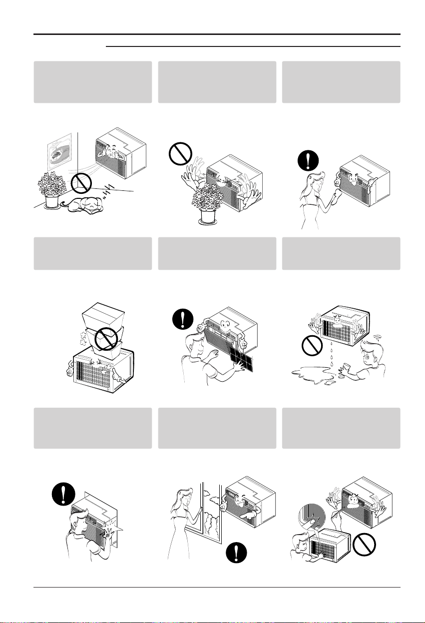
6 Aire Acondicionado
Safety Precautions
M
O
D
E
T
I
M
E
R
P
O
W
E
R
F
A
N
S
P
E
E
D
F
a
n
H
e
a
t
E
n
e
r
g
y
S
a
v
e
r
C
o
o
l
T
im
e
r
T
E
M
P
'
F
F
1
LO
W
F
2
H
IGH
Nosesubaalaunidad
interior/exterior ni coloque
objetos sobre la misma.
• Puede lesionarse al caerse
del aparato o al caerse los
objetos que haya colocado.
Inserte siempre el filtro
correctamente.
Límpielo cada dos semanas.
• El funcionamiento sin filtros
puede provocar fallos.
No beba el agua que drena
el aparato de aire
acondicionado.
No ponga plantas ni
animales en la trayectoria
que recorrerá el aire
caliente.
• Podría ocasionar lesiones.
No bloquee la entrada ni la
salida del flujo de aire.
• Puede causar una avería en
el aparato.
Utilice un paño suave para
limpiar. No utilice cera,
disolventes o detergentes
fuertes.
•
La apariencia del aparato de aire
acondicionado puede deteriorar,
cambiar el color o desarrollar
flujos en las superficies.
M
O
D
E
T
I
M
E
R
P
O
W
E
R
F
A
N
S
P
E
E
D
Fa
n
H
e
a
t
E
n
e
r
g
y
S
a
v
e
r
Co
o
l
Ti
m
e
r
T
E
M
P
'
F
F1
L
O
W
F
2
HIG
H
MO
DE
T
IME
R
PO
WER
F
A
N
S
P
E
E
D
F
a
n
H
e
a
t
E
n
e
rg
y
S
a
v
er
C
o
o
l
T
im
e
r
T
E
M
P
'
F
F
1
L
O
W
F
2
H
I
G
H
M
O
D
E
T
I
M
E
R
P
O
W
E
R
F
A
N
S
P
E
E
D
F
an
H
ea
t
E
n
e
r
g
y
S
a
v
e
r
C
o
o
l
T
i
m
er
T
E
M
P
'
F
F1 LO
W
F
2
HIG
H
Tenga cuidado para no
tocar los bordes
puntiagudos al instalar.
• Podría ocasionar lesiones.
Evite un enfriamiento
excesivo y ventile en
ocasiones.
• De lo contrario, podría dañar
su salud.
No introduzca la mano ni
barras en la entrada o salida
del aire durante el
funcionamiento del aparato.
• De lo contrario, podrían
ocurrir lesiones personales.
M
O
D
E
TIM
E
R
P
O
W
E
R
F
A
N
S
P
E
E
D
F
a
n
H
e
a
t
E
n
e
r
g
y
S
a
v
e
r
C
o
o
l
T
im
e
r
T
E
M
P
'
F
F
1
L
O
W
F
2
H
I
G
H
M
O
D
E
T
I
M
E
R
P
O
W
E
R
F
A
N
S
P
E
E
D
F
a
n
H
e
a
t
E
n
e
r
g
y
S
a
v
e
r
C
o
o
l
T
i
m
e
r
T
E
M
P
'
F
F
1
L
O
W
F2
H
I
G
H
M
O
D
E
T
I
M
E
R
P
O
W
E
R
F
A
N
S
P
E
E
D
F
a
n
H
e
a
t
E
n
e
r
g
y
S
a
v
e
r
C
o
o
l
T
i
m
e
r
T
E
M
P
'
F
F
1
L
O
W
F
2
H
I
G
H
■ Operación

ESPAÑOL
Manual del usuario 7
Antes de la Operación
1. Contactar un especialista para la instalación.
2. Coloque el enchufe correctamente.
3. No comparta la salida con otros artefactos.
4. No use un cable de extensión.
5. No arranque/detenga el funcionamiento enchufando/desenchufando el cable
de corriente eléctrica.
6. Si cuerda/tapón se daña, reemplace sólo con una parte autorizada.
1. Estar expuesto al flujo directo de aire por un período largo de tiempo puede
constituir un riesgo para su salud. No exponga a las personas, mascotas o
plantas al flujo directo por períodos largos de tiempo.
2. Debido a la posibilidad de una deficiencia de oxígeno, ventile la habitación
cuando utilice al mismo tiempo estufas u otros aparatos de calefacción.
3. No use este acondicionador de aire para propósitos determinados no
especificados (por ej.: preservar dispositivos de precisión, alimentos,
cachorros, plantas y objetos de arte). Usarlo de esta manera puede dañar
tales elementos.
1. No use agua para limpiar adentro del acondicionador. La exposición al agua
puede destruir la aislación y esto a su vez provocar una descarga eléctrica.
2. Cuando limpie la unidad, asegúrese que la corriente y el interruptor estén
desconectados. El ventilador gira a muy alta velocidad cuando está
funcionando. Existe la posibilidad de lesionarse si la energía se conecta
accidentalmente cuando esté limpiando las piezas internas de la unidad.
Para reparación y mantenimiento, contacte a su proveedor de servicio.
Antes de la Operación
Preparar para el funcionamiento
Uso
Limpieza y mantenimiento
Servicio
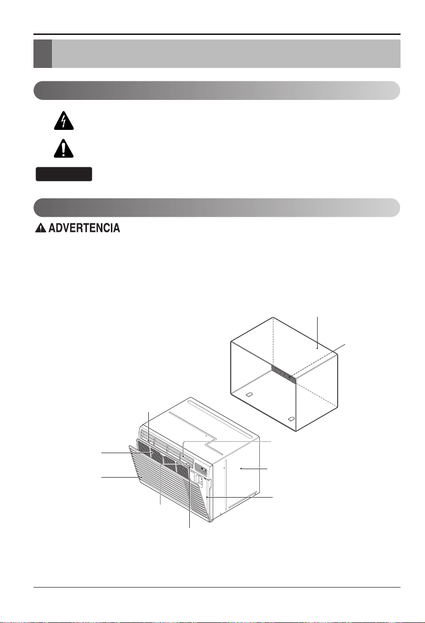
8 Aire Acondicionado
Este símbolo lo advierte de un peligro de accidente por
corriente eléctrica.
Este símbolo lo adiverte de un peligro que pueda causar un
daño del ventliador.
Este símbolo significa condicciones especiales.
CONSEJO
Introducción
Símbolos Utilizados en Este Manual
Características
Este aparato debería instalarse de acuerdo con las normas del Código Eléctrico Nacional.
Introducción
ARMARIO
REJILLA
FRONTAL
REJILLA DE ENTRADA
(Toma de aire)
FILTRO DE AIRE
DEFLECTOR HORIZONTAL DE AIRE
(Rejilla de ventilación vertical)
CONTROL DEL ORIFICIO DE VENTILACIÓN
DEFLECTOR VERTICAL DE AIRE
(Rejilla de ventilación horizontal)
DESCARGA
DE AIRE
MONTAJE DEL SOPORTE DE PARED
(Incluyendo rejilla posterior de aluminio)
EL SOPORTE DE PARED Y
LA REJILLA POSTERIOR
(incluido opcionalmente con su unidad)
EL UNIDAD
REJILLA POSTERIOR
(Rejilla posterior
de aluminio)
M
O
D
E
T
I
M
E
R
P
O
W
E
R
FA
N
S
P
E
E
D
F
a
n
H
e
a
t
E
n
e
r
g
y
S
a
v
e
r
C
o
o
l
T
i
m
e
r
T
E
M
P
'
F
F
1
L
O
W
F
2
H
I
G
H
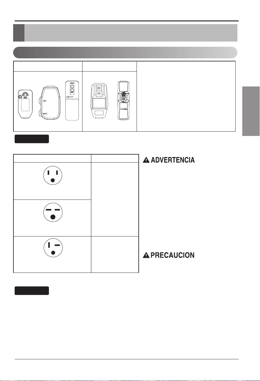
Manual del usuario 9
ESPAÑOL
Seguridad eléctrica
Seguraida Electrica
Datos Electricos
115V~ 230V~
El cable de alimentación puede incluir un
dispositivo interruptor de corriente. La
carcasa del enchufe cuenta con un botón de
prueba y otro de reinicio. El dispositivo debe
comprobarse periódicamente presionando
primero el botón TEST y después RESET.
Si el botón TEST no se desconecta o si el
botón RESET no permanece activo,
suspenda el uso del aire acondicionado y
póngase en contacto con un técnico de
servicio cualificado.
Utilice el enchufe de la pared Consumo de Energía
Standard 125V, enchufe de 3
Líneas de 15A, 125V AC
Standard 250V, enchufe de 3
Líneas de 15A, 250V AC
Standard 250V, enchufe de 3
Líneas de 20A, 250V AC
Utilice un fusible de
15AMP. o un
Interruptor de 15AMP.
Utilice un fusible de
20AMP. o un
Interruptor de 20AMP.
No presione nunca el botón de prueba durante el
funcionamiento, de lo contrario el enchufe podría
resultar dañado.
Este dispositivo contiene productos químicos,
incluyendo plomo, conocido en el estado de
California como producto cancerígeno y causante de
defectos de nacimiento y otros daños al sistema
reproductor.
Lávese bien las manos tras manipular el dispositivo.
No desmonte, modifique ni sumerja en agua este
enchufe.
Si el dispositivo se activara, deberá corregir la causa
antes de volver a utilizarlo.
Los hilos conductores dentro del cable están rodeados
por blindajes, que supervisan la corriente de fuga.
Estos blindajes no están puestos a tierra.
Examine periódicamente el cable en busca de
cualquier daño. No utilice este producto si los blindajes
resultaran expuestos.
Evite el riesgo de descargas eléctricas; esta unidad no
puede ser reparada por el usuario por ser resistente y
a prueba de alteraciones. Manipular la porción sellada
de la unidad anulará todas las garantías y quejas de
rendimiento. Esta unidad no está diseñada para su uso
como un interruptor de encendido-apagado.
La forma puede ser diferente según su modelo.
CONSEJO
NOUSECABLEDEEXTENSIÓNENUNIDADES
DE 208, 230, AND 208/230 VOLTIOS.
Todo el cableado deberá realizarse de acuerdo
con los códigos y reglamentos eléctricos
locales.
El cableado domésticodealuminiopodría
ocasionar problemas especiales. Consulte a un
electricista calificado.
CONSEJO
10 Aire Acondicionado
Seguridad eléctrica
IMPORTANTE
(FAVORLEA CON ATENCIÓN)
POR LA SEGURIDAD PERSONAL DEL USUARIO, ESTE
APARATO DEBE SER DEBÍDAMENTE NEUTRALIZADO.
El cordón de energíadeéste aparato esta equipado
con tres patas(cable a tierra). Utilice éste con un
enchufe de pared de tres salidas(a tierra) para
minimizar el peligro de choque eléctrico. El cliente
debe revisar el receptor de pared y el circuito por un
electricista calificado para asegurarse que la
recepción esta debidamente neutralizada.
NO CORTE O REMUEVA LA TERCERA PATA(GROUND)
DEL ENCHUFE.
A. SITUACIONES EN LAS CUALES EL APARATO
ES DESCONECTADO OCASIONALMENTE:
Debido al peligro potencial, nosotros no
recomendamos el uso de adaptadores. Sin embargo,
si usted desea utilizar un adaptador, una CONEXIÓN
TEMPORAL, puede ser
efectuada. Utilice adaptadores UL, disponibles en la
mayoría de los estable cimientos de
herramientas. La pata mas grande del adaptador
debe ser alineada con la pata mas grande del
interruptor para asegurarse una polarización
adecuada.
Adaptar la terminal del ground del adaptador a
la cubierta de la pared con un
tornillo no neutraliza el aparato a menos que la
cubierta del tornillo sea de metal, u no sea
insolada, y el receptor de pared este
neutralizado a través del alambrado del la casa.
El cliente debe hacer verificar el circuito por un
electricista calificado para asegurarse que el
receptor esta debidamente neutralizado.
Desconecte el cordóndeenergía del adaptador,
utilizado una mano en cada uno. De lo contrario, la
terminal del adaptador puede romperse. NO UTILICE el
aparato con un enchufe roto.
B. SITUACIONES EN LAS CUALES EL APARATO
ES DESCONECTADO CON
FRECUENCIA.
No utilice un adaptador en estas circunstancias.
Desconectar el cordóndeenergía con frecuencia lo
llevará al eventual rompimiento de la terminal de
neutralización. La saluda de energíadelapared
debe ser reemplazada por una salida de tres
patas(neutralizada).
USO DE EXTENSIONES
Debido al peligro potencial, no recomendamos la
utilizacióndeextensiones.Sinembargo,siusted
desea utilizar una extensión, utilice una
certificada por CSA/UL de tres alambres,
catalogada 15A, 125V.
Seguraida Electrica
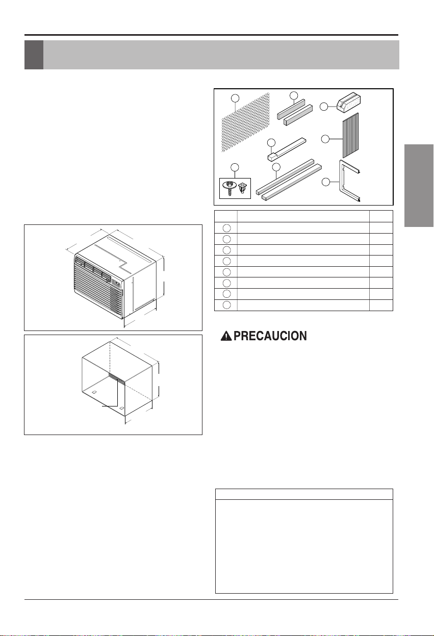
Manual del usuario 11
ESPAÑOL
Instalación
Instalación
Extraiga la lámina de embalaje del alojamiento del
aparato de aire acondicionado y la esquinera y cinta azul
del aparato de aire acondicionado.
REQUISITOS DE INSTALACIÓN
Si utiliza un alojamiento de pared existente, debe tomar sus
medidas.
Instale el nuevo aparato de aire acondicionado segúnestas
instrucciones de instalación para conseguir el mejor rendimiento.
Todos los alojamientos de pared utilizados para montar el nuevo
aparato de aire acondicionado deben tener su estructura en
buenas condiciones y tener una rejilla posterior para fijar con
seguridad el nuevo aparato de aire acondicionado. (FIG.1)
Con la caja protectora LGE puede(suministrada opcionalmente
con su unidad) mantener el mejor rendimiento del nuevo aire
acondicionado (FIG. 2)
SERVICIO ELÉCTRICO
Compruebe el servicio eléctrico disponible. La alimentación
disponible debe coincidir con la que se muestra en la etiqueta
identificativa de la unidad (que se encuentra en el lado izquierdo
del alojamiento).
Todos los modelos están equipados con un enchufe de servicio
de3clavijasconunatomadetierrapositivasegura.No
modifique el enchufe de ninguna manera. No utilice un enchufe
adaptador. Si su toma de corriente en la pared no coincide con
el enchufe, llame a un electricista cualificado para realizar los
cambios necesarios. GUARDE LA CAJA para el
almacenamiento y esta GUÍA DEL PROPIETARIO para futura
referencia. La caja es la mejor manera de almacenar la unidad
duranteelinviernoocuandonoseutilice.
EQUIPO DE INSTALACIÓN
14-
13
/
32
"
(366 mm)
24-
21
/
32
"
(626 mm)
18"(458 mm)
19-
21
/
32
"
(499 mm)
M
O
D
E
T
I
M
E
R
P
O
W
E
R
F
A
N
S
P
E
E
D
F
a
n
H
e
a
t
E
n
e
r
g
y
S
a
v
e
r
C
o
o
l
T
i
m
e
r
T
E
M
P
'
F
F
1
L
O
W
F
2
H
IG
H
1
4
5
6
7
3
2
8
2 opciones de tamaño
2 opciones de tamaño
Para evitar peligro de heridas personales, dañosalapropiedadoal
producto debido al peso de este aparato y a los bordes afilados que
pueden estar expuestos:
• Los aparatos de aire acondicionado de los que trata este manual
constituyen un peligro de peso excesivo. Se necesitan dos o más
personas para mover e instalar la unidad. Para evitar heridas o
problemas musculares, utilice técnicas adecuadas para elevar y
desplazar la unidad.
• Revise cuidadosamente la ubicación donde se instalará el aparato de
aire acondicionado. Asegúrese de que puede soportar el peso de la
unidad durante un periodo de tiempo prolongado.
• Maneje con cuidado el aparato de aire acondicionado. Lleve guantes
protectores siempre que levante o desplace la unidad. EVITE las aletas
afiladas de metal de las bobinas frontal y posterior.
• Asegúrese de que el aparato de aire acondicionado no cae al suelo
durantelainstalación.
HERRAMIENTAS NECESARIAS:
• Guantes ajustados
• Destornillador estándar
• Destornillador Phillips
• Cuchillo afilado
• Cinta para medir
•
Llave ajustable o de extremo
abiertode0,96cm(3/8de
pulgada)
• Llave articulada
• Llave de cabeza hexagonal de
0,64 cm (1/4 de pulgada) y
trinquete
• Taladro eléctrico
• Broca de taladro de 0,64 cm
(1/4 de pulgada)
FIG. 1
Aparato de aire acondicionado
ARTÍCULO
NOMBRE DE LAS PIEZAS
CANTIDAD
1 REJILLA DE PLÁSTICO 1
2 TIRAS DE AISLAMIENTO HORIZONTAL 2
3 TIRAS DE AISLAMIENTO LATERAL 2
4 BLOQUEDESOPORTE 2
5DEFLECTOR 1
6BASTIDORDEREBORDE 2
7 CALZO PARA AJUSTE 2
8
TUERCASDEPLÁSTICO Y TORNILLOS DE ARANDELA
4
15-
17
/
32
"
(394 mm)
16-
23
/
32
"
(425 mm)
25-
7
/
8
"
(656 mm)
Rejilla de metal
de aluminio foraminado
FIG. 2
Alojamiento de pared LGE
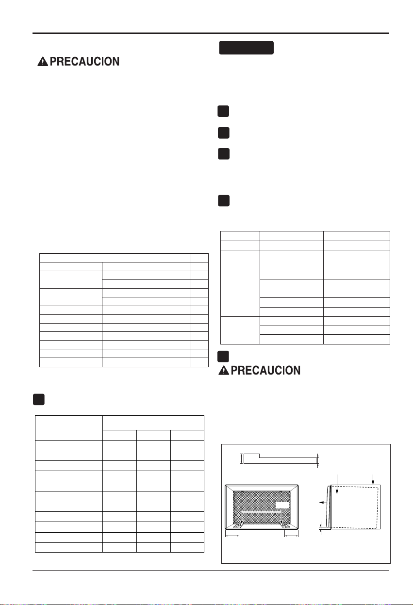
12 Aire Acondicionado
Instalación
INSTALACIÓN
• Si decide mantener el alojamiento de pared existente, tendrá
que ajustar la dirección de la rejilla en la parte posterior de la
ilustración del alojamiento de pared. Se recomienda el uso de
tenazas. Si NO ajusta la dirección, corre el riesgo de un
rendimiento pobre o de fallo del producto. Este hecho no está
cubierto bajo los términos de la garantíadeLGE.
ARTÍCULOSENELEQUIPODEINSTALACIÓN
Puede que no necesite todas las partes del equipo de
instalación. Tire las piezas que no utilice.
CÓMO INSTALARLO
Identifique el alojamiento existente en la pared antes de
instalar la unidad de la lista que se muestra a continuación
Todos los alojamientos de pared utilizados para montar el
nuevo aparato de aire acondicionado deben estar en buenas
condiciones estructurales y tener una rejilla posterior que se
una con seguridad al alojamiento o un flanco posterior que
sirva de tope al aparato de aire acondicionado,
Extraiga el antiguo aparato de aire acondicionado del
alojamiento de pared ya existente.
Limpie el interior del alojamiento de pared ya existente.
(No toque los sellados.)
El alojamiento de pared debe estar bien fijado a la pared
antes de instalar el aparato de aire acondicionado. Si fuera
necesario, utilice los clavos o tornillos para fijar el
alojamiento a la pared.
- Vuelva a pintar el alojamiento si fuera necesario.
Prepare el alojamiento de pared para la instalacióndela
unidad. Si pretende utilizar una caja de pared de la que ya
dispone y no es LGE, utilice el procedimiento B o C que se
muestra a continuación:
Instale la nueva unidad en el gabinete de pared.
Una vez finalizada la instalación, la unidad de repuesto
DEBE tener una pendiente hacia atráscomolaquese
muestra. Para alcanzar una pendiente del 1/4", retire la
parte posterior de las bandas de cuña de 11-13/16" y
acóplelas según se muestra a continuaciónenlafig.3.
Coloque la parte másaltadelacuñaenlapartefrontal
del pilar en la base del gabinete de pared.
CONSEJO
1
2
3
4
5
6
1/4"
Gabinete
de pared
FRONTAL
UNIDAD
COLOCACIÓN DE LA CUÑA INSTALACIÓN DE LA UNIDAD
1"de
alto
3/4"de alto
Cuña
6" 6"
FIG. 3
Se recomienda encarecidamente la extraccióndel
antiguo alojamiento en la pared y la instalacióndeun
nuevo alojamiento de pared Comfort-Aire.
Si decide mantener el alojamiento de pared
existente, tendrá que ajustar la dirección de la rejilla
en la parte posterior de la ilustración del alojamiento
de pared. Se recomienda el uso de tenazas. Si NO
ajusta la dirección, corre el riesgo de un rendimiento
pobre o de fallo del producto. Este hecho no está
cubierto bajo los términos de la garantía de Comfort-
Aire.
ARTÍCULO
Cantidad
Rejilla de plástico 3,81 x 2,54 x 210,03 cm (26
3
/4 x16
1
/2)1
Tiras de aislamiento horizontal
3,5 x 1,52 x 69,03 cm (1
3
/8 x
5
/8 x27
3
/16)1
3,5 x 3,5 x 69,03 cm (1
3
/8 x1
3
/8 x27
3
/16)1
Tiras de aislamiento lateral
3,5 x 2,03 x 153,035 (1
3
/8 x
3
/4 x61
1
/2)1
3,5 x 3,5 x 153,035 (1
3
/8 x1
3
/8 x61
1
/2)1
Bloque de soporte 8,89 x 3,5 x 10,94 cm (1
3
/4 x1
3
/8 x4
5
/16)2
Deflector 35,56 x 11,43 x 0,33 (14 x 4
1
/2 x
1
/8)1
Calzo para ajuste 33,02 x 2,54 x 2,03 (13 x 1 x
3
/4)2
Bastidor de reborde 2
Tornillo de arandela 4
Tuercas (plástico) 4
Parte posterior de la rejilla
1
Marca
Anchura
64,77
(25-1/2)
38,73
(15-1/4)
66,04(26) 39,70(15-5/8) 42,87(16-7/8)
65,48(25-7/8) 41,91(16-1/2)
43,51 o 58,42
(17-1/8 o 23)
68,58(27) 42,54(16-3/4)
65,73 (25-7/8)
39,44 (15-17/32) 42,46 (16-23/32)
67,94 (26-3/4)
40 (15-3/4) 38,1 (15)
65,40 (25-3/4) 42,87 (16-7/8) 47,32 (18-5/8)
68,58 (27)
42,54 (16-3/4) 42,54 (16-3/4)
42,54 o 50,16
(16-3/4 o 19-3/4)
40,64, 44,45, 55,88
(16, 17-1/2)
Altura Profundidad
Medidas del alojamiento de la pared
(pulgadas y centímetros)
White-Westinghouse
Frigidaire
Carrier (Serie 52F)
General Electric/Hotpoint
Whirlpool
Fedders/Emerson
LGE
Emerson/Fedders
Carrier (Serie 51S)
Friedrich
Procedimiento
Marca Profundidad
LGE
White-Westinghouse
Frigidaire Carrier
(52F series)
General Electric
/Hotpoint
Whirlpool
Carrier (51S series)
Fedders/Emerson
Emerson/Fedders
Friedrich
40,64, 44,45 0 55,88
(16, 17-1/2 o 22)
42,44 (16-23/32)
42,87 (16-7/8)
42,54 o 50,16 (16-3/4 o 19-3/4)
43,5 o 58,42 (17-1/8 o 23)
47,29 (18-5/8)
38,1 (15)
42,54 (16-3/4)
B
A
C
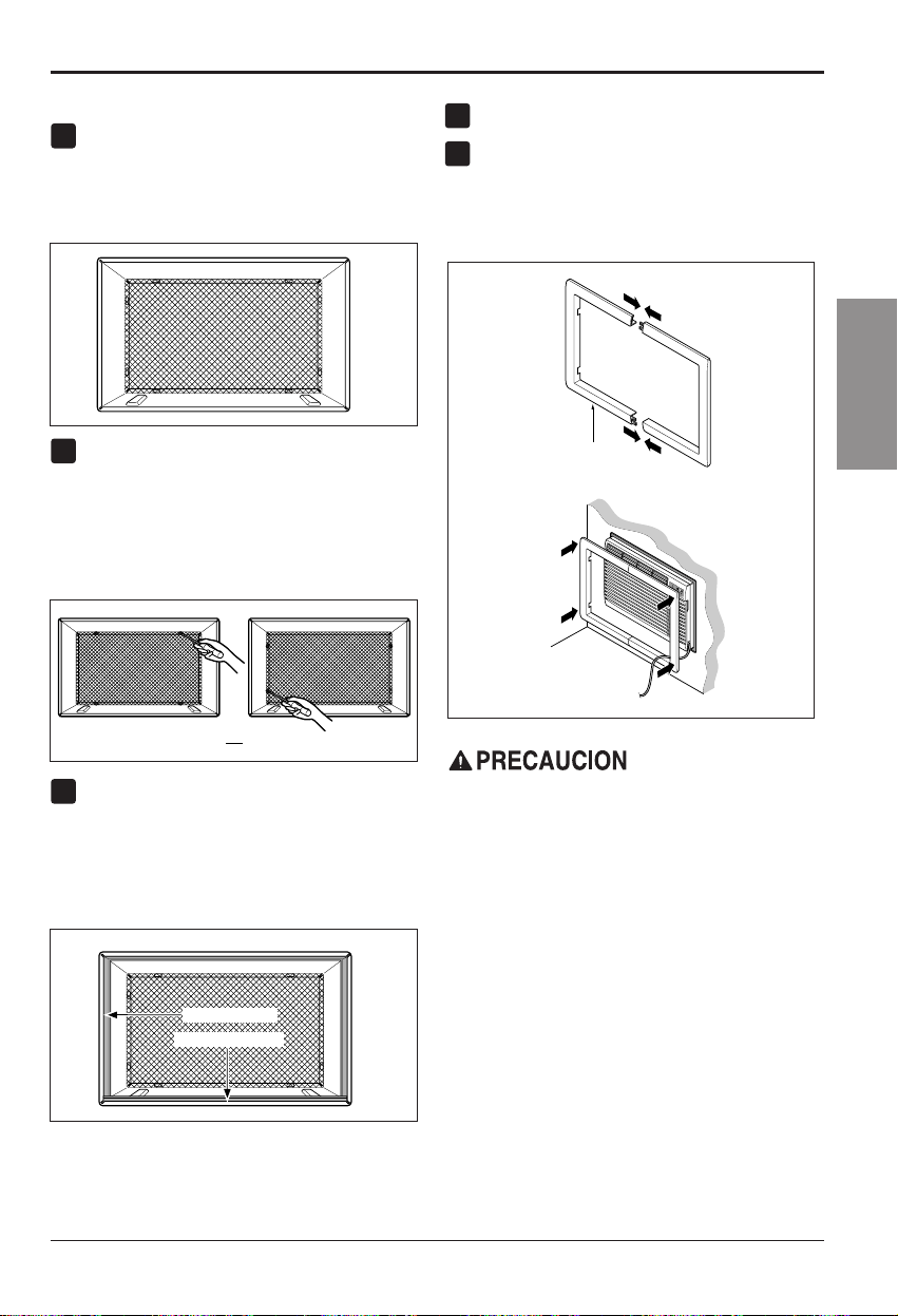
Manual del usuario 13
ESPAÑOL
Instalación
PROCEDIMIENTO A
Si está utilizando la nueva funda (suministrada
opcionalmente con su unidad), vaya directamente al paso 3.
En caso contrario, instale la rejilla plástica del equipo. Corte
la rejilla de plástico a 64,77 cm (25-1/2) de ancho y 38,74
cm (15-1/4) de alto. Coloque la rejilla de plástico en el
interior del alojamiento de pared, en el flanco posterior.
Apriete los 4 tornillos de arandela para fijar la rejilla
al alojamiento de pared. Si necesita tuercas de
plástico para montar la rejilla de plásticoenel
interior del alojamiento, hay tuercas de plásticoenel
equipo de instalación. Las tuercas se instalan desde
el interior del alojamiento y se introducen
apretándolas en los orificios cuadrados de los
flancos traseros.
Extraiga la parte posterior de la tira de Aislamiento
horizontal de 3,5 x 0,96 x 69,06 cm (1
3
/8 x
3
/5 x
27
3
/16)yfíjela a la parte inferior interna del
alojamiento según se muestra abajo. Extraiga la
parte posterior de la tira de Aislamiento lateral de
3,5 x 1,9 x 156,21 cm (1
3
/8 x
3
/4 x61
1
/2)yfíjela al
interior del alojamiento segúnsemuestraabajo.
Instale la nueva unidad en el alojamiento de la pared.
Para montar el reborde, inserte el saliente de cada
piezaenlaranuradelaotrapiezasegúnsemuestra
abajo. Deslice el reborde sobre la parte frontal del
aparato de aire acondicionado hasta que el reborde
esté unido a paño con el alojamiento segúnse
muestra a continuación.
FIG. 4
Aislamiento lateral
Aislamiento horizontal
FIG. 6
O
FIG. 5
1
2
3
4
5
Pared
Adorno (2ea)
M
O
D
E
T
I
M
E
R
P
O
W
E
R
F
A
N
S
P
E
E
D
F
a
n
H
e
a
t
E
n
e
r
g
y
S
a
v
e
r
C
o
o
l
T
i
m
e
r
T
E
M
P
'
F
F
1
L
O
W
F
2
H
I
G
H
FIG. 7
• Los aparatos de aire acondicionado de los que trata
este manual constituyen un peligro de peso excesivo.
Se necesitan dos o más personas para mover e
instalar la unidad. Para evitar heridas o problemas
musculares, utilice técnicas adecuadas para elevar y
desplazar la unidad.
• Al manejar el aparato de aire acondicionado, tenga
cuidado de evitar cortes de las aletas afiladas de
metal en las bobinas frontal y trasera.
• Asegúrese de que el aparato de aire acondicionado
no se cae durante la instalación.
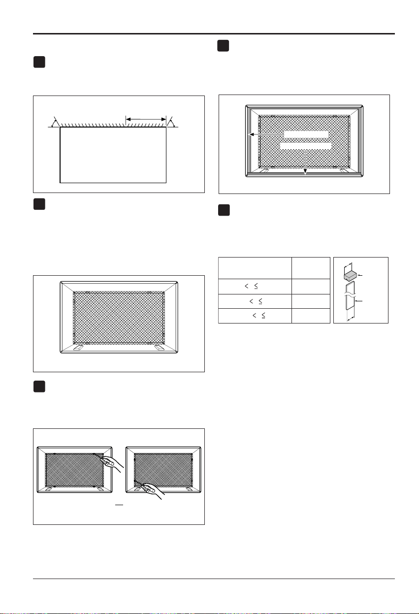
14 Aire Acondicionado
Instalación
PROCEDIMIENTO B
Coloque la dirección de la rejilla en la parte posterior
del alojamiento de la pared en un ángulo de 60° según
se muestra en la FIG 8.. Se recomienda el uso de
tenazas.
Si el alojamiento de pared está ya equipado con una
rejilla trasera, pase directamente al paso 4. Si el
alojamiento de la pared no tiene una rejilla posterior ni
un panel con lamas, instale la rejilla de plástico del
equipo de instalación. Corte la rejilla de plástico a unas
medidas de 64,77 cm (25-1/2) de ancho y 38,74 cm
(15-1/4) de alto. Coloque la rejilla de plásticoenel
interior del alojamiento de pared en el flanco posterior.
Cuando el alojamiento de la pared tiene una rejilla
posterior de panel con lamas, salte al paso 3 y
omita el paso 4. Coloque la rejilla de plástico en el
interior del alojamiento de pared en el flanco
posterior.
Extraiga la parte posterior de la tira de Aislamiento
horizontal de 3,5 x 1,60 x 69,06 cm (1
3
/8 x
5
/8 x27
3
/16)y
fíjela a la parte inferior interna del alojamiento segúnse
muestra abajo. Extraiga la parte posterior de la tira de
Aislamiento lateral de 3,5 x 1,9 x 156,21 (1
3
/8 x
3
/4 x61
1
/2)y
fíjela al interior del alojamiento segúnsemuestraabajo.
Cuando la profundidad del alojamiento existente es
igual o menor a 45,72 cm (18 pulgadas), pase
directamente al paso 7. En caso contrario, corte los
deflectores y los bloques de soporte segúnla
longitud “A” de la tabla que se muestra abajo.
1
4
2
3
FIG. 9
Aislamiento lateral
Aislamiento horizontal
FIG. 11
O
FIG. 10
Rejilla posterior
(Vista superior)
60°
60°
19,84 cm(7
5
/
16
")
FIG. 8
Profundidad "D" del alojamiento
de pared ya existente (pulgadas)
Longitud "A"
(pulgadas)
Bloque
de soporte
Deflector
A
A
3
/4
1-
3
/4
4
18 D 18-
5
/
8
18-
5
/
8
D 19-
3
/
4
19-
3
/
4
D 22
5
Coloque la rejilla de plástico
Apriete los tornillos
FIG. 12
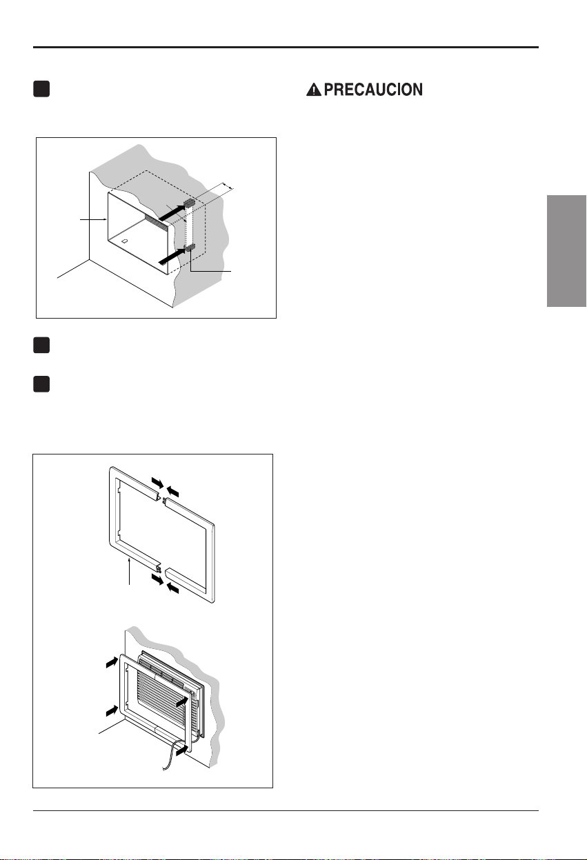
Manual del usuario 15
ESPAÑOL
Instalación
Pared
Alojamiento
de pared
Deflector
(7
5
/
16
")
Parte frontal
Bloque
de soporte
FIG. 13
7
8
PROCEDIMIENTO B
Extraiga la parte posterior de los bloques de soporte
yfíjelos en el interior del alojamiento de la pared
según se muestra en la FIG 13. Deslice el deflector
en las ranuras de los bloques de soporte.
Instale la nueva unidad en el alojamiento de la pared.
Para montar el reborde, inserte el saliente de cada
piezaenlaranuradelaotrapiezasegúnsemuestra
abajo. Deslice el reborde sobre la parte frontal del
aparato de aire acondicionado hasta que el reborde
esté unidoapaño con el alojamiento segúnsemuestra
a continuación.
6
Pared
Adorno (2ea)
M
O
D
E
T
I
M
E
R
P
O
W
E
R
F
A
N
S
P
E
E
D
F
a
n
H
e
a
t
E
n
e
r
g
y
S
a
v
e
r
C
o
o
l
T
i
m
e
r
T
E
M
P
'
F
F
1
L
O
W
F
2
H
I
G
H
FIG. 14
• Los aparatos de aire acondicionado de los que
trata este manual constituyen un peligro de peso
excesivo. Se necesitan dos o más personas para
mover e instalar la unidad. Para evitar heridas o
problemas musculares, utilice técnicas
adecuadas para elevar y desplazar la unidad.
• Al manejar el aparato de aire acondicionado,
tenga cuidado de evitar cortes de las aletas
afiladas de metal en las bobinas frontal y
trasera.
• Asegúrese de que el aparato de aire
acondicionado no cae al suelo durante la
instalación.
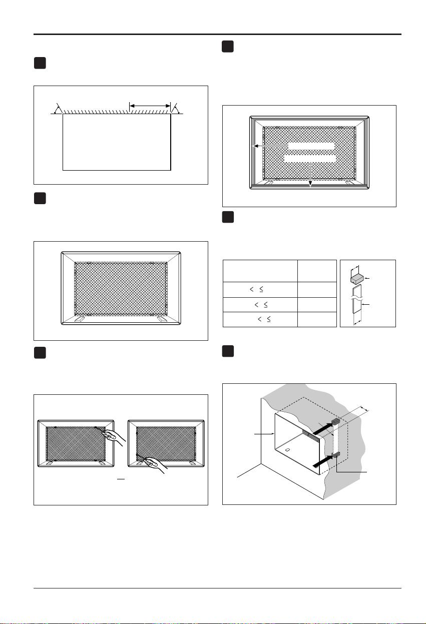
16 Aire Acondicionado
Instalación
PROCEDIMIENTO C
Coloque la dirección de la rejilla en la parte posterior del
alojamiento de la pared en un ángulo de 60° segúnse
muestra en la FIG 15. Se recomienda el uso de tenazas.
Si el alojamiento de la pared no tiene una rejilla
posterior o un panel con lamas, instale la rejilla de
plástico del equipo de instalación. Corte la rejilla de
plástico a unas medidas de 67,31 cm (26-1/2) de
ancho y 39,37 cm (15-1/2) de alto.
Cuando la profundidad del alojamiento existente es
igual o menor a 45,72 cm (18 pulgadas), pase
directamente al paso 7. Corte los deflectores y los
bloques de soporte según la longitud “A” de la tabla
que se muestra abajo.
Extraiga la parte posterior de la tira de Aislamiento
horizontal de 3,5 x 3,5 x 69,06 cm (13/8 x 13/8 x 273/16)
yfíjela a la parte inferior interna del alojamiento según
se muestra abajo. Extraiga la parte posterior de la tira de
Aislamiento lateral de 3,5 x 3,5 x 156,21 cm (13/8 x 13/8
x 611/2) y fíjela al interior frontal del alojamiento según
se muestra abajo.
Cuando la profundidad del alojamiento existente es
igual o menor a 45,72 cm (18 pulgadas), pase
directamente al paso 7. De otra manera, corte los
desviadores y los bloques del soporte de acuerdo a
la longitud “A” en el cuadro siguiente.
Extraiga la parte posterior de los bloques de soporte y
fíjelos al interior del alojamiento de la pared segúnse
muestra en la FIG 20. Deslice el deflector en las ranuras de
los bloques de soporte.
Profundidad "D" del alojamiento
de pared ya existente (pulgadas)
Longitud "A"
(pulgadas)
Bloque
de soporte
Deflector
A
A
3
/4
1-
3
/4
4
18 D 18-
5
/
8
18-
5
/
8
D 19-
3
/
4
19-
3
/
4
D 22
Pared
Alojamiento
de la pared
Deflector
Parte frontal
Bloque
de soporte
19,84 cm (
7
13
/
16
"
)
FIG. 20
FIG. 19
1
4
2
3
FIG. 16
Aislamiento lateral
Aislamiento horizontal
FIG. 18
O
FIG. 17
Rejilla posterior
(Vista superior)
60°
19,84 cm(7
13
/
16
")
60°
FIG. 15
5
6
Coloque la rejilla de plástico
Apriete los tornillos
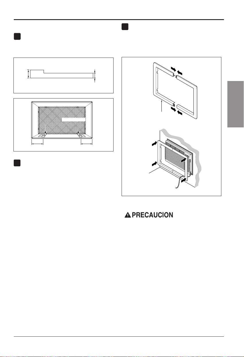
Instalación
Manual del usuario 17
ESPAÑOL
PROCEDIMIENTO C
Extraiga el refuerzo de las tiras de reborde 33,02 (13) y
fíjelas según se muestra abajo en la FIG 21. La parte
superior del reborde debe colocarse enfrente del
reborde en la base del alojamiento de la pared.
Instale la nueva unidad en el alojamiento de la
pared.
Para montar el reborde, inserte el saliente de cada
piezaenlaranuradelaotrapiezasegúnsemuestra
abajo. Deslice el reborde sobre la parte frontal del
aparato de aire acondicionado hasta que el reborde
esté unido a paño con el alojamiento segúnsemuestra
a continuación.
8
Pared
Adorno (2ea)
M
O
D
E
T
IM
E
R
P
OW
E
R
FA
N
SP
EE
D
F
a
n
H
e
a
t
E
n
e
r
g
y
S
a
v
e
r
C
o
o
l
T
i
m
e
r
T
E
M
P
'
F
F
1
L
O
W
F
2
H
I
G
H
FIG. 23
9
7
FIG. 21
1" High
3
/
4
" High
Reborde (2 cada)
6" 6"
FIG. 22
• Los aparatos de aire acondicionado de los que
trata este manual constituyen un peligro de peso
excesivo. Se necesitan dos o máspersonaspara
mover e instalar la unidad. Para evitar heridas o
problemas musculares, utilice técnicas
adecuadas para elevar y desplazar la unidad.
• Al manejar el aparato de aire acondicionado,
tenga cuidado de evitar cortes de las aletas
afiladas de metal en las bobinas frontal y
trasera.
• Asegúrese de que el aparato de aire
acondicionado no cae al suelo durante la
instalación.
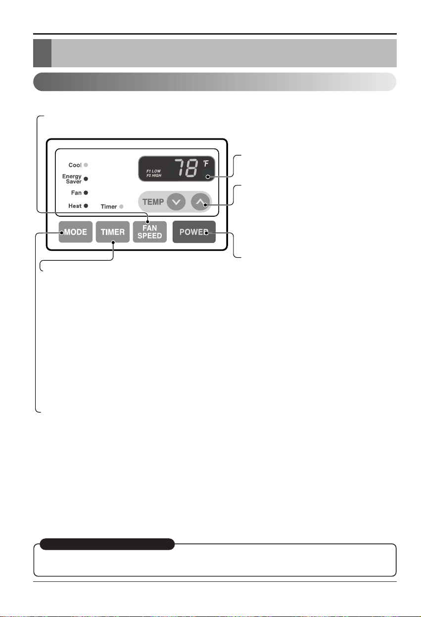
18 Aire Acondicionado
Instrucciones operativas
Instruccionnes de Funcionamiento
Controles
La apariencia de los controles será como uno de los siguientes.
RECEPTOR DE SEÑAL DEL MANDO
A DISTANCIA
ENERGÍA
MODO
- Presione este botón para cambiar el modo de funcionamiento de COOL
→ ENERGY SAVER → FAN → HEAT.
- COOL (fr
ío):
• El ventilador funciona continuamente en enfriamiento normal.
- ENERGY SABER (ahorro de energía):
• El ventilador para su funcionamiento cuando el compresor cesa de enfriar. El ventilador se encenderá y la unidad
comprobará la temperatura del aire de la habitación aproximadamente cada 3 minutos para determinar si es
necesario seguir enfriando.
- FAN (ventilador):
• Sólo está en funcionamiento el ventilador.
- HEAT (calor):
• El ventilador funciona continuamente on calentamiento normal.
TEMPORIZADOR
- HORA DE APAGADO
• Normalmente utilizará el tiempo de apagado mientras usted
duerme.
• Si la unidad está funcionando, utilice el temporizador para
fijar el número de horas hasta que se apague.
• Para su tranquilidad al dormir, una vez que el temporizador
esté configurado, el control de temperatura se elevará hasta
los 2° F tras 30 minutos y de nuevo tras otros 30 minutos.
• Presione el botón del temporizador para avanzar el ajuste de
1 hora → 2 horas → … → 12 horas máximo.
- HORA DE INICIO
• Si la unidad está apagada, utilice el temporizador para establecer el número de horas antes de iniciar la unidad.
• Presione el botón del temporizador para adelantar el ajuste de 1 hora → 2 horas → … → 12 horas máximo.
AJUSTE DE TEMPERATURA
• Utilice este botón para controlar
automáticamente la temperatura del
cuarto. La temperatura puede establecerse
dentro de una gama de 60° F a 86° F
mediante incrementos de 1° F.
• El ajuste se muestra en pantalla.
• Para ENCENDER el aire acondicionado,
presione este botón. Para APAGAR el aire
acondicionado, presione de nuevo el
botón.
• Este botón tiene prioridad sobre cualquier
otro botón.
VELOCIDAD DEL VENTILADOR
• Cada vez que presione este botón, el ajuste cambiará como sigue a continuación: {Alto[ F2 ] → Bajo[ F1 ] → Alto[ F2 ]}
REINICIO AUTOMÁTICO
Cuando se restablezca la alimentación después de un corte en el suministro, la unidad empezará a
funcionar con su último ajuste.
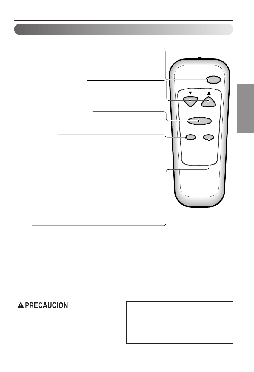
Instrucciones operativas
Manual del usuario 19
ESPAÑOL
Cuando el acondicionador de aire haya realizado su
operación ya sea de refrescar o calentar y se lo apaga
oselocolocaenlaposición "Fan" (ventilador) espere
por lo menos 3 minutos antes de volver a colocarlo en
la operacióndeenfriar.
Un ligero olor a calentamiento puede venir de la
unidad cuando por primera vez se coloca la llave en
HEAT (Calor) luego de que la temporada de
enfriamientos haya pasado. Este olor, causado por
pequeñas partículas de polvo sobre el calentador,
desaparecerá rápidamente. Es inofensivo.
Control remoto
El mando a distancia y el panel de control se parecerán a los de las siguientes imágenes.
Power
Temp
Fan Speed
Timer Mode
ENERGÍA
• Presione este botón para ENCENDER el aire acondicionado.
Para APAGAR el aire acondicionado vuelva a presionar el botón.
• Este botón tiene prioridad sobre cualquier otro botón.
AJUSTE DE TEMPERATURA
• Utilice este botón para controlar automáticamente la temperatura del cuarto.
La temperatura puede establecerse dentro de una gama de 60° F a 86° F por
incrementos de 1° F.
• El ajuste aparece en pantalla.
VELOCIDAD DEL VENTILADOR
• Cada vez que presione este botón, el ajuste cambiará como sigue a
continuación:
{Alto[ F2 ] → Bajo[ F1 ] → Alto[ F2 ]}
MODO
- Presione este botón para cambiar el modo de funcionamiento de COOL
→
ENERGY SAVER
→
FAN
→
HEAT.
- COOL (frío):
• El ventilador funciona continuamente en enfriamiento normal.
- ENERGY SABER (ahorro de energía):
• El ventilador para su funcionamiento cuando el compresor cesa de enfriar. El ventilador se encenderá y la
unidad comprobará la temperatura del aire de la habitación aproximadamente cada 3 minutos para determinar si
es necesario seguir enfriando.
- FAN (ventilador):
• Sólo está en funcionamiento el ventilador.
- HEAT (calor):
• El ventilador funciona continuamente on calentamiento normal.
TEMPORIZADOR
- HORA DE APAGADO
• Normalmente utilizará el tiempo de apagado mientras usted duerme.
• Si la unidad está funcionando, utilice el temporizador para fijar el número de
horas hasta que se apague.
• Para su tranquilidad al dormir, una vez que el temporizador esté
configurado, el control de temperatura se elevará hasta los 2° F tras 30
minutos y de nuevo tras otros 30 minutos.
• Presione el botón del temporizador para avanzar el ajuste de 1 hora → 2
horas → … → 12 horas máximo.
- HORA DE INICIO
• Si la unidad está apagada, utilice el temporizador para establecer el número
de horas antes de iniciar la unidad.
• Presione el botón del temporizador para adelantar el ajuste de 1 hora → 2
horas → … → 12 horas máximo.

20 Aire Acondicionado
Instrucciones operativas
Control de ventilación
Dirección del aire
Empuje la palanca hacia la posición “CLOSE” (cerrado) para
queelairedelahabitación se caliente, se enfríeo
simplemente recircule.
Empuje la palanca hacia la posición “OPEN” (abierto) para
expulsar el humo o el aire estancado de la habitación.
Obtendrá el máximo rendimiento de esta función si se utiliza
junto con la posiciónFANONLY(sólo ventilador).
Se puede controlar la dirección del aire ajustando las persianas
horizontales y verticales.
• AJUSTE DE LA DIRECCIÓN HORIZONTAL DEL
AIRE
La dirección horizontal del aire se ajusta moviendo la persiana
vertical. La palanca de la persiana vertical se ubica a la
derecha y a la izquierda de la descarga de aire.
• AJUSTE DE LA DIRECCIÓN VERTICAL DEL AIRE
La dirección vertical del aire se ajusta moviendo las persianas
horizontales.
M
O
D
E
T
IM
E
R
P
O
F
A
N
S
P
E
E
D
F
a
n
H
e
a
t
E
n
erg
y
S
ave
r
C
o
o
l
T
i
m
e
r
TEMP
F
1
L
O
W
F
2
H
I
G
H
PULL OPEN / PUSH CLOSE
M
O
D
E
T
IM
E
R
P
O
F
A
N
S
P
E
E
D
F
an
H
ea
t
E
n
e
r
g
y
S
a
v
e
r
C
oo
l
T
im
e
r
T
E
M
P
F
1
L
O
W
F
2
H
I
G
H
M
O
D
E
T
IM
E
R
P
O
W
E
R
F
A
N
S
P
E
E
D
F
a
n
H
e
a
t
E
n
e
r
g
y
S
a
v
e
r
C
o
o
l
T
i
m
e
r
T
E
M
P
'
F
F
1
L
O
W
F
2
H
I
G
H
M
O
D
E
T
I
M
E
R
P
O
W
E
R
F
A
N
S
P
E
E
D
Fan
Heat
E
n
e
r
g
y
S
a
v
e
r
Cool
Timer
T
E
M
P
'
F
F
1
L
O
W
F
2
H
I
G
H
Cómo Poner Las Baterias
1. Quite la tapa de la parte posterior del
telemando. Para ello haga deslizar la tapa
según la dirección del la flecha.
2. Introduzca las dos baterías, asegurándose de
que las direcciones (+) y (-) estén colocadas
correctament. Use baterías nuevas.
3. Volver a cerrar, resbalando la tapa hasta la
posición inicial.
• No utilice baterís recargables,
éstas son diferentes de forma,
de dimensiónyusorespectoa
las baterías secas usuales.
• Seque las baterías del
telemando cuando el
acondicionador no vaya a ser
usado durante un largo
período.

Manual del usuario 21
ESPAÑOL
M
O
D
E
T
I
M
E
R
P
O
W
E
R
F
A
N
S
P
E
E
D
F
a
n
H
e
a
t
E
n
e
r
g
y
S
a
v
e
r
C
o
o
l
T
i
m
e
r
T
E
M
P
'
F
F
1
L
O
W
F
2
H
I
G
H
M
O
D
E
T
IM
E
R
P
O
W
E
R
F
A
N
S
P
E
E
D
F
a
n
H
e
a
t
E
n
e
r
g
y
S
a
v
e
r
C
o
o
l
T
i
m
e
r
T
E
M
P
'
F
F
1
LO
W
F
2 H
IG
H
M
O
D
E
T
I
M
E
R
P
O
W
E
R
F
A
N
S
P
E
E
D
Fa
n
He
at
E
n
e
r
g
y
S
a
v
e
r
Co
o
l
T
ime
r
T
E
M
P
'
F
F
1
L
O
W
F
2
H
I
G
H
M
O
D
E
T
I
M
E
R
P
O
W
E
R
F
A
N
S
P
E
E
D
F
a
n
H
e
a
t
E
n
e
r
g
y
S
a
v
e
r
C
o
o
l
T
im
e
r
T
E
M
P
'
F
F
1
L
O
W
F
2
H
IG
H
Limpieza del filtro de aire
Como agregar la rejilla frontal al gabinete
Cuidado y Mantenimiento
Cuidado y Mantenimiento
APAGUE EL ACONDICIONADOR DE AIRE Y DESENCHÚFELODELAFUENTEDEPODER.
El filtro de aire debe ser controlado al menos dos veces al mes para
ver si es necesaria su limpieza.
Las partículas atrapadas en el filtro pueden acumularse y
bloquear el flujo del aire. Esto reduce la capacidad de
refrigeraciónytambién causa una acumulacióndehielo
en los sepentines de enfriamiento.
Si el filtro se inutiliza o se daña, debe ser reemplazado
inmediatamente. Filtros de repuesto están disponibles en la tienda
donde lo compró, el representante y en los centros de servicios
autorizados.
1. Abra la rejilla de entrada hacia abajo tirando de la parte superior de
la rejilla de entrada.
2. Quite el filtro de aire de la rejilla frontal tirando ligeramente del filtro
de aire.
3. Lave el filtro usando agua tibia por debajo de 40°C (104°F).
4. Sacuda suavemente el exceso de agua del filtro. Reemplace el filtro.
La rejilla frontal puede quitarse para su limpieza o para comprobar el modelo y el número de serie.
Para su seguridad, debe seguir el siguiente procedimiento para colocarla.
1. Quite la parte superior de la rejilla frontal de
la parte superior del gabinete.
2. Empuje los extremos frontales de la rejilla
hacia el gabinete a fin de insertar las
pestañas de la rejilla frontal en el gabinete.
3. Abra la rejilla de entrada.
4. Ajuste los tornillos a través de la rejilla frontal
enlaplacadelacajadecontrol.
5. Cierre la rejilla de entrada.

22 Aire Acondicionado
Cuidado y Mantenimiento
Funcionamiento normal
Mantenimiento
Funcionamiento defectuoso
• Puede que escuche un ruido metálico causado por el agua recogida y devuelta hacia el condensador en días
lluviosos o con alta humedad. Esta característica del diseño ayuda a eliminar la humedad y mejorar la eficiencia.
• Puede que escuche el chasquido del termostato cuando el compresor realiza ciclos de encendido y apagado.
• El agua se recogerá en la bandeja de la base en días lluviosos o con alta humedad. Puede que el agua rebose y
caiga desde la parte exterior de la unidad.
• Puede que el ventilador funcione aunque el compresor no lo haga.
• Para ahorrar tiempo y dinero, compruebe lo siguiente antes de llamar a un centro de asistencia
técnica autorizado. Para los modelos instalados en América del Norte: si necesita asistencia
técnicaopiezas,primerorealicelacomprobacióndeloindicadoacontinuación.
Problema Causas posibles Qué hacer
■ El acondicionador de aire está
desenchufadoonobien
enchufado
■ El fusible está fundido / el
disyuntor está interrumpido
■ Cortedecorriente
■ El dispositivo interruptor de
corriente está desconectado.
■ Elflujodeaireestá disminuido
■
Coloque el control de TEMPERATURA
en un número másalto.
■ El filtro de aire está sucio.
■ El acondicionador de aire se
acaba de encender.
■
El cuarto aúnestá caliente.
■ El aire fríoseescapa.
■ Los serpentines de
enfriamiento están congelados
■ Los serpentines de
enfriamiento están cubiertos de
hielo.
• Asegúrese que el enchufe está completamente
enchufado dentro del tomacorriente
• Compruebe el fusible /la caja del disyuntor y reemplace
el fusible o vuelva el disyuntor a su lugar.
• En el caso de un corte de corriente, coloque el control
de encendido en OFF. Cuando se haya restaurado la
corriente, espere durante 3 minutos para volver a hacer
funcionar el acondicionador de aire para prevenir la
sobrecarga del compresor.
• Presione el botón RESET situado en el enchufe del
cable de alimentación. Si el botón RESET no
permanece activo, suspenda el uso del aire
acondicionado y póngase en contacto con un técnico de
servicio cualificado.
• Asegúrese que no haya cortinas, persianas, muebles u
otros obstáculos frente al acondicionador de aire
•
GireelcontroldeTEMPERATURAaunnúmero más bajo.
•
Limpie el filtro al menos una vez cada dos semanas.
Refierase a la sección “Cuidado y Mantenimiento” del manual.
• Después que se enciende el acondicionador de aire,
debe darle un tiempo al acondicionador de aire para
enfriar la habitación.
• Cuando usted enciende el aire acondicionado debe
esperar un momento para que la habitaciónseenfrie.
• Busque alguna hornalla de resistencia encendida y el
aire fríovuelve.
• CIERRE la ventilación del acondicionador de aire
• Vea Aparece hielo sobre el acondicionador de aire abajo
• El hielo puede bloquear la corriente de aire e impedir
que el acondicionador de aire enfríe correctamente la
habitación.
• Ajustar el control de modo en ‘Ventilaciónalta’ o
‘Erfriamiento alto’ conlatemperaturaalta.
El acondicionador
de aire no
funciona para
nada
El acondicionador
de aire no enfría
Aparece hielo
sobre el
acondicionador
de airea

Manual del usuario 23
ESPAÑOL
Nota

24 Aire Acondicionado
Nota

Specifications and performance data subject to change without notice.
HEAT CONTROLLER, INC.
1900 WELLWORTH AVENUE • JACKSON, MICHIGAN 49203
THE QUALITY LEADER IN CONDITIONING AIR
P/NoPrinted in China
:
3828A21015Q