Loading ...
Loading ...
Loading ...
Version 10/12 - Page 5
WARNING
!
Whenbuildingacustomhood,
always follow all applicable
codes and standards.
TOOLS NEEDED FOR INSTALLATION
•SaberSaworJigSaw
•Drill
•11/4"WoodDrillBit
•Pliers
•PhillipsScrewdriver
(Magnetic head)
•WireStripperorUtilityKnife
•MetalSnips
•MeasuringTapeorRuler
•Level
•Pencil
•CaulkingGun
•DuctTape
PARTS SUPPLIED FOR INSTALLATION
•1LiteraturePackage
PARTS NEEDED FOR INSTALLATION
•2ConduitConnectors
•PowerSupplyCable
•ScrewstoReinforceAtttachment
•ScewsforFieldWiringBox
•1WallorRoofCap
•AllMetalDuctwork
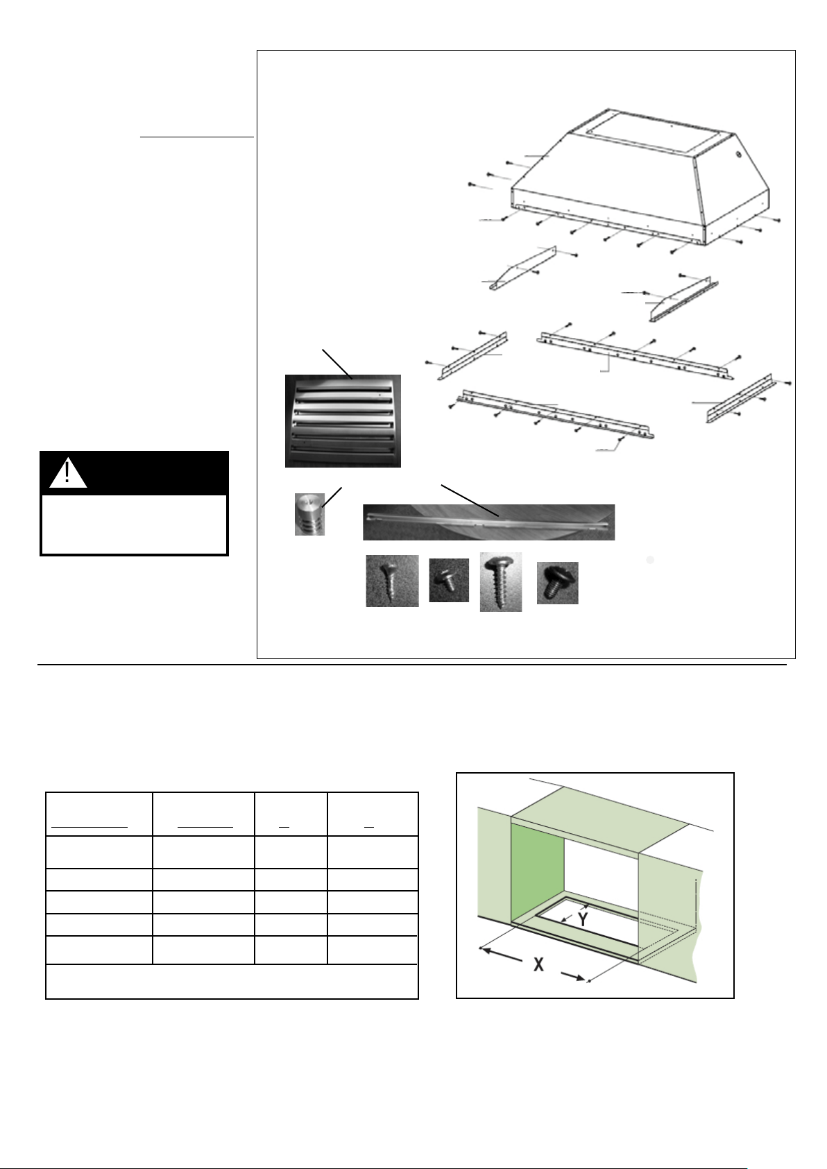
RANGEHOOD COMPONENTS
1. Hood body with lights and controls
2. Left Side Rail
3. Right Side Rail
4. (2) front / back trim
5. (2) left/right trim
6. grease lters (3 - 36/42" / 4 - 48")
7. lter knobs (6 - 36,42" / 8 - 48")
8. grease rail
9a. (4) side rail screws
9b. (16) trim screws
9c. (12) install screws
9d. (6 - 36,42", 8 - 48") lter knob screws
MAKING THE CABINET CUT OUT
FIGURE 1
FIGURE 2
Thishoodcanbeinstalleddirectlyintoacabinetwithoutalinerusing12ofthe9cscrews
(FIGURE1).Thelinerisbuiltintothehoodalready.
1.Cuttheopeninginthebottomofthecabinetaccordingtothechartbelow(FIGURE2,3)
Outside Hood
Dimension Model # X Y
36"x19"INPL3619SS343/4"193/4"
36"x22"INPL3622SS343/4"223/4"
42"x19"INPL4219SS403/4"193/4"
48"x19"INPL4819SS463/4"193/4"
48"x22"INPL4822SS463/4"223/4"
FIGURE 3
9a
9b
9c
9d
6
7
8
9c
9b
5
4
5
4
2
1
9a
3
Loading ...
Loading ...
Loading ...