Version 10/12 - Page 1
READ THESE INSTRUCTIONS BEFORE YOU START INSTALLING THIS RANGEHOOD
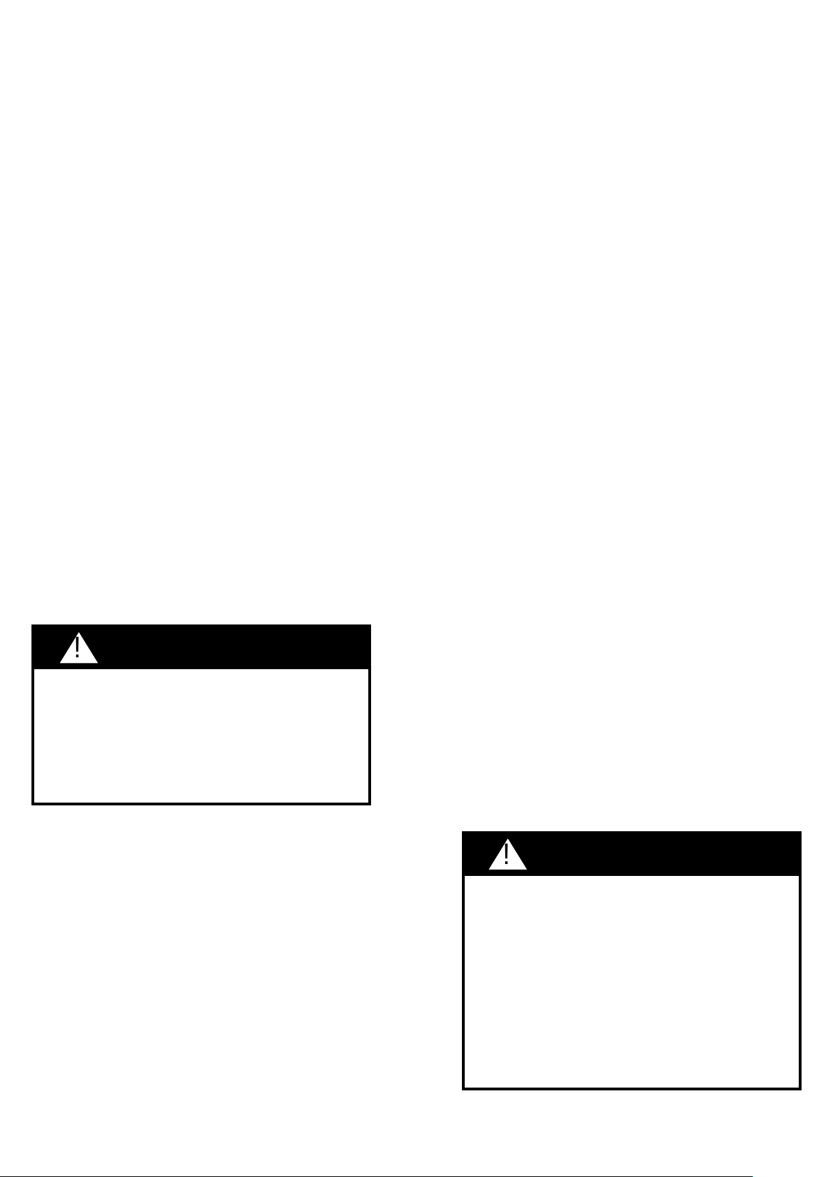
WARNING: - TO REDUCE THE RISK OF A RANGE TOP GREASE FIRE:
a) Never leave surface units unattended at high settings. Boilovers cause smoking and greasy spillovers that may
ignite. Heat oils slowly on low or medium setting.
b)AlwaysturnhoodONwhencookingathighheatorwhenambeingfood(i.e.CrepesSuzette,CherriesJubilee,
Peppercorn Beef Flambé).
c)Cleanventilatingfansfrequently.Greaseshouldnotbeallowedtoaccumulateonfanorlter.
d)Useproperpansize.Alwaysusecookwareappropriateforthesizeofthesurfaceelement.
WARNING: - TO REDUCE THE RISK OF INJURY TO PERSONS IN THE EVENT OF A RANGE TOP GREASE FIRE, OBSERVE THE
FOLLOWING (*):
a)SMOTHERFLAMESwithaclose-ttinglid,cookiesheet,ormetaltray,thenturnofftheburner.BECAREFULTOPREVENT
BURNS.IftheamesdonotgooutimmediatelyEVACUATEANDCALLTHEFIREDEPARTMENT.
b)NEVERPICKUPAFLAMINGPAN-Youmaybeburned.
c)DONOTUSEWATER,includingwetdishclothsortowels-aviolentsteamexplosionwillresult.
d)UseanextinguisherONLYif:
1.YouknowyouhaveaClassABCextinguisher,andyoualreadyknowhowtooperateit.
2.Thereissmallandcontainedintheareawhereitstarted.
3.Theredepartmentisbeingcalled.
4.Youcanghttherewithyourbacktoanexit.
(*)Basedon"kitchenresafetytips"publishedbyNFPA.
ALLWALLANDFLOOROPENINGSWHERETHERANGEHOODISINSTALLEDMUSTBESEALED.
Thisrangehoodrequiresatleast24"ofclearancebetweenthebottomoftherangehoodandthecookingsurfaceorcountertop.This
minimumclearancemaybehigherdependingonlocalbuildingcode.Forexample,forgasranges,aminimumof30"mayberequired.
Overheadcabinetsonbothsidesofthisunitmustbeaminimumof18"abovethecookingsurfaceorcountertop.Consultthecooktopor
range installation instructions given by the manufacturer before making any cutouts.
LISEZ BIEN CETTE FICHE AVANT D'INSTALLER LA HOTTE
AVERTISSEMENT - POUR MINIMISER LE RISQUE D’UN FEU DE GRAISSE SUR LA TABLE DE CUISSON : a) Ne jamais laisser un
élément de la table de cuisson fonctionner sans surveillance à la puissance de chauffage maximale; un renversement/déborde-
ment de matière graisseuse pourrait provoquer une inammation et le génération de fumée. Utiliser toujours une puissance de
chauffage moyenne ou basse pour le chauffage d’huile. b) Veiller à toujours faire fonctionner le ventilateur de la hotte lors d’une
cuisson avec une puissance de chauffage élevée ou lors de la cuisson d’un mets à amber (i.e. Crepes Suzette, Cherries Jubilee,
Peppercorn Beef Flambé). c) Nettoyer fréquemment les ventilateurs d’extraction. Veiller à ne pas laisser de la graisse s’accumuler
sur les surfaces du ventilateur ou des ltres. d) Utiliser toujours un ustensile de taille appropriée. Utiliser toujours un ustensile
de taille adapté à la taille de l’élément chauffant.
AVERTISSEMENT: - POUR PRÉVENIR LES BLESSURES EN CAS DE FEU SUIVRE LES RECOMMANDATIONS SUIVANTES: ÉTOUFFEZ
LE FEU avec un couvercle métallique et fermez le brûleur. Si le feu ne s'éteint pas tout de suite, QUITTEZ LES LIEUX ET APPELEZ
LES POMPIERS. NE TOUCHEZ JAMAIS UNE CASSEROLE EN FLAMMES. N'UTILISEZ JAMAIS DE L'EAU ou un torchon mouillé
pour éteindre le feu - ce qui pourrait causer une explosion de vapeur. N'utilisez un extincteur que si: 1. Vous avez un modèle
ABC et vous connaissez bien son mode d'emploi. 2. Le feu est petit et peu répandu. 3. Les pompiers sont déjà prévenus. 4.
Vous avez une sortie derrière vous.
TOUTEOUVERTUREDANSLEMUROULEPLANCHERÀPROXIMITÉDELAHOTTEDOITÊTRESCELLÉ
Gardez24po.dehauteurentrelebasdelahotteetlasurfacedecuisson.Cettehauteurminimumpeutêtreplushautesuivantlecode
municipal.Parexemple,lescuisinièresàgazpeuventrequérir30po.dehauteur.Lesarmoiresau-dessusnedépasserontpas13po.de
profondeur.Lesarmoiresau-dessusdechaquecôtédevrontêtreaumoinsà18po.au-dessusdelasurfacedecuisson.Consultezla
chetechniqueavantdedécouperlesarmoires.
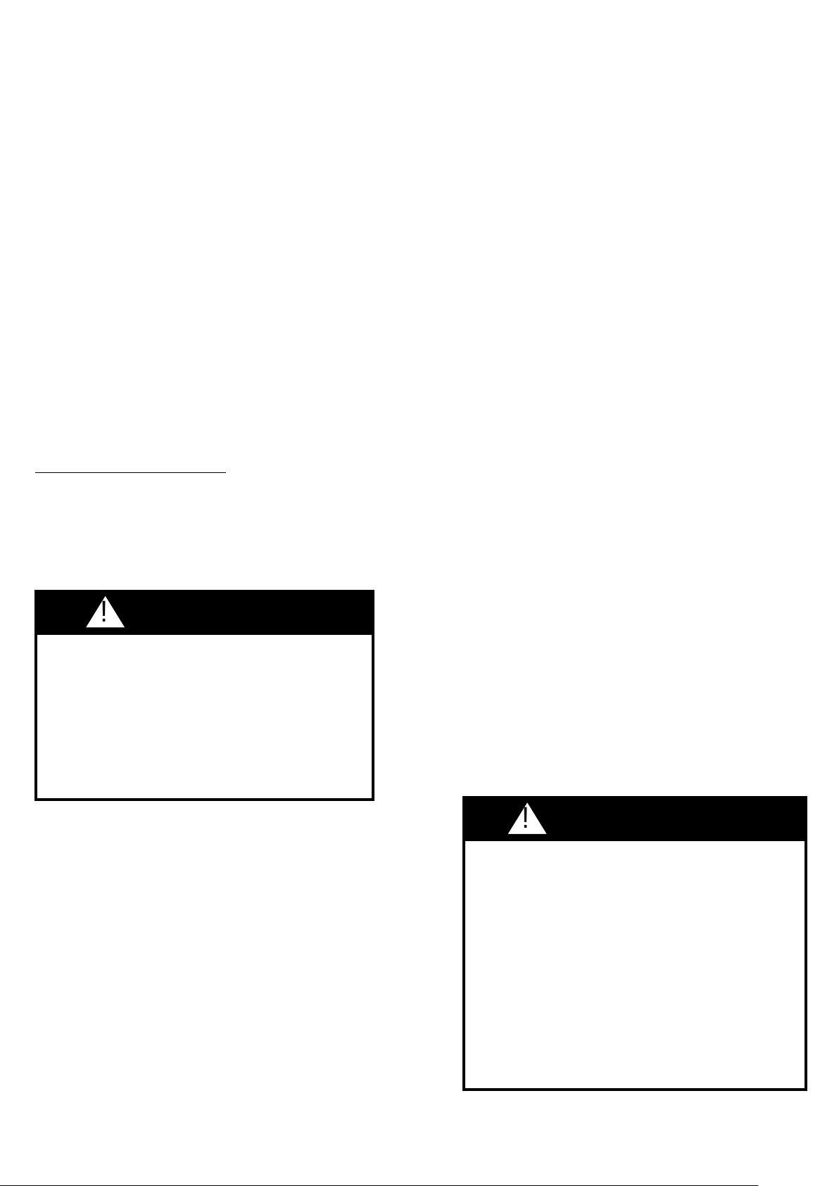
INCA PRO PLUS
Insert Hood
•InstallationInstructions
•UseandCareInformation
READ AND SAVE THESE INSTRUCTIONS
TheInstallermustleavetheseinstructionswiththehomeowner.
Thehomeownermustkeeptheseinstructionsforfuturereference
and for local electrical inspectors' use.
Version 10/12 - Page 2
VENTING REQUIREMENTS
Determinewhichventingmethodisbestforyourapplication.
Ductworkcanextendeitherthroughthewallortheroof.
Thelengthoftheductworkandthenumberofelbowsshouldbe
kepttoaminimumtoprovideefcientperformance.Thesize
oftheductworkshouldbeuniform.Donotinstalltwo
elbows together. Use duct tape to seal all joints in the ductwork
system.Usecaulkingtoseal exteriorwall oroor opening
around the cap.
Flexible ductwork is not recommended. Flexible ductwork
creates back pressure and air turbulence that greatly
reduces performance.
Makesurethereisproperclearancewithinthewalloroorfor
exhaustductbeforemakingcutouts.Donotcutajoistorstud
unlessabsolutelynecessary.Ifajoistorstudmustbecut,then
a supporting frame must be constructed.
FORMORESPECIFICDUCTWORKINFORMATION,GO
TOPAGE7.
WARNING - To Reduce The Risk Of Fire, Use Only Metal
Ductwork.
ELECTRICAL REQUIREMENTS
A120volt,60HzAC-onlyelectricalsupplyisrequiredonasepa-
rate 15 amp fused circuit. A time-delay fuse or circuit breaker
isrecommended.Thefusemustbesizedperlocalcodesin
accordancewiththeelectricalratingofthisunitasspecied
ontheserial/ratingplatelocatedinsidetheunitneartheeld
wiring compartment. THIS UNIT MUST BE CONNECTED
WITHCOPPERWIREONLY.Wiresizesmustconformtothe
requirementsoftheNationalElectricalCode,ANSI/NFPA70
-latestedition,andalllocalcodesandordinances.Wiresize
and connections must conform with the rating of the appliance.
Copiesofthestandardlistedabovemaybeobtainedfrom:
National Fire Protection Association
Batterymarch Park
Quincy,Massachusetts02269
This appliance should be connected directly to the fused
disconnect (or circuit breaker) through exible, armored or
nonmetallic sheathed copper cable. Allow some slack in the
cable so the appliance can be moved if servicing is ever nec-
essary.AULListed,1/2"conduitconnectormustbeprovided
ateachendofthepowersupplycable(attheapplianceand
atthejunctionbox)
•VentingsystemMUSTterminateoutsidethe
home.
•DONOTterminatetheductworkinanatticor
other enclosed space.
•DONOTuse4"laundry-typewallcaps.
•Flexible-typeductworkisnotrecommended.
•DONOTobstructtheowofcombustionand
ventilation air.
•Failuretofollowventingrequirementsmayresult
inare.
Whenmakingtheelectricalconnection,cuta11/4"holeinthe
wall. A hole cut through wood must be sanded until smooth. A
hole through metal must have a grommet.
WARNING - TO REDUCE THE RISK OF FIRE OR ELECTRIC
SHOCK, do not use this fan with any solid-state speed
control device.
WARNING - TO REDUCE THE RISK OF FIRE, ELECTRICAL
SHOCK, OR INJURY TO PERSONS, OBSERVE THE FOL-
LOWING: Use this unit only in the manner intended by
the manufacturer. If you have any questions, contact the
manufacturer.
Before servicing or cleaning unit, switch power off at service
panel and lock the service disconnecting means to prevent
power from being switched on accidentally. When the
service disconnecting means cannot be locked, securely
fasten a prominent warning device, such as a tag, to the
service panel.
WARNING - TO REDUCE THE RISK OF SHOCK: This fan
must be installed with an isolating wall control/switch.
CAUTION: For General Ventilating Use Only. Do Not Use To
Exhaust Hazardous or Explosive Materials and Vapors.
WARNING - TO REDUCE THE RISK OF FIRE, ELECTRICAL
SHOCK, OR INJURY TO PERSONS, OBSERVE THE FOL-
LOWING: Installation Work And Electrical Wiring Must
Be Done By Qualied Person(s) In Accordance With All
Applicable Codes And Standards, Including Fire-Rated
Construction.
Sufcient air is needed for proper combustion and exhaust-
ing of gases through the ue (chimney) of fuel burning
equipment to prevent backdrafting. Follow the heating
equipment manufacturer's guideline and safety standards
such as those published by the National Fire Protection
Association (NFPA), and the American Society for Heating,
Refrigeration and Air Conditioning Engineers (ASHRAE),
and the local code authorities.
When cutting or drilling into wall or ceiling, do not damage
electrical wiring and other hidden utilities.
Ducted fans must always be vented to the outdoors.
WARNING
•Electricalgroundisrequiredonthisrangehood.
•Ifcoldwaterpipeisinterruptedbyplastic,
nonmetallicgasketsorothermaterials,DONOT
use for grounding.
•DONOTgroundtoagaspipe.
•DONOThaveafuseintheneutralorgrounding
circuit. A fuse in the neutral or grounding circuit
could result in electrical shock.
•Checkwithaqualiedelectricianifyouareindoubt
as to whether the rangehood is properly grounded.
•DONOTusethisappliancewithanysolidstatefan
speed control device.
•Failuretofollowelectricalrequirementsmayresult
inare.
WARNING
For residential use only.
!
!
Cold Weather installations
Anadditionalbackdraftdampershouldbeinstalledtominimize
backwardcoldairowandanonmetallicthermalbreakshould
beinstalledtominimizeconductionofoutsidetemperatures
aspartoftheventsystem.Thedampershouldbeonthecold
airsideofthethermalbreak.Thebreakshouldbeascloseas
possible to where the vent system enters the heated portion
of the house.
Version 10/12 - Page 3
RÈGLEMENTS D'ÉVACUATION
Conrmerlasortied'évacuation-soitparlemur,soitparle
toit.
Utilisezunelongueurdetuyauterieminimaleaveclesmoindres
de coudes pour la plus grande efcacité. Le diamètre de
tuyauterie doit être uniforme. N'installez jamais 2 coudes
ensemble.Scellezbientouslesjointsavecunrubanadhésif
métalliqueàl'intérieuretscellezbienleclapetextérieuravec
du calfeutrage.
Utilisez un tuyau d'évacuation rigide lorsque possible. Un
tuyau exible égale deux fois plus qu'un tuyau rigide, ce qui
réduit la puissance d'évacuation. Un conduit d'évacuation
exible crée une contre-pression et une turbulence de l'air
qui réduisent considérablement la performance.
Veillezàcequel'espacepourletuyausoitample-ainsion
n'aurait pas besoin de découper les supports de mur intérieur.
Si ce découpage est nécessaire, veillez bien à ce qu'un
renforcement soit mis en place.
RÈGLEMENTSD'ÉVACUATIONADDITIONELL-PAGE15
AVERTISSEMENT - Pour Ne Pas Risquer Un Feu, Utilisez
Seulement Les Matériaux Métalliques.
Faitesuntroude11/4po.danslemur.S'ils'agitd'untrouen
bois-sablez-lebien,tandisqu'untroupassantparlemétal
demande un bouche-trou.
AVERTISSEMENT - POUR RÉDUIRE LE RISQUE D'INCENDIE
OU DE CHOC ELECTRIQUE, ne pas utiliser ce ventilateur
en conjonction avec un dispositif de réglage de vitesse à
semi-conducteurs.
AVERTISSEMENT – POUR MINIMISER LES RISQUES
D’INCENDIE, CHOC ÉLECTRIQUE OU DOMMAGES
CORPORELS, OBSERVER LES PRESCRIPTIONS
SUIVANTES: Suivez les recommandations du fabricant et
entre en communication avec lui pour toute information.
Fermez le courant avant tout entretien et veillez a ce qu'il
reste fermé. Si on ne peut pas verrouiller le panneaux
du service électrique, afchez un avis de danger sur la
porte.
AVERTISSEMENT – POUR MINIMISER LE RISQUE DE CHOC
ÉLECTRIQUE: Ce ventilateur doit être installé avec un mur
d'isolement iterrupteur de commande.
AVIS: Pour L'évacuation Générale - Veillez à Ne Pas Evacuer
Des Matériaux Ou Vapeurs Explosif.
AVERTISSEMENT – POUR MINIMISER LES RISQUES
D’INCENDIE, CHOC ÉLECTRIQUE OU DOMMAGES
CORPORELS, OBSERVER LES PRESCRIPTIONS
SUIVANTES: L'installation Et Le Raccordement Electrique
Doivent Se Faire Par Un Technicien Qualié Selon Tous
Les Codes Municipaux.
An d'obtenir un rendement maximal en ce qui a trait à la
combustion ainsi qu'à l'évacuation des gaz par la conduite
de cheminée, une bonne aération est nécessaire pour
tous les appareils à combustion. Suivez les conseils et
mesures de sécurité du fournisseur tels que ceux publiés
par l'Association Nationale de la Sauvegarde contre
l'Incendie et l'Association Américaine d'Ingénieurs de
Chauffage, Frigorifaction et Air Climatisé ainsi que les
codes municipaux.
En perçant un mur veillez à ne pas perforer un autre l
électrique.
Une ventilateur à évacuation extérieure doit être raccordée
à l'extérieur.
AVERTISSEMENT
•Lesystèmed'évacuationDOITsortiràl'extérieur.
•N'ÉVACUEZPASleconduitsoitdansune
mansarde soit dans un espace enfermé.
•N'UTILISEZPASunclapetdeséchoirà4pouces.
•N'utilisezpasunconduitexible.
•N'ENCOMBREZPASlacirculationd'air.
•Fautedesuivrecetavertissementpourrait
occasionner un feu.
FICHE TECHNIQUE ÉLECTRIQUE
Leraccordementélectriquedoitsefaireavecuncircuitséparé
de15ampèresfusibleà120V,60Hz,courantalternant.On
recommande un coupe-circuit. La taille du fusible doit se
conformer aux codes municipaux suivant la spécication
électriquesurlaplaqueintérieure.Lediamètreduldevraaussi
seconformerauxrèglementsducodenationalélectrique,ANSI/
NFPA70-ainsiqu'auxrèglementslocauxetlesspécications
decetappareil.Onpeutobtenircesinformationschez:
l'Association Nationale de la Prévention du Feu
Batterymarch Park
Quincy,Massachusetts02269
Raccordezcetappareildirectementaucoupe-circuitavecunl
exibllecouvertencuivreenlaissantunpeudelâchementdans
lelpourpermettreledéplacementdel'appareil.Veillezace
qu'uncontactd'undemi-pouce(1/2po.)soitinstalléàchaque
boutdel(soitàl'appareilainsiqu'àlaboiteàfusible).
•Unepriseàterreestnécessairepoutcettehotte.
•N'utilisezpasuntuyauàl'eaufroidepourlamise
àterres'ilestbranchéàunjointplastique,non-
métalliqueouautre.
•NEJOIGNEZPASlamiseàterreàconduitdegaz.
•N'INSTALLEZPASunfusibledanslecircuitde
miseàterre-cequipeutcauserunesecousse
électrique.
•Vériezavecunélectriciencertiéàcequelahotte
soitbienmiseàterre.
•Fautedesuivrecesrecommandationspourrait
occasionner un feu.
AVERTISSEMENT
Uniquement pour usage menager.
!
!
Installations pour régions à climat froid
Ondevraitinstallerunclapetantireuxadditionnelpourminimiserle
reuxd'airfroid,etincorporerunélémentnonmétalliqued'isolation
thermiquepourminimiserlaconductiondechaleurparl'intermédiaire
duconduitd'évacuation,del'intérieurdelamaisonàl'extérieur.Le
clapetanti-reuxdoitêtreplacéducôtéairfroidparrapportàl'élément
d'isolationthermique.L'isolantthermiquedoitêtreaussiprocheque
possibledel'endroitoùlesystèmed'évacuations'introduitdansla
partie chauffée de la maison.
Version 10/12 - Page 4
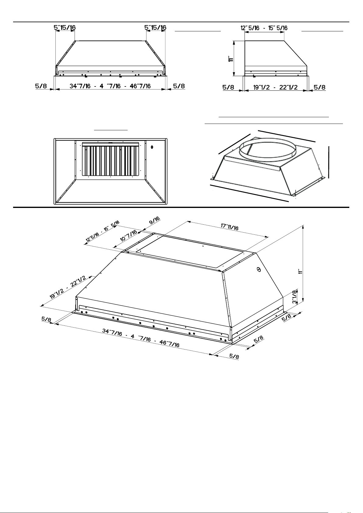
RANGEHOOD DIMENSIONS / DIMENSIONS DE LA HOTTE
Pre-Planning Your Installation -
Important:Therecommendedheighttoinstallthishoodoffthecooktopisa
minimumof30”formaximumeffectiveness.Alsoconsultthecooktopmanufacturer’srecommendation.
Planiez votre installation-Important:Lahauteurrecommandéepourinstallercettehotteau-dessusdela
surfacedecuissonestd’unminimumde30”pourunmaximumd’efcacité.Deplus,nousvousrecommandons
consulter le manuel de recommandations du fabricant de la surface de cuisson.
0
22 9/16” - 28 9/16” - 34 9/16”
0
22 9/16” - 28 9/16” - 34 9/16”
Note: Total width and depth of the cabinet bottom needs to include 5/8" trim on all sides of the
hood. A total of 20 3/4" or 23 3/4" depth (19 or 22" hood) and 35 11/16" , 41 11/16", 47 11/16" width
(36, 42, or 48" wide hoods)
Note : La largeur et la profondeur totales du fond de coffret doit inclure 5/8" ; équilibre de tous les
côtés du capot. Un total de 20 3/4" ; ou 23 3/4" ; profondeur (19 ou 22" ; capot) et 35 11/16" ; , 41
11/16" ; , 47 11/16" ; largeur (36, 42, ou 48" ; capots larges)
6”
11 1/2”
17”
11 1/4”
SIDE / DE CÔTÉ
FRONT / DESSUS
TOP / AVANT
DUCT TRANSITION (for 1200 cfm #IB1200)
LA TRASITION DE CONDUIT (pour 1200 cfm #IB1200)
Version 10/12 - Page 5
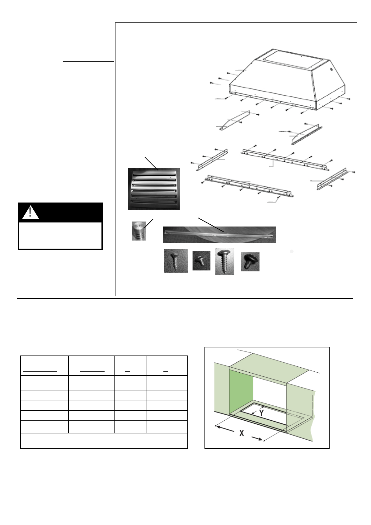
WARNING
!
Whenbuildingacustomhood,
always follow all applicable
codes and standards.
TOOLS NEEDED FOR INSTALLATION
•SaberSaworJigSaw
•Drill
•11/4"WoodDrillBit
•Pliers
•PhillipsScrewdriver
(Magnetic head)
•WireStripperorUtilityKnife
•MetalSnips
•MeasuringTapeorRuler
•Level
•Pencil
•CaulkingGun
•DuctTape
PARTS SUPPLIED FOR INSTALLATION
•1LiteraturePackage
PARTS NEEDED FOR INSTALLATION
•2ConduitConnectors
•PowerSupplyCable
•ScrewstoReinforceAtttachment
•ScewsforFieldWiringBox
•1WallorRoofCap
•AllMetalDuctwork
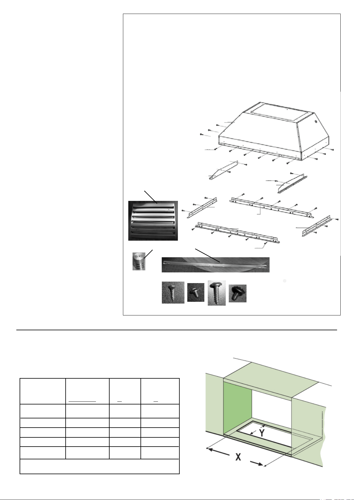
RANGEHOOD COMPONENTS
1. Hood body with lights and controls
2. Left Side Rail
3. Right Side Rail
4. (2) front / back trim
5. (2) left/right trim
6. grease lters (3 - 36/42" / 4 - 48")
7. lter knobs (6 - 36,42" / 8 - 48")
8. grease rail
9a. (4) side rail screws
9b. (16) trim screws
9c. (12) install screws
9d. (6 - 36,42", 8 - 48") lter knob screws
MAKING THE CABINET CUT OUT
FIGURE 1
FIGURE 2
Thishoodcanbeinstalleddirectlyintoacabinetwithoutalinerusing12ofthe9cscrews
(FIGURE1).Thelinerisbuiltintothehoodalready.
1.Cuttheopeninginthebottomofthecabinetaccordingtothechartbelow(FIGURE2,3)
Outside Hood
Dimension Model # X Y
36"x19"INPL3619SS343/4"193/4"
36"x22"INPL3622SS343/4"223/4"
42"x19"INPL4219SS403/4"193/4"
48"x19"INPL4819SS463/4"193/4"
48"x22"INPL4822SS463/4"223/4"
FIGURE 3
9a
9b
9c
9d
6
7
8
9c
9b
5
4
5
4
2
1
9a
3
Version10/12-Page6
INSTALLATION
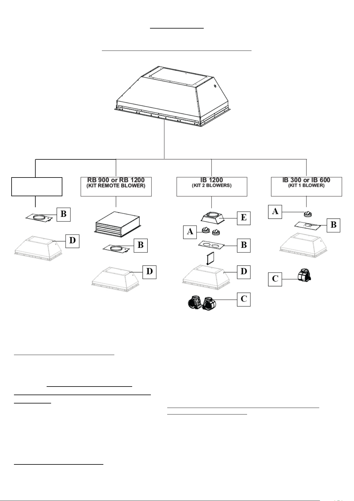
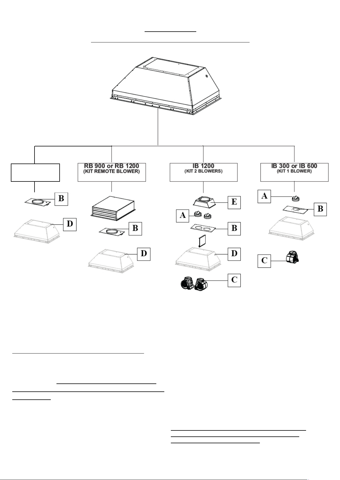
COMBINATIONS HOOD AND MOTOR KITS
CHOOSE A BLOWER FOR YOUR HOOD
After choosing the hood width and depth for your cooking
needs, next choose the type of blower appropriate for
your cooking.
NOTE: no other blower is
compatible with this hood, except for the
kits below.
# IB300 - Internal Blower Kit 300 cfm
# IB600 - Internal Blower Kit 600 cfm
# IB1200 - Internal Blower Kit 1200 cfm
# RB900 - Remote Blower Kit 900 cfm
# RB1200 - Remote Blower Kit 1200 cfm
# INLBKIT - In Line Blower Kit
(supply own in-line blower)
OPTIONAL ACCESSORIES AVAILABLE
• *Charcoal Filter
*itishighlyrecommendedthatprofessionalstylecookingalwaysbe
ventedtotheoutside;forrecirculatinginstallationsonly,someductworkis
requiredtoexhausttheunitoutofthecabinet.Replaceasneededwiththe
same model
part # FILTER1
NOTE: The charcoal lter kit for use with the 300 / 600
cfm internal blower kit ONLY
CAUTION - To reduce risk of re and electric shock, install this rangehood only with: Remote blower manufacturer by Faber
models RB900 and RB1200 or Integral blower manufactured by Faber models IB300 or IB600 or IB1200 or with INLBKIT and
generic in-line blower rated max 4.2 A suitable for use with solid state variable speed control
INLBKIT
Version10/12-Page7
PLAN YOUR DUCTWORK
Toensurethattheblowerperformstoitshighest
possiblecapacity,ductworkshouldbeasshort
and straight as possilbe.
For satisfactory performance the duct run
shouldnotexceed50 equivalent feet if ducted
usingtherequiredminimum6"roundduct.For
10"roundducting with the 1200 cfminternal
motoror 900/1200 remoteblower,theduct
runshouldnotexceed75 equivalent feet.
Calculatethelengthoftheductworkbyadding
theequivalentfeetinFIGURE 5 for each piece
ofductinthesystemAnexampleisgivenin
FIGURE 6.
For best results, use no more than three 90°
elbows. Make sure that there is a minimum of
24" of straight duct between elbows if more
than one is used. Do not install two elbows
together. If you must elbow right away, do it
as far away from the hood's exhaust opening
as possible.
9FeetStraightDuct
2-90˚Elbows
WallCap
TotalSystem
9.0feet
10.0 feet
0.0 feet
19.0feet
FIGURE 6
3.0 feet
5.0 feet
12.0 feet
0.0 feet
45˚Elbow
90˚Elbow
90˚FlatElbow
WallCap
FIGURE 5
FIGURE 4
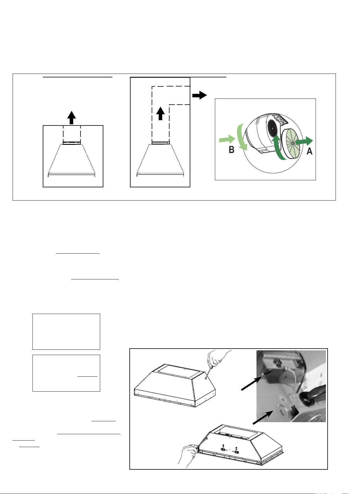
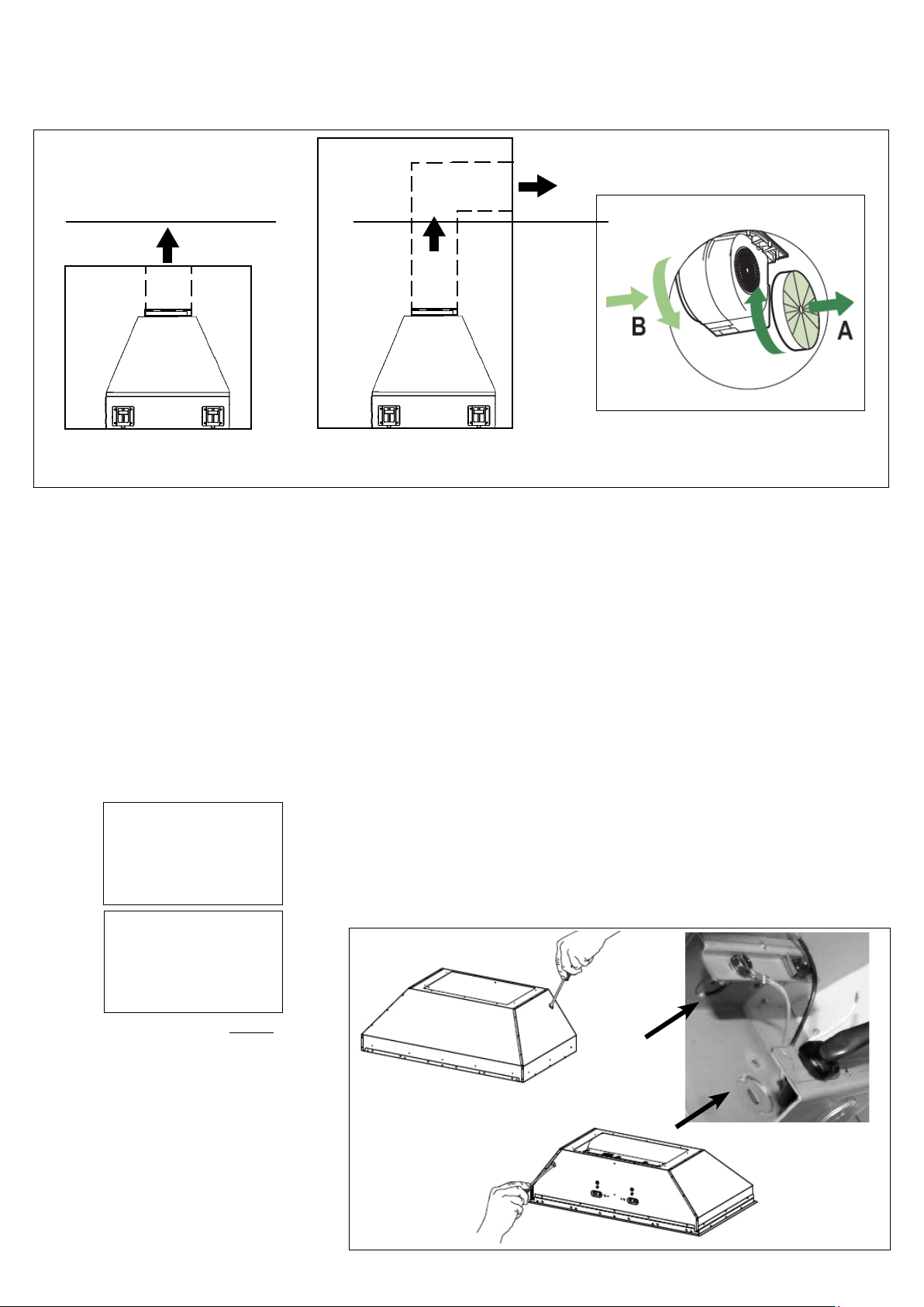
RECIRCULATING INSTALLATIONS
ITISHIGHLYRECOMMENDEDTHATPROFESSIONALSTYLECOOKINGALWAYSBEVENTEDTOTHEOUTSIDE.Forrecirculating
installations (FIGURE 4),Charcoal Filtersarenecessary.Removeallgreaseltersandsetaside.Attachonecharcoalltertoeachend
oftheblower.Eachcharcoallterattachestothegridonthesideoftheblower.Rotatethelterclockwisetoinstallandcounterclockwise
to remove (FIGURE 4A).Replaceallgreaselters.Recirculatinginstallationsalsorequiresomeductworktodiverttheairoutofthetopor
faceorsideofthecabinetorcustomhoodoroutoftheside/faceofthesoftandbackintothekitchen.Installatleast15"ofverticalrunof
metal duct (FIGURE 4) attheairoutlet.Runtheductverticallyandsecureitattherelevantopeningpreviouslycutoutatthetoporsideof
thecabinetorsoft.Ametalductcovergrilleisalsorecommended.Theductworkmustnotterminateinsidethecabinetorcustomhood.
cabinet
or
custom
hood
ceiling
duct
work
duct
work
ceiling
inca pro plus
cabinet
or
custom
hood
MAKE YOUR CUT-OUTS
1. Disconnectandmovefreestandingrangefromcabinetopeningtoprovideeasieraccess
touppercabinetorcustomhood.Putathick,protectivecoveringovercooktop,set-inrange
or countertop to protect from damage or dirt.
2. Determineandmakeallnecessarycutsinthewalland/orceilingfortheductwork.Install
the ductwork before the rangehood.
3. DeterminetheproperlocationforthePowerSupplyCable.Usea11/4"DrillBittomake
thishole.Installthecable.Usecaulkingtosealaroundthehole.DONOTturnonthe
power until installation is complete.
4.Choosetheknockoutholetoremoveforinstallingthepowercable.Useascrewdriver
tosnapofftheknockoutcovering.(FIGURE7showsinsidethewiringboxandoutside)
FIGURE 4A
inca pro plus
FIGURE 7
FOR ALL INSTALLATIONS
REMOVE ALL WHITE PLASTIC PROTECTIVE COVERING FROM HOOD, SIDE RAILS,
TRIM, GREASE RAILS AND GREASE FILTERS
Version 10/12 - Page 8
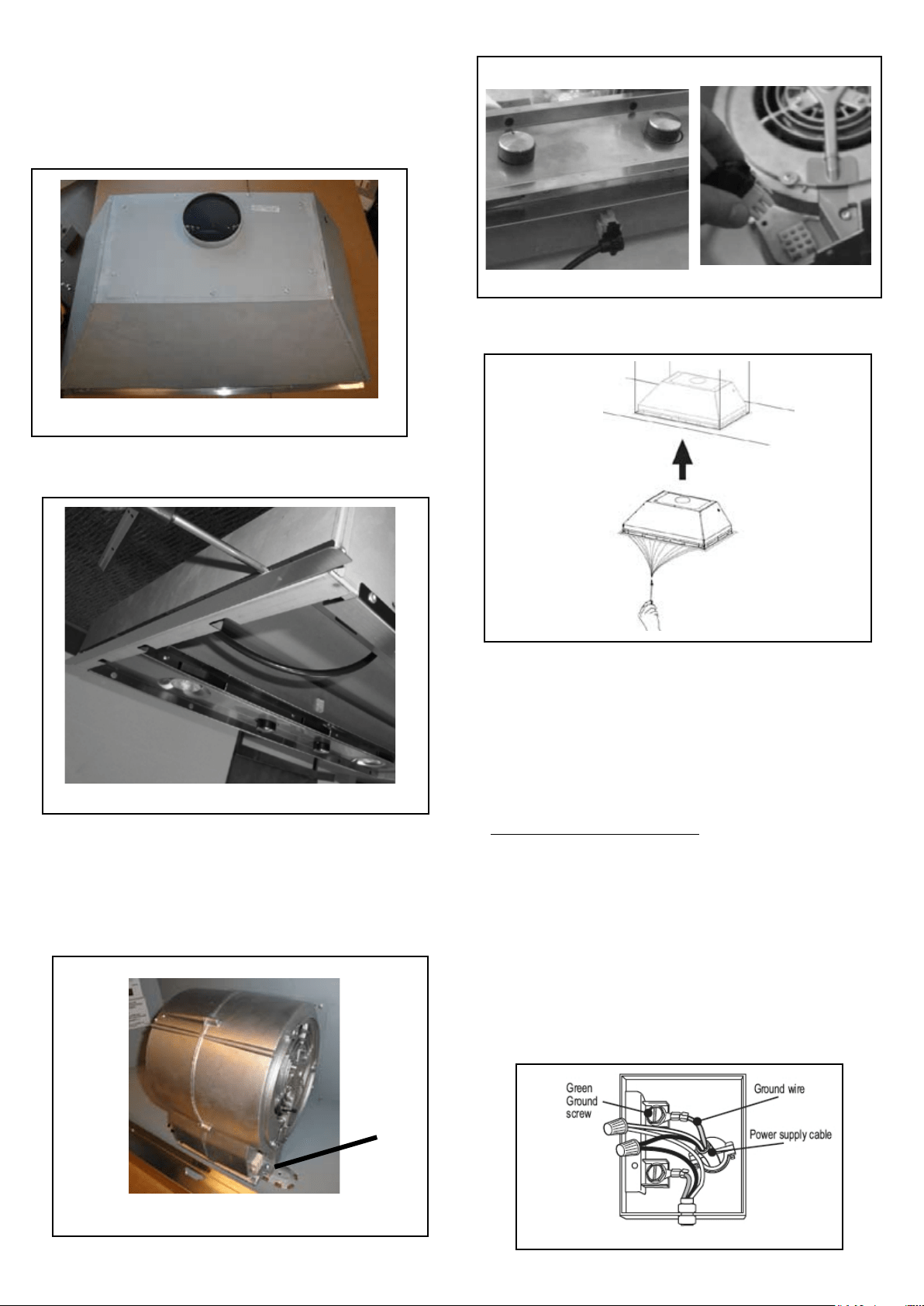
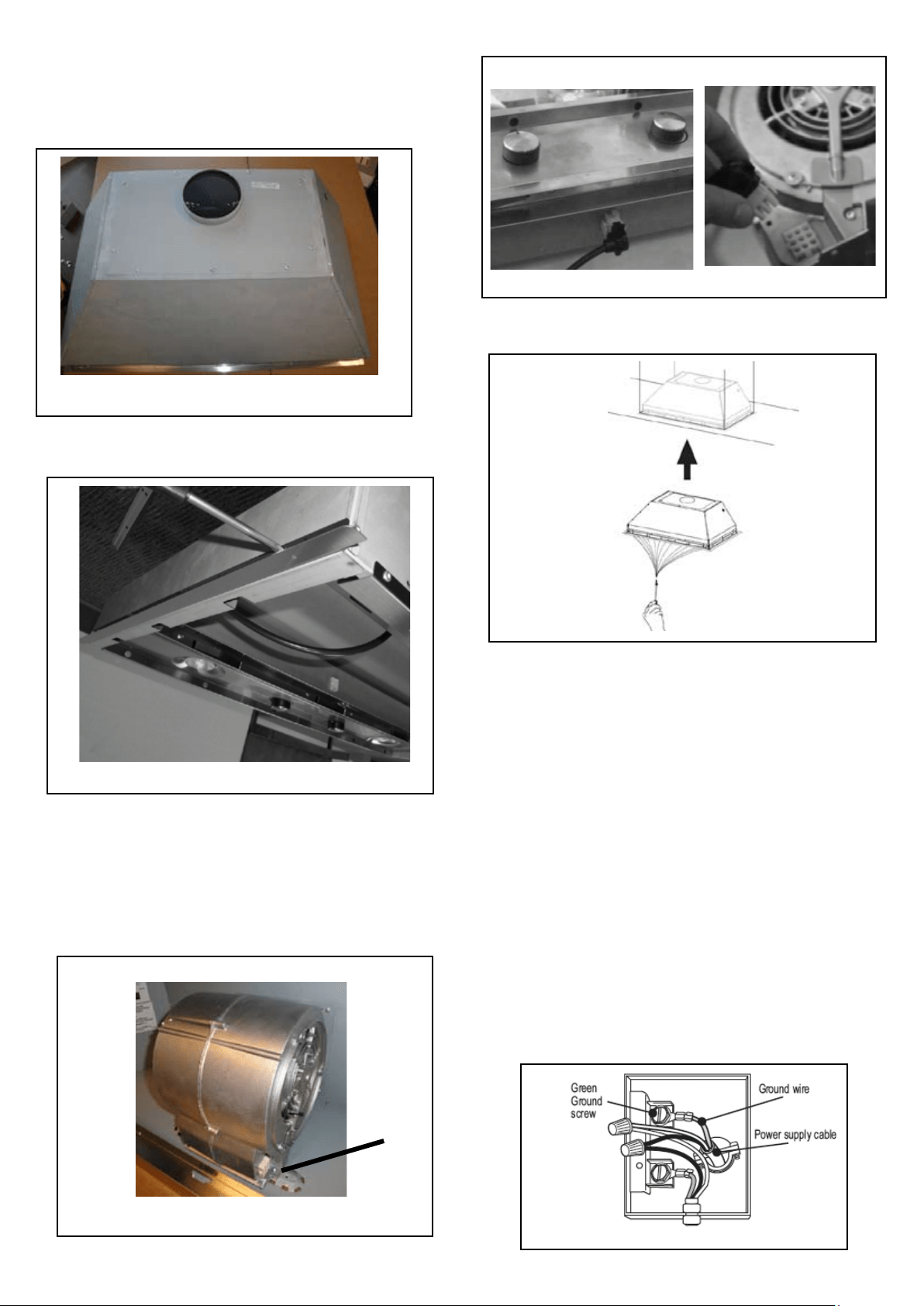
INSTALLATION WITH IB300 / IB600 INTERNAL BLOWER (300
, 600 cfm)
1. InstallthePlate B(FIGURE 8) whichcame withtheinternal
blowerkit,ontopoftherangehoodwiththeholeclosertotheback
ofthehood.Use9screwssuppliedwiththeblowerkit
6. (see FIGURE 13) Removethecoverfromtheeldwiring
compartment with a phillips screwdriver. Feed the Power Supply
Cablethroughtheelectricalknockout.ConnectthePowerSupply
Cabletotherangehoodcable.AttachtheWhiteleadofthepower
supplytotheWhiteleadoftherangehoodwithatwist-ontypewire
connector. Attach the Black lead of the power supply to the Black
lead of the rangehood with a twist-on type wire connector. Attach
thePowerSupplyCablegroundingleadtothegreenscrewprovided.
Replacethecover.
7. Connect the 6" round ductwork to the damper and seal all
connectionswithducttape.Installthegreaseltersandgreaserail.
(seepage11forinstructions)
8.Turnthepowersupplyon.Turnontheblowerandlight.Ifthe
rangehooddoesnotoperate,checkthatthecircuitbreakerisnot
trippedorthehousefuseblown.Iftheunitstilldoesnotoperate,
disconnect the power supply and check that the wiring connections
have been made properly.
9. CONTINUE TO PAGE 11
FIGURE 8
2. Removethewhiteplasticcoveringand install the 4 side trim
piecestotheoutsideofthehoodusing(16)part9bscrews,see
thesidetriminstallationin(FIGURE9).
FIGURE 9
5. Attachthehoodtothecabinetusing(12)9c.screwstothe
cabinet.FIGURE12
FIGURE 12
FIGURE 10
3. Installthemotorkitintothehoodusingthe2screwssupplied
withthemotorkitintothebackofthehood.(FIGURE10)
4.Connectthewirethatcomeswiththemotorkitfromtheside
of the motor to the connection on the inside of the light panel in
thehood.The9holeendofthewireisinstalledinthemotor,the
6holeendisconnectedtothelightpanel(FIGURE11)
FIGURE 11
FIGURE 13
B
Version10/12-Page9
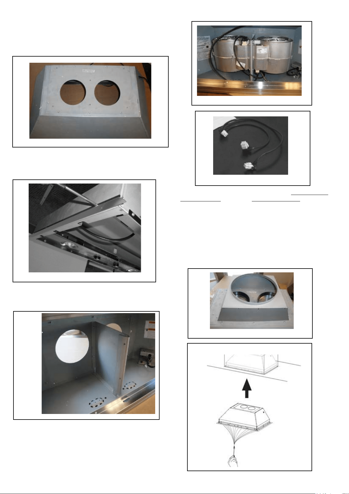
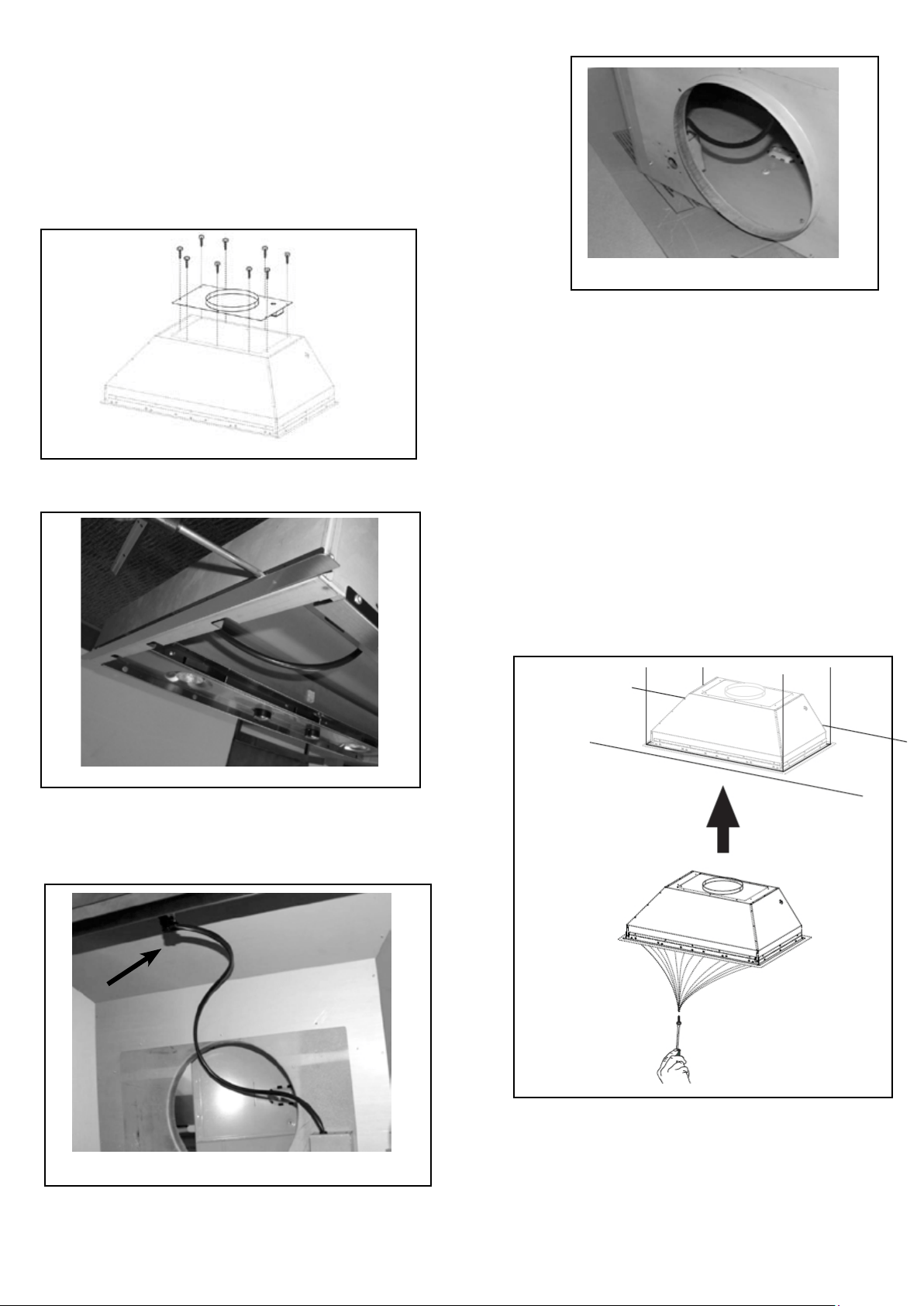
INSTALLATION WITH IB1200 INTERNAL BLOWER (1200 cfm)
1. InstallthePlateB(FIGURE14)whichcamewiththeinternal
blowerkit,ontopoftherangehoodwiththeholeslocatedcloserto
thefront.Use9screwssuppliedwiththeblowerkit
2. RemovethewhiteplasticcoveringandInstallthe4sidetrim
piecestotheoutsideofthehoodusing(16)part9bscrews,see
thesidetriminstallationin(FIGURE15).
3. Attachtheblowerbracketdividerinsidethehood,withthe2
screwsintothetopofthehoodand2screwsintotheback,all
suppliedwiththeblowerkit(FIGURE16)
FIGURE 16
FIGURE 17
4. Installthe2motorkitsintothesidesoftheblowerbracketusing
the4screwssuppliedwiththemotorkit.(FIGURE17)
5.Connectthewire(FIGURE18)thatcomeswiththemotorkit
from the side of the two motors to the connection on the inside
ofthelightpanelinthehood.Thetwo-9holeendsofthewire
areinstalledinthetwomotors,the6holeendisconnectedto
thelightpanel(FIGURE11onthepreviouspage)
FIGURE 15
FIGURE 18
FIGURE 19
6. Installthe2dampersontopofthehoodandConnect the 6"
round ductwork. Ifyouwant(1) 10" round duct to come out
ofthetopofthehood,usethetransitionpiece(FIGURE19)that
comeswiththemotorkitandinstallwithfourscrews.Ifyouwant
touse2seperate6"roundducts,donotusethetransition.
7. Attachthehoodtothecabinetusing(12)9c.screwstothe
cabinet.FIGURE20
8.Followsteps6-9onthepreviouspagetoconnectducting,
wiring,andtesttheelectricalconnection.
FIGURE 14
FIGURE 20
B
Version 10/12 - Page 10
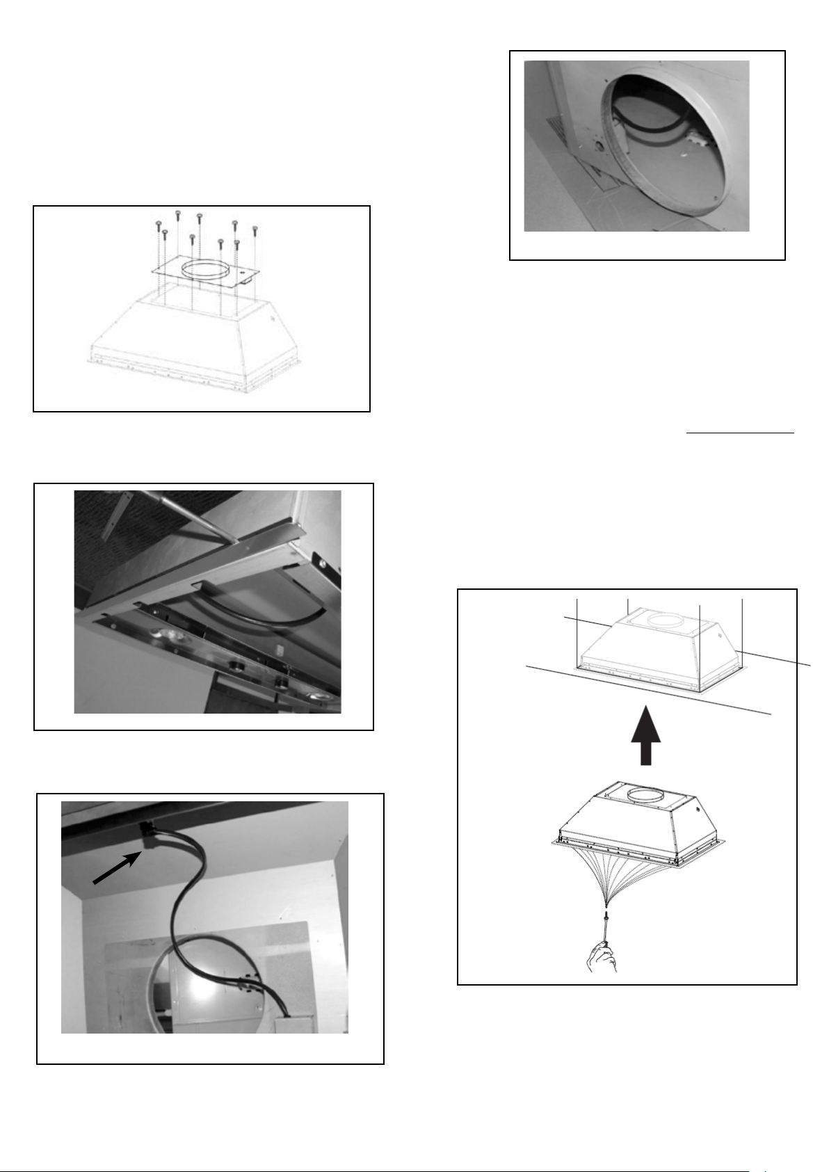
INSTALLATION WITH REMOTE BLOWER (RB900 / RB1200)
OR IN-LINE BLOWER (INLBKIT)
NOTE: FOLLOW THE INSTRUCTIONS INCLUDED WITH THE
REMOTE BLOWER TO INSTALL THE BLOWER ON THE
OUTSIDE OF YOUR HOME
.
1. InstallthePlateB(FIGURE21)whichcamewiththeremote
blowerkit,ontopoftherangehood.Use9screwssuppliedwith
theblowerkit.Removetheelectricalknockoutholeontopofthe
plate.
2. RemovethewhiteplasticcoveringandInstallthe4sidetrim
piecestotheoutsideofthehoodusing(16)part9bscrews,see
thesidetriminstallationin(FIGURE22).
FIGURE 23
FIGURE 24
4. Feed the remote blower cable thru the knockout hole in step 1
(FIGURE24).Connectthepowersupplycablefromtheremote
blowertothewiringboxonthetopductingplateofthehood.Use
step6onpage8andthediagramonpage8(FIGURE13)
5. Attachthehoodtothecabinetusing(12)9c.screwstothe
cabinet.FIGURE25
6.Followsteps6-9onpage8toconnect10" round ducting,
wiring,andtesttheelectricalconnection.Usethewiringbox
connected to the inside wall of the hood which connects to the
home power supply thru the knockout on the side of the hood.
FIGURE 21
FIGURE 22
3. Connectthewirecomingoutofthewiringboxonthetopduct
platetothelightpanel6holeslotconnectoronthefrontinside
ofthehood(FIGURE23)
FIGURE 25
B
Version 10/12 - Page 11
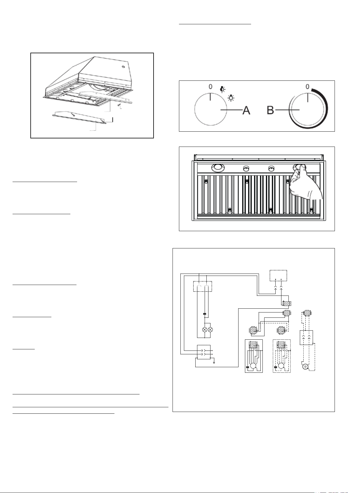
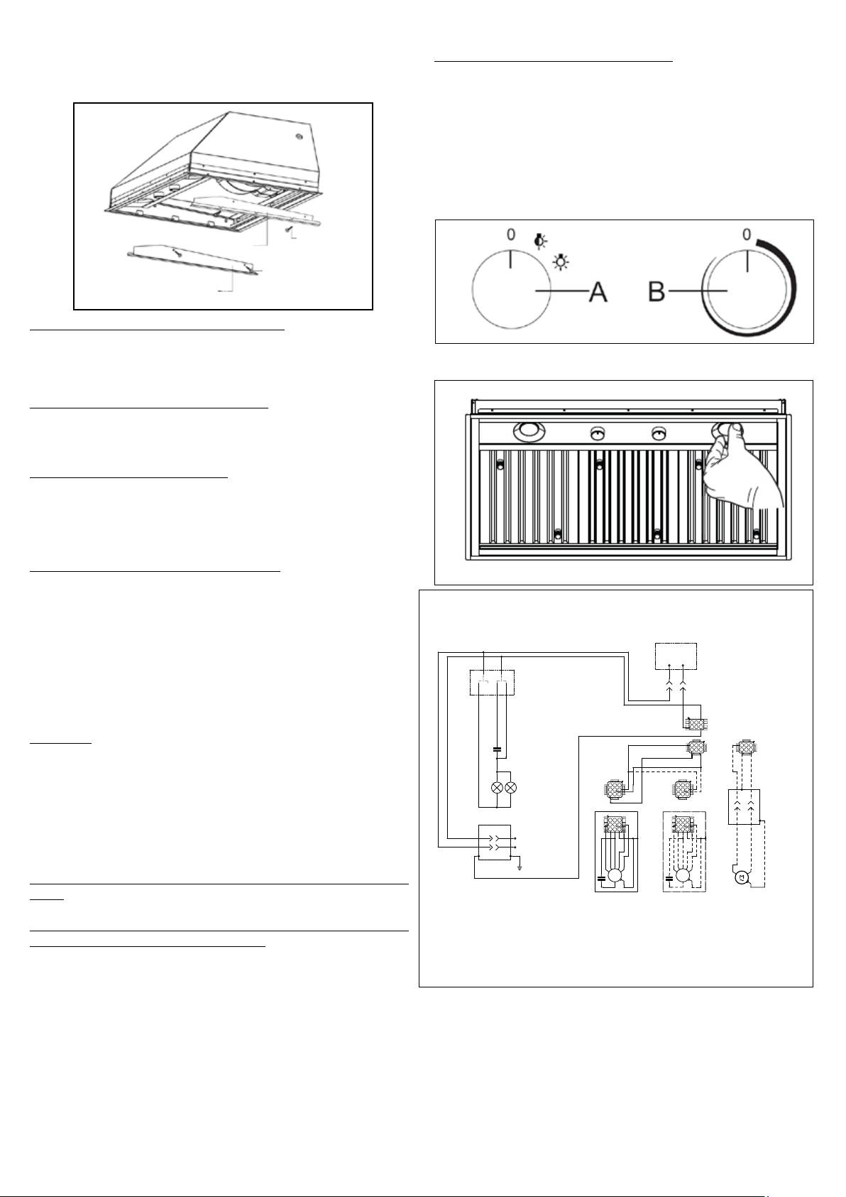
Light On/Off Button (A)
On/Offswitchforthehalogenlights.Position"0"turnsthelightsoff,
turningtheswitchtotherightoneclickisthedimmerposition,and
thenextclicktotherightisfullpower
Blower On/Off Button (B)
On/Offswitchfortheblower.Movethedialtotherighttoturnthe
blowerONandvarythespeedoftheblower.Turntotheleftat"0"
to turn it OFF.
For Best Result
Starttherangehoodseveralminutesbeforecookingtodevelopproper
airow.Allowtheunittooperateforseveralminutesaftercookingis
complete to clear all smoke and odors from the kitchen.
Cleaning
Thestainlesssteelgreaseltersandgreaserailshouldbecleaned
frequentlyin hotdetergentsolution orwashedin thedishwasher.
Cleanexteriorsurfaceswithacommerciallyavailablestainlesssteel
cleaner. Abrasives and scouring agents can scratch stainless steel
nishesandshouldnotbeusedtocleannishedsurfaces.
Grease rail and Grease Filter Installation / Removal
Remove the plastic from the lter, the knobs need to be installed
onto the lter with 2 screws to each lter
Installthegreaserailintothebackofthehood,intotheslotsonthe
insideooroftherearofthehood.TheGreaseltersshouldbe
installedbeforeoperatingtherangehood.Toinstallthelters,usethe
twoknobs(inFIGURE28)toholdthelterandinsertthelterinto
the front edge of the hood with the knobs facing out into the spring
loadedslot.Installtheotherendofthelterabovethegreaserailin
the back of the hood.
USE AND CARE INFORMATION
Thisrangehoodsystemisdesignedtoremovesmoke,cookingvapors
and odors from the cooktop area.
Rangehood Control Panel
Thecontrolpanelislocatedinthecenterofthehoodbottom.The
position and function of each control button are indicated in FIGURE
27
FIGURE 28
Replacing the Halogen Lamp
Beforeyoubegin,makesurethattherangehoodisturnedoffand
thattheotherlampshavehadsufcienttimetocool.Halogenlamps
burnextremelyhotandseriousinjurycouldresultfromtouchingahot
lamp.Pressandtwistthelamptoremove.Thenremovethelamp
and replace with a new lamp.
WIRING DIAGRAM
This rangehood uses 45 watt PAR16
Halogen Lamps.
FIGURE 27
FIGURE 26
ALL INSTALLATIONS
1. Use a drill to install side rails on the inside rangehood walls to
linetheinsidehoodwallwithstainless,2and3inFIGURE26with
9a.screws,4screwstotal.
0 1 2 3 4 5 6 7 8 9
Creato da.
Rev :
Ver :
DOLCE CORRADO
3
Materiali: non deveno contenere Pb, Cr6+, Hg, PBB, pbde, ai sensi della direttiva 2002/95 CE
SCHEMA ELETTRICO INCA PRO PLUS UL
Disposizione di messa a terra
Non rilevare quote dal grafico non apportare mod ifiche senza l'autorizzazione d'ufficio progettazione
a termini di legge ci riserviamo la proprieta' del pr esente disegno con divieto di riproduzione totale o parziale
Code :
Disegno N :
Data:
11.Nov.2010
436005092
H90_059
BLK
WHT
R11B41
LIGHT CONTROL
OFF / HALF LIGHT / ON
1
Y-G
A
RED
WIRING BOX
WHT
BLK
BLK
2 3
B
ORG
WHT
4
VLT
N
L
Y-G
LINE IN
120Vac
60Hz ~
Y-G
BLU
123
6 5 4
789
1 2 3
654
987
RED
M8 4V
120V ~
WHT
BRW
BLU
BLK
ORG
BLU
BLK
Y-G
Y-G
ON/OFF MOTOR
SPEED CONTROL
BLKBLK
BLU
123
6 5 4
789
1 2 3
654
987
RED
M8 4V
120V ~
BLU
Y-G
WHT
BRW
BLKBLK
BLU
1 2 3
654
123
6 5 4
BLK
ORG
Y-G
BLU
WHT
BLK
Y-G
WIRING BOX FOR
REMOTE BLOWER
WHT
REMOTE
BLOWER
123
6 5 4
WHT
Y-G
BLKBLK
Y-G
9a
2
3
9a
9a

Version 10/12 - Page 12
FABER WARRANTY & SERVICE (SAVE FOR YOUR RECORDS)
All Faber products are warranteed against any defect in materials or workmanship for the
originalpurchaserforaperiodof1yearfromthedateoforiginalpurchase.Thiswarranty
coverslaborandreplacementparts.Toobtainwarrantyservice,contactthedealerfrom
whomyoupurchasedtherangehood,orthelocalFaberdistributor.Ifyoucannotidentify
alocalFaberdistributor,contactusat(508)358-5353forthenameofadistributorinyour
area.
The Following is not covered by Faber's warranty:
1.Servicecallstocorrecttheinstallationofyourrangehood,toinstructyouhowtouseyour
rangehood,toreplaceorrepairhousefusesortocorrecthousewiringorplumbing.
2.Servicecallstorepairorreplacerangehoodlightbulbs,fusesorlters.Those
consumablepartsareexcludedfromwarrantycoverage.
3.Repairswhenyourrangehoodisusedforotherthannormal,single-family
household use.
4.Damageresultingfromaccident,alteration,misuse,abuse,re,ood,actsofGod,
improperinstallation,installationnotinaccordancewithelectricalorplumbingcodes,or
use of products not approved by Faber.
5.ReplacementpartsorrepairlaborcostsforunitsoperatedoutsidetheUnitedStatesor
Canada,includinganynon-ULorC-ULapprovedFaberrangehoods.
6.Repairstothehoodresultingfromunauthorizedmodicationsmadetothe
rangehood.
7.Expensesfortravelandtransportationforproductserviceinremotelocationsandpickup
and delivery charges. Faber range hoods should be serviced in the home.
Record Your Information Below:
Serial #: __________________________
Date of Purchase: ______________
Version 10/12 - Page 13
OUTILS NÉCESSAIRES À L’INSTALLATION
•Sciesauteuseouàdécouper
•Perceuse
•Mècheàbois11/4po
•Pinces
•TournevisPhillips
(Tête magnétique)
•Dénudeloucouteautoutusage
•Pincecoupanteàlmétallique
•Rubanàmesurerourègle
•Niveau
•Crayon
•Outilàcalfeutrage
•Rubanàconduit
PIÈCES FOURNIES POUR L’INSTALLATION
•1registreàclapet
•1nécessairededocumentation
PIÈCES NÉCESSAIRES POUR L’INSTALLATION
•2connecteursdeconduit
•Câbled’alimentation
•1capuchondemuroudetoit
•Conduitenmétal
•Vispoutréinforcement
•Vispourcompartimentdelage
RANGEHOOD COMPONENTS
FIGURE 1
FAISANT LE COFFRET COUPÉ
FIGURE 2
Cecapotpeutêtreinstallédirectementsuruncoffretsansrevêtementutilisant12du9cvisse(leSCHÉMA
1).Lerevêtementestconstruitdanslecapotdéjà.1.Coupezl'ouvertureaufondducoffretselonle
diagrammeci-dessous(leSCHÉMA2,3)
Dimension
extérieure
de hotte Modèle # X Y
FIGURE 3
9a
9b
9c
9d
6
7
8
9c
9b
5
4
5
4
2
1
1. Corps de capot avec les lumières et
commandes
2. le rail d'aile gauche
3. Rail de côté droit
4. (2) équilibre avant/arrière
5. (2) équilibre laissé/bon
6. ltres de graisse (3 - 36/42" / 4 - 48")
7. boutons de ltre (6 - 36,42" / 8 - 48")
8. rail de graisse
9a. (4) vis de rail latéral
9b. (16) vis d'équilibre
9c. (12) installez les vis
9d. (6 - 36,42", 8 - 48") ltrez les vis de bouton
9a
3
36"x19"INPL3619SS343/4"193/4"
36"x22"INPL3622SS343/4"223/4"
42"x19"INPL4219SS403/4"193/4"
48"x19"INPL4819SS463/4"193/4"
48"x22"INPL4822SS463/4"223/4"
Version 10/12 - Page 14
INSTALLATION
COMBINAISONS CAPOT ET KITS DE MOTEUR
CHOISISSEZ UN VENTILATEUR POUR VOTRE CAPOT
Après le choix de la largeur et de la profondeur de capot pour vos
besoins à cuire, choisissez après le type de ventilateur approprié
pour votre cuisson.
NOTE : aucun autre ventilateur
n'est compatible avec ce capot, excepté les kits
ci-dessous.
# IB600 - Kit interne de ventilateur 600 cfm
# IB1200 - Kit interne de ventilateur 1200 cfm
# RB900 - Kit à distance de ventilateur 900 cfm
# RB1200 - Kit à distance de ventilateur 1200 cfm
# INLBKIT - Dans la ligne kit de ventilateur (fournissez pour
posséder le ventilateur intégré)
ACCESSOIRES FACULTATIFS DISPONIBLES
• *Charcoal Filter
*ilestfortement-recommandéquelemodèleprofessionnelfaisant
cuiretoujourssoitexhaléàl'extérieur;pourrecyclerdesinstallations
seulement,delacanalisationestexigéepourépuiserl'unitéhorsdu
coffret.Remplacezcommenécessaireparlemêmemodèle
part # FILTER1
•
CFM Reducer part # CFMRED - Ramène le cfm à en-dessous du
cfm 300 en convertissant le conduit rond de 6 pouces en 5 pouces de
rond.
NOTE : Le kit de ltre de charbon de bois et kit de
réducteur de CFM servent avec le kit interne de
ventilateur de 600 cfm seulement
ATTENTION - pour réduire le risque du feu et de décharge électrique, installez ce rangehood seulement avec : Le fabricant à
distance de ventilateur par Faber modèle RB900 et RB1200 ou ventilateur intégral construits par les modèles IB300 ou IB600 ou
IB1200 de Faber ou avec INLBKIT et 4.2 A maximum évalué par ventilateur intégré générique appropriés pour l'usage avec la
commande de vitesse variable à semi-conducteur
INLBKIT
Version 10/12 - Page 15
PLAN DU CONDUIT
Pourassurerqueleventilateurmarchelemieux,
leconduitdoitêtreaussicourtetaussidroitque
possible.
Le ductrun ne devrait pas dépasser 50 pieds
équivalentssicanaliséutilisantleminimumexigé
de 6" ; conduit rond. Pour 10";lacanalisation
ronde avec le moteur 1200 de cfm ou le ventilateur
internede900/1200extérieurs,emploient75pieds
équivalents.Calculezlalongueurdelacanalisation
enajoutantlespiedséquivalentssurleSCHÉMA5
pourchaquemorceaudeconduitdanslesystème
qu'unexempleestdonnésurleSCHÉMA6.
Pour de meilleurs résultats, ne pas utiliser plus
de trois coudes de 90
˚
. S’assurer qu’il y ait un
minimum de 24 po de conduit droit entre les
coudes si l’on utilise plus d’un coude. Ne pas
installer deux coudes ensemble.
9FeetStraightDuct
2-90˚Elbows
WallCap
TotalSystem
9.0feet
10.0 feet
0.0 feet
19.0feet
3.0 feet
5.0 feet
12.0 feet
0.0 feet
45˚Elbow
90˚Elbow
90˚FlatElbow
WallCap
INSTALLATION POUR RECIRCULATION D'AIR
UnnécessairedesdeuxFiltres au Charbon (FIGURE 4A) estrequispourcetyped'installation.Installationpourrecirculatond'airrequis
conduitpourdivertirl'airàl'extérieurdel'armoire.Nelaconduitterminezpasdanl'armoire.
FIGURE 4 - INSTALLATION POUR RECIRCULATION D'AIR
le plafond
le plafond
inca pro 30
FIGURE 4A
conduit
hotte
encastrable
hotte
encastrable
conduit
inca pro 30
FIGURE 2
FIGURE 3
FAITES VOS COUPES-CIRCUIT
1.Démontezetdéplacezlagammelibredel'ouverturedecoffretpourfournirunaccèsplus
facileaucoffretouaucapotsupérieurdecoutume.Mettezunrevêtementdeprotection
épaisetau-dessusdecooktop,placer-danslagammeoulapartiesupérieureducomptoir
pour se protéger contre les dommages ou la saleté.
2.Déterminezetfaitestoutlenécessairecoupededanslemuret/ouleplafondpourla
canalisation.Installezlacanalisationavantlerangehood.
3.Déterminezl'endroitappropriépourlecâbled'alimentationd'énergie.Employezun11/4"
;Peudeforetpourfairecetrou.Installezlecâble.Employezlecalfeutragepoursceller
autourdutrou.Nerétablissezpaslecourantjusqu'àcequel'installationsoitcomplète.
4.Choisissezlecoupdehorstrouentpourenleverpourinstallerlecableélectrique.Utilisez
untournevispour secasseroutre ducoupcouvrant dehors.(leSCHÉMA7montreà
l'intérieurdelaboîteetdel'extérieurdecâblage)
FIGURE 7
POUR TOUTES LES INSTALLATIONS ENLEVEZ TOUT LE REVÊTEMENT DE
PROTECTION EN PLASTIQUE BLANC DU CAPOT, DES RAILS LATÉRAUX, DE
L'ÉQUILIBRE, DES RAILS DE GRAISSE ET DES FILTRES DE GRAISSE
Version10/12-Page16
INSTALLATION AVEC LE VENTILATEUR IB600 INTERNE (cfm 600)
1.InstallezleplatB(leSCHÉMA8)quiestvenuaveclekitinterne
deventilateur,surlerangehood.Utilisez9visfourniesaveclekit
de ventilateur
6. (voirleSCHÉMA13)enleverlacouvertureducompartimentde
câblage de champ avec untournevis Phillips.Alimentez le câble
d'alimentationd'énergieparlecoupdegrâceélectrique.Reliezle
câble d'alimentation d'énergie au câble de rangehood. Attachez
le l blanc de l'alimentation d'énergie au l blanc du rangehood
avecatordre-surletypeconnecteurdel.Attachezlegraphitede
l'alimentation d'énergie au graphite du rangehood avec a tordre-sur
le type connecteur de l.Attachez câble d'alimentation d'énergie
câbledemasseàlavisvertefournie.Utilisantles4trousfournisvis-
sezlecompartimentdecâblagedechampdanslemuroulecoffret
commedictéparvotreendroitdecâbled'alimentationd'énergie(vis
nonfournies).Remplacezlacouverture.
7.Reliezlacanalisationàl'amortisseuretscelleztouslesraccorde-
mentsaveclabandedeconduit.Installezlesltresdegraisseetle
raildegraisse.(voirlapage11pourdesinstructions)
8.Allumezl'alimentationd'énergie.Allumezleventilateuretallumez.
Silerangehoodnefonctionnepas,vériezqueledisjoncteurn'est
pasdéclenchéoulefusibledemaisonn'estpassoufé.Sil'unité
nefonctionnetoujourspas,déconnectezl'alimentationd'énergieet
vériezquelesrapportsdecâblageontétéétabliscorrectement.
FIGURE 8
2.Installezles4morceauxlatérauxsurlecapotutilisantdesvis
(de16)parts9bdedans(leSCHÉMA9).
FIGURE 9
5. Attachezlecapotdanslecoffretutilisant(12)9c.visdansle
coffret.LeSCHÉMA12
FIGURE 12
FIGURE 10
3.Installezlekitdemoteursurlecapotutilisantles2visfournies
aveclekitdemoteurdansledosducapot.(LeSCHÉMA10)
4.Reliezlelquivientaveclekitdemoteurducôtédumoteur
au raccordement sur l'intérieur du panneau léger dans le capot.
L'extrémitéde9trousdulestinstalléedanslemoteur,l'extrémité
de6trousestreliéeaupanneauléger(leSCHÉMA11)
FIGURE 11
FIGURE 13
B

Version10/12-Page17
INSTALLATION AVEC LE VENTILATEUR IB1200 INTERNE (cfm 1200)
1. InstallezleplatB(leSCHÉMA14)quiestvenuaveclekitinterne
deventilateur,surlerangehood.Utilisez9visfourniesaveclekitde
ventilateur
2.Installezles4morceauxlatérauxsurlecapotutilisantdesvis
(de16)parts9bdedans(leSCHÉMA15).
3. Attachezàl'intérieurducapotlaparenthèsedeventilateur,
avecles2visdansledessusducapot,l'aveztoutfourniavecle
kitdeventilateur(leSCHÉMA16)
FIGURE 16
FIGURE 17
4.Installezles2kitsdemoteursurlescôtésdelaparenthèse
de ventilateur utilisant les 4 vis fournies avec le kit de moteur.
(LeSCHÉMA17)
5.Reliezlel(leSCHÉMA18)quivientaveclekitdemoteurdu
côtédesdeuxmoteursauraccordementsurl'intérieurdupanneau
légerdanslecapot.L'extrémitéde9trousdulestinstalléedans
lemoteur,l'extrémitéde6trousestreliéeaupanneauléger(le
SCHÉMA11surlapageprécédente)
FIGURE 15
FIGURE 18
FIGURE 19
6.Installezles2amortisseurssurlecapot.Sivousvoulezun
10";leconduitrondpoursortirdudessusducapot,emploient
lemorceaudetransition(leSCHÉMA19)quivientaveclekitde
moteuretl'installentavecquatrevis.Sivousvoulezemployer2
6"séparés;lesconduitsronds,n'emploientpaslatransition.
7.Attachezlecapotdanslecoffretutilisant(12)9c.visdansle
coffret.LeSCHÉMA20
8.Suivezlesétapes6-8àlapageprécédentepourrelierla
canalisation,câblage,etexaminezleraccordementélectrique.
FIGURE 14
FIGURE 20
B
Version 10/12 - Page 18
INSTALLATION AVEC LE VENTILATEUR À DISTANCE (RB900
/ RB1200 OU VENTILATEUR INTÉGRÉ (INLBKIT)
NOTE : SUIVEZ LES INSTRUCTIONS INCLUSES AVEC LE
VENTILATEUR À DISTANCE POUR INSTALLER LE
VENTILATEUR SUR L'EXTÉRIEUR DE VOTRE MAISON.
1.InstallezleplatB(leSCHÉMA21)quiestvenuaveclekità
distancedeventilateur,surlerangehood.Utilisez9visfournies
aveclekitdeventilateur.Enlevezletrouélectriquedecoupde
grâcesurleplat.
2.Installezles4morceauxlatérauxsurlecapotutilisantdesvis
(de16)parts9bdedans(leSCHÉMA22).
FIGURE 23
FIGURE 24
4.Alimentezlecâbleàdistancedeventilateurparletroude
coupdegrâcedansl'étape1(leSCHÉMA24).Reliezlecâble
d'alimentationd'énergieduventilateuràdistancedanslaboîte
decâblageduplatsupérieurdecanalisationducapot.Employez
l'étape6àlapage8etlediagrammeàlapage8(leSCHÉMA
13)
5. Attachezlecapotdanslecoffretutilisant(12)9c.visdansle
coffret.LeSCHÉMA25
6.Suivezlesétapes6-8àlapage16pourrelierlacanalisa-
tion,câblage,etexaminezleraccordementélectrique.Utilisez
laboîtedecâblagereliéeaumurintérieurducapotquiserelie
àl'alimentationd'énergieàlamaisonparlecoupdegrâcedu
côtéducapot.
FIGURE 21
FIGURE 22
3. Reliezlelsortantdelaboîtedecâblageduplatsupérieurde
conduitauconnecteurlégerdefentedetroudupanneau6sur
l'avantàl'intérieurdeducapot(leSCHÉMA23)
FIGURE 25
B
Version10/12-Page19
Bouton "Marche/Arrêt" léger (A)
Commutateur"Marche/Arrêt"pourleslumièresd'halogène.Placez
le";0";arrêteleslumières,larotationducommutateuraubonun
clicestlapositionplusfaible,etleprochainclicversladroiteestde
toute puissance
Bouton "Marche/Arrêt" de ventilateur (B)
Commutateur"Marche/Arrêt"pourleventilateur.Déplacezlecad-
ran vers la droite d'allumer le ventilateur et de varier la vitesse du
ventilateur.Tournez-vousverslagaucheau";0";pourl'arrêter.
Pour le meilleur résultat Commencez le rangehood plusieurs
minutes avant la cuisson pour développer le ux d'air approprié.
Permettez à l'unité de fonctionner pendant plusieurs minutes
après cuisson est complet pour dégager toutes les fumée et
odeurs de la cuisine.
Nettoyage
Lesltresdegraissed'acierinoxydableetleraildegraissedevraient
être nettoyés fréquemment dansla solution détersive chaudeou
êtrelavésdanslelave-vaisselle.Nettoyezlessurfacesextérieures
avecundécapantdisponibledanslecommerced'acierinoxydable.
Lesabrasifsetlesagentsderécuragepeuventrayerdesnitions
d'acierinoxydableetnedevraientpasêtreemployéspournettoyer
lessurfacesdenition.
Graissez l'installation de ltre de rail et de graisse/déplace-
ment
Éliminez le plastique du ltre, les boutons doivent être installés
sur le ltre avec 2 vis sur chaque ltre
Installezleraildegraissesurledosducapot,surlesfentessurle
plancherintérieurdel'arrièreducapot.Lesltresdegraissedevraient
êtreinstalléavantd'actionnerlerangehood.Pourinstallerlesltres,
employezlesdeuxboutons(surleSCHÉMA28)pourtenirleltre
etpourinsérerleltredanslebordavantducapotaveclesboutons
faisantfacedehorsdanslafenteàressort.Installezl'autreextrémité
dultreau-dessusduraildegraissedansledosducapot.
L'INFORMATION DE SOIN D'UTILISER-ET
Cesystèmederangehoodestconçupourenleverlafumée,faisant
cuire des vapeurs et des odeurs du secteur de cooktop.
Panneau de commande de Rangehood
Lepanneaudecommandeestplacaucentredufonddecapot.La
positionetlafonctiondechaqueboutondecommandesontindiquées
surleSCHÉMA27
FIGURE 28
Remplacement de la lampe d'halogène
Avantquevouscommenciez,assurez-vousquelerangehoodest
arrêtéetquelesautreslampesonteuletempssufsantpourse
refroidir.Leslampesd'halogènebrûlentextrêmementchaudetles
dommagessérieuxpourraientrésulterdetoucherunelampechaude.
Pressezettordezlalampepourenlever.Alorsenlevezlalampeet
laremplacezparunenouvellelampe.
WIRING DIAGRAM
Ce rangehood utilise des lampes d'halogène
de 45 watts PAR16.
FIGURE 27
FIGURE 26
TOUTES LES INSTALLATIONS
1.Installezlesrailslatéraux,2et3surleSCHÉMA26avec9a.
et9b.vis,4totaux.
0 1 2 3 4 5 6 7 8 9
Creato da.
Rev :
Ver :
DOLCE CORRADO
3
Materiali: non deveno contenere Pb, Cr6+, Hg, PBB, pbde, ai sensi della direttiva 2002/95 CE
SCHEMA ELETTRICO INCA PRO PLUS UL
Disposizione di messa a terra
Non rilevare quote dal grafico non apportare mod ifiche senza l'autorizzazione d'ufficio progettazione
a termini di legge ci riserviamo la proprieta' del pr esente disegno con divieto di riproduzione totale o parziale
Code :
Disegno N :
Data:
11.Nov.2010
436005092
H90_059
BLK
WHT
R11B41
LIGHT CONTROL
OFF / HALF LIGHT / ON
1
Y-G
A
RED
WIRING BOX
WHT
BLK
BLK
2 3
B
ORG
WHT
4
VLT
N
L
Y-G
LINE IN
120Vac
60Hz ~
Y-G
BLU
123
6 5 4
789
1 2 3
654
987
RED
M8 4V
120V ~
WHT
BRW
BLU
BLK
ORG
BLU
BLK
Y-G
Y-G
ON/OFF MOTOR
SPEED CONTROL
BLKBLK
BLU
123
6 5 4
789
1 2 3
654
987
RED
M8 4V
120V ~
BLU
Y-G
WHT
BRW
BLKBLK
BLU
1 2 3
654
123
6 5 4
BLK
ORG
Y-G
BLU
WHT
BLK
Y-G
WIRING BOX FOR
REMOTE BLOWER
WHT
REMOTE
BLOWER
123
6 5 4
WHT
Y-G
BLKBLK
Y-G
9a
9a
2
3

Version 10/12 - Page 20
FABER GARANTIE ET SERVICE (
ÉCONOMISER POUR VOS ENREGISTREMENTS
)
Fabergarantitàl’utilisateur-acheteurd’originequelesproduitsFabervendusneufsparnoussontsansvicede
matérieletdemain-d’oeuvred’originepourunepérioded’unanàpartirdeladated’achat.Lagarantiecouvre
lamain-d’oeuvreetlespiècesderemplacement.And’obtenirunservicesousgarantie,communiqueravecle
marchandoùlahotteaétéachetéeouledistributeurFaberdelarégion.Sil’onnepeuttrouverdedistributeur
Faber,communiqueravecnousau(508)358-5353and’obtenirlenomd’undistributeurdanslarégion.
Les frais suivants ne sont pas couverts par la garantie Faber :
1. Lesappelsdeservicepourcorrigerl’installationdevotrehottedecuisinière,pourvousindiquer
commentutiliservotrehottedecuisinière,pourremplacerouréparerlesfusiblesdevotremaisonou
pourcorrigervotrecâblageouvotresystèmedeplomberie.
2. Lesappelsdeservicepourremplacerouréparerlesampoules,lesfusiblesoules
ltresdevotrehottedecuisinière.
3. Lesréparationslorsquevotrehottedecuisinièreaétéutiliséeplusquelanormale,
c'est-à-direplusquepourunefamilleparfoyer.
4. Lesdommagesrésultantd’unaccident,del’altération,d’unemalutilisation,d’unacte
deDieu,d’uneinstallationinappropriée,d’uneinstallationnon-conformeaux
normesd’électricitéoudeplomberieoud’uneutilisationdel’appareilnonapprouvéeparFaber.
5. Lespiècesderemplacementoulesfraisdemaind’œuvrepourlesunités
utiliséesendehorsduCanadaoudesÉtatsUnis,incluanttouteshottedecuisinière
approuvéeparFabernonULouC-UL.
6. Lesréparationsduesàdesmodicationsnon-autoriséessurvotrehottedecuisinière.
7. Lesfraisdetransportdel’appareilpourréparationsàdistance.
Enregistrez Votre Information Ci-dessous:
Séquentiel #: __________________________
Date d'achat: ______________