Loading ...
Loading ...
Loading ...
20En
control of an external power amp or the
vehicle’s auto-antenna relay control
terminal (max. 300 mA 12 V DC). If the
vehicle is equipped with a glass antenna,
connect it to the antenna booster power
supply terminal.
• Never connect the blue/white cable to
the power terminal of an external power
amp. Also, never connect it to the power
terminal of the auto antenna. Doing so
may result in battery drain or a
malfunction.
• The graphical symbol placed on
the product means direct current.
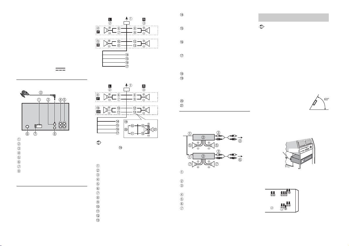
This unit
Power cord input
Microphone input
Microphone 3 m (9 ft. 10-1/8 in.)
Rear output or subwoofer output
Front output
Antenna input
Fuse (10 A)
Wired remote input
Hard-wired remote control adapter can
be connected (sold separately).
Power cord
Perform these connections when not
connecting a rear speaker lead to a
subwoofer.
Perform these connections when using a
subwoofer without the optional amplifier.
Important
In the case of above, two 4 Ω
subwoofers wired in parallel will represent
a 2 Ω load.
To power cord input
Left
Right
Front speaker
Rear speaker
White
White/black
Gray
Gray/black
Green
Green/black
Violet
Violet/black
Black (chassis ground)
Connect to a clean, paint-free metal
location.
Yel low
Connect to the constant 12 V supply
terminal.
Red
Connect to terminal controlled by the
ignition switch (12 V DC).
Blue/white
Connect to the system control terminal
of the power amp or auto-antenna relay
control terminal (max. 300 mA 12 V DC).
Subwoofer (4 Ω)
When using a subwoofer of 2 Ω, be sure
to connect the subwoofer to the violet
and violet/black leads of this unit. Do
not connect anything to the green and
green/black leads.
Not used.
Subwoofer (4 Ω) × 2
Power amp (sold separately)
Perform these connections when using the
optional amplifier.
System remote control
Connect to blue/white cable.
Power amp (sold separately)
Connect with RCA cables (sold
separately)
To front output
Front speaker
To rear output or subwoofer output
Rear speaker or subwoofer
Important
• Check all connections and systems before
final installation.
• Do not use unauthorized parts as this
may cause malfunctions.
• Consult your dealer if installation requires
drilling of holes or other modifications to
the vehicle.
• Do not install this unit where:
–it may interfere with operation of the
vehicle.
–it may cause injury to a passenger as a
result of a sudden stop.
• Install this unit away from hot places such
as near the heater outlet.
• Optimum performance is
obtained when the unit is
installed at an angle of less
than 60°.
• When installing, to ensure proper heat
dispersal when using this unit, make sure
you leave ample space behind the rear
panel and wrap any loose cables so they
are not blocking the vents.
1 Determine the appropriate position
where the holes on the bracket and
the side of the unit match.
2 Tighten the screws on each side.
Installation
Leave ample
space
5 cm
5 cm
Loading ...
Loading ...
Loading ...