www.lg.com
OWNER'S MANUAL
CLOUD MONITOR
(LED MONITOR)
19CNT42K
Please read the safety information carefully before using the product.
CLOUD Monitor(LED Monitor) Model
English

2
ENG
English
Table of Contents
TABLE OF CONTENTS
3 ASSEMBLING AND
PREPARING
3 Unpacking
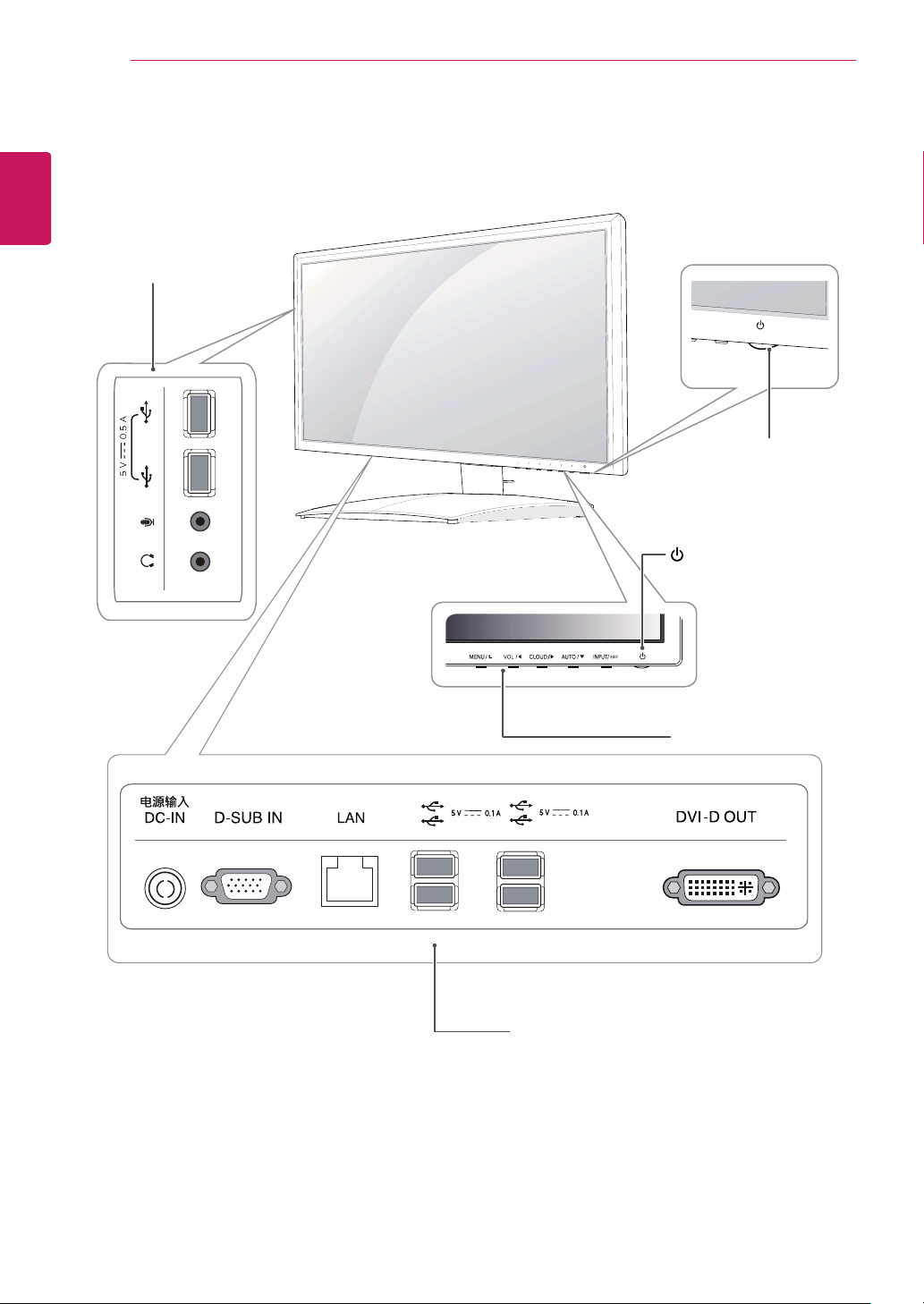
4 Parts and buttons
5 Lifting and moving the Monitor
5 Setting Up the Monitor set
5 - Attaching the Stand Base
6 - Mounting on a table
6 - Adjusting the angle
7 - Adjusting the stand height
7 - Using the Kensington locking device
8 - Detaching the stand base
8 - Detaching the stand body
9 - Swivel stand
9 - Using the Pivot function
10 - Installing the wall mount plate
10 - Mounting on a wall
12 USING THE MONITOR SET
12 Connecting Input Signal Cable
12 - D-SUB IN connection - PC
13 - DVI connection
14 Connecting LAN/Peripherals
14 - LAN connection
15 - Peripheral device connection
16 - Self Image Adjustment
17 CUSTOMIZING SETTINGS
18 Customizing Settings
18 - Menu Settings
19 - PICTURE
20 - COLOR
21 - DISPLAY
22 - OTHERS
23 - VOLUME
24 TROUBLESHOOTING
26 PRODUCT SPECIFICATION
27 Preset Mode
27 Power Indicator
28 PROPER POSTURE
28 Proper posture for using the monitor
29 USING THE CITRIX CLOUD
MONITOR
29 Initial Screen
29 Log in Screen
31 Application Screen
32 Power Button
32 Setting Button
37 Info Button
38 Pop-up Message Linked to eZ-CMS
3
ENG
English
ASSEMBLING AND PREPARING
ASSEMBLING AND PREPARING
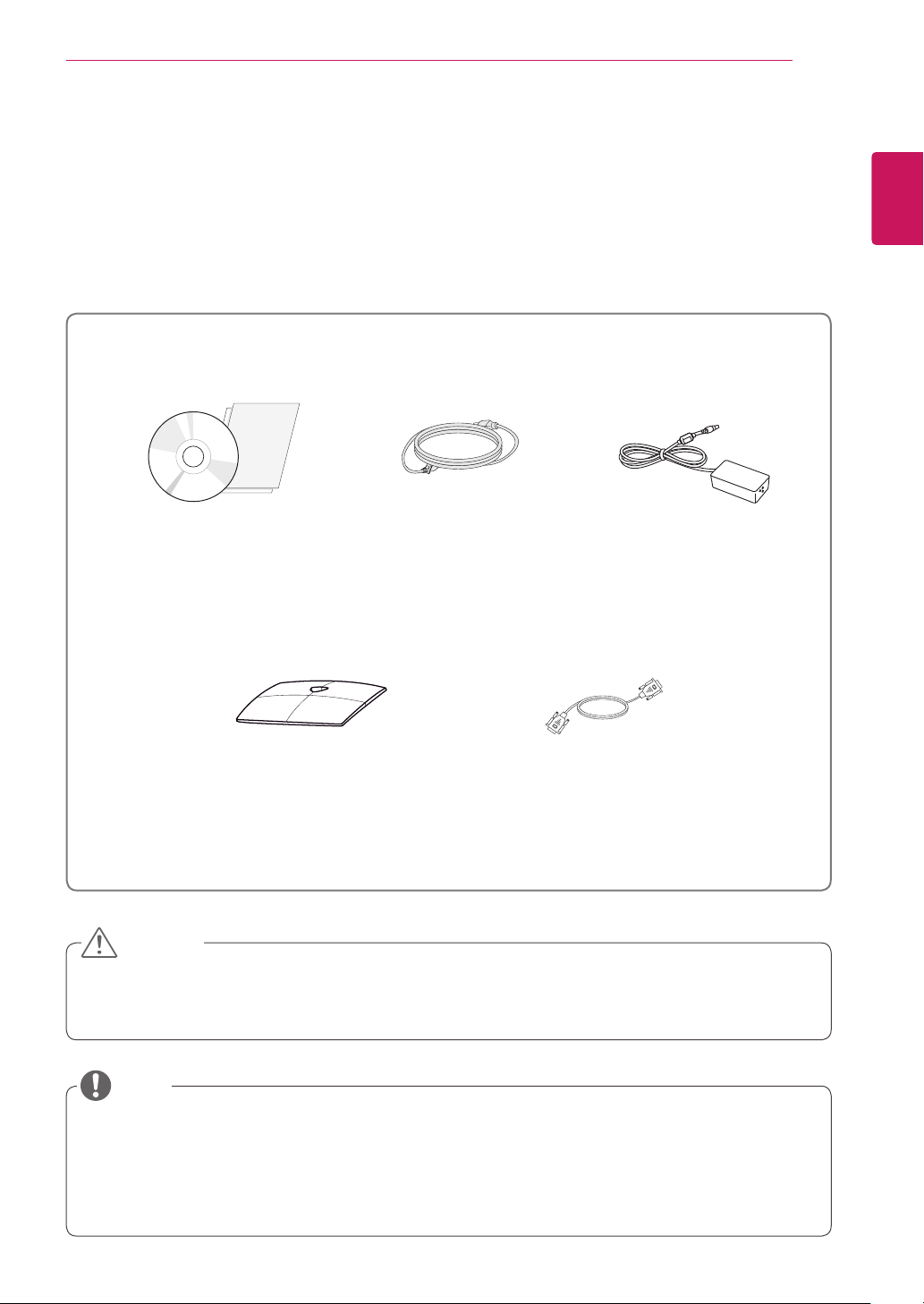
Unpacking
Please check whether all the components are included in the box before using the product. If there are
missing components, contact the retail store where you purchased the product. Note that the product and
components may look different from those shown here.
y
Only use an approved LG power adapter.
y
Damage caused by other power adapters is not covered by warranty.
y
Note that the components may look different from those shown here.
y
Without prior notice, all information and specifications in this manual are subject to change to improve
the performance of the product.
y
To purchase optional accessories, visit an electronics store or online shopping site or contact the retail
store where you purchased the product.
Power CordUser Manual/Card
Stand Base
Adaptor
CAUTION
NOTE
15-pin D-SUB Signal Cable
(This cable is not included in all
counties)

5
ENG
English
ASSEMBLING AND PREPARING
Setting Up the Monitor set
Attaching the Stand Base
1
Place the monitor's screen face down.
y
To protect the screen from scratches, cover
the surface with a soft cloth.
3
Using a coin, turn the screw clockwise to se-
cure
the
stand base.
2
Check the
position (at the front and rear)
of
the stand body,
then
mount the
stand base
on
the
stand body
as shown in the figure.
CAUTION
Stand Body
Stand Base
Stand Base
Lifting and moving the
Monitor
Please heed the following information when
moving the monitor.
y
Avoid touching the screen at all times, as this
may result in damage to the screen or pixels .
CAUTION
y
It is recommended to move the Monitor in
the box or packing material that the Monitor
originally came in.
y
Before moving or lifting the Monitor,
disconnect the power cord and all cables.
y
Hold the top and bottom of the Monitor frame
firmly. Make sure not to hold the transparent
part area.
y
When holding the Monitor, the screen should
face away from you to prevent the screen
from scratches.
y
When transporting the Monitor, do not
expose the Monitor to jolts or excessive
vibration.
y
When transporting the Monitor, keep the
Monitor upright, never turn the Monitor on its
side, or tilt towards the left or right.
6
ENG
English
ASSEMBLING AND PREPARING
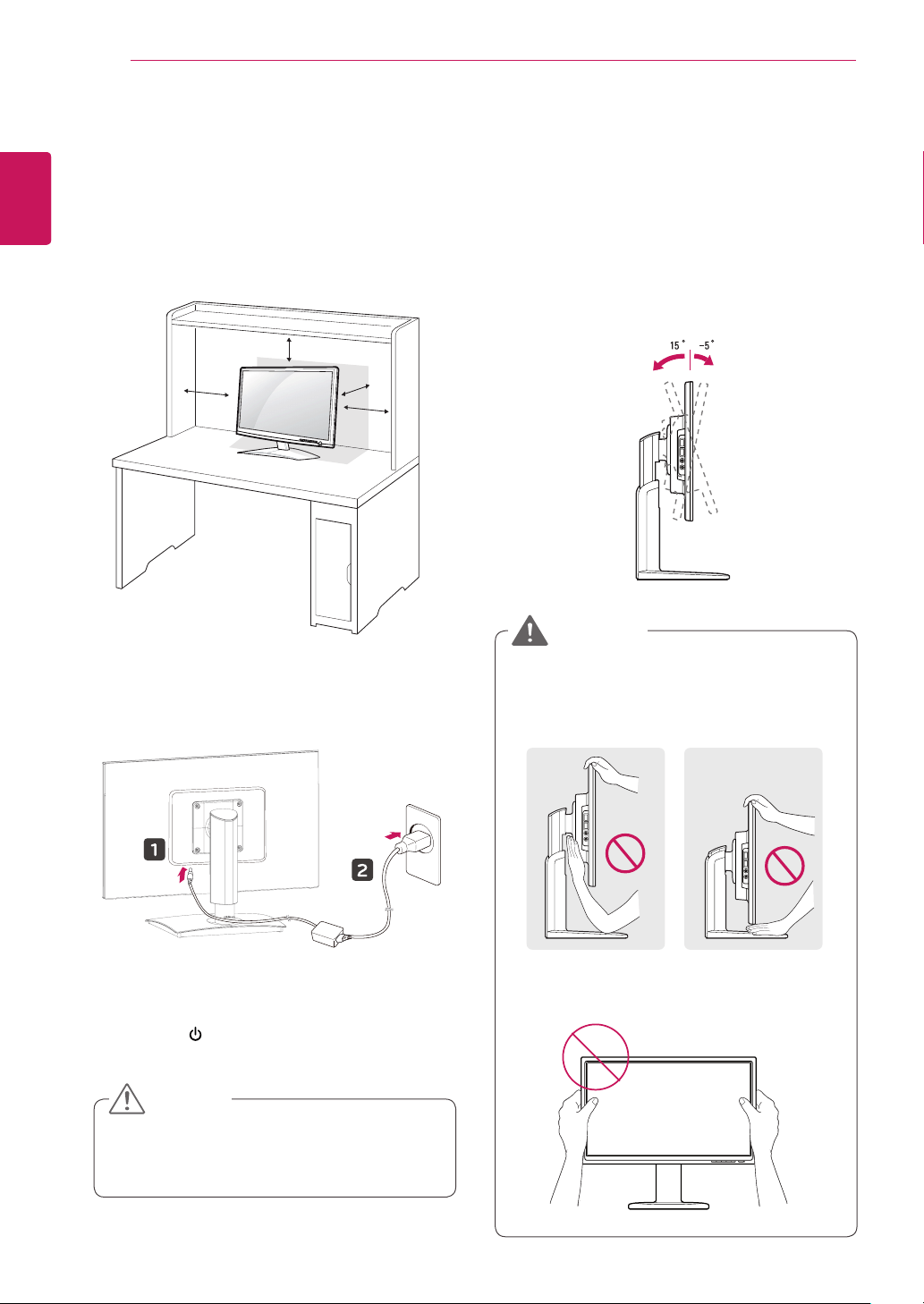
Adjusting the angle
1
Place the monitor mounted on the stand base
in an upright position.
2
Adjust the angle of the screen. The angle of
the screen can be adjusted up to 5° forwards
and 15° backwards for a comfortable viewing
experience.
y
To avoid injury to the fingers when adjusting
the screen, do not hold the lower part of the
monitor's frame as illustrated below.
y
Be careful not to touch or press the screen
area when adjusting the angle of the monitor.
WARNING
Mounting on a table
1
Lift the monitor and place it on the table in an
upright position.
Install at least
10 cm
away from the wall to
ensure sufficient ventilation.
2
Connect the adaptor to the monitor, then plug
the power cord into the wall outlet.
3
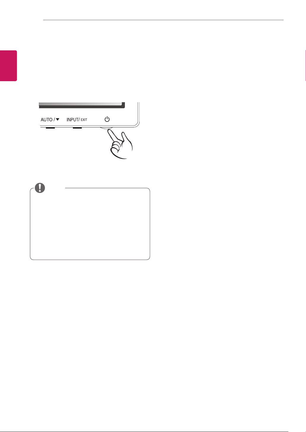
Press the (Power) button on the front of the
monitor to turn on the monitor.
10 cm
10 cm
10 cm
10 cm
y
Unplug the power cord prior to moving or
installing the monitor. There is risk of electric
shock.
CAUTION
Front SideRear Side
7
ENG
English
ASSEMBLING AND PREPARING
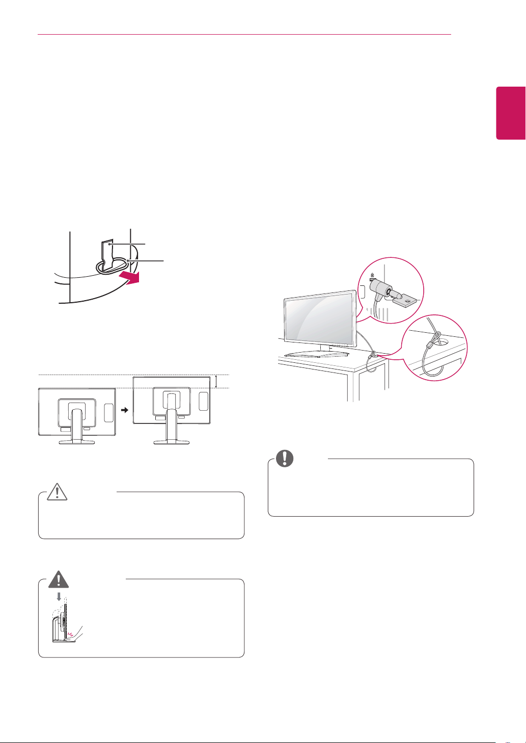
Using the Kensington locking
device
The connector for the Kensington lock is located
on the rear of the monitor.
For more information on installation and usage,
refer to the Kensington lock user manual or visit
the website at http://www.kensington.com.
Connect the monitor to the table with the Kensing-
ton lock cable.
y
Using the Kensington lock is optional. The
accessories can be purchased at your local
electronics store.
NOTE
y
Once the pin is removed, it is not necessary
to re-insert it to adjust the height.
Adjusting the stand height
1
Place the monitor mounted on the stand base
in an upright position.
2
Remove the
tape
attached at the bottom rear
of the
stand body,
then pull out the
locking
pin
.
3
The height can be adjusted up to
130 mm
.
y
Do not put your finger be-
tween the screen and the
base (chassis) when adjust-
ing the screen's height.
Tape
Locking Pin
Stand Body
CAUTION
WARNING
130.0mm
8
ENG
English
ASSEMBLING AND PREPARING
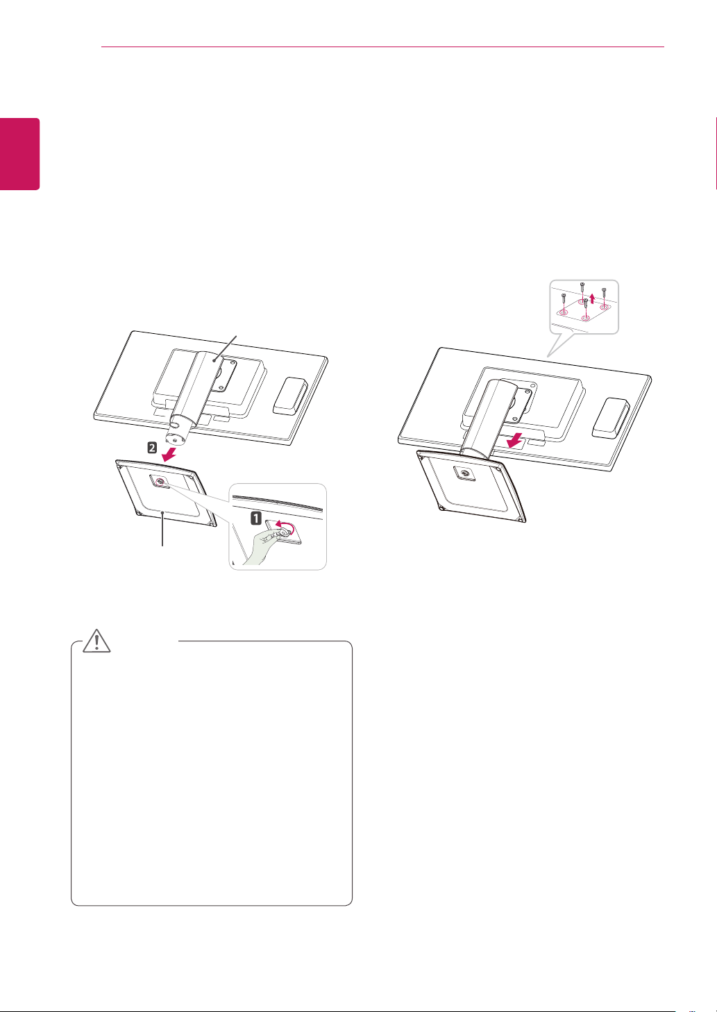
Detaching the stand body
1
Place the monitor's screen face down. To
protect the screen from scratches, cover the
surface with a soft cloth.
2
Using a screwdriver, remove the four screws
and detach the stand from the monitor.
y
The components appearing in the illustra-
tions may look different from the actual prod-
uct.
y
Do not carry the monitor upside-down as this
may cause it to fall off its stand, resulting in
damage or injury.
y
To avoid damaging the screen when lifting
or moving the monitor, only hold the stand or
the plastic cover. This avoids putting unnec-
essary pressure on the screen.
y
Only remove the tape and the locking pin
when the monitor is mounted on the stand
base and is in an upright position. Otherwise,
the stand body may protrude, which may
lead to injury.
Detaching the stand base
1
Place the monitor's screen face down.
To protect the screen from scratches, cover the
surface with a soft cloth.
2
Using a coin, turn the screw in the stand base
counterclockwise. Detach the
stand base
from
the
stand body
.
CAUTION
Stand Body
Stand Base
9
ENG
English
ASSEMBLING AND PREPARING
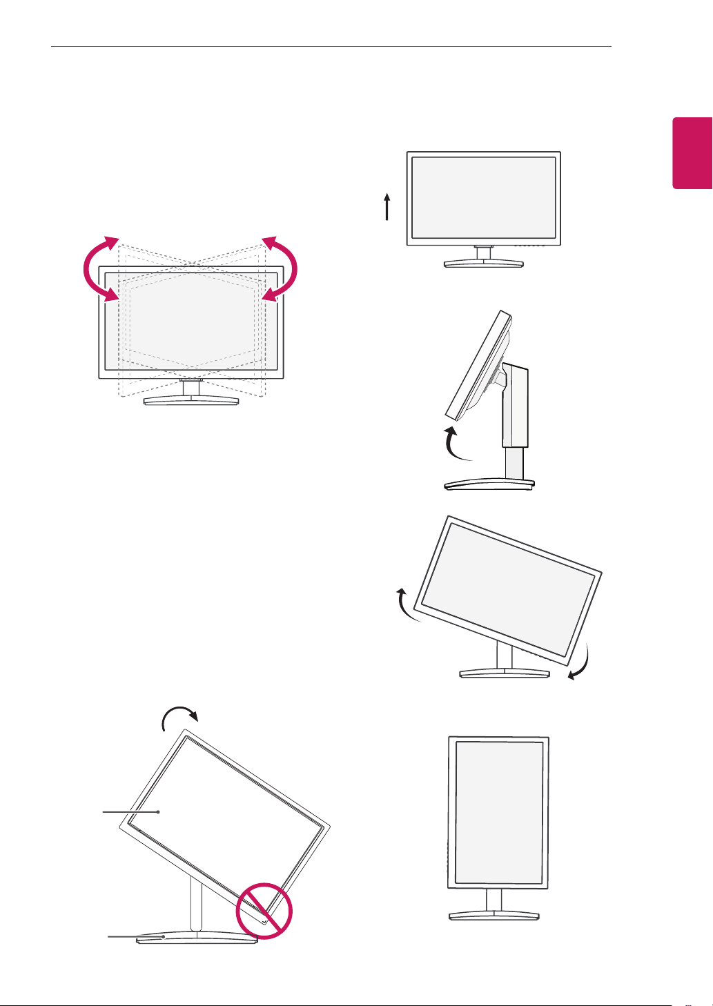
Swivel stand
y
Image shown may differ from your Monitor
set.
1
Swivel 90 degrees and adjust the angle of the
Monitor set to suit your view.
1
Lift the monitor to its highest height to utilize
the Pivot function.
Using the Pivot function
The pivot function allows you to rotate the screen
90 degrees clockwise.
2
Landscape & Portrait : You can rotate the panel
90° clockwise. Please be cautious and avoid
contact between the monitor head and the
Stand Base when rotating the screen to access
the Pivot function. If the monitor head touches
the Stand Base, then the Stand Base could
crack.
Head
section
Stand
section
3
Be careful with the cables when rotating the
screen.
10
ENG
English
ASSEMBLING AND PREPARING
10 cm
10 cm
10 cm
10 cm
If you intend to mount the Monitor set to a wall,
attach Wall mounting interface (optional parts) to
the back of the set.
When you install the Monitor set using a wall
mounting interface (optional parts), attach it
carefully so it will not drop.
1
Please, Use the screw and wall mount interface
in accordance with VESA Standards.
2
If you use screw longer than standard, the
monitor might be damaged internally.
3
If you use improper screw, the product might be
damaged and drop from mounted position. In
this case, LG Electronics is not responsible for
it.
4
VESA compatible.
5
Please use VESA standard as below.
y
784.8 mm (30.9 inch) and under
* Wall Mount Pad Thickness : 2.6 mm
* Screw : Φ 4.0 mm x Pitch 0.7 mm x
Length 10 mm
y
787.4 mm (31.0 inch) and above
* Please use VESA standard wall mount pad
and screws.
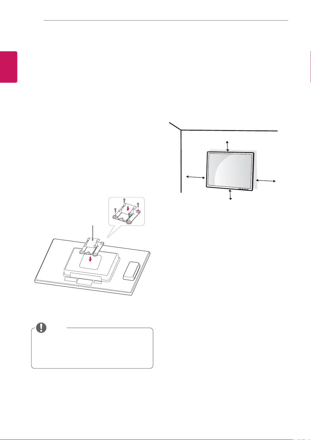
Mounting on a wall
Install the monitor at least 10 cm away from the
wall and leave about 10 cm of space at each side
of the monitor to ensure sufficient ventilation. De-
tailed installation instructions can be obtained from
your local retail store. Please refer to the manual
to install and set up a tilting wall mounting bracket.
Installing the wall mount plate
This monitor has a VESA compatible mount on the
back. Most mounts will require an LG mounting
plate.
1
Place the monitor's screen face down. To
protect the screen from scratches, cover the
surface with a soft cloth.
2
Place the wall mount plate on the monitor and
align it with the screw holes on the monitor.
3
Using a screwdriver, tighten the four screws to
fix the plate onto the monitor.
y
The wall mount plate is sold separately.
y
For more information on the installation, refer
to the wall mount plate's installation guide.
NOTE
Wall Mount Plate
11
ENG
English
ASSEMBLING AND PREPARING
y
Unplug the power cord before moving or in-
stalling the monitor to avoid electric shocks.
y
Installing the monitor on the ceiling or on a
slanted wall may result in the monitor falling
off, which could lead to injury. Please use
a LG wall mounting bracket when using a
VESA mount. For more information, contact
your local retail store or a qualified installer.
y
Applying excessive force when fastening
screws may cause damage to the moni-
tor. Damage caused in this way will not be
covered by the product warranty.
y
Use the wall mounting bracket and screws
that conform to the VESA standard. Dam-
age caused by the use or misuse of inap-
propriate components will not be covered
by the product warranty.
y
Use the screws specified in the VESA stan-
dard.
y
The wall mount kit includes the installation
guide and necessary parts.
y
The wall mounting bracket is optional. The
accessories can be purchased at your local
retail store.
y
The length of the screw may differ for each
wall mounting bracket. Ensure the correct
length of the screw is used.
y
For more information, please refer to the user
manual for the wall mounting bracket.
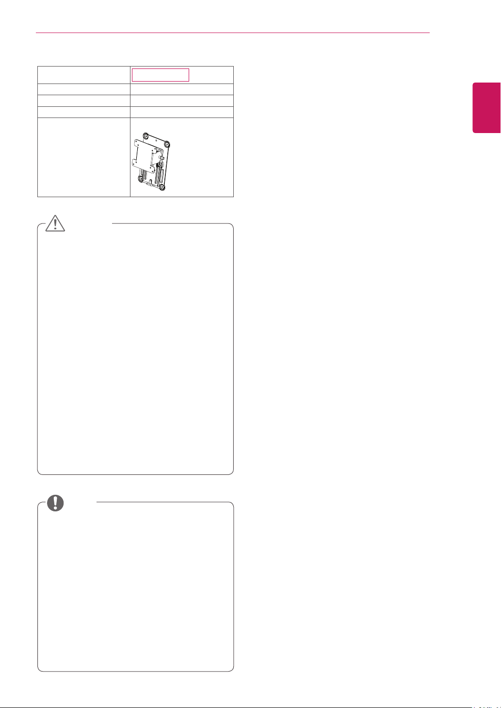
Model
19CNT42K
VESA (A x B)
100 x 100
Stand Screw
M4
Required Screw
4
Wall Mount Plate
(Optional)
RW120
CAUTION
NOTE
12
ENG
English
USING THE MONITOR SET
USING THE MONITOR SET
Connecting Input Signal Cable
y
This monitor supports the *Plug and Play
feature.
*Plug and Play: A feature that allows you to
add a device to your computer, without having
to reconfigure anything or install any manual
drivers.
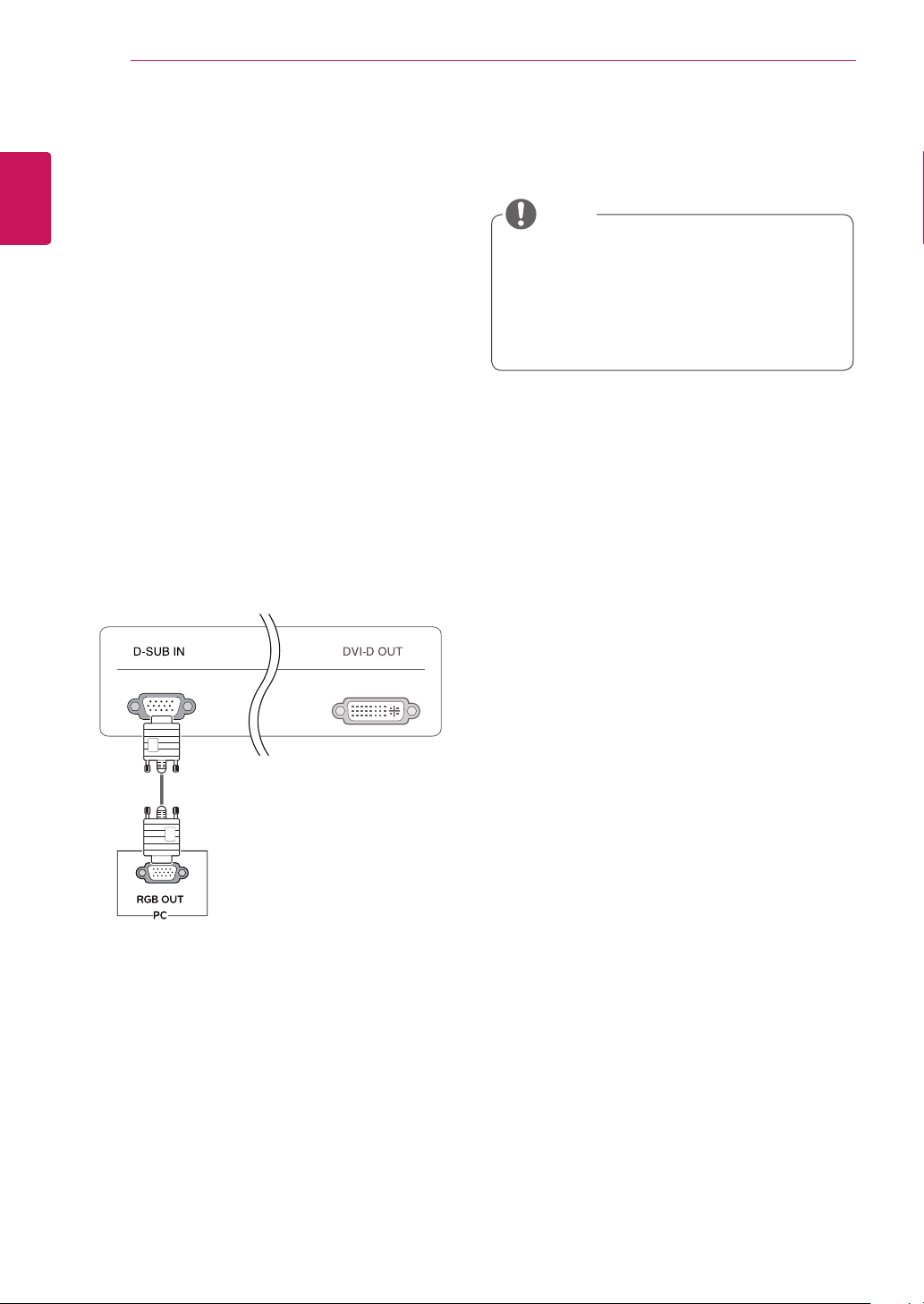
D-SUB IN connection - PC
D-SUB IN transfers analog video signals from the
PC to the monitor.
Connect the monitor to the PC using the provided
15-pin D-SUB signal cable as illustrated below.
NOTE
RGB IN
MONITOR
y
Apple Adapter
An adapter may be needed for Apple
computers. This adapter can be purchased
from Apple.
13
ENG
English
USING THE MONITOR SET
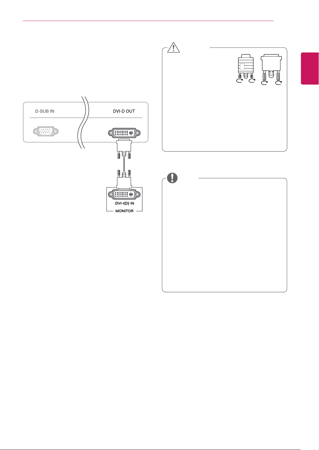
DVI connection
Transfers digital video signals from the Cloud Mon-
itor to an extended monitor.
Connect the Cloud Monitor to an extended monitor
using a DVI cable.
y
To connect the monitor to a computer, use
the appropriate signal cable (LAN and D-
SUB).
y
A converter can be used to convert the DVI-
D input signal to D-SUB input signal.
y
When connecting the power cord to the out-
let, use a grounded (3-hole) multi-socket or a
grounded wall outlet.
y
The monitor may flicker when turned on in an
area of low temperature. This is normal.
y
Sometimes red, green or blue spots may ap-
pear on the screen. This is normal.
y
Connect the input signal
cable and tighten in the
direction of the arrow. To
prevent disconnection
secure the cable tightly.
y
Do not press on the screen for a prolonged
time. This may cause image distortion.
y
Do not display a still image on the screen
for a prolonged time. This may cause image
retention. If possible, use the screen saver.
CAUTION
NOTE
14
ENG
English
USING THE MONITOR SET
Connecting LAN/Peripherals
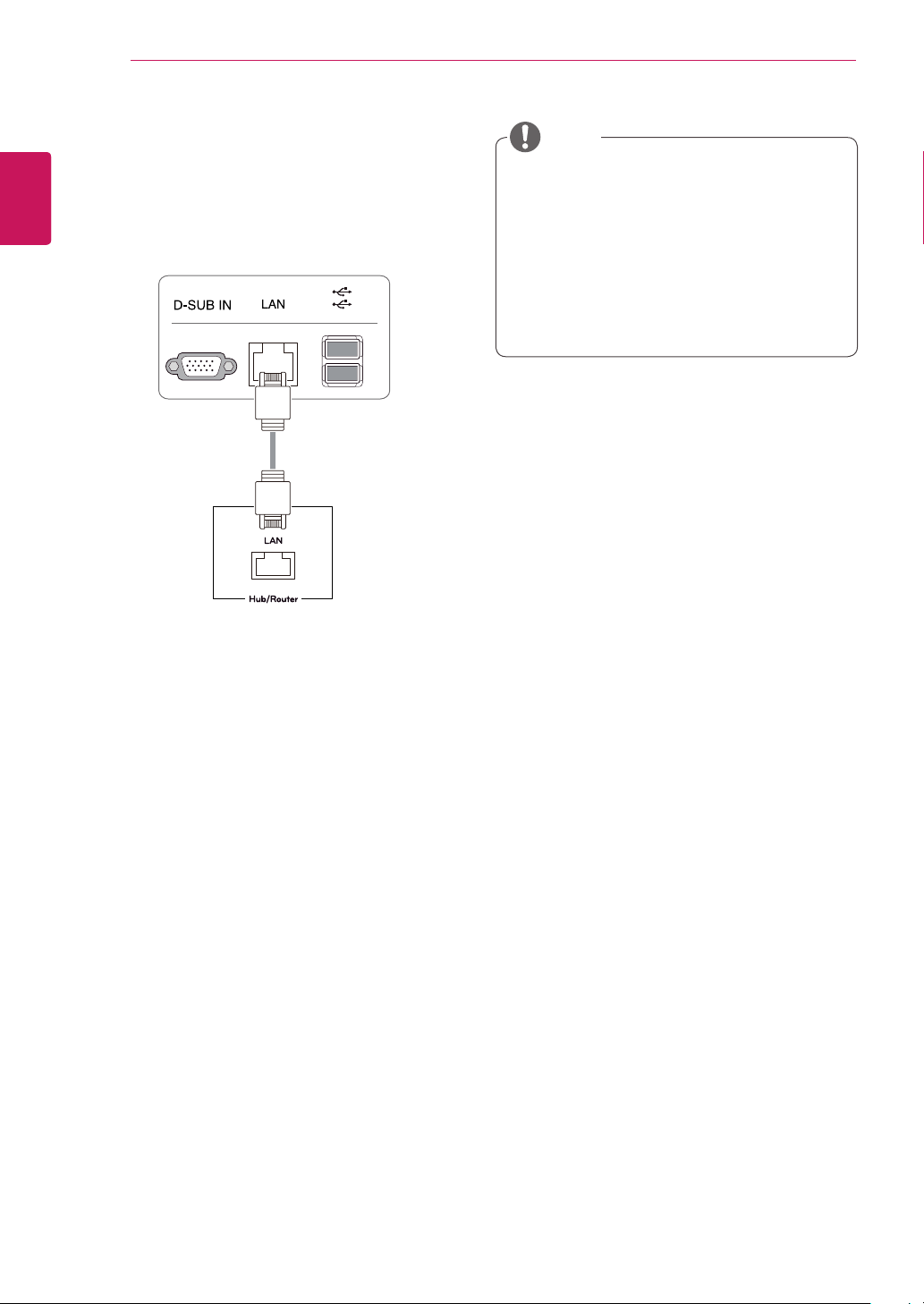
LAN connection
Connect the router or switch to the monitor using a
LAN cable as illustrated below.
y
The LAN cable is sold separately.
y
The following LAN cable type can be used:
Standard: IEEE 802.3 ETHERNET
y
If a device is connected into the earphone
out port via a LAN cable, you can adjust the
volume with the volume icon on PC taskbar.
y
Connect the LAN cable and the peripheral
devices prior to booting up the PC.
NOTE
15
ENG
English
USING THE MONITOR SET
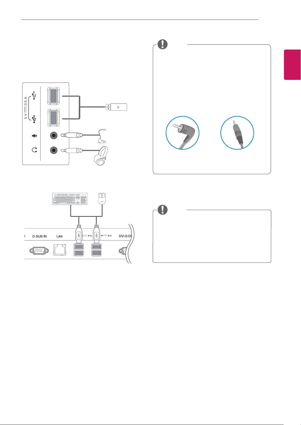
y
Peripheral devices are sold separately.
y
The USB ports on the left and bottom of the
monitor can be used to connect the key-
board, mouse, and other USB devices.
y
Cables with angled plugs may have clear-
ance issues, use straight plugs when pos-
sible.
Angle Type Straight Type
Peripheral device connection
Connect peripheral devices to the monitor using
USB, microphone and headphone ports.
NOTE
NOTE
y
Headphones, speakers or microphone may
not work normally, depending on the server
PC settings.
y
Virtual solutions may affect the functions or
speed of the specific USB storage device.
Left
Bottom
1
1
1
1
16
ENG
English
USING THE MONITOR SET
y
What is "Self Image Adjustment"? This func-
tion runs when the monitor is connected for
the first time and performs automatic image
adjustment for each signal (only available for
analog [D-SUB input] signals) to provide an
optimal screen display.
Self Image Adjustment
Press the power button on the front to turn on
the monitor. When powered on, the
"Self Image
Adjustment"
function will run automatically (only
available for analog [D-SUB input] signals).
NOTE
17
ENG
English
CUSTOMIZING SETTINGS
CUSTOMIZING SETTINGS
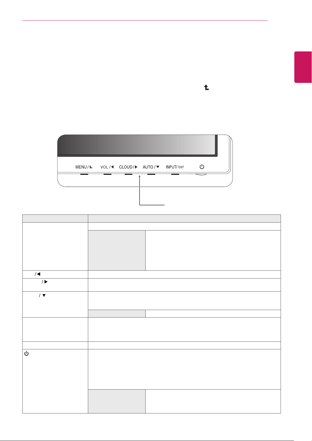
1
Press the desired button on the bottom of the Monitor set.
2
Change the value of the menu item by pressing the buttons on the bottom of the Monitor set.
To return to the upper menu or set other menu items, use the up arrow ( ) button.
3
Select
EXIT
to leave the OSD menu.
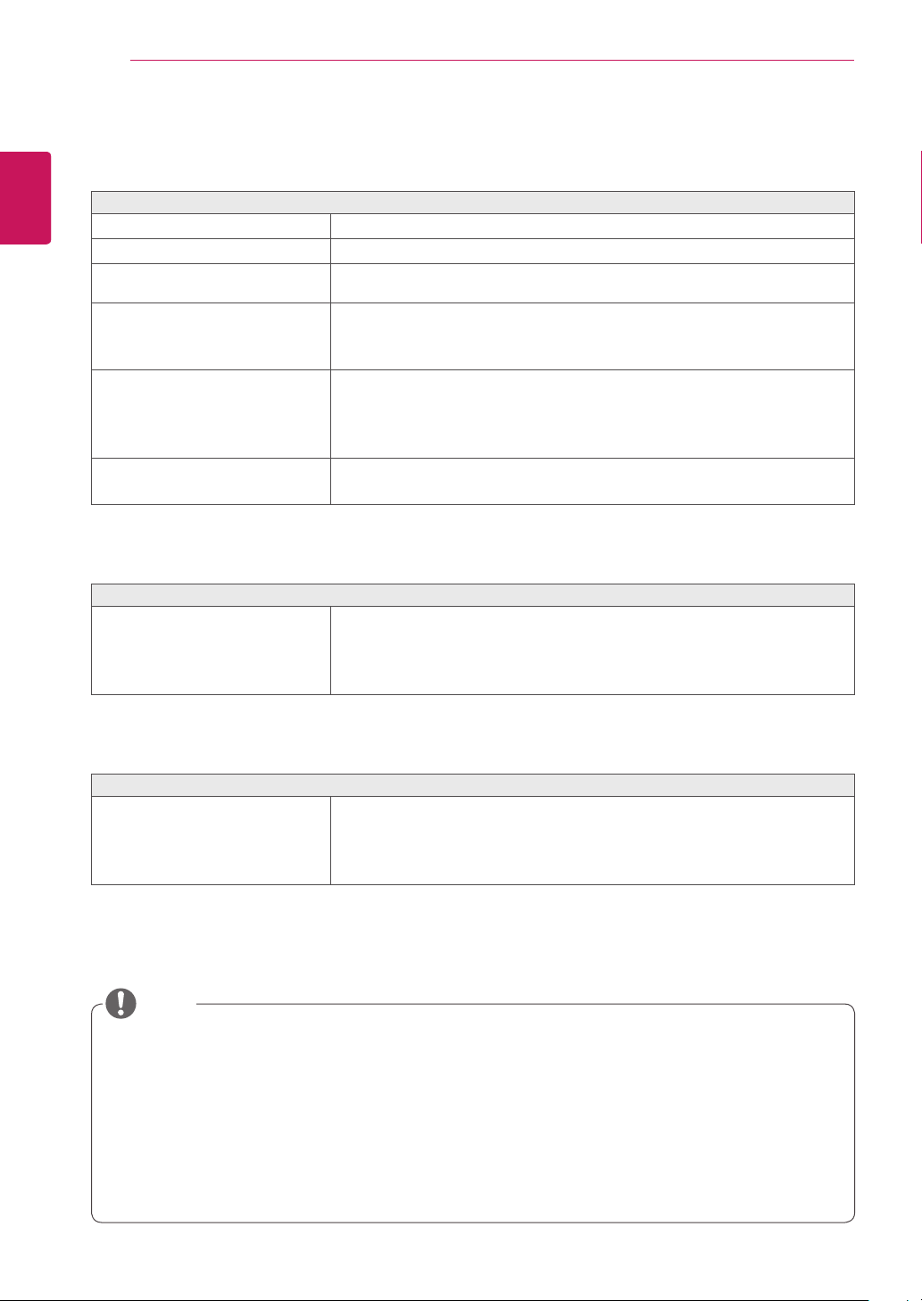
Monitor set Buttons
Button Description
MENU Activates the main menu.
OSD Lock/Unlock
Functions
Locks/unlocks the OSD screen.
y
To lock the OSD screen, press and hold the MENU button
for several seconds. The "OSD LOCKED" message will be
displayed and the screen will be locked.
y
To unlock the OSD screen, press and hold the MENU
button again for several seconds. The "OSD UNLOCKED"
message will be displayed and the screen will be unlocked.
VOL
Adjust the volume of the monitor.(only works in Cloud mode)/the left arrow key.
CLOUD
Disconnects the connection when the key is pressed for a few seconds while in Cloud
mode;the right arrow key.
AUTO To adjust the monitor settings, press the AUTO button on the MONITOR SETUP OSD
menu (only supported for analog signal).
For optimal screen display, use the following resolution.
Optimal Resolution
1440 x 900
INPUT Allows selection of the input signal.
y
If you connect the monitor to a computer using a D-SUB cable, select either the
CLOUD or D-SUB input signal.
y
The initial input signal is D-SUB.
EXIT Exits the OSD menu.
(Power Button)
y
D-SUB Input: Power On/Off
y
CLOUD Input
Monitor Off: Press the power button once then the monitor will be turned off after 5
seconds.
CLOUD Off: Press the power button twice then the monitor and CLOUD connection
will be disabled.
CLOUD On: Press the power button.
Power Indicator
When the monitor is in operating mode, the power indicator
will turn Red (on mode).
When the monitor is in power saving mode, the power indica-
tor will blink Red.
18
ENG
English
CUSTOMIZING SETTINGS
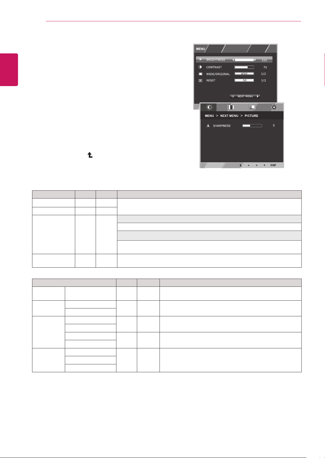
Customizing Settings
Menu Settings
1
Press
MENU
button on the bottom of the Monitor set
to display the
MENU
OSD.
2
Set the options by pressing the ◄ or ► or ▼
buttons.
3
Select the "
NEXT MENU
" button to enter the more
option settings.
4
Select
EXIT
to leave the OSD menu.
To return to the upper menu or set other menu items,
use the up arrow ( ) button.
Each option is explained below.
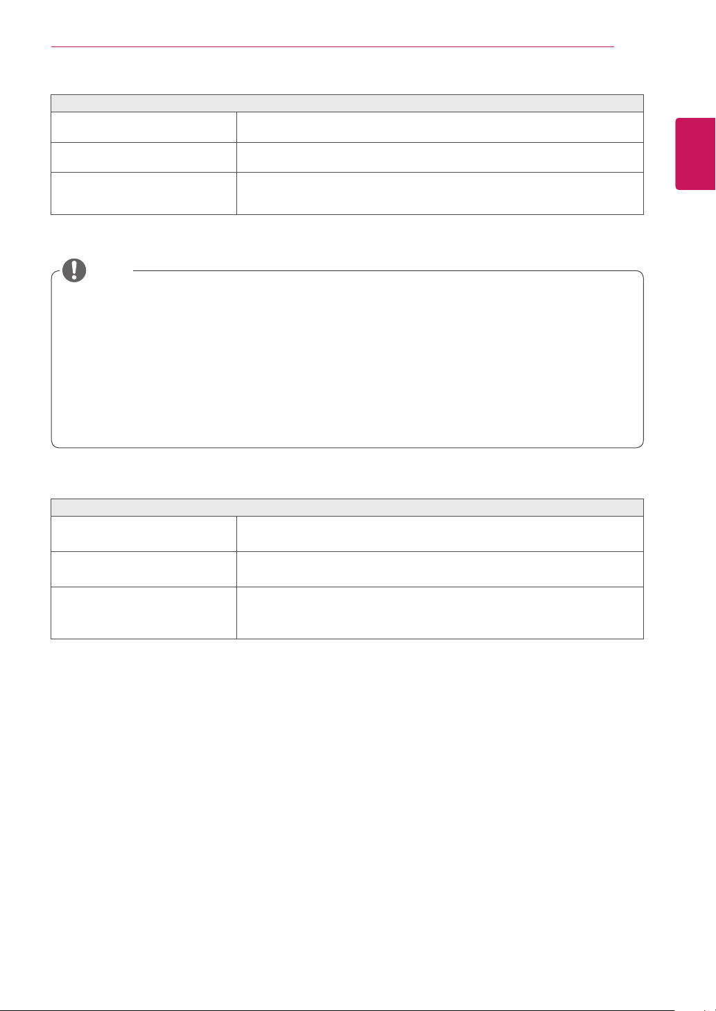
MENU > NEXT MENU D-SUB CLOUD Description
PICTURE
SHARPNESS ● ●
To adjust the clearness of the screen .
COLOR GAMMA
● ●
To customize the color of the screen
COLOR TEMP
DISPLAY HORIZONTAL
●
To adjust the position of the screen
VERTICAL
CLOCK
●
To improve the clarity and stability of the screen
PHASE
OTHERS LANGUAGE
● ●
To customize the screen status for a user's operating
environment
CLOUD
POWER INDICATOR
y
CLOUD:
Using PC via a network.
MENU D-SUB CLOUD Description
BRIGHTNESS
● ●
To adjust the brightness, contrast of the screen
CONTRAST ● ●
WIDE/ORIGINAL
● ●
WIDE
Switch to full screen mode according to input image signal.
ORIGINAL
Change the input image signal ratio to original.
* This function works only if input resolution is lower than Monitor set ratio (16:9).
RESET
● ●
Restore all factory default settings. Press the
◄
,
►
buttons to reset
immediately.
DUAL
WEB
DUAL
WEB
19
ENG
English
CUSTOMIZING SETTINGS
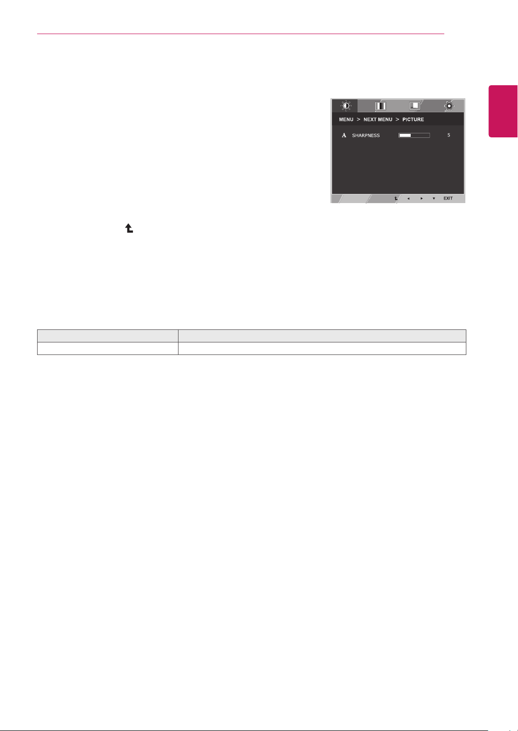
PICTURE
1
Press
MENU
button on the bottom of the Monitor set
to display the
MENU
OSD.
2
Select the "
NEXT MENU
" button to enter the more
option settings.
3
Enter to
PICTURE
by pressing the ▼ button.
4
Set the options by pressing the ◄ or ► buttons.
5
Select
EXIT
to leave the OSD menu.
To return to the upper menu or set other menu items,
use the up arrow ( ) button.
Each option is explained below.
MENU > NEXT MENU > PICTURE Description
SHARPNESS
To adjust the clearness of the screen.
DUAL
WEB
20
ENG
English
CUSTOMIZING SETTINGS
COLOR
1
Press
MENU
button on the bottom of the Monitor set
to display the
MENU
OSD.
2
Select the "
NEXT MENU
" button to enter the more
option settings.
3
Select
COLOR
by pressing the ► button.
4
Enter to
COLOR
by pressing the ▼ button.
5
Set the options by pressing the ◄ or ► or ▼
buttons.
6
Select
EXIT
to leave the OSD menu.
To return to the upper menu or set other menu items,
use the up arrow ( ) button.
Each option is explained below.
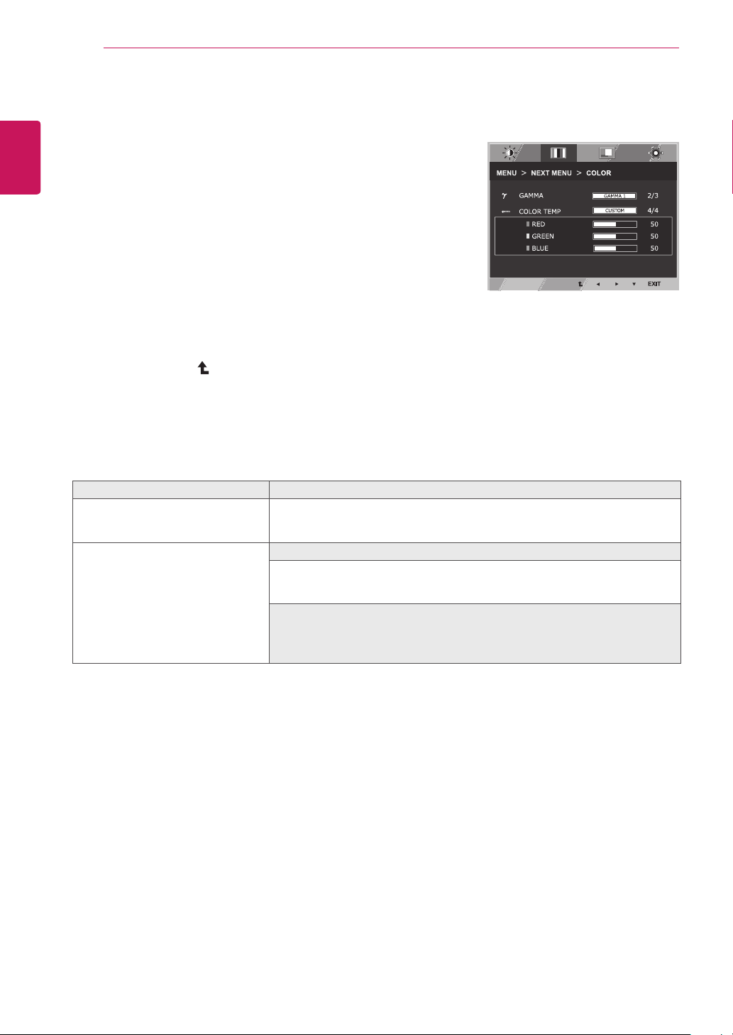
MENU > NEXT MENU > COLOR Description
GAMMA
Set your own gamma value. : GAMMA 0, GAMMA 1, GAMMA 2 on the monitor,
high gamma values display whitish images and low gamma values display
blackish images.
COLOR TEMP CUSTOM
• RED:
Set your own red color levels.
• GREEN:
Set your own green color levels.
• BLUE:
Set your own blue color levels.
Select the screen color.
WARM:
Set the screen to warm color temperature (more red).
MEDIUM:
Set the screen to medium color temperature.
COOL:
Set the screen to cool color temperature (more blue).
DUAL
WEB
21
ENG
English
CUSTOMIZING SETTINGS
DISPLAY
1
Press
MENU
button on the bottom of the Monitor set
to display the
MENU
OSD.
2
Select the "
NEXT MENU
" button to enter the more
option settings.
3
Select
DISPLAY
by pressing the ► button.
4
Enter to
DISPLAY
by pressing the ▼ button.
5
Set the options by pressing the ◄ or ► or ▼
buttons.
6
Select
EXIT
to leave the OSD menu.
To return to the upper menu or set other menu items,
use the up arrow ( ) button.
Each option is explained below.
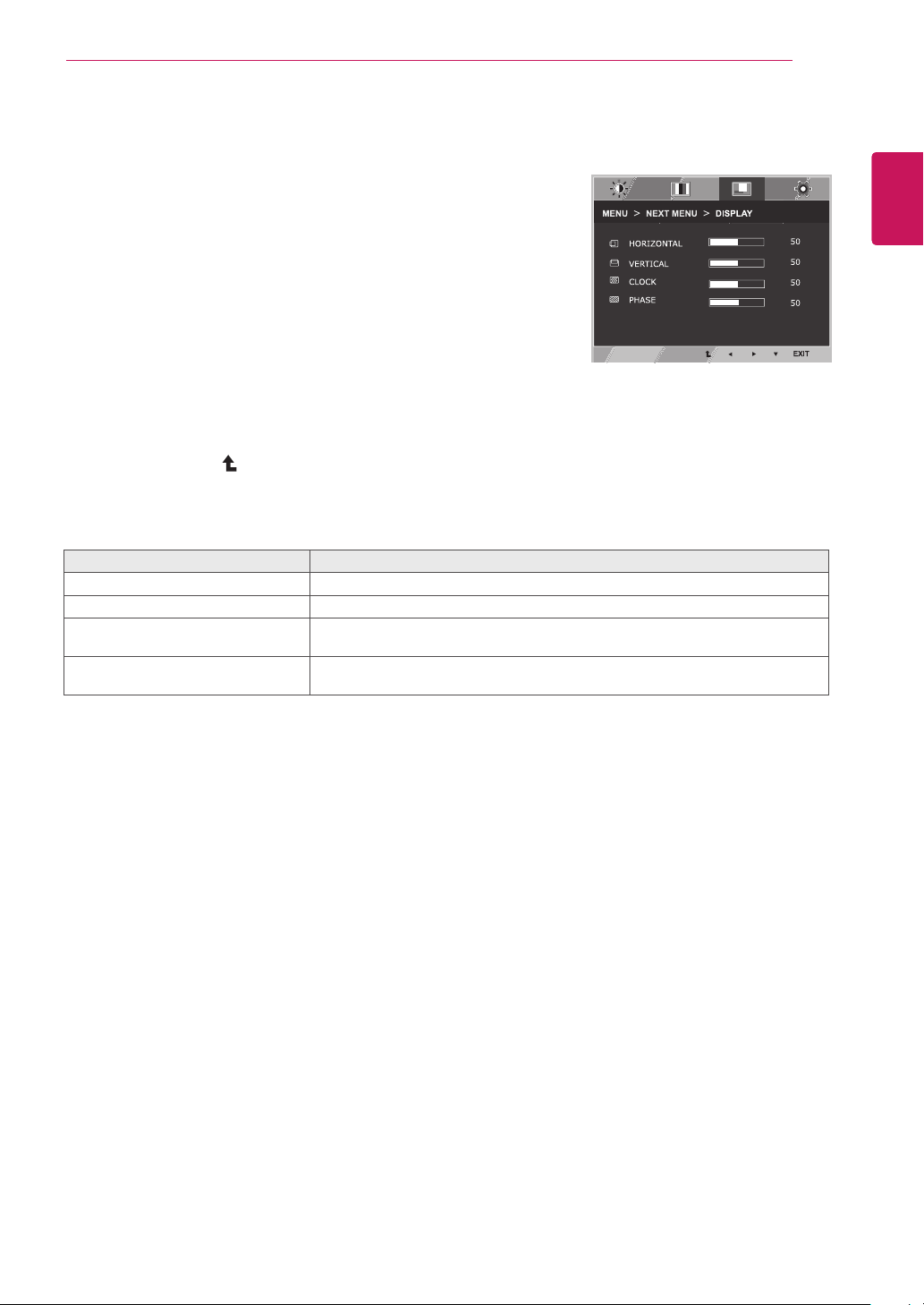
MENU > NEXT MENU > DISPLAY Description
HORIZONTAL
To move image left and right.
VERTICAL
To move image up and down.
CLOCK
To minimize any vertical bars or stripes visible on the screen background.The
horizontal screen size will also change.
PHASE
To adjust the focus of the display. This item allows you to remove any horizontal
noise and clear or sharpen the image of characters.
DUAL
WEB
y
Only available in D-SUB input mode.
22
ENG
English
CUSTOMIZING SETTINGS
OTHERS
1
Press
MENU
button on the bottom of the Monitor set
to display the
MENU
OSD.
2
Select the "
NEXT MENU
" button to enter the more
option settings.
3
Select
OTHERS
by pressing the ► button.
4
Enter to
OTHERS
by pressing the ▼ button.
5
Set the options by pressing the ◄ or ► or ▼
buttons.
6
Select
EXIT
to leave the OSD menu.
To return to the upper menu or set other menu items,
use the up arrow ( ) button.
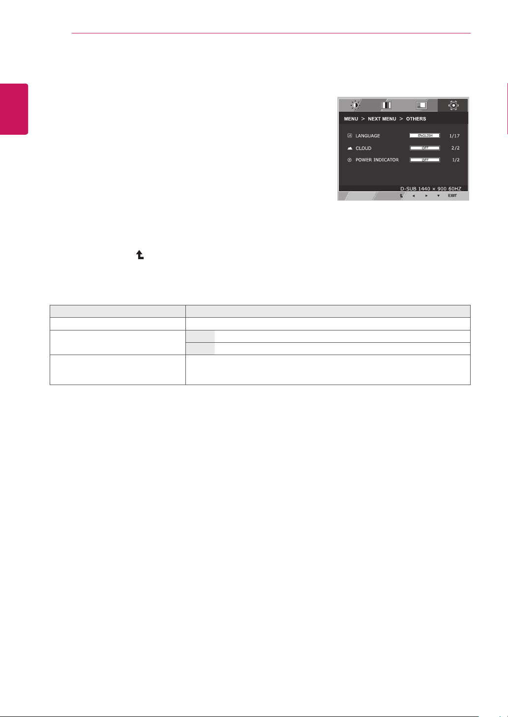
Each option is explained below.
MENU > NEXT MENU > OTHERS Description
LANGUAGE
To choose the language in which the control names are displayed.
CLOUD Off
CLOUD is disabled in D-SUB input mode.
On
CLOUD is enabled in D-SUB input mode.
POWER
INDICATOR
Use this function to set the power indicator on the bottom side of the monitor to
ON or OFF.If you set OFF, it will go off.
If you set ON at any time, the power indicator will automatically be turned on.
DUAL
WEB
23
ENG
English
CUSTOMIZING SETTINGS
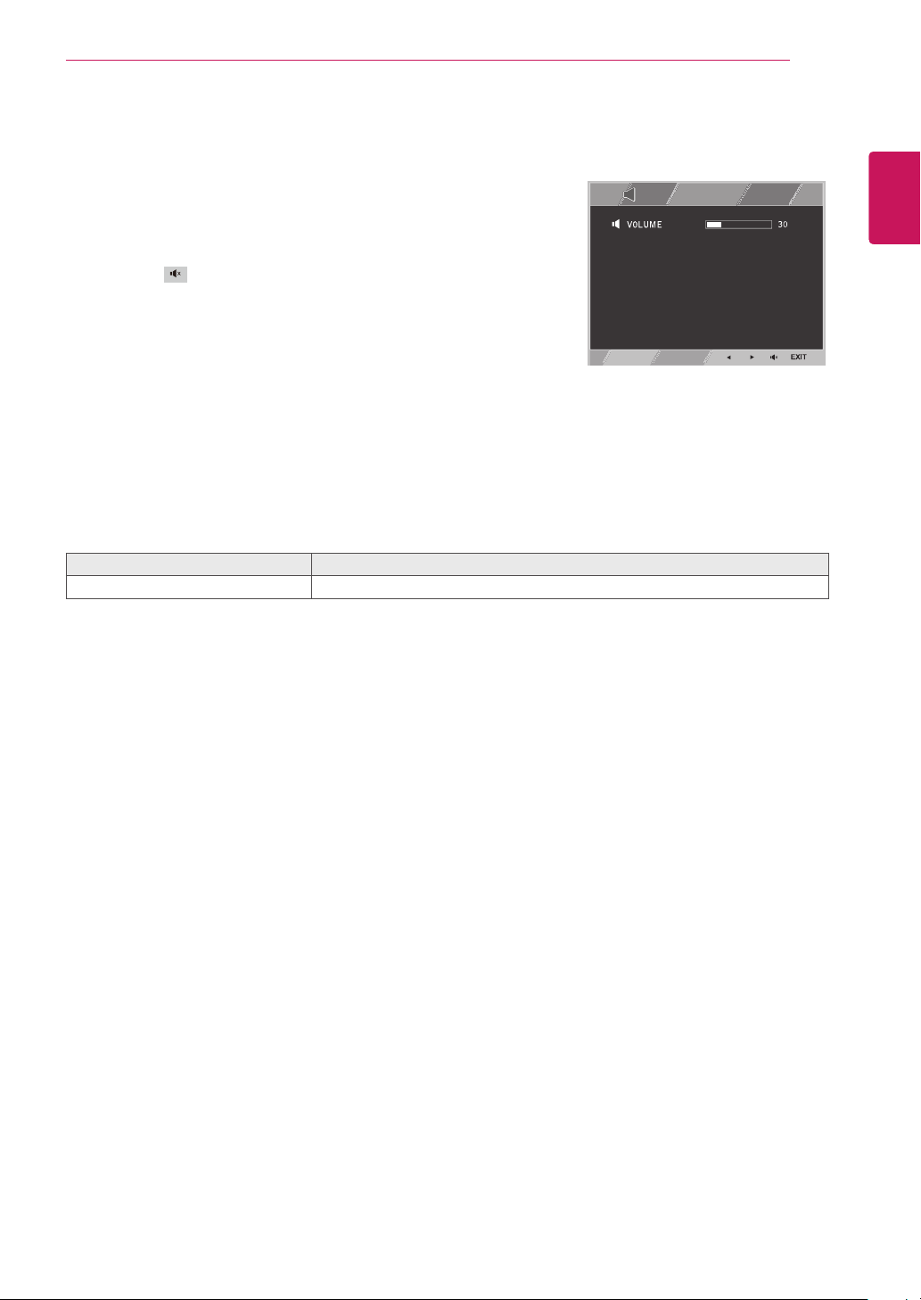
VOLUME
1
Press the
VOL
button at the bottom of the monitor to
display the
VOL
OSD menu.
2
Press the ◄ or ► button to adjust the volume.
3
Press the button to enable or disable Mute.
4
Select
EXIT
to leave the OSD menu.
Each option is explained below.
MENU > NEXT MENU > VOLUME Description
VOLUME
Adjusts the volume (only available in CLOUD input mode).
DUAL
WEB
24
ENG
English
Troubleshooting
TROUBLESHOOTING
Nothing is displayed on the screen
Is the monitor's power cord plugged in?
y
Check if the power cord is correctly plugged in to the outlet.
Is the power indicator on?
y
Check the power indicator.
Is the power indicator displaying as
red?
y
Adjust the brightness and the contrast.
Is the power indicator blinking?
y
If the monitor is in power saving mode, move the mouse or press any
key on the keyboard to switch the display on.
y
Check if the computer is turned on.
Is the "OUT OF RANGE" message
displayed?
y
This occurs when signals transferred from the PC (video card) are out
of the horizontal or vertical frequency range of the monitor. Please see
the "Product Specification" section of this manual to set the appropri-
ate frequency.
Is the "CHECK SIGNAL CABLE"
message is displayed?
y
This is displayed when the signal cable between the PC and the moni-
tor is missing or disconnected. Check the cable and reconnect.
The "OSD LOCKED" message is displayed.
Is the "OSD LOCKED" message
displayed when the MENU button is
pressed?
y
The OSD lock feature is enabled to prevent undesired modification
of the OSD settings. Press and hold the MENU button for a couple of
seconds to unlock the OSD. (The "OSD UNLOCKED" message will be
displayed.)
The screen retains an image.
Does image sticking occur even
when the monitor is turned off?
y
Displaying a still image for a prolonged time may cause damage to the
screen, resulting in the retention of the image.
y
Use a screen saver to protect the screen when using the monitor for a
prolonged period of time.
y
Vertical Frequency:
In order to display an image, the screen must be refreshed dozens of times per
second like a fluorescent lamp. The number of times the screen is refreshed per second is called
vertical frequency or refresh rate and is represented by Hz.
y
Horizontal Frequency:
The time it takes to display one horizontal line is called the horizontal cycle.
The number of horizontal lines displayed in one second
can be calculated by dividing one by the horizontal cycle. This is called horizontal frequency and is
represented by kHz.
NOTE
25
ENG
English
Troubleshooting
The image is displayed abnormally.
Does the display area appear un-
centered?
Pressing the AUTO button will automatically optimize the screen to the current
display mode.
Does the screen exhibit vertical
lines?
Pressing the AUTO button will automatically optimize the screen to the current
display mode.
Does the screen display horizontal
frequencies, or does the text appear
blurred?
Pressing the AUTO button will automatically optimize the screen to the current
display mode.
y
Check if the video card's resolution or frequency is within the range allowed by the monitor and set to
the recommended (optimal) resolution in
Control Panel >
Display > Settings.
y
Failing to set the video card to the recommended (optimal) resolution may result in blurred text, a
dimmed screen, a truncated display area or misalignment of the display.
y
The configuration procedure may differ depending on your computer and/or operating system. Also,
some video cards may not support certain resolutions. If this is the case, contact the computer or
video card manufacturer for assistance.
y
The AUTO option is only available for D-SUB (analog) signals.
The display color is abnormal.
Does the display color appear dis-
colored (16 color)?
y
Set the color to 24 bit (true color) or higher. In Windows, go to Control
Panel > Display > Settings > Color Quality.
Does the display color appear un-
stable or in monochrome?
y
Check if the signal cable is connected properly. Re-connect the cable
or re-insert the PC's video card.
Are there spots on the screen?
y
When using the monitor, pixilated spots (red, green, blue, white or
black) may appear on the screen. This is normal for the LCD screen.
It is not an error nor is it related to the monitor's performance.
NOTE
26
ENG
English
Product Specication
PRODUCT SPECIFICATION
LCD Screen Type 48.1 cm (19 inch) TFT (Thin Film Transistor)
LCD (Liquid Crystal Display) Screen
Diagonal length of the screen: 48.1 cm
Pixel Pitch 0.2835 mm x 0.2835 mm
Resolution Maximum Resolution 1440 x 900 @ 60 Hz
Recommended Resolution 1440 x 900 @ 60 Hz
DVI-D output 1920 x 1200 @ 60 Hz
Video Signal Horizontal Frequency 30 kHz to 66 kHz
Vertical Frequency 57 Hz to 63 Hz
Synchronization Separate Sync
Input Connector 15-pin D-SUB (Analog)
Power Power 19 V 2.3 A
Power Consumption:
CLOUD/D-SUB
On Mode: 17 W(D-sub)/24 W(CLOUD)
Power Saving Mode ≤ 0.5 W(CLOUD mode:8.5 W)
Off Mode ≤ 0.5 W
AC/DC Adapter Type PA-1650-68, manufactured by LITE-ON TECHNOLOGY CORPORATION.
OUTPUT: 19 V 3.42 A
Dimension/
Weight
Monitor Size (Width x Height x Depth)
With Stand 440.2 mm x 370 mm x 225 mm
Without Stand 440.2 mm x 303.2 mm x 47 mm
Weight (Without
Packaging)
4.64 kg
Stand Angle
Adjustment
Forwards/Backwards: -5° to 15° (Monitor)
Environment
Condition
Operating Condition Temperature: 10°C to 35°C; Humidity: 10% to 80%
Storing Condition Temperature: -20°C to 60°C; Humidity: 5% to 90%
The specifications are subject to change without notice.
19CNT42K
27
ENG
English
Product Specication
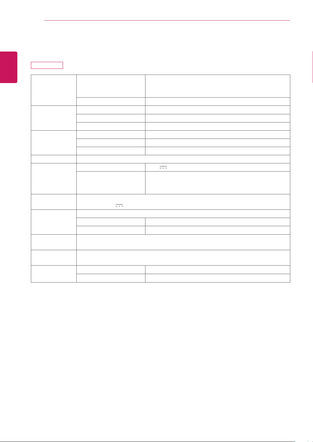
Preset Mode
19CNT42K
Display Modes
(Resolution)
Horizontal
Frequency (kHz)
Vertical
Frequency (Hz)
Polarity (H/V) Remark
720 x 400 31.468 70.08 -/+
640 x 480 31.469 59.94 -/-
800 x 600 37.879 60.317 +/+
1024 x 768 48.363 60 -/-
1440 x 900 55.935 59.888 -/+ Recommended Mode
Power Indicator
Mode LED Color
On Mode
Red (Only 15sec)
Power Saving Blinking Red
Off Mode Off
28
ENG
English
Proper Posture
PROPER POSTURE
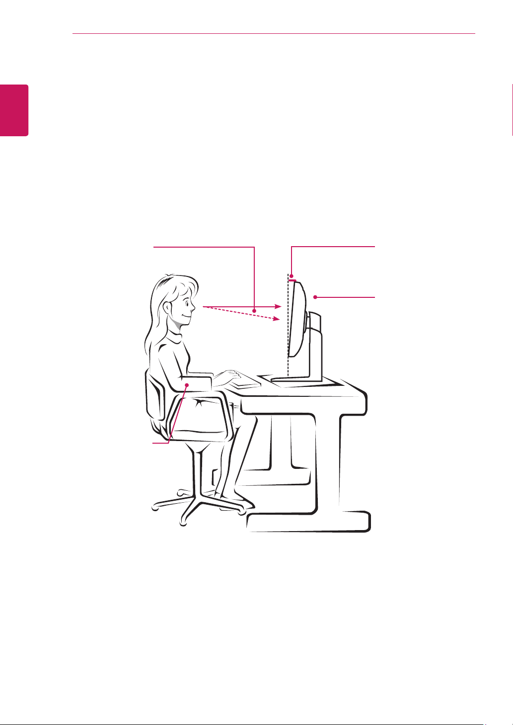
Proper posture for using the monitor
Adjust the angle so that the screen is slightly lower than your eyes.
y
Using the monitor for a prolonged period of time can cause eye fatigue. Take a 10-minute break every
hour.
y
The stand is designed to best support the monitor when the optimal conditions are selected.
Adjust the angle of the monitor from -5° to 15° to obtain the best view of the screen.
You should be
looking
slightly down at
the screen.
Place your hands gently
on the keyboard,
keeping your arms bent at
the elbows
and extended horizontally
in front of you.
Adjust the angle
from -5° to 15°
so that there is no re-
flection
or glare from the
screen.
29
ENG
English
USING CITRIX CLOUD MONITOR
USING THE CITRIX CLOUD MONITOR
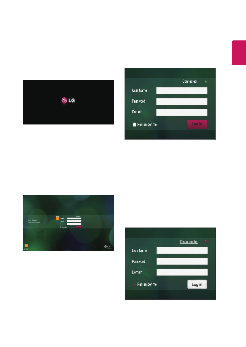
Initial Screen
After power on, restart or factory reset, the LG logo
is displayed as shown below.
[Log in Window]
Enter user name, password and domain to con-
nect to the VDI server.
y
Network status:
If a network connection is
available, the message "Connected" next to the
round green icon is displayed. If a network con-
nection is not available, the message "Discon-
nected" next to the round red icon is displayed.
When a network connection is in progress, the
message "Connecting..." next to the round red
icon is displayed.
When no network connection is available, the
Log in button is deactivated.
Log in Screen
When the power is on, the LG logo appears and
then the Log in screen appears as shown below.
[1] Log in window:
enter user name, password.
and domain to connect to the VDI server.
[2] MENU button:
use this button to change and
view the power and basic settings of the device.
y
Remember me:
you may select this checkbox to
store a log in information for future use.
y
Log in:
select this button to connect to the VDI
server.
30
ENG
English
USING CITRIX CLOUD MONITOR
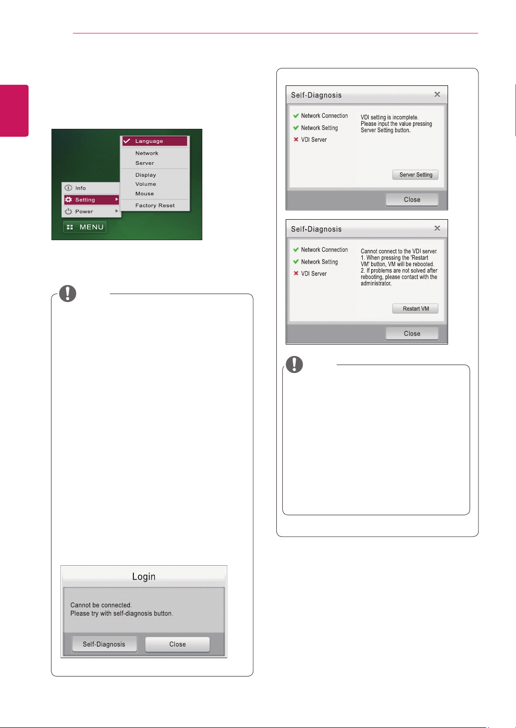
[MENU button]
Use this button to change and view the power and
basic settings of the device.
y
If you place the mouse over a top menu item, its
context menu is displayed.
y
Up to 80 characters are allowed for the user
name, password and domain.
y
Allowed characters follow the Windows Ac-
tive Directory rules that control the genera-
tion of a user account.
y
The user name and domain are not cas-
esensitive, but the password is.
y
If you click the"Connected "or
the"Disconnected" link, the network setting
screen appears (MENU > Setting).
y
If you fail to connect to the server after
click-ing the Log in button, the "Self-Diagno-
sis" pop-up message is displayed. The "Self
Diagnosis" function enables the system
to check and diagnose problems with the
network connection, network setting or VDI
server.
y
The time required to connect to the VDI
server may vary depending on the network
environment.
NOTE
NOTE
y
If the VDI server setting is incomplete,
select the Server Setting button to go to
MENU > Setting.
y
When VDI server has a problem, VMcan
be restarted through ‘Restart VM’ button.
Restarting VM time will take a few minutes.
However, eZ-CMS should be required to
use this function. eZ-CMSis a software
program for managingthen cloud products
provided by LG Electronics.
31
ENG
English
USING CITRIX CLOUD MONITOR
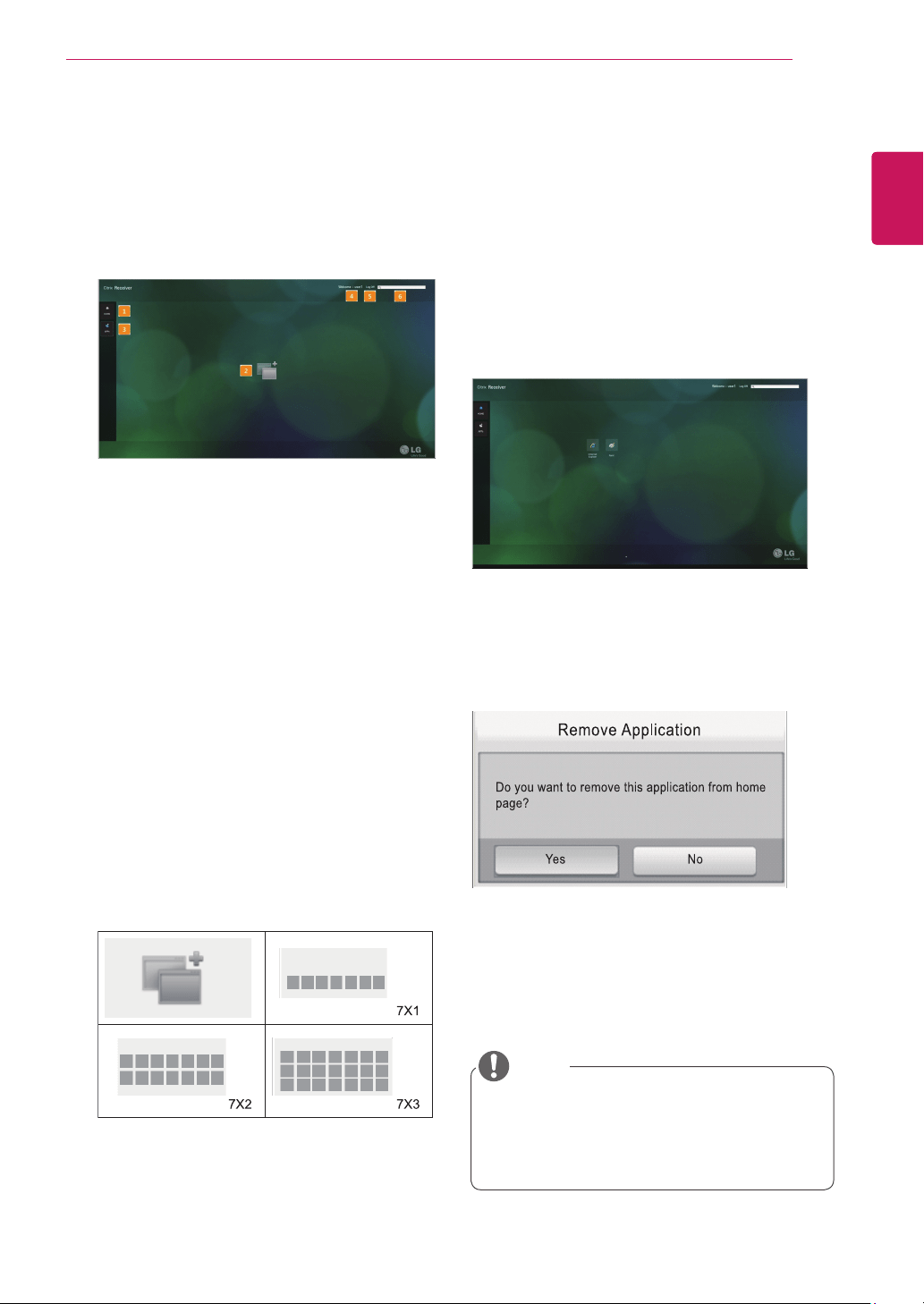
Application Screen
If there is only one virtual OS for the user account,
the system is connected to the OS directly.
If there is more than one OS, the following screen
appears.
[1] Home
y
After logging in, the Home tab is displayed on
the screen. The applications you added are also
displayed as icons.
[2] Applications
y
You can arrange the application icons on the
screen.
y
A single page can have up to seven icons in
each row and three icons in each column. (If the
monitor is rotated to portrait mode, a single page
can have up to four icons in each row and five
icons in each column.)
y
If there are 21 applications or more, additional
pages are added after the first page. Up to five
pages can be added. (In portrait mode, if there
are 20 applications or more, additional pages
are added after the first page. You can add up to
100 applications on the screen.)
y
Arrangement of applications complies with the
guidelines provided by CITRIX.
[3] Adding applications
y
A list of applications that can be added is dis-
played.
y
When you select an item, focus is given to the
item and the sub-list is displayed.
y
Double-click an application in the sub-list to add
it.
y
Display of applications complies with the guide-
lines provided by CITRIX.
y
The application added is displayed on the screen
as shown below.
y
Double-click the application to start it.
y
Clicking the application icon once shows the [x]
button. If you click this button, the following mes-
sage is displayed. To remove the application,
select the "Yes" button.
[4] User name:
the user ID of the logged user is
displayed.
[5] Log off:
select this button to return to the Log
in window.
[6] Search:
you can enter the application you want
to search here.
y
User should necessarily perform "Logoff"
inorder to save the added application.
y
The added application is only stored on the
inside of the same cloud monitor.
NOTE

32
ENG
English
USING CITRIX CLOUD MONITOR
Setting Button
With this button, you can set the network, server
and language for the Cloud monitor.
[Language Setting]
You can set the language used in the Log in
window screen of the Cloud monitor. After setting
the language, click the "OK" button. The default
language is set to "English". The Log in window
supports 11 languages: Chinese, Japanese, Eng-
lish, Korean, French, Russian, German, Spanish,
Hungarian, Portuguese and Swedish.
[Network Setting]
You can configure a wired network.
Power Button
On the Log in screen, if you click MENU > Power,
you can select "Power Off" or "Restart".
[Power Off]
Select the "Power Off" menu and press the "Yes"
button in the Shutdown pop-up window to exit the
system.
[Restart]
Select the "Restart" menu and press the "Yes"
button in the Restart pop-up window to restart the
system.
33
ENG
English
USING CITRIX CLOUD MONITOR
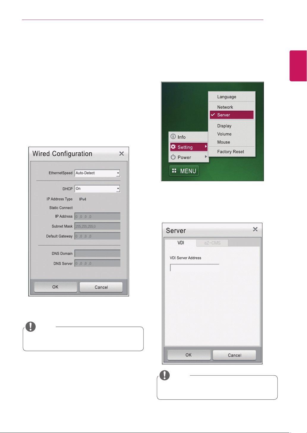
[Server Setting]
Go to Setting > Server to set the VDI server and
eZ-CMS server addresses for Citrix. eZ-CMS is a
software program for managing the cloud products
provided by LG Electronics.
VDI Server Setting
y
Enter the VDI server address you want to ac-
cess.
Wired Configuration
y
Ethernet speed: sets the speed of a wired
network. You can select Auto-Detect, 10Mbps,
100Mbps or 1000Mbps.
y
DHCP: sets the DHCP mode. When DHCP is
set to On, the IP address from the DHCP server
is populated.
y
Static Connect: when DHCP is set to Off, the
fields for detailed setting are activated. Enter the
value in the IP Address, Subnet Mask, Default
Gateway, DNS Domain and DNS Server fields
and press the OK button to complete the con-
figuration
y
Ethernet speed may vary depending on the
network environment.
NOTE
y
User will not be required to enter "http://"
or"https://" in VDI server address.
NOTE
34
ENG
English
USING CITRIX CLOUD MONITOR
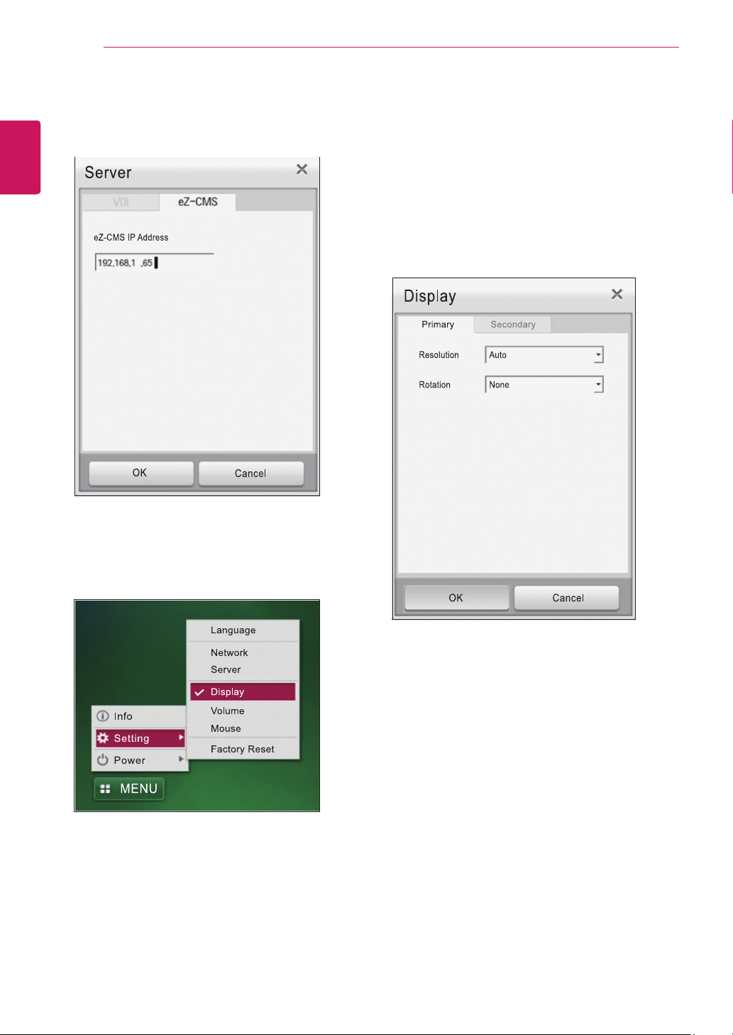
eZ-CMS Setting
y
Enter the eZ-CMS server address to connect to
the management software.
[Display Setting]
You can set the display mode of the cloud monitor.
Primary Display Setting
y
Resolution: sets the resolution of the monitor.
19CNT42K: the Cloud monitor supports the fol-
lowing resolution: Auto, 1440x900 and 1024x768.
If it is set to "Auto", the resolution is set to the
optimal resolution.
y
Rotation: sets the monitor orientation to None,
Left 90 or Right 90.
35
ENG
English
USING CITRIX CLOUD MONITOR
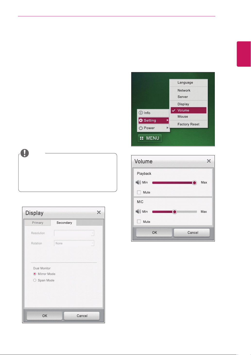
Secondary Display Setting
y
Resolution: sets the resolution of the monitor.
The following options are available for the reso-
lution supported by the DVI monitor.
If it is set to "Auto", the resolution is set to the
optimal resolution.
y
Rotation: sets the monitor orientation to None,
Left 90 or Right 90.
y
Dual Monitor: you can select from Mirror Mode
and Span Mode.
- Mirror Mode displays the same image on the
secondary display as the one on the primary
display.
- Span Mode extends the primary display to the
secondary display.
In Mirror Mode, the Resolution and Rotation op-
tions are deactivated.Click the "OK" button to set
the system with the selected values.
[Volume Setting]
You can set the volume for Playback and MIC. Se-
lect the “Mute” checkbox to mute the playback and
mic volume. The volume scroll bar for playback is
set to max by default.
y
The secondary display settings are activated
and can be applied only when the DVI monitor
is connected.
y
The secondary display can support up to
1920x1200 resolution.
NOTE
36
ENG
English
USING CITRIX CLOUD MONITOR
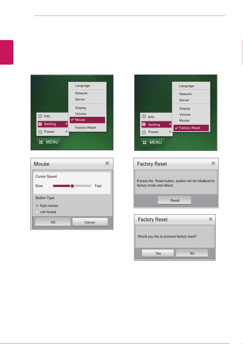
[Mouse Setting]
You can set the cursor speed by dragging the
scroll bar. Select from "Right Handed" and "Left
Handed" under the "Button Type" menu to change
the function of the mouse button.
[Factory Reset]
This menu resets the system to the factory default
settings and reboots it.
Click the "Reset" button in the Factory Reset pop-
up window and then the "Yes" button to reset the
system.
37
ENG
English
USING CITRIX CLOUD MONITOR
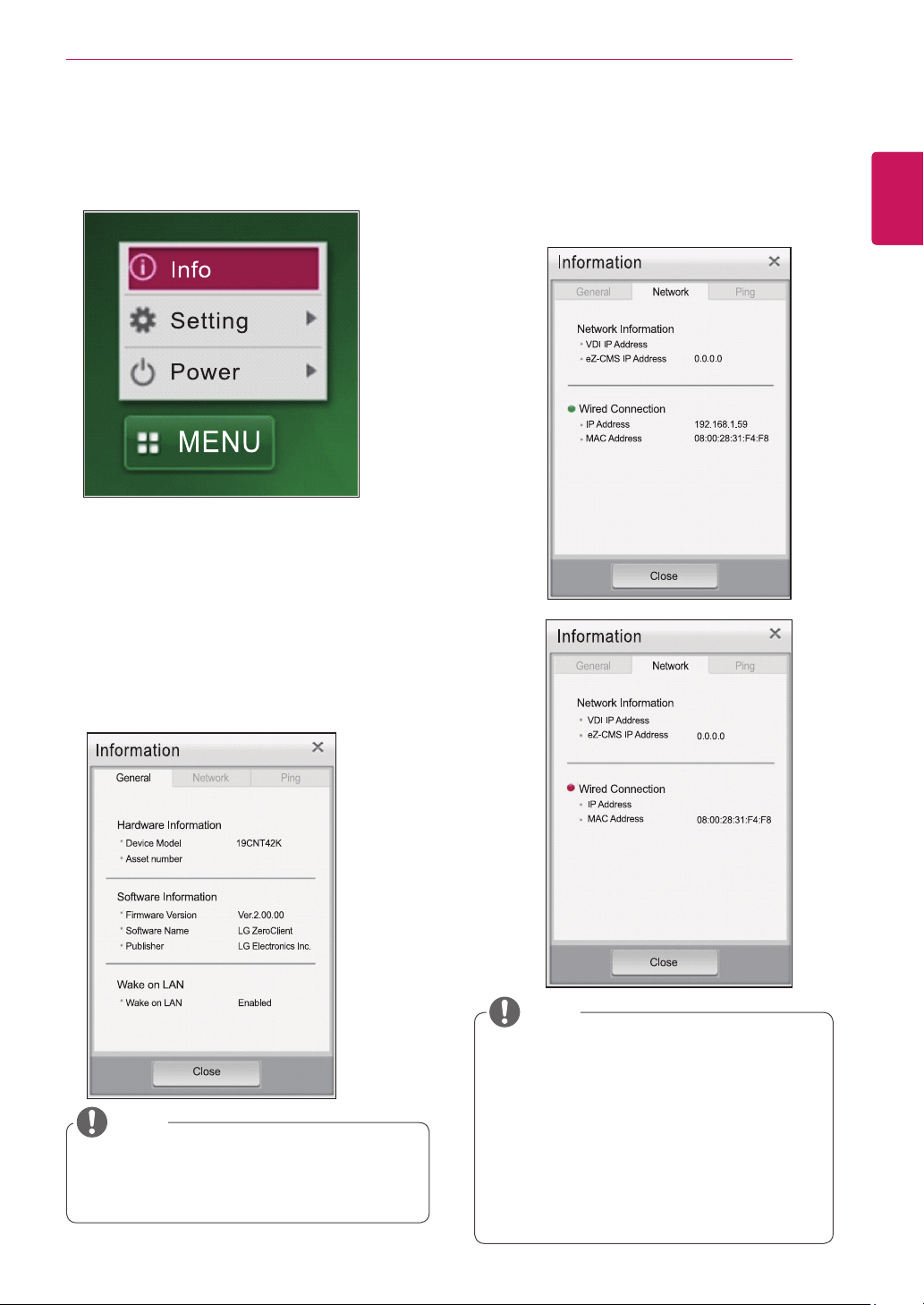
Info Button
Press the "Info" item to display the pop-up window
for the system information.
[General Tab]
This tab shows hardware information, software
information and Wake on LAN.
y
Hardware Information: shows the device model
(Displayed as 19CNT42K) and asset number.
The asset number can be set in eZ-CMS.
y
Software Information: shows the firmware ver-
sion, software name and publisher.
y
Wake on LAN: shows whether or not Wake on
LAN is enabled.
[Network Tab]
This tab shows network-related information.
y
Network Information: shows the set VDI IP ad-
dress and eZ-CMS IP address.
y
Wired Connection: shows the IP address and
MAC address of the wired network.
y
Wake on LAN can only be set in eZ-CMS.
y
eZ-CMS is a software program for managing
the cloud products provided by LG Electronics.
NOTE
y
While detecting the IP address, the IP ad-
dress for the wired network connection is
empty and the round red icon is displayed
as in the Log in window.
y
The MAC address indicates the unique infor-
mation of the device regardless of the wired
network connection.
y
If the VDI address is not set, the address is
empty and the eZ-CMS server address is
displayed as 0.0.0.0.
NOTE

38
ENG
English
USING CITRIX CLOUD MONITOR
[Ping Tab]
On the Ping tab, you check the network connection
to a specific IP address or host from a local client
as well as local network status.
y
Only the IP address or host name can be en-
tered; other options for Ping cannot be used.
y
If you select the "Clear log" button, only the
current information will be deleted.
y
A loading image is displayed while the Ping
function is used, and other buttons are dis-
abled.
NOTE
Pop-up Message Linked to
eZ-CMS
[1] Shutdown/Restart message
This pop-up window is used for performing shut-
down or restart without delay or postponing shut-
down or restart by the eZ-CMS manager due to a
change in the device's status.
y
The default standby time for shutdown/restart is
10 minutes.
y
After 10 minutes, the system restarts or shuts
down. You can postpone the operation for 30
minutes or one hour using the "Remind me in"
option The "Remind me in" option is set to 30
minutes by default.
y
If you select the "Restart Now" or "Shutdown
Now" button, the system restarts or shuts down
without delay.
y
If you select the "Postpone" button, the system
displays this pop-up message again 10 minutes
before the time set in the "Remind me in" field.
y
If you select the "Deny" button, the system does
not restart or shut down.
39
ENG
English
USING CITRIX CLOUD MONITOR
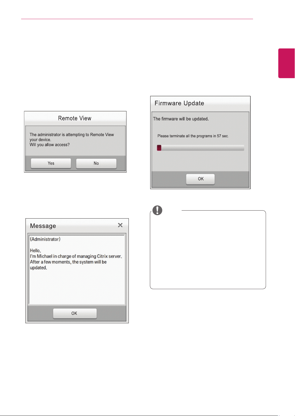
[2] Remote View
This pop-up window is displayed when the eZ-
CMS manager asks for the remote view.
y
Selecting the "Yes" button displays the user's
screen on the manager's screen.
y
The eZ-CMS manager can perform remote
management as well as remote view.
y
The message disappears automatically after 15
seconds, even if the user does not select the
Remote View button.
[3] Administrator Message
This pop-up window is displayed when the eZ-
CMS manager sends a message to the user.
[4] Firmware update notice
The pop-up window is displayed when the eZ-CMS
manager sends the system firmware update com-
mand to the user.
After 60 seconds, the firmware is updated auto-
matically. If you press the "OK" button within 60
seconds, the firmware update starts immediately.
y
If there are problems in the firmware file
uploaded to the FTP server, the "Firmware
file downloading has failed" message will be
displayed.
y
Do not turn off the monitor or the power while
the firmware update is in progress. It will take
about 10 to 15 minutes to complete the firm-
ware update.
y
The required time for firmware update may
vary depending on the network environment.
NOTE
MODEL
SERIAL
Make sure to read the Safety Precautions before
using the product.
Keep the Owner’s Manual (CD) in an accessible
place for future reference.
The model and serial number of the SET is
located on the back and one side of the SET.
Record it below should you ever need service.
As an ENERGY STAR Partner LGE
U. S. A.,Inc. has determined that this
product meets the ENERGY STAR
guidelines for energy efficiency.
ENERGY STAR is a set of power-saving
guidelines issued by the U.S.Environmental
Protection Agency(EPA).
To obtain the source code under GPL, LGPL,
MPL and other open source licenses, that is
contained in this product, please visit http://
opensource.lge.com .
In addition to the source code, all referred
license terms, warranty disclaimers and
copyright notices are available for download.
LG Electronics will also provide open source
code to you on CD-ROM for a charge covering
the cost of performing such distribution (such
as the cost of media, shipping and handling)
upon email request to opensource@lge.com.
This offer is valid for three (3) years from the
date on which you purchased the product.
*above information is only for USA FCC Regulatory
Declaration of Conformity
Trade Name: LG
Model : 19CNT42KL
Responsible Party: LG Electronics Inc.
Address : 1000 Sylvan Ave. Englewood Cliffs
NJ 07632 U.S.A
TEL: 201-266-2534
y
The way to update a firmware file is to download it from the web site. http://stg.lgecommercial.com
If you require technical assistance, please contact the local service representative.
NOTE