•Brings you only the heat you need, when you need it, and adjusts automatically to save you money
•You define your comfort—maintains your room temperature within one degree
•Our most thoughtful design features:
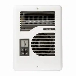
Large digital display shows your room temperature and heating mode
Easy, intuitive one-touch controls
Night/Away and Max/Min options for extra savings and safety
Improve air circulation and add comfort in off-sea- son with three fan-only speeds
Easily replaces many Com-Pak Series heaters: C, CB, CM, CS or X
•Eliminate guesswork with smart power supply sensor that self adjusts to your voltage
•Automatic high temperature safety shutoff
•Your Energy Plus heater has been thoroughly tested and is guaranteed with a limited 5-year warranty
Energy Plus Models
Line Voltage
Models
Watts
Amps
120
CE163T
1000
8.3
208
1500
7.2
240
1600
6.7
240 only
CE162T
1600
6.7
208 only
CE168T
1600
7.7
120
CE083T
500
4.2
208
750
3.6
240
800
3.3
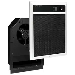
Energy Plus Model With Built-In Controller
Wall Thermostat Not Required
TOOLS REQUIRED:
•Phillips Screwdriver
•Straight Screwdriver
•Wire Strippers
•Utility Knife
•(4) 1½" Wood Screws
•(2) Insulated Wire Connectors
•(1) Strain Relief Connector
Before you begin, you should know...
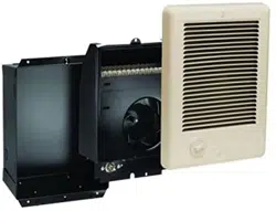
...about the Cadet Energy Plus heater
The Cadet Energy Plus Heater provides comfort to a room by using an efficient, variable speed fan to circulate the warm air, and an intelligent thermostat to deliver precise temperature control.
Your heater is designed to save energy and run at a low speed once the desired room temperature is reached. This is normal operation that reduces on/off cycles and improves overall performance and comfort.
Your heater also has a cool down feature that may run the fan for up to 10 minutes after switching to STOP HEATING/NO FAN mode. This is typical. The air coming out of the heater may feel cool, but it’s actually residual heat moving into the room.
...some installation facts
•Install vertically only. The recommended height is 24 inches (61 cm) from the floor to the bottom of the wall can.
•The heater must not be installed in the floor or ceiling, even if you are replacing an existing heater that was installed in either of these locations.
•Installation on an inside wall is recommended.
...a wall thermostat may not be used
Your Energy Plus heater is equipped with a unique built-in thermostat that both regulates the heat output and provides precise tem- perature control. If replacing a heater controlled by an existing wall thermostat, remove wall thermostat from the heater circuit and cover the hole with a faceplate.
TO REMOVE AN EXISTING WALL THERMOSTAT FROM HEATER CIRCUIT
1.Make sure power is off at the main disconnect panel.
2.Remove wall thermostat mounting screws.
3.Pull the thermostat away from the wall and count the wires.
4.A. If you count 2 black supply wires and 2 white supply wires in the box, disconnect thermostat and connect the 2 black wires together with a wire connector (not included). Connect the 2 white wires together with another wire connector (not included). Connect all ground wires together.
B. If you have 1 black supply wire and 1 white supply wire, disconnect thermostat and connect the black and white wires together with a wire connector (not included). Connect all ground wires together.
C. If you have more than 2 black or 2 white wires, please consult a qualified electrician.
5.If you have a metal junction box, it must be grounded (use a grounding screw or clip).
6.Install a blank faceplate (not included) over the exposed junction box.
INSTALLATION INSTRUCTIONS
1. WARNING
Verify that the electrical supply wires are the same voltage as the heater.
2.If replacing an existing heater, check the label of the old heater for voltage and wattage information.
3.All electrical work and materials must comply with the National Electric Code (NEC), the Occupational Safety and Health Act (OSHA), and all state and local codes.
4.If you need to install a new circuit or need additional wir-
ing information, consult a qualified electrician.
5.Use copper conductors only.
6.WARNING
Risk of Electrical Shock. DO NOT install the heater direct- ly above bathtub or sink. DO NOT install in shower stall area (Manufacturer recommends a minimum 2 foot (61 cm) clearance).
7.Heater must be installed in a wall can:
Model CE Wall Can CC
8. WARNING
Risk of Fire. DO NOT install the heater in a floor, in the ceil- ing, below a towel bar, behind a door, or anywhere the air discharge may be blocked in any manner.
9.WARNING
Fire or Explosion May Occur. A heater has hot and arcing or sparking parts inside. Do not use it in areas where gasoline, paint, or flammable vapors or liquids are used or stored.
10.WARNING
Risk of Electrical Shock. Connect grounding lead to ground- ing screw provided. Keep all foreign objects out of heater.
11.WARNING
Risk of Fire. This heater is hot when in use. Caution—High Temperature. Risk of Fire. Keep electrical cords, drapery, furnishings, and other combustibles at least 3 feet (0.9 m) from the front of the heater and 6 inches (15.2 cm) above and on both sides.
Part One _
REPLACEMENT: If you are replacing an existing Com-Pak model, proceed to Part Two, page 5. Confirm that your existing wall can is mounted flush with outside of sheetrock. Adjust if necessary.
PLACEMENT: Install vertically. Heater is not approved for horizontal or ceiling mount applications. ADA requirements are met if the heater is installed between 12½ inches (31.8 cm) and 42 inches (1.1 m) from the floor. The recommended height is 24 inches (61 cm) from the floor to the bottom of the wall can (See Figure 4).
CONTROLS: A built-in digital thermostat is included. May not be used with a wall thermostat.
How do I install for new construction?
STEP 1 Mount The Wall Can
REQUIRED MINIMUM distance of ¾ inches (1.9 cm) from adja- cent surfaces, such as walls, and 4½ inches (11.4 cm) from the floor (See Figure 4). Cadet recommends 24 inches (61 cm) from floor for optimum performance. Heaters must be spaced at least 3 feet (0.9 m) apart.
Secure the wall can to the stud with 2 screws (not included). (See Figures 1 and 2). As an option, the rubber shim provided may be attached to side of wall can to square the wall can to the stud.
Figure 1
Face of wall can must extend ½ inch (1.3 cm) or ⅝ inch (1.6 cm) from face of stud to allow for thickness of sheetrock.
Figure 2
Attach wall can to stud with screws (not included) through holes provid- ed in wall can. IMPORTANT: wall can should be mounted flush with outside of sheetrock.
STEP 2 Route Supply Wires
Route supply wire from the circuit breaker to the heater. Remove a knockout from the wall can and attach the supply wire with a strain relief connector (not included) leaving a minimum of 6 inch- es (15.2 cm) wire lead. Connect supply ground wire to grounding screw in wall can (See Figure 3).
Proceed to Part Two.
How do I install in an existing wall?
STEP 1 Cut A Hole In The Wall
REQUIRED MINIMUM distance of ¾ inches (1.9 cm) from adjacent surfaces, such as walls, and 4½ inches (11.4 cm) from the floor (See Figure 4). Cadet recommends 24 inches (61 cm) from floor for optimum performance. Heaters must be spaced at least 3 feet (0.9 m) apart.
Cut a hole 8 inches (20.3 cm) wide by 10¼ inches (26 cm) high next to a wall stud.
STEP 2 Route Supply Wires
Route supply wire from the circuit breaker to the heater. Remove a knockout from the wall can and attach the supply wire with a strain relief connector (not included) leaving a minimum of 6 inches (15.2 cm) wire lead. Connect supply ground wire to grounding screw in wall can (See Figure 3).
STEP 3 Mount The Wall Can
Insert wall can into opening; keeping wall can flush with wall sur- face. Secure can to wall stud with 2 screws (not included) through holes provided in can. IMPORTANT: wall can should be mounted flush with ouside of sheetrock.
Proceed to Part Two.
Part Two
How do I insert the heater assembly into the wall can?
STEP 1Install Heater Assembly
Turn heater assembly so that the front is facing the floor (element down with motor facing up). You can then rest the bottom edge of the heater assembly on the bottom of the wall can while supporting the edge closest to you.
Connect the supply wires to the heater wires with wire connectors (not included). (See Figure 5 or Figure 6). Now rotate heater assem- bly into wall can so that the bottom edge drops into the half round slots in bottom lip of wall can (See Figure 7).
IMPORTANT: Push wires into bottom and left side of wall can during insertion. Be sure supply wires are not caught between motor and wall can.
After confirming that the bottom edge of heater is positioned in the slots in bottom lip of wall can, attach assembly at top with screw provided.
STEP 2Install Grill
Align digital display with grill cutout before tightening with grill screws provided. Do not overtighten (See Figure 8).
STEP 3 Installation
Turn electrical power back on at the main disconnect panel. WAIT 10-15 seconds for heater to power-up before pushing any buttons.
The CE163T and CE083T Energy Plus heaters are equipped with a smart sensor that will auto-adjust to your voltage supply. No need to worry about whether you have 120 or 240 volts.
If the heater has been properly installed: Display will read “88” for a moment; then flash the temperature set point if in HEAT mode; or 0, 1, 2, or 3 if in FAN ONLY mode.
After approximately 10 seconds, room temperature will be displayed. Proceed to OPERATING INSTRUCTIONS.
If the CE162T or CE168T is installed to the incorrect voltage, a Fault Code will display (See Fault Codes, page 7).
PERATING INSTRUCTIONS
WARNING Risk of Electrical Shock and Fire.
The heater must be properly installed before it is used.
1.Do not operate without grill.
2.Keep electrical cords, drapery, furnishings and other com- bustibles at least 3 feet (0.9 m) away from the front of the heater and 6 inches (15.2 cm) away from the sides.
3.Do not tamper with the over temperature limit control.
4.If the heater over temperature limit trips more than once per day, the heater must be replaced.
5.Clean heater at least every six months.
6.After allowing the heater to cool, turn power off at circuit breaker panel before removing grill.
7.Use a hair dryer or vacuum on blow cycle to blow debris through the top element (do not touch element).
8.Install the grill before turning on power.
WARNING: Any other service not detailed in this Own- er’s Guide should be performed by an authorized service representative.
Digital Display and Control Buttons
HEATER MODES
Use the mode button to alternate between HEAT (display shows room temperature), STOP HEATING/NO FAN (display shows 0), and FAN ONLY (display shows 1, 2 or 3).
HEAT MODE
Your Energy Plus heater has a unique variable speed blower that auto adjusts heat output based on the room’s requirements. Once you set your desired temperature, the heater will vary the wattage output for maximum efficiency.
The digital display will show the level of heat being output to maintain the room’s temperature
•Press the up or down button to set your desired temperature.
Temperature Setpoint Range: 40˚F - 86˚F (4.4˚C - 30˚C)
STOP HEATING/NO FAN
Press mode button until display shows ‘0’. NOTE: Fan will run until heater cools down. This phase could last for five minutes or more.
FAN ONLY MODE
The FAN ONLY mode can circulate air but will not supply heat. Press until display shows ‘0’. Push to choose 1 for low speed, 2 for medium speed, or 3 for high speed.
PROGRAMMING NIGHT/AWAY SET POINT
Preset a night or away temperature set point, for quick and easy “one-touch” energy savings.
• Press mode button until display shows room temperature.
• Press night button. The moon icon will show in display screen. The “night/away” set point temperature will briefly flash.
• Press up or down to adjust night/away set point.
• To exit the night/away mode when you awake or return, press the night again. The moon icon will no longer be in display screen.
• To return to your previous night/away set point, simply press the night button.
MAX/MIN TEMPERATURE LOCK
Preset a maximum and/or minimum set point as a child safety or tamperproof option. To preset a maximum setpoint:
•Press mode button until display shows ‘ ’.
•Press and hold both night and down buttons at the same time, for at least 5 seconds, until the ‘HL’ (high limit) temperature is displayed.
•Release buttons: temperature setpoint will alternate with ‘HL’ on the display.
•Using the up or down button, set maximum set point.
•To preset a minimum setpoint, press mode button, ‘LL’ will
flash, set low temperature setting.
•Wait a minimum of 15 seconds for display to return to ‘ ’, and your settings will be saved.
•To remove the lock, follow same instructions, and set to
maximum of 86˚F (30˚C), or minimum of 40˚F (4.4˚C).
•Press to return to HEAT mode.
CHANGE DISPLAY TO CELSIUS
•Press mode button until display shows ‘ ’.
•Press and hold both night and down buttons at the same time, for at least 5 seconds, until the ‘HL’ (high limit) temperature is displayed.
•Press mode twice, until display alternates between oF and Un .
•Press to convert to Celsius.
•Wait a minimum of 15 seconds until display stops flashing.
•Press to return to HEAT mode.
Fault Codes
No Display
No power, internal control faulty
Check that power is being supplied to heater. If operating on generator power, confirm generator setting; if display still doesn’t turn on, control is faulty. Replace heater assembly.
F1
Grill is interfering with dis- play buttons
Turn power off at main disconnect panel, realign grill. Turn power back on at main disconnect panel.
F4
1.Line voltage is too low
2.Loose wire connections
3.Connected to wrong
voltage
1.Clears automatically when line voltage returns to normal.
2.Check wire connections
3.Connect heater to correct voltage (CE162T or CE168T).
F6
Line voltage is too high
Clears automatically when line voltage returns to normal.
F7
Thermal limit tripped
Inspect heater for blockage, obstruction, and/or proper clearance.
1. Push mode button to no heat position and wait for heater to cool. Push manual reset limit control button per Reset instructions below.
F8
Internal control fault
Disconnect power, reconnect power. If F8 code returns, control is faulty. Replace heater assembly.
FF
Temperature is below 0 degrees F (-17.8 degrees C), too low to display
Clears automatically when temperature is 0 degrees F (-17.8 degrees C) or above.
About the Manual Reset Temperature Limit Control
The heater is protected by a temperature-limiting control. The manual reset temperature limit control is designed to open the heater cir- cuit and stop the electrical current flow when excessive operating temperatures are detected. The problem must be assessed (typically the heater is blocked or needs cleaning) and the limit must be reset to resume operation.
Resetting the Manual Reset Limit Control
Resetting the Manual Reset Temperature Limit Control
If the manual reset limit control has opened the heater circuit due to excessive operating tempera- tures, the heater will not work until the manual reset limit button is pressed.
The “manual reset limit button” is the red button located on the upper left side of your heater, behind the grill louvers located just above the digital temperature display.
After allowing the unit to cool for at least 10 minutes and resolving the problem causing the limit to trip (typically the heater is blocked or needs cleaning); use a narrow object such as a ball-point pen to access the manual reset button through the upper-left center section of the heater grill. Press FIRMLY and be sure to listen and feel for a click, indicating it has been reset.
MAINTAINING YOUR HEATER
Maintenance As Needed, or every six months minimum.
WARNING! Before removing grill, turn the electrical power off at the main disconnect panel (circuit breaker or fuse box). Lock or tag the main disconnect panel door to prevent someone from accidentally turning the power on while you are working on the heater. Failure to do so could result in serious electrical shock, burns, or possible death.
WARNING: Any other service not detailed in this Owner’s Guide should be performed by an authorized service repre- sentative.
Troubleshooting Chart
*CONSULT LOCAL ELECTRICAL CODES TO DETERMINE WHAT WORK MUST BE PERFORMED BY QUALIFIED ELECTRICAL SERVICE PERSONNEL.
Symptom
Problem
Solution
Heater is work- ing, but room does not reach desired tempera- ture.
1.Heat loss from room is greater than heater capacity.*
2.Furniture or other surfaces may be too close to the heater.
3.Verify if temperature lock has been set. Thermostat setpoint is 40˚F-86˚F (4.4˚C-30˚C).
1.Close doors and windows. Provide additional insulation, or install a higher wattage heater or multiple heaters if necessary. (If your circuit breaker is rated for more capacity.)
2.Remove furniture or other surfaces to appropriate clearances, so air can flow freely throughout room. Maintain a minimum distance of ¾ inches (1.9 cm) from adjacent surfaces, 4½ inches (11.4 cm) from the floor, and 3 feet (0.9 m) from furniture or other objects placed directly in front of the heater.
3.See “MAX/MIN TEMPERATURE LOCK” on page 6.
Breaker trips immediately upon energizing heater.
1.Overloaded circuit.*
2.A short circuit exists in the supply or heater wiring.*
3.Defective circuit breaker.*
4.Thermostat malfunction.
1.The total amperage of all heaters on a branch circuit must not be more than 80% of the amperage rating of the circuit breaker and supply wire ratings.
Use a lower wattage heater, or reduce the number of heaters on the circuit.
2.Broken or poorly connected wires may be accompanied by severe sparking. Inspect all supply and heater wiring insulation for damage. Do not reset the circuit breaker until all electrical shorts have been repaired.
3.Replace the circuit breaker.
4.Replace heater assembly.
Heater fan op- erates, but does not discharge warm air.
1.Mode button is not set to HEAT mode.
2.Element has failed.*
1.Push mode button to HEAT mode (display shows room temperature).
2.Replace element.
Heater will not shut off.
1.Heater continues to run at low speed.
2.Heat loss from room is greater than heater capacity.*
3.Thermostat is not functioning properly.
1.If room temperature is being regulated and maintained, a low fan speed and low heat output is normal for this energy saving heater.
2.Close doors and windows. Provide additional insulation, or install a higher wattage heater or multiple heaters if necessary. (If your circuit breaker is rated for more capacity.)
3.Replace heater assembly.
Heater discharg- es smoke or emits a burnt odor.
1.Dust, lint or other matter has accumulated inside heater.
2.Poor or loose electrical connections.
1.Clean heater (See “MAINTAINING YOUR HEATER” section for instructions).
2.Turn off power at circuit breaker. Inspect all supply and heater wires for loose or poor connections. Secure or reconnect all loose connections. Do not reset circuit breaker until all connections have been checked or repaired.
Element heats for a moment without the fan turning, then im- mediately stops heating.
1.Defective motor or internal connection.*
2.Fan is jammed.
1.Heater or fan motor requires replacement.
2.Remove obstruction and confirm that fan is spinning freely. Press manual reset temperature limit button per the “OPERATING INSTRUCTIONS” section.
Heater does not run.
1.Thermostat is set too low.
2.Mode button is set to “FAN ONLY” at ‘0’ setting.
3.Heater has tripped the manual reset
temperature limit.
4.Power not on at the circuit breaker.
5.Broken or poorly connected wire(s) to heater.
6.Defective thermostat.
7.Circuit breaker not installed correctly.
1.Adjust thermostat to a higher temperature until heater operates (See Problem #6 if the problem persists).
2.Push mode button to “HEAT” mode.
3.Press the manual reset button (See “OPERATING INSTRUCTIONS” section).
4.Turn on the correct circuit breaker in the main disconnect panel.
5.Turn off power at circuit breaker. Check supply wire continuity and proper connection to heater wires.
6.Repair or replace the heater assembly.
7.Correct the circuit breaker installation.
Heater contin- ually trips the manual reset temperature limit control.
1.Dust, lint or other matter has accumulated inside heater.
2.Airflow is blocked.
3.Fan or motor is jammed.
4.None of the above.
1.Clean heater (See “MAINTAINING YOUR HEATER” section for instructions).
2.Remove obstruction. Maintain a minimum distance of ¾ inches (1.9 cm) from adjacent surfaces, 4½ inches (11.4 cm) from the floor, and 3 feet (0.9 m) from furni- ture or other objects placed directly in front of the heater.
3.Remove obstruction, and press heater manual reset button (See “OPERATING INSTRUCTIONS” section).
The grill of this unit measures 12 "H x 9" W x 5/8 "D and the wall can that goes in the wall and holds the heater is 11-1 / 2" H x 7-7 / 8 "W x 4 "D
#4 I want to put this in my foyer but my electrician says it can't be installed bc the inside wall I want it installed at, is going to outside. True?
That is correct. It must be installed in an interior wall. If you install it on an exterior wall, the elements will be exposed to the outside. Another option is to surface mount the unit with a kit but it will not be flush mounted.


 button to alternate between HEAT (display shows room temperature), STOP HEATING/NO FAN (display shows 0), and FAN ONLY (display shows 1, 2 or 3).
 or
or  down button to set your desired temperature.


 button. The moon icon will show in display screen. The “night/away” set point temperature will briefly flash.
 WARNING! Before removing grill, turn the electrical power off at the main disconnect panel (circuit breaker or fuse box). Lock or tag the main disconnect panel door to prevent someone from accidentally turning the power on while you are working on the heater. Failure to do so could result in serious electrical shock, burns, or possible death.