Loading ...
Loading ...
Loading ...
6 7
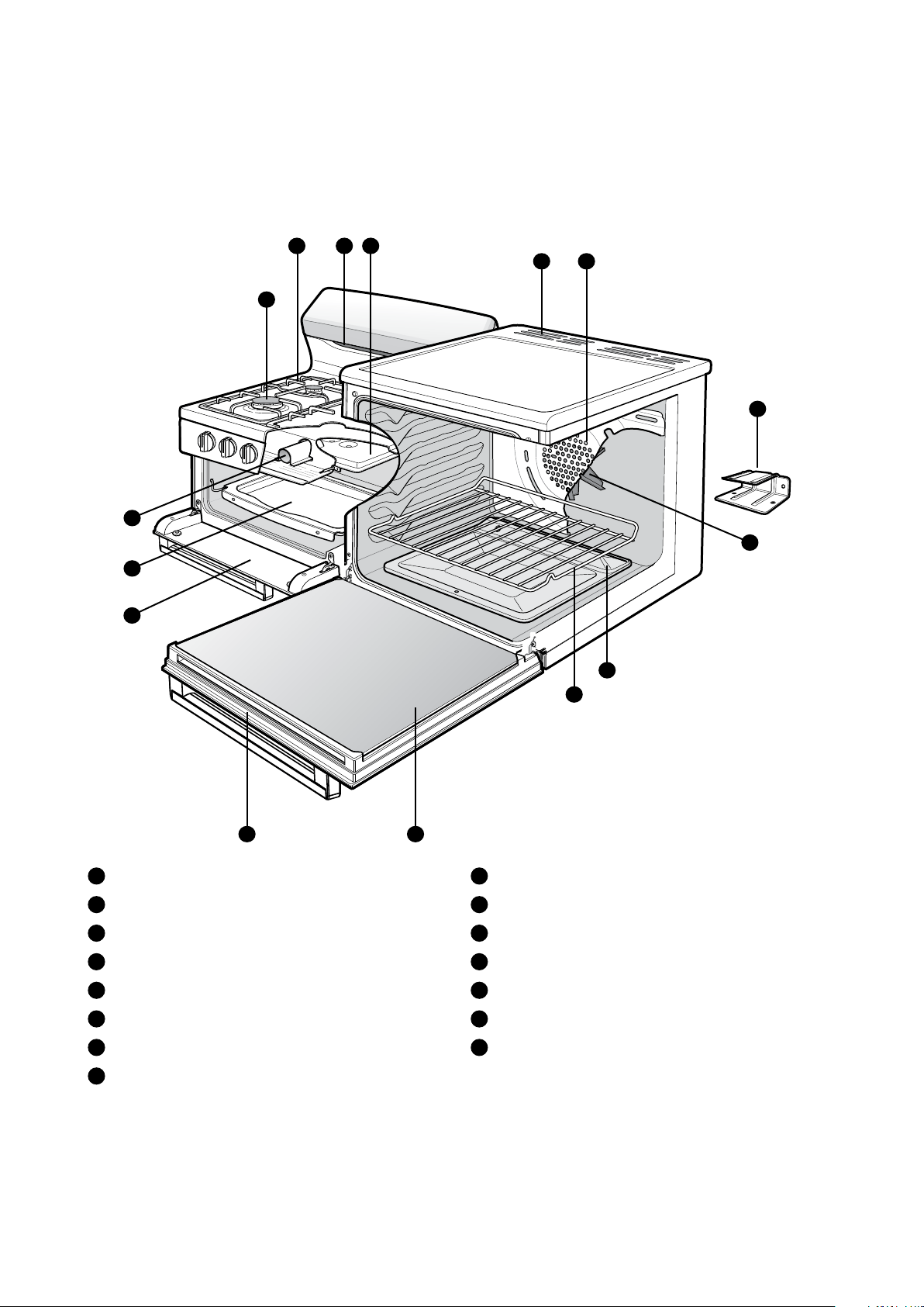
GENERAL APPLIANCE DESCRIPTION – GAS ELEVATED
(R.H VARIANT SHOWN)
1
Grill Door
2
Removable Grill Dish
3
Grill Burner Reflector
4
Removable Hotplate Burner
5
Removable Trivet
6
Grill Vent
7
Grill Burner
8
Oven Vent
9
Fan Cover
10
Anti-tilt Plate
11
Oven Fan
12
Oven Burner Cover
13
Removable Shelf
14
Removable Inner Glass
15
Oven Door
4
5 6
8 9
10
14
13
12
11
2
3
1
7
15
PRODUCT DESCRIPTION INSTALLING THE ELECTRIC ELEVATED COOKER
INSTALLING THE ELECTRIC ELEVATED COOKER
Safety Warnings about installation
WARNING
WARNING
• The cooker MUST be installed and serviced by a
qualified technician.
• A Certificate of Compliance MUST be supplied to be
kept by the customer.
• The packing materials MUST be removed before you
install the cooker.
• You MUST follow the installation instructions in this
booklet.
• In order to avoid overheating, the cooker must not
be installed behind ta decorative door.
• The surrounding kitchen cabinets MUST be able
to withstand 85°C. Electrolux Products WILL
NOT accept responsibility for damage caused by
installation into kitchen cabinets which cannot
withstand 85°C.
• In order to avoid overheating of the cooker,
the cooker must not be installed behind a
decorative door
• The appliance MUST be installed using the flexible
hose supplied.
• The vents, openings and air spaces MUST NOT
be blocked.
• You MUST NOT pull the cooker by the door handles
or the splashback.
• The cooker MUST be checked every five years.
• The cooker MUST NOT be used as a space heater.
Locating the cooker
Study the diagrams below to be sure of the dimensions
required to locate the cooker safely.
Wiring connection
postion
320
1085
544
900
600
Locating V
1095 Minimum
740 L.H. Oven
200 R.H. Oven
620
300 Maximum
Dimension to centre
line of anti-tilt plate
60
762
WARNING
WARNING
In order to avoid accidental tipping of the appliance
(for example, by a child climbing onto the open oven
door), the anti-tilt plate MUST be installed.
Position the anti-tilt plate to the rear wall and 762mm
from the left side of the wall. Dimension to the “v”
at the front of the anti-tilt plate and then securely fix
-with fasteners.
The following table outlines the distance between the
floor supporting the product and the surface supporting
cooking vessel;
Surface type
(Supporting vessel)
Distance (MM)
Solid Hob 321
Enamel Trivets 327
Ceramic Glass 305
Loading ...
Loading ...
Loading ...