Loading ...
Loading ...
Loading ...
Owner’s Manual for Portable Generator 7
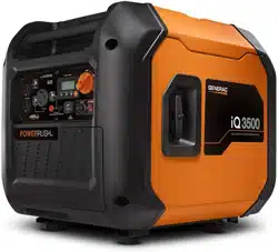
Generator Status Lights
See Figure 2-7.
• Overload LED (red): Indicates system
overload (2). During motor starting it is nor-
mal for the overload LED to illuminate for a
few seconds. If LED stays illuminated and
the ready LED turns off, the engine will con-
tinue to run without output power. Remove
all applied loads and determine if attached
devices exceed recommended output
power. Check for faulty or shorted connec-
tions. To restore electrical output, turn dial
OFF to reset. Start engine. If condition was
corrected, the orange LED will not illumi-
nate and electrical output will be restored.
Loads can be applied once the green LED
illuminates. If the orange LED returns, con-
tact an IASD.
• Low Oil Level LED (yellow): Illuminates
when oil level is below safe operating level.
Engine shuts down (1).
• Power LED (green): Indicates output from
generator (3) (unless there is a low oil or
overload condition).
Figure 2-7. Status Indicators
Circuit Protectors
The AC receptacles are protected by an AC
circuit protector. If the generator is overloaded
or an external short circuit occurs, the circuit
protector will trip. If this occurs, disconnect all
electrical loads to determine the cause of the
problem before using the generator again.
Reduce the load if the circuit protector is
tripped.
NOTE: Continuous tripping of the circuit pro-
tector may cause damage to generator or
equipment.
Push the button of the protector to reset the
circuit protector.
Remove Contents from Carton
1. Open carton completely by cutting each
corner from top to bottom.
2. Remove and verify carton contents prior to
assembly. Carton contents should contain
the following:
TABLE 3. Accessories
3. Call Generac Customer Service at 1-888-
GENERAC (1-888-436-3722) with the unit
model and serial number for any missing
carton contents.
4. Record model, serial number, and date of
purchase on front cover of this manual.
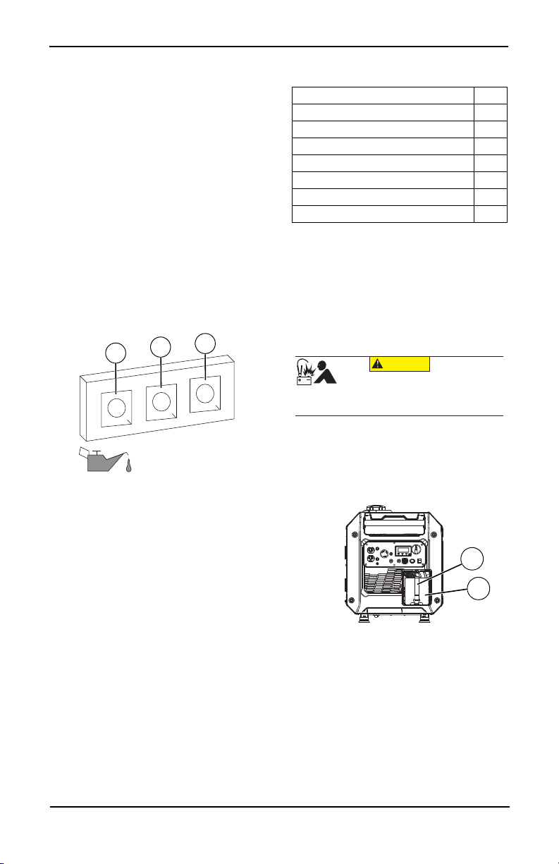
Battery Cable Connection (if
equipped)
The unit has been shipped with the battery
cables disconnected.
See Figure 2-7.
1. Use a Phillips screwdriver to remove the
screw from the battery door.
2. Remove battery strap (1) from battery (2).
Figure 2-8. Battery Connection
3. First, connect the red cables to the positive
(+) battery terminal with the bolt and nut
supplied.
4. Make sure connections are secure and
slide rubber boot over the positive (+) bat-
tery terminal and connection hardware.
5. Connect the black cables to the negative
(-) battery terminal with the bolt and nut
supplied. Slide rubber boot over the neg-
ative (-) battery terminal and connection
hardware.
6. Make sure all connections are secure.
OVERLOAD OUT
PU
T
1
2
3
005483
Item Qty.
Main Unit 1
Owner’s Manual 1
Engine Oil 1
Oil Funnel 1
Tool Kit 1
Service Warranty 1
Emissions Warranty 1
(000167a)
CAUTION
Equipment damage. Do not make battery
connections in reverse. Doing so will result
in equipment damage.
OUTPUT
FAULT
007843
2
1
Loading ...
Loading ...
Loading ...