
kkiiaa,,
tthhee
ccoommppaannyy
Thank you for becoming the owner of a new Kia vehicle.
As a global car manufacturing company focused on building high-
quality vehicles at value prices, Kia Motors is dedicated to providing you
with Service above your expectation and delight customer experience.
In our Kia dealerships you will experience our “Family-like Care”
promise, that creates feelings of warmth, hospitality and trust –
feelings of being looked after by people who care.
All information contained in this Owner’s Manual was accurate at the
time of publication. However, Kia reserves the right to make changes
at any time so that our policy of continual product improvement can be
carried out.
This manual applies to all Kia models and includes descriptions and
explanations of optional as well as standard equipment. As a result, you
may encounter material in this manual that is not applicable to your
specific Kia vehicle.
Enjoy your vehicle & experience Kia “Family-like Care” !

i
Thank you for choosing a Kia vehicle.
This manual will familiarize you with operational, maintenance and safety information about your new vehicle. It is
supplemented by a Warranty and Maintenance book that provides important information on all warranties regarding
your vehicle. Kia urges you to read these publications carefully and follow the recommendations to help assure
enjoyable and safe operation of your new vehicle.
Kia offers a great variety of options, components and features for its various models. Therefore, some of the equip-
ment described in this manual, along with the various illustrations, may not be applicable to your particular vehicle.
The information and specifications provided in this manual were accurate at the time of printing. Kia reserves the
right to discontinue or change specifications or design at any time without notice and without incurring any obliga-
tion. If you have questions, we recommend to contact your authorized Kia dealer.
Kia assures you of our continuing interest in your motoring pleasure and satisfaction in your Kia vehicle.
© 2017 Kia Motors Slovakia s.r.o.
All rights reserved. Reproduction by any means, electronic or mechanical, including photocopying, recording, or by
any information storage and retrieval system or translation in whole or part is not permitted without written author-
ization from Kia Motors Slovakia s.r.o..
FFoorreewwoorrdd

ii
1
2
3
4
5
6
7
8
I
Introduction
Your vehicle at a glance
Safety features of your vehicle
Features of your vehicle
Driving your vehicle
What to do in an emergency
Maintenance
Specifications & Consumer information
Index
table of contents

Introduction
How to use this manual . . . . . . . . . . . . . . . . . . . . . . 1-2
Fuel requirements . . . . . . . . . . . . . . . . . . . . . . . . . . 1-2
• Gasoline engine. . . . . . . . . . . . . . . . . . . . . . . . . . . . . . . 1-2
• Diesel engine . . . . . . . . . . . . . . . . . . . . . . . . . . . . . . . . . 1-4
Vehicle break-in process . . . . . . . . . . . . . . . . . . . . . 1-5
1
Introduction
21
We want to help you get the greatest
possible driving pleasure from your vehi-
cle. Your Owner’s Manual can assist you
in many ways. We strongly recommend
that you read the entire manual. In order
to minimize the chance of death or injury,
you must read the WARNING and CAU-
TION sections in the manual.
Illustrations complement the words in this
manual to best explain how to enjoy your
vehicle. By reading your manual, you will
learn about features, important safety
information, and driving tips under vari-
ous road conditions.
The general layout of the manual is pro-
vided in the Table of Contents. Use the
index when looking for a specific area or
subject; it has an alphabetical listing of all
information in your manual.
Sections: This manual has eight sections
plus an index. Each section begins with a
brief list of contents so you can tell at a
glance if that section has the information
you want.
You will find various WARNINGS, CAU-
TIONS, and NOTICES in this manual.
These were prepared to enhance your
personal safety.You should carefully read
and follow ALL procedures and recom-
mendations provided in these WARN-
INGS, CAUTIONS and NOTICES.
✽✽
NOTICE
A NOTICE indicates interesting or help-
ful information is being provided.
Gasoline engine
Unleaded
For Europe
For the optimal vehicle performance, we
recommend you to use unleaded gaso-
line with an octane rating of RON
(Research Octane Number) 95 / AKI (Anti
Knock Index) 91 or higher (Do not use
methanol blended fuels). You may use
unleaded gasoline with an octane rating
of RON 91-94 / AKI 87-90 but it may
result in slight performance reduction of
the vehicle.
Except Europe
Your new vehicle is designed to use only
unleaded fuel having an Octane Rating
of RON (Research Octane Number) 91 /
AKI (Anti-Knock Index) 87 or higher. (Do
not use methanol blended fuels)
Your new vehicle is designed to obtain
maximum performance with UNLEADED
FUEL, as well as minimize exhaust emis-
sions and spark plug fouling.
HOW TO USE THIS MANUAL
WARNING
A WARNING indicates a situation in
which harm, serious bodily injury or
death could result if the warning is
ignored.
CAUTION
A CAUTION indicates a situation in
which damage to your vehicle could
result if the caution is ignored.
FUEL REQUIREMENTS
13
Introduction
Gasoline containing alcohol and
methanol
Gasohol, a mixture of gasoline and
ethanol (also known as grain alcohol),
and gasoline or gasohol containing
methanol (also known as wood alcohol)
are being marketed along with or instead
of leaded or unleaded gasoline.
Do not use gasohol containing more than
10% ethanol, and do not use gasoline or
gasohol containing any methanol. Either
of these fuels may cause drivability prob-
lems and damage to the fuel system,
engine control system and emission con-
trol system.
Discontinue using gasohol of any kind if
drivability problems occur.
Vehicle damage or driveability problems
may not be covered by the manufacturer’s
warranty if they result from the use of:
1. Gasohol containing more than 10%
ethanol.
2. Gasoline or gasohol containing
methanol.
3. Leaded fuel or leaded gasohol.
Other fuels
Using fuels such as
- Silicone (Si) contained fuel,
- MMT (Manganese, Mn) contained fuel,
- Ferrocene (Fe) contained fuel, and
- Other metalic additives contained fuels,
may cause vehicle and engine damage or
cause plugging, misfiring, poor accelera-
tion, engine stalling, catalyst melting,
abnormal corrosion, life cycle reduction,
etc.
Also, the Malfunction Indicator Lamp
(MIL) may illuminate.
✽✽
NOTICE
Damage to the fuel system or perform-
ance problem caused by the use of these
fuels may not be covered by your New
Vehicle Limited Warranty.
CAUTION
NEVER USE LEADED FUEL. The
use of leaded fuel is detrimental to
the catalytic converter and will
damage the engine control sys-
tem’s oxygen sensor and affect
emission control.
Never add any fuel system cleaning
agents to the fuel tank other than
what has been specified. We recom-
mend that the system be checked
by an authorized Kia dealer.
WARNING
• Do not "top off" after the nozzle
automatically shuts off when
refueling.
• Always check that the fuel cap is
installed securely to prevent fuel
spillage in the event of an acci-
dent.
CAUTION
Never use gasohol which contains
methanol. Discontinue use of any
gasohol product which impairs dri-
vability.

Introduction
41
Use of MTBE
Kia recommends avoiding fuels contain-
ing MTBE (Methyl Tertiary Butyl Ether)
over 15.0% vol. (Oxygen Content 2.7%
weight) in your vehicle.
Fuel containing MTBE over 15.0% vol.
(Oxygen Content 2.7% weight) may
reduce vehicle performance and produce
vapor lock or hard starting.
Do not use methanol
Fuels containing methanol (wood alco-
hol) should not be used in your vehicle.
This type of fuel can reduce vehicle per-
formance and damage components of
the fuel system, engine control system
and emission control system.
Fuel Additives
Kia recommends that you use unleaded
gasoline which has an octane rating of
RON (Research Octane Number) 95 / AKI
(Anti Knock Index) 91 or higher (for
Europe) or Octane Rating of RON
(Research Octane Number) 91 / AKI (Anti-
Knock Index) 87 or higher (except Europe).
For customers who do not use good
quality gasolines including fuel additives
regularly, and have problems starting or
the engine does not run smoothly, one
bottle of additives added to the fuel tank
at every 15,000km (for Europe)/ 5,000km
(except Europe). Additives are available
from your authorized Kia dealer along
with information on how to use them. Do
not mix other additives.
Operation in foreign countries
If you are going to drive your vehicle in
another country, be sure to:
• Observe all regulations regarding reg-
istration and insurance.
• Determine that acceptable fuel is avail-
able.
Diesel engine
Diesel fuel
Diesel engine must be operated only on
commercially available diesel fuel that
complies with EN 590 or comparable
standard. (EN stands for "European
Norm"). Do not use marine diesel fuel,
heating oils, or non-approved fuel addi-
tives, as this will increase wear and
cause damage to the engine and fuel
system. The use of non-approved fuels
and / or fuel additives will result in a limi-
tation of your warranty rights.
Diesel fuel of above cetane 51 is used in
your vehicle. If two types of diesel fuel
are available, use summer or winter fuel
properly according to the following tem-
perature conditions.
• Above -5°C (23°F) ... Summer type
diesel fuel.
• Below -5°C (23°F) ... Winter type diesel
fuel.
Watch the fuel level in the tank very care-
fully : If the engine stops through fuel fail-
ure, the circuits must be completely
purged to permit restarting.
CAUTION
Your New Vehicle Limited Warranty
may not cover damage to the fuel
system and any performance prob-
lems that are caused by the use of
fuels containing methanol or fuels
containing MTBE (Methyl Tertiary
Butyl Ether) over 15.0% vol.
(Oxygen Content 2.7% weight.)
15
Introduction
Biodiesel
Commercially supplied Diesel blends of
no more than 7% biodiesel, commonly
known as "B7 Diesel" may be used in
your vehicle if Biodiesel meets EN 14214
or equivalent specifications. (EN stands
for "European Norm"). The use of biofu-
els exceeding 7% made from rapeseed
methyl ester (RME), fatty acid methyl
ester (FAME), vegetable oil methyl ester
(VME) etc. or mixing diesel exceeding
7% with biodiesel will cause increased
wear or damage to the engine and fuel
system. Repair or replacement of worn or
damaged components due to the use of
non approved fuels will not be covered by
the manufactures warranty.
No special break-in period is needed. By
following a few simple precautions for the
first 1,000 km (600 miles) you may add to
the performance, economy and life of
your vehicle.
• Do not race the engine.
• While driving, keep your engine speed
(rpm, or revolutions per minute)
between 2,000 rpm and 4,000 rpm.
• Do not maintain a single speed for long
periods of time, either fast or slow.
Varying engine speed is needed to
properly break-in the engine.
• Avoid hard stops, except in emergen-
cies, to allow the brakes to seat prop-
erly.
• Don't tow a trailer during the first 2,000
km (1,200 miles) of operation.
CAUTION
Do not let any gasoline or water
enter the tank. This would make it
necessary to drain it out and to
bleed the lines to avoid jamming the
injection pump and damaging the
engine.
CAUTION - Diesel Fuel
(if equipped with DPF)
It is recommended to use the regu-
lated automotive diesel fuel for
diesel vehicle equipped with the
DPF system.
If you use diesel fuel including high
sulfur (more than 50 ppm sulfur) and
unspecified additives, it can cause
the DPF system to be damaged and
white smoke can be emitted.
CAUTION
• Never use any fuel, whether
diesel, B7 biodiesel or otherwise,
that fails to meet the latest petro-
leum industry specification.
• Never use any fuel additives or
treatments that are not recom-
mended or approved by the vehi-
cle manufacturer.
VEHICLE BREAK-IN PROCESS

Your vehicle at a glance
Exterior overview (front) . . . . . . . . . . . . . . . . . . . . 2-2
Exterior overview (rear) . . . . . . . . . . . . . . . . . . . . . 2-3
Interior overview . . . . . . . . . . . . . . . . . . . . . . . . . . . 2-4
Instrument panel overview . . . . . . . . . . . . . . . . . . . 2-5
Engine compartment . . . . . . . . . . . . . . . . . . . . . . . . 2-6
2
Your vehicle at a glance
22
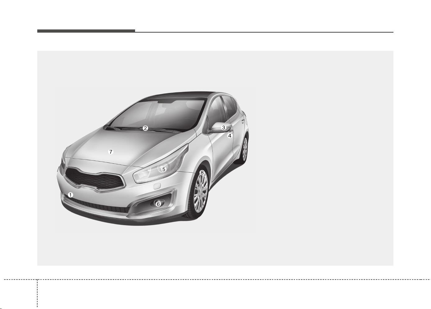
EXTERIOR OVERVIEW (FRONT)
1. Front removable towing hook .................6-37
2. Front windshield wiper..........................4-131
3. Outside rearview mirror ..........................4-45
4. Door lock ................................................4-17
5. Head lamp ...................................4-121, 7-81
6. Front fog lamp.......................................4-127
7. Hood ......................................................4-29
8. Tire and wheel ........................................7-45
OJD015001
❈ The actual shape may differ from the illustration.
23
Your vehicle at a glance
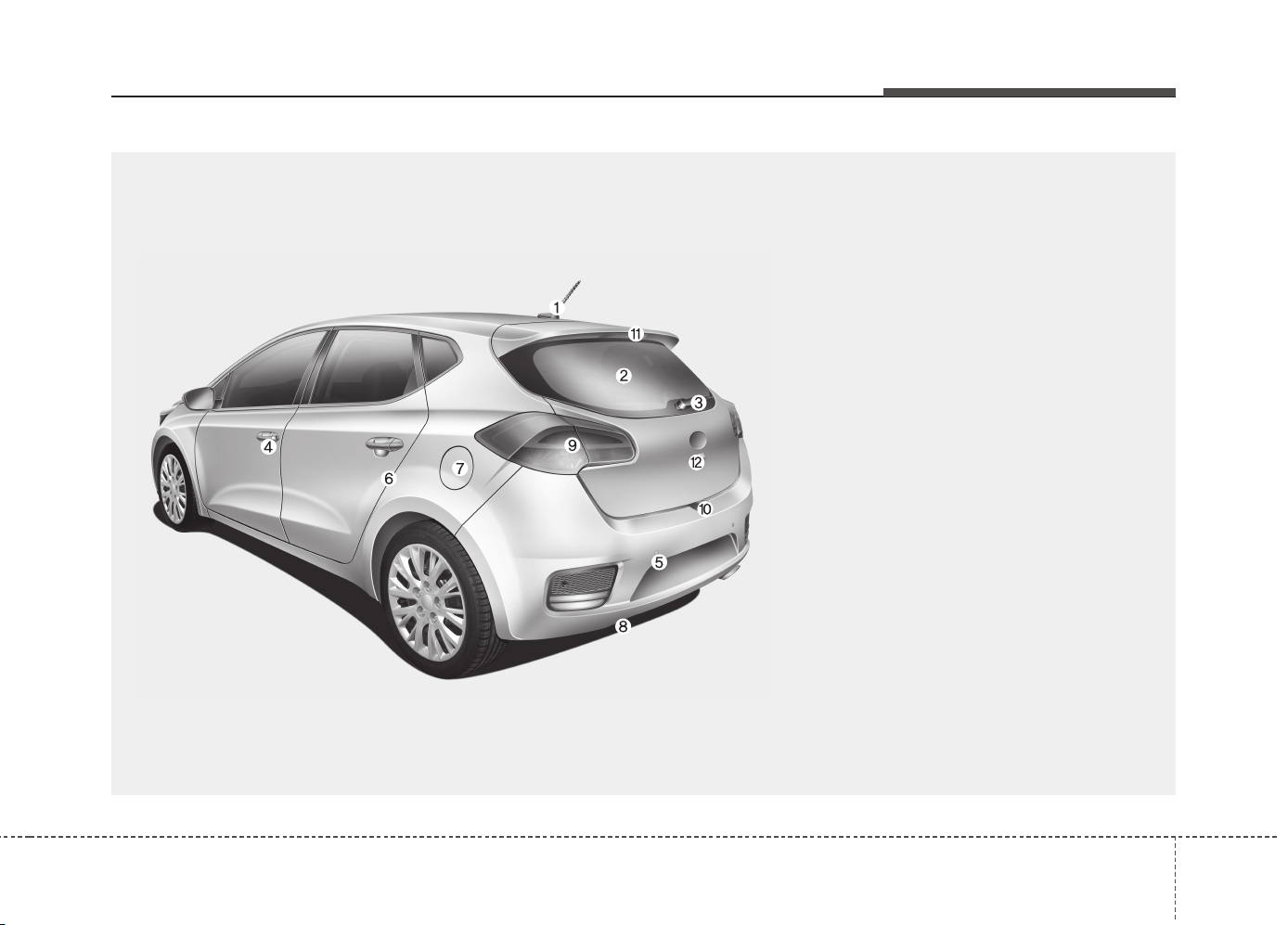
EXTERIOR OVERVIEW (REAR)
1. Roof antenna ........................................4-185
2. Rear window defroster..........................4-139
3. Rear wiper ............................................4-134
4. Door lock ................................................4-17
5. Rear parking assist system ....................4-95
6. Child-protector rear door lock.................4-21
7. Fuel filler lid ............................................4-31
8. Rear towing hook....................................6-37
9. Rear combination lamp ..........................7-93
10. Tailgate handle switch .........................4-22
11. High mounted stop lamp ......................7-98
12. Rearview camera................................4-120
OJD015002
❈ The actual shape may differ from the illustration.
Your vehicle at a glance
42
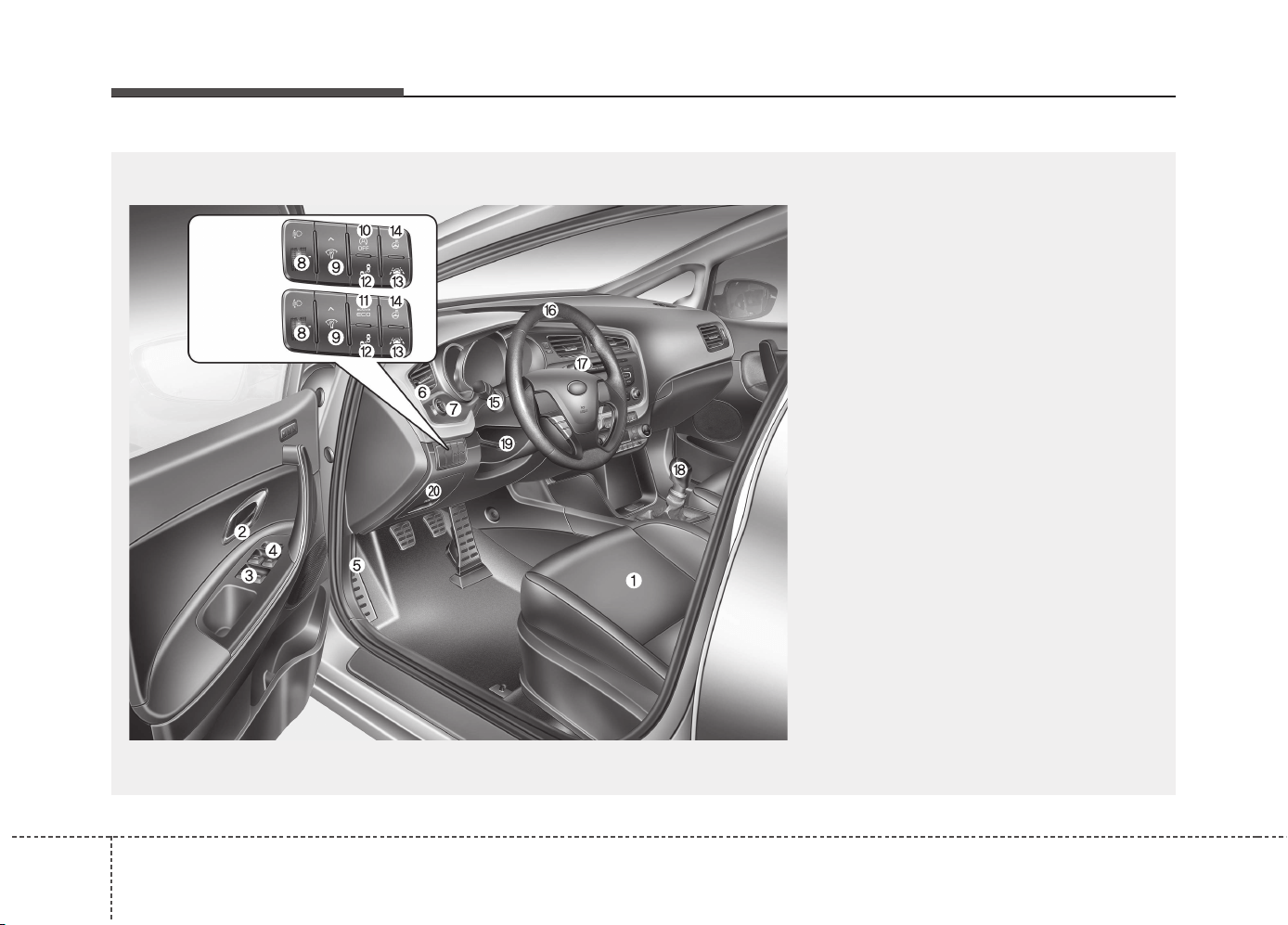
INTERIOR OVERVIEW
1. Seat..........................................................3-2
2. Inside door handle ................................4-18
3. Power window switch ............................4-24
4. Power window lock button......................4-27
5. Hood release lever ................................4-29
6. Outside rearview mirror folding..............4-46
7. Outside rearview mirror control..............4-46
8. Headlight leveling device ....................4-128
9. Instrument panel illumination control
system ..........................................4-49, 4-63
10. Idle Stop and Go (ISG) OFF button ....5-15
11. Active ECO button ..............................5-39
12. Blind spot detection system
ON/OFF button ....................................5-74
13. Lane departure warning system
ON/OFF button ......................................5-66
14. Heated steering wheel button..............4-40
15. Light control/Turn signals ..................4-122
16. Steering wheel ....................................4-39
17. Wiper/Washer ....................................4-131
18. Transaxle shift lever ..........5-20, 5-23, 5-30
19. Tilt and telescopic steering
control lever ..............................................4-40
20. Fuse box ..............................................7-56
OJD015003
❈ The actual shape may differ from the illustration.
■ Type A
■ Type B
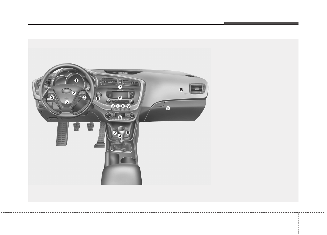
INSTRUMENT PANEL OVERVIEW
OJD012004
25
Your vehicle at a glance
❈ The actual shape may differ from the illustration.
1. Instrument cluster .....................4-48, 4-61
2. Horn ...................................................4-41
3. Steering wheel audio control............4-186
4. Cruise control switch ..........................5-59
Speed limiter control switch ...............5-63
Cluster display mode conversion
switch .................................................4-63
5. Driver’s air bag ...................................3-51
6. Ignition switch or
ENGINE START/STOP button ......5-5, 5-9
7. Hazard warning switch .....................4-120
8. Audio ................................................4-199
9. Seat warmer.......................................3-12
10. Central door lock switch ...................4-19
11. ESC OFF button...............................5-51
12. Climate control system .......4-140, 4-149
13. Cigar lighter....................................4-168
14. Aux, USB and iPod port .................4-187
15. Power outlet ...................................4-172
16. Front passenger’s air bag ................3-51
17. Glove box .......................................4-165
Your vehicle at a glance
62
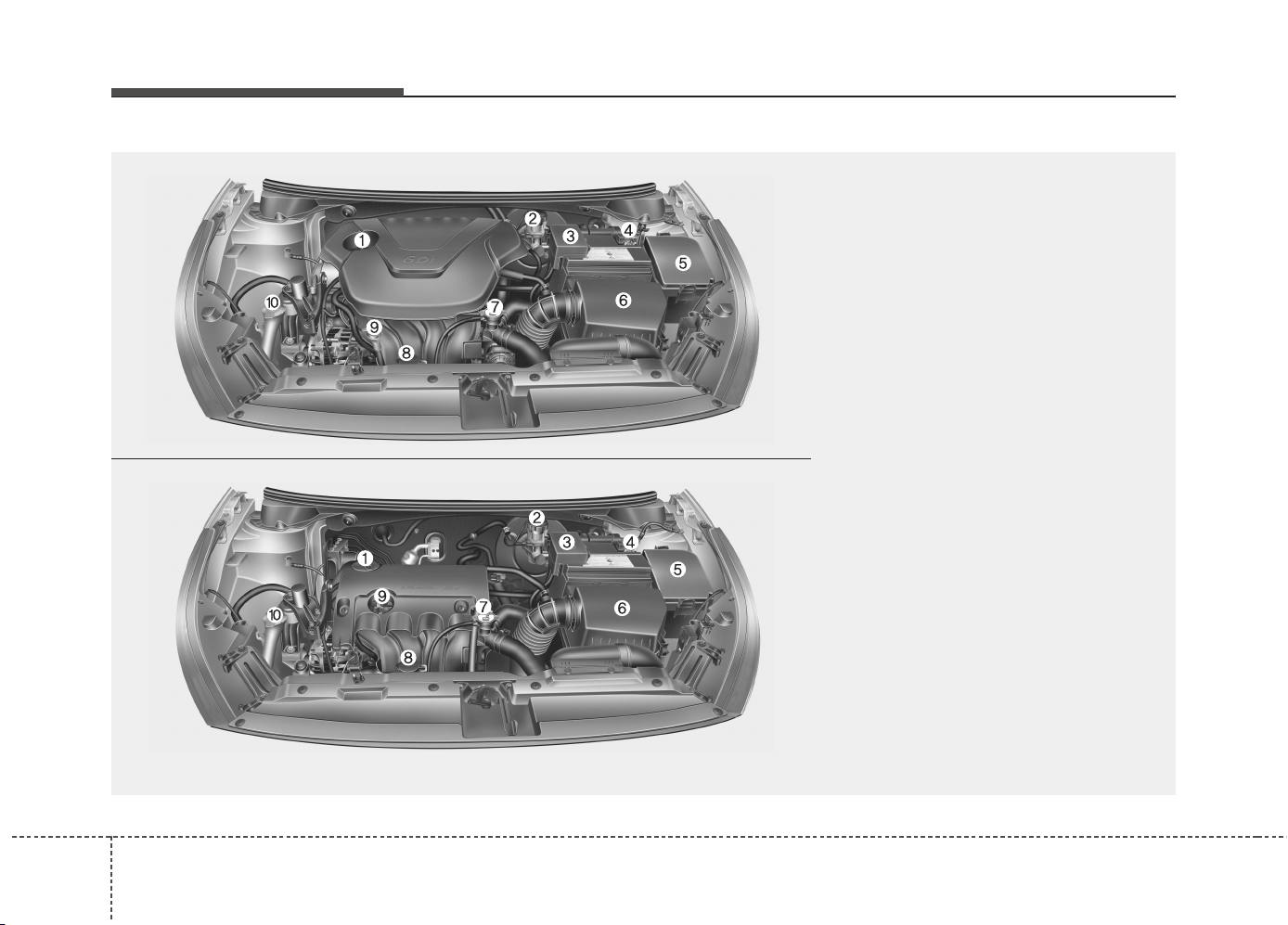
ENGINE COMPARTMENT
OJD072001/OJD072002
❈ The actual engine room in the vehicle may differ from the illustration.
1. Engine oil filler cap ............................7-28
2. Brake/clutch fluid reservoir ................7-32
3. Positive battery terminal ....................7-42
4. Negative battery terminal ..................7-42
5. Fuse box............................................7-56
6. Air cleaner ........................................7-35
7. Radiator cap ......................................7-31
8. Engine coolant reservoir....................7-29
9. Engine oil dipstick..............................7-27
10. Windshield washer fluid reservoir....7-33
■■
Gasoline engine (GDI)
■■
Gasoline engine (MPI)
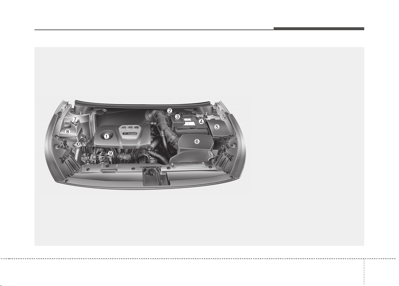
27
Your vehicle at a glance
1. Engine oil filler cap ............................7-28
2. Brake/clutch fluid reservoir ................7-32
3. Positive battery terminal ....................7-42
4. Negative battery terminal ..................7-42
5. Fuse box............................................7-56
6. Air cleaner ........................................7-35
7. Radiator cap ......................................7-31
8. Engine coolant reservoir....................7-29
9. Engine oil dipstick..............................7-27
10. Windshield washer fluid reservoir....7-33
OJD075106L
❈ The actual engine room in the vehicle may differ from the illustration.
■
■
Gasoline engine (Gamma 1.6 T-GDI)
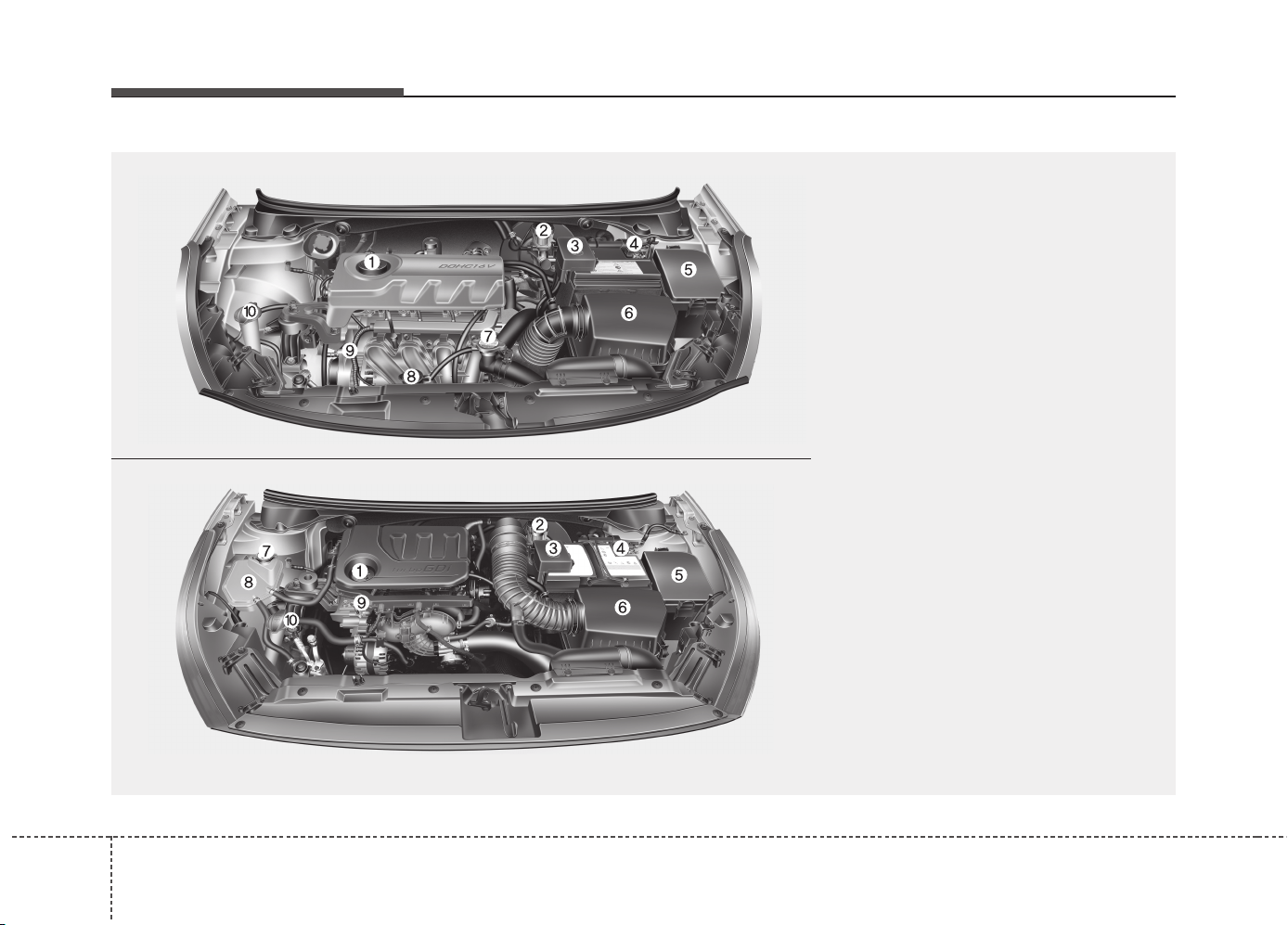
Your vehicle at a glance
82
OGD075001/OJD075100L
❈ The actual engine room in the vehicle may differ from the illustration.
1. Engine oil filler cap ............................7-28
2. Brake/clutch fluid reservoir ................7-32
3. Positive battery terminal ....................7-42
4. Negative battery terminal ..................7-42
5. Fuse box............................................7-56
6. Air cleaner ........................................7-35
7. Radiator cap ......................................7-31
8. Engine coolant reservoir....................7-29
9. Engine oil dipstick..............................7-27
10. Windshield washer fluid reservoir....7-33
■■
Gasoline Engine (Kappa 1.4 MPI)
■■
Gasoline Engine (Kappa 1.0 T-GDI)
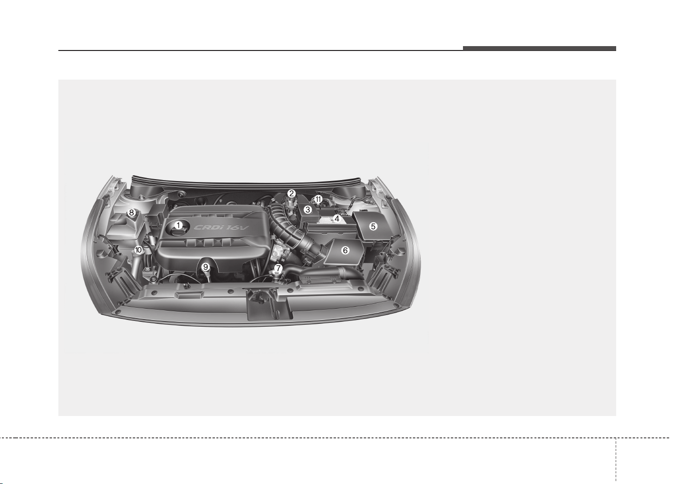
29
Your vehicle at a glance
OJD075101L
❈ The actual engine room in the vehicle may differ from the illustration.
1. Engine oil filler cap ............................7-28
2. Brake/clutch fluid reservoir ................7-32
3. Positive battery terminal ....................7-42
4. Negative battery terminal ..................7-42
5. Fuse box............................................7-56
6. Air cleaner ........................................7-35
7. Radiator cap ......................................7-31
8. Engine coolant reservoir....................7-29
9. Engine oil dipstick..............................7-27
10. Windshield washer fluid reservoir....7-33
11. Fuel filter ........................................7-34
■■
Diesel engine (UII)

Safety features of your vehicle
Seat . . . . . . . . . . . . . . . . . . . . . . . . . . . . . . . . . . . . . . 3-2
• Front seat . . . . . . . . . . . . . . . . . . . . . . . . . . . . . . . . . . . 3-4
• Driver position memory system . . . . . . . . . . . . . . . . . . 3-8
• Rear seat . . . . . . . . . . . . . . . . . . . . . . . . . . . . . . . . . . . 3-14
Seat belts . . . . . . . . . . . . . . . . . . . . . . . . . . . . . . . . . 3-20
• Seat belt restraint system . . . . . . . . . . . . . . . . . . . . . . 3-20
• Pre-tensioner seat belt . . . . . . . . . . . . . . . . . . . . . . . . 3-26
• Seat belt precautions . . . . . . . . . . . . . . . . . . . . . . . . . . 3-28
• Care of seat belts . . . . . . . . . . . . . . . . . . . . . . . . . . . . . 3-31
Child restraint system . . . . . . . . . . . . . . . . . . . . . . 3-32
• Using a child restraint system . . . . . . . . . . . . . . . . . . 3-34
Air bag - supplemental restraint system . . . . . . . 3-43
• How does the air bag system operate . . . . . . . . . . . . 3-44
• Air bag warning and indicator . . . . . . . . . . . . . . . . . 3-46
• SRS components and functions . . . . . . . . . . . . . . . . . 3-48
• Driver's and passenger's front air bag . . . . . . . . . . . 3-51
• Side impact air bag . . . . . . . . . . . . . . . . . . . . . . . . . . . 3-56
• Curtain air bag . . . . . . . . . . . . . . . . . . . . . . . . . . . . . . 3-57
• SRS Care . . . . . . . . . . . . . . . . . . . . . . . . . . . . . . . . . . . 3-64
• Additional safety precautions. . . . . . . . . . . . . . . . . . . 3-65
• Air bag warning label . . . . . . . . . . . . . . . . . . . . . . . . . 3-66
3
JD PE eng 3.QXP 03.01.2017 16:37 Page 1
Safety features of your vehicle
23
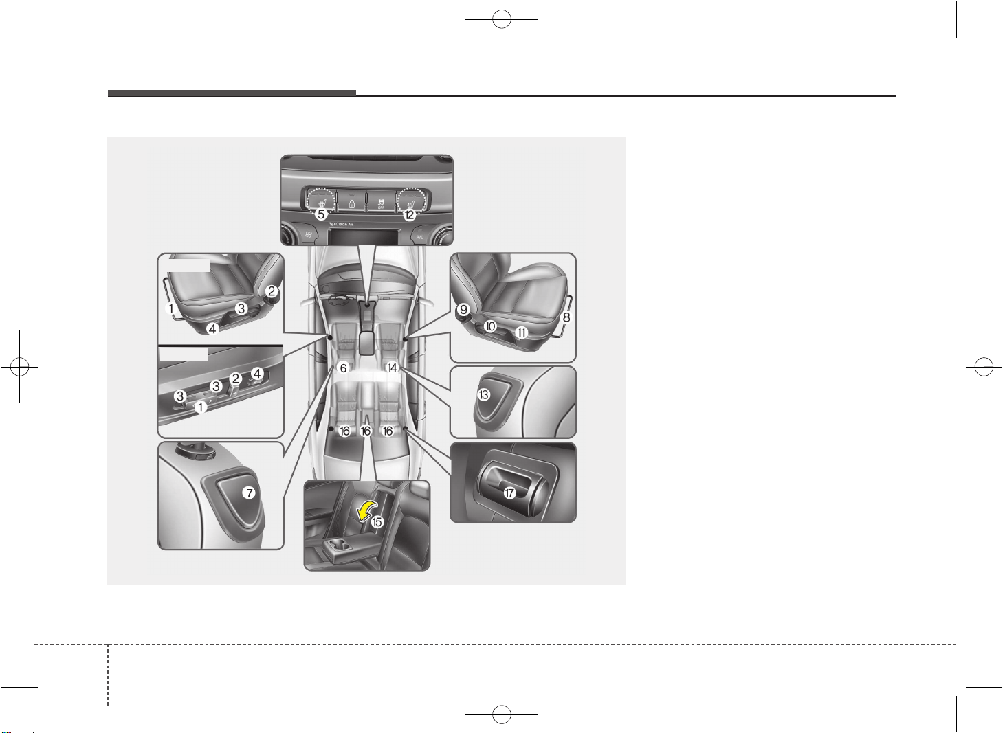
Driver’s seat
(1) Seat adjustment, forward/backward
(2) Seatback recliner
(3) Seat adjustment, height
(4) Lumber support*
(5) Seat warmer*
(6) Headrest adjustment
(7) Walk-in seat
(for 3 door vehicle only)
Front passenger seat
(8) Seat adjustment, forward/backward
(9) Seatback recliner
(10) Seat adjustment, height*
(11) Lumber support*
(12) Seat warmer*
(13) Walk-in seat
(for 3 door vehicle only)
(14) Headrest adjustment
Rear seat
(15) Armrest*
(16) Headrest adjustment
(17) Split folding rear seat
* : if equipped
SEAT
OJD033001
■ Type A
■ Type B
JD PE eng 3.QXP 03.01.2017 16:37 Page 2
33
Safety features of your vehicle
✽✽
NOTICE
If you have a collision accident, the front
seat may be damaged.
In this case we recommend that you
have a seat system checked by an
authorized Kia dealer.
WARNING - Driver’s seat
• Never attempt to adjust seat
while the vehicle is moving. This
could result in loss of control,
and an accident causing death,
serious injury, or property dam-
age.
• Do not allow anything to interfere
with the normal position of the
seatback. Storing items against a
seatback or in any other way
interfering with proper locking of
a seatback could result in serious
or fatal injury in a sudden stop or
collision.
• Always drive and ride with your
seatback upright and the lap por-
tion of the seat belt snug and low
across the hips. This is the best
position to protect you in case of
an accident.
• In order to avoid unnecessary
and perhaps severe air bag
injuries, always sit as far back as
possible from the steering wheel
while maintaining comfortable
control of the vehicle. It is recom-
mended that your chest is at least
250 mm (10 inches) away from
the steering wheel.
WARNING - Loose objects
Loose objects in the driver’s foot
area could interfere with the opera-
tion of the foot pedals, possibly
causing an accident. Do not place
anything under the front seats.
WARNING - Driver respon-
sibility for front seat pas-
senger
Riding in a vehicle with a front seat-
back reclined could lead to serious
or fatal injury in an accident. If a
front seat is reclined during an
accident, the occupant’s hips may
slide under the lap portion of the
seat belt applying great force to the
unprotected abdomen. Serious or
fatal internal injuries could result.
The driver must advise the front
passenger to keep the seatback in
an upright position whenever the
vehicle is in motion.
WARNING
Do not use a sitting cushion that
reduces friction between the seat
and passenger. The passenger's
hips may slide under the lap por-
tion of the seat belt during an acci-
dent or a sudden stop. Serious or
fatal internal injuries could result
because the seat belt can't operate
normally.
JD PE eng 3.QXP 03.01.2017 16:37 Page 3
Safety features of your vehicle
43
WARNING - Rear seatbacks
• The rear seatback must be
securely latched. If not, passen-
gers and objects could be thrown
forward resulting in serious
injury or death in the event of a
sudden stop or collision.
• Luggage and other cargo should
be laid flat in the cargo area. If
objects are large, heavy, or must
be piled, they must be secured.
Under no circumstances should
cargo be piled higher than the
seatbacks. Failure to follow these
warnings could result in serious
injury or death in the event of a
sudden stop, collision or rollover.
• No passenger should ride in the
cargo area or sit or lie on folded
seatbacks while the vehicle is
moving. All passengers must be
properly seated in seats and
restrained properly while riding.
(Continued)
WARNING
After adjusting the seat, always
check that it is securely locked into
place by attempting to move the
seat forward or backward without
using the lock release lever.
Sudden or unexpected movement
of the driver's seat could cause you
to lose control of the vehicle result-
ing in an accident.
WARNING
• Use extreme caution so that
hands or other objects are not
caught in the seat mechanisms
while the seat is moving.
• Do not put a cigarette lighter on
the floor or seat. When you oper-
ate the seat, gas may gush out of
the lighter and cause fire.
• Use extreme caution when picking
small objects trapped under the
seats or between the seat and the
center console. Your hands might
be cut or injured by the sharp
edges of the seat mechanism.
(Continued)
• When resetting the seatback to
the upright position, make sure it
is securely latched by pushing it
forward and backwards.
• To avoid the possibility of burns,
do not remove the carpet in the
cargo area. Emission control
devices beneath this floor gener-
ate high temperatures.
JD PE eng 3.QXP 03.01.2017 16:38 Page 4
35
Safety features of your vehicle
Feature of Seat Leather
• Leather is made from the outer skin of
an animal, which goes through a spe-
cial process to be available for use.
Since it is a natural substance, each
part differs in thickness or density.
Wrinkles may appear as a natural
result of stretching and shrinking
depending on the temperature and
humidity.
• The seat is made of stretchable fabric
to improve comfort.
• The parts contacting the body are
curved and the side supporting area is
high which provides driving comfort
and stability.
• Wrinkles may appear naturally from
usage. It is not a fault of the product.
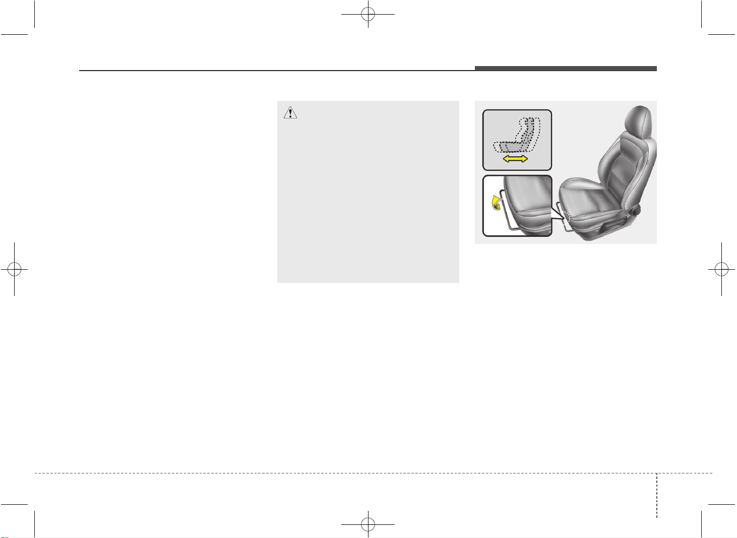
Front seat
Manual adjustment
Forward and backward
To move the seat forward or backward:
1. Pull the seat slide adjustment lever up
and hold it.
2. Slide the seat to the position you desire.
3. Release the lever and make sure the
seat is locked in place.
Adjust the seat before driving, and make
sure the seat is locked securely by trying
to move forward and backward without
using the lever. If the seat moves, it is not
locked properly.
OJD032002
CAUTION
• Wrinkles or abrasions which
appear naturally from usage are
not covered by warranty.
• Belts with metallic accessories,
zippers or keys inside the back
pocket may damage the seat fab-
ric.
• Make sure not to wet the seat. It
may change the nature of natural
leather.
• Jeans or clothes which could
bleach may contaminate the sur-
face of the seat covering fabric.
JD PE eng 3.QXP 03.01.2017 16:38 Page 5
Safety features of your vehicle
63
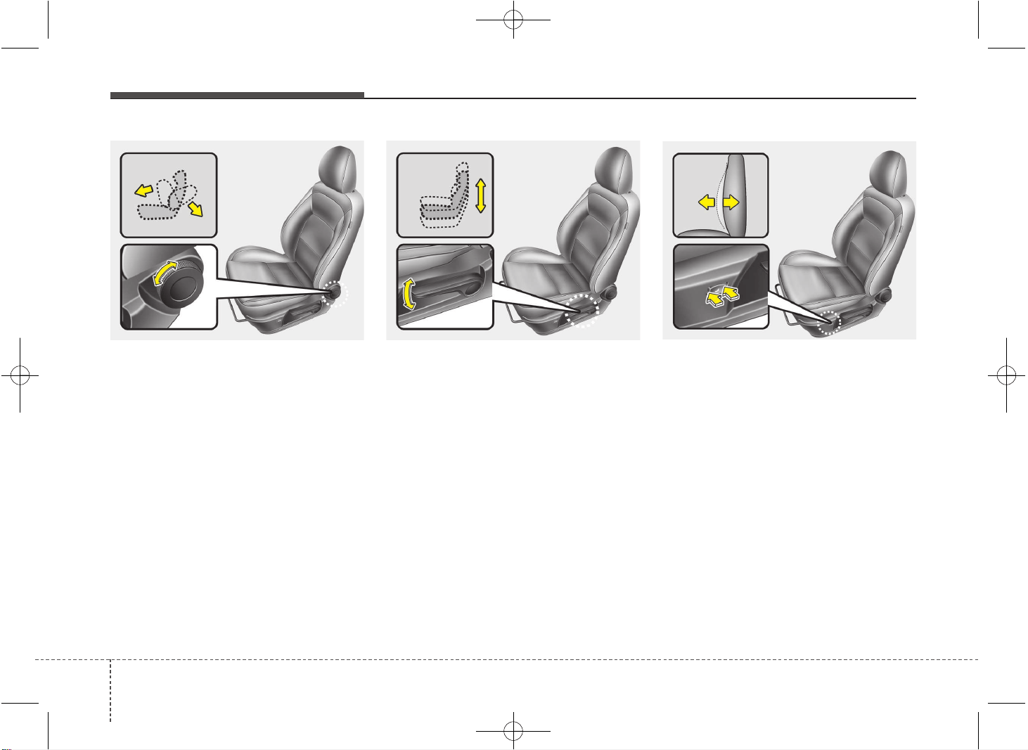
Seatback angle
Turn the control knob forward or rearward
to move the seatback to the desired
angle.
Seat cushion height (if equipped)
To change the height of the seat cushion,
push the lever upwards or downwards.
• To lower the seat cushion, push down
the lever several times.
• To raise the seat cushion, pull up the
lever several times.
Lumbar support (if equipped)
The lumbar support can be adjusted by
pressing the lumbar support switch on
the side of the seat.
1. Press the front portion of the switch to
increase support, or the rear portion of
the switch, to decrease support.
2. Release the switch once it reaches the
desired position.
OJD032004
OJD032055
OJD032003
JD PE eng 3.QXP 03.01.2017 16:38 Page 6
37
Safety features of your vehicle
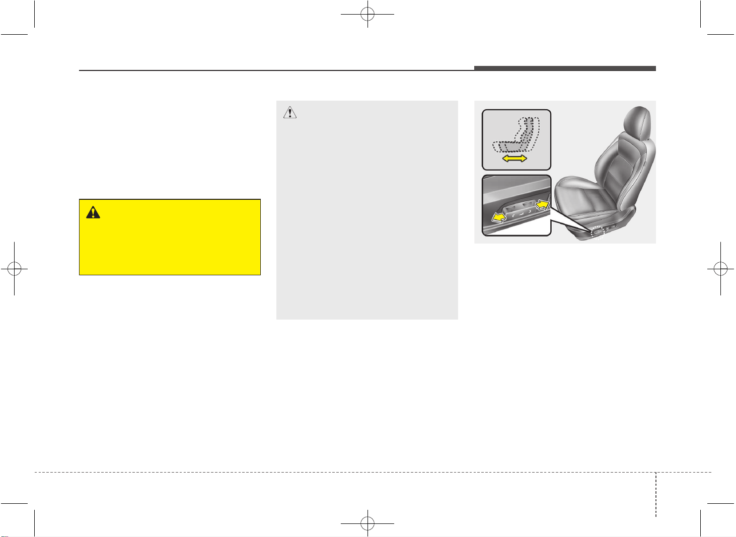
Automatic adjustment (if equipped)
The driver’s seat can be adjusted by
using the control switches located on the
outside of the seat cushion. Before driv-
ing, adjust the seat to the proper position
so as to easily control the steering wheel,
pedals and switches on the instrument
panel.
Forward and rearward
1. Push the control switch forward or
rearward to move the seat to the
desired position.
2. Release the switch once the seat
reaches the desired position.
CAUTION
• The power seat is driven by an
electric motor. Stop operating
once the adjustment is complet-
ed. Excessive operation may
damage the electrical equipment.
• When in operation, the power
seat consumes a large amount of
electrical power. To prevent
unnecessary charging system
drain, don’t adjust the power seat
longer than necessary while the
engine is not running.
• Do not operate two or more power
seat control switches at the same
time. Doing so may result in
power seat motor or electrical
component malfunction.
OJD032005
WARNING
The power seat is operable with the
ignition OFF.
Therefore, children should never be
left unattended in the car.
JD PE eng 3.QXP 03.01.2017 16:38 Page 7
Safety features of your vehicle
83
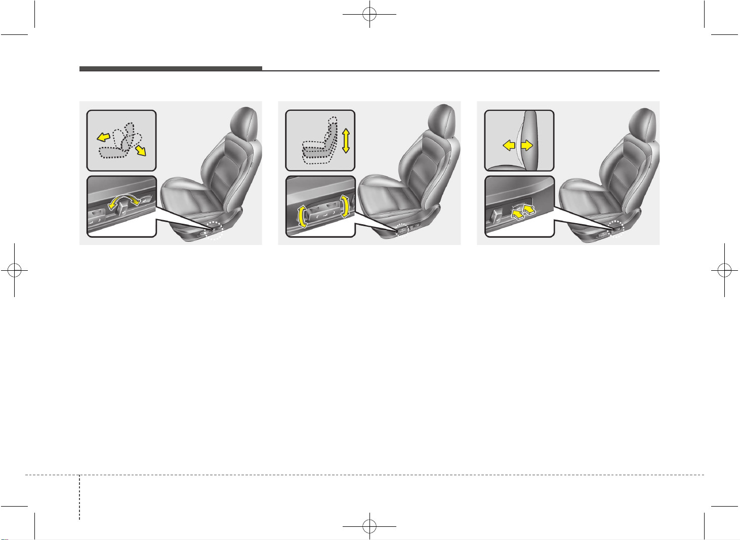
Seatback angle
1. Push the control switch forward or
rearward to move the seatback to the
desired angle.
2. Release the switch once the seat
reaches the desired position.
Seat cushion height (if equipped)
1. Pull the front portion of the control
switch up to raise or down to lower the
front part of the seat cushion. Pull the
rear portion of the control switch up to
raise or down to lower the seat cushion.
2. Release the switch once the seat
reaches the desired position.
Lumbar support (if equipped)
The lumbar support can be adjusted by
pressing the lumbar support switch on
the side of the seat.
1. Press the front portion of the switch to
increase support, or the rear portion of
the switch, to decrease support.
2. Release the switch once it reaches the
desired position.
OJD032007 OJD032008OJD032006
JD PE eng 3.QXP 03.01.2017 16:38 Page 8
39
Safety features of your vehicle
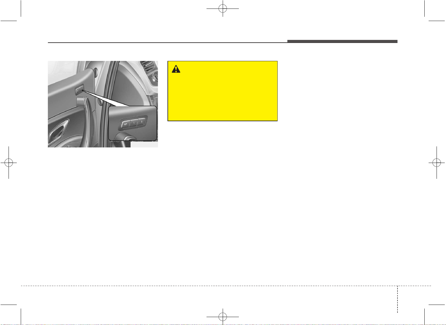
Driver position memory system
(if equipped, for automatic seat)
A driver position memory system is pro-
vided to store and recall the driver seat
position with a simple button operation.
By saving the desired position into the
system memory, different drivers can
reposition the driver seat based upon
their driving preference. If the battery is
disconnected, the position memory will
be erased and the driving position should
be restored in the system.
Storing positions into memory using
the buttons on the door
Storing driver’s seat positions
1. Shift the shift lever into P or N (for
Automatic transaxle) or Neutral (for
manual transaxle) while the engine
start/stop button is ON or ignition
switch ON.
2. Adjust the driver’s seat comfortable for
the driver.
3. Press SET button on the control panel.
The system will beep once.
4. Press one of the memory buttons (1 or
2) within 5 seconds after pressing the
SET button. The system will beep
twice when memory has been suc-
cessfully stored.
WARNING
Never attempt to operate the driver
position memory system while the
vehicle is moving.
This could result in loss of control,
and an accident causing death,
serious injury, or property damage.
OJD032054
JD PE eng 3.QXP 03.01.2017 16:38 Page 9
Safety features of your vehicle
103
Recalling positions from memory
1. Shift the shift lever into P or N (for
Automatic transaxle) or Neutral (for
manual transaxle) while the engine
start/stop button is ON or ignition
switch ON.
2. To recall the position in the memory,
press the desired memory button (1 or
2). The system will beep once, then the
driver’s seat will automatically adjust to
the stored position.
Adjusting the control switch for the dri-
ver’s seat while the system is recalling
the stored position will cause the move-
ment to stop and move in the direction
that the control switch is moved.
Easy access function (if equipped)
The system will move the driver's seat
automatically as follows:
• Without smart key system
- It will move the driver’s seat rearward
when the ignition key is removed and
front driver’s door is opened.
- It will move the driver’s seat forward
when the ignition key is inserted.
• With smart key system
- It will move the driver’s seat rearward
when the engine start/stop button is
changed to the OFF position and front
driver’s door is opened.
- It will move the driver’s seat forward
when the engine start/stop button is
changed to the ACC or START posi-
tion.
You can activate or deactivate this feature.
Refer to "User settings" in section 4.
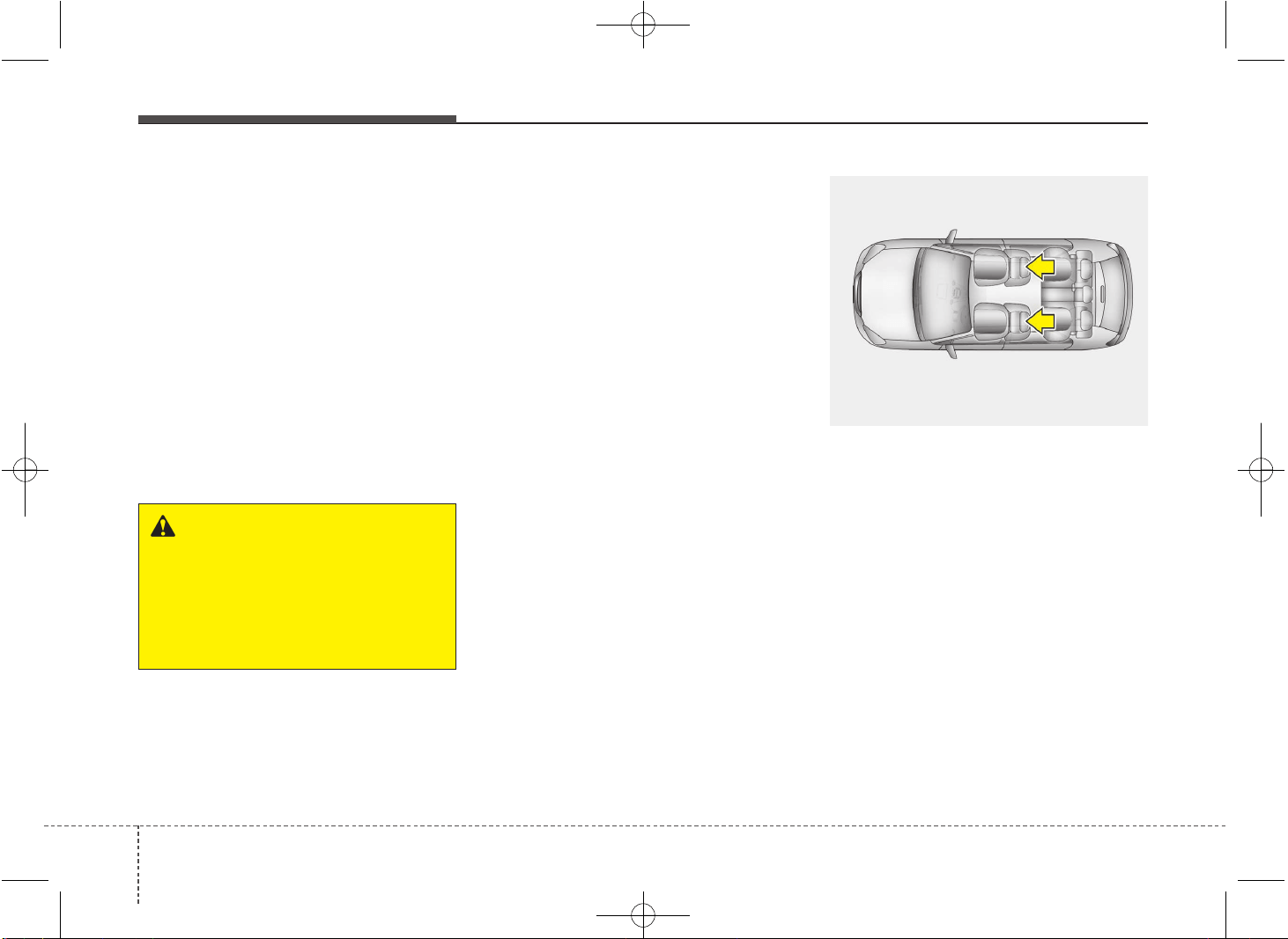
Headrest
The driver's and front passenger's seats
are equipped with a headrest for the
occupant's safety and comfort.
The headrest not only provides comfort
for the driver and front passenger, but
also helps protect the head and neck in
the event of a collision.
OPA039052
WARNING
Use caution when recalling the
adjustment memory while sitting in
the vehicle. Push the seat position
control switch to the desired posi-
tion immediately if the seat moves
too far in any direction.
JD PE eng 3.QXP 03.01.2017 16:38 Page 10
311
Safety features of your vehicle
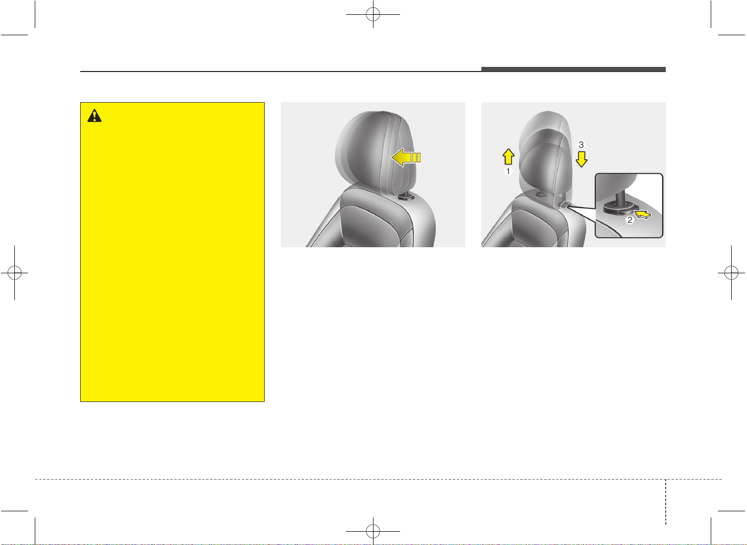
Forward and rearward adjustment
(if equipped)
The headrest may be adjusted forward to
4 different positions by pulling the head-
rest forward to the desired detent. To
adjust the headrest to it’s furthest rear-
wards position, pull it fully forward to the
farthest position and release it. Adjust the
headrest so that it properly supports the
head and neck.
Adjusting the height up and down
To raise the headrest, pull it up to the
desired position (1). To lower the head-
rest, push and hold the release button (2)
on the headrest support and lower the
headrest to the desired position (3).
OJD032009 OJD032010
WARNING
• For maximum effectiveness in
case of an accident, the headrest
should be adjusted so the middle
of the headrest is at the same
height of the center of gravity of
an occupant's head. Generally,
the center of gravity of most peo-
ple's head is similar with the
height of the top of their eyes.
Also, adjust the headrest as close
to your head as possible. For this
reason, the use of a cushion that
holds the body away from the
seatback is not recommended.
• Do not operate the vehicle with
the headrests removed as severe
injury to the occupants may
occur in the event of an accident.
Headrests may provide protec-
tion against neck injuries when
properly adjusted.
• Do not adjust the headrest posi-
tion of the driver's seat while the
vehicle is in motion.
JD PE eng 3.QXP 03.01.2017 16:38 Page 11
Safety features of your vehicle
123
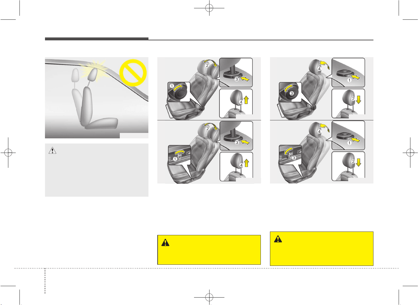
Removal and installation
To remove the headrest:
1. Recline the seatback (2) with the
recline lever or switch (1).
2. Raise headrest as far as it can go.
3. Press the headrest release button (3)
while pulling the headrest up (4).
To reinstall the headrest :
1. Put the headrest poles (2) into the holes
while pressing the release button (1).
2. Recline the seatback (4) with the
recline lever or switch (3).
3. Adjust the headrest to the appropriate
height.
WARNING
NEVER allow anyone to ride in a seat
with the headrest removed.
WARNING
Always make sure the headrest
locks into position after reinstalling
and adjusting it properly.
OJD033069
OJD033071
■ Type A
■ Type B
OJD033068
OJD033070
■ Type A
■ Type B
OYFH034205
CAUTION
If you recline the seatback towards
the front with the head restraint and
seat cushion raised, the head
restraint may come in contact with
the sunvisor or other parts of the
vehicle.
JD PE eng 3.QXP 03.01.2017 16:38 Page 12
313
Safety features of your vehicle
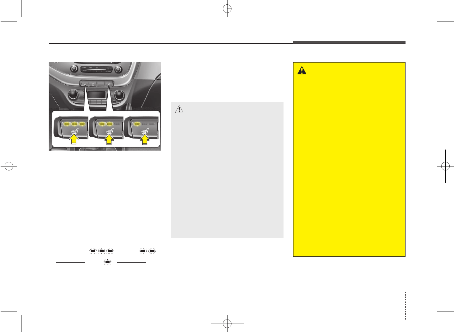
Seat warmer (if equipped)
The seat warmer is provided to warm the
front seats during cold weather. With the
ignition switch in the ON position, push
either of the switches to warm the driver's
seat or the front passenger's seat.
During mild weather or under conditions
where the operation of the seat warmer
is not needed, keep the switches in the
"OFF" position.
• Each time you press the switch, the
temperature setting of the seat will
change as follows :
• The seat warmer defaults to the OFF
position whenever the ignition switch is
turned on.
✽✽
NOTICE
With the seat warmer switch in ON
position, the heating system in the seat
turns off or on automatically depending
on the seat temperature.
CAUTION - Seat damage
• When cleaning the seats, do not
use an organic solvent such as
paint thinner, benzene, alcohol and
gasoline. Doing so may damage
the surface of the heater or seats.
• To prevent overheating the seat
warmer, do not place anything on
the seats that insulates against
heat, such as blankets, cushions
or seat covers on the seats while
the seat warmer is in operation.
• Do not place heavy or sharp
objects on seats equipped with
seat warmers. Damage to the seat
warming components could occur.
• Do not change the seat cover. It
may damage the seat warmer.
WARNING - Seat warmer
burns
Passengers should use extreme
caution when using seat warmers
due to the possibility of excess
heating or burns. The occupants
must be able to feel if the seat is
becoming too warm and to turn the
seat warmer off. The seat warmer
may cause burns even at low tem-
peratures, especially if used for
long periods of time.
In particular, the driver must exer-
cise extreme care for the following
types of passengers:
1. Infants, children, elderly or dis-
abled persons, or hospital outpa-
tients
2. Persons with sensitive skin or
those that burn easily
3. Fatigued individuals
4. Intoxicated individuals
5. Individuals taking medication
that can cause drowsiness or
sleepiness (sleeping pills, cold
tablets, etc.)
OJD032012
OFF → HIGH ( ) → MID ( )
LOW ( )
→
→
JD PE eng 3.QXP 03.01.2017 16:39 Page 13
Safety features of your vehicle
143
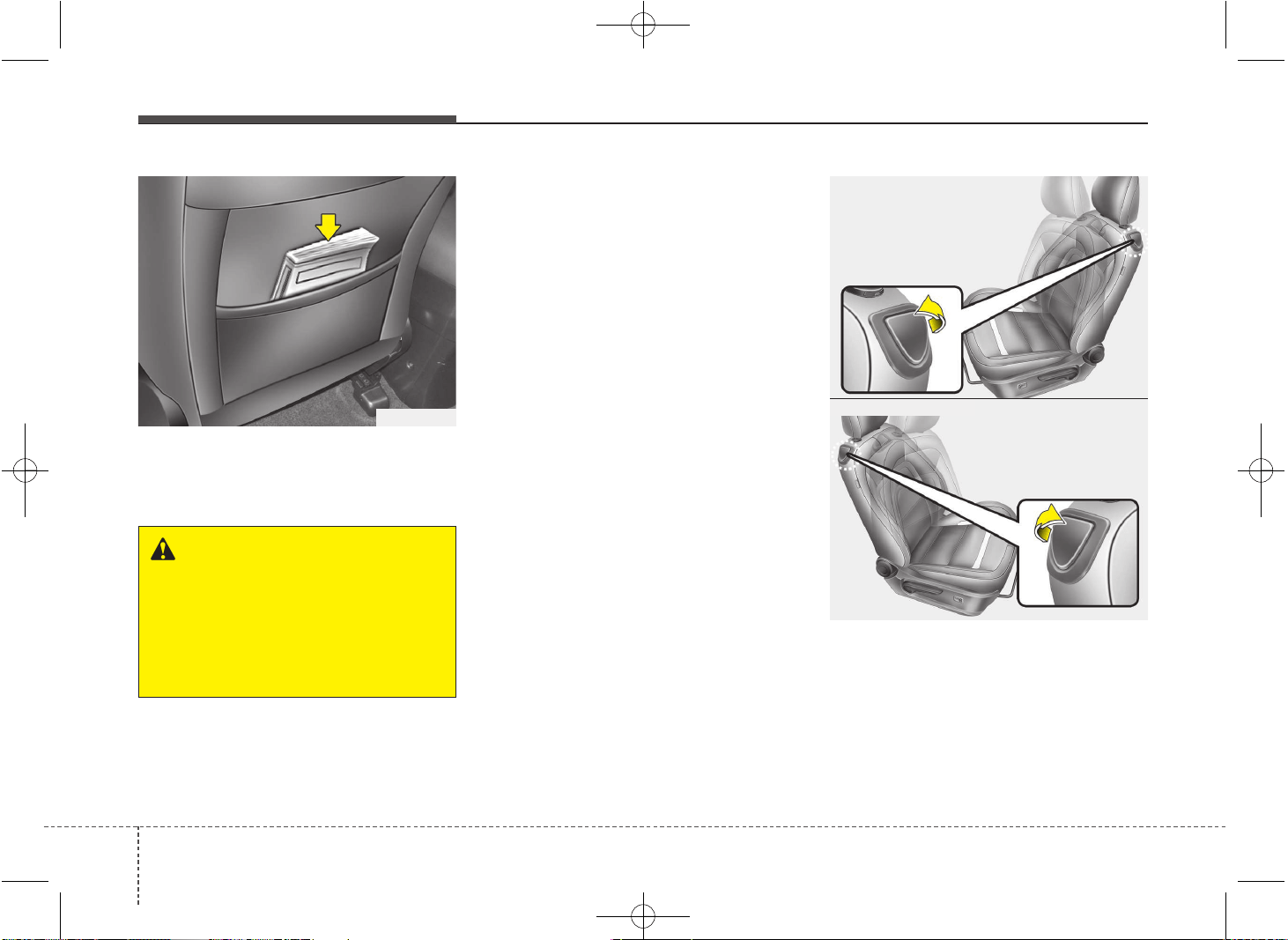
Seatback pocket (if equipped)
The seatback pocket is provided on the
back of the front passenger’s and driver’s
seatbacks.
Rear Seat Entry
(For 3-door vehicle only)
To get in or get out of the rear seat, the
driver’s or front passenger’s seat should
be folded and the seat should be slide.
1. Fold the front seatback by pulling up
the walk-in seat lever and then slide
the front seat forward.
OJD033064E
OJD033065
Driver’s seat
Front passenger’s seat
OJD032013
WARNING - Seatback
pockets
Do not put heavy or sharp objects
in the seatback pockets. In an acci-
dent they could come loose from
the pocket and injure vehicle occu-
pants.
JD PE eng 3.QXP 03.01.2017 16:39 Page 14
315
Safety features of your vehicle
2. Set the belt extension guide to position
(3).
3. After getting in or getting out, slide the
seat rearward while holding the seat
cushion and then push the seatback
rearward. And set the belt extension
guide to position (1) or (2).
Rear seat
Headrest
The rear seat is equipped with headrests
in all the seating positions for the occu-
pant's safety and comfort.
The headrest not only provides comfort
for passengers, but also helps protect the
head and neck in the event of a collision.
OPA039053
WARNING
• For maximum effectiveness in
case of an accident, the headrest
should be adjusted so the middle
of the headrest is at the same
height of the center of gravity of
an occupant's head. Generally,
the center of gravity of most peo-
ple's head is similar with the
height of the top of their eyes.
Also adjust the headrest as close
to your head as possible. For this
reason, the use of a cushion that
holds the body away from the
seatback is not recommended.
• Do not operate the vehicle with
the headrests removed. Severe
injury to an occupant may occur
in the event of an accident.
Headrests may provide protec-
tion against severe neck injuries
when properly adjusted.
*
* if equipped
OJK032061
JD PE eng 3.QXP 03.01.2017 16:39 Page 15
Safety features of your vehicle
163
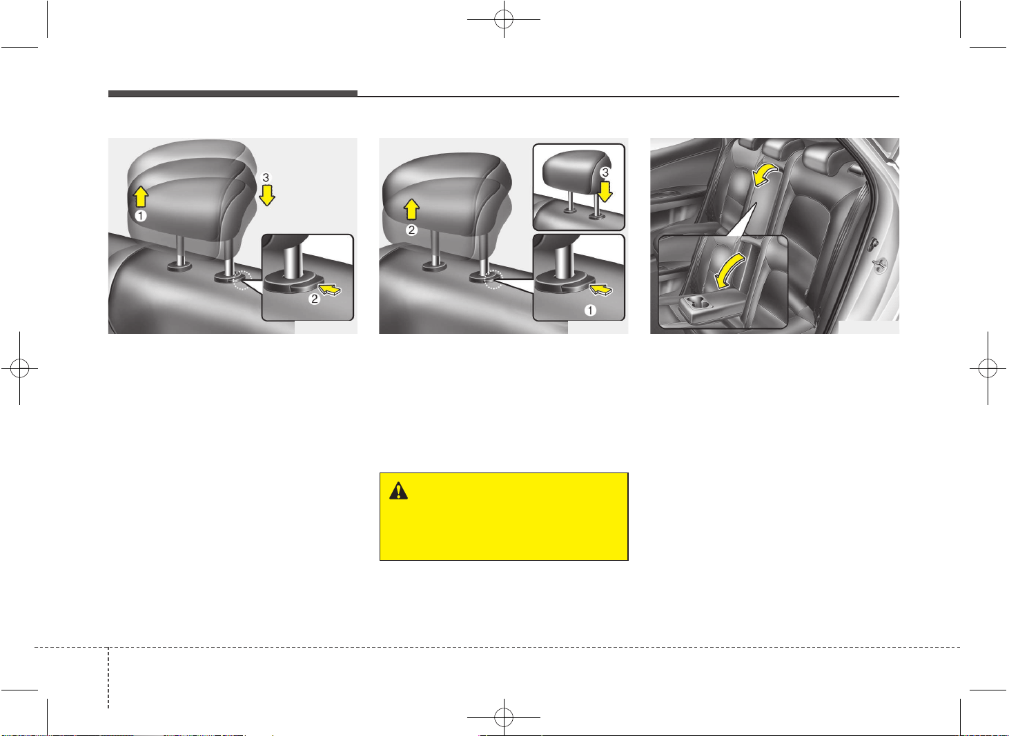
Adjusting the height up and down
To raise the headrest, pull it up to the
desired position (1). To lower the head-
rest, push and hold the release button (2)
on the headrest support and lower the
headrest to the desired position (3).
Removal and installation
To remove the headrest, raise it as far as
it can go then press the release button
(1) while pulling the headrest up (2).
To reinstall the headrest, put the head-
rest poles (3) into the holes while press-
ing the release button (1). Then adjust it
to the appropriate height.
Armrest (if equipped)
To use the armrest, pull it forward from
the seatback.
OJD032015
WARNING
Make sure the headrest locks in
position after adjusting it to proper-
ly protect the occupants.
OJD032016OJD032014
JD PE eng 3.QXP 03.01.2017 16:39 Page 16
317
Safety features of your vehicle
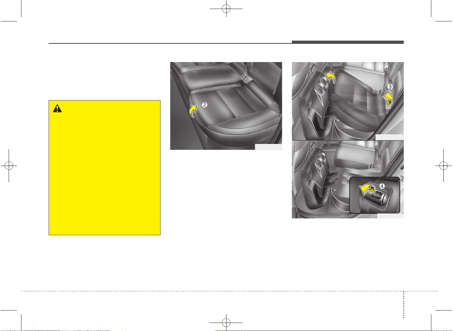
Folding the rear seat
The rear seatbacks (or cushions) may be
folded to facilitate carrying long items or
to increase the luggage capacity of the
vehicle.
To fold the rear seat cushion and back
(5 Door and Wagon)
1. Set the front seatback to the upright
position and if necessary, slide the
front seat forward.
2. Lift the front portion of the seat cush-
ion up.
3. Lift the rear portion of the seat cush-
ion. Stand the rear seat cushion verti-
cally.
4. Pull the lock release lever (red visible).
OJD032018
OJD032019
OJD032017
WARNING
The purpose of the fold-down rear
seatbacks (or cushions) is to allow
you to carry longer objects than
could otherwise be accommodated.
Never allow passengers to sit on
top of the folded down seatback
while the car is moving as this is
not a proper seating position and
no seat belts are available for use.
This could result in serious injury
or death in case of an accident or
sudden stop. Objects carried on the
folded down seatback should not
extend higher than the top of the
front seats. This could allow cargo
to slide forward and cause injury or
damage during sudden stops.
JD PE eng 3.QXP 03.01.2017 16:39 Page 17
Safety features of your vehicle
183
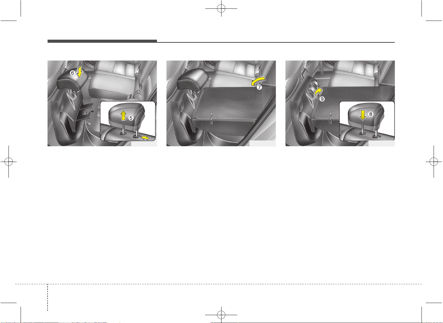
5. Remove the headrest from the rear
seatback.
6. Stow the headrest by inserting the
headrest poles into the holder on the
bottom of the seat cushion.
7. Fold the rear seatback forward and
down firmly.
8. To use the rear seat, reposition the
headrest on the seatback and adjust it
to the desired position.
9. Lift and push the seatback backward
firmly until it clicks into place. Make
sure the seatback is locked in place
(red invisible).
OJD032021 OJD032022OJD032020
JD PE eng 3.QXP 03.01.2017 16:39 Page 18
319
Safety features of your vehicle
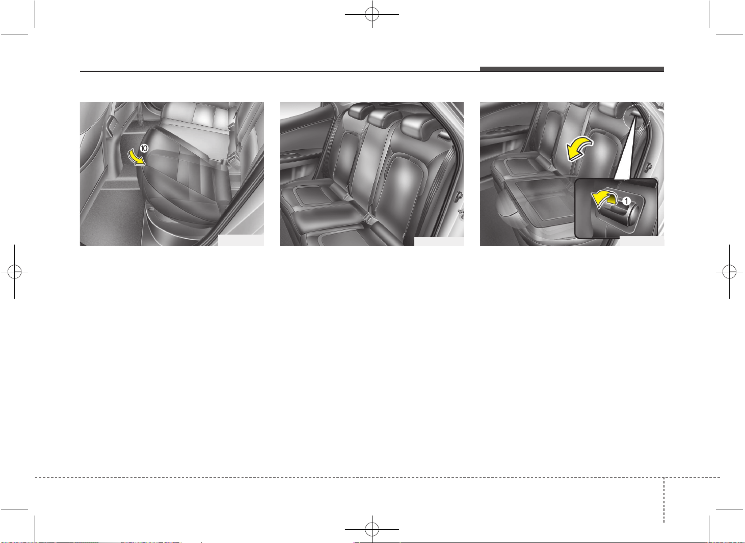
10. Return the seat cushion to the origi-
nal position by pushing down the rear
side of the seat cushion first. Make
sure the seat cushion is locked in
place.
11. Return the rear seat belt to the prop-
er position.
To fold down the rear seatback
(for 3 Door):
1. Set the front seatback to the upright
position and if necessary, slide the
front seat forward.
2. Lower the rear headrests to the lowest
position.
3.Pull the lock release lever (1) and fold
the rear seatback forward and down
firmly.
If the seat belt locks after unfolding the
rear seatback, pull out the locked seat
belt, release it then pull it out again.
OJD035076L OJD033067OJD032023
JD PE eng 3.QXP 03.01.2017 16:40 Page 19
Safety features of your vehicle
203
To unfold the rear seat
1. To use the rear seat, lift and pull the
seatback backward. Pull the seatback
firmly until it clicks into place. Make
sure the seatback is locked in place.
When you return the seatback to its
upright position, always be sure it has
locked into position by pushing on the
top of the seatback.
If you can not see the red line at the
bottom of folding lever, it means the
seatback is locked completely.
2. Return the rear seat belt to the proper
position.
3. When the seatback is completely
installed, check the seatback folding
lever again.
WARNING
When you return the rear seatback
to its upright position after being
folded down:
Be careful not to damage the seat
belt webbing or buckle. Do not
allow the seat belt webbing or
buckle to get caught or pinched in
the rear seat. Ensure that the seat-
back is completely locked into its
upright position by pushing on the
top of the seatback. Otherwise, in
an accident or sudden stop, the
seat could fold down and allow
cargo to enter the passenger com-
partment, which could result in
serious injury or death.
CAUTION - Rear seat belts
When returning the rear seatbacks
to the upright position, remember
to return the rear shoulder belts to
their proper position.
WARNING - Cargo
Cargo should always be secured to
prevent it from being thrown about
the vehicle in a collision and caus-
ing injury to the vehicle occupants.
Special care should be taken of
objects placed in the rear seats,
since those may hit the front seat
occupants in a frontal collision.
WARNING - Cargo loading
Make sure the engine is off, the
automatic transaxle is in P (Park)
or the manual transaxle is in R
(Reverse) or 1st, and the parking
brake is securely applied whenever
loading or unloading cargo. Failure
to take these steps may allow the
vehicle to move if the shift lever is
inadvertently moved to another
position.
JD PE eng 3.QXP 03.01.2017 16:40 Page 20
321
Safety features of your vehicle
Seat belt restraint system
SEAT BELTS
(Continued)
• Avoid wearing twisted seat belts.
A twisted belt can't do its job as
well. In a collision, it could even
cut into you. Be sure the belt web-
bing is straight and not twisted.
• Be careful not to damage the belt
webbing or hardware. If the belt
webbing or hardware is dam-
aged, replace it.
WARNING
Seat belts are designed to bear
upon the bony structure of the
body, and should be worn low
across the front of the pelvis or the
pelvis, chest and shoulders, as
applicable; wearing the lap section
of the belt across the abdominal
area must be avoided.
Seat belts should be adjusted as
firmly as possible, consistent with
comfort, to provide the protection
for which they have been designed.
A slack belt will greatly reduce the
protection afforded to the wearer.
(Continued)
WARNING
• For maximum restraint system
protection, the seat belts must
always be used whenever the car
is moving.
• Seat belts are most effective
when seatbacks are in the
upright position.
• Children age 12 and younger must
always be properly restrained in
the rear seat. Never allow children
to ride in the front passenger seat.
If a child over 12 must be seated in
the front seat, he/she must be
properly belted and the seat
should be moved as far back as
possible.
• Never wear the shoulder belt
under your arm or behind your
back. An improperly positioned
shoulder belt can cause serious
injuries in a crash. The shoulder
belt should be positioned midway
over your shoulder across your
collarbone.
(Continued)
(Continued)
Care should be taken to avoid con-
tamination of the webbing with pol-
ishes, oils and chemicals, and par-
ticularly battery acid.
Cleaning may safely be carried out
using mild soap and water. The belt
should be replaced if webbing
becomes frayed, contaminated or
damaged. It is essential to replace
the entire assembly after it has
been worn in a severe impact even
if damage to the assembly is not
obvious. Belts should not be worn
with straps twisted. Each belt
assembly must only be used by one
occupant; it is dangerous to put a
belt around a child being carried on
the occupant's lap.
JD PE eng 3.QXP 03.01.2017 16:40 Page 21
Safety features of your vehicle
223
Seat belt warning
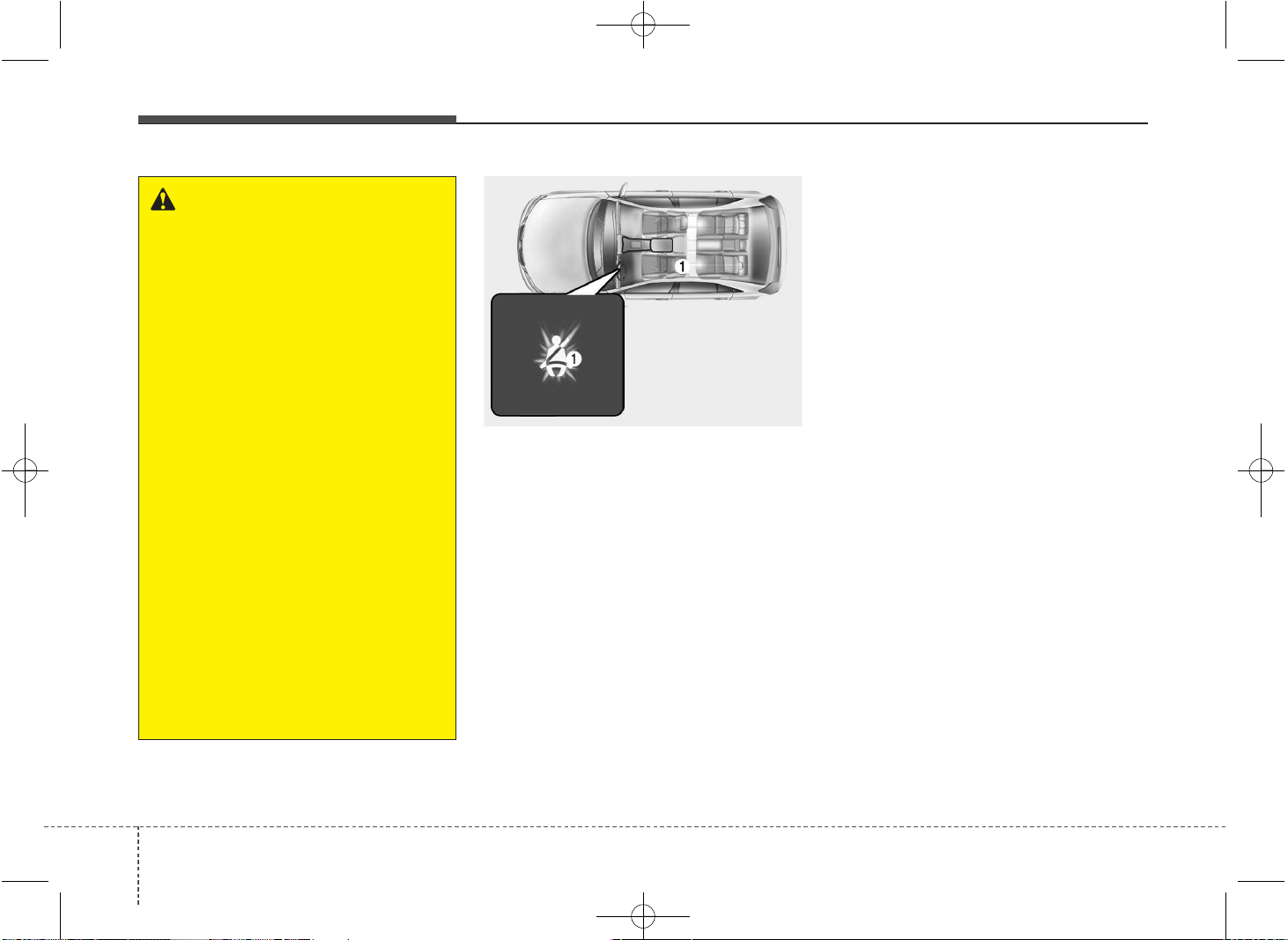
Driver’s seat belt warning (1)
As a reminder to the driver, the seat belt
warning light will illuminate for approxi-
mately 6 seconds each time you turn the
ignition switch ON regardless of belt fas-
tening.
If the driver’s seat belt is unfastened after
the ignition switch is ON, the seat belt
warning light illuminates until the belt is
fastened.
If you continue not to fasten the seat belt
and you drive over 9km/h, the illuminated
warning light will start to blink until you
drive under 6km/h. (if equipped)
If you continue not to fasten the seat belt
and you drive over 20km/h the seat belt
warning chime will sound for approxi-
mately 100 seconds and the correspon-
ding warning light will blink. (if equipped)
WARNING
• No modifications or additions
should be made by the user
which will either prevent the seat
belt adjusting devices from oper-
ating to remove slack, or prevent
the seat belt assembly from being
adjusted to remove slack.
• When you fasten the seat belt, be
careful not to latch the seat belt in
buckles of other seat. It's very dan-
gerous and you may not be pro-
tected by the seat belt properly.
• Do not unfasten the seat belt and
do not fasten and unfasten the
seat belt repeatedly while driving.
This could result in loss of con-
trol, and an accident causing
death, serious injury, or property
damage.
• When fastening the seat belt,
make sure that the seat belt does
not pass over objects that are
hard or can break easily.
• Make sure there is nothing in the
buckle. The seat belt may not be
fastened securely.
OAM032161L
JD PE eng 3.QXP 03.01.2017 16:40 Page 22
323
Safety features of your vehicle
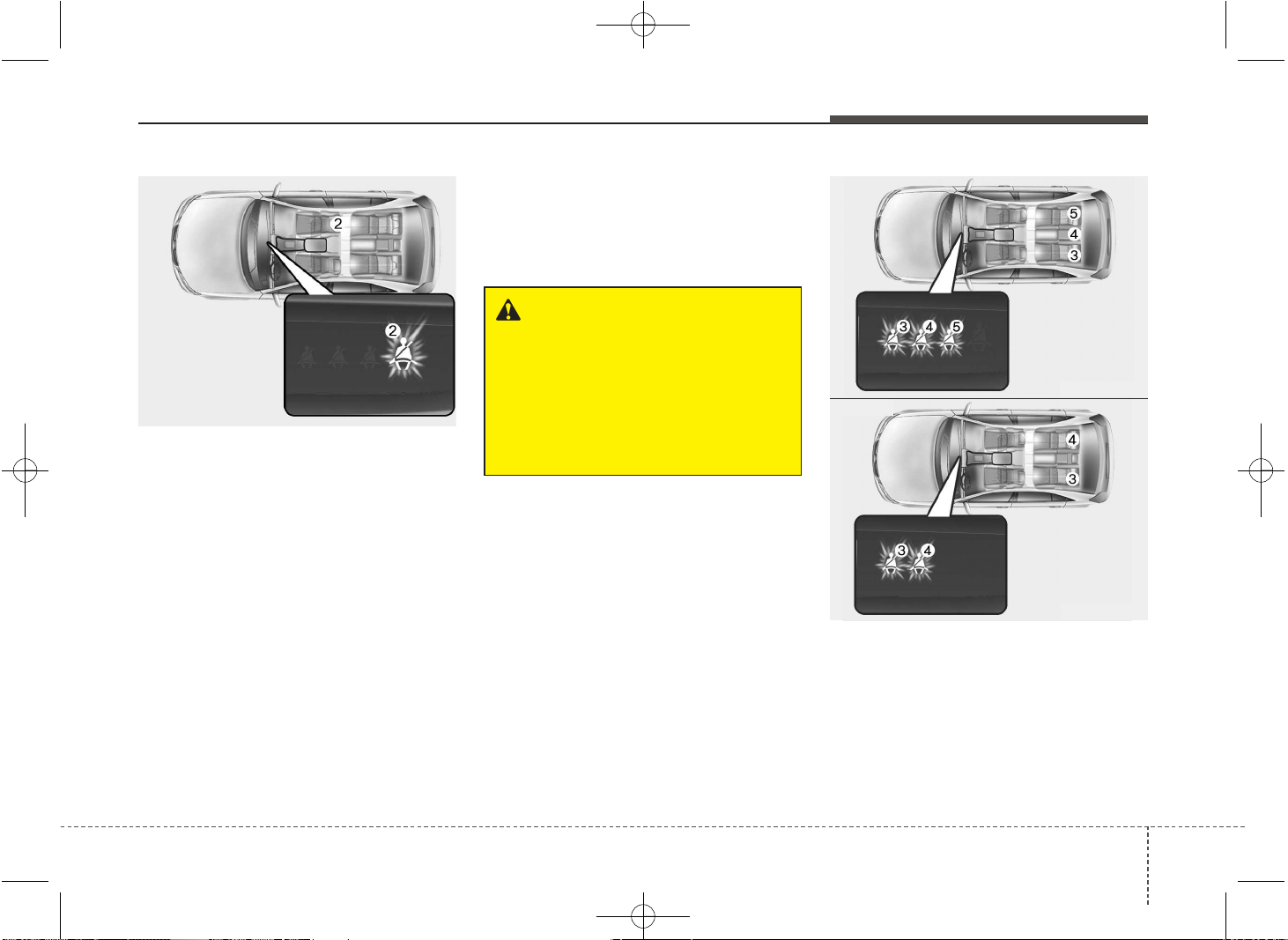
Front passenger’s seat belt warning (2)
As a reminder to the front passenger, the
front passenger’s seat belt warning lights
will illuminate for approximately 6 sec-
onds each time you turn the ignition
switch ON regardless of belt fastening.
If the front passenger’s seat belt is not
fastened when the ignition switch is
turned ON or if it is disconnected after
the ignition switch is turned ON, the cor-
responding seat belt warning light will
illuminate until the belt is fastened.
If you continue not to fasten the seat belt
and you drive over 9km/h, the illuminated
warning light will start to blink until you
drive under 6km/h.
If you continue not to fasten the seat belt
and you drive over 20km/h the seat belt
warning chime will sound for approxi-
mately 100 seconds and the correspon-
ding warning light will blink.
✽✽
NOTICE
• You can find the front passenger’s
seat belt warning light on the center
fascia panel.
• Although the front passenger seat is
not occupied, the seat belt warning
light will blink or illuminate for 6 sec-
onds.
• The front passenger's seat belt warn-
ing may operate when luggage is
placed on the front passenger seat.
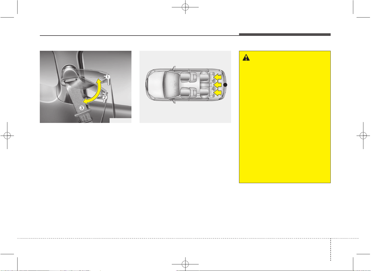
Rear passenger’s seat belt warning (3,4,5)
If the ignition switch is turned ON(engine
is not running) when the rear passen-
ger's lap/shoulder belt is not fastened,
the corresponding seat belt warning light
will illuminate until the belt is fastened.
OJD032024
OJD032025
OJD032058
■ Type A
■ Type B
WARNING
Riding in an improper position
adversely affects the front passen-
ger’s seat belt warning system. It is
important for the driver to instruct
the passenger as to the proper
seating instructions as contained
in this manual.
JD PE eng 3.QXP 03.01.2017 16:40 Page 23
Safety features of your vehicle
243
And then, the rear corresponding seat
belt warning light will illuminate for
approximately 35 seconds, if any of fol-
lowing occurs;
- You start the engine when the rear belt
is not fastened.
- You drive over 9km/h when the rear belt
is not fastened.
- The rear belt is disconnected when
driving under 20km/h.
If the rear seat belt is fastened, the warn-
ing light will turn off immediately.
If the rear seat belt is disconnected when
you drive over the 20km/h, the corre-
sponding seat belt warning light will blink
and warning chime will sound for 35 sec-
onds.
But, if the rear passenger's lap/shoulder
belt is/are connected and disconnected
twice within 9 seconds after the belt is
fastened, the corresponding seat belt
warning light will not operate.
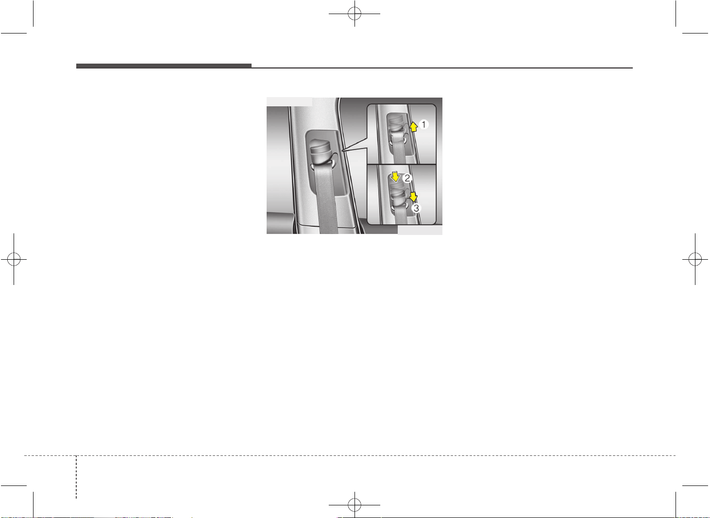
Lap/shoulder belt
Height adjustment (5 Door and Wagon)
You can adjust the height of the shoulder
belt anchor to one of 4 positions for max-
imum comfort and safety.
The height of the adjusting seat belt
should not be too close to your neck. You
will not be getting the most effective pro-
tection. The shoulder portion should be
adjusted so that it lies across your chest
and midway over your shoulder near the
door and not your neck.
To adjust the height of the seat belt
anchor, lower or raise the height adjuster
into an appropriate position.
To raise the height adjuster, pull it up (1).
To lower it, push it down (3) while press-
ing the height adjuster button (2).
Release the button to lock the anchor
into position. Try sliding the height
adjuster to make sure that it has locked
into position.
OLM039026
■ Front seat
JD PE eng 3.QXP 03.01.2017 16:40 Page 24
325
Safety features of your vehicle
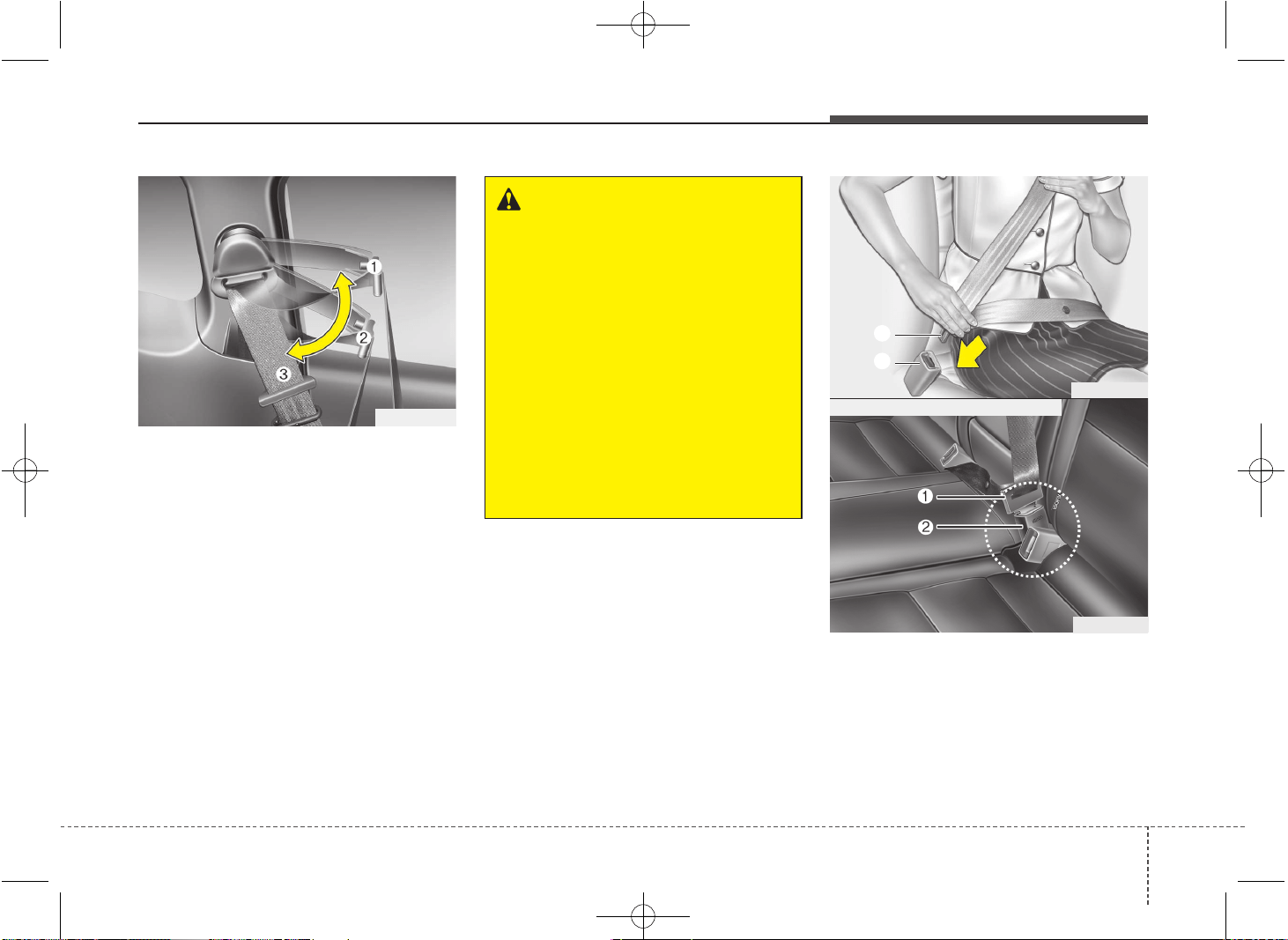
Shoulder belt extension guide
(For 3-door vehicle only)
You can adjust the position of the shoul-
der belt extension guide for easier
access to the shoulder belt.
• Set the belt extension guide to the posi-
tion (1~2) when using the seat belt.
• Set the belt extension guide to the
position (3) when getting in or getting
out of the rear seat.
To fasten your seat belt:
To fasten your seat belt, pull it out of the
retractor and insert the metal tab (1) into
the buckle (2). There will be an audible
"click" when the tab locks into the buckle.
WARNING
• Verify the shoulder belt anchor is
locked into position at the appro-
priate height. Never position the
shoulder belt across your neck or
face. Improperly positioned seat
belts can cause serious injuries
in an accident.
• Failure to replace seat belts after
an accident could leave you with
damaged seat belts that will not
provide protection in the event of
another collision leading to per-
sonal injury or death. Replace
your seat belts after being in an
accident as soon as possible.
OJK032061
B180A01NF
1
2
OJD032026
■ Rear center seat belt (if equipped)
JD PE eng 3.QXP 03.01.2017 16:40 Page 25
Safety features of your vehicle
263
The seat belt automatically adjusts to the
proper length only after the lap belt por-
tion is adjusted manually so that it fits
snugly around your hips. If you lean for-
ward in a slow, easy motion, the belt will
extend and let you move around. If there
is a sudden stop or impact, however, the
belt will lock into position. It will also lock
if you try to lean forward too quickly.
✽✽
NOTICE
If you are not able to pull out the seat
belt from the retractor, firmly pull the
belt out and release it. Then you will be
able to pull the belt out smoothly.
To release the seat belt:
The seat belt is released by pressing the
release button (A) in the locking buckle.
When it is released, the belt should auto-
matically draw back into the retractor.
If this does not happen, check the belt to
be sure it is not twisted, then try again.
CAUTION
When using the rear center seat
belt, the buckle with the “CENTER”
mark must be used.
B200A01NF
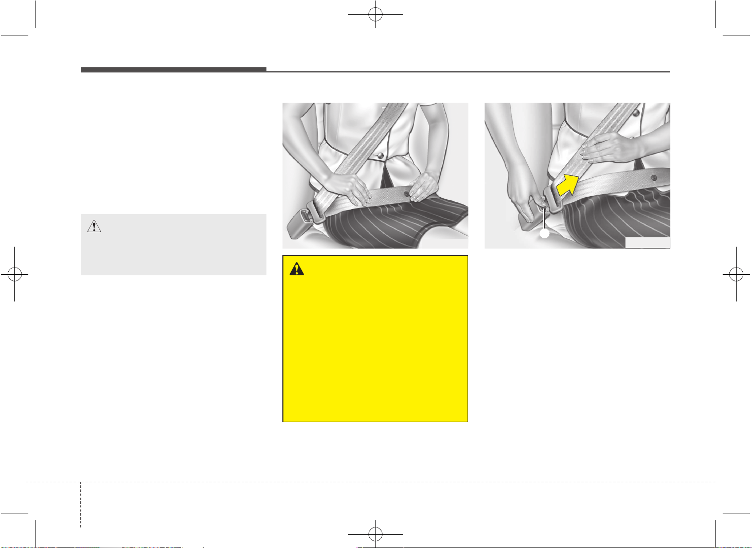
WARNING
You should place the lap belt por-
tion as low as possible and snugly
across your hips, not on your waist.
If the lap belt is located too high on
your waist, it may increase the
chance of injury in the event of a
collision. Both arms should not be
under or over the belt. Rather, one
should be over and the other under,
as shown in the illustration.
Never wear the seat belt under the
arm near the door.
B210A01NF
A
JD PE eng 3.QXP 03.01.2017 16:40 Page 26
327
Safety features of your vehicle
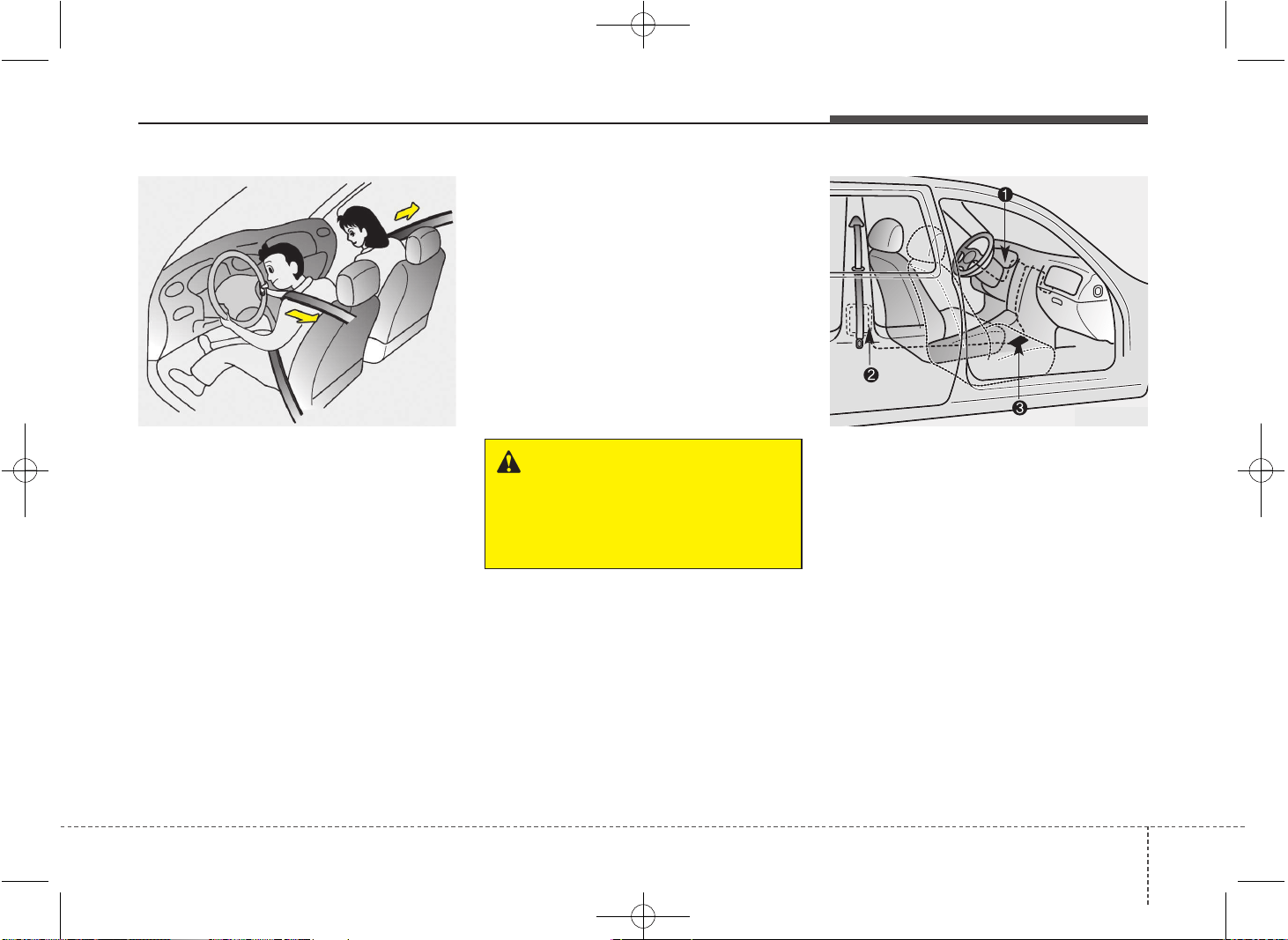
Pre-tensioner seat belt
Your vehicle is equipped with driver's and
front passenger's pre-tensioner seat
belts. The purpose of the pre-tensioner is
to make sure that the seat belts fit tightly
against the occupant's body in certain
frontal collisions. The pre-tensioner seat
belts may be activated in crashes where
the frontal collision is severe enough.
When the vehicle stops suddenly, or if
the occupant tries to lean forward too
quickly, the seat belt retractor will lock
into position. In certain frontal collisions,
the pre-tensioner will activate and pull
the seat belt into tighter contact against
the occupant's body.
If the system senses excessive seat belt
tension on the driver or passenger's seat
belt when the pre-tensioner activates, the
load limiter inside the pre-tensioner will
release some of the pressure on the
affected seat belt.
The seat belt pre-tensioner system con-
sists mainly of the following components.
Their locations are shown in the illustra-
tion:
1. SRS air bag warning light
2. Retractor pre-tensioner assembly
3. SRS control module
WARNING
For your safety, be sure that the
belt webbing is not loose or twisted
and always sit properly on your
seat.
OED030300
8KMB3311
JD PE eng 3.QXP 03.01.2017 16:40 Page 27
Safety features of your vehicle
283
✽✽
NOTICE
• When the pre-tensioner seat belts are
activated, a loud noise may be heard
and fine dust, which may appear to be
smoke, may be visible in the passenger
compartment. These are normal oper-
ating conditions and are not hazardous.
• Although it is harmless, the fine dust
may cause skin irritation and should
not be breathed for prolonged periods.
Wash all exposed skin areas thorough-
ly after an accident in which the pre-
tensioner seat belts were activated.
• Because the sensor that activates the
SRS air bag is connected with the pre-
tensioner seat belt, the SRS air bag
warning light on the instrument panel
will illuminate for approximately 6
seconds after the ignition switch has
been turned to the ON position, and
then it should turn off.
WARNING
To obtain maximum benefit from a
pre-tensioner seat belt:
1. The seat belt must be worn cor-
rectly and adjusted to the proper
position. Please read and follow
all of the important information
and precautions about your vehi-
cle’s occupant safety features –
including seat belts and air bags –
that are provided in this manual.
2. Be sure you and your passen-
gers always wear seat belts prop-
erly.
CAUTION
If the pre-tensioner seat belt is not
working properly, the SRS air bag
warning light will illuminate even if
there is no malfunction of the SRS
air bag. If the SRS air bag warning
light does not illuminate when the
ignition key is turned to ON, or if it
remains illuminated after illuminat-
ing for approximately 6 seconds, or
if it illuminates while the vehicle is
being driven, we recommend that
the system be inspected by an
authorized Kia dealer.
JD PE eng 3.QXP 03.01.2017 16:40 Page 28
329
Safety features of your vehicle
Seat belt precautions
WARNING
• Pre-tensioners are designed to
operate only one time. After acti-
vation, pre-tensioner seat belts
must be replaced. All seat belts,
of any type, should always be
replaced after they have been
worn during a collision.
• The pre-tensioner seat belt
assembly mechanisms become
hot during activation. Do not
touch the pre-tensioner seat belt
assemblies for several minutes
after they have been activated.
• Do not attempt to inspect or
replace the pre-tensioner seat
belts yourself. We recommend
that the system be inspected by
an authorized Kia dealer.
• Do not attempt to service or
repair the pre-tensioner seat belt
system in any manner.
(Continued)
WARNING
All occupants of the vehicle must
wear their seat belts at all times.
Seat belts and child restraints
reduce the risk of serious or fatal
injuries for all occupants in the
event of a collision or sudden stop.
Without a seat belt, occupants
could be shifted too close to a
deploying air bag, strike the interior
structure or be thrown from the
vehicle. Properly worn seat belts
greatly reduce these hazards.
Always follow the precautions
about seat belts, air bags and occu-
pant seat contained in this manual.
(Continued)
• Improper handling of the pre-ten-
sioner seat belt assemblies, and
failure to heed the warnings not
to strike, modify, inspect, replace,
service or repair the pre-tensioner
seat belt assemblies may lead to
improper operation or inadvertent
activation and serious injury.
• Always wear the seat belts when
driving or riding in a motor vehicle.
• If the vehicle or pre-tensioner seat
belt must be discarded, we rec-
ommend that you contact an
authorized Kia dealer.
JD PE eng 3.QXP 03.01.2017 16:40 Page 29
Safety features of your vehicle
303
Infant or small child
You should be aware of the specific
requirements in your country. Child
and/or infant seats must be properly
placed and installed in the rear seat. For
more information about the use of these
restraints, refer to “Child restraint sys-
tem” in this section.
✽✽
NOTICE
Small children are best protected from
injury in an accident when properly
restrained in the rear seat by a child
restraint system that meets the require-
ments of the Safety Standards of your
country. Before buying any child
restraint system, make sure that it has a
label certifying that it meets Safety
Standards of your country. The restraint
must be appropriate for your child's
height and weight. Check the label on
the child restraint for this information.
Refer to “Child restraint system” in this
section.
Larger children
Children who are too large for child
restraint systems should always occupy
the rear seat and use the available
lap/shoulder belts. The lap portion should
be fastened and snugged on the hips
and as low as possible. Check if the belt
fits periodically. A child's squirming could
put the belt out of position. Children are
afforded the most safety in the event of
an accident when they are restrained by
a proper restraint system in the rear seat.
If a larger child (over age 12) must be
seated in the front seat, the child should
be securely restrained by the available
lap/shoulder belt and the seat should be
placed in the rearmost position. Children
age 12 and under should be restrained
securely in the rear seat. NEVER place a
child age 12 and under in the front seat.
NEVER place a rear facing child seat in
the front seat of a vehicle.
WARNING
Every person in your vehicle needs
to be properly restrained at all
times, including infants and chil-
dren. Never hold a child in your
arms or lap when riding in a vehi-
cle. The violent forces created dur-
ing a crash will tear the child from
your arms and throw the child
against the interior. Always use a
child restraint appropriate for your
child's height and weight.
JD PE eng 3.QXP 03.01.2017 16:40 Page 30
331
Safety features of your vehicle
WARNING - Pregnant
women
Pregnant women must never place
the lap portion of the safety belt
over the area of the abdomen
where the fetus is located or above
the abdomen where the belt could
crush the fetus during an impact.
If the shoulder belt portion slightly touch-
es the child’s neck or face, try placing the
child closer to the center of the vehicle. If
the shoulder belt still touches their face
or neck they need to be returned to a
child restraint system.
Pregnant women
The use of a seat belt is recommended
for pregnant women to lessen the chance
of injury in an accident. When a seat belt
is used, the lap belt portion should be
placed as low and snugly as possible on
the hips, not across the abdomen. For
specific recommendations, consult a
physician.
Injured person
A seat belt should be used when an
injured person is being transported.
When this is necessary, you should con-
sult a physician for recommendations.
One person per belt
Two people (including children) should
never attempt to use a single seat belt.
This could increase the severity of
injuries in case of an accident.
Do not lie down
To reduce the chance of injuries in the
event of an accident and to achieve max-
imum effectiveness of the restraint sys-
tem, all passengers should be sitting up
and the front seats should be in an
upright position when the car is moving.
A seat belt cannot provide proper protec-
tion if the person is lying down in the rear
seat or if the front seat is in a reclined
position.
WARNING - Shoulder belts
on small children
• Never allow a shoulder belt to be
in contact with a child’s neck or
face while the vehicle is in
motion.
• If seat belts are not properly worn
and adjusted on children, there is
a risk of death or serious injury.
JD PE eng 3.QXP 03.01.2017 16:40 Page 31
Safety features of your vehicle
323
Care of seat belts
Seat belt systems should never be disas-
sembled or modified. In addition, care
should be taken to assure that seat belts
and belt hardware are not damaged by
seat hinges, doors or other abuse.
Periodic inspection
It is recommended that all seat belts be
inspected periodically for wear or dam-
age of any kind. Any damaged parts
should be replaced as soon as possible.
Keep belts clean and dry
Seat belts should be kept clean and dry.
If belts become dirty, they can be
cleaned by using a mild soap solution
and warm water. Bleach, dye, strong
detergents or abrasives should not be
used because they may damage and
weaken the fabric.
When to replace seat belts
Entire in-use seat belt assembly or
assemblies should be replaced if the
vehicle has been involved in an accident.
This should be done even if no damage
is visible. We recommend that you con-
sult an authorized Kia dealer.
WARNING
Riding with a reclined seatback
increases your chance of serious
or fatal injuries in the event of a col-
lision or sudden stop. The protec-
tion of your restraint system (seat
belts and air bags) is greatly
reduced by reclining your seat.
Seat belts must be snug against
your hips and chest to work proper-
ly. The more the seatback is
reclined, the greater the chance
that an occupant's hips will slide
under the lap belt causing serious
internal injuries or the occupant's
neck could strike the shoulder belt.
Drivers and passengers should
always sit well back in their seats,
properly belted, and with the seat-
backs upright.
WARNING
• When you return the rear seat-
back to its upright position after
the rear seatback was folded
down, be careful not to damage
the seat belt webbing or buckle.
Be sure that the webbing or buck-
le does not get caught or pinched
in the rear seat. A seat belt with
damaged webbing or buckle will
not be as strong and could possi-
bly fail during a collision or sud-
den stop, resulting in serious
injury. If the webbing or buckles
are damaged, get them replaced
immediately.
• Seatbelts can become hot in a
vehicle that has been closed up
in sunny weather.
They could burn infants and chil-
dren.
JD PE eng 3.QXP 03.01.2017 16:40 Page 32
333
Safety features of your vehicle
CHILD RESTRAINT SYSTEM (IF EQUIPPED)
Children riding in the car should sit in the
rear seat and must always be properly
restrained to minimize the risk of injury in
an accident, sudden stop or sudden
maneuver. According to accident statis-
tics, children are safer when properly
restrained in the rear seats than in the
front seat. Larger children not in a child
restraint should use one of the seat belts
provided.
You should be aware of the specific
requirements in your country. Child
and/or infant safety seats must be prop-
erly placed and installed in the rear seat.
You must use a commercially available
child restraint system that meets the
requirements of the Safety Standards of
your country. Child restraint systems are
designed to be secured in vehicle seats
by the lap belt portion of a lap/shoulder
belt, or by a tether anchor and/or ISOFIX
anchors.
Children could be injured or killed in a
crash if their restraints are not properly
secured. For small children and babies, a
child seat or infant seat must be used.
Before buying a particular child restraint
system, make sure it fits your car seat
and seat belts, and fits your child. Follow
all the instructions provided by the man-
ufacturer when installing the child
restraint system.
WARNING
• A child restraint system must be
placed in the rear seat. Never
install a child or infant seat on the
front passenger's seat. Should an
accident occur and cause the
passenger side air bag to deploy,
it could severely injure or kill an
infant or child seated in an infant
or child seat. Thus only use a
child restraint in the rear seat of
your vehicle.
• A seat belt or child restraint sys-
tem can become very hot if it is
left in a closed vehicle on a sunny
day, even if the outside tempera-
ture does not feel hot. Be sure to
check the seat cover and buckles
before placing a child there.
• When the child restraint system
is not in use, store it in the lug-
gage area or fasten it with a seat
belt so that it will not be thrown
forward in case of a sudden stop
or an accident.
• Children may be seriously injured
or killed by an inflating air bag.
All children, even those too large
for child restraints, must ride in
the rear seat.
JD PE eng 3.QXP 03.01.2017 16:40 Page 33
Safety features of your vehicle
343
(Continued)
• Never leave children unattended
in a vehicle – not even for a short
time. The car can heat up very
quickly, resulting in serious
injuries to children inside. Even
very young children may inadver-
tently cause the vehicle to move,
entangle themselves in the win-
dows, or lock themselves or oth-
ers inside the vehicle.
• Never allow two children, or any
two persons, to use the same
seat belt.
• Children often squirm and repo-
sition themselves improperly.
Never let a child ride with the
shoulder belt under their arm or
behind their back. Always prop-
erly position and secure children
in the rear seat.
• Never allow a child to stand-up or
kneel on the seat or floorboard of
a moving vehicle. During a colli-
sion or sudden stop, the child
can be violently thrown against
the vehicles interior, resulting in
serious injury.
(Continued)
(Continued)
• Never use an infant carrier or a
child safety seat that "hooks"
over a seatback, it may not pro-
vide adequate security in an acci-
dent.
• Seat belts can become very hot,
especially when the car is parked
in direct sunlight. Always check
seat belt buckles before fasten-
ing them over a child.
• After an accident, we recommend
that the system be checked by an
authorized Kia dealer.
• If there is not enough space to
place the child restraint system
because of the driver's seat,
install the child restraint system
in the rear right seat.
WARNING
To reduce a risk of serious or fatal
injuries:
• Children of all ages are safer
when restrained in the rear seat.
A child riding in the front passen-
ger seat can be forcefully struck
by an inflating air bag resulting in
serious or fatal injuries.
• Always follow the instructions for
installation and use of the child
restraint maker.
• Always make sure the child seat
is secured properly in the car and
your child is securely restrained
in the child seat.
• Never hold a child in your arms or
lap when riding in a vehicle. The
violent forces created during a
crash will tear the child from your
arms and throw the child against
the car’s interior.
• Never put a seat belt over your-
self and a child. During a crash,
the belt could press deep into the
child causing serious internal
injuries.
(Continued)
JD PE eng 3.QXP 03.01.2017 16:40 Page 34
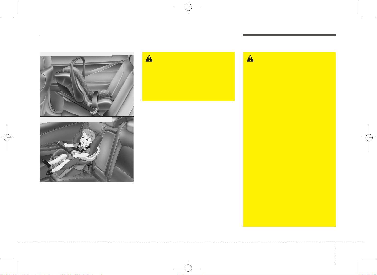
335
Safety features of your vehicle
Using a child restraint system
For small children and babies, the use of
a child seat or infant seat is required. This
child seat or infant seat should be of
appropriate size for the child and should
be installed in accordance with the manu-
facturer's instructions. For safety reasons,
we recommend that the child restraint sys-
tem be used in the rear seats.
WARNING - Child seat
installation
• A child can be seriously injured
or killed in a collision if the child
restraint is not properly anchored
to the vehicle and the child is not
properly restrained in the child
restraint. Before installing the
child restraint system, read the
instructions supplied by the child
restraint system manufacturer.
• If the seat belt does not operate
as described in this section, we
recommend that the system be
checked by an authorized Kia
dealer.
• Failure to observe this manual's
instructions regarding child
restraint system and the instruc-
tions provided with the child
restraint system could increase
the chance and/or severity of
injury in an accident.
• If the vehicle headrest prevents
proper installation of a child seat
(as described in the child seat sys-
tem manual), the headrest of the
respective seating position shall
be readjusted or entirely removed.
WARNING
Never place a rear-facing child
restraint in the front passenger
seat, because of the danger that an
inflating passenger-side air bag
could impact the rear-facing child
restraint and kill the child.
CRS09
OJD032027
Rearward-facing child restraint system
Forward-facing child restraint system
JD PE eng 3.QXP 03.01.2017 16:40 Page 35
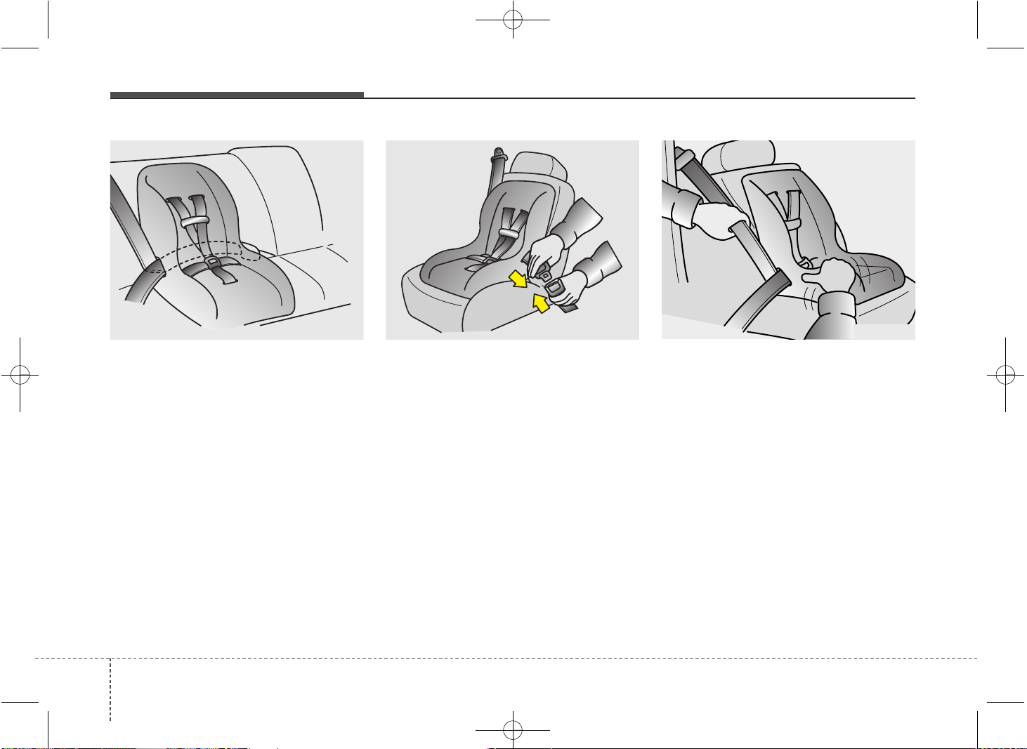
Safety features of your vehicle
363
Installing a child restraint system by
lap/shoulder belt
To install a child restraint system on the
outboard or center rear seats, do the fol-
lowing:
1. Place the child restraint system in the
seat and route the lap/shoulder belt
around or through the restraint, follow-
ing the restraint manufacturer’s
instructions. Be sure the seat belt web-
bing is not twisted.
2. Fasten the lap/shoulder belt latch into
the buckle. Listen for the distinct “click”
sound.
Position the release button so that it is
easy to access in case of an emergency.
3. Buckle the seat belt and allow the seat
belt to take up any slack. After installa-
tion of the child restraint system, try to
move it in all directions to be sure the
child restraint system is securely
installed.
If you need to tighten the belt, pull more
webbing toward the retractor. When you
unbuckle the seat belt and allow it to
retract, the retractor will automatically
revert back to its normal seated passen-
ger emergency locking usage condition.
OEN036101 OEN036104E2MS103005
JD PE eng 3.QXP 03.01.2017 16:40 Page 36
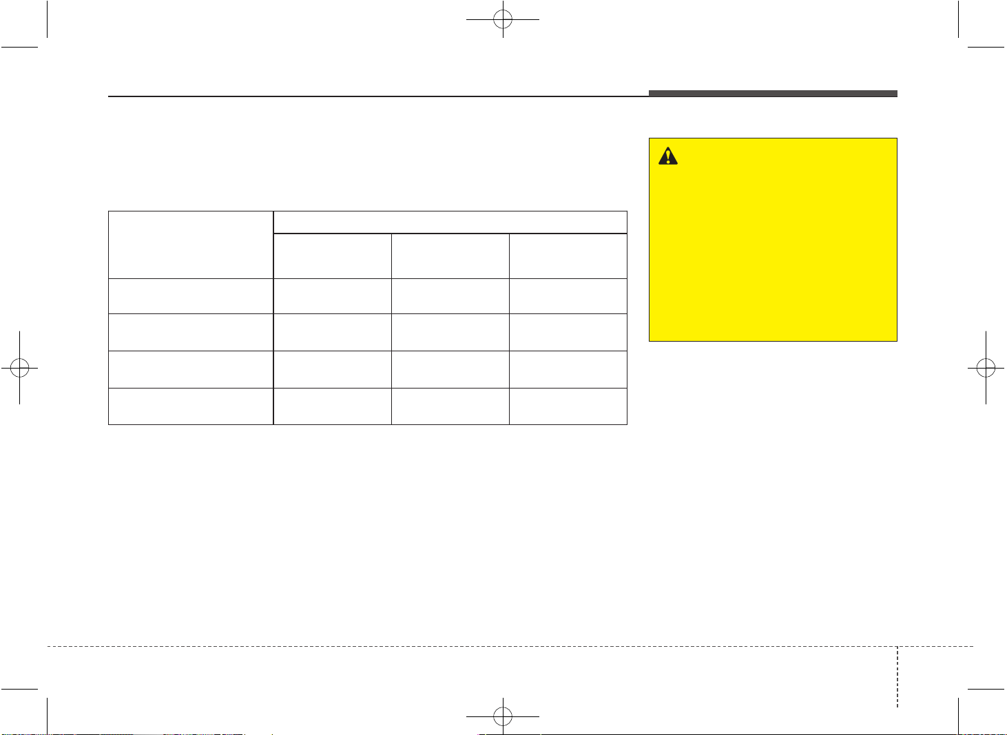
337
Safety features of your vehicle
Child Seat Restraint Suitability for Seat Position using the Seat Belt
- For Europe
Use child safety seats that have been officially approved and are appropriate for your
children. When using the child safety seats, refer to the following table.
Age Group
Seating Position
Front passenger Rear outboard
Rear center
(if equipped)
0 : Up to 10 kg
(0 - 9 months)
U* U U
0+ : Up to 13 kg
(0 - 2 years)
U* U U
I : 9 kg to 18 kg
(9 months - 4 years)
U* U U
II & III : 15 kg to 36 kg
(4 - 12 years)
U* U U
WARNING
We recommend that a child
restraint seat be installed in the
rear seat, even if the front passen-
ger's air bag ON/OFF switch is set
to the OFF position. To ensure the
safety of your child, the front pas-
senger’s air bag must be deactivat-
ed when it should be necessary to
install a child restraint seat on the
front passenger seat in exceptional
circumstances.
U : Suitable for "universal" category restraints approved for use in this mass group
U* : Suitable for "universal" category restraints approved for use just in the condition of
non-height adjustable seat or the highest position of height adjustable seat.
JD PE eng 3.QXP 03.01.2017 16:40 Page 37
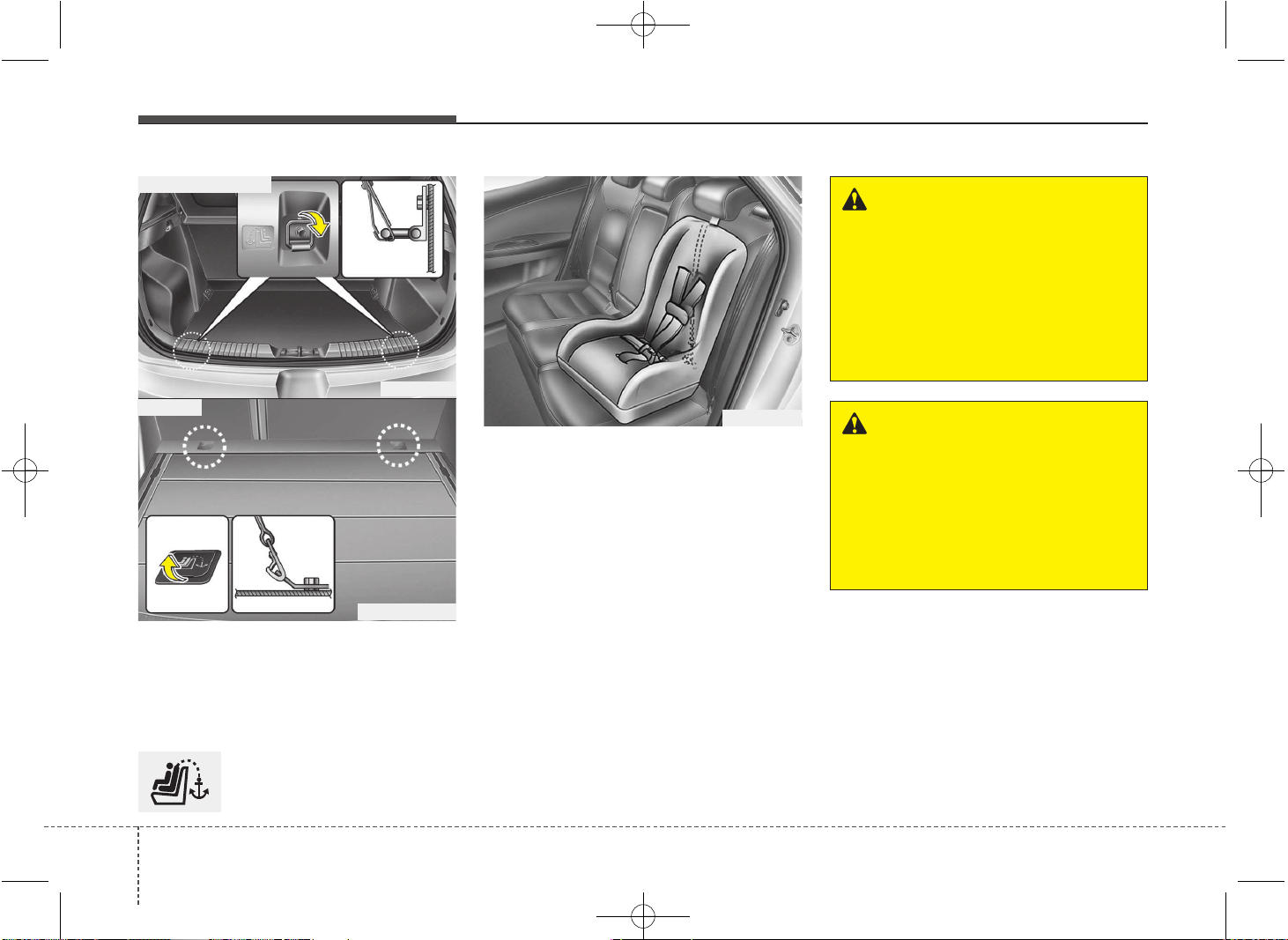
Safety features of your vehicle
383
Securing a child restraint seat with
“Tether Anchor” system (if equipped)
Child restraint hook holders are located
on the transverse trim behind the rear
seats (3 Door and 5 Door) or the floor
behind the rear seats (Wagon).
This symbol indicates the
position of the tether anchor.
1. Route the child restraint seat strap
over the seatback.
For vehicles with adjustable headrest,
route the tether strap under the head-
rest and between the headrest posts,
otherwise route the tether strap over
the top of the seatback.
2. Connect the tether strap hook to the
appropriate child restraint hook holder
and tighten to secure the seat.
OJD032029
WARNING - Tether strap
Never mount more than one child
restraint to a single tether or to a
single lower anchorage point. The
increased load caused by multiple
seats may cause the tethers or
anchorage points to break, causing
serious injury or death.
WARNING
A child can be seriously injured or
killed in a collision if the child
restraint is not properly anchored
to the car and the child is not prop-
erly restrained in the child restraint.
Always follow the child seat manu-
facturer’s instructions for installa-
tion and use.
OJD033028
OGDE032020L
■ 3 Door and 5 Door
■ Wagon
JD PE eng 3.QXP 03.01.2017 16:41 Page 38
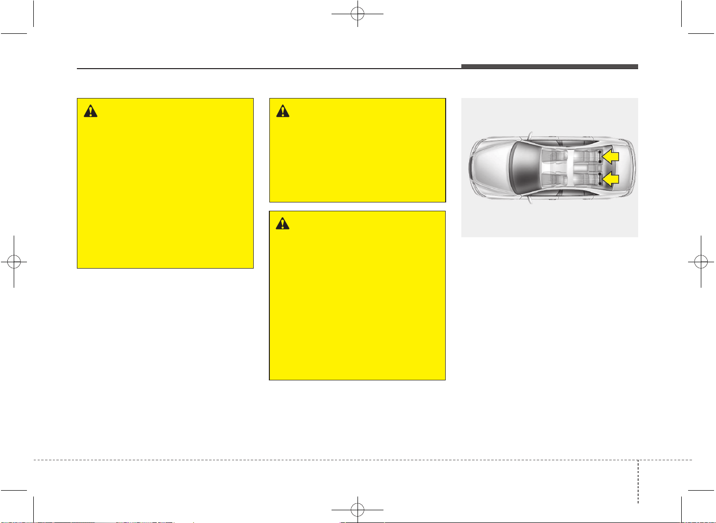
339
Safety features of your vehicle
Securing a child restraint system
with “ISOFIX” system and “Tether
Anchorage” system (if equipped)
ISOFIX is a standardised method of fit-
ting child seats that eliminates the need
to use the standard adult seat belt to
secure the seat in the vehicle. This
enables a much more secure and posi-
tive location with the added benefit of
easier and quicker installation.
An ISOFIX-seat may only be installed if it
has vehicle-specific or universal approval
in accordance with the requirements of
ECE-R 44.
❈ ISOFIX: International Standards Origanisation FIX
OVI039060
WARNING - Child restraint
check
Check that the child restraint sys-
tem is secure by pushing and
pulling it in different directions.
Incorrectly fitted child restraints
may swing, twist, tip or separate
causing death or serious injury.
WARNING
- Child restraint anchorage
• Child restraint anchorages are
designed to withstand only those
loads imposed by correctly fitted
child restraints. Under no circum-
stances are they to be used for
adult seat belts or harnesses or
for attaching other items or
equipment to the vehicle.
• The tether strap may not work
properly if attached somewhere
other than the correct tether
anchor.
WARNING
Do not install a child restraint seat
at the center of the rear seat using
the tether anchors. The tether
anchors are only provided for the
left and right outboard rear seating
positions.
In a crash, the child restraint seat
tether anchor attachments may not
be strong enough to secure the
child restraint seat properly in the
center of the rear seat and may
break, causing serious injury or
death.
JD PE eng 3.QXP 03.01.2017 16:41 Page 39
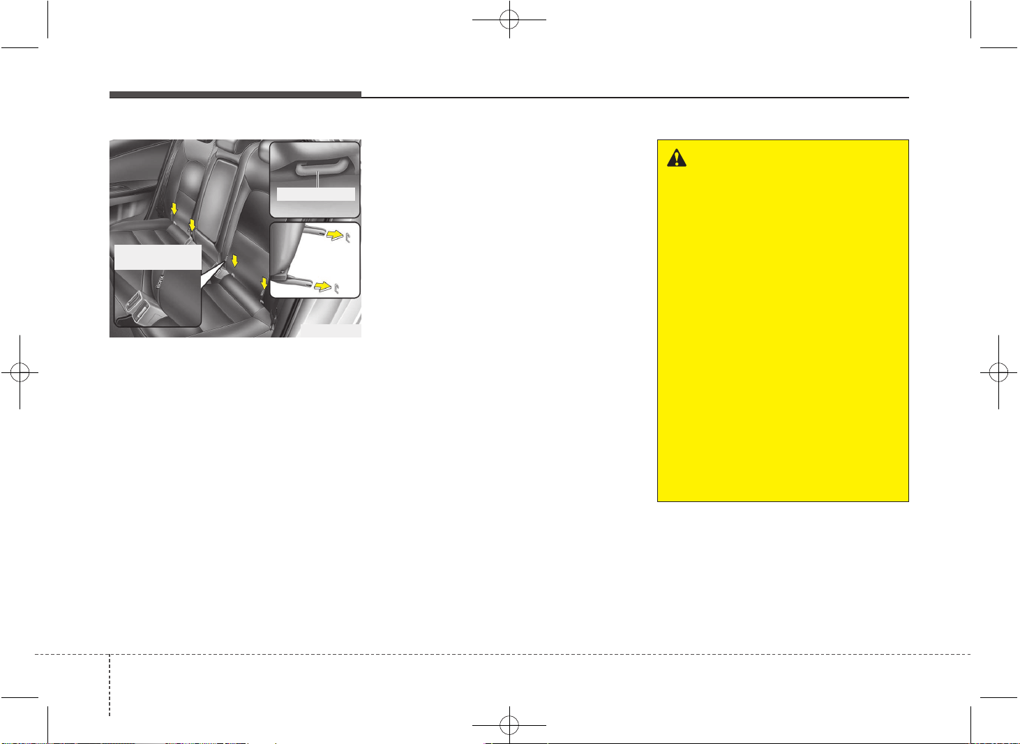
Safety features of your vehicle
403
There are ISOFIX symbols located on
the lower portion of each side of the rear
seatbacks. These symbols indicate the
position of the lower anchors for child
restraints so equipped.
Both rear outboard seats are equipped
with a pair of ISOFIX anchorages as well
as a corresponding top tether anchorage
on the floor behind the rear seats
(wagon) or the shelf behind the rear
seats (sedan). The ISOFIX anchorages
are located between seat cushion and
backrest, marked with the ISOFIX icon.
For installation, CRS ISOFIX connecters
have to engage with the vehicles ISOFIX
anchorages (listen for a CLICK, check
potential visual indicators on the CRS
and cross-check by pulling).
CRS with universal approval to ECE-R
44 need to be fixed additionally with a top
tether strap connected to the correspon-
ding top tether anchorage point on the
floor behind the rear seats (wagon) or the
shelf behind the rear seats (sedan).
The installing and the use of a child-seat
has to be done according to the
installing-manual, which is added to the
ISOFIX-seat.
WARNING
• When using the vehicle's
"ISOFIX" system to install a child
restraint system in the rear seat,
all unused vehicle rear seat belt
metal latch plates or tabs must be
latched securely in their seat belt
buckles and the seat belt web-
bing must be retracted behind
the child restraint to prevent the
child from reaching and taking
hold of unretracted seat belts.
Unlatched metal latch plates or
tabs may allow the child to reach
the unretracted seat belts which
may result in strangulation and a
serious injury or death to the
child in the child restraint.
• Do not place anything around the
ISOFIX anchors. Also make sure
that the seat belt is not caught in
the ISOFIX anchors.
OJD032030
ISOFIX Anchor
ISOFIX Anchor
Position Indicator
JD PE eng 3.QXP 03.01.2017 16:41 Page 40
341
Safety features of your vehicle
To secure the child restraint seat
1. To engage the child restraint seat to
the ISOFIX anchor, insert the child
restraint seat latch into the ISOFIX
anchor. Listen for the audible “click”
sound.
2. Connect the tether strap hook to the
child restraint hook holder and tighten
to secure the seat. (Refer to the previ-
ous page.)
(Continued)
• Attach the ISOFIX or ISOFIX-com-
patible child restraint seat only to
the appropriate locations shown
in the illustration.
• Always follow the installation and
use instructions provided by the
manufacturer of the child restraint.
WARNING
• Do not install a child restraint seat
at the center of the rear seat using
the vehicle's ISOFIX anchors. The
ISOFIX anchors are only provided
for the left and right outboard rear
seating positions. Do not misuse
the ISOFIX anchors by attempting
to attach a child restraint seat in
the middle of the rear seat to the
ISOFIX anchors.
In a crash, the child restraint seat
ISOFIX attachments may not be
strong enough to secure the child
restraint seat properly in the cen-
ter of the rear seat and may break,
causing serious injury or death.
• Do not mount more than one
child restraint to a child restraint
lower anchorage point. The
improper increased load may
cause the anchorage points or
tether anchor to break, causing
serious injury or death.
(Continued)
CAUTION
Do not allow the rear seat belt web-
bing to get scratched or pinched by
the ISOFIX-seat latch and ISOFIX
anchor during installation.
JD PE eng 3.QXP 03.01.2017 16:41 Page 41
Safety features of your vehicle
423
Child seat restraint suitability for vehicle ISOFIX positions - For Europe
F ISO/L1 - X X -
G ISO/L2 - X X -
E ISO/R1 - IL IL -
E ISO/R1 - IL IL -
D ISO/R2 - IL IL -
C ISO/R3 - IL* IL* -
D ISO/R2 - IL IL -
C ISO/R3 - IL* IL* -
B ISO/F2 - IUF IUF -
B1 ISO/F2X - IUF IUF -
A ISO/F3 - IUF IUF -
Rear Outboard
(Passenger side)
Rear Outboard
(Driver side)
Front Passenger
FixtureSize Class
Mass Group
Carrycot
0 : UP to 10kg
0+ : UP to 13kg
I : 9 to 18kg
Rear Center
Vehicle ISOFIX positions
IUF = Suitable for ISOFIX forward child restraints systems of universal category approved for use in the mass group.
IL = Suitable for particular ISOFIX child restraints systems (CRS) given in the attached list. These ISOFIX CRS are those of the
"specific vehicle", "restricted" or "semi-universal" categories.
X = ISOFIX position not suitable for ISOFIX child restraint system in this mass group and/or this size class.
IL* = ISO/R3 is able to be set up only at the foremost position of the front seats.
But ISO/R3 is not able to be set up for 3 door vehicle.
JD PE eng 3.QXP 03.01.2017 16:41 Page 42
343
Safety features of your vehicle
Recommended child restraint systems – For Europe
CRS Manufacturer information
Britax Römer http://www.britax.com
Mass Group
Name
Part. No.
Manufacturer Type of Fixation
ECE-R44
Approval No.
Group 0+
(0-13kg)
Baby Safe Plus
Part. No. E8945-66001
Part. No. E8945-66029
Britax Römer Rearward facing with ISOFIX adapter E1 04301146
Group 1
(9-18kg)
Duo Plus
Part. No. E8945-66011
Britax Römer
Forward facing with vehicle
ISOFIX lower anchorage + Top Tether
E1 04301133
Forward facing with vehicle
3-point seat belt
JD PE eng 3.QXP 03.01.2017 16:41 Page 43
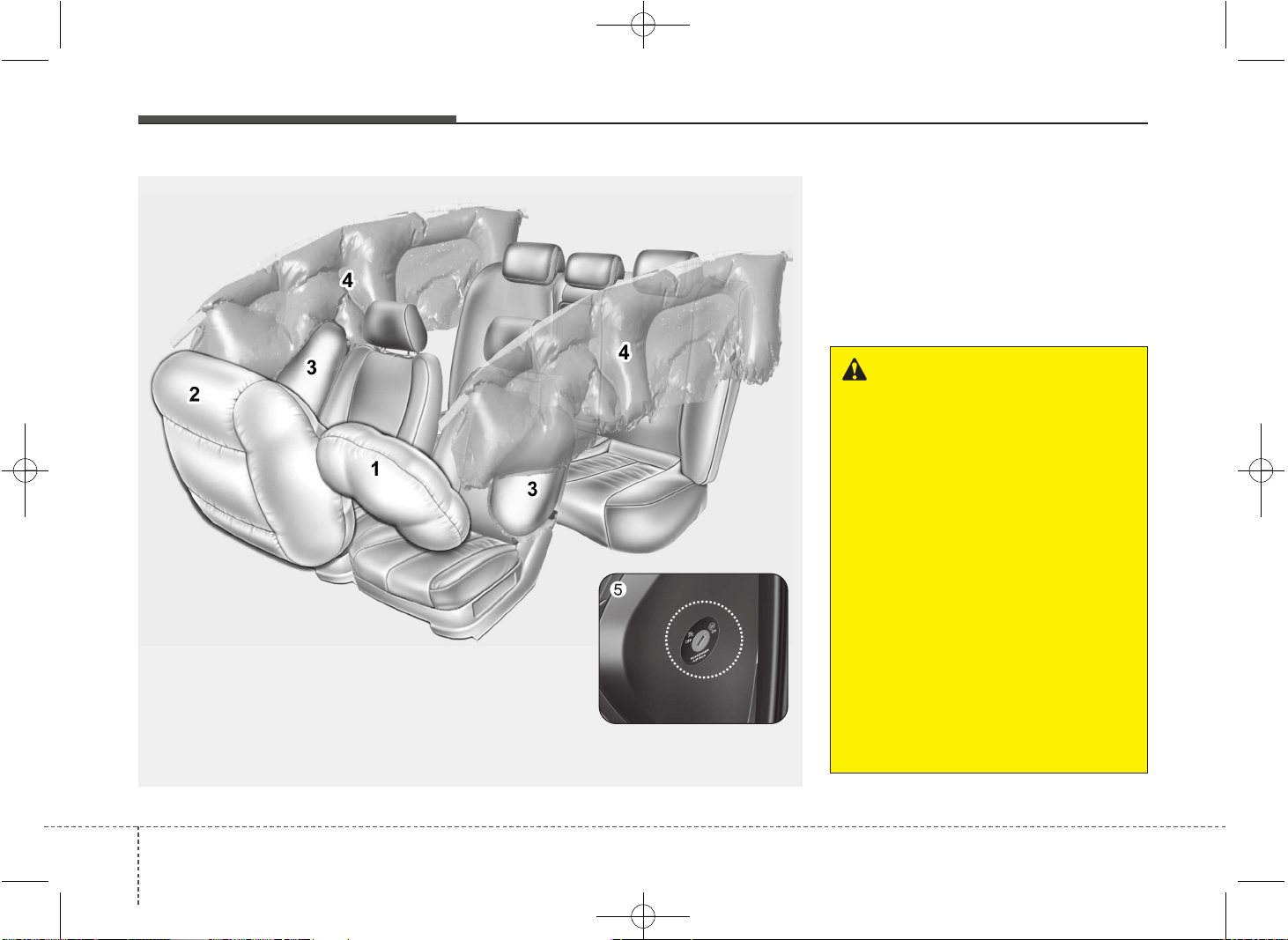
Safety features of your vehicle
443
(1) Driver’s front air bag
(2) Passenger’s front air bag
(3) Side impact air bag*
(4) Curtain air bag*
(5) Passenger’s front air bag ON/OFF
switch
* : if equipped
AIR BAG - SUPPLEMENTAL RESTRAINT SYSTEM (IF EQUIPPED)
OJD032031/OJD032032
❈ The actual air bags in the vehicle may differ from the illustration.
WARNING
• Even in vehicles with air bags,
you and your passengers must
always wear the safety belts pro-
vided in order to minimize the
risk and severity of injury in the
event of a collision or rollover.
• SRS and pretensioners contain
explosive chemicals.
If scraping a vehicle without
removing SRS and pretensioners
from a vehicle, it may cause fire.
Before scraping a vehicle, we rec-
ommend that you contact an
authorized Kia dealer.
• Keep the SRS parts and wirings
away from water or any liquid. If the
SRS components are inoperative
due to exposure to water or liquids,
it may cause fire or severe injury.
JD PE eng 3.QXP 03.01.2017 16:41 Page 44
345
Safety features of your vehicle
How does the air bag system
operate
• Air bags are activated (able to inflate if
necessary) only when the ignition
switch is turned to the ON or START
position.
• Air bags inflate instantly in the event of
serious frontal or side collision (if
equipped with side impact air bag or
curtain air bag) in order to help protect
the occupants from serious physical
injury.
• There is no single speed at which the
air bags will inflate.
Generally, air bags are designed to
inflate based upon the severity of a col-
lision and its direction. These two fac-
tors determine whether the sensors
produce an electronic deployment/
inflation signal.
• Air bag deployment depends on a
number of factors including vehicle
speed, angles of impact and the densi-
ty and stiffness of the vehicles or
objects which your vehicle hits in the
collision. The determining, factors are
not limited to those mentioned above.
• The front air bags will completely
inflate and deflate in an instant.
It is virtually impossible for you to see
the air bags inflate during an accident.
It is much more likely that you will sim-
ply see the deflated air bags hanging
out of their storage compartments after
the collision.
• In order to help provide protection in a
severe collision, the air bags must
inflate rapidly. The speed of air bag infla-
tion is a consequence of extremely
short time in which a collision occurs
and the need to get the air bag between
the occupant and the vehicle structures
before the occupant impacts those
structures. This speed of inflation
reduces the risk of serious or life-threat-
ening injuries in a severe collision and is
thus a necessary part of air bag design.
However, air bag inflation can also
cause injuries which can include facial
abrasions, bruises and broken bones
because the inflation speed also caus-
es the air bags to expand with a great
deal of force.
• There are even circumstances
under which contact with the steer-
ing wheel air bag can cause fatal
injuries, especially if the occupant
is positioned excessively close to
the steering wheel.
WARNING
• To avoid severe personal injury
or death caused by deploying air
bags in a collision, the driver
should sit as far back from the
steering wheel air bag as possible
(at least 250 mm (10 inches)
away).The front passenger should
always move their seat as far
back as possible and sit back in
their seat.
• Air bag inflates instantly in an
event of a collision, passengers
may be injured by the air bag
expansion force if they are not in
a proper position.
• Air bag inflation may cause
injuries including facial or bodily
abrasions, injuries from broken
glasses or burns.
JD PE eng 3.QXP 03.01.2017 16:41 Page 45
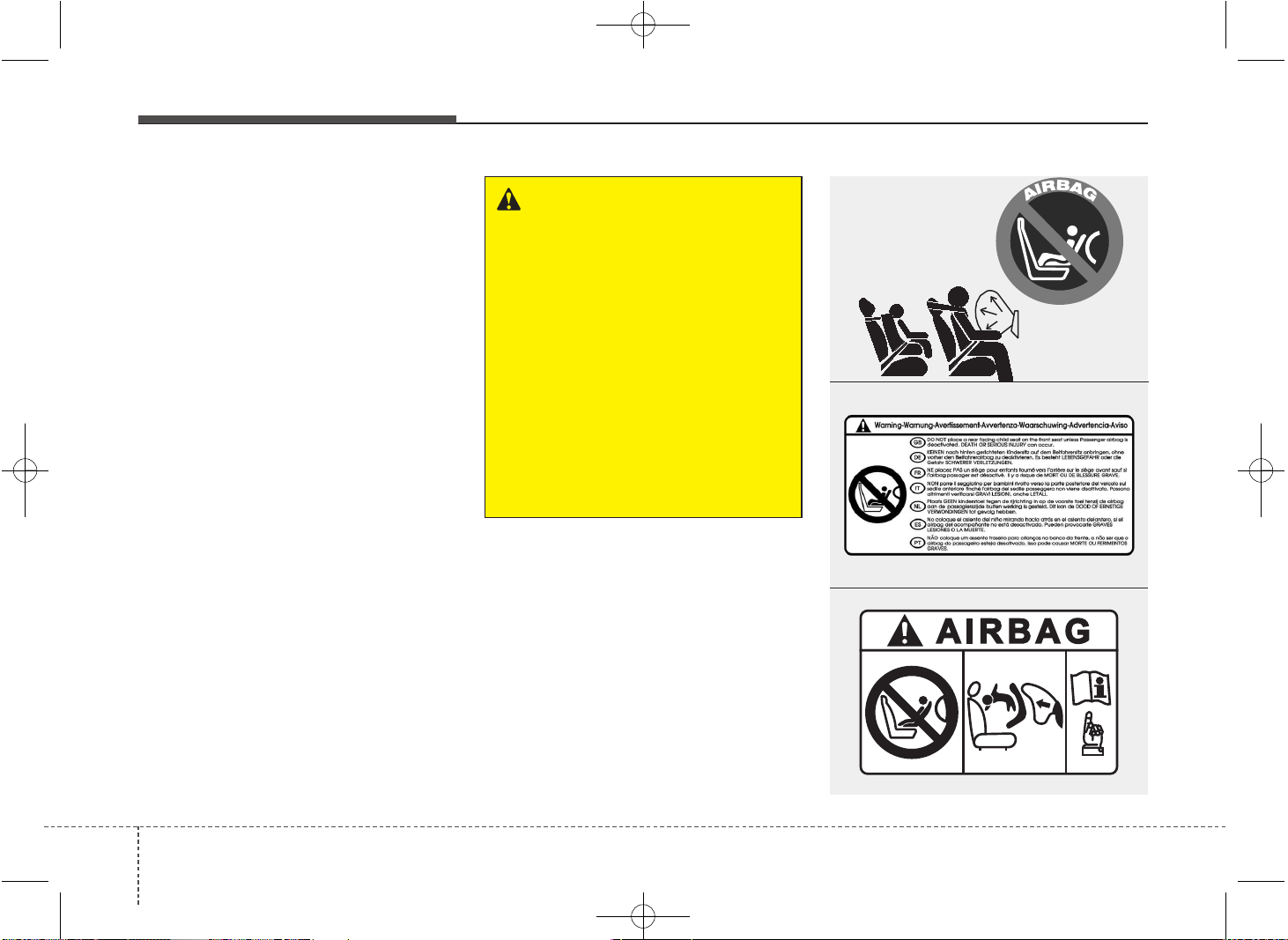
Safety features of your vehicle
463
Noise and smoke
When the air bags inflate, they make a loud
noise and they leave smoke and powder in
the air inside of the vehicle. This is normal
and is a result of the ignition of the air bag
inflator. After the air bag inflates, you may
feel substantial discomfort in breathing due
to the contact of your chest with both the
seat belt and the air bag, as well as from
breathing the smoke and powder. Open
your doors and/or windows as soon as
possible after impact in order to reduce
discomfort and prevent prolonged
exposure to the smoke and powder.
Though smoke and powder are non-
toxic, it may cause irritation to the skin
(eyes, nose and throat, etc.). If this is the
case, wash and rinse with cold water
immediately and consult the doctor if the
symptom persists.
WARNING
• When the air bags deploy, the air
bag related parts in the steering
wheel and/or instrument panel
and/or in both sides of the roof
rails above the front and rear
doors are very hot. To prevent
injury, do not touch the air bag
storage areas internal compo-
nents immediately after an air
bag has inflated.
• Do not install or place any acces-
sories near air bag deployment
areas, such as the instrument
panel, windows, pillars, and roof
rails.
OYDESA2042
1JBH3051
■ Type B
■ Type A
OJD032059
JD PE eng 3.QXP 03.01.2017 16:41 Page 46
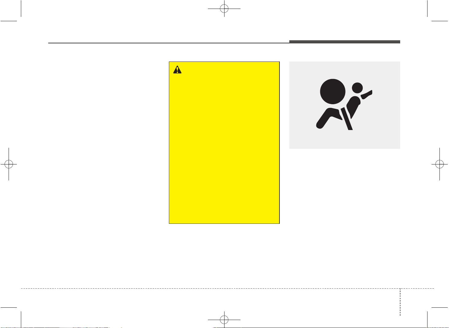
347
Safety features of your vehicle
Do not install a child restraint on the
front passenger’s seat
Never place a rear-facing child restraint
in the front passenger’s seat. If the air
bag deploys, it would impact the rear-fac-
ing child restraint, causing serious or
fatal injury.
In addition, do not place front-facing child
restraints in the front passenger’s seat
either. If the front passenger air bag
inflates, it would cause serious or fatal
injuries to the child.
If your vehicle is equipped with the pas-
senger’s front air bag ON/OFF switch,
you can activate or deactivate the front
passenger’s air bag when necessary.
For more details, please refer to 3-52 page.
Air bag warning and indicator
Air bag warning light
The purpose of the air bag warning light
in your instrument panel is to alert you of
a potential problem with your air bag -
Supplemental Restraint System (SRS).
WARNING
• NEVER use a rearward facing
child restraint on a seat protected
by an ACTIVE AIRBAG in front of
it, DEATH or SERIOUS INJURY to
the CHILD can occur.
• Never put a child restraint in the
front passenger’s seat. If the front
passenger air bag inflates, it
would cause serious or fatal
injuries.
• When children are seated in the
rear outboard seats of vehicle
equipped with curtain air bags,
be sure to install the child
restraint system as far away from
the door side as possible, and
securely lock the child restraint
system in position.
Inflation of curtain air bags could
cause serious injury or death to
an infant or child.
W7-147
JD PE eng 3.QXP 03.01.2017 16:41 Page 47
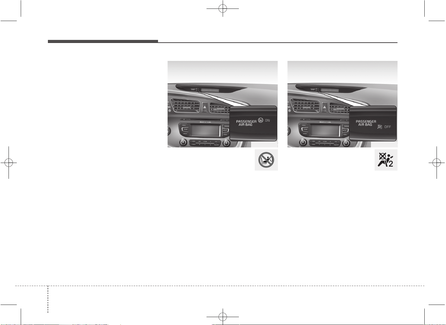
Safety features of your vehicle
483
When the ignition switch is turned ON,
the warning light should illuminate for
approximately 6 seconds, then go off.
Have the system checked if:
• The light does not turn on briefly when
you turn the ignition ON.
• The light stays on after illuminating for
approximately 6 seconds.
• The light comes on while the vehicle is
in motion.
• The light blinks when the ignition
switch is in ON position.
Passenger’s front air bag
ON indicator
The passenger's front air bag ON indica-
tor illuminates for approximately 4 sec-
onds after the ignition switch is turned to
the ON position.
The passenger's front air bag ON indica-
tor also comes on when the passenger's
front air bag ON/OFF switch is set to the
ON position and goes off after approxi-
mately 60 seconds.
Passenger’s front air bag
OFF indicator
The passenger’s front air bag OFF indi-
cator illuminates for about 4 seconds
after the ignition switch is turned to the
ON position.
The passenger’s front air bag OFF indi-
cator also comes on when the passen-
ger’s front air bag ON/OFF switch is set
to the OFF position and goes off when
the passenger’s front air bag ON/OFF
switch is set to the ON position.
OJD032033 OJD032034
JD PE eng 3.QXP 03.01.2017 16:41 Page 48
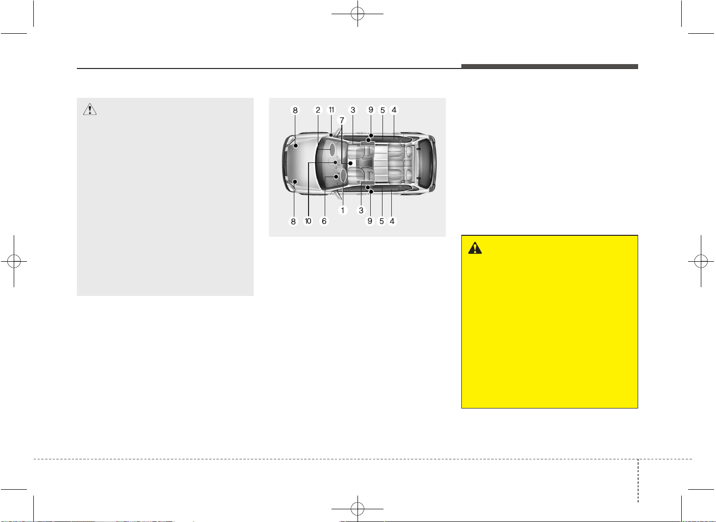
349
Safety features of your vehicle
SRS components and functions
The SRS consists of the following com-
ponents:
1. Driver's front air bag module
2. Passenger's front air bag module
3. Side air bag modules*
4. Curtain air bag modules*
5. Retractor pre-tensioner assemblies
6. Air bag warning light
7. SRS control module (SRSCM)
8. Front impact sensors
9. Side impact sensors*
10. Passenger’s front air bag ON/OFF
indicator
11. Passenger’s front air bag ON/OFF
switch
* : if equipped
The SRSCM continually monitors all ele-
ments while the ignition switch is ON to
determine if a frontal, near-frontal impact
or side impact is severe enough to require
air bag deployment or pre-tensioner seat
belt deployment.
The SRS air bag warning light on the
instrument panel will illuminate for about
6 seconds after the ignition switch is
turned to the ON position, after which the
air bag warning light should go out.
WARNING
If any of the following conditions
occurs, this indicates a malfunction
of the SRS. We recommend that the
system be inspected by an author-
ized Kia dealer.
• The light does not turn on briefly
when you turn the ignition ON.
• The light stays on after illuminat-
ing for approximately 6 seconds.
• The light comes on while the
vehicle is in motion.
• The light blinks when the ignition
switch is in ON position.
OJD032053
CAUTION
If the passenger’s front air bag
ON/OFF switch malfunctions, the
passenger’s front air bag OFF indi-
cator will not illuminate (The pas-
senger's front air bag ON indicator
comes on and goes off after
approximately 60 seconds) and the
passenger’s front air bag will inflate
in a frontal impact even if the pas-
senger’s front air bag ON/OFF
switch is set to the OFF position.
If this occurs, we recommend that
the passenger’s front air bag
ON/OFF switch and the SRS air bag
system be inspected by an author-
ized Kia dealer.
JD PE eng 3.QXP 03.01.2017 16:41 Page 49
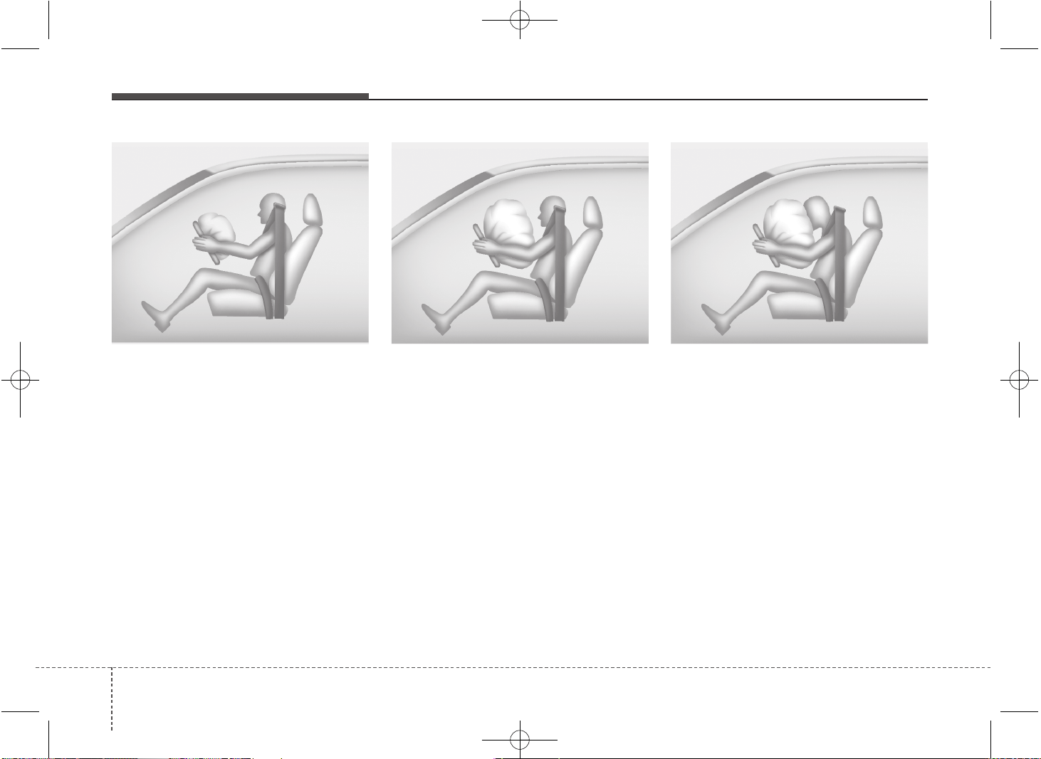
Safety features of your vehicle
503
The air bag modules are located both in
the center of the steering wheel and in
the front passenger's panel above the
glove box. When the SRSCM detects a
sufficiently severe impact to the front of
the vehicle, it will automatically deploy
the front air bags.
Upon deployment, tear seams molded
directly into the pad covers will separate
under pressure from the expansion of the
air bags. Further opening of the covers
then allows full inflation of the air bags.
A fully inflated air bag, in combination
with a properly worn seat belt, slows the
driver's or the passenger's forward
motion, reducing the risk of head and
chest injury.
After complete inflation, the air bag
immediately starts deflating, enabling the
driver to maintain forward visibility and
the ability to steer or operate other con-
trols.
B240B02L B240B03L
Driver’s front air bag (2) Driver’s front air bag (3)
B240B01L
Driver’s front air bag (1)
JD PE eng 3.QXP 03.01.2017 16:41 Page 50
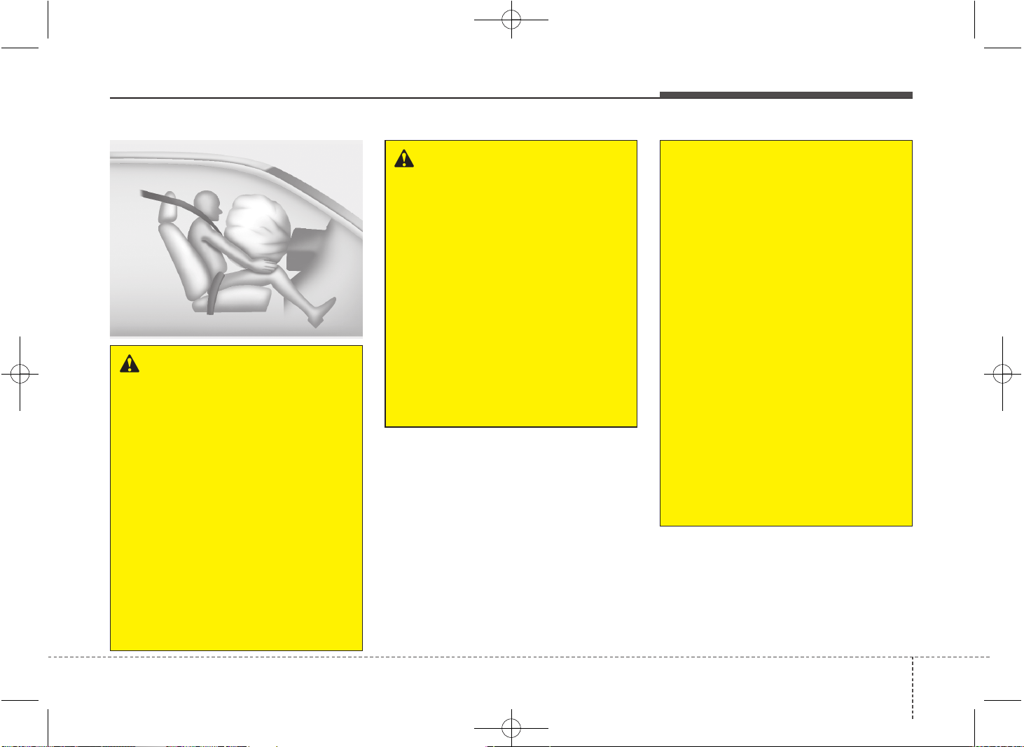
351
Safety features of your vehicle
WARNING
• If an air bag deploys, there may
be a loud noise followed by a fine
dust released in the vehicle.
These conditions are normal and
are not hazardous - the air bags
are packed in this fine powder.
The dust generated during air
bag deployment may cause skin
or eye irritation as well as aggra-
vate asthma for some persons.
Always wash all exposed skin
areas thoroughly with cold water
and a mild soap after an accident
in which the air bags were
deployed.
(Continued)
(Continued)
• The SRS can function only when
the ignition key is in the ON posi-
tion. If the SRS air bag warning
light does not illuminate, or con-
tinuously remains on after illumi-
nating for about 6 seconds when
the ignition key is turned to the
ON position, or after the engine is
started, comes on while driving,
the SRS is not working properly.
If this occurs, we recommend
that the system be inspected by
an authorized Kia dealer.
• Before you replace a fuse or dis-
connect a battery terminal, turn
the ignition switch to the LOCK
position and remove the ignition
key. Never remove or replace the
air bag related fuse(s) when the
ignition switch is in the ON posi-
tion. Failure to heed this warning
will cause the SRS air bag warn-
ing light to illuminate.
WARNING
• Do not install or place any acces-
sories (drink holder, cassette
holder, sticker, etc.) on the front
passenger's panel above the
glove box in a vehicle with a pas-
senger's air bag. Such objects
may become dangerous projec-
tiles and cause injury if the pas-
senger's air bag inflates.
• When installing a container of liq-
uid air freshener inside the vehi-
cle, do not place it near the
instrument cluster nor on the
instrument panel surface.
It may become dangerous projec-
tiles and cause injury if the pas-
senger's air bag inflates.
B240B05L
Passenger’s front air bag
JD PE eng 3.QXP 03.01.2017 16:41 Page 51
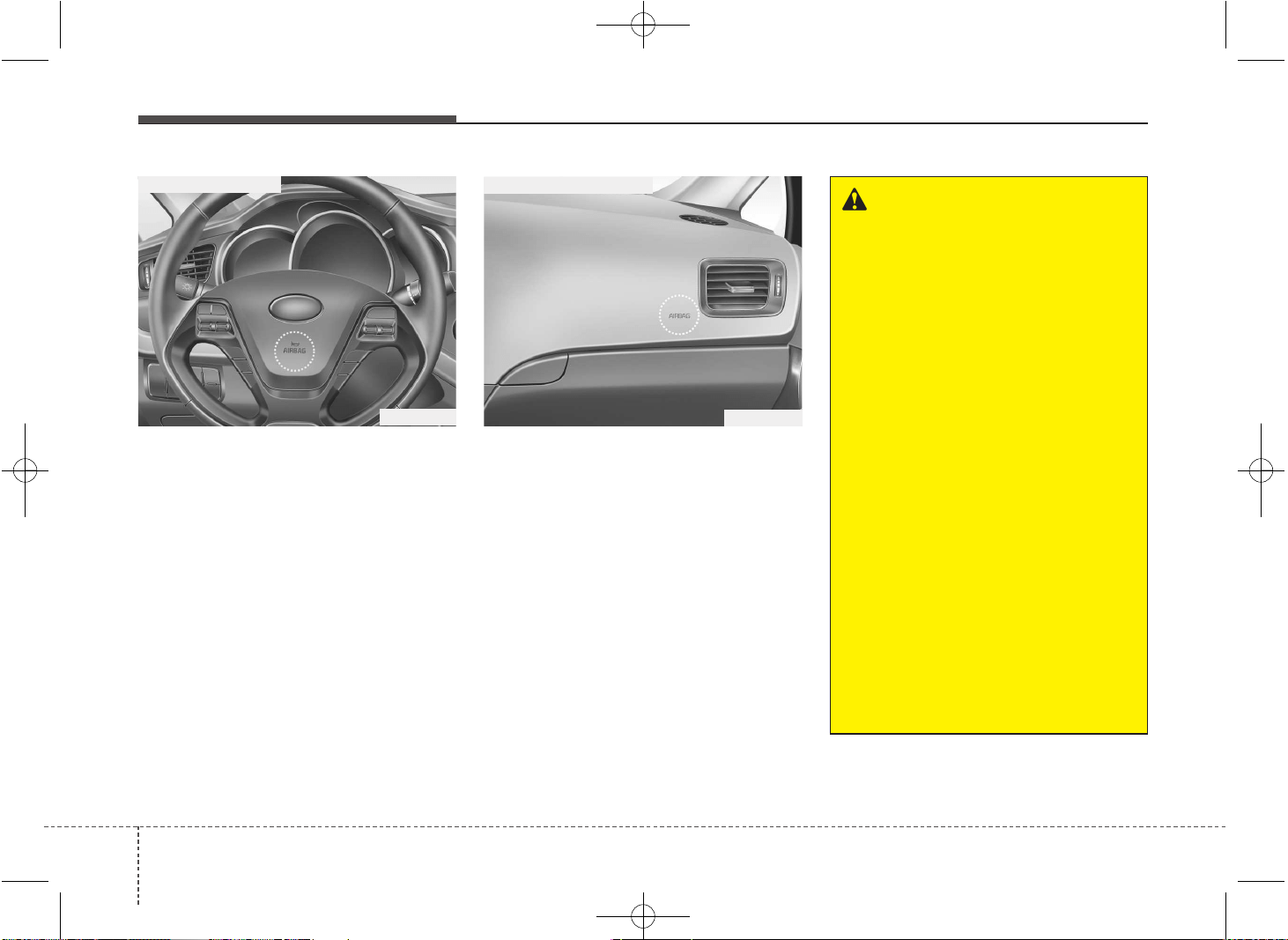
Safety features of your vehicle
523
Driver's and passenger's front air
bag
Your vehicle is equipped with a
Supplemental Restraint (Air Bag) System
and lap/shoulder belts at both the driver
and passenger seating positions.
The indications of the system's presence
are the letters "AIR BAG" embossed on
the air bag pad cover in the steering
wheel and the passenger's side front
panel pad above the glove box.
The SRS consists of air bags installed
under the pad covers in the center of the
steering wheel and the passenger's side
front panel above the glove box.
The purpose of the SRS is to provide the
vehicle's driver and/or the front passen-
ger with additional protection than that
offered by the seat belt system alone in
case of a frontal impact of sufficient
severity.
OJD032036
■ Passenger’s front air bag
OJD032035
■ Driver’s front air bag
WARNING
Always use seat belts and child
restraints – every trip, every time,
everyone! Air bags inflate with con-
siderable force and in the blink of an
eye. Seat belts help keep occupants
in proper position to obtain maxi-
mum benefit from the air bag. Even
with air bags, improperly and unbelt-
ed occupants can be severely
injured when the air bag inflates.
Always follow the precautions about
seat belts, air bags and occupant
safety contained in this manual.
To reduce the chance of serious or
fatal injuries and receive the maxi-
mum safety benefit from your
restraint system:
• Never place a child in any child or
booster seat in the front seat.
• ABC – Always Buckle Children in
the back seat. It is the safest place
for children of any age to ride.
• Front and side impact air bags
can injure occupants improperly
positioned in the front seats.
(Continued)
JD PE eng 3.QXP 03.01.2017 16:41 Page 52
353
Safety features of your vehicle
(Continued)
• Do not tamper with or disconnect
SRS wiring or other components
of the SRS system. Doing so
could result in injury, due to acci-
dental deployment of the air bags
or by rendering the SRS inopera-
tive.
• If the SRS air bag warning light
remains illuminated while the
vehicle is being driven, we rec-
ommend that the system be
inspected by an authorized Kia
dealer.
• Air bags can only be used once –
we recommend that the system
be replaced by an authorized Kia
dealer.
• The SRS is designed to deploy
the front air bags only when an
impact is sufficiently severe and
when the impact angle is less
than 30° from the forward longitu-
dinal axis of the vehicle.
Additionally, the air bags will only
deploy once. Seat belts must be
worn at all times.
(Continued)
(Continued)
• Move your seat as far back as
practical from the front air bags,
while still maintaining control of
the vehicle.
• You and your passengers should
never sit or lean unnecessarily
close to the air bags. Improperly
positioned drivers and passen-
gers can be severely injured by
inflating air bags.
• Never lean against the door or
center console – always sit in an
upright position.
• No objects should be placed over
or near the air bag modules on
the steering wheel, instrument
panel, and the front passenger's
panel above the glove box,
because any such object could
cause harm if the vehicle is in a
crash severe enough to cause
the air bags to deploy.
(Continued)
(Continued)
• Front air bags are not intended to
deploy in side-impact, rear-
impact or rollover crashes. In
addition, front air bags will not
deploy in frontal crashes below
the deployment threshold.
• A child restraint system must
never be placed in the front seat.
The infant or child could be
severely injured or killed by an air
bag deployment in case of an
accident.
• Children age 12 and under must
always be properly restrained in
the rear seat. Never allow chil-
dren to ride in the front passen-
ger seat. If a child over 12 must
be seated in the front seat, he or
she must be properly belted and
the seat should be moved as far
back as possible.
(Continued)
JD PE eng 3.QXP 03.01.2017 16:41 Page 53
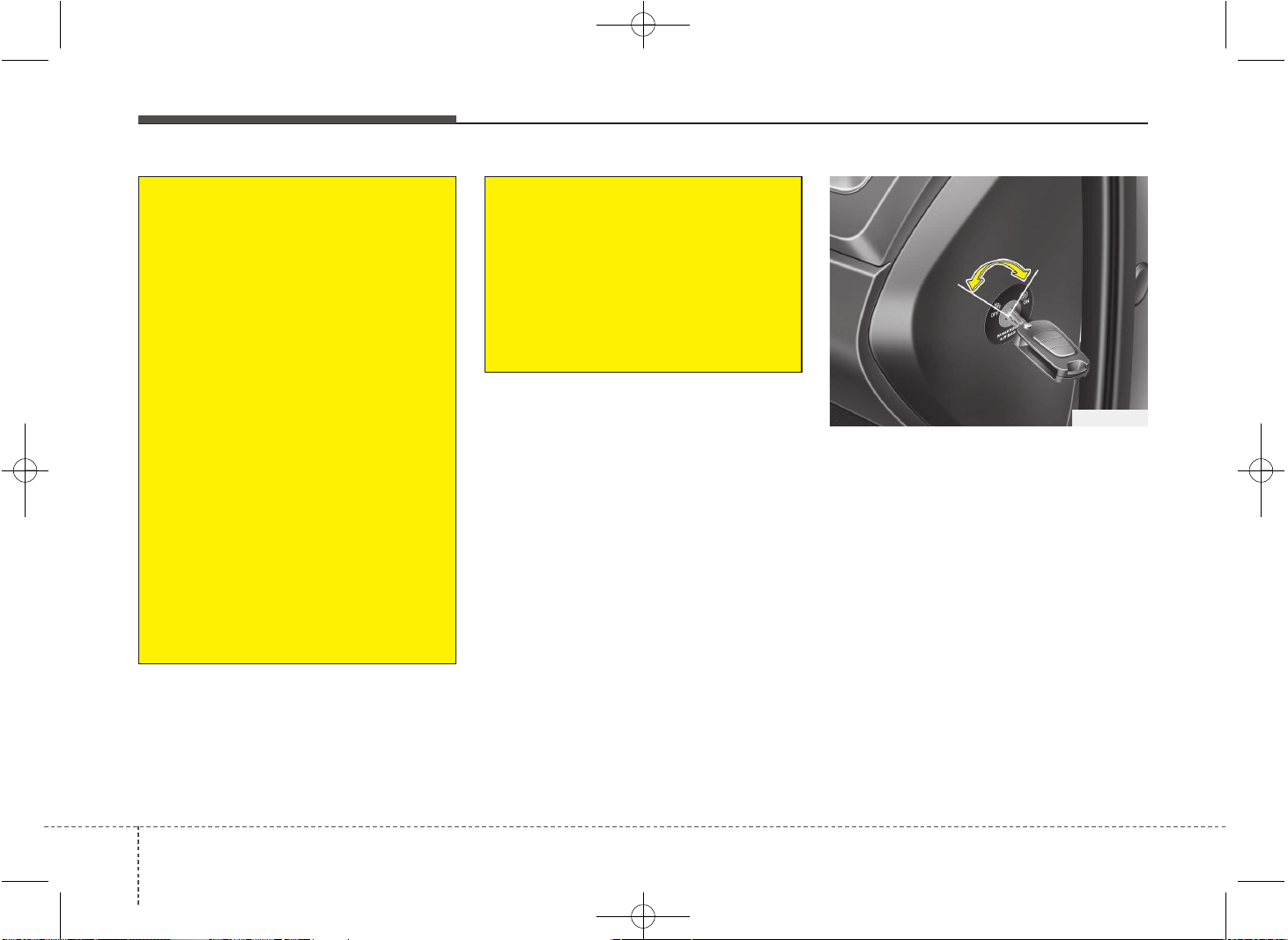
Safety features of your vehicle
543
Passenger’s front air bag ON/OFF
switch (if equipped)
The passenger’s front air bag can be
deactivated by the passenger’s front air
bag ON/OFF switch if a child restraint is
installed on the front passenger's seat or
if the front passenger's seat is unoccu-
pied by a person.
To ensure the safety of your child, the
passenger’s front air bag must be deacti-
vated when it should be necessary to
install a rearward facing child seat on the
front passenger seat in exceptional cir-
cumstances.
OJD032037
(Continued)
• For maximum safety protection in
all types of crashes, all occu-
pants including the driver should
always wear their seat belts
whether or not an air bag is also
provided at their seating position
to minimize the risk of severe
injury or death in the event of a
crash. Do not sit or lean unneces-
sarily close to the air bag while
the vehicle is in motion.
• Sitting improperly or out of posi-
tion can result in serious or fatal
injury in a crash. All occupants
should sit upright with the seat
back in an upright position, cen-
tered on the seat cushion with
their seat belt on, legs comfort-
ably extended and their feet on
the floor until the vehicle is
parked and the ignition key is
removed.
(Continued)
(Continued)
• The SRS air bag system must
deploy very rapidly to provide
protection in a crash. If an occu-
pant is out of position because of
not wearing a seat belt, the air
bag may forcefully contact the
occupant causing serious or fatal
injuries.
JD PE eng 3.QXP 03.01.2017 16:41 Page 54
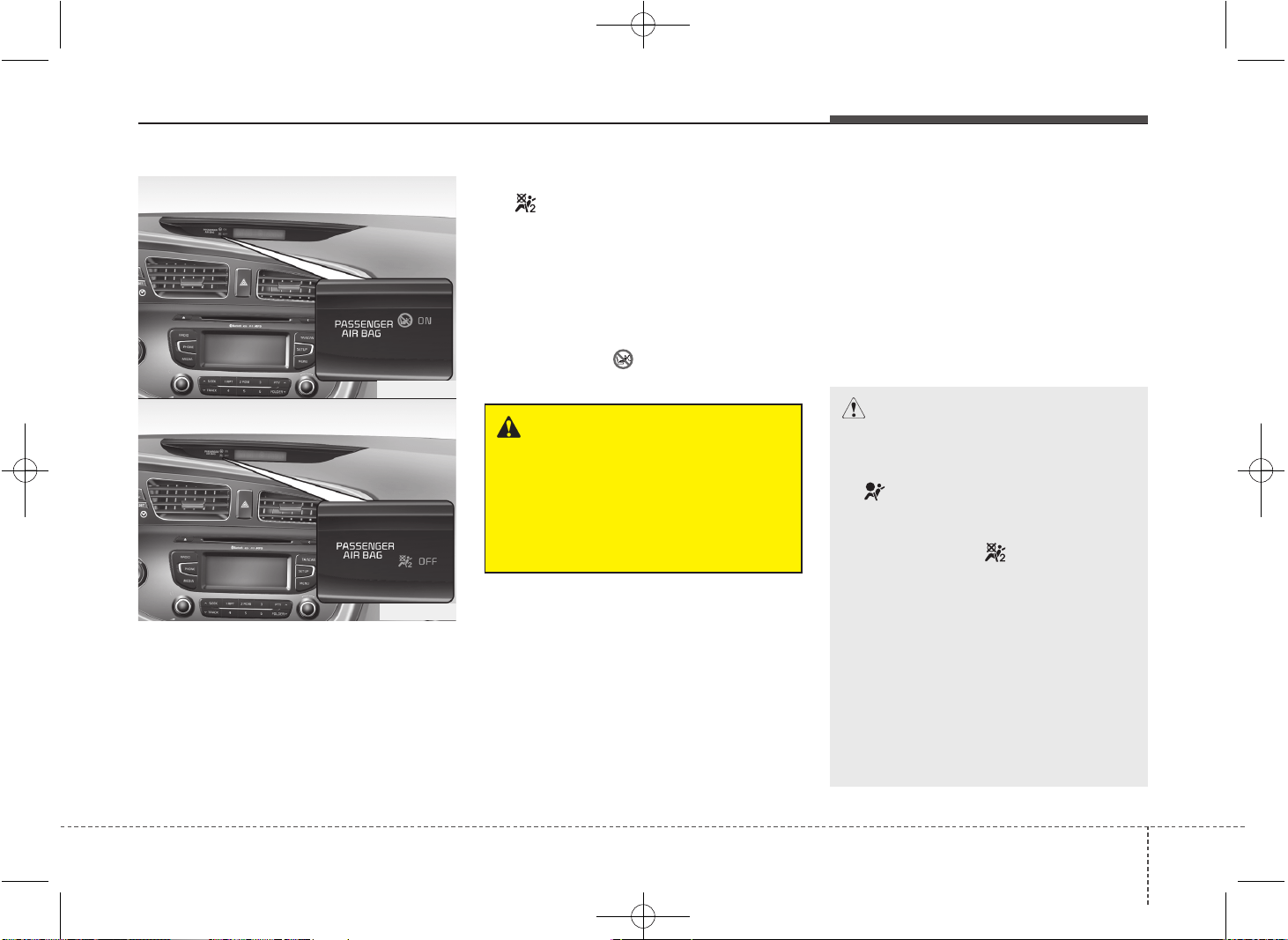
355
Safety features of your vehicle
To deactivate or reactivate the passen-
ger’s front air bag:
To deactivate the passenger’s front air
bag, insert the mechanical key into the
passenger’s front air bag ON/OFF switch
and turn it to the OFF position.
The passenger’s front air bag OFF indica-
tor ( ) will illuminate and stay on until the
passenger’s front air bag is reactivated.
To reactivate the passenger’s front air
bag, insert the mechanical key into the
passenger’s front air bag ON/OFF switch
and turn it to the ON position. The pas-
senger’s front air bag OFF indicator will
go out and the passenger’s front air bag
ON indicator ( ) will illuminate for
approximately 60 seconds.
✽✽
NOTICE
• When the passenger’s front air bag
ON/OFF switch is set to the ON position,
the passenger’s front air bag is activated
and child or infant seat should not be
installed on the front passenger seat.
• When the passenger’s front air bag
ON/OFF switch is set to the OFF posi-
tion, the passenger’s front air bag is
deactivated.
CAUTION
• If the passenger’s front air bag
ON/OFF switch is not working
properly, the air bag warning light
()
on the instrument panel will
illuminate.
And, the passenger's front air bag
OFF indicator
()
will not illumi-
nate (The passenger's front air
bag ON indicator comes on and
goes off after approximately 60
seconds), the SRS Control Module
reactivates the passenger’s front
air bag and the passenger’s front
air bag will inflate in frontal impact
crashes even if the passenger’s
front air bag ON/OFF switch is set
to the OFF position.
(Continued)
WARNING
On some models, the front air bag
ON/OFF switch could turn by using
a similar small rigid device. Always
check the status of the front air bag
ON/OFF switch and passenger's
front air bag ON/OFF indicator.
OJD032033
OJD032034
JD PE eng 3.QXP 03.01.2017 16:42 Page 55
Safety features of your vehicle
563
(Continued)
• Never install a rearward facing
child seat on the front passen-
ger's seat unless the passenger's
front air bag has been deactivat-
ed. The infant or child could be
severely injured or killed by an air
bag deployment in case of an
accident.
• Even though your vehicle is
equipped with the passenger's
front air bag ON/OFF switch, do
not install a child restraint sys-
tem in the front passenger's seat.
A child restraint system must
never be placed in the front seat.
Children who are too large for
child restraint systems should
always occupy the rear seat and
use the available lap/shoulder
belts. Children are afforded the
most safety in the event of an
accident when they are
restrained by a proper restraint
system in the rear seat.
• As soon as the child seat is no
longer needed on the front pas-
senger's seat, reactivate the front
passenger's air bag.
(Continued)
WARNING
• The driver is responsible for the
proper position of the passen-
ger’s front air bag ON/OFF switch.
• Deactivate the passenger's front
air bag only when the ignition
switch is switched off, or the mal-
function may occur in the SRS
Control Module.
And there may be a danger that
the driver's and/or front passen-
ger’s and/or side and curtain air
bag may fail to trigger, or not trig-
ger correctly during a collision.
(Continued)
(Continued)
• Never place or insert any object
into any small opening near side
airbag labels attached to the
vehicle seats. When the air bag
deploys, the object may affect the
deployment and result in unex-
pected accident or bodily harm.
(Continued)
If this occurs, we recommend that
the system be inspected by an
authorized Kia dealer.
• If the SRS air bag warning light
blinks or does not illuminate
when the ignition switch is turned
to the ON position, or if it illumi-
nates while the vehicle is being
driven, we recommend that the
system be inspected by an
authorized Kia dealer.
WARNING - No attaching
objects
No objects (such as crash pad
cover, cellular phone holder, cup
holder, perfume or stickers) should
be placed over or near the air bag
modules on the steering wheel,
instrument panel, windshield glass,
and the front passenger's panel
above the glove box. Such objects
could cause harm if the vehicle is in
a crash severe enough to cause the
air bags to deploy. Do not place any
objects over the air bag or between
the air bag and yourself.
JD PE eng 3.QXP 03.01.2017 16:42 Page 56
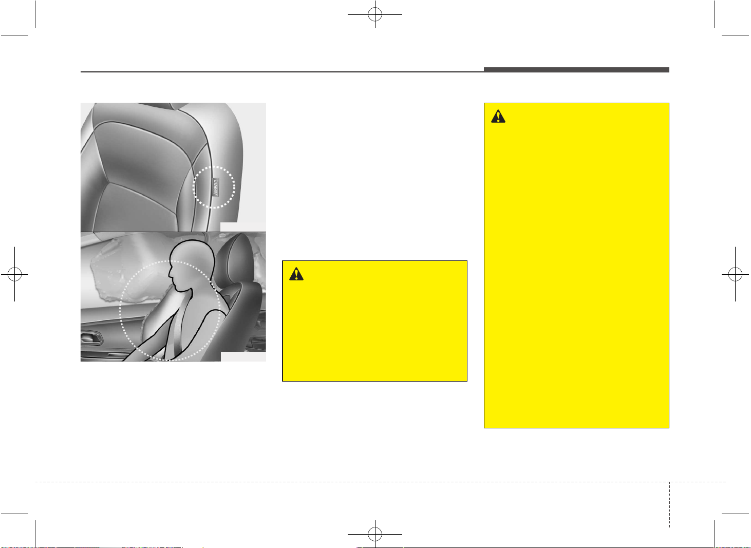
357
Safety features of your vehicle
Side impact air bag (if equipped)
Your vehicle is equipped with a side
impact air bag in each front seat. The
purpose of the air bag is to provide the
vehicle's driver and/or the front passen-
ger with additional protection than that
offered by the seat belt alone. The side
impact air bags are designed to deploy
only during certain side-impact collisions,
depending on the crash severity, angle,
speed and point of impact. The side air
bags are not designed to deploy in all
side impact situations.
WARNING
• The side impact air bag is sup-
plemental to the driver's and the
passenger's seat belt systems
and is not a substitute for them.
Therefore your seat belts must be
worn at all times while the vehicle
is in motion. The air bags deploy
only in certain side impact condi-
tions severe enough to cause
significant injury to the vehicle
occupants.
• For best protection from the side
impact air bag system and to
avoid being injured by the
deploying side impact air bag,
both front seat occupants should
sit in an upright position with the
seat belt properly fastened. The
driver's hands should be placed
on the steering wheel at the 9:00
and 3:00 positions. The passen-
ger's arms and hands should be
placed on their laps.
• Do not use any accessory seat
covers.
(Continued)
WARNING
Do not allow the passengers to lean
their heads or bodies onto doors,
put their arms on the doors, stretch
their arms out of the window, or
place objects between the doors
and passengers when they are
seated on seats equipped with side
and/or curtain air bags.
OJD032038
OJD032040
❈ The actual air bags in the vehicle may dif-
fer from the illustration.
JD PE eng 3.QXP 03.01.2017 16:42 Page 57
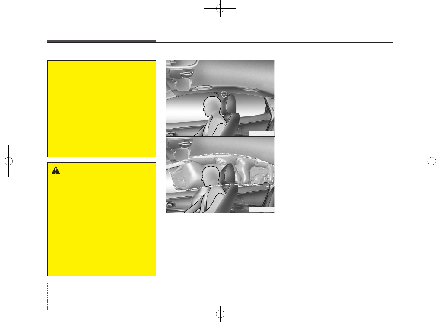
Safety features of your vehicle
583
Curtain air bag (if equipped)
Curtain air bags are located along both
sides of the roof rails above the front and
rear doors. They are designed to help
protect the heads of the front seat occu-
pants and the rear outboard seat occu-
pants in certain side impact collisions.
The curtain air bags are designed to
deploy during certain side impact colli-
sions, depending on the crash severity,
angle, speed and point of impact. The
curtain air bags are not designed to
deploy in all side impact situations, colli-
sions from the front or rear of the vehicle
or in most rollover situations.
OJD032039
OJD032041
(Continued)
• Use of seat covers could reduce
or prevent the effectiveness of
the system.
• To prevent unexpected deploy-
ment of the side impact air bag
that may result in personal injury,
avoid impact to the side impact
sensor when the ignition key is on.
• If the seat or seat cover is dam-
aged, we recommend that the
system be serviced by an author-
ized Kia dealer.
❈ The actual air bags in the vehicle may dif-
fer from the illustration.
WARNING - No attaching
objects
• Do not place any objects over the
air bag or between the air bag
and yourself. Also, do not attach
any objects around the area the
air bag inflates such as the door,
side door glass, front and rear pil-
lar.
• Do not place any objects between
the door and the seat. They may
become dangerous projectiles if
the side air bag inflates.
• Do not install any accessories on
the side or near the side air bags.
JD PE eng 3.QXP 03.01.2017 16:42 Page 58
359
Safety features of your vehicle
(Continued)
• Do not allow the passengers to
lean their heads or bodies onto
doors, put their arms on the
doors, stretch their arms out of
the window, or place objects
between the doors and passen-
gers when they are seated on
seats equipped with side and/or
curtain air bags.
• Never try to open or repair any
components of the side curtain
air bag system. We recommend
that the system be serviced by an
authorized Kia dealer.
Failure to follow the above men-
tioned instructions can result in
injury or death to the vehicle occu-
pants in an accident.
WARNING
• Do not hang heavy items on the
coat hooks for safety reasons.
• In order for side impact and cur-
tain air bags to provide the best
protection, both front seat occu-
pants and both outboard rear
occupants should sit in an
upright position with the seat
belts properly fastened.
Importantly, children should sit in
a proper child restraint system in
the rear seat.
• When children are seated in the
rear outboard seats, they must be
seated in the proper child
restraint system.
Make sure to put the child
restraint system as far away from
the door side as possible, and
secure the child restraint system
in a locked position.
(Continued)
WARNING - No attaching
objects
• Do not place any objects over the
air bag. Also, do not attach any
objects around the area the air
bag inflates such as the door, side
door glass, front and rear pillar,
roof side rail.
• Do not hang hard or breakable
objects on the clothes hanger.
JD PE eng 3.QXP 03.01.2017 16:42 Page 59
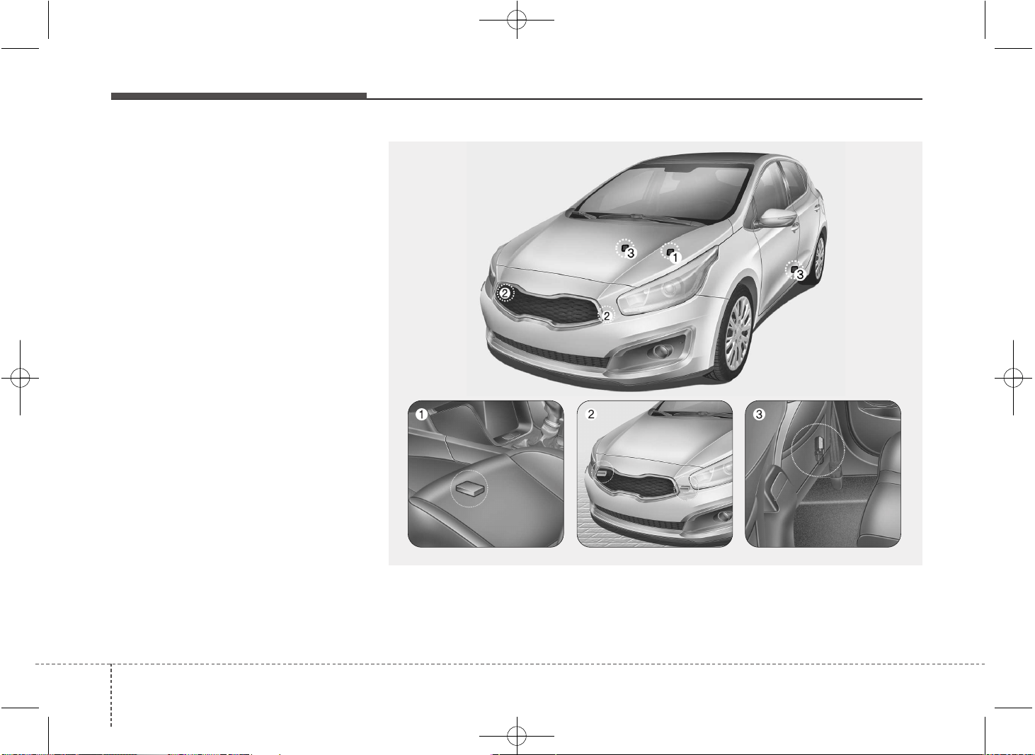
Safety features of your vehicle
603
Why didn’t my air bag go off in a
collision? (Inflation and non-infla-
tion conditions of the air bag)
There are many types of accidents in
which the air bag would not be expect-
ed to provide additional protection.
These include rear impacts, second or
third collisions in multiple impact
accidents, as well as low speed
impacts.
Air bag collision sensors
(1) SRS control module
(2) Front impact sensor
(3) Side impact sensor (if equipped)
OJD035042/OJD032043/OJD035044/OJD032045
JD PE eng 3.QXP 03.01.2017 16:42 Page 60
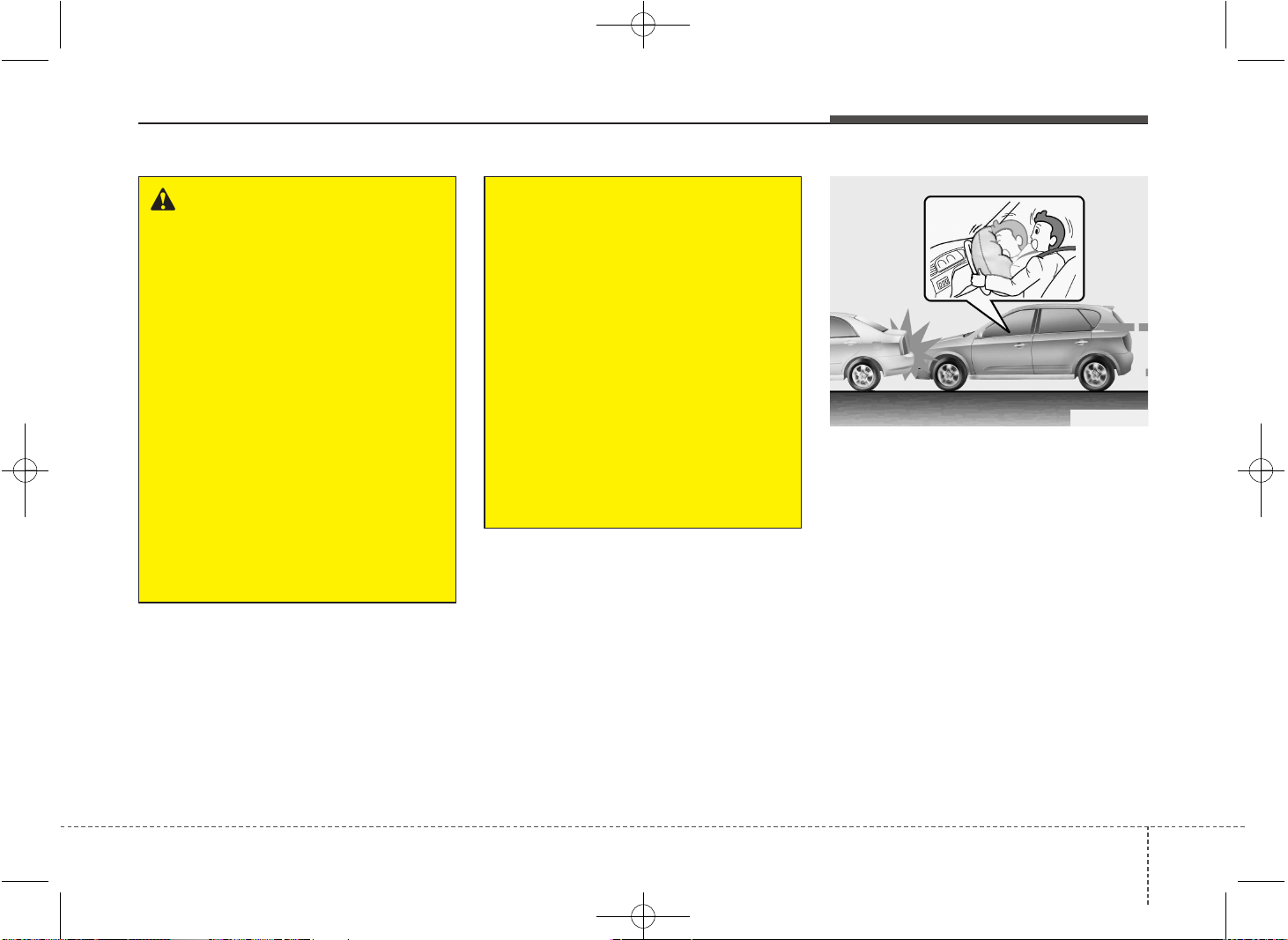
361
Safety features of your vehicle
Air bag inflation conditions
Front air bags
Front air bags are designed to inflate in a
frontal collision depending on the intensi-
ty, speed or angles of impact of the front
collision.
WARNING
• Do not hit or allow any objects to
impact the locations where air bag
or sensors are installed.
This may cause unexpected air
bag deployment, which could
result in serious personal injury
or death.
• If the installation location or
angle of the sensors is altered in
any way, the air bags may deploy
when they should not or they may
not deploy when they should,
causing severe injury or death.
Therefore, do not try to perform
maintenance on or around the air
bag sensors. We recommend that
the system be serviced by an
authorized Kia dealer.
(Continued)
(Continued)
• Problems may arise if the sensor
installation angles are changed
due to the deformation of the
front bumper, body or B pillar and
C pillars where side collision sen-
sors are installed. We recommend
that the system be serviced by an
authorized Kia dealer.
• Your vehicle has been designed
to absorb impact and deploy the
air bag(s) in certain collisions.
Installing bumper guards or
replacing a bumper with non-gen-
uine parts may adversely affect
your vehicles collision and air
bag deployment performance.
OED036096
JD PE eng 3.QXP 03.01.2017 16:42 Page 61
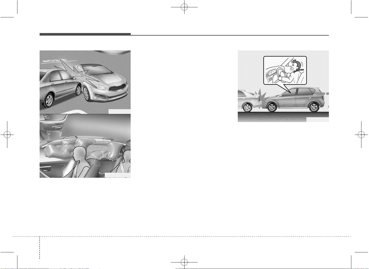
Safety features of your vehicle
623
Side impact and curtain air bags
(if equipped)
Side impact and/or curtain air bags are
designed to inflate when an impact is
detected by side collision sensors
depending on the strength, speed or
angles of impact resulting from a side
impact collision.
Although the front air bags (driver’s and
front passenger’s air bags) are designed
to inflate only in frontal collisions, they
also may inflate in other types of colli-
sions if the front impact sensors detect a
sufficient impact. Side air bags (side
impact and/or curtain air bags) are
designed to inflate only in side impact
collisions, but they may inflate in other
collisions if the side impact sensors
detect a sufficient impact.
If the vehicle chassis is impacted by
bumps or objects on unimproved roads
or sidewalks, air bags may deploy. Drive
carefully on unimproved roads or on sur-
faces not designed for vehicle traffic to
prevent unintended air bag deployment.
Air bag non-inflation conditions
• In certain low-speed collisions the air
bags may not deploy. The air bags are
designed not to deploy in such cases
because they may not provide benefits
beyond the protection of the seat belts
in such collisions.
OED036099
OJD035048
OGDE031045
❈ The actual air bags in the vehicle may dif-
fer from the illustration.
JD PE eng 3.QXP 03.01.2017 16:42 Page 62
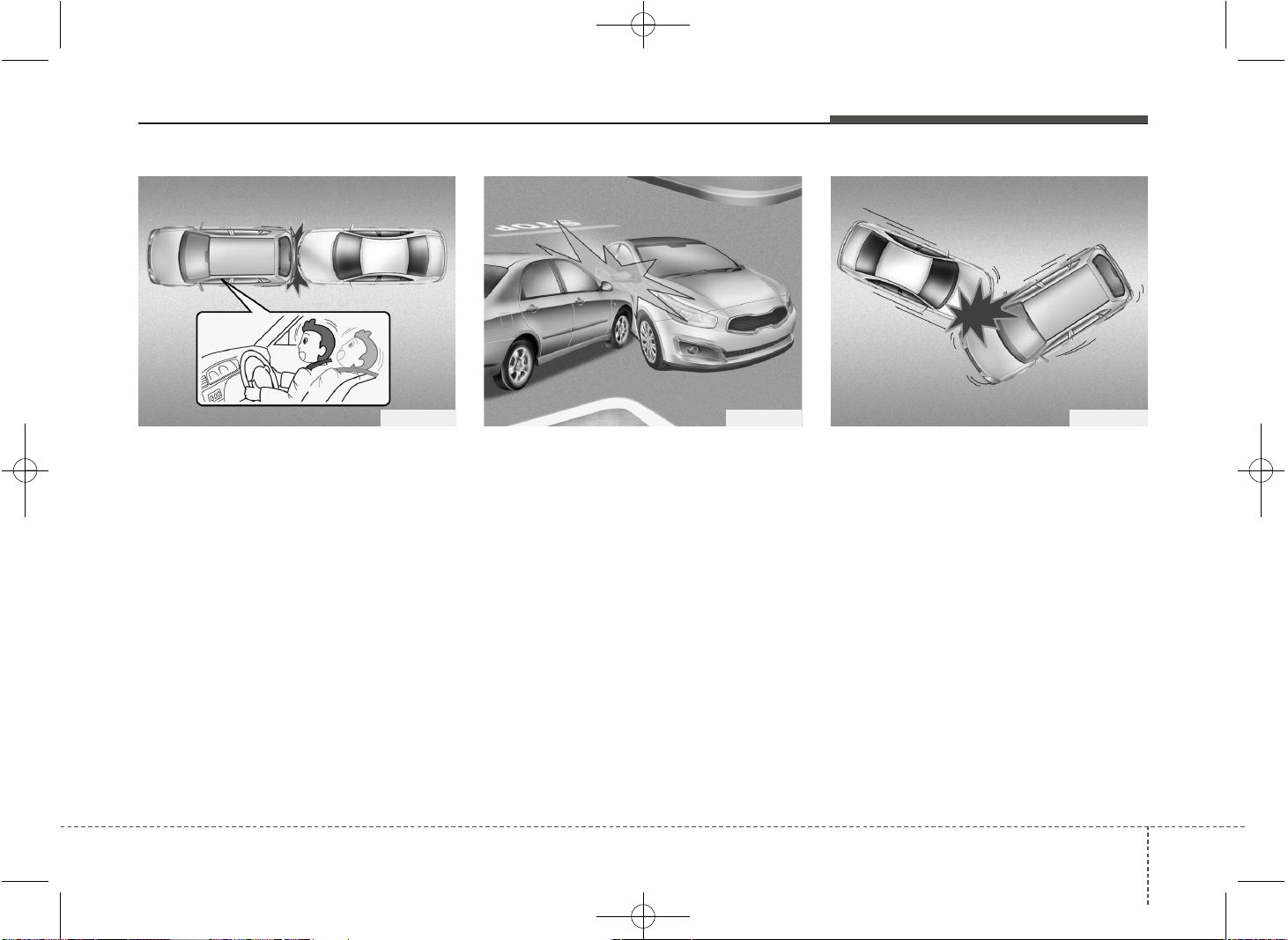
363
Safety features of your vehicle
• Air bags are not designed to inflate in
rear collisions, because occupants are
moved backward by the force of the
impact. In this case, inflated air bags
would not be able to provide any addi-
tional benefit.
• Front air bags may not inflate in side
impact collisions, because occupants
move to the direction of the collision,
and thus in side impacts, frontal air bag
deployment would not provide addi-
tional occupant protection.
• However, if equipped with side impact
and curtain air bags, the air bags may
inflate depending on the intensity, vehi-
cle speed and angles of impact.
• In an angled collision, the force of
impact may direct the occupants in a
direction where the air bags would not
be able to provide any additional bene-
fit, and thus the sensors may not
deploy any air bags.
OED036102OJD035048OED036100
JD PE eng 3.QXP 03.01.2017 16:42 Page 63
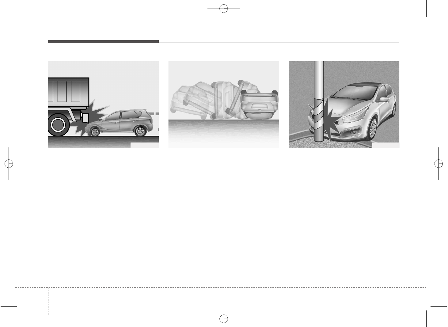
Safety features of your vehicle
643
• Just before impact, drivers often brake
heavily. Such heavy braking lowers the
front portion of the vehicle causing it to
“ride” under a vehicle with a higher
ground clearance. Air bags may not
inflate in this "under-ride" situation
because deceleration forces that are
detected by sensors may be signifi-
cantly replaced by such “under-ride”
collisions.
• Air bags may not inflate in rollover acci-
dents because the vehicle can not
detect rollover accident.
However, side and/or curtain air bags
may inflate when the vehicle is rolled
over following (or after) side impact col-
lision.
• Air bags may not inflate if the vehicle
collides with objects such as utility
poles or trees, where the point of
impact is concentrated to one area and
the full force of the impact is not deliv-
ered to the sensors.
OED036103 OED036104 OJD035050
JD PE eng 3.QXP 03.01.2017 16:42 Page 64
365
Safety features of your vehicle
SRS Care
The SRS is virtually maintenance-free
and so there are no parts you can safely
service by yourself. If the SRS air bag
warning light does not illuminate, or con-
tinuously remains on, we recommend
that the system be inspected by an
authorized Kia dealer.
WARNING
• Modification to SRS components
or wiring, including the addition
of any kind of badges to the pad
covers or modifications to the
body structure, can adversely
affect SRS performance and lead
to possible injury.
• For cleaning the air bag pad cov-
ers, use only a soft, dry cloth or
one which has been moistened
with plain water. Solvents or
cleaners could adversely affect
the air bag covers and proper
deployment of the system.
• No objects should be placed over
or near the air bag modules on
the steering wheel, instrument
panel, and the front passenger's
panel above the glove box,
because any such object could
cause harm if the vehicle is in a
crash severe enough to cause
the air bags to inflate.
(Continued)
(Continued)
• If the air bags inflate, we recom-
mend that the system be replaced
by an authorized Kia dealer.
• Do not tamper with or disconnect
SRS wiring, or other components
of the SRS system. Doing so
could result in injury, due to acci-
dental inflation of the air bags or
by rendering the SRS inopera-
tive.
• If components of the air bag sys-
tem must be discarded, or if the
vehicle must be scrapped, certain
safety precautions must be
observed. An authorized Kia
dealer knows these precautions
and can give you the necessary
information. Failure to follow
these precautions and proce-
dures could increase the risk of
personal injury.
• If your car was flooded and has
soaked carpeting or water on floor-
ing, you shouldn't try to start the
engine; we recommend that you
contact an authorized Kia dealer.
JD PE eng 3.QXP 03.01.2017 16:42 Page 65
Safety features of your vehicle
663
Additional safety precautions
• Never let passengers ride in the
cargo area or on top of a folded-
down back seat. All occupants should
sit upright, fully back in their seats with
their seat belts on and their feet on the
floor.
• Passengers should not move out of
or change seats while the vehicle is
moving. A passenger who is not wear-
ing a seat belt during a crash or emer-
gency stop can be thrown against the
inside of the vehicle, against other
occupants, or out of the vehicle.
• Each seat belt is designed to
restrain one occupant. If more than
one person uses the same seat belt,
they could be seriously injured or killed
in a collision.
• Do not use any accessories on seat
belts. Devices claiming to improve
occupant comfort or reposition the seat
belt can reduce the protection provided
by the seat belt and increase the
chance of serious injury in a crash.
• Passengers should not place hard
or sharp objects between them-
selves and the air bags. Carrying
hard or sharp objects on your lap or in
your mouth can result in injuries if an
air bag inflates.
• Keep occupants away from the air
bag covers. All occupants should sit
upright, fully back in their seats with
their seat belts on and their feet on the
floor. If occupants are too close to the
air bag covers, they could be injured if
the air bags inflate.
• Do not attach or place objects on or
near the air bag covers. Any object
attached to or placed on the front or
side impact air bag covers could inter-
fere with the proper operation of the air
bags.
• Do not modify the front seats.
Modification of the front seats could
interfere with the operation of the sup-
plemental restraint system sensing
components or side air bags.
• Do not place items under the front
seats. Placing items under the front
seats could interfere with the operation
of the supplemental restraint system
sensing components and wiring har-
nesses.
• Never hold an infant or child on your
lap. The infant or child could be seri-
ously injured or killed in the event of a
crash. All infants and children should
be properly restrained in appropriate
child safety seats or seat belts in the
rear seat.
WARNING
• Sitting improperly or out of posi-
tion can cause occupants to be
shifted too close to a deploying
air bag, strike the interior struc-
ture or be thrown from the vehicle
resulting in serious injury or
death.
• Always sit upright with the seat-
back in an upright position, cen-
tered on the seat cushion with
your seat belt on, legs comfort-
ably extended and your feet on
the floor.
JD PE eng 3.QXP 03.01.2017 16:42 Page 66
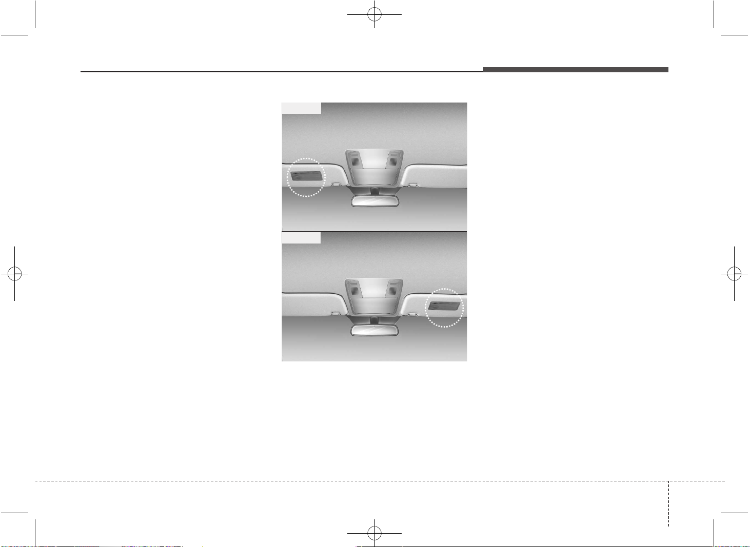
367
Safety features of your vehicle
Adding equipment to or modify-
ing your air bag-equipped vehicle
If you modify your vehicle by changing
your vehicle's frame, bumper system,
front end or side sheet metal or ride
height, this may affect the operation of
your vehicle's air bag system.
Air bag warning label
(if equipped)
Air bag warning labels are attached to
alert driver and passengers of potential
risk of air bag system.
Note that these government warnings
focus on the risk of children. We also
want you to be aware of the risks adults
are exposed to which have been
described in previous pages.
■ Type B
OJD032051
■ Type A
OJD032052
JD PE eng 3.QXP 03.01.2017 16:42 Page 67

Features of your vehicle
Keys . . . . . . . . . . . . . . . . . . . . . . . . . . . . . . . . . . . . . . 4-4
• Record your key number . . . . . . . . . . . . . . . . . . . . . . . 4-4
• Key operations . . . . . . . . . . . . . . . . . . . . . . . . . . . . . . . . 4-4
• Immobilizer system . . . . . . . . . . . . . . . . . . . . . . . . . . . . 4-4
Remote keyless entry . . . . . . . . . . . . . . . . . . . . . . . . 4-6
• Remote keyless entry system operations. . . . . . . . . . . 4-6
• Transmitter precautions . . . . . . . . . . . . . . . . . . . . . . . . 4-8
• Battery replacement . . . . . . . . . . . . . . . . . . . . . . . . . . . 4-9
Smart key . . . . . . . . . . . . . . . . . . . . . . . . . . . . . . . . 4-11
• Smart key function . . . . . . . . . . . . . . . . . . . . . . . . . . . 4-11
• Smart key precautions . . . . . . . . . . . . . . . . . . . . . . . . 4-13
• Door lock/unlock in an emergency situation . . . . . . 4-13
Theft-alarm system . . . . . . . . . . . . . . . . . . . . . . . . 4-14
• Armed stage . . . . . . . . . . . . . . . . . . . . . . . . . . . . . . . . . 4-14
• Theft-alarm stage . . . . . . . . . . . . . . . . . . . . . . . . . . . . 4-15
• Disarmed stage. . . . . . . . . . . . . . . . . . . . . . . . . . . . . . . 4-16
Door locks . . . . . . . . . . . . . . . . . . . . . . . . . . . . . . . . 4-17
• From outside . . . . . . . . . . . . . . . . . . . . . . . . . . . . . . . . 4-17
• From inside . . . . . . . . . . . . . . . . . . . . . . . . . . . . . . . . . 4-18
• Deadlocks . . . . . . . . . . . . . . . . . . . . . . . . . . . . . . . . . . . 4-20
• Door lock/unlock features. . . . . . . . . . . . . . . . . . . . . . 4-20
• Child-protector rear door lock. . . . . . . . . . . . . . . . . . 4-21
Tailgate . . . . . . . . . . . . . . . . . . . . . . . . . . . . . . . . . . 4-22
• Opening the tailgate . . . . . . . . . . . . . . . . . . . . . . . . . . 4-22
• Closing the tailgate . . . . . . . . . . . . . . . . . . . . . . . . . . . 4-22
• Emergency tailgate safety release . . . . . . . . . . . . . . . 4-23
Windows . . . . . . . . . . . . . . . . . . . . . . . . . . . . . . . . . 4-24
• Power windows . . . . . . . . . . . . . . . . . . . . . . . . . . . . . . 4-25
• Manual windows . . . . . . . . . . . . . . . . . . . . . . . . . . . . . 4-28
Hood. . . . . . . . . . . . . . . . . . . . . . . . . . . . . . . . . . . . . 4-29
• Opening the hood . . . . . . . . . . . . . . . . . . . . . . . . . . . . 4-29
• Closing the hood . . . . . . . . . . . . . . . . . . . . . . . . . . . . . 4-30
Fuel filler lid . . . . . . . . . . . . . . . . . . . . . . . . . . . . . . 4-31
• Opening the fuel filler lid . . . . . . . . . . . . . . . . . . . . . . 4-31
• Closing the fuel filler lid . . . . . . . . . . . . . . . . . . . . . . . 4-31
Panorama sunroof . . . . . . . . . . . . . . . . . . . . . . . . . 4-34
• Sunroof open warning. . . . . . . . . . . . . . . . . . . . . . . . . 4-35
• Sunshade . . . . . . . . . . . . . . . . . . . . . . . . . . . . . . . . . . . 4-35
• Sliding the sunroof . . . . . . . . . . . . . . . . . . . . . . . . . . . 4-35
• Tilting the sunroof. . . . . . . . . . . . . . . . . . . . . . . . . . . . 4-36
• Closing the sunroof . . . . . . . . . . . . . . . . . . . . . . . . . . . 4-36
• Resetting the sunroof . . . . . . . . . . . . . . . . . . . . . . . . . 4-37
Steering wheel . . . . . . . . . . . . . . . . . . . . . . . . . . . . . 4-39
• Electronic power steering . . . . . . . . . . . . . . . . . . . . . . 4-39
• Tilt and telescopic steering . . . . . . . . . . . . . . . . . . . . . 4-40
• Heated steering wheel . . . . . . . . . . . . . . . . . . . . . . . . . 4-40
• Horn . . . . . . . . . . . . . . . . . . . . . . . . . . . . . . . . . . . . . . . 4-41
• Flex steering wheel . . . . . . . . . . . . . . . . . . . . . . . . . . . 4-42
Mirrors . . . . . . . . . . . . . . . . . . . . . . . . . . . . . . . . . . 4-44
• Inside rearview mirror . . . . . . . . . . . . . . . . . . . . . . . . 4-44
• Outside rearview mirror. . . . . . . . . . . . . . . . . . . . . . . 4-45
Instrument cluster (Normal vision) . . . . . . . . . . . 4-48
• Instrument panel illumination . . . . . . . . . . . . . . . . . . 4-49
• Gauges . . . . . . . . . . . . . . . . . . . . . . . . . . . . . . . . . . . . . 4-49
• Manual transaxle shift indicator . . . . . . . . . . . . . . . . 4-51
• Automatic transaxle shift position indicator . . . . . . 4-51
4

• Dual clutch transmission shift indicator. . . . . . . . . . 4-52
• Speed limiter indicator . . . . . . . . . . . . . . . . . . . . . . . . 4-53
• Odometer . . . . . . . . . . . . . . . . . . . . . . . . . . . . . . . . . . . 4-53
• Trip computer . . . . . . . . . . . . . . . . . . . . . . . . . . . . . . . 4-53
Instrument cluster (Super vision) . . . . . . . . . . . . . 4-61
• Instrument panel illumination . . . . . . . . . . . . . . . . . . 4-63
• Gauges . . . . . . . . . . . . . . . . . . . . . . . . . . . . . . . . . . . . . 4-63
• Manual transaxle shift indicator . . . . . . . . . . . . . . . . 4-66
• Automatic transaxle shift position indicator . . . . . . 4-67
• Dual clutch transmission shift indicator. . . . . . . . . . 4-67
• Speed limiter indicator . . . . . . . . . . . . . . . . . . . . . . . 4-68
• Odometer . . . . . . . . . . . . . . . . . . . . . . . . . . . . . . . . . . . 4-68
• Trip computer . . . . . . . . . . . . . . . . . . . . . . . . . . . . . . . 4-69
• LCD display information . . . . . . . . . . . . . . . . . . . . . . 4-76
• Warnings and indicators. . . . . . . . . . . . . . . . . . . . . . . 4-82
LCD display warnings and indicators
(instrument panel display) . . . . . . . . . . . . . . . . . 4-93
Rear parking assist system . . . . . . . . . . . . . . . . . . 4-95
• Operation . . . . . . . . . . . . . . . . . . . . . . . . . . . . . . . . . . . 4-95
• Non-operational conditions . . . . . . . . . . . . . . . . . . . . 4-97
• Precautions. . . . . . . . . . . . . . . . . . . . . . . . . . . . . . . . . . 4-97
• Self-diagnosis . . . . . . . . . . . . . . . . . . . . . . . . . . . . . . . . 4-98
Parking assist system . . . . . . . . . . . . . . . . . . . . . . . 4-99
• Operation . . . . . . . . . . . . . . . . . . . . . . . . . . . . . . . . . . 4-100
• Non-operational conditions . . . . . . . . . . . . . . . . . . . 4-102
• Self-diagnosis . . . . . . . . . . . . . . . . . . . . . . . . . . . . . . . 4-103
Smart Parking Assist System (SPAS) . . . . . . . . . 4-104
• Operating condition . . . . . . . . . . . . . . . . . . . . . . . . . 4-105
• Non-operating condition . . . . . . . . . . . . . . . . . . . . . . 4-106
• How the system works (Parking mode) . . . . . . . . . 4-109
• How the system works (Exit mode) . . . . . . . . . . . . . 4-115
• Additional instructions (messages). . . . . . . . . . . . . . 4-118
• System malfunction . . . . . . . . . . . . . . . . . . . . . . . . . . 4-119
Rearview camera . . . . . . . . . . . . . . . . . . . . . . . . . 4-120
Hazard warning flasher. . . . . . . . . . . . . . . . . . . . 4-120
Lighting . . . . . . . . . . . . . . . . . . . . . . . . . . . . . . . . . 4-121
• Battery saver function. . . . . . . . . . . . . . . . . . . . . . . . 4-121
• Headlamp delay function . . . . . . . . . . . . . . . . . . . . . 4-121
• Headlight (Headlamp) welcome function . . . . . . . . 4-121
• Static bending light . . . . . . . . . . . . . . . . . . . . . . . . . . 4-122
• Lighting control . . . . . . . . . . . . . . . . . . . . . . . . . . . . . 4-122
• High - beam operation . . . . . . . . . . . . . . . . . . . . . . . 4-124
• High beam assist (HBA) . . . . . . . . . . . . . . . . . . . . . . 4-125
• Turn signals and lane change signals . . . . . . . . . . . 4-126
• Front fog light . . . . . . . . . . . . . . . . . . . . . . . . . . . . . . 4-127
• Rear fog light . . . . . . . . . . . . . . . . . . . . . . . . . . . . . . . 4-128
• Daytime running light. . . . . . . . . . . . . . . . . . . . . . . . 4-128
• Headlight leveling device . . . . . . . . . . . . . . . . . . . . . 4-128
• Adaptive Front Lighting System (AFLS) . . . . . . . . 4-129
Wipers and washers . . . . . . . . . . . . . . . . . . . . . . . 4-131
• Windshield wipers (front). . . . . . . . . . . . . . . . . . . . . 4-131
• Windshield washers (front) . . . . . . . . . . . . . . . . . . . 4-133
• Rear window wiper and washer switch. . . . . . . . . . 4-134
Interior light . . . . . . . . . . . . . . . . . . . . . . . . . . . . . 4-135
• Interior lamp AUTO cut . . . . . . . . . . . . . . . . . . . . . . 4-135
• Map lamp . . . . . . . . . . . . . . . . . . . . . . . . . . . . . . . . . . 4-135
• Room lamp . . . . . . . . . . . . . . . . . . . . . . . . . . . . . . . . . 4-136
• Vanity mirror lamp . . . . . . . . . . . . . . . . . . . . . . . . . . 4-136
4

• Luggage room lamp . . . . . . . . . . . . . . . . . . . . . . . . . 4-137
• Glove box lamp . . . . . . . . . . . . . . . . . . . . . . . . . . . . . 4-137
Welcome system . . . . . . . . . . . . . . . . . . . . . . . . . . 4-138
• Headlamp welcome . . . . . . . . . . . . . . . . . . . . . . . . . . 4-138
• Interior light. . . . . . . . . . . . . . . . . . . . . . . . . . . . . . . . 4-138
• Puddle lamp . . . . . . . . . . . . . . . . . . . . . . . . . . . . . . . . 4-138
Defroster . . . . . . . . . . . . . . . . . . . . . . . . . . . . . . . . 4-139
• Rear window defroster . . . . . . . . . . . . . . . . . . . . . . . 4-139
Manual climate control system . . . . . . . . . . . . . . 4-140
• Heating and air conditioning . . . . . . . . . . . . . . . . . . 4-141
• System operation . . . . . . . . . . . . . . . . . . . . . . . . . . . . 4-145
• Climate control air filter. . . . . . . . . . . . . . . . . . . . . . 4-147
• Checking the amount of air conditioner
refrigerant and compressor lubricant. . . . . . . . . . 4-148
Automatic climate control system . . . . . . . . . . . 4-149
• Automatic heating and air conditioning . . . . . . . . . 4-150
• Manual heating and air conditioning . . . . . . . . . . . 4-152
• System operation . . . . . . . . . . . . . . . . . . . . . . . . . . . . 4-157
• Climate control air filter. . . . . . . . . . . . . . . . . . . . . . 4-157
• Checking the amount of air conditioner
refrigerant and compressor lubricant. . . . . . . . . . 4-160
Windshield defrosting and defogging. . . . . . . . . 4-161
• Manual climate control system . . . . . . . . . . . . . . . . 4-161
• Automatic climate control system . . . . . . . . . . . . . . 4-162
Clean air . . . . . . . . . . . . . . . . . . . . . . . . . . . . . . . . 4-163
Storage compartment. . . . . . . . . . . . . . . . . . . . . . 4-164
• Center console storage . . . . . . . . . . . . . . . . . . . . . . . 4-164
• Sliding armrest . . . . . . . . . . . . . . . . . . . . . . . . . . . . . 4-164
• Glove box . . . . . . . . . . . . . . . . . . . . . . . . . . . . . . . . . . 4-165
• Cool box . . . . . . . . . . . . . . . . . . . . . . . . . . . . . . . . . . . 4-165
• Sunglass holder . . . . . . . . . . . . . . . . . . . . . . . . . . . . . 4-166
• Luggage tray . . . . . . . . . . . . . . . . . . . . . . . . . . . . . . . 4-166
• Luggage side tray . . . . . . . . . . . . . . . . . . . . . . . . . . . 4-167
Interior features . . . . . . . . . . . . . . . . . . . . . . . . . . 4-168
• Cigarette lighter. . . . . . . . . . . . . . . . . . . . . . . . . . . . . 4-168
• Ashtray . . . . . . . . . . . . . . . . . . . . . . . . . . . . . . . . . . . . 4-168
• Cup holder . . . . . . . . . . . . . . . . . . . . . . . . . . . . . . . . . 4-169
• Bottle holder. . . . . . . . . . . . . . . . . . . . . . . . . . . . . . . . 4-170
• Sunvisor . . . . . . . . . . . . . . . . . . . . . . . . . . . . . . . . . . . 4-171
• Power outlet . . . . . . . . . . . . . . . . . . . . . . . . . . . . . . . . 4-172
• Aux, USB and iPod . . . . . . . . . . . . . . . . . . . . . . . . . . 4-173
• Clothes hanger . . . . . . . . . . . . . . . . . . . . . . . . . . . . . . 4-173
• Floor mat anchor(s). . . . . . . . . . . . . . . . . . . . . . . . . . 4-174
• Luggage net (holder). . . . . . . . . . . . . . . . . . . . . . . . . 4-175
• Cargo area cover . . . . . . . . . . . . . . . . . . . . . . . . . . . . 4-175
• Barrier net . . . . . . . . . . . . . . . . . . . . . . . . . . . . . . . . . 4-176
• Cargo security screen . . . . . . . . . . . . . . . . . . . . . . . . 4-178
• Luggage rail system. . . . . . . . . . . . . . . . . . . . . . . . . . 4-180
• Shopping bag holder . . . . . . . . . . . . . . . . . . . . . . . . . 4-181
Exterior features. . . . . . . . . . . . . . . . . . . . . . . . . . 4-182
• Mounting bracket for roof carrier . . . . . . . . . . . . . 4-182
• Roof rack . . . . . . . . . . . . . . . . . . . . . . . . . . . . . . . . . . 4-183
Audio System . . . . . . . . . . . . . . . . . . . . . . . . . . . . 4-185
• Antenna . . . . . . . . . . . . . . . . . . . . . . . . . . . . . . . . . . . 4-185
• Steering wheel audio controls. . . . . . . . . . . . . . . . . . 4-186
• AUX, USB and iPod
®
port . . . . . . . . . . . . . . . . . . . . 4-187
4
Features of your vehicle
44
Record your key number
The key code number is
stamped on the key
code tag attached to the
key set. Should you lose
your keys, we recom-
mend that you contact an authorized Kia
dealer. Remove the key code tag and
store it in a safe place. Also, record the
code number and keep it in a safe and
handy place, but not in the vehicle.
Key operations
• Used to start the engine.
• Used to lock and unlock the doors.
Immobilizer system
Your vehicle may be equipped with an
electronic engine immobilizer system to
reduce the risk of unauthorized vehicle
use.
Your immobilizer system is comprised of
a small transponder in the key and elec-
tronic devices inside the vehicle.
Vehicles without smart key system
With the immobilizer system, whenever
you insert your ignition key into the igni-
tion switch and turn it to ON, it checks
and determines and verifies if the ignition
key is valid or not.
If the key is valid, the engine will start.
If the key is invalid, the engine will not
start.
To deactivate the immobilizer system:
Insert the ignition key into the key cylin-
der and turn it to the ON position.
To activate the immobilizer system:
Turn the ignition key to the OFF position.
The immobilizer system activates auto-
matically. Without a valid ignition key for
your vehicle, the engine will not start.
KEYS
WARNING - Ignition key
(Smart key)
Leaving children unattended in a
vehicle with the ignition key (Smart
key) is dangerous even if the key is
not in the ignition or start button is
ACC or ON position. Children copy
adults and they could place the key
in the ignition or press the start but-
ton. The ignition key (Smart key)
would enable children to operate
power windows or other controls, or
even make the vehicle move, which
could result in serious bodily injury
or even death. Never leave the keys
in your vehicle with unsupervised
children, when the engine is running.
WARNING
We recommend that you use parts
for replacement from an authorized
Kia dealer. If an aftermarket key is
used, the ignition switch may not
return to ON after START. If this
happens, the starter will continue
to operate causing damage to the
starter motor and possible fire due
to excessive current in the wiring.
45
Features of your vehicle
Vehicles with smart key system
Whenever the engine start/stop button is
changed to the ON position, the immobi-
lizer system checks and verifies if the key
is valid or not.
If the key is valid, the engine will start.
If the key is invalid, the engine will not
start.
To deactivate the immobilizer system
Change the engine start/stop button to
the ON position.
To activate the immobilizer system
Change the engine start/stop button to
the OFF position. The immobilizer sys-
tem activates automatically. Without a
valid smart key for your vehicle, the
engine will not start.
✽✽
NOTICE
When starting the engine, do not use the
key with other immobilizer keys around.
Otherwise the engine may not start or
may stop soon after it starts. Keep each
key separate in order to avoid a starting
malfuntioin.
✽
✽
NOTICE
If you need additional keys or lose your
keys, we recommend that you consult an
authorized Kia dealer.
CAUTION
The transponder in your ignition
key is an important part of the
immobilizer system. It is designed
to give years of trouble-free service,
however you should avoid expo-
sure to moisture, static electricity
and rough handling. Immobilizer
system malfunction could occur.
CAUTION
Do not change, alter or adjust the
immobilizer system because it
could cause the immobilizer sys-
tem to malfunction. We recommend
that the system be serviced by an
authorized Kia dealer.
Malfunctions caused by improper
alterations, adjustments or modifi-
cations to the immobilizer system
are not covered by your vehicle
manufacturer warranty.
WARNING
In order to prevent theft of your vehi-
cle, do not leave spare keys any-
where in your vehicle. Your immobi-
lizer password is a customer unique
password and should be kept confi-
dential. Do not leave this number
anywhere in your vehicle.
CAUTION
Do not put metal accessories near
the ignition switch.
The engine may not start because
the metal accessories may interrupt
the transponder signal from nor-
mally transmitting.
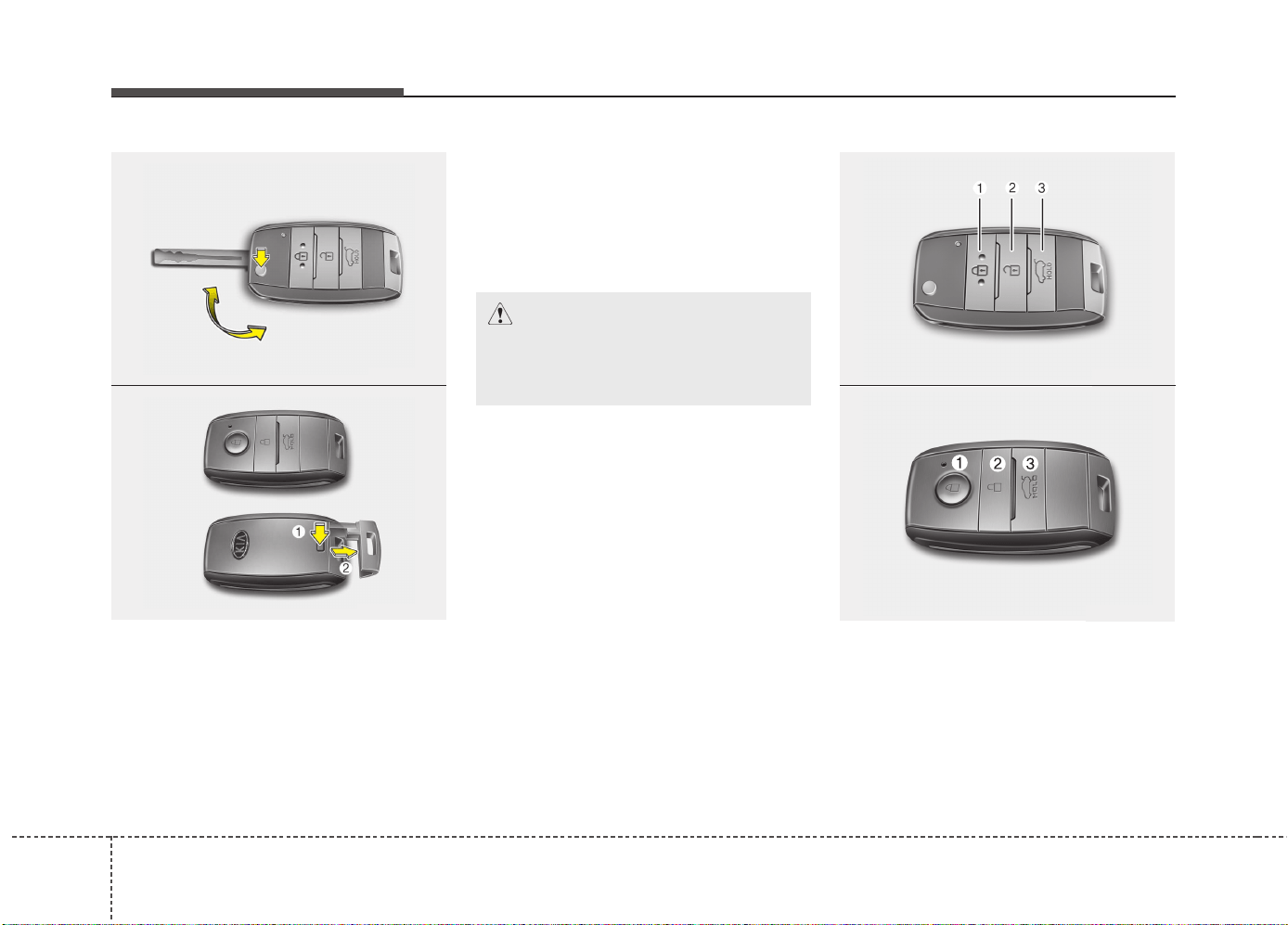
Features of your vehicle
64
Remote keyless entry system
operations
Type A
• To unfold the key, press the release
button then the key will unfold automat-
ically.
• To fold the key, fold the key manually
while pressing the release button.
Type B
• To remove the mechanical key, press
and hold the release button and
remove the mechanical key.
• To reinstall the mechanical key, put the
key into the hole and push it until a
click sound is heard.
REMOTE KEYLESS ENTRY (IF EQUIPPED)
CAUTION
Do not fold the key without press-
ing the release button. This may
damage the key.
OJD043244
OJD042002
■ Type A
■ Type B
OJD043245
OJD042001
■ Type A
■ Type B

47
Features of your vehicle
Lock (1)
1. Close all doors.
2. Press the lock button.
3. The hazard warning light will blink
once to indicate that all doors are
locked (the engine hood and tailgate
must be closed). Also, the outside
rearview mirror will automatically fold if
the outside rearview mirror folding
switch (Type B) is in the AUTO position
(if equipped).
✽✽
NOTICE
The doors will not lock if any door is
opened.
Unlock (2)
1. Press the unlock button.
2. The hazard warning lights will blink
twice to indicate that all doors are
unlocked. Also, the outside rearview
mirror will automatically unfold if the
outside rearview mirror folding switch
(Type B) is in the AUTO position (if
equipped).
✽✽
NOTICE
After unlocking all doors, the doors will
lock and the outside rearview mirror
will unfold if the outside rearview mir-
ror folding switch (Type B) is in the
AUTO position (if equipped) unless a
door is opened within 30 seconds.
Tailgate unlock (3)
1. Press the tailgate unlock button for
more than 1 second.
2. The hazard warning light will blink
twice to indicate the tailgate is
unlocked.
✽✽
NOTICE
• After unlocking the tailgate, the tail-
gate will lock automatically unless it is
opened within 30 seconds.
• Once the tailgate is opened and then
closed, the tailgate will lock automati-
cally.
• The word "HOLD" is written on the
button to inform you that you must
press and hold the button.
Features of your vehicle
84
Transmitter precautions
✽✽
NOTICE
The transmitter will not work if any of
following occur:
• The ignition key is in ignition switch.
• You exceed the operating distance
limit (about 10 m [30 feet]).
• The battery in the transmitter is
weak.
• Other vehicles or objects may be
blocking the signal.
• The weather is extremely cold.
• The transmitter is close to a radio
transmitter such as a radio station or
an airport which can interfere with
normal operation of the transmitter.
When the transmitter does not work cor-
rectly, open and close the door with the
ignition key. If you have a problem with
the transmitter, we recommend that you
contact an authorized Kia dealer.
(Continued)
(Continued)
• If the transmitter is in close proximity
to your cell phone or smart phone, the
signal from the transmitter could be
blocked by normal operation of your
cell phone or smart phone. This is
especially important when the phone
is active such as making call, receiving
calls, text messaging, and/or sending/
receiving emails. Avoid placing the
transmitter and your cell phone or
smart phone in the same pants or
jacket pocket and maintain adequate
distance between the two devices.
CAUTION
Changes or modifications not
expressly approved by the party
responsible for compliance could
void the user’s authority to operate
the equipment. If the keyless entry
system is inoperative due to
changes or modifications not
expressly approved by the party
responsible for compliance, it will
not be covered by your manufactur-
er’s vehicle warranty.
CAUTION
• Keep the transmitter away from
water or any liquid. If the keyless
entry system is inoperative due to
exposure to water or liquids, it
will not be covered by your manu-
facturer vehicle warranty.
• Keep the transmitter away from
electromagnetic materials that
blocks electromagnetic waves to
the key surface.
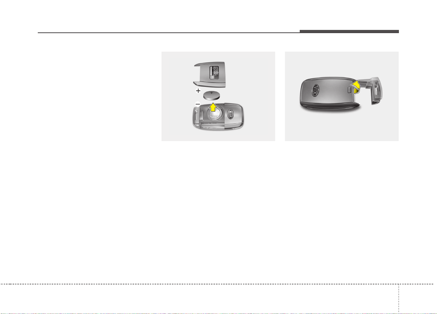
49
Features of your vehicle
Battery replacement
A battery should last for several years,
but if the transmitter or smart key is not
working properly, try replacing the bat-
tery with a new one. If you are unsure
how to use or replace the battery, we rec-
ommend that you contact an authorized
Kia dealer.
Type A
1. Insert a slim tool into the slot and gen-
tly pry open the cover.
2. Replace the battery with a new battery
(CR2032). When replacing the battery,
make sure the battery position.
3. Install the rear cover.
Type B
1. Insert a slim tool into the slot and gen-
tly pry open the cover.
OYDDCO2005 OJD042003
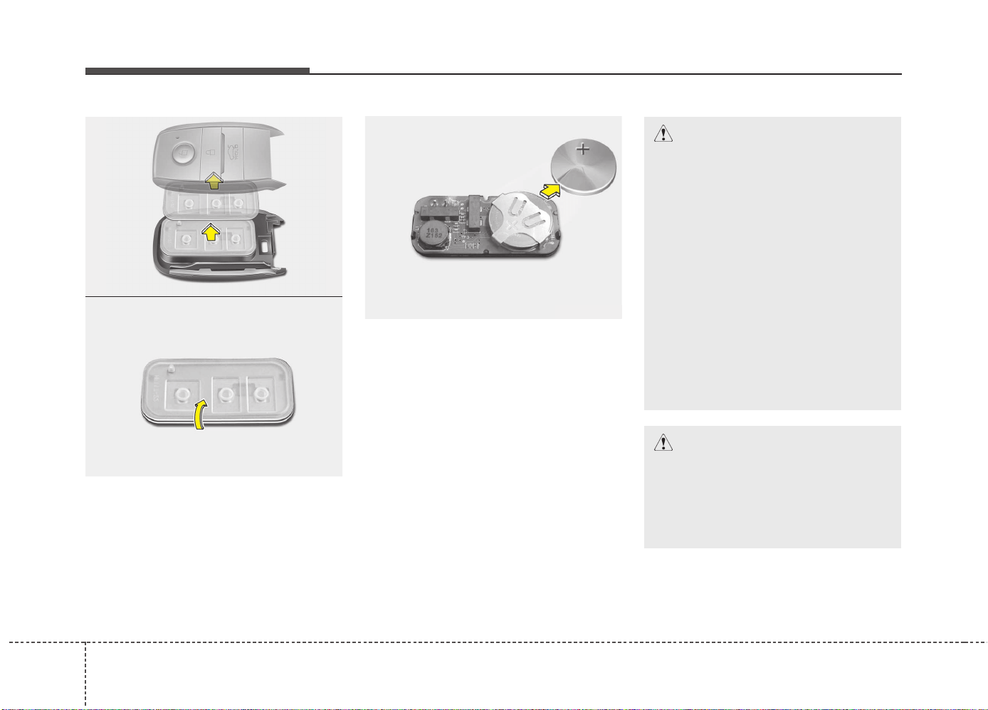
Features of your vehicle
104
2. Pull the smart key module out.
3. Turn the smart key module over.
4. Push the battery out from the battery
holder.
5. Replace the battery with a new battery
(CR2032). When replacing the battery,
make sure the battery position.
6. Install the battery in the reverse order
of removal.
For transmitter or smart key replace-
ment, we recommend that you contact
an authorized Kia dealer.
CAUTION
• The transmitter or smart key is
designed to give you years of
trouble-free use, however it can
malfunction if exposed to mois-
ture or static electricity. If you are
unsure how to use or replace the
battery, we recommend that you
contact an authorized Kia dealer.
• Using the wrong battery can
cause the transmitter or smart
key to malfunction. Be sure to use
the correct battery.
• To avoid damaging the transmit-
ter or smart key, don't drop it, get
it wet, or expose it to heat or sun-
light.
CAUTION
An inappropriately disposed bat-
tery can be harmful to the environ-
ment and human health.
Dispose the battery according to
your local law(s) or regulation.
OJD042004
OJD042005
OJD042006
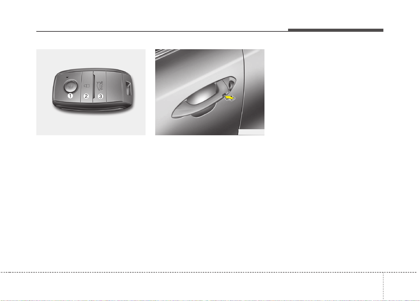
411
Features of your vehicle
SMART KEY (IF EQUIPPED)
Smart key function
1.Door lock
2.Door unlock
3.Tailgate unlock
With a smart key, you can lock or unlock
a door and tailgate and even start the
engine without inserting the key.
The functions of the buttons on a smart
key are similar to the remote keyless
entry. Refer to the “Remote keyless
entry” in this chapter.
Carrying the smart key, you may lock and
unlock the vehicle doors and tailgate.
Also, you may start the engine. Refer to
the following, for more details.
Locking
1. Carry the smart key.
2. Close all doors.
3. Press the button of the outside door
handle.
4. The hazard warning lights will blink
once (the engine hood and tailgate
must be closed). Also, the outside
rearview mirror will automatically fold
if the outside rearview mirror folding
switch is in the AUTO position (if
equipped).
5. Make sure that doors are locked by
pulling the outside door handle.
✽✽
NOTICE
• The button will only operate when the
smart key is within 0.7 m (28 in.) from
the outside door handle.
• Even though you press the outside
door handle button, the doors will not
lock and the chime will sound for 3
seconds if any of following occur:
- The smart key is in the vehicle.
- The engine start/stop button is in
ACC or ON position.
- Any door except the tailgate is
opened.
OJD042001 OJD042008
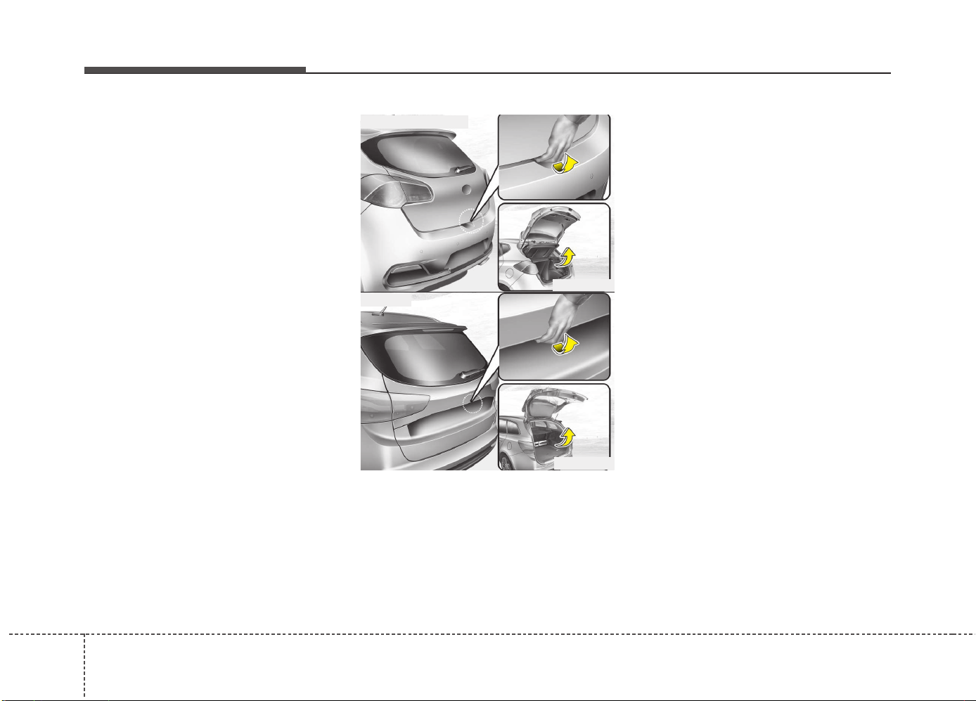
Features of your vehicle
124
Unlocking
1. Carry the smart key.
2.Press the button of the front outside
door handle.
3.All doors will unlock and the hazard
warning lights will blink twice. Also, the
outside rearview mirror will automati-
cally unfold if the outside rearview mir-
ror folding switch is in the AUTO posi-
tion (if equipped).
✽✽
NOTICE
• The button will only operate when the
smart key is within 0.7 m (28 in.) from
the outside door handle.
• When the smart key is recognized in
the area of 0.7 m (28 in.) from the
front outside door handle, other peo-
ple can also open the doors.
• After unlocking all doors, the doors
will lock and the outside rearview mir-
ror will unfold if the outside rearview
mirror folding switch (Type A) is in the
AUTO position (if equipped) unless a
door is opened within 30 seconds.
Tailgate unlocking
1.Carry the smart key.
2.Press the tailgate handle switch.
3.The tailgate will unlock.
✽✽
NOTICE
• Once the tailgate is opened and then
closed, the tailgate will lock automati-
cally.
• The button will only operate when the
smart key is within 0.7 m (28 in.) from
the tailgate handle.
OJD042016
OJD042241
■ 3 Door and 5 Door
■ Wagon
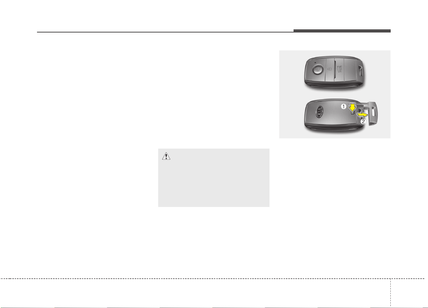
413
Features of your vehicle
Smart key precautions
✽✽
NOTICE
• If, for some reason, you happen to lose
your smart key, you will not be able to
start the engine. Tow the vehicle, if
necessary, we recommend that you
contact an authorized Kia dealer.
• A maximum of 2 smart keys can be
registered to a single vehicle. If you
lose a smart key, we recommend that
you contact an authorized Kia dealer.
• The smart key will not work if any of
the following occurs:
- The smart key is close to a radio
transmitter such as a radio station or
an airport which can interfere with
normal operation of the smart key.
- The smart key is near a mobile two-
way radio system or a cellular
phone.
- Another vehicle’s smart key is being
operated close to your vehicle.
When the smart key does not work
properly, open and close the door with
the mechanical key. If you have a
problem with the smart key, we rec-
ommend that you contact an author-
ized Kia dealer.
(Continued)
(Continued)
• If the smart key is in close proximity
to your cell phone or smart phone, the
signal from the smart key could be
blocked by normal operation of your
cell phone or smart phone. This is
especially important when the phone
is active such as making call, receiving
calls, text messaging, and/or
sending/receiving emails. Avoid plac-
ing the smart key and your cell phone
or smart phone in the same pants or
jacket pocket and maintain adequate
distance between the two devices.
Door lock/unlock in an emer-
gency situation
If the smart key does not operate normal-
ly, you can lock or unlock the doors by
using the mechanical key.
1.Press and hold the release button (1)
and remove the mechanical key (2).
2.Insert the key into the hole of the out-
side door handle. Turn the key toward
the rear of the vehicle to unlock and
toward the front of the vehicle to lock.
3. To reinstall the mechanical key, put the
key into the hole and push it until a
click sound is heard.
CAUTION
Keep the smart key away from
water or any liquid. If the keyless
entry system is inoperative due to
exposure to water or liquids, it will
not be covered by your manufactur-
er’s vehicle warranty.
OJD042002
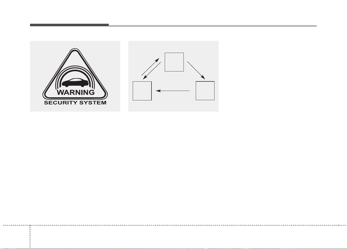
Features of your vehicle
144
Vehicles equipped with a theft alarm sys-
tem will have a label attached to the vehi-
cle with the following words:
1. WARNING
2. SECURITY SYSTEM
This system is designed to provide pro-
tection from unauthorized entry into the
vehicle. This system is operated in three
stages: the first is the "Armed" stage, the
second is the "Theft-alarm" stage, and
the third is the "Disarmed" stage. If trig-
gered, the system provides an audible
alarm with blinking of the hazard warning
lights.
Armed stage
Using the smart key
Park the vehicle and stop the engine.
Arm the system as described below.
1. Turn off the engine.
2. Make sure that all doors, the engine
hood and tailgate are closed and
latched.
3.• Lock the doors by pressing the button
of the front outside door handle with
the smart key in your possession.
After completion of the steps above,
the hazard warning lights will operate
once to indicate that the system is
armed.
If the tailgate or engine hood remains
opened, the hazard warning lights will
not operate and theft-alarm will not
arm. After this, if the tailgate and
engine hood are closed, the hazard
warning lights will blink once and the
theft-alarm will arm.
THEFT-ALARM SYSTEM (IF EQUIPPED)
Armed
stage
Theft-alarm
stage
Disarmed
stage
OJC040170

415
Features of your vehicle
• Lock the doors by pressing the lock
button on the smart key.
After completion of the steps above,
the hazard warning lights will operate
once to indicate that the system is
armed.
If the tailgate or engine hood remains
opened, the hazard warning lights will
not operate and theft-alarm will not
arm. After this, if the tailgate and
engine hood are closed, the hazard
warning lights will blink once and the
theft-alarm will arm.
Using the transmitter
Park the vehicle and stop the engine.
Arm the system as described below.
1.Turn off the engine and remove the
ignition key from the ignition switch.
2.Make sure that all doors, the engine
hood and tailgate are closed and
latched.
3.Lock the doors by pressing the lock
button on the transmitter.
After completion of the steps above, the
hazard warning lights will blink once to
indicate that the system is armed.
If the tailgate or engine hood remains
opened, the hazard warning lights will
not operate and theft-alarm will not arm.
After this, if the tailgate and engine hood
are closed, the hazard warning lights will
blink once and the theft-alarm will arm.
• Do not arm the system until all pas-
sengers have left the vehicle. If the
system is armed while a passen-
ger(s) remains in the vehicle, the
alarm may be activated when the
remaining passenger(s) leave the
vehicle. If any door, tailgate or
engine hood is opened within 30
seconds after entering the armed
stage, the system is disarmed to
prevent unnecessary alarm.
Theft-alarm stage
The alarm will be activated if any of the
following occurs while the system is
armed.
• A front or rear door is opened without
using transmitter or smart key.
• The tailgate is opened without using
transmitter or smart key.
• The engine hood is opened.
The siren will sound and the hazard
warning lights will blink continuously for
27 seconds, unless the system is dis-
armed. To turn off the system, unlock the
doors with the transmitter or smart key.

Features of your vehicle
164
Disarmed stage
The system will be disarmed when:
Transmitter
- The door unlock button is pressed.
- The engine is started.
- The ignition switch is in the “ON” posi-
tion for 30 seconds or more.
Smart key
- The door unlock button is pressed.
- The button of the front outside door is
pressed while carrying the smart key.
- The engine is started.
After the doors are unlocked, the hazard
warning lights will blink twice to indicate
that the system is disarmed.
After pressing the unlock button, if any
door (or tailgate) is not opened within 30
seconds, the system will be rearmed.
✽✽
NOTICE
• Without smart key system
If the system is not disarmed with the
transmitter, insert the key into the
ignition switch and start the engine.
Then the system will be disarmed.
• With smart key system
If the system is not disarmed with the
smart key, open the door with the
mechanical key and start the engine.
Then the system will be disarmed.
• If you lose your keys, we recommend
that you consult an authorized Kia
dealer.
CAUTION
Do not change, alter or adjust the
theft-alarm system because it could
cause the theft-alarm system to
malfunction and we recommend
that the system be serviced by an
authorized Kia dealer.
Malfunctions caused by improper
alterations, adjustments or modifi-
cations to the theft-alarm system
are not covered by your vehicle
manufacturer warranty.
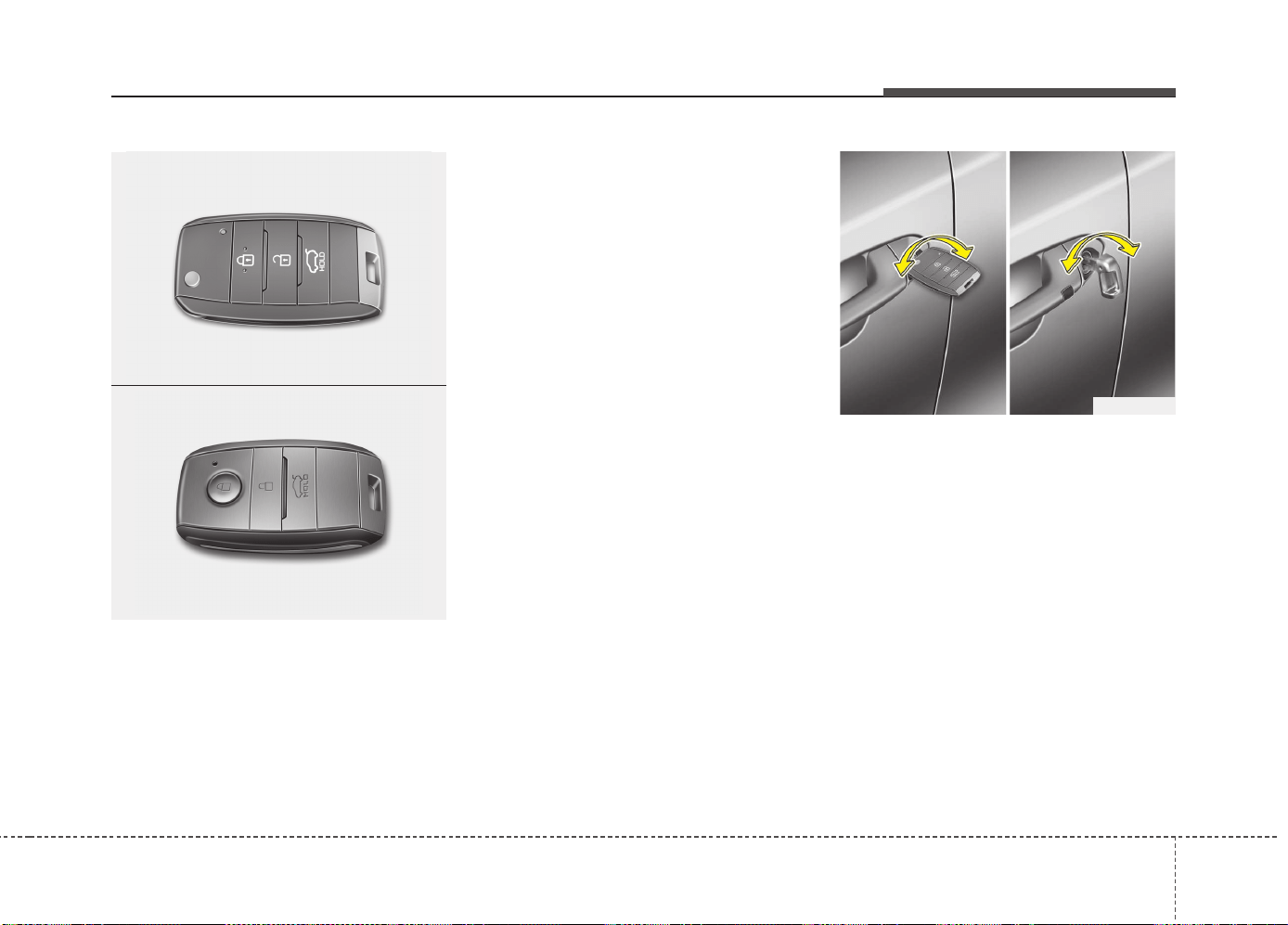
417
Features of your vehicle
Operating door locks from out-
side the vehicle
Transmitter/Smart key
• Doors can be locked and unlocked with
the transmitter or smart key.
• Doors can be locked and unlocked by
pressing the button of the outside door
handle with the smart key in your pos-
session. (vehicles equipped with smart
key system)
• Once the doors are unlocked, they may
be opened by pulling the door handle.
• When closing the door, push the door
by hand. Make sure that doors are
closed securely.
Mechanical key
• If the transmitter or smart key does not
operate normally, you can lock or unlock
the doors by the mechanical key.
Insert the key into the key hole of the
outside door handle.Turn the key toward
the rear of the vehicle to unlock and
toward the front of the vehicle to lock.
• If you lock/unlock the driver’s door with
a key while the power door lock switch
does not operate normally, only the dri-
ver’s door will lock/unlock.
• Once the door is unlocked, it may be
opened by pulling the door handle.
• When closing the door, push the door
by hand. Make sure that doors are
closed securely.
DOOR LOCKS
OJD043010
ORP042235
■ Type A
OJD042001
■ Type B
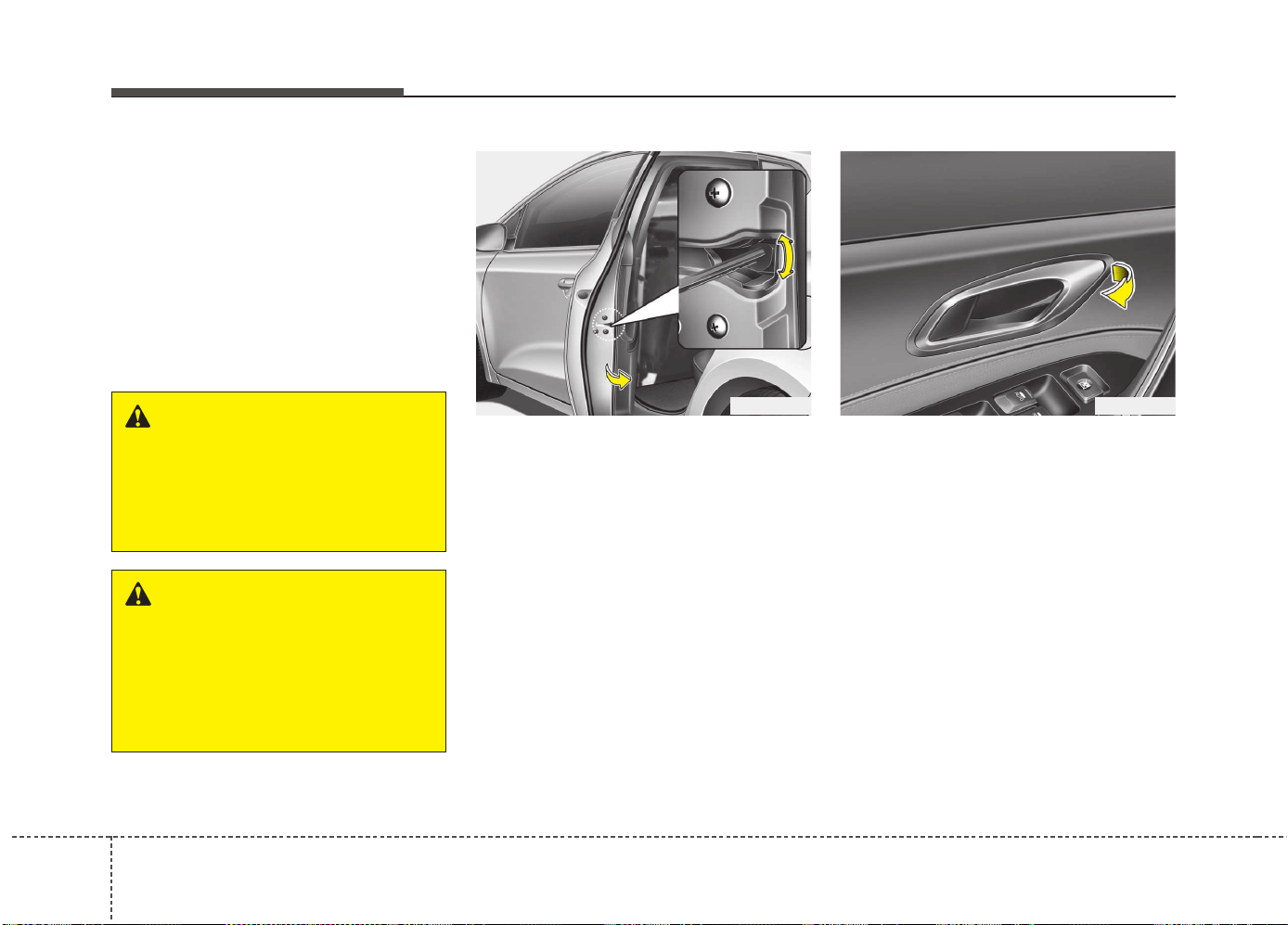
Features of your vehicle
184
✽✽
NOTICE
• In cold and wet climates, door lock
and door mechanisms may not work
properly due to freezing conditions.
• If the door is locked/unlocked multi-
ple times in rapid succession with
either the vehicle key or door lock
switch, the system may stop operating
temporarily in order to protect the
circuit and prevent damage to system
components.
In case of an emergency
(5 Door and wagon)
If the power door lock switch does not
operate electrically, the only way to lock
the door(s) is with the mechanical key
from the outside key hole.
You can lock the doors without the out-
side key hole as follows:
1. Open the door.
2. Insert the key into the emergency door
lock hole and turn the key horizontally
to lock.
3. Close the door securely.
Operating door locks from inside
the vehicle
With the door handle
Driver’s door and front passanger’s door
(if equipped)
If the inner door handle is pulled when
the door is locked, the door will unlock
and open.
Rear door (if equipped)
If the inner door handle is pulled once
when the door is locked, the door will
unlock.
If the inner door handle is pulled once
more, the door will open.
OJD042012
LL
LL
oo
oo
cc
cc
kk
kk
OJD042013
UU
UU
nn
nn
ll
ll
oo
oo
cc
cc
kk
kk
WARNING
• If you don't close the door secure-
ly, the door may open again.
• Be careful that someone's body
and hands are not trapped when
closing the door.
WARNING
If people must spend a longer time
in the vehicle while it is very hot or
cold outside, there is risk of
injuries or danger to life. Do not
lock the vehicle from the outside
when there are people in it.
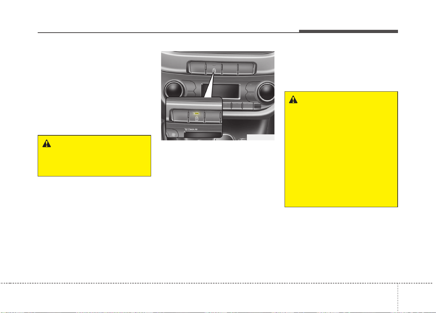
419
Features of your vehicle
If a power door lock ever fails to function
while you are in the vehicle, try one or
more of the following techniques to exit:
• Operate the door unlock feature
repeatedly (both electronic and manu-
al) while simultaneously pulling on the
door handle.
• Operate the other door locks and han-
dles, front and rear.
• Lower a front window and use the key
to unlock the door from outside.
With central door lock/unlock switch
It is operated by pressing the door lock/
unlock switch.
• When you press the central door lock
switch, all vehicle doors will lock and
the indicator light on the switch will illu-
minate.
• If any door is opened when the switch
is pressed, all doors will not lock.
• If any door is unlocked, the indicator of
the central door lock switch will go off.
• When you press the central door
unlock switch, all vehicle doors will
unlock.
✽✽
NOTICE
Once the doors are locked with the
transmitter or smart key, the doors can-
not be unlocked with the central door
lock/unlock switch.
OJD042014
WARNING
Do not pull the inner door handle of
driver’s(or passenger’s) door while
the vehicle is moving.
WARNING - Doors
• The doors should always be fully
closed and locked while the vehi-
cle is in motion to prevent acci-
dental opening of the door.
Locked doors will also discour-
age potential intruders when the
vehicle stops or slows down.
• Be careful when opening doors
and watch for vehicles, motorcy-
cles, bicycles or pedestrians
approaching the vehicle in the
path of the door. Opening a door
when something is approaching
can cause damage or injury.
Features of your vehicle
204
Deadlocks (if equipped)
Some vehicles are equipped with a
deadlock system. Deadlocks prevent
opening of a door from either inside or
outside the vehicle once the deadlocks
have been activated providing an addi-
tional measure of vehicle security.
To lock the vehicle using the deadlock
function, the doors must be locked by
using the transmitter or smart key. To
unlock the vehicle, the transmitter or
smart key must be used again.
Door lock/unlock features
Impact sensing door unlock system
All doors will automatically unlock when
an impact causes the air bags to deploy.
Speed sensing door lock system
(if equipped)
All doors will automatically lock after the
vehicle speed exceeds 15 km/h.
Engine off door unlock system
(if equipped)
All doors will automatically unlock:
Without smart key system
When the key is removed from the igni-
tion switch.
With smart key system
When the engine start/stop button is in
the OFF position.
Shift lever door lock/unlock system
• All doors will automatically lock when
the shift lever is moved out of P (Park).
• All doors will automatically unlock when
the shift lever is moved into P (Park).
You can activate or deactivate the auto
door lock/unlock features in the vehicle.
Refer to "User setting" in this chapter.
WARNING
Do not lock the doors with the
transmitter or the smart key with
anybody left in the vehicle. The pas-
senger in the vehicle cannot unlock
the doors with the door lock button.
For example, if the door is locked
with the transmitter, the passenger
in the vehicle cannot unlock the
door without the transmitter.
WARNING - Unlocked
vehicles
Leaving your vehicle unlocked can
invite theft or possible harm to you
or others from someone hiding in
your vehicle while you are gone.
Always remove the ignition key,
engage the parking brake, close all
windows and lock all doors when
leaving your vehicle unattended.
WARNING - Unattended
children
An enclosed vehicle can become
extremely hot, causing death or
severe injury to unattended chil-
dren or animals who cannot escape
the vehicle. Furthermore, children
might operate features of the vehi-
cle that could injure them, or they
could encounter other harm, possi-
bly from someone gaining entry to
the vehicle. Never leave children or
animals unattended in your vehicle.
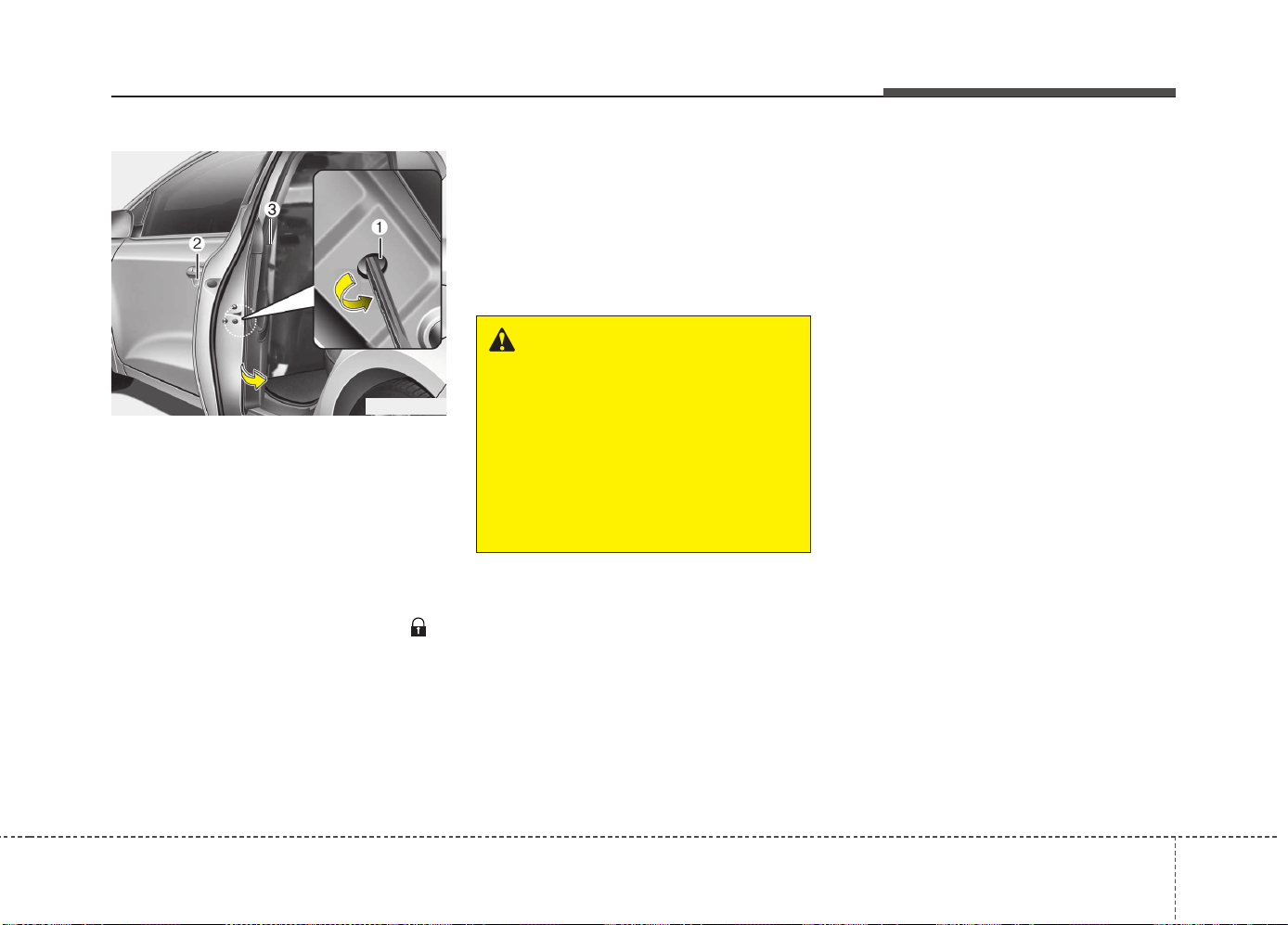
421
Features of your vehicle
Child-protector rear door lock
(5 Door and wagon)
The child safety lock is provided to help
prevent children from accidentally open-
ing the rear doors from inside the vehicle.
The rear door safety locks should be used
whenever children are in the vehicle.
1. Open the rear door.
2. Insert a key (or screwdriver) into the
hole (1) and turn it to the “lock( )”
position. When the child safety lock is
in the lock position, the rear door will
not open even though the inner door
handle (3) is pulled inside the vehicle.
3. Close the rear door.
To open the rear door, pull the outside
door handle (2).
Even though the doors may be unlocked,
the rear door will not open by pulling the
inner door handle (3) until rear door child
safety lock is unlocked.
WARNING - Rear door
locks
If children accidentally open the
rear doors while the vehicle is in
motion, they could fall out and be
severely injured or killed. To pre-
vent children from opening the rear
doors from the inside, the rear door
safety locks should be used when-
ever children are in the vehicle.
OJD042015
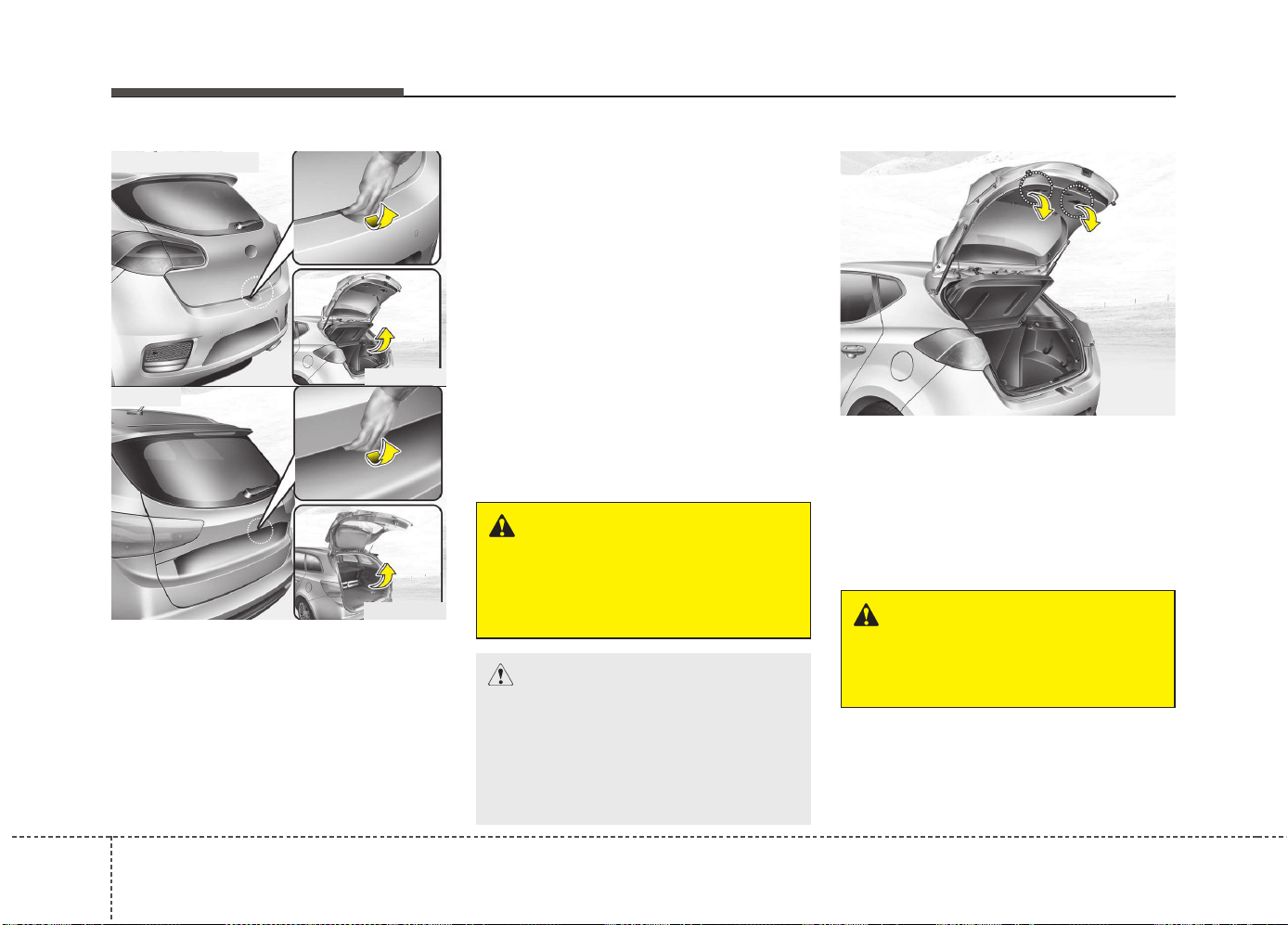
Features of your vehicle
224
Opening the tailgate
• The tailgate is locked or unlocked
when all doors are locked or unlocked
with the key, transmitter, smart key or
central door lock/unlock switch.
• Only the tailgate is unlocked if the tail-
gate unlock button on the transmitter or
smart key is pressed for approximately
1 second or the tailgate handle switch
is pressed with the smart key in your
possession.
• If unlocked, the tailgate can be opened
by pressing the handle and pulling it up.
• Once the tailgate is opened and then
closed, the tailgate locks automatically.
(All doors must be locked.)
✽✽
NOTICE
In cold and wet climates, door lock and
door mechanisms may not work proper-
ly due to freezing conditions.
❈ The actual luggage room in the vehicle may
differ from the illustration.
Closing the tailgate
Lower and push down the tailgate firmly.
Make sure that the tailgate is securely
latched.
TAILGATE
OJD045016
OJD042241
WARNING
The tailgate swings upward. Make
sure no objects or people are near
the rear of the vehicle when open-
ing the tailgate.
CAUTION
Make certain that you close the tail-
gate before driving your vehicle.
Possible damage may occur to the
tailgate lift cylinders and attaching
hardware if the tailgate is not
closed prior to driving.
WARNING
Make sure your hands, feet and other
parts of your body are safely out of
the way before closing the tailgate.
OJD042087
■ 3 Door and 5 Door
■ Wagon
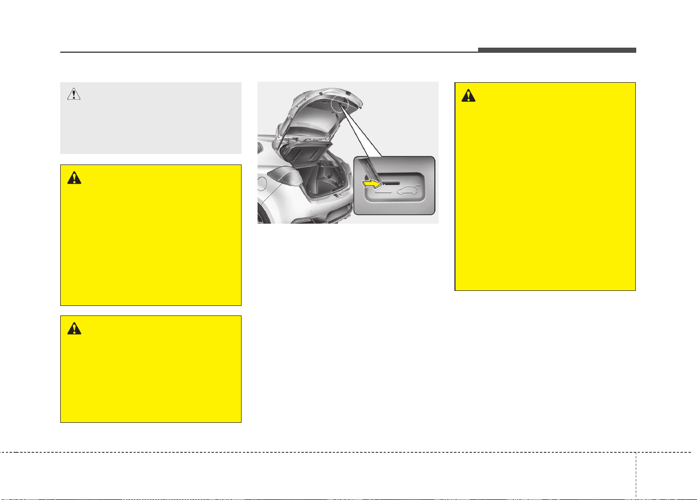
423
Features of your vehicle
❈ The actual luggage room in the vehicle may
differ from the illustration.
Emergency tailgate safety release
Your vehicle is equipped with the emer-
gency tailgate safety release lever locat-
ed on the bottom of the tailgate. When
someone is inadvertently locked in the
luggage compartment. The tailgate can
be opened by doing as follows:
1. Input the machanical key into the hole.
2. Push the machanical key to the right.
3. Push up the tailgate.
WARNING - Exhaust
fumes
If you drive with the tailgate
opened, you will draw dangerous
exhaust fumes into your vehicle
which can cause serious injury or
death to vehicle occupants.
If you must drive with the tailgate
opened, keep the air vents and all
windows open so that additional
outside air comes into the vehicle.
WARNING - Rear cargo
area
Occupants should never ride in the
rear cargo area where no restraints
are available. To avoid injury in the
event of an accident or sudden
stops, occupants should always be
properly restrained.
OJD042017
WARNING
• For emergencies, be fully aware
of the location of the emergency
tailgate safety release lever in the
vehicle and how to open the tail-
gate if you are accidentally locked
in the luggage compartment.
• No one should be allowed to
occupy the luggage compartment
of the vehicle at any time. The
luggage compartment is a very
dangerous location in the event
of a crash.
• Use the release lever for emer-
gencies only. Use with extreme
caution, especially while the vehi-
cle is in motion.
CAUTION
Make sure nothing is near the tail-
gate latch and striker while closing
the tailgate. It may damage the tail-
gate's latch.
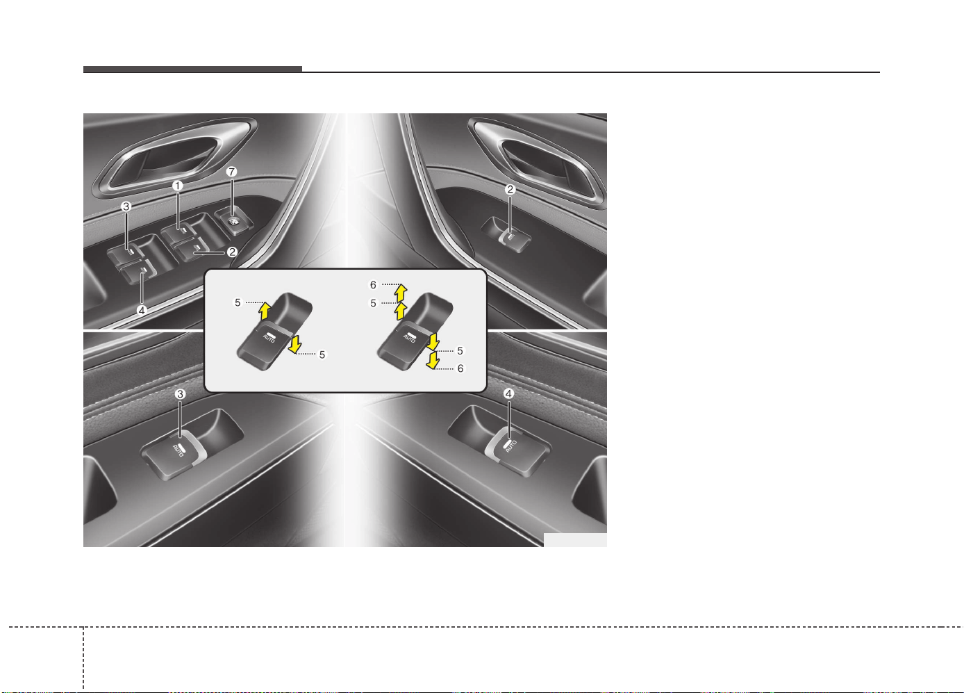
Features of your vehicle
244
(1) Driver’s door power window switch
(2) Front passenger’s door power win-
dow switch
(3) Rear door (left) power window
switch* (for 5 Door and wagon)
(4) Rear door (right) power window
switch* (for 5 Door and wagon)
(5) Window opening and closing
(6) Automatic power window up*/down*
(7) Power window lock switch*
*: if equipped
✽✽
NOTICE
In cold and wet climates, power win-
dows may not work properly due to
freezing conditions.
WINDOWS
OJD045018
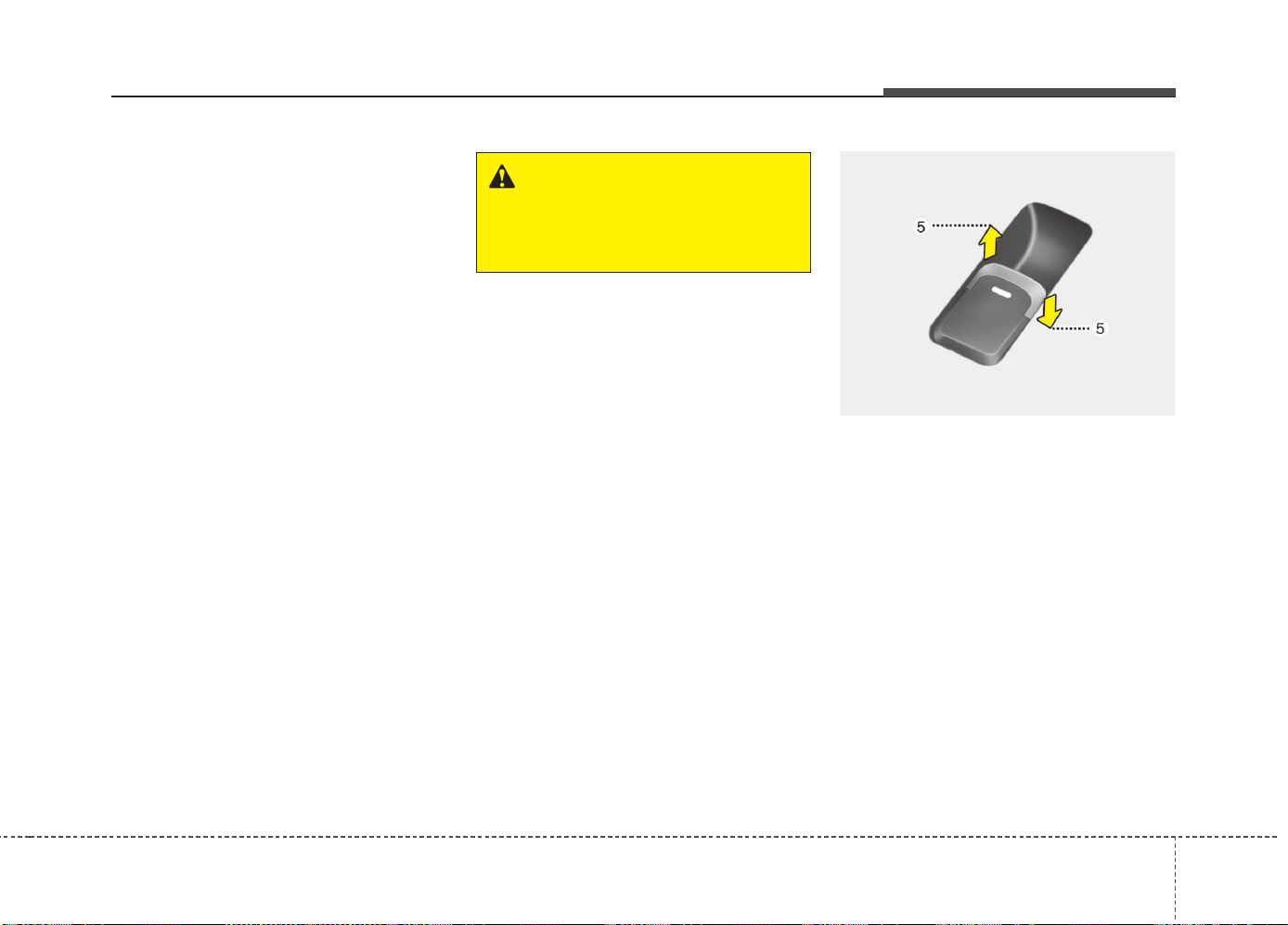
425
Features of your vehicle
Power windows
The ignition switch must be in the ON
position for power windows to operate.
Each door has a power window switch
that controls the door’s window. The dri-
ver’s door has a master power window
switch that controls all the windows in the
vehicle. Also, the driver has a power win-
dow lock switch which can block the
operation of rear passenger windows.
The power windows can be operated for
approximately 30 seconds after the igni-
tion key is removed or turned to the ACC
or LOCK position. However, if the front
doors are opened, the power windows
cannot be operated even within the 30
seconds period.
✽✽
NOTICE
While driving with the rear windows
down or with the sunroof (if equipped) in
an open (or partially open position), your
vehicle may demonstrate a wind buffet-
ing or pulsation noise. This noise is a
normal occurrence and can be reduced
or eliminated by taking the following
actions. If the noise occurs with one or
both of the rear windows down, partially
lower both front windows approximate-
ly one inch. If you experience the noise
with the sunroof open, slightly reduce the
size of the sunroof opening.
Window opening and closing
Type A
To open or close a window, press down
or pull up the front portion of the corre-
sponding switch to the first detent posi-
tion (5).
WARNING
Do not install any accessories in
the area of windows. It may impact
jam protection.
OJD045019
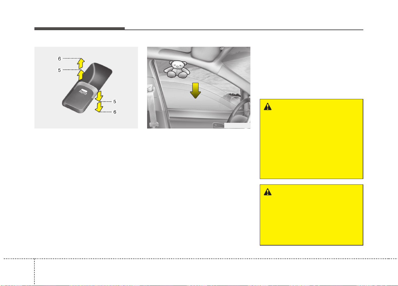
Features of your vehicle
264
Type B - Auto up/down window
(if equipped)
Pressing or pulling up the power window
switch momentarily to the second detent
position (6) completely lowers or lifts the
window even when the switch is released.
To stop the window at the desired position
while the window is in operation, pull up
or press down and release the switch.
✽✽
NOTICE
If the power window does not operate
normally, the automatic power window
system must be reset as follows:
1. Turn the ignition switch to the ON
position.
2. Close the window and continue
pulling up the power window switch
for at least 1 second after the window
is completely closed.
Automatic reversal (for type B window)
If the upward movement of the window is
blocked by an object or part of the body,
the window will detect the resistance and
will stop upward movement. The window
will then lower approximately 30 cm (11.8
in.) to allow the object to be cleared.
If the window detects the resistance
while the power window switch is pulled
up continuously, the window will stop
upward movement then lower approxi-
mately 2.5 cm (1 in.). And if the power
window switch is pulled up continuously
again within 5 seconds after the window
is lowered by the automatic window
reversal feature, the automatic window
reversal will not operate.
✽✽
NOTICE
The automatic reverse feature is only
active when the “auto up” feature is used
by fully pulling up the switch. The auto-
matic reverse feature will not operate if
the window is raised using the halfway
position on the power window switch.
OUN026013
OJD045020
WARNING
Always check for obstructions
before raising any window to avoid
injuries or vehicle damage. If an
object less than 4 mm (0.16 in.) in
diameter is caught between the
window glass and the upper win-
dow channel, the automatic reverse
window may not detect the resist-
ance and will not stop and reverse
direction.
WARNING
The automatic reverse feature
doesn’t activate while resetting
power window system. Make sure
body parts or other objects are
safely out of the way before closing
the windows to avoid injuries or
vehicle damage.
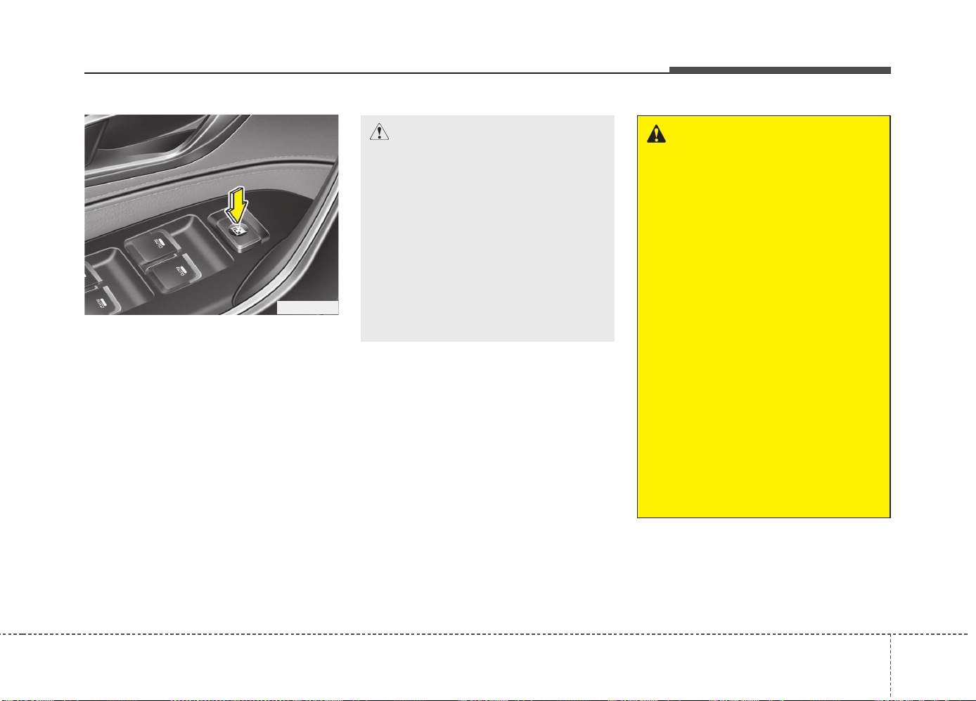
427
Features of your vehicle
Power window lock button
(for 5 Door and wagon) (if equipped)
The driver can disable the power window
switches on the rear passengers' doors
by pressing the power window lock
switch to the lock position (pressed).
When the power window lock switch is
pressed:
• The driver's master control can oper-
ate all the power windows.
• The front passenger's control can
operate the front passenger's power
window.
• The rear passenger's control cannot
operate the rear passenger's power
window.
CAUTION
• To prevent possible damage to the
power window system, do not open
or close two windows or more at
the same time.This will also ensure
the longevity of the fuse.
• Never try to operate the main
switch on the driver's door and
the individual door window
switch in opposing directions at
the same time. If this is done, the
window will stop and cannot be
opened or closed.
WARNING - Windows
• NEVER leave the keys in your
vehicle with unsupervised chil-
dren when the engine is running.
• NEVER leave any child unattend-
ed in the vehicle. Even very
young children may inadvertently
cause the vehicle to move, entan-
gle themselves in the windows,
or otherwise injure themselves or
others.
• Always double check to make sure
all arms, hands, head and other
obstructions are safely out of the
way before closing a window.
• Do not allow children to play with
the power windows. Keep the dri-
ver’s door power window lock
switch in the LOCK position
(pressed). Serious injury can
result from unintentional window
operation by the child.
• Do not extend face or arms out-
side the window while driving.
OJD045021
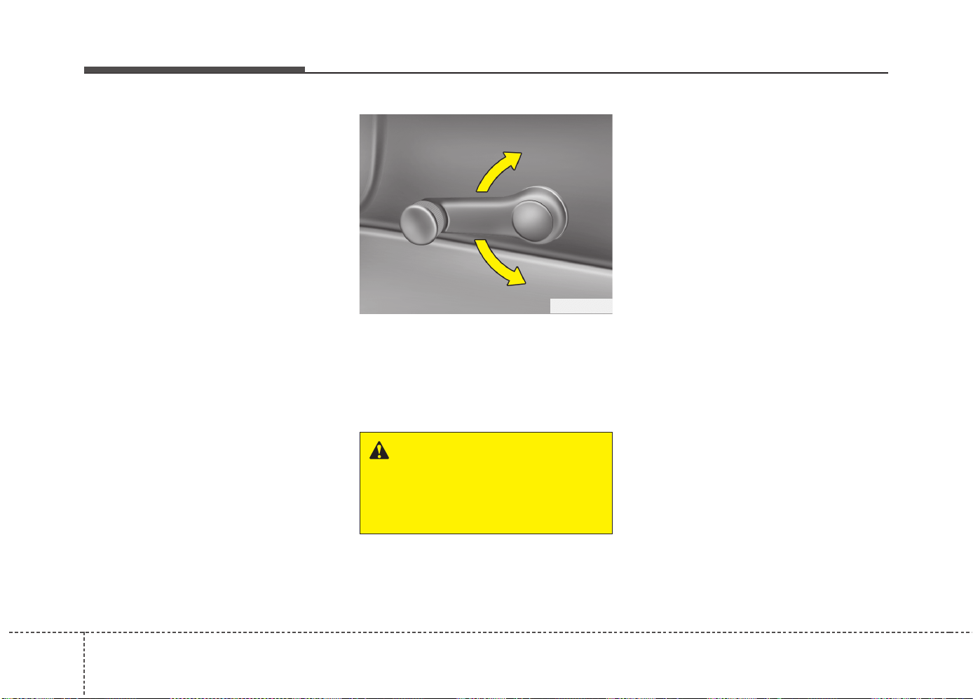
Features of your vehicle
284
If the window cannot be close because it
is blocked by objects, remove the objects
and close the window.
Manual windows
(for 5 Door and wagon)
(if equipped)
To raise or lower the window, turn the
window regulator handle clockwise or
counterclockwise.
OED036088
WARNING
When opening or closing the win-
dows, make sure your passenger's
arms, hands and body are safely
out of the way.
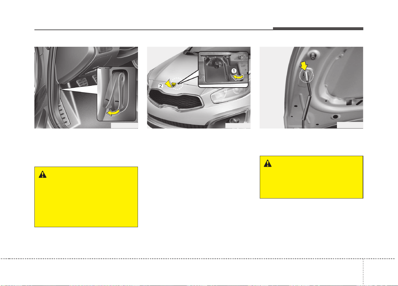
429
Features of your vehicle
Opening the hood
1. Pull the release lever to unlatch the
hood. The hood should pop open
slightly.
2. Go to the front of the vehicle, raise the
hood slightly, push safety lever inside
of the hood center and lift the hood.
3. Pull out the support rod.
4. Hold the hood opened with the support
rod.
HOOD
OJD042022
WARNING
Open the hood after turning off the
engine on a flat surface, shifting
the shift lever to the P(Park) posi-
tion for automatic transaxle and to
the 1(First) gear or R(Reverse) for
manual transaxle, and setting the
parking brake.
OJD045023
WARNING - Hot parts
Be very careful not to touch the
support rod when the engine and
parts are hot. You could get burned
or get seriously injured.
OJD042024
Features of your vehicle
304
Closing the hood
1. Before closing the hood, check the fol-
lowing:
• All filler caps in engine compartment
must be correctly installed.
• Gloves, rags or any other com-
bustible material must be removed
from the engine compartment.
2. Return the support rod to its clip to
prevent it from rattling.
3.
Lower the hood halfway and push
down to securely lock in place.
• Then double check to be sure the
hood is secure.
• If the hood can be lifted with a slight
force, open the hood again and close
it more firmly
WARNING - Hood
• Before closing the hood, ensure
that all obstructions are removed
from the hood opening. Closing
the hood with an obstruction
present in the hood opening may
result in property damage or
severe personal injury.
• Do not leave gloves, rags or any
other combustible material in the
engine compartment. Doing so
may cause a heat-induced fire.
WARNING
• Always double check to be sure
that the hood is firmly latched
before driving away. If it is not
latched, the hood could fly open
while the vehicle is being driven,
causing a total loss of visibility,
which might result in an accident.
• The support rod must be inserted
completely into the hole whenev-
er you inspect the engine com-
partment. This will prevent the
hood from falling and possibly
injuring you.
• Do not move the vehicle with the
hood raised. The view will be
blocked and the hood could fall
or be damaged.
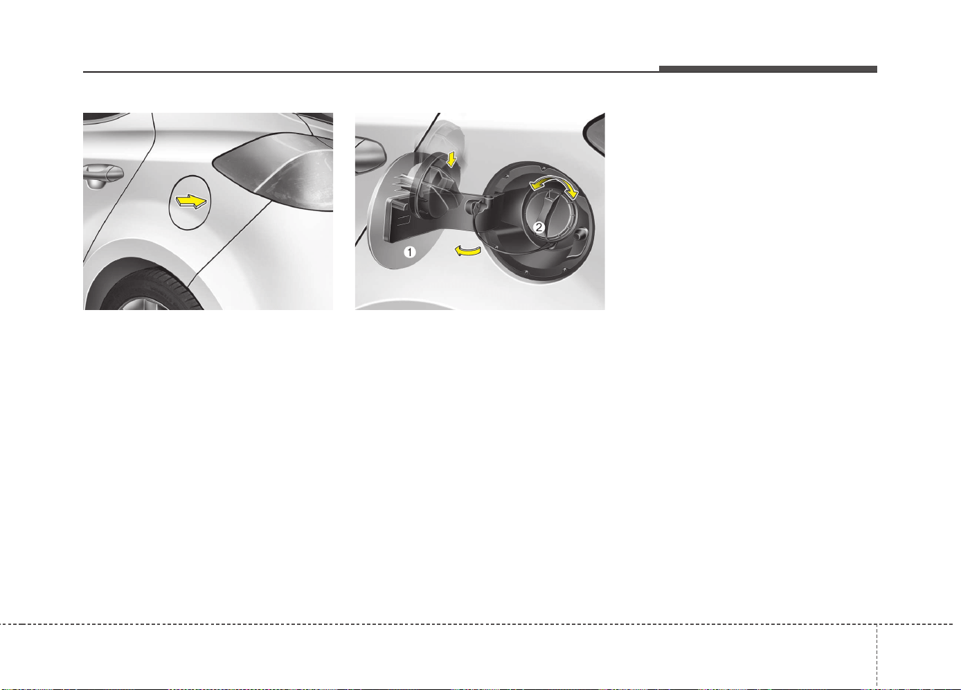
431
Features of your vehicle
Opening the fuel filler lid
1. To open the lid, press the center edge
of the lid when all doors are unlocked.
✽✽
NOTICE
The lid will open and close only when all
doors are unlocked.
2. Fully open the lid (1).
3. To open the cap, turn it counterclock-
wise (2).
4. Refuel as needed.
✽✽
NOTICE
If the fuel-filler lid does not open because
ice has formed around it, tap lightly or
push on the lid to break the ice and
release the lid. Do not pry on the lid. If
necessary, spray around the lid with an
approved de-icer fluid (do not use radia-
tor anti-freeze) or move the vehicle to a
warm place and allow the ice to melt.
Closing the fuel filler lid
1. To install the cap, turn it clockwise until
it “clicks”. This indicates that the cap is
securely tightened.
2. To close the lid, press the edge of the
lid. Make sure it is securely closed.
FUEL FILLER LID
OJD042025
OJD042026
Features of your vehicle
324
WARNING - Refueling
• If pressurized fuel sprays out, it
can cover your clothes or skin
and thus subject you to the risk
of fire and burns. Always remove
the fuel cap carefully and slowly.
If the cap is venting fuel or if you
hear a hissing sound, wait until
the condition stops before com-
pletely removing the cap.
• Do not "top off" after the nozzle
automatically shuts off when
refueling.
• Always check that the fuel cap is
installed securely to prevent fuel
spillage in the event of an acci-
dent.
(Continued)
• Do not get back into a vehicle
once you have begun refueling
since you can generate static
electricity by touching, rubbing
or sliding against any item or fab-
ric (polyester, satin, nylon, etc.)
capable of producing static elec-
tricity. Static electricity discharge
can ignite fuel vapors resulting in
rapid burning. If you must re-
enter the vehicle, you should
once again eliminate potentially
dangerous static electricity dis-
charge by touching a metal part
of the vehicle, away from the fuel
filler neck, nozzle or other gaso-
line source.
• When using an approved
portable fuel container, be sure to
place the container on the
ground prior to refueling. Static
electricity discharge from the
container can ignite fuel vapors
causing a fire. Once refueling has
begun, contact with the vehicle
should be maintained until the
filling is complete.
(Continued)
WARNING - Refueling dan-
gers
Automotive fuels are flammable
materials. When refueling, please
note the following guidelines care-
fully. Failure to follow these guide-
lines may result in severe personal
injury, severe burns or death by fire
or explosion.
• Read and follow all warning post-
ed at the gas station facility.
• Before refueling note the location
of the Emergency Gasoline Shut-
Off, if available, at the gas station
facility.
• Before touching the fuel nozzle,
you should eliminate potentially
dangerous static electricity dis-
charge by touching another metal
part of the vehicle, a safe dis-
tance away from the fuel filler
neck, nozzle, or other gas source.
(Continued)
433
Features of your vehicle
(Continued)
Use only portable plastic fuel
containers designed to carry and
store gasoline.
• Do not use cellular phones while
refueling. Electric current and/or
electronic interference from cel-
lular phones can potentially
ignite fuel vapors causing a fire.
• When refueling, always shut the
engine off. Sparks produced by
electrical components related to
the engine can ignite fuel vapors
causing a fire. Once refueling is
complete, check to make sure the
filler cap and filler door are
securely closed, before starting
the engine.
• DO NOT use matches or a lighter
and DO NOT SMOKE or leave a lit
cigarette in your vehicle while at
a gas station especially during
refueling. Automotive fuel is
highly flammable and can, when
ignited, result in fire.
(Continued)
(Continued)
• If a fire breaks out during refuel-
ing, leave the vicinity of the vehi-
cle, and immediately contact the
manager of the gas station and
then contact the local fire depart-
ment. Follow any safety instruc-
tions they provide.
CAUTION
• Make sure to refuel your vehicle
according to the "Fuel require-
ments" suggested in chapter 1.
• If the fuel filler cap requires
replacement, please make sure
that you use parts designed for
replacement in your vehicle. An
incorrect fuel filler cap can result
in a serious malfunction of the
fuel system or emission control
system. For more detailed infor-
mation, we recommend that you
contact an authorized Kia dealer.
• Do not spill fuel on the exterior
surfaces of the vehicle. Any type
of fuel spilled on painted surfaces
may damage the paint.
• After refueling, make sure the fuel
cap is installed securely to pre-
vent fuel spillage in the event of
an accident.
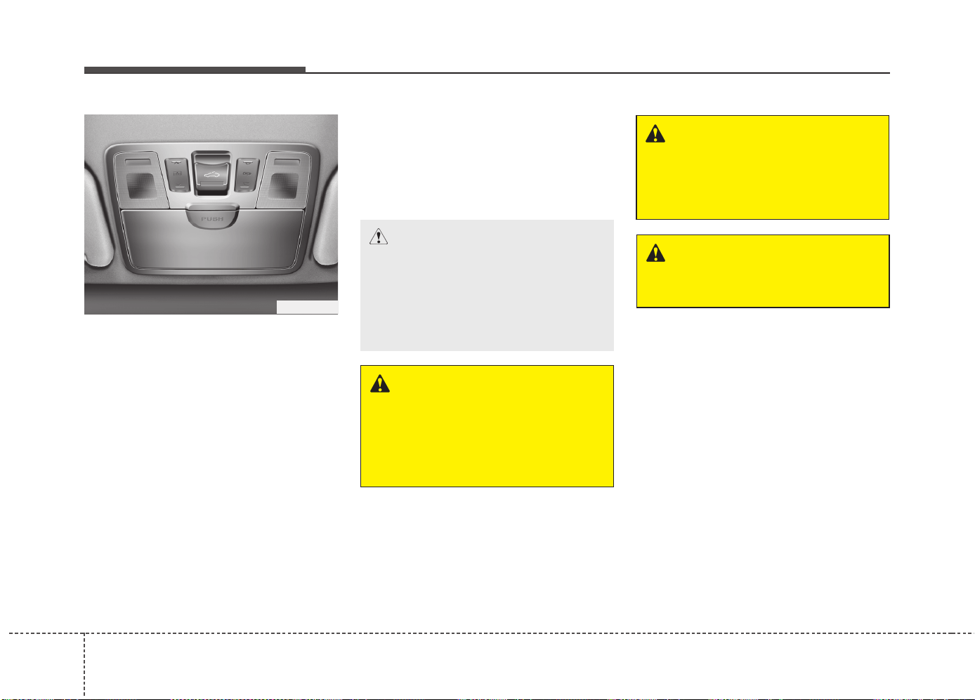
Features of your vehicle
344
If your vehicle is equipped with a sunroof,
you can slide or tilt your sunroof with the
sunroof control lever located on the over-
head console.
The sunroof can only be opened, closed,
or tilted when the ignition switch is in the
ON position.
• In cold and wet climates, the sunroof
may not work properly due to freezing
conditions.
• After the vehicle is washed or in a rain-
storm, be sure to wipe off any water that
is on the sunroof before operating it.
PANORAMA SUNROOF (IF EQUIPPED)
CAUTION - Sunroof control
lever
Do not continue to move the sun-
roof control lever after the sunroof
is fully opened, closed, or tilted.
Damage to the motor or system
components could occur.
OJD042027
WARNING
Never adjust the sunroof or sun-
shade while driving. This could
result in loss of control and an acci-
dent that may cause death, serious
injury, or property damage.
WARNING
In order to prevent accidental oper-
ation of the sunroof, especially by a
child, do not let a child operate the
sunroof.
WARNING
Do not sit on the top of the vehicle.
It may cause vehicle damage.
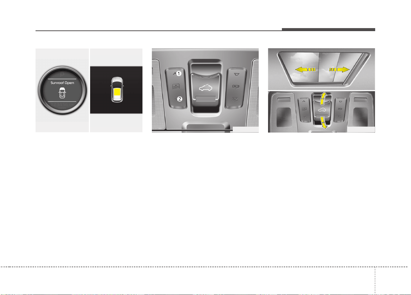
435
Features of your vehicle
Sunroof open warning
(if equipped)
If the driver removes the ignition key
(smart key: turns off the engine) and
opens the driver-side door when the sun-
roof is not fully closed, the warning chime
will sound for approximately 7 seconds
and a warning message will appear on
the LCD display.
Close the sunroof securely when leaving
your vehicle.
Sunshade
• To open the sunshade, press the sun-
shade control switch(1).
• To close the sunshade when the sun-
roof glass is closed.
- Press the sunshade control switch(2).
- Push the sunroof control lever for-
ward or pull it down.
To stop the sliding at any point, press the
sunshade control switch momentarily.
Sliding the sunroof
When the sunshade is closed
If you pull the sunroof control lever back-
ward, the sunshade will slide all the way
open then the sunroof glass will slide all
the way open. To stop the sunroof move-
ment at any point, pull or push the sun-
roof control lever momentarily.
When the sunshade is opened
If you pull the sunroof control lever back-
ward, the sunroof glass will slide all the
way open. To stop the sunroof movement
at any point, pull or push the sunroof con-
trol lever momentarily.
OJD042029
OJD042028OJD042078/OJD045215
■ Supervision■ Normal vision
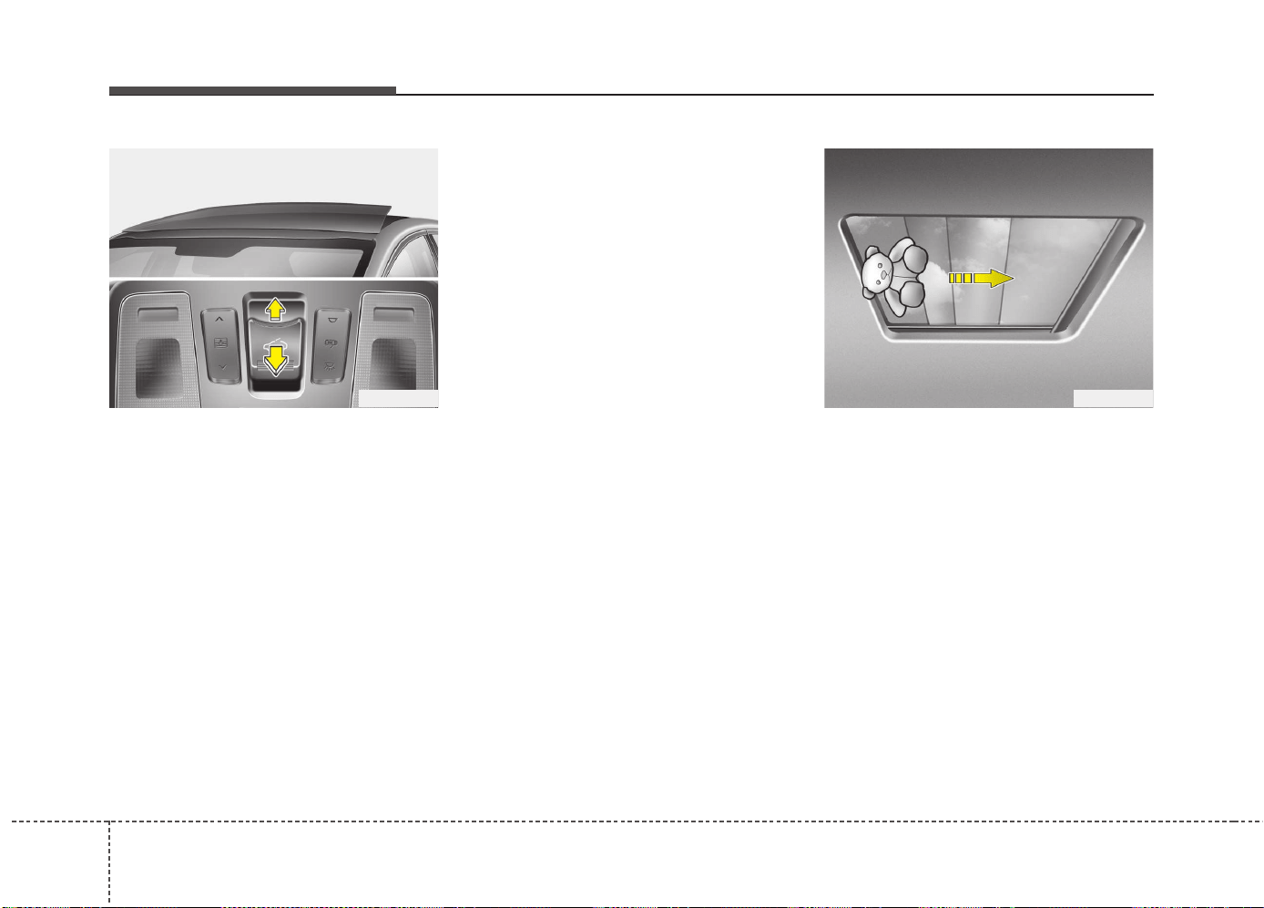
Features of your vehicle
364
Tilting the sunroof
When the sunshade is closed
If you push the sunroof control lever
upward, the sunshade will slide all the
way open then the sunroof glass will tilt.
To stop the sunroof movement at any
point, pull or push the sunroof control
lever momentarily.
When the sunshade is opened
If you push the sunroof control lever
upward, the sunroof glass will tilt.
To stop the sunroof movement at any
point, pull or push the sunroof control
lever momentarily.
Closing the sunroof
To close the sunroof glass with the
sunshade
Push the sunroof control lever forward or
full it down.
The sunroof glass will close.
Then to close sunshade
- Press the sunshade control switch(2).
- Push the sunroof control lever forward
or full it down
To stop the sunroof movement at any
point, pull or push the sunroof control
lever momentarily.
Automatic reversal
If an object or part of the body is detect-
ed while the sunroof glass or sunshade is
closing automatically, it will reverse the
direction, and then stop.
The auto reverse function does not work
if a tiny obstacle is between the sliding
glass or sunshade and the sunroof sash.
You should always check that all passen-
gers and objects are away from the sun-
roof before closing it.
OYF049215OJD042030
437
Features of your vehicle
Resetting the sunroof
Whenever the vehicle battery is discon-
nected or discharged, or related fuse is
blown, you must reset your sunroof sys-
tem as follows:
1.Turn the engine on and close the sun-
roof glass and sunshade completely.
2.Release the control lever.
3. Push the sunroof control lever forward in
the direction of close (about 10 seconds)
until the sunroof operates as follows;
SUNSHADE OPEN → TILT OPEN
Then, release the control lever.
4.Push the sunroof control lever forward
in the direction of close until the sun-
roof operates as follows;
SUNSHADE & SLIDE OPEN SIMUL-
TANEOUSLY → SLIDE CLOSE →
SUNSHADE CLOSE
Then, release the control lever.
When this is complete, the sunroof
system is reset.
For more detailed information, we recom-
mend that you contact an authorized Kia
dealer.
CAUTION
• Periodically remove any dirt that
may accumulate on the guide rail.
• If you try to open the sunroof when
the temperature is below freezing
or when the sunroof is covered
with snow or ice, the glass or the
motor could be damaged.
• If you drive with the sunroof opened
right after a car wash or rain, water
may get inside the vehicle.
WARNING - Sunroof
• Be careful that someone’s head,
hands and body are not trapped by
a closing sunroof.
• Do not extend the face, neck, arms
or body outside through an
opened sunroof while driving.
• Make sure your hands and face are
safely out of the way before clos-
ing a sunroof.
• A panorama sunroof is made of
glass, therefore it may break in an
accident. If you do not have your
seat belt on, you may stick out of
the broken glass and get injured or
killed. For all passengers safety,
have an appropriate protection on.
(ex. seat belt, CRS, etc.)

Features of your vehicle
384
✽✽
NOTICE
If you do not reset the sunroof, it may
not work properly.

439
Features of your vehicle
STEERING WHEEL
Electronic power steering
Power steering uses the motor to assist
you in steering the vehicle. If the engine
is off or if the power steering system
becomes inoperative, the vehicle may
still be steered, but it will require
increased steering effort.
The electronic power steering is con-
trolled by the power steering control unit
which senses the steering wheel torque
and vehicle speed to command the
motor.
The steering effort becomes heavier as
the vehicle’s speed increases and
becomes lighter as the vehicle’s speed
decreases for better control of the steer-
ing wheel.
Should you notice any change in the
effort required to steer during normal
vehicle operation, we recommend that
the system be checked by an authorized
Kia dealer.
✽✽
NOTICE
The following symptoms may occur dur-
ing normal vehicle operation:
• The EPS warning light does not illu-
minate.
• The steering effort is high immediate-
ly after turning the ignition switch on.
This happens as the system performs
the EPS system diagnostics. When the
diagnostics is completed, the steering
wheel will return to its normal condi-
tion.
• A click noise may be heard from the
EPS relay after the ignition switch is
turned to the ON or LOCK/OFF posi-
tion.
• Motor noise may be heard when the
vehicle is at a stop or at a low driving
speed.
• The steering effort increases if the
steering wheel is rotated continuously
when the vehicle is not in motion.
However, after a few minutes, it will
return to its normal conditions.
(Continued)
(Continued)
• If an error is detected in the electric
power steering system, EPS will stop
assisting driver in steering the vehicle to
prevent accidents and the warning light
on the cluster will illuminate or blink.
We recommend that the system be
checked by an authorized Kia dealer as
soon as possible.
• When you operate the steering wheel in
low temperature, abnormal noise could
occur. If temperature rises, the noise
will disappear. This is a normal condi-
tion.
• When the vehicle is stationary, if you
turn the steering wheel all the way to
the left or right continuously, the
steering wheel becomes heavier from
the end. This is not a system malfunc-
tion but for your safety. As time pass-
es, the steering wheel returns to its
normal condition.
• When the charging system warning
light comes on or the voltage is low
(When the alternator (or battery) does
not operate normally or it malfunc-
tions), the steering wheel may get
heavy and become difficult to control
operate abnormally.
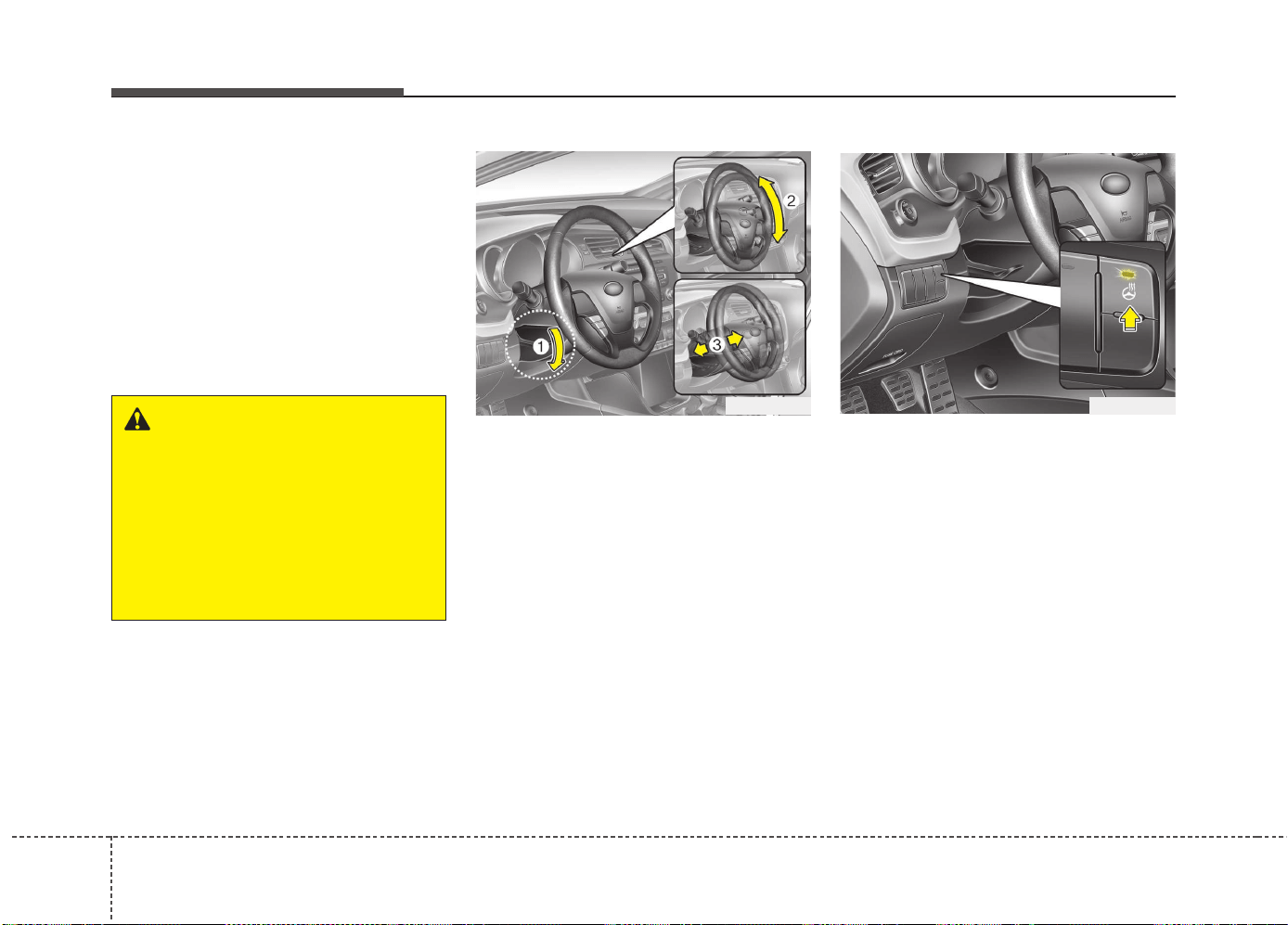
Features of your vehicle
404
Tilt and telescopic steering
A tilt and telescopic steering wheel
allows you to adjust the steering wheel
before you drive. You can also raise it to
give your legs more room when you exit
and enter the vehicle.
The steering wheel should be positioned
so that it is comfortable for you to drive,
while permitting you to see the instru-
ment panel warning lights and gauges.
To change the steering wheel angle, pull
down the lock release lever (1), adjust the
steering wheel to the desired angle (2)
and height (3), then pull up the lock-
release lever to lock the steering wheel in
place. Be sure to adjust the steering wheel
to the desired position before driving.
Heated steering wheel
(if equipped)
With the ignition switch in the ON posi-
tion, pressing the heated steering wheel
button warms the steering wheel.
✽✽
NOTICE
The heated steering wheel will turn off
automatically approximately 30 minutes
after the heated steering wheel is turned
on.
WARNING
• Never adjust the angle and height
of steering wheel while driving.
You may lose your steering con-
trol and cause severe personal
injury or accidents.
• After adjusting, push the steering
wheel both up and down to be
certain it is locked in position.
OJD042031 OJD042083
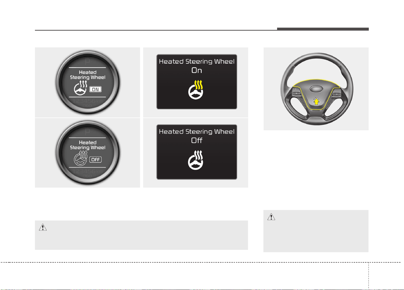
441
Features of your vehicle
Horn
To sound the horn, press the horn sym-
bol on your steering wheel.
Check the horn regularly to be sure it
operates properly.
✽✽
NOTICE
To sound the horn, press the area indi-
cated by the horn symbol on your steer-
ing wheel (see illustration). The horn will
operate only when this area is pressed.
OJD042032
CAUTION
Do not strike the horn severely to
operate it, or hit it with your fist. Do
not press on the horn with a sharp-
pointed object.
The indicator on the button will illuminate and notify you on the LCD display.
To turn the heated steering wheel off, press the button once again. The indicator on
the button will turn off and notify you on the LCD display.
CAUTION
Do not install any grip to operate the steering wheel. This causes damage to
the heated steering wheel system.
■ Normal vision
■ Supervision
OJD042165/OJD042166/OJD045189L/OJD045190L
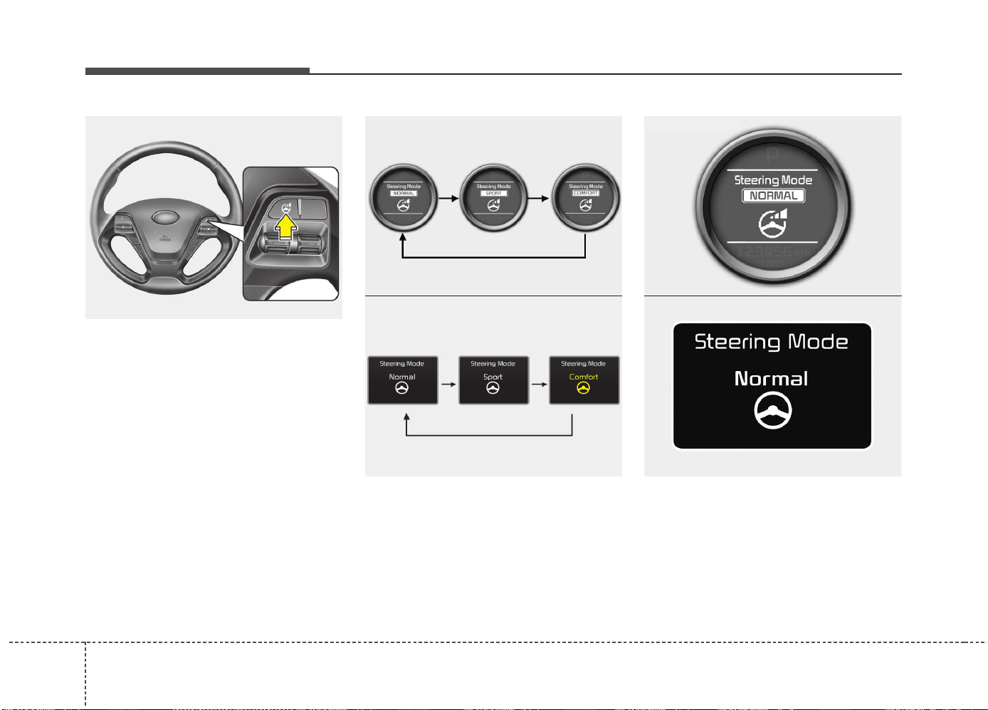
Features of your vehicle
424
Flex steering wheel (if equipped)
The flex steering wheel controls steering
effort as driver's preference or road con-
dition.
You can select the desired steering mode
by pressing the steering mode button.
When the steering mode button is
pressed, the selected steering mode will
appear on the LCD display.
If the steering mode button is pressed
within 4 seconds, the steering mode will
change as above pictures.
If the steering wheel mode button is not
pressed for about 4 seconds, the LCD dis-
play will change to the previous screen.
Normal mode
The normal mode offers medium steer-
ing effort.
OJD042161
OJD045541L
■ Normal vision
■ Supervision
OJD042167
OUM044267L
■ Normal vision
■ Supervision
OJD042170
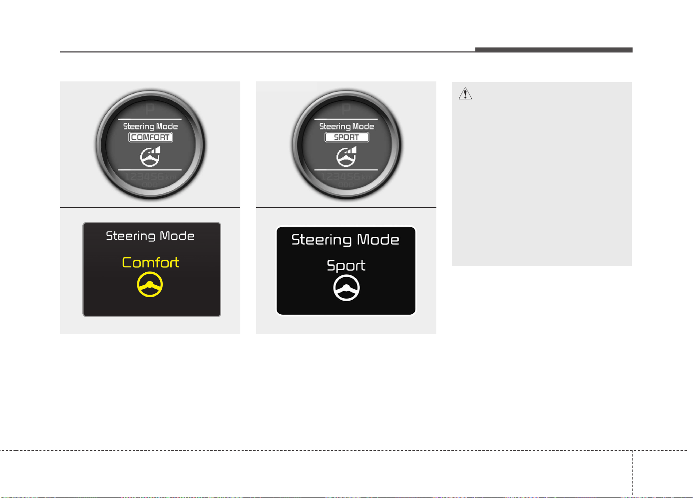
443
Features of your vehicle
Comfort mode
The steering wheel becomes lighter. The
comfort mode is usually used when driv-
ing in downtown or parking the vehicle.
Also, the comfort mode helps to drive
easily with lower effort to steer the car.
Sport mode
The steering wheel becomes heavier.
The sport mode is usually used when
driving in highway.
CAUTION
• For your safety, if you press the
steering mode button while oper-
ating the steering wheel, the LCD
display will change, but the steer-
ing effort will not change immedi-
ately. After operating the steering
wheel, the steering effort will
change automatically to the
selected mode.
• Be careful when changing the
steering mode while driving.
• When the electronic power steer-
ing is not working properly, the
flex steering wheel will not work.
OJD042169
OJD045521L
■ Normal vision
■ Supervision
OJD042168
OUM044268L
■ Normal vision
■ Supervision
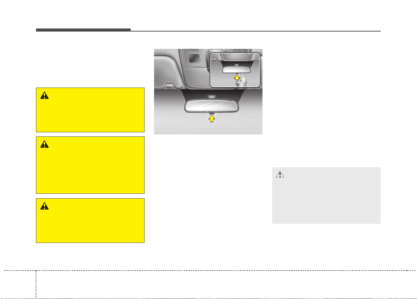
Features of your vehicle
444
Inside rearview mirror
Adjust the rearview mirror so that the
center view through the rear window is
seen. Make this adjustment before you
start driving.
Day/night rearview mirror
(if equipped)
Make this adjustment before you start
driving and while the day/night lever is in
the day position.
Pull the day/night lever toward you to
reduce glare from the headlights of vehi-
cles behind you during night driving.
Remember that you lose some rearview
clarity in the night position.
Electric chromic mirror (ECM)
(if equipped)
The electric rearview mirror automatical-
ly controls the glare from the headlights
of the car behind you in nighttime or low
light driving conditions. The sensor
mounted in the mirror senses the light
level around the vehicle, and automati-
cally controls the headlight glare from
vehicles behind you.
When the engine is running, the glare is
automatically controlled by the sensor
mounted in the rearview mirror.
Whenever the shift lever is shifted into R
(Reverse), the mirror will automatically go
to the brightest setting in order to improve
the drivers view behind the vehicle.
MIRRORS
WARNING - Rear visibility
Do not place objects in the rear
seat or cargo area which would
interfere with your vision out the
rear window.
CAUTION
When cleaning the mirror, use a
paper towel or similar material
dampened with glass cleaner. Do not
spray glass cleaner directly on the
mirror as that may cause the liquid
cleaner to enter the mirror housing.
WARNING
Do not adjust the rearview mirror
while the vehicle is moving. This
could result in loss of control, and
an accident which could cause
death, serious injury or property
damage.
WARNING
Do not modify the inside mirror and
do not install a wide mirror. It could
result in injury, during an accident
or deployment of the air bag.
OMD040031
DD
DD
aa
aa
yy
yy
NN
NN
ii
ii
gg
gg
hh
hh
tt
tt
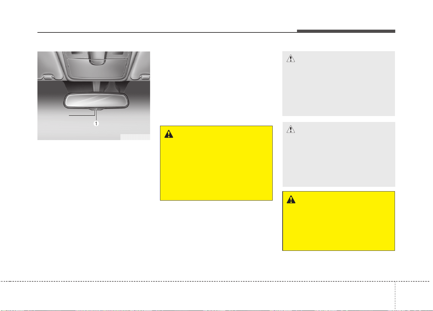
445
Features of your vehicle
To operate the electric rearview mirror:
• Press the on/off button (1) to turn the
automatic dimming function on. The
mirror indicator light will illuminate.
Press the on/off button to turn the auto-
matic dimming function off. The mirror
indicator light will turn off.
• The mirror defaults to the ON position
whenever the ignition switch is turned
on.
Outside rearview mirror
Be sure to adjust mirror angles before
driving.
Your vehicle is equipped with both left-
hand and right-hand outside rearview
mirrors. The mirrors can be adjusted
remotely with the remote switch. The mir-
ror heads can be folded back to prevent
damage during an automatic car wash or
when passing in a narrow street.
OMD040032
Indicator
WARNING - Rearview
mirrors
• The outside rearview mirror is
convex. Objects seen in the mir-
ror are closer than they appear.
• Use your interior rearview mirror
or direct observation to determine
the actual distance of following
vehicles when changing lanes.
CAUTION
Do not scrape ice off the mirror face;
this may damage the surface of the
glass. If ice should restrict move-
ment of the mirror, do not force the
mirror for adjustment.To remove ice,
use a deicer spray, or a sponge or
soft cloth with very warm water.
CAUTION
If the mirror is jammed with ice, do
not adjust the mirror by force. Use
an approved spray de-icer (not radi-
ator antifreeze) to release the
frozen mechanism or move the
vehicle to a warm place and allow
the ice to melt.
WARNING
Do not adjust or fold the outside
rearview mirrors while the vehicle
is moving. This could result in loss
of control, and an accident which
could cause death, serious injury
or property damage.
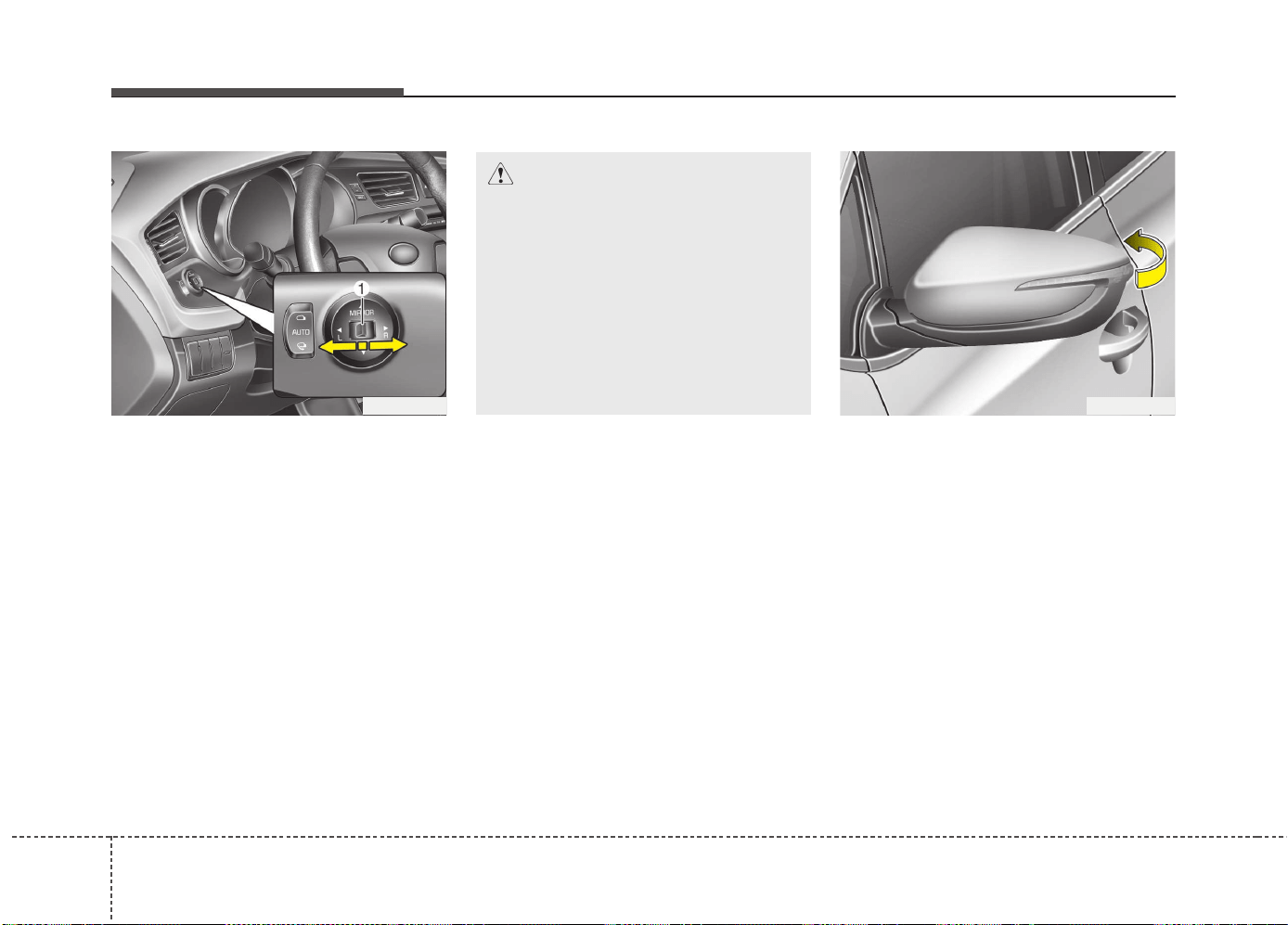
Features of your vehicle
464
Remote control
The electric remote control mirror switch
allows you to adjust the position of the
left and right outside rearview mirrors. To
adjust the position of either mirror, move
the lever (1) to R (Right) or L (Left) to
select the right side mirror or the left side
mirror, then press a corresponding point
on the mirror adjustment control to posi-
tion the selected mirror up, down, left or
right.
After adjustment, put the lever into neu-
tral (center) position to prevent inadver-
tent adjustment.
Folding the outside rearview mirror
Manual type
To fold outside rearview mirror, grasp the
housing of mirror and then fold it toward
the rear of the vehicle.
CAUTION
• The mirrors stop moving when
they reach the maximum adjust-
ing angles, but the motor contin-
ues to operate while the switch is
pressed. Do not press the switch
longer than necessary, the motor
may be damaged.
• Do not attempt to adjust the out-
side rearview mirror by hand.
Doing so may damage the parts.
OJD042033
OJD042034
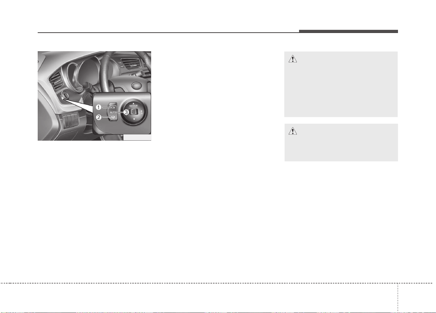
447
Features of your vehicle
Electric type
The outside rearview mirror can be fold-
ed or unfolded by pressing the switch as
below.
Up (1) : The mirror will unfold.
Down (2) : The mirror will fold.
Center (AUTO, 3) :
The mirror will fold or unfold automatical-
ly as follows:
• Without smart key system
- The mirror will fold or unfold when the
door is locked or unlocked by the
transmitter.
• With smart key system
- The mirror will fold or unfold when the
door is locked or unlocked by the
smart key.
- The mirror will fold or unfold when the
door is locked or unlocked by the but-
ton on the outside door handle.
- The mirror will unfold when you
approach the vehicle (all doors closed
and locked) with a smart key in pos-
session.
OJD042035
CAUTION
In case it is an electric type outside
rearview mirror, don’t fold it by
hand. It could cause motor failure.
CAUTION
The electric type outside rearview
mirror operates even though the
ignition switch is in the OFF posi-
tion. However, to prevent unneces-
sary battery discharge, do not adjust
the mirrors longer than necessary
while the engine is not running.
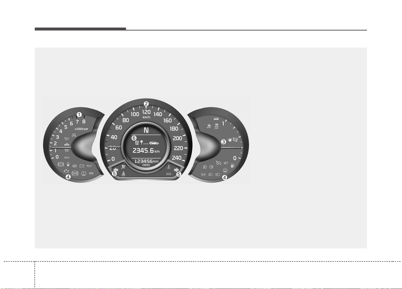
Features of your vehicle
484
INSTRUMENT CLUSTER (NORMAL VISION)
1. Tachometer
2. Speedometer
3. Fuel gauge
4. Warning and indicator lights (if equipped)
5. Turn signal indicators
6. LCD display
OJD042036
❈ The actual cluster in the vehicle may differ
from the illustration.
For more details, refer to "Gauges" in the
following pages.
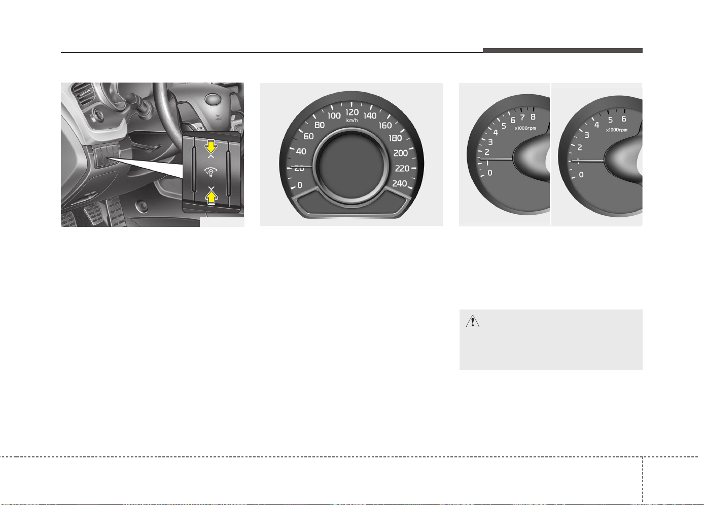
449
Features of your vehicle
Instrument panel illumination
The instrument panel illumination intensity
can be adjusted as follows:
• Ignition switch in the ON position
• Pressing the upper or lower part of the
switch
The illumination intensity is shown on the
instrument cluster LCD display.
Gauges
Speedometer
The speedometer indicates the vehicle
speed.
The speedometer is calibrated in kilome-
ters per hour and/or miles per hour.
Tachometer
The tachometer indicates the engine
speed in revolutions per minute (rpm).
Use the tachometer to select the correct
shift points and to prevent lugging and/or
over-revving the engine.
OJD042047
OJD042044/OJD042045
OJD042040
■ Diesel Engine■ Gasoline Engine
CAUTION
Do not operate the engine within
the tachometer's RED ZONE. This
may cause severe engine damage.
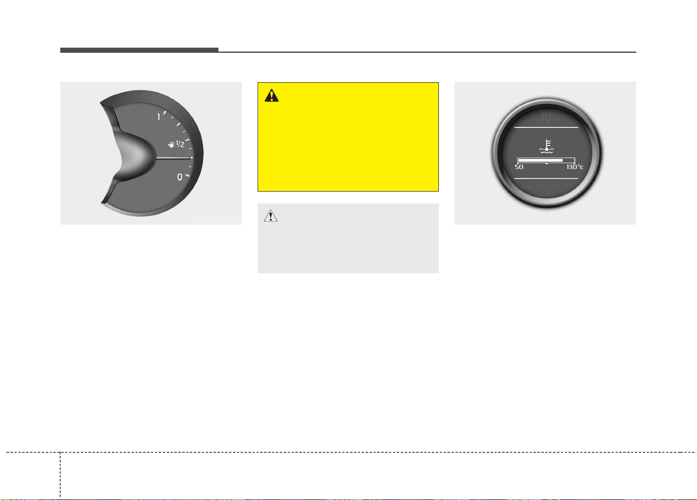
Features of your vehicle
504
Fuel gauge
The fuel gauge indicates the approxi-
mate amount of fuel remaining in the fuel
tank.
✽✽
NOTICE
• The fuel tank capacity is given in
chapter 8.
• The fuel gauge is supplemented by a
low fuel warning light, which will illu-
minate when the fuel tank is nearly
empty.
• On inclines or curves, the fuel gauge
may fluctuate or the low fuel warning
light may come on earlier than usual
due to the movement of fuel in the tank.
Engine coolant temperature gauge
This gauge shows the temperature of the
engine coolant when the ignition switch
is ON.
Do not continue driving with an overheat-
ed engine. If your vehicle overheats, refer
to “If the engine overheats” in chapter 6.
WARNING - Fuel gauge
Running out of fuel can expose
vehicle occupants to danger.
You must stop and obtain addition-
al fuel as soon as possible after the
warning light comes on or when the
gauge indicator comes close to the
“O (Empty)” level.
CAUTION
Avoid driving with an extremely low
fuel level. Running out of fuel could
cause the engine to misfire damag-
ing the catalytic converter.
OJD042046
OJD042058
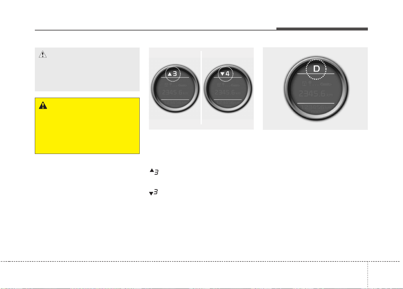
451
Features of your vehicle
Manual transaxle shift indicator
(if equipped)
This indicator informs you which gear is
desired while driving to save fuel.
For example
: Indicates that shifting up to the 3rd
gear is desired (currently the shift
lever is in the 2nd or 1st gear).
: Indicates that shifting down to the
3rd gear is desired (currently the
shift lever is in the 4th or 5th gear).
You can turn off the indicator. Refer to
“User setting” in this chapter.
Automatic transaxle shift position
indicator (if equipped)
The indicator displays which automatic
transaxle shift lever is selected.
OJD042233OJD042231/OJD042232
CAUTION
If the gauge pointer moves beyond
the normal range area toward the
“130°C”, it indicates overheating
that may damage the engine.
WARNING
Never remove the radiator cap
when the engine is hot. The engine
coolant is under pressure and
could cause severe burns. Wait
until the engine is cool before
adding coolant to the reservoir.
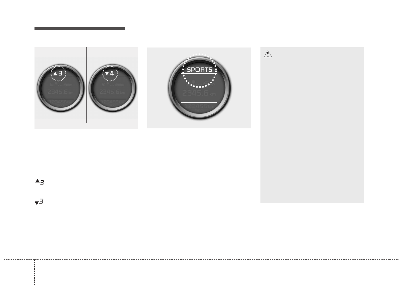
Features of your vehicle
524
Automatic Transaxle Shift Indicator in
sports mode (if equipped, For Europe)
In the Sports Mode, this indicator informs
which gear is desired while driving to
save fuel.
For example
: Indicates that shifting up to the 3rd
gear is desired (currently the shift
lever is in the 2nd or 1st gear).
: Indicates that shifting down to the 3rd
gear is desired (currently the shift
lever is in the 4th, 5th, or 6th gear).
When the system is not working properly,
the indicator is not displayed.
Dual clutch transmission
(DS mode) shift indicator
(if equipped)
The indicator displays which Dual clutch
transmission shift lever is selected.
In DS mode, the “SPORTS” indicator dis-
plays in cluster. For more detailed infor-
mation about DS mode, refer to the chap-
ter 5.
OJD042234
OJD042231/OJD042232
■ Type A
■ Type B
* DCT : Dual clutch transmission
CAUTION - DCT
• When the problem of gear system
occurs, the transaxle indicator
will blink. For your safety, we rec-
ommend that you contact an
authorized Kia dealer and have
the system checked.
• When the clutch is overheated,
the safe protection mode oper-
ates. According to the safe protec-
tion mode, the transaxle indicator
blinks with buzzer sound. The
buzzer beeps 3 times. In this time,
the LCD warning about safe pro-
tection mode also displays. In this
condition, the driving may not be
smoothly. If you ignore this warn-
ing, the driving condition is get-
ting worse and the system may
have problem. To return the nor-
mal driving condition, apply the
foot brake and stop the vehicle for
few minutes before driving off.
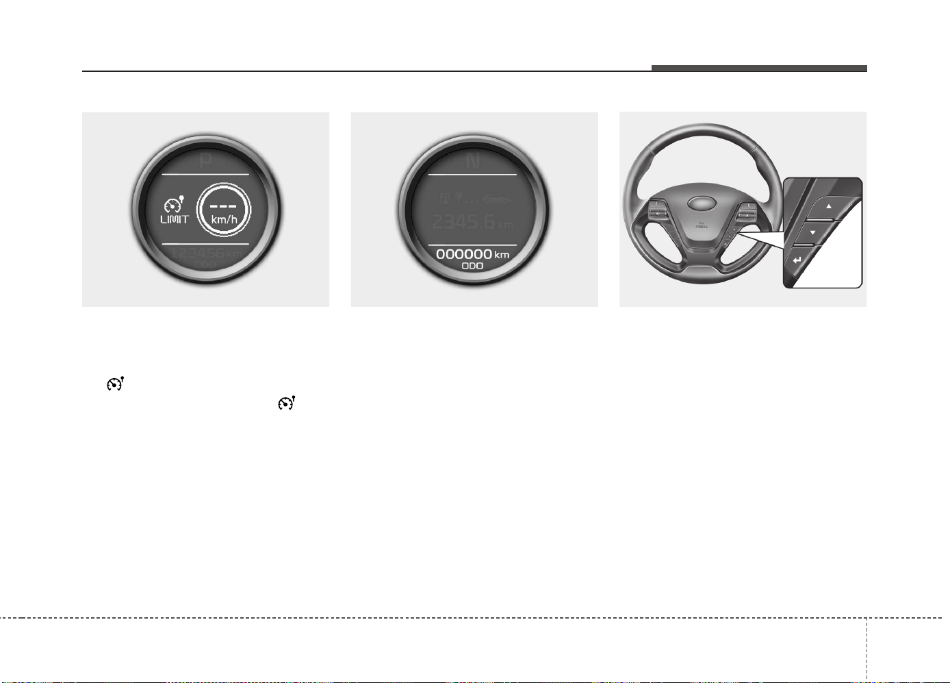
453
Features of your vehicle
Speed limiter indicator
(if equipped)
The indicator illuminates when the speed
limit control system is enabled by move
the lever up on the steering wheel.
The indicator goes off when the lever
up again to deactivate the system.
If there is a problem with the speed limit
control system, the “---” indicator will blink.
If this occurs, we recommend that the
system be checked by an authorized Kia
dealer.
For more details, refer to “Speed limit
control system” in chapter 5.
The speed limiter indicators illuminates
on the LCD display.
Odometer (km or mi.)
The odometer indicates the total dis-
tance the vehicle has been driven.
You will also find the odometer useful to
determine when periodic maintenance
should be performed.
Trip computer
The trip computer is a microcomputer-
controlled driver information system that
displays information related to driving
when the ignition switch is in the ON
position. All stored driving information
(except odometer, distance to empty and
instant fuel economy) resets if the battery
is disconnected.
OJD052031
OJD042051
OJD042050
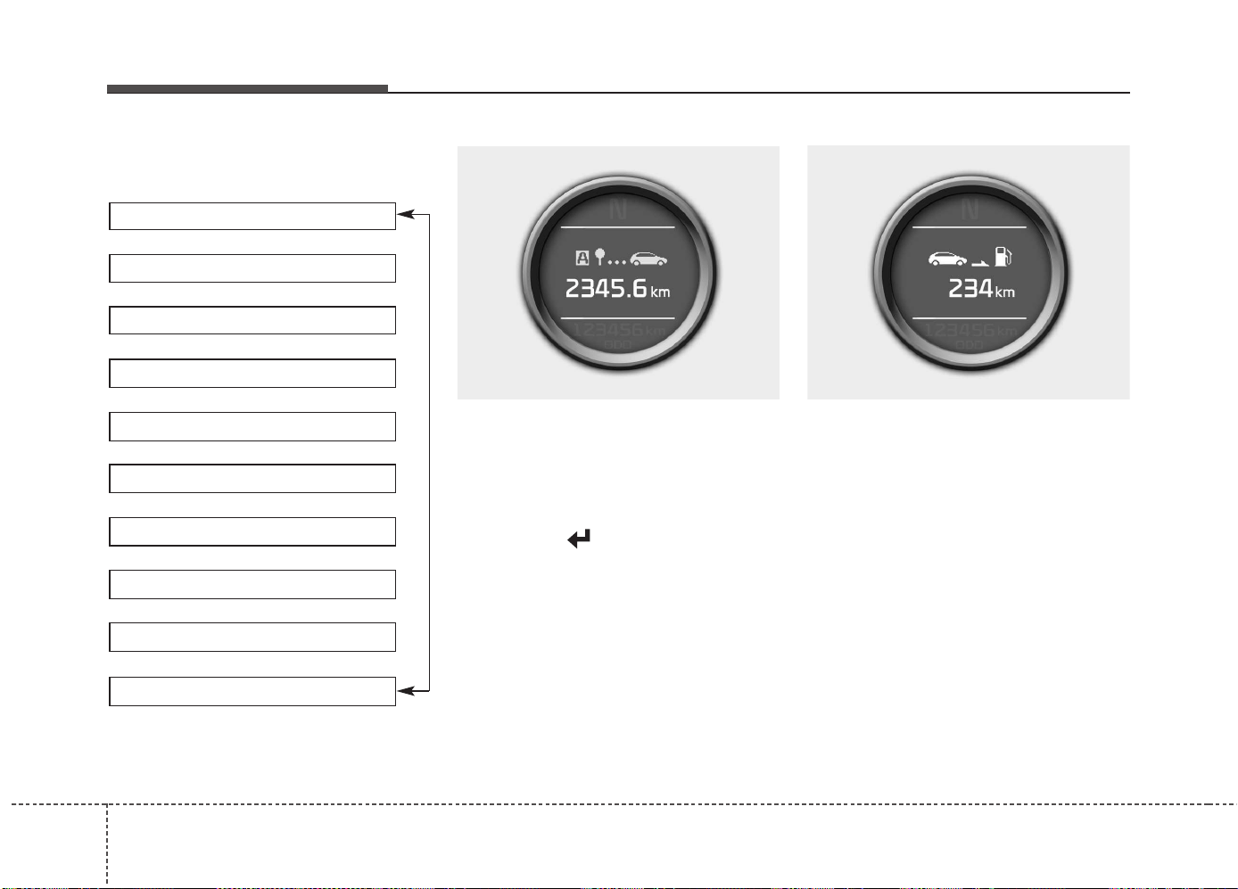
Features of your vehicle
544
Press the ▲ or ▼ button for less than 1
second to select any mode as follows:
Tripmeter (km or mi.)
This mode indicates the distance of indi-
vidual trips selected since the last trip-
meter reset.
The meter's working range is from 0.0 to
9999.9 km (0.0 to 9999.9 miles).
Pressing the button for more than 1
second, clears the tripmeter to zero (0.0).
Distance to empty (km or mi.)
This mode indicates the estimated dis-
tance the vehicle can be driven with the
remaining fuel. When the remaining dis-
tance is below 50 km (30 miles), “---” will
be displayed.
The meter’s working range is from 50 to
999 km (30 to 999 miles).
OJD042052
Tripmeter B
Instant fuel consumption*
Tripmeter A
Distance to empty*
Average fuel consumption*
Engine coolant temperature gauge
* : if equipped
Elapsed time*
Average speed*
↔↔↔↔
↔
↔↔↔↔↔↔↔↔↔↔↔
Service*
↔↔
User setting*
↔↔
OJD042053
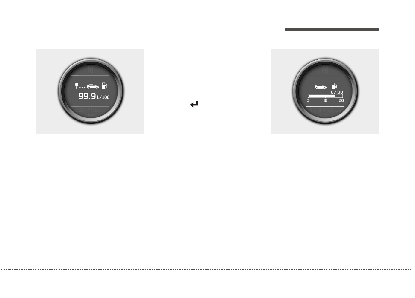
455
Features of your vehicle
Average fuel economy (if equipped)
(L/100 km or MPG)
This mode calculates the average fuel
consumption from the total fuel used and
the distance since the last average fuel
economy reset. The total fuel used is cal-
culated from the fuel consumption input.
For an accurate calculation, drive more
than 50 m (0.03 miles).
To clear the average fuel economy to
zero (--.-), do as follow;
• When the “AVG Fuel Economy” of
“User Setting” is in the “Auto Reset”
If the vehicle speed exceeds 1 km/h after
refueling more than 6 l, the average fuel
consumption will be cleared to zero (---).
• When the “AVG Fuel Economy” of
“User Setting” is in the “Manual Reset”
Pressing the button for more than 1
second, when the average fuel consump-
tion is displayed, clears the average fuel
consumption to zero (--.-).
Instant fuel economy (if equipped)
(L/100 km or MPG)
This mode calculates the instant fuel con-
sumption during the last few seconds.
OJD042054 OJD042055
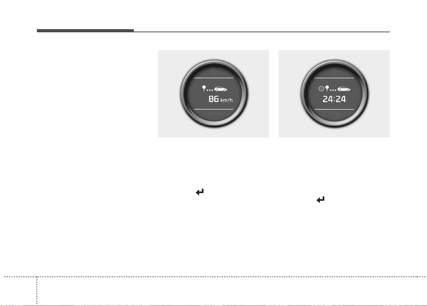
Features of your vehicle
564
✽✽
NOTICE
• If the vehicle is not on level ground or
the battery power has been interrupt-
ed, the “Distance to empty” function
may not operate correctly.
The trip computer may not register
additional fuel if less than 6 liters (1.6
gallons) of fuel are added to the vehicle.
• The fuel economy and distance to
empty may vary significantly based
on driving conditions, driving habits,
and condition of the vehicle.
• The distance to empty is an estimate
of the available driving distance. This
value may differ from the actual driv-
ing distance.
Average speed (km/h or MPH)
This mode calculates the average speed
of the vehicle since the last average
speed reset.
Even if the vehicle is not in motion, the
average speed keeps going while the
engine is running.
Pressing the button for more than 1
second, when the average speed is dis-
played, clears the average speed to zero
(---).
Elapsed time
This mode indicates the total time trav-
eled since the last driving time reset.
Even if the vehicle is not in motion, the
driving time keeps going while the engine
is running.
The meter’s working range is from
0:00~99:59.
Pressing the button for more than 1
second, when the driving time is being
displayed, clears the driving time to zero
(0:00).
OJD042056 OJD042057
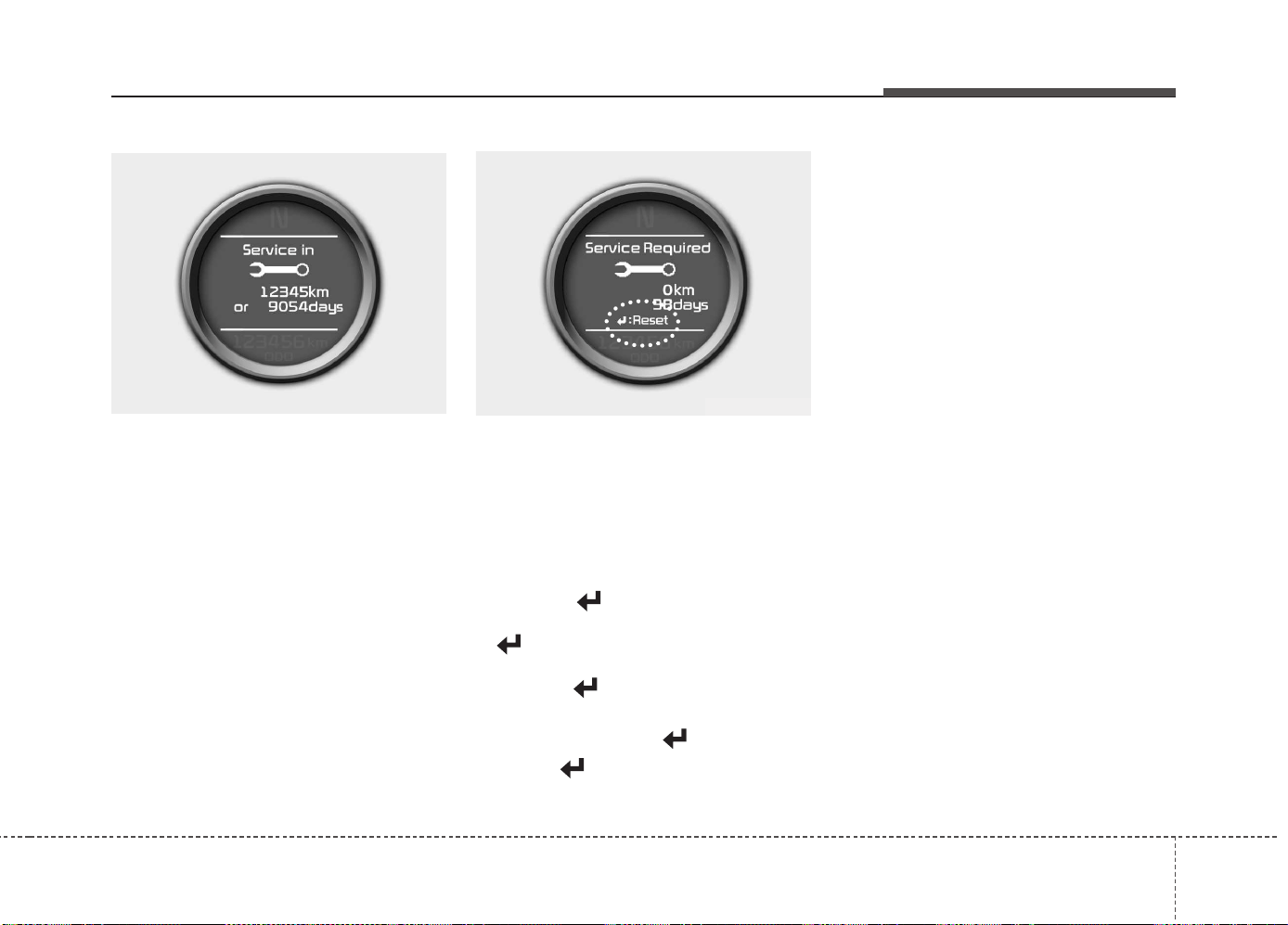
457
Features of your vehicle
Service mode
This mode calculates when you need a
scheduled maintenance service (mileage
or days)
If you want to see the service mode when
other modes are displayed, press the ▲
or ▼ button less than 1 second.
If you do not have your vehicle serviced
according to the scheduled maintenance
service on the LCD display, this LCD dis-
play will show the elapsed mileage or days.
If you want to reset the maintenance
schedule, when the service required mes-
sage is displayed :
- Press the button more than 5 sec-
onds.
- " : Reset" will be shown on the LCD
display.
- Press the button again more than 1
second.
If you do not press the button within 5
seconds, " : Reset" will disappear.
If you want to change the interval of the
maintenance service schedule, we rec-
ommend that you consult an authorized
Kia dealer.
✽✽
NOTICE
• If you reset the maintenance schedule,
when the displayed service schedule
has not elapsed or elapsed without
actual vehicle service, the displayed
service schedule on the LCD display
might not be match the actual service
schedule anymore.
You should comply with the displayed
service schedule on the LCD display
for the maintenance of your vehicle.
• If the battery is disconnected or dis-
charged, the displayed service sched-
ule might not match the actual service
schedule.
OJD042061
OJD042059
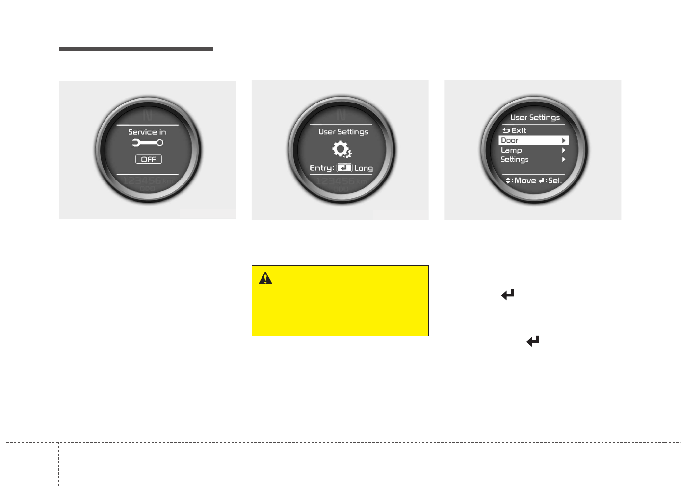
Features of your vehicle
584
If service mode is not activated, the LCD
display shows, like the above picture.
In this case, we recommend that you
consult an authorized Kia dealer.
User Settings
In this mode there are 3 kinds of the sub-
menu.
1. Stop the vehicle with the ignition
switch in the ON position or engine
running.
2. Press the ▲ or ▼ button until the User
setting mode is displayed.
3. With the User setting mode displayed,
press the button until the screen
is changed.
4. You can change the item by pressing
the ▲ or ▼ button and select an item
by pressing the button.
OJD042063
OJD042060
OJD042064
WARNING
Do not adjust the User Setting
while driving. You may lose your
steering control and cause severe
personal injury or accidents.

459
Features of your vehicle
Door Menu
• Auto Door Lock
Off - The auto door lock operation will be
canceled.
Speed - All doors will be automatically
locked when the vehicle speed
exceeds 15km/h (9.3mph).
Shift Lever - All doors will be automati-
cally locked if the shift lever
is shifted from the P(Park)
position to the R(Reverse),
N(Neutral) or D(Drive) posi-
tion. (for automatic transaxle
shift lever)
• Auto Door Unlock
Off - The auto door unlock operation will
be canceled.
Key Out - All doors will be automatically
unlocked when the ignition key
is removed from ignition switch
(or smart key is in the OFF
position).
Shift Lever - All doors will be automati-
cally unlocked if the shift
lever is shifted to the
P(Park) position. (for auto-
matic transaxle shift lever)
Lamp Menu
• Headlamp delay (if equipped)
If the headlamp delay function is checked :
The Headlamp delay and Headlamp
Welcome function will be activated.
• Welcome Light (if equipped)
If the welcome light function is checked :
The welcome light function of puddle
lamp will activate.
• Auto Triple Turn
(One-touch triple turn signal)
If the auto triple turn function is checked :
The lane change signals will blink 3 times
when the turn signal lever is moved
slightly.
Settings Menu
• Seat Easy Access (for Driver Position
Memory System equipped vehicle)
(if equipped)
If the seat easy access function is
checked :
The driver's seat will automatically move
forward or rearward for the driver to enter
or exit the vehicle comfortably.
• Steering position (if equipped)
If the steering position function is
checked:
The warning illuminates on the LCD dis-
play when the steering wheel is not
aligned with the ENGINE STRAT/STOP
button in the ON position.
• Shift indicator (for manual transaxle)
If the shift indicator function is checked :
The shift indicator function will be activated.
For more details, refer to “Manual
transaxle shift indicator” in this chapter.

Features of your vehicle
604
• AVG fuel ECO Reset
Auto Reset - The average fuel economy
will reset automatically
when you drive after refuel-
ing.
Manual Reset - The average fuel econo-
my will not reset auto-
matically when you drive
after refueling. You can
reset the average fuel
economy by pressing
the button for more
than 1 second when the
average fuel economy is
displayed.
• Language
Choose the language you prefer within
the LCD display.
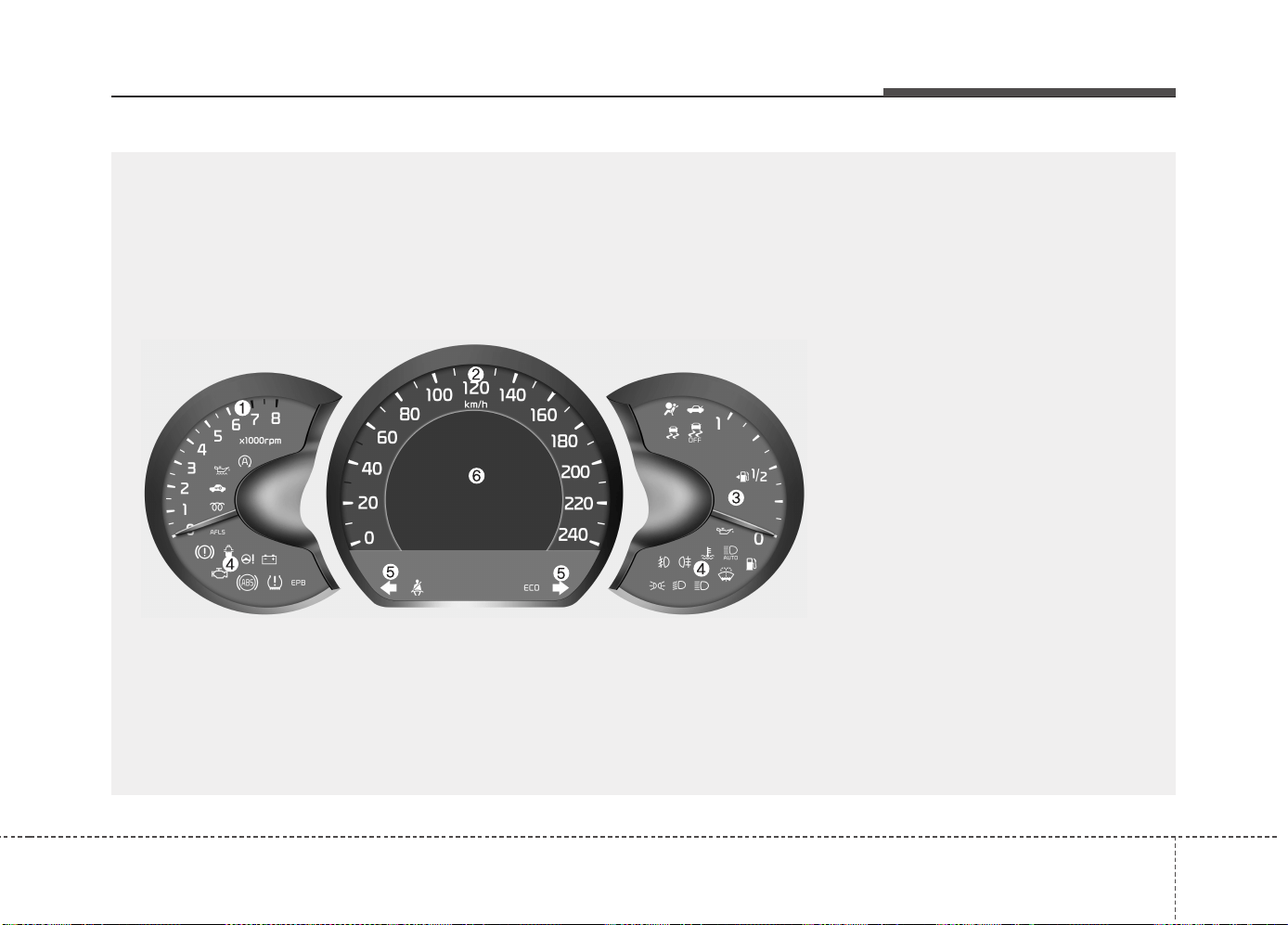
461
Features of your vehicle
INSTRUMENT CLUSTER (SUPERVISION)
1. Tachometer
2. Speedometer
3. Fuel gauge
4. Warning and indicator lights (if equipped)
5. Turn signal indicators
6. LCD display
❈ The actual cluster in the vehicle may differ
from the illustration.
For more details, refer to "Gauges" in the
following pages.
OJD045100
■ Type A
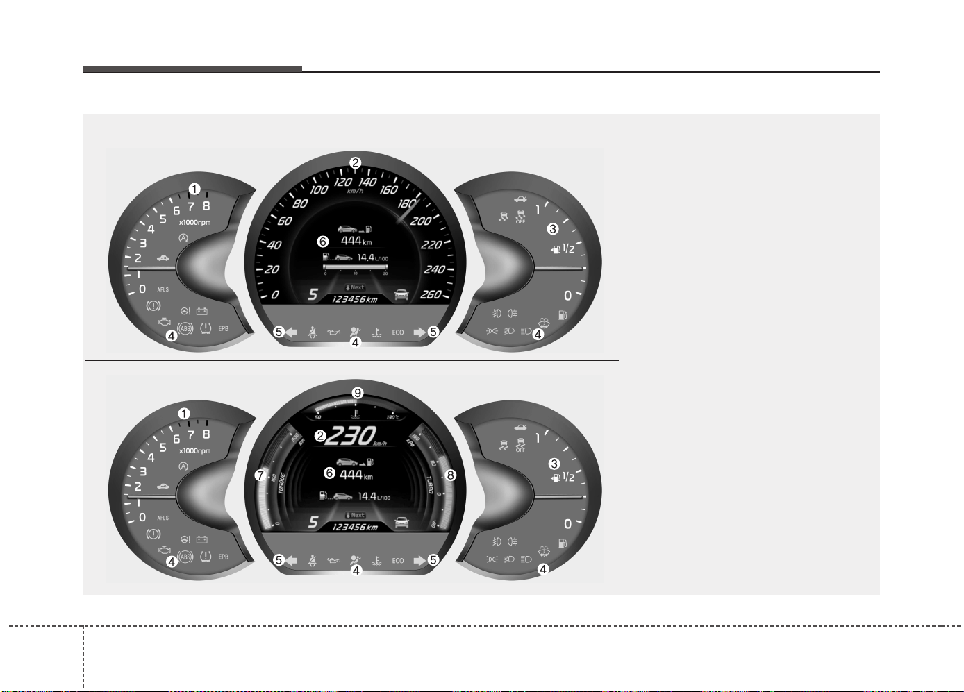
Features of your vehicle
624
1. Tachometer
2. Speedometer
3. Fuel gauge
4. Warning and indicator lights (if equipped)
5. Turn signal indicators
6. LCD display
7. Engine torque gauge
8. Turbo boost pressure gauge
9. Engine coolant temperature gauge
OJD043038/OJD043248
❈ The actual cluster in the vehicle may differ
from the illustration.
For more details, refer to "Gauges" in the
following pages.
■ Type B (for T-GDI engine)
• Analog Mode
• Digital Mode
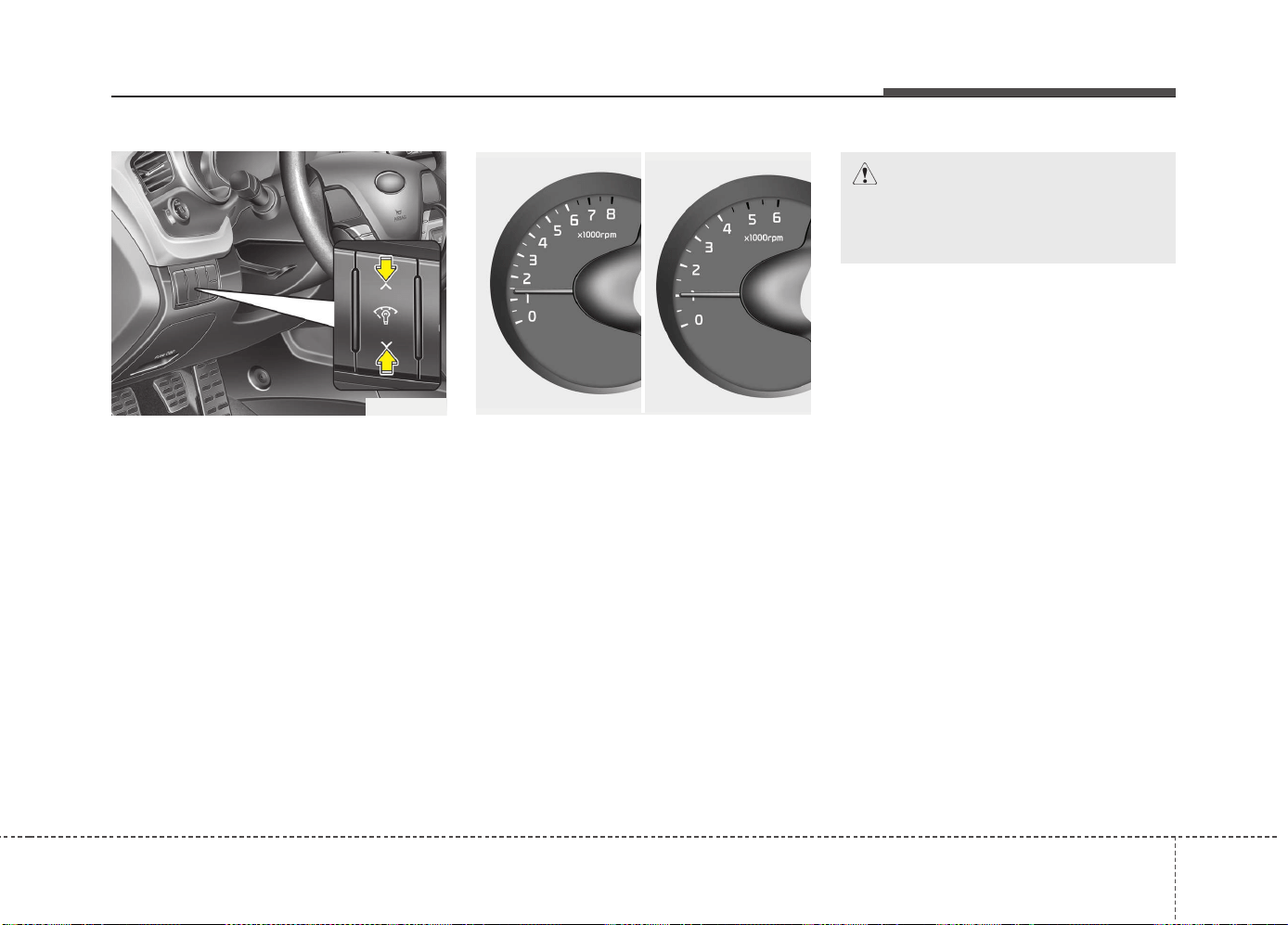
463
Features of your vehicle
Instrument panel illumination
The instrument panel illumination intensity
can be adjusted as follows:
• Ignition switch in the ON position
• Pressing the upper or lower part of the
switch
The illumination intensity is shown on the
instrument cluster LCD display.
Gauges
Tachometer
The tachometer indicates the engine
speed in revolutions per minute (rpm).
Use the tachometer to select the correct
shift points and to prevent lugging and/or
over-revving the engine.
OJD042047
CAUTION
Do not operate the engine within
the tachometer's RED ZONE. This
may cause severe engine damage.
OJD042044/OJD042045
■ Diesel Engine■ Gasoline Engine
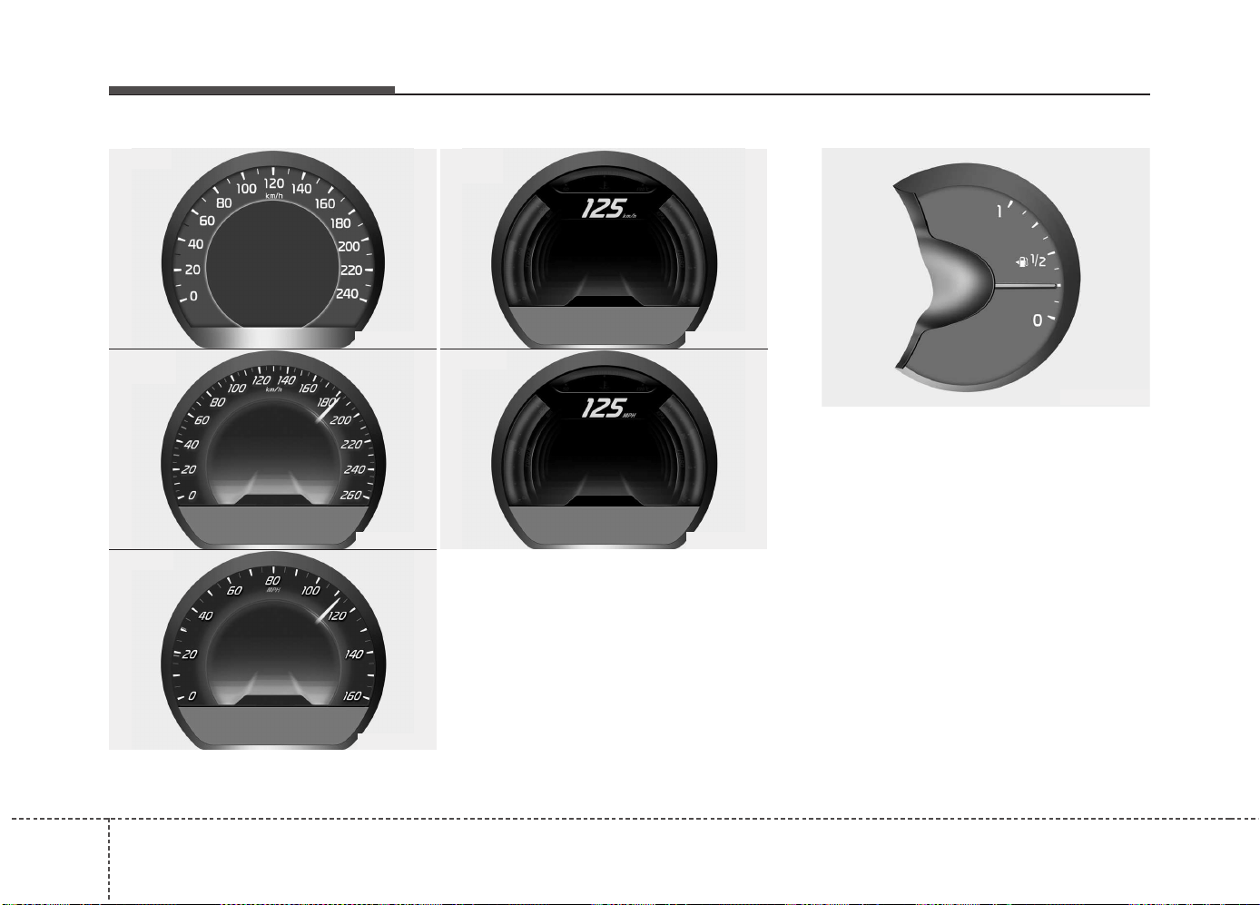
Features of your vehicle
644
Speedometer
The speedometer indicates the vehicle
speed.
The speedometer is calibrated in kilome-
ters per hour and/or miles per hour.
Fuel gauge
The fuel gauge indicates the approxi-
mate amount of fuel remaining in the fuel
tank.
✽✽
NOTICE
• The fuel tank capacity is given in
chapter 8.
• The fuel gauge is supplemented by a
low fuel warning light, which will illu-
minate when the fuel tank is nearly
empty.
• On inclines or curves, the fuel gauge
may fluctuate or the low fuel warning
light may come on earlier than usual
due to the movement of fuel in the tank.
OJD042046
OJD042042
OJD043505
OJD043506
■ Type B
• km/h
■ Type A
• MPH
OJD043507
OJD043508
• MPH
■ Type C
• km/h
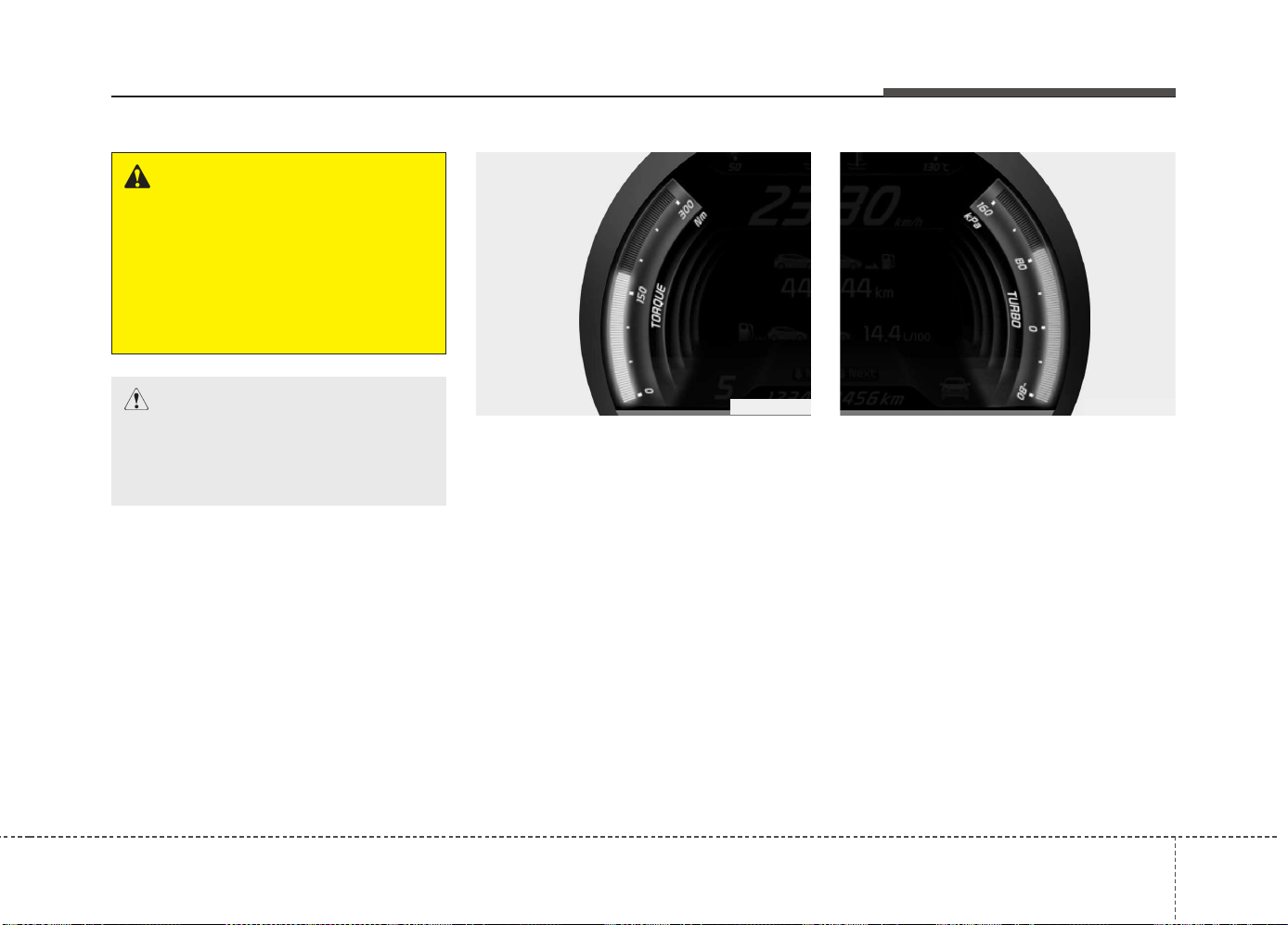
465
Features of your vehicle
Engine torque gauge
(for T-GDI engine)
It shows instantaneous change of the
Torque by rpm.
Turbo boost pressure gauge
(for T-GDI engine)
It shows instantaneous change of the
turbo boost pressure.
WARNING - Fuel gauge
Running out of fuel can expose
vehicle occupants to danger.
You must stop and obtain addition-
al fuel as soon as possible after the
warning light comes on or when the
gauge indicator comes close to the
“O (Empty)” level.
CAUTION
Avoid driving with an extremely low
fuel level. Running out of fuel could
cause the engine to misfire damag-
ing the catalytic converter.
OJD043249
OJD043251
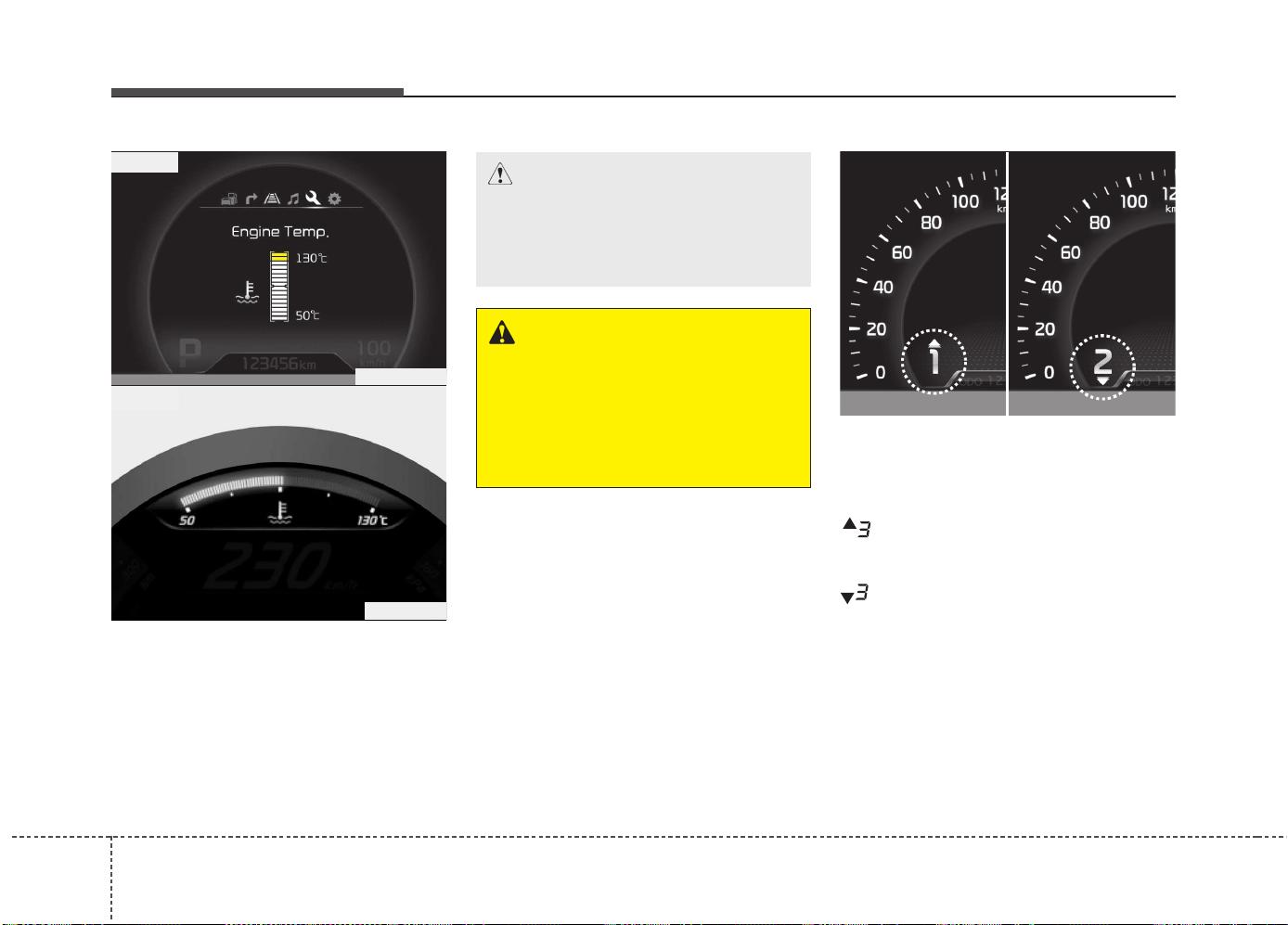
Features of your vehicle
664
Engine coolant temperature gauge
This gauge shows the temperature of the
engine coolant when the ignition switch
is ON.
Do not continue driving with an overheat-
ed engine. If your vehicle overheats, refer
to “If the engine overheats” in chapter 6.
Manual transaxle shift indicator
This indicator informs you which gear is
desired while driving to save fuel.
For example
: Indicates that shifting up to the 3rd
gear is desired (currently the shift
lever is in the 2nd or 1st gear).
: Indicates that shifting down to the
3rd gear is desired (currently the
shift lever is in the 4th or 5th gear).
OJD042236/OJD042237
CAUTION
If the gauge pointer moves beyond
the normal range area toward the
“130°C” position, it indicates over-
heating that may damage the engine.
WARNING
Never remove the radiator cap
when the engine is hot. The engine
coolant is under pressure and
could cause severe burns. Wait
until the engine is cool before
adding coolant to the reservoir.
OJD043250
■ Type B
■ Type A
OJD045176L
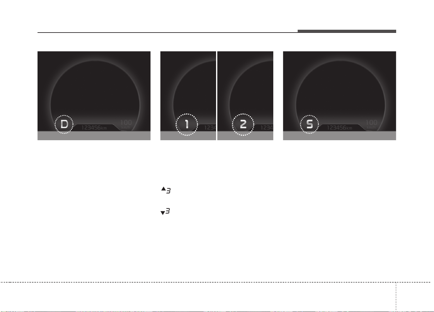
467
Features of your vehicle
Automatic transaxle shift position
indicator (if equipped)
The indicator displays which automatic
transaxle shift lever is selected.
Automatic Transaxle Shift Indicator in
sports mode (if equipped, For Europe)
In the Sports Mode, this indicator informs
which gear is desired while driving to
save fuel.
For example
: Indicates that shifting up to the 3rd
gear is desired (currently the shift
lever is in the 2nd or 1st gear).
: Indicates that shifting down to the 3rd
gear is desired (currently the shift
lever is in the 4th, 5th, or 6th gear).
When the system is not working properly,
the indicator is not displayed.
Dual clutch transmission
(DS mode) shift indicator
(if equipped)
The indicator displays which Dual clutch
transmission shift lever is selected.
In DS mode, the “S” indicator displays
with “SPORTS” indicator in cluster. For
more detailed information about DS
mode, refer to the chapter 5.
OJD045235 OJD045236/OJD045237 OJD045238
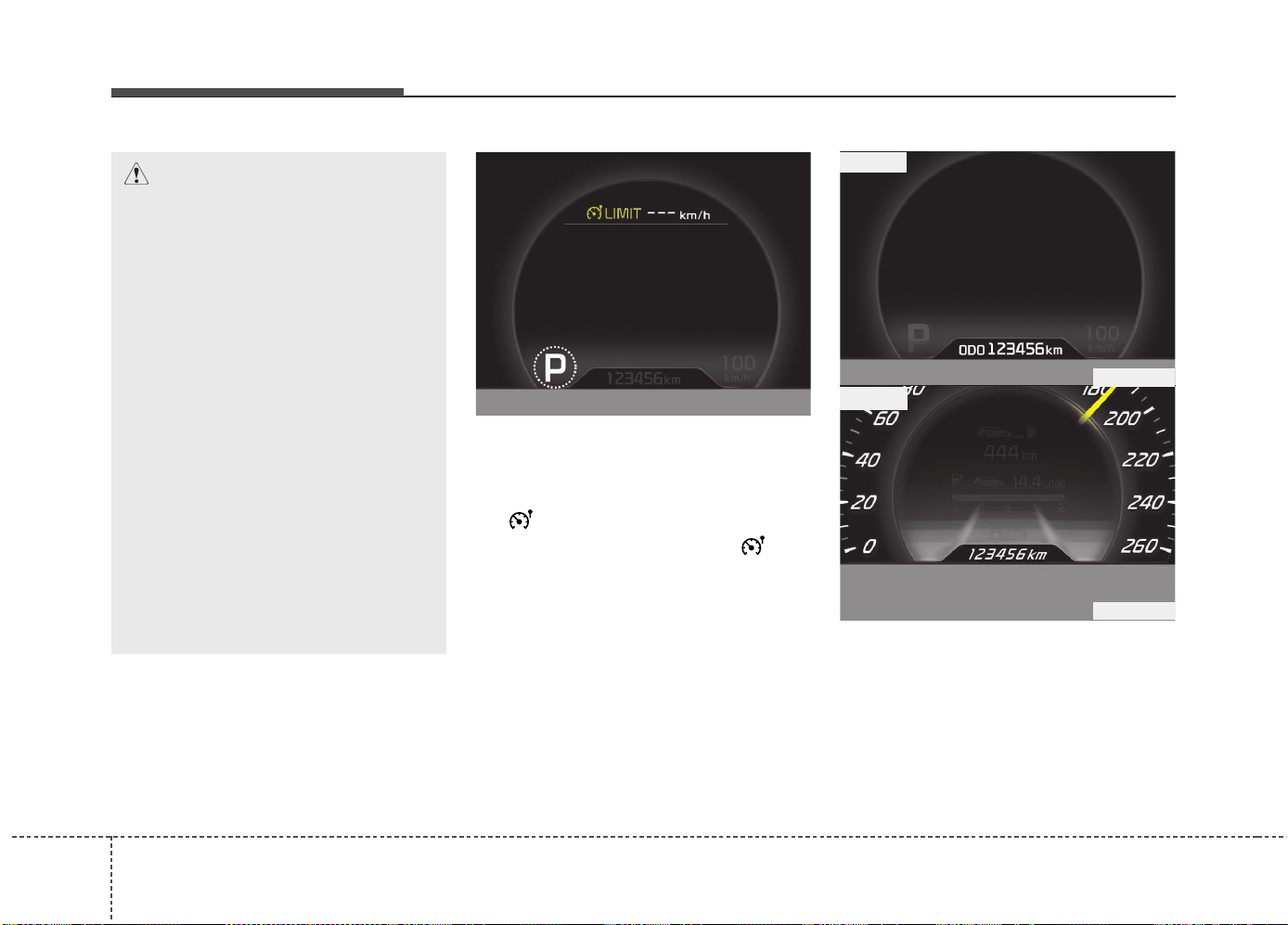
Features of your vehicle
684
Speed limiter indicator
(if equipped)
The indicator illuminates when the speed
limit control system is enabled by move
the lever up on the steering wheel.
The indicator goes off when the lever
up again to deactivate the system.
If there is a problem with the speed limit
control system, the “---” indicator will blink.
If this occurs, we recommend that the
system be checked by an authorized Kia
dealer.
For more details, refer to “Speed limit
control system” in chapter 5.
The speed limiter indicators illuminates
on the LCD display.
Odometer (km or mi.)
The odometer indicates the total dis-
tance the vehicle has been driven.
You will also find the odometer useful to
determine when periodic maintenance
should be performed.
CAUTION - DCT
• When the problem of gear system
occurs, the transaxle indicator
will blink. For your safety, we rec-
ommend that you contact an
authorized Kia dealer and have
the system checked.
• When the clutch is overheated,
the safe protection mode oper-
ates. According to the safe protec-
tion mode, the transaxle indicator
blinks with buzzer sound. The
buzzer beeps 3 times. In this time,
the LCD warning about safe pro-
tection mode also displays. In this
condition, the driving may not be
smoothly. If you ignore this warn-
ing, the driving condition is get-
ting worse and the system may
have problem. To return the nor-
mal driving condition, apply the
foot brake and stop the vehicle for
few minutes before driving off.
❈ DCT : Dual clutch transmission
OJD056043
OJD043504
■ Type B
■ Type A
OJD045173
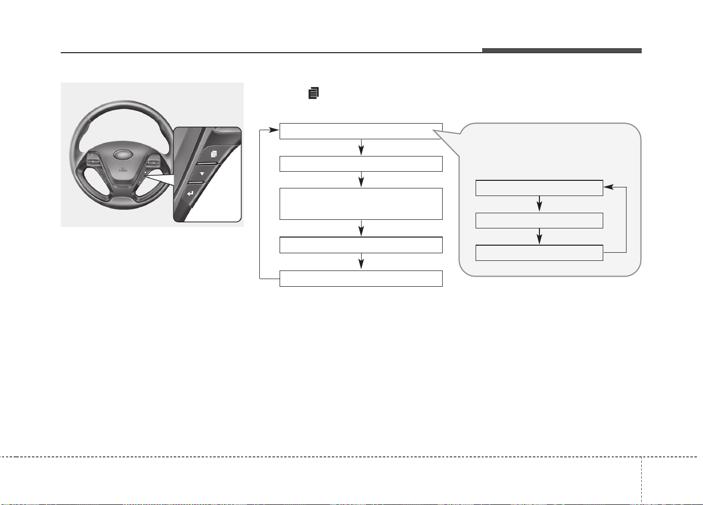
469
Features of your vehicle
Trip computer
The trip computer is a microcomputer-
controlled driver information system that
displays information related to driving
when the ignition switch is in the ON
position.
Press the button for less than 1 sec-
ond to select any group as follows :
OJD042172
Engine coolant temperature gauge*
User setting mode
Service mode
LANE DEPARTURE WARNING
SYSTEM*
Trip mode
* : if equipped
Trip mode A
Trip mode B
Driving information mode
Press the
▼
button for less than 1
second to select in Trip mode group
as follows :
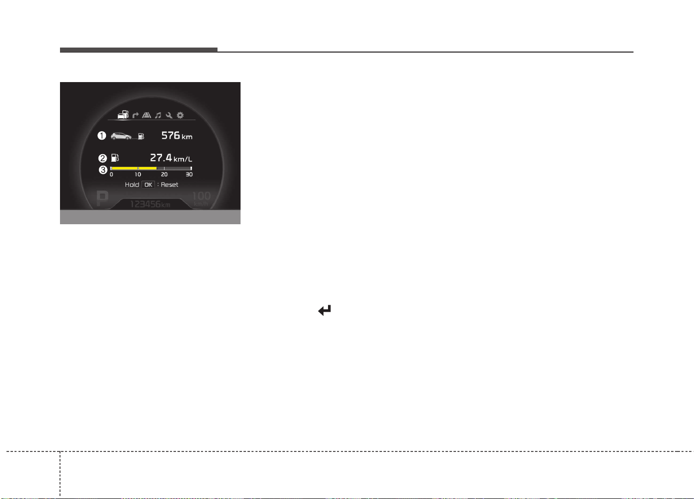
Features of your vehicle
704
Driving information mode
This mode indicates 3 kinds of driving
Information.
All stored driving information (except
odometer, distance to empty and instant
fuel economy) resets if the battery is dis-
connected.
1. Distance to empty (km or mi.)
This mode indicates the estimated dis-
tance the vehicle can be driven with the
remaining fuel. When the remaining dis-
tance is below 50 km (30 miles), “---” will
be displayed.
The meter’s working range is from 50 to
999 km (30 to 999 miles).
2. Average fuel economy
(L/100 km or MPG)
This mode calculates the average fuel
consumption from the total fuel used and
the distance since the last average fuel
economy reset. The total fuel used is cal-
culated from the fuel consumption input.
For an accurate calculation, drive more
than 50 m (0.03 miles).
To clear the average fuel economy to
zero (--.-), do as follow;
• When the “AVG Fuel Economy” of
“User Setting” is in the “Auto Reset”
If the vehicle speed exceeds 1 km/h after
refueling more than 6 l, the average fuel
consumption will be cleared to zero (---).
• When the “AVG Fuel Economy” of
“User Setting” is in the “Manual Reset”
Pressing the button for more than 1
second, when the average fuel consump-
tion is displayed, clears the average fuel
consumption to zero (--.-).
3. Instant fuel economy
(L/100 km or MPG)
This mode calculates the instant fuel
consumption during the last few sec-
onds.
✽✽
NOTICE
• If the vehicle is not on level ground or
the battery power has been interrupt-
ed, the “Distance to empty” function
may not operate correctly.
The trip computer may not register
additional fuel if less than 6 liters (1.6
gallons) of fuel are added to the vehicle.
• The fuel economy and distance to
empty may vary significantly based
on driving conditions, driving habits,
and condition of the vehicle.
• The distance to empty is an estimate
of the available driving distance. This
value may differ from the actual driv-
ing distance.
OJD045175
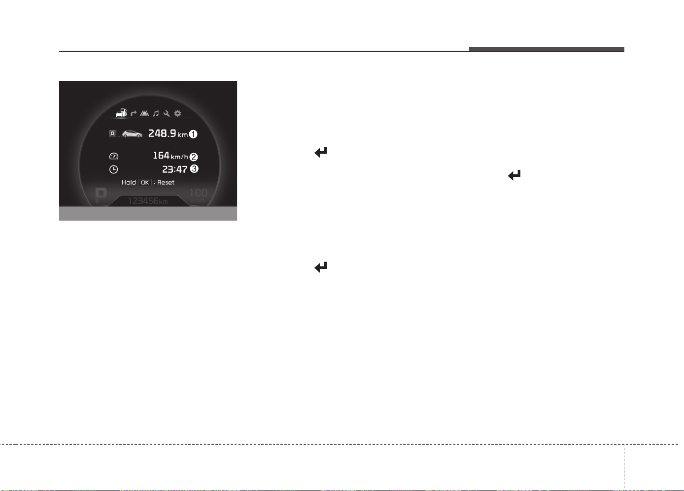
471
Features of your vehicle
Trip mode (A, B)
This mode indicates 3 kinds of driving
Information.
All stored driving information (except
odometer, distance to empty and instant
fuel economy) resets if the battery is dis-
connected.
1. Tripmeter (km or mi.)
This mode indicates the distance of indi-
vidual trips selected since the last trip-
meter reset.
The meter's working range is from 0.0 to
9999.9 km (0.0 to 9999.9 miles).
Pressing the button for more than 1
second, clears the tripmeter to zero (0.0).
2. Average speed (km/h or MPH)
This mode calculates the average speed
of the vehicle since the last average
speed reset.
Even if the vehicle is not in motion, the
average speed keeps going while the
engine is running.
Pressing the button for more than 1
second, when the average speed is dis-
played, clears the average speed to zero
(---).
3. Elapsed time
This mode indicates the total time trav-
eled since the last driving time reset.
Even if the vehicle is not in motion, the
driving time keeps going while the engine
is running.
The meter’s working range is from
0:00~99:59.
Pressing the button for more than 1
second, when the driving time is being
displayed, clears the driving time to zero
(0:00).
OJD045174
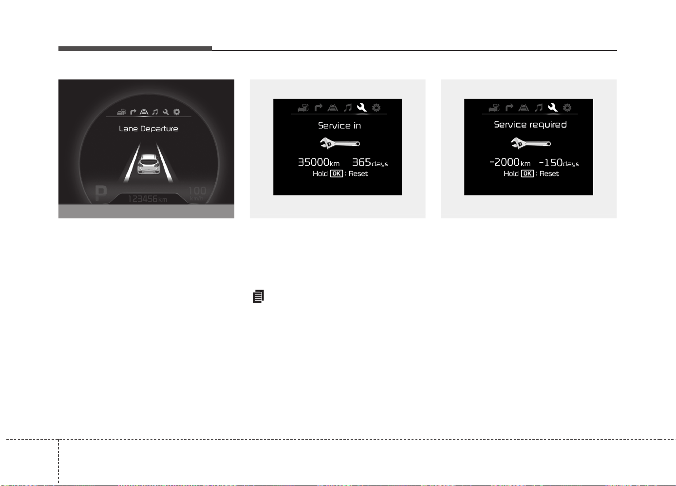
Features of your vehicle
724
Lane Departure Warning System
(LDWS) Mode (if equipped)
This mode displays the state of the Lane
Departure Warning System (LDWS).
For more details, refer to “Lane departure
warning system” in chapter 5.
Service mode
This mode calculates when you need a
scheduled maintenance service (mileage
or days)
If you want to see the service mode when
other modes are displayed, press the
button less than 1 second.
If you do not have your vehicle serviced
according to the scheduled maintenance
service on the LCD display, this LCD dis-
play will show the elapsed mileage or days.
OJD045180L OUM044258L OUM044259L
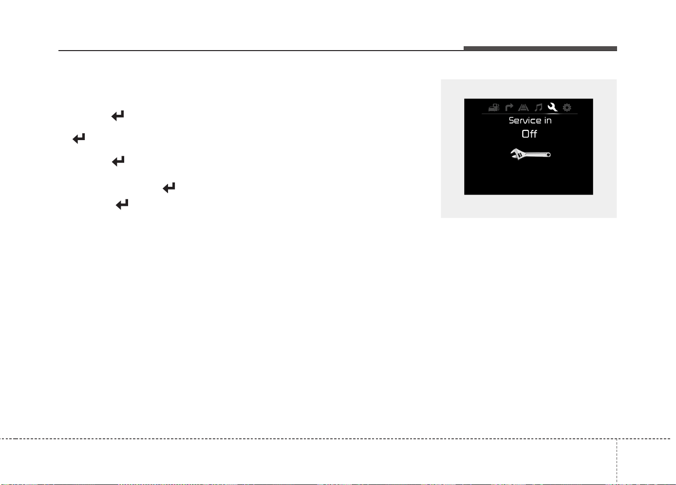
473
Features of your vehicle
If you want to reset the maintenance
schedule, when the service required mes-
sage is displayed :
- Press the button more than 5 sec-
onds.
- " : Reset" will be shown on the LCD
display.
- Press the button again more than 1
second.
If you do not press the button within
5 seconds, " : Reset" will disappear.
If you want to change the interval of the
maintenance service schedule, we rec-
ommend that you consult an authorized
Kia dealer.
✽✽
NOTICE
• If you reset the maintenance schedule,
when the displayed service schedule
has not elapsed or elapsed without
actual vehicle service, the displayed
service schedule on the LCD display
might not be match the actual service
schedule anymore.
You should comply with the displayed
service schedule on the LCD display
for the maintenance of your vehicle.
• If the battery is disconnected or dis-
charged, the displayed service sched-
ule might not match the actual service
schedule.
If service mode is not activated, the LCD
display shows, like the above picture.
In this case, we recommend that you
consult an authorized Kia dealer.
OUM044260L
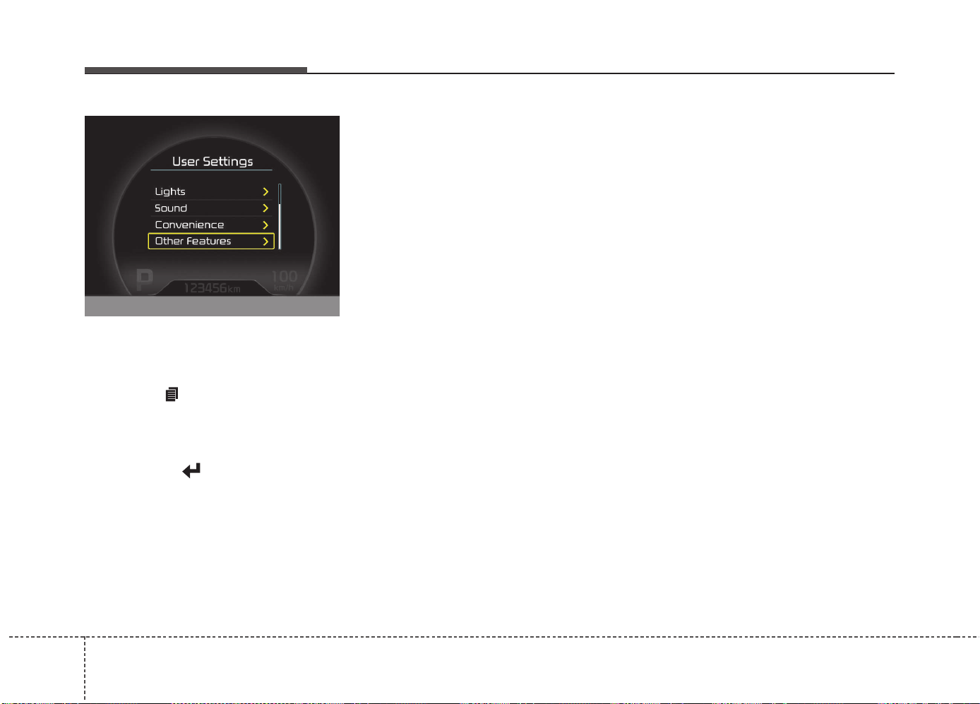
Features of your vehicle
744
User Settings
1. Stop the vehicle with the ignition
switch in the ON position or engine
running.
2. Press the button until the User set-
ting mode is displayed.
3. You can change the item by pressing
the
▼
button and select an item by
pressing the button.
Door Menu
• Auto Door Lock
Off - The auto door lock operation will be
canceled.
Speed - All doors will be automatically
locked when the vehicle speed
exceeds 15km/h (9.3mph).
Shift Lever - All doors will be automati-
cally locked if the shift lever
is shifted from the P(Park)
position to the R(Reverse),
N(Neutral) or D(Drive) posi-
tion. (for automatic transaxle
shift lever)
• Auto Door Unlock
Off - The auto door unlock operation will
be canceled.
Key Out - All doors will be automatically
unlocked when the ignition key
is removed from ignition switch
(or smart key is in the OFF
position).
Shift Lever - All doors will be automati-
cally unlocked if the shift
lever is shifted to the
P(Park) position. (for auto-
matic transaxle shift lever)
Lamp Menu
• Headlamp delay (if equipped)
If the headlamp delay function is checked :
The Headlamp delay and Headlamp
Welcome function will be activated.
• Auto Triple Turn
(One-touch triple turn signal)
If the auto triple turn function is checked :
The lane change signals will blink 3 times
when the turn signal lever is moved
slightly.
• Welcome Light (if equipped)
If the welcome light function is checked :
The welcome light function of puddle
lamp will activate.
OJD045522L

475
Features of your vehicle
Settings Menu
• Seat Easy Access (for Driver Position
Memory System equipped vehicle)
(if equipped)
If the seat easy access function is
checked:
The driver's seat will automatically move
forward or rearward for the driver to enter
or exit the vehicle comfortably.
• Welcome Sound
If the welcome sound function is checked :
The Welcome Sound function will be acti-
vated.
• Steering Position (if equipped)
If the steering position function is
checked:
The warning illuminates on the LCD dis-
play when the steering wheel is not
aligned with the ENGINE STRAT/STOP
button in the ON position.
• AVG fuel ECO Reset
Auto Reset - The average fuel economy
will reset automatically when
you drive after refueling.
Manual Reset - The average fuel econo-
my will not reset auto-
matically when you drive
after refueling. You can
reset the average fuel
economy by pressing
the button for more
than 1 second when the
average fuel economy is
displayed.
• Speed Gauge Scale (if equipped)
- 100% : The size of the numbers on
speed gauge is normal state.
- 110% : The size of the numbers on
speed gauge will increase.
• Unit
You can choose the displayed unit in the
instrument cluster “km” or “mile”.
• Language
Choose the language you prefer within
the LCD display.
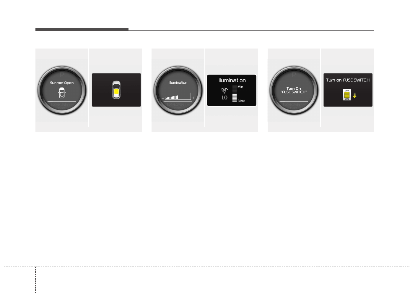
Features of your vehicle
764
LCD display information
Sunroof open
If driver removes the ignition key (Smart
key : turns off the engine) and opens the
driver-side door when the sunroof is not
fully closed, warning message will appear
on the LCD display. Also, the warning
chime sounds for approximately 7 sec-
onds.
Illumination intensity
The illumination intensity of the instru-
ment panel is shown when adjusting it
with the illumination control switch.
For more details, refer to “Instrument
panel illumination” in chapter 4.
Turn on "FUSE SWITCH" (mode switch)
The notice appears to inform the driver to
turn on the fuse switch in the instrument
panel under the steering wheel.
For more details, refer to “Fuses” in chap-
ter 7.
■ Normal vision
■ Supervision
■ Normal vision
■ Supervision
■ Normal vision
■ Supervision
OJD042240/OUM044265L OJD042079/OJD045523LOJD042078/OJD045215
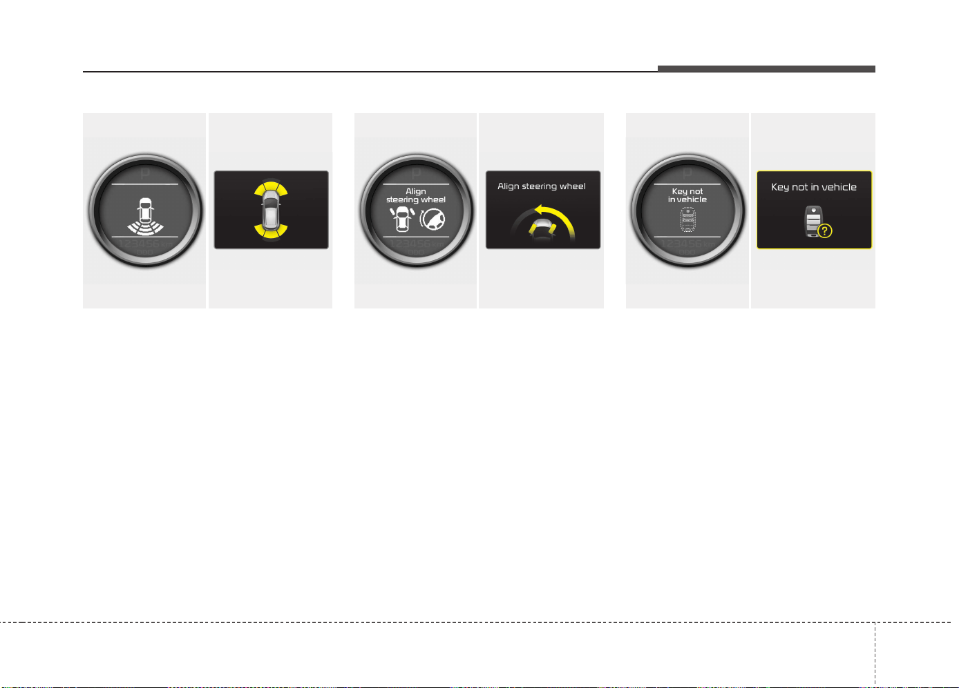
477
Features of your vehicle
Parking assist warning (if equipped)
Displays the area an obstacle is detected
while moving forward or rearward.
For more details, refer to “Parking assist
system” in chapter 4.
Align steering wheel (if equipped)
If you start the engine when the steering
wheel is turned 90 degrees to the left (or
right) after a couple of seconds, “Align
steering wheel” illuminates on the LCD
display for 5 seconds.
Turn the steering wheel to the right (or left)
and make it turned to the left (or right) less
than 30 degrees.
For vehicle’s equipped with smart
key system
Key not in vehicle
If the smart key is not in the vehicle and
if any door is opened or closed with the
engine start/stop button in the ACC, ON,
or START position, the warning illumi-
nates on the LCD display. Also, the chime
sounds for 5 seconds when the smart
key is not in the vehicle and the door is
closed.
Always have the smart key with you.
OJD042163/OJD045524
■ Normal vision
■ Supervision
OJD042164/OJD045525L
■ Normal vision
■ Supervision
OJD042073/OJD045526L
■ Normal vision
■ Supervision
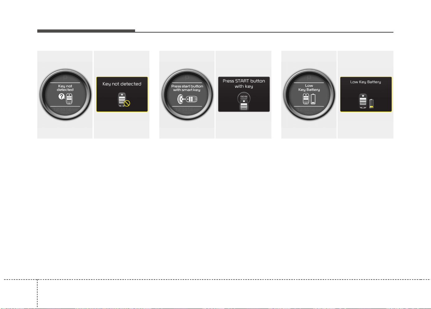
Features of your vehicle
784
Key not detected
If the smart key is not in the vehicle or is
not detected and you press the engine
start/stop button, the warning illuminates
on the LCD display for 10 seconds. Also,
the immobilizer indicator blinks for 10
seconds.
Press start button with smart key
If you press the engine start/stop button
while the warning “Key not detected” illu-
minates the warning “Press the start but-
ton with smart key” illuminates for 10 sec-
onds on the LCD display. Also, the immo-
bilizer indicator blinks for 10 seconds.
Low key battery
If the engine start/stop button changes to
the OFF position when the smart key in
the vehicle discharges, the warning illu-
minates on the LCD display for about 10
seconds. Also, the warning chime
sounds once.
Replace the battery with a new one.
OJD042072/OJD045527L
■ Normal vision
■ Supervision
OJD042075/OJD045528L
■ Normal vision
■ Supervision
OJD042066/OJD045529L
■ Normal vision
■ Supervision
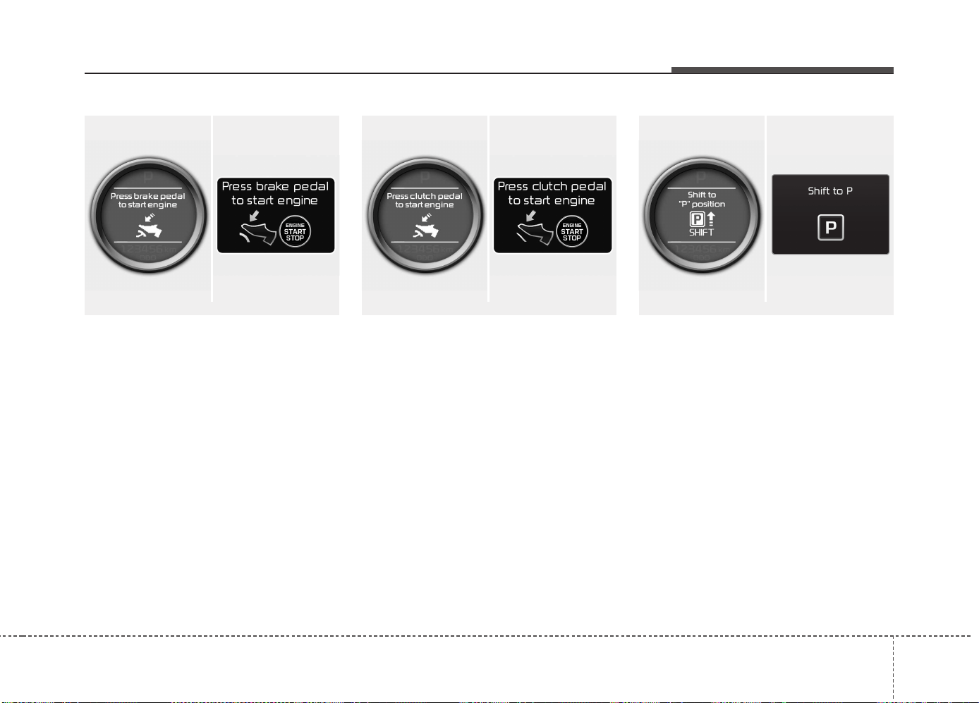
479
Features of your vehicle
Press brake pedal to start engine
(for automatic transaxle)
If the engine start/stop button changes to
the ACC position twice by pressing the
button repeatedly without depressing the
brake pedal, the warning illuminates on
the LCD display for about 10 seconds to
indicate that you should depress the
brake pedal to start the engine.
Press clutch pedal to start engine
(for manual transaxle)
If the engine start/stop button turns to the
ACC position twice by pressing the but-
ton repeatedly without depressing the
clutch pedal, the warning illuminates on
the LCD display for about 10 seconds to
indicate that you should depress the
clutch pedal to start the engine.
Shift to "P" position
(for automatic transaxle)
If you try to turn off the engine without the
shift lever in the P (Park) position, the
engine start/stop button will turn to the
ACC position. If the button is pressed
once more it will turn to the ON position.
The warning illuminates on the LCD dis-
play for about 10 seconds to indicate that
you should press the engine start/stop
button with the shift lever in the P (Park)
position to turn off the engine.
Also, the warning chime sounds for about
10 seconds. (if equipped)
■ Normal vision
■ Supervision
■ Normal vision
■ Supervision
■ Normal vision
■ Supervision
OJD042070/OUM044247L OJD042071/OUM044248L OJD042065/OJD045530L
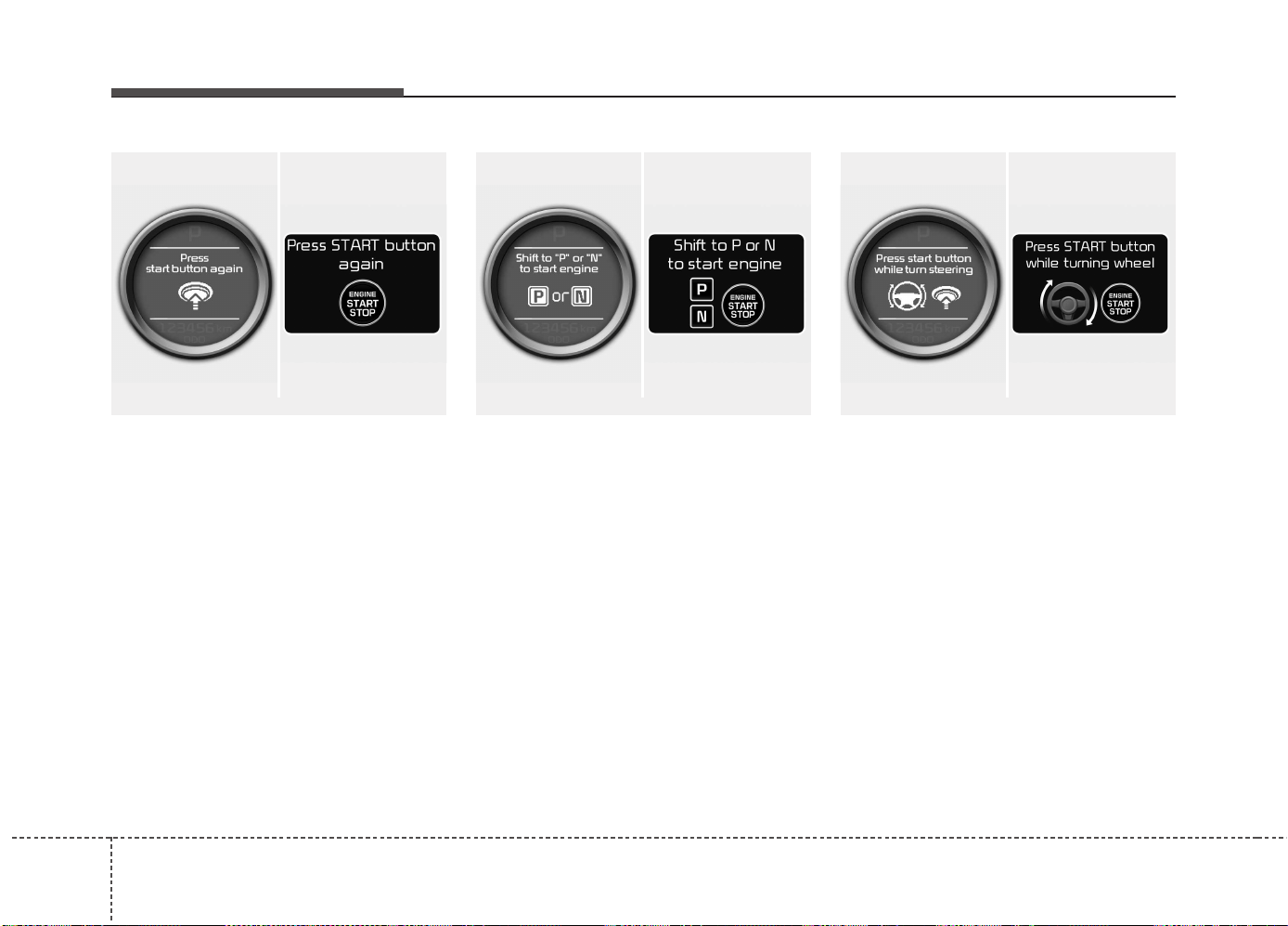
Features of your vehicle
804
Press start button again
If you can not operate the engine
start/stop button when there is a problem
with the engine start/stop button system,
the warning illuminates for 10 seconds
and the chime sounds continuously to
indicate that you could start the engine
by pressing the engine start/stop button
once more.
The chime will stop if the engine
start/stop button system works normally
or the theft alarm system is armed.
If the warning illuminates each time you
press the engine start/stop button, we
recommend that the system be checked
by an authorized Kia dealer.
Shift to "P" or "N" to start engine
If you try to start the engine with the shift
lever not in the P(Park) or N(Neutral)
position, the warning illuminates for
about 10 seconds on the LCD display.
You can also start the engine with the
shift lever in the N(Neutral) position, but
for your safety start the engine with the
shift lever in the P(Park) position.
Press start button while turn steering
(if equipped)
If the steering wheel does not unlock nor-
mally when the engine start/stop button
is pressed, the warning illuminates for 10
seconds on the LCD display. Also, the
warning chime sounds once and the
engine start/stop button light blinks for 10
seconds.
When you are warned, press the engine
start/stop button while turning the steer-
ing wheel right and left.
■ Normal vision
■ Supervision
■ Normal vision
■ Supervision
■ Normal vision
■ Supervision
OJD042074/OUM044251L OJD042077/OUM044253L OJD042067/OUM044270L
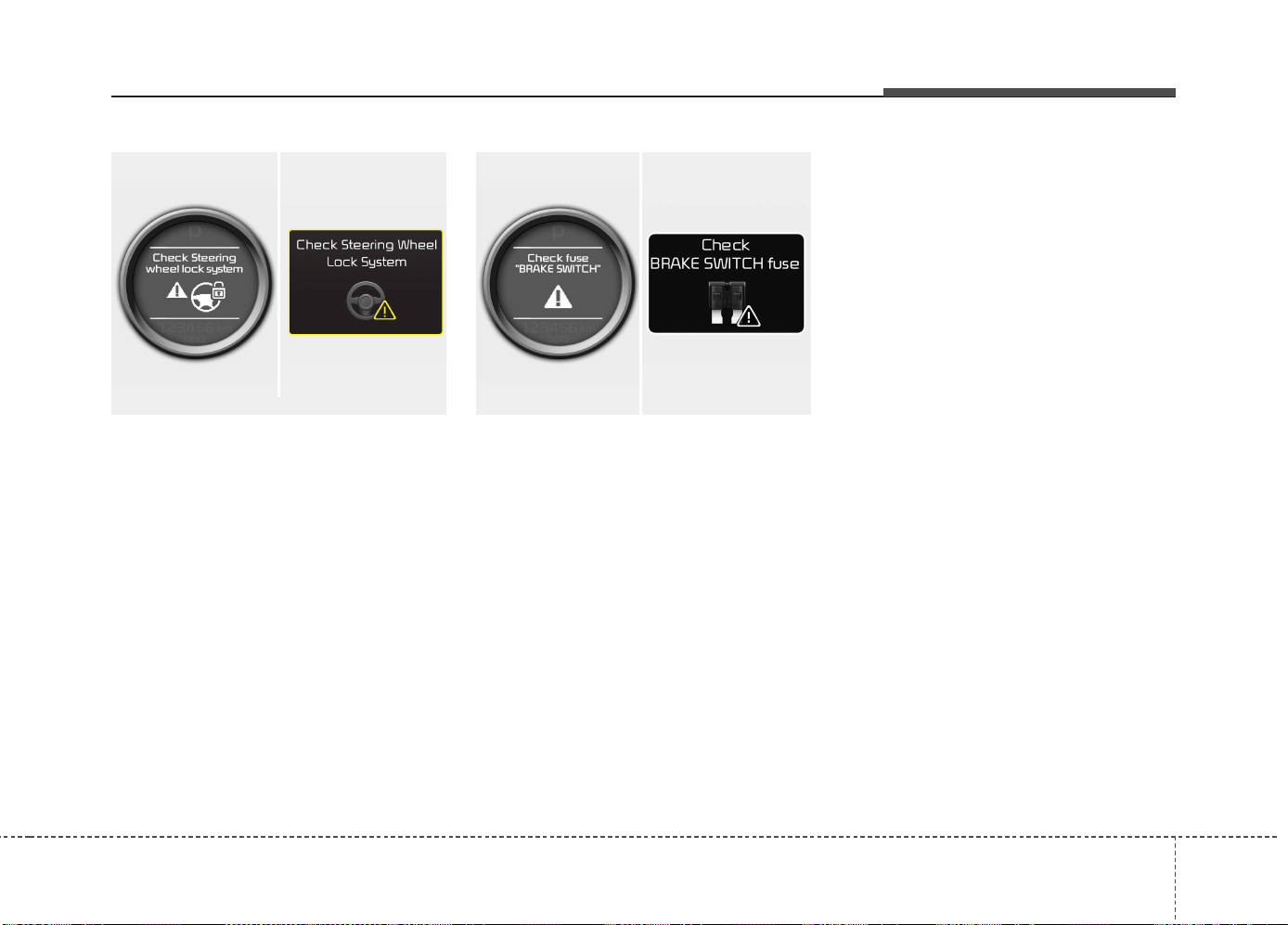
481
Features of your vehicle
Check steering wheel lock system
(if equipped)
If the steering wheel does not lock nor-
mally when the engine start/stop button
changes to the OFF position, the warning
illuminates for 10 seconds on the LCD
display. Also, the warning chime sounds
for 3 seconds and the engine start/stop
button light blinks for 10 seconds.
Check "BRAKE SWITCH" fuse
When the brake switch fuse is discon-
nected, the warning illuminates for 10
seconds on the LCD display.
Replace the fuse with a new one. If that
is not possible you can start the engine
by pressing the engine start/stop button
for 10 seconds in ACC.
Torque reduced due to overheating
(for T-GDI engine)
When the engine coolant temperature
exceeds 115°C, this message will be dis-
played and the torque will be reduced to
protect the engine.
■ Normal vision
■ Supervision
OJD042076/OUM044131L
■ Normal vision
■ Supervision
OJD042069/OUM044275L
Features of your vehicle
824
Warnings and indicators
(Instrument cluster)
All warning lights are checked by turning
the ignition switch ON (do not start the
engine). If any light that does not illumi-
nate, we recommend that the system be
checked by an authorized Kia dealer.
After starting the engine, check to make
sure that all warning lights are off. If any
are still on, this indicates a situation that
needs attention.
The following warning and indicators are
introduced in the previous pages.
• Automatic transaxle/Double clutch trans-
mission shift lever indicator
• Manual transaxle shift indicator
• Parking assist warning (LCD display)
Active ECO indicator
(if equipped)
When the active ECO is operating the
ECO indicator illuminates green. For
more detailed information, refer to
"Active ECO" in chapter 5.
Seat belt warning and
chime light
As a reminder to the driver, the seat belt
warning light will blink or illuminate for
approximately 6 seconds each time you
turn the ignition switch ON regardless of
belt fastening.
For more details, refer to the “Seat belt”
in chapter 3.
Air bag warning light
This warning light will illuminate for
approximately 6 seconds each time you
turn the ignition switch to the ON posi-
tion.
This light also comes on when the SRS
is not working properly. If the air bag
warning light does not come on, or con-
tinuously remains on after operating for
about 6 seconds when you turn the igni-
tion switch to the ON position or started
the engine, or if it comes on while driving,
we recommend that the system be
inspected by an authorized Kia dealer.
ECO
483
Features of your vehicle
Immobilizer indicator
Without smart key system
This indicator illuminates when the
immobilizer key is inserted and turned to
the ON position to start the engine.
At this time, you can start the engine. The
indicator goes out after the engine is run-
ning.
If this indicator blinks when the ignition
switch is in the ON position before start-
ing the engine, we recommend that the
system be checked by an authorized Kia
dealer.
With smart key system
If any of the following occurs in a vehicle
equipped with the smart key, the immobi-
lizer indicator illuminates, blinks or goes
off.
• When the smart key is in the vehicle, if
the engine start/stop button is in the
ACC or ON position, the indicator will
illuminate for approximately 30 sec-
onds to indicate that you are able to
start the engine. However, when the
smart key is not in the vehicle, if the
engine start/stop button is pressed, the
indicator will blink for a few seconds to
indicate that you are not be able to
start the engine.
• If the indicator illuminates only for 2
seconds and goes out when the engine
start/stop button is turned to ON posi-
tion with the smart key in the vehicle,
we recommend that the system be
checked by an authorized Kia dealer.
• When the battery is weak, if the engine
start/stop button is pressed, the indi-
cator will blink and you are not able to
start the engine. However, you are able
to start the engine by pressing the
engine start/stop button directly with
the smart key. Also, if the smart key
system related parts have a problem,
the indicator will blink.
Tailgate open warning light
This warning light illuminates when the
tailgate is not closed securely.
Low fuel level warning
This warning light indicates the fuel tank
is nearly empty. When it comes on, you
should add fuel as soon as possible.
Driving with the fuel level warning light on
or with the fuel level below “O/E” can
cause the engine to misfire and damage
the catalytic converter (if equipped).
Features of your vehicle
844
Electronic Power Steering
(EPS) system warning light
(if equipped)
This indicator light comes on after the
ignition key is turned to the ON position
and then it will go off in approximately 3
seconds if there is no problem with EPS.
This light also comes on when the EPS
has some problems. If it comes on while
driving, we recommend that the system
be checked by an authorized Kia dealer.
Turn signal indicator lights
The blinking green arrows on the instru-
ment panel show the direction indicated
by the turn signals. If the arrow comes on
but does not blink, blinks more rapidly
than normal, or does not illuminate at all,
a malfunction in the turn signal system is
indicated. Your dealer should be consult-
ed for repairs.
Light on indicator
The indicator illuminates when the tail
lights or headlights are ON.
Low Beam Indicator Light
(if equipped)
This indicator light illuminates when the
headlights are on.
High beam indicator
This indicator illuminates when the head-
lights are on and in the high beam posi-
tion or when the turn signal lever is pulled
into the Flash-to-Pass position.
High beam assist indicator
This warning light illuminates :
• When the high-Beam is on with the light
switch in the AUTO light position.
• If your vehicle detects oncoming or
preceding vehicles, the high beam
assist system will switch the high
beam to low beam automatically.
❈ For more details, refer to “High beam
assist” in chapter 4.
485
Features of your vehicle
Adaptive Front
Lighting System (AFLS)
malfunction indicator
(if equipped)
If the AFLS malfunction indicator illumi-
nates, the AFLS is not working properly.
Drive to the nearest safe location and
restart the engine. If the indicator contin-
uously remains on, we recommend that
the system be checked by an authorized
Kia dealer.
Front fog light indicator
(if equipped)
The indicator illuminates when the front
fog lights are ON.
Rear fog light indicator
(if equipped)
This indicator illuminates when the rear
fog lights are ON.
Parking brake & brake
fluid warning
Parking brake warning
This light illuminates when the parking
brake is applied with the ignition switch in
the START or ON position. The warning
light should go off when the parking
brake is released.
Low brake fluid level warning
If the warning light remains on, it may
indicate that the brake fluid level in the
reservoir is low.
If the warning light remains on:
1. Drive carefully to the nearest safe
location and stop your vehicle.
2. With the engine stopped, check the
brake fluid level immediately and add
fluid as required. Then check all brake
components for fluid leaks.
3. Do not drive the vehicle if leaks are
found, the warning light remains on or
the brakes do not operate properly. We
recommend that you contact an
authorized Kia dealer.
AFLS
Features of your vehicle
864
Your vehicle is equipped with dual-diago-
nal braking systems. This means you still
have braking on two wheels even if one
of the dual systems should fail. With only
one of the dual systems working, more
than normal pedal travel and greater
pedal pressure are required to stop the
car. Also, the car will not stop in as short
a distance with only a portion of the
brake system working. If the brakes fail
while you are driving, shift to a lower gear
for additional engine braking and stop the
car as soon as it is safe to do so.
To check bulb operation, check whether
the parking brake and brake fluid warning
light illuminates when the ignition switch
is in the ON position.
Electronic Parking Brake
(EPB) malfunction
indicator (if equipped)
The EPB malfunction indicator will illumi-
nate when the ignition switch is turned
ON, but should go off after approximate-
ly 3 seconds. If the warning light does not
come on, or continuously remains on we
recommend that the system be checked
by an authorized Kia dealer.
Also, the EPB malfunction indicator may
illuminate when the ESC indicator comes
on to indicate that the ESC is not working
properly, but if this occurs, it does not
indicate the EPB has malfunctioned.
For more details, refer to "EPB" in chap-
ter 5.
Anti-lock brake system
(ABS) warning light
This light illuminates if the ignition switch
is turned ON and goes off in approxi-
mately 3 seconds if the system is operat-
ing normally.
If the ABS warning light remains on,
comes on while driving, or does not
come on when the ignition switch is
turned to the ON position, this indicates
that there may be a problem with the
ABS.
If this occurs, we recommend that the
system be checked by an authorized Kia
dealer. The normal braking system will
still be operational, but without the assis-
tance of the anti-lock brake system.
WARNING
Driving the vehicle with a warning
light on is dangerous. If the brake
warning light remains on, we recom-
mend that the system be checked by
an authorized Kia dealer.
EPB
487
Features of your vehicle
Electronic brake
force distribution
(EBD) system
warning light
If two warning lights illuminate at the
same time while driving, your vehicle’s
ABS and EBD system may have mal-
functioned.
In this case, your ABS and regular brake
system may not work normally. We rec-
ommend that the system be checked by
an authorized Kia dealer.
✽✽
NOTICE
If the ABS warning light or EBD warn-
ing light is on and stays on, the
speedometer or odometer/tripmeter
may not work. Also, the EPS warning
light may illuminate and the steering
effort may increase or decrease. In this
case, we recommend that the system be
checked by an authorized Kia dealer.
Electronic Stability Control
(ESC) indicator
(if equipped)
The ESC indicator will illuminate when
the ignition switch is turned ON, but
should go off after approximately 3 sec-
onds. When the ESC is on, it monitors
the driving conditions. Under normal driv-
ing conditions, the ESC indicator will
remain off. When a slippery or low trac-
tion condition is encountered, the ESC
will operate, and the ESC indicator will
blink to indicate the ESC is operating.
But, if the ESC system malfunctions the
indicator illuminates and stays on. We
recommend that the system be checked
by an authorized Kia dealer.
ESC OFF indicator
(if equipped)
The ESC OFF indicator will illuminate
when the ignition switch is turned ON,
but should go off after approximately 3
seconds. To switch to ESC OFF mode,
press the ESC OFF button. The ESC
OFF indicator will illuminate indicating
the ESC is deactivated.
WARNING
If both ABS and Brake warning
lights are on and stay on, your vehi-
cle’s brake system will not work
normally. So you may experience
an unexpected and dangerous situ-
ation during sudden braking. In this
case, avoid high speed driving and
abrupt braking except an emer-
gency situation.
We recommend that the system be
checked by an authorized Kia dealer.
Features of your vehicle
884
Auto stop indicator
(if equipped)
This indicator will illuminate when the
engine enters the Idle Stop mode of the
ISG (Idle Stop and Go) system.
When the automatic starting occurrs, the
auto stop indicator on the cluster will
blink for 5 seconds.
For more details, refer to the ISG (Idle
Stop and Go) system in chapter 5.
For vehicles equipped with instrument
cluster type B, the indicator illuminates
on the LCD display.
✽✽
NOTICE
When the engine automatically starts by
the ISG system, some warning lights
(ABS, ESC, ESC OFF, EPS or Parking
brake warning light) may turn on for a
few seconds.
This happens because of low battery
voltage. It does not mean the system is
malfunctioning.
Cruise indicator (if equipped)
CRUISE indicator
The indicator illuminates when the cruise
control system is enabled.
The cruise indicator in the instrument
cluster is illuminated when the cruise
control ON-OFF button on the steer-
ing wheel is pushed.
The indicator goes off when the cruise
control ON-OFF button is pushed
again. For more information about the
use of cruise control, refer to “Cruise
control system” in chapter 5.
Cruise SET indicator
The indicator illuminates when the cruise
control switch (SET- or RES+) is ON.
The cruise SET indicator in the instru-
ment cluster illuminats when the cruise
control switch (SET- or RES+) is pushed.
The cruise SET indicator does not illumi-
nate when the cruise control cancel but-
ton O is pushed or the system is disen-
gaged.
Charging system warning
light
This warning light indicates a malfunction
of either the generator or electrical
charging system.
If the warning light comes on while the
vehicle is in motion:
1. Drive to the nearest safe location.
2. With the engine off, check the genera-
tor drive belt for looseness or break-
age.
3. If the belt is adjusted properly, a prob-
lem exists somewhere in the electrical
charging system. We recommend that
the system be checked by an author-
ized Kia dealer.
SET
489
Features of your vehicle
Tire Pressure Monitoring System
(TPMS) indicator (if equipped)
Low tire pressure telltale/
TPMS malfunction indicator
The low tire pressure telltale comes on
for 3 seconds after the ignition switch is
turned to the ON position.
The low tire pressure and position tell-
tales illuminates when one or more of
your tires is significantly underinflated.
The TPMS malfunction indicator will illu-
minate after it blinks for approximately
one minute when there is a problem with
the Tire Pressure Monitoring System.
If this occurs, we recommend that the
system be checked by an authorized Kia
dealer.
For more details, refer to the TPMS in
chapter 6.
The low tire pressure position telltale illu-
minates on the LCD display.
Engine oil pressure warn-
ing
This warning light indicates the engine oil
pressure is low.
If the warning light illuminates while driv-
ing:
1. Drive safely to the side of the road and
stop.
2. With the engine off, check the engine
oil level. If the level is low, add oil as
required.
If the warning light remains on after
adding oil or if oil is not available, we rec-
ommend that you call an authorized Kia
dealer.
WARNING - Safe stopping
• The TPMS cannot alert you to
severe and sudden tire damage
caused by external factors.
• If you notice any vehicle instabili-
ty, immediately take your foot off
the accelerator pedal, apply the
brakes gradually and with light
force, and slowly move to a safe
position off the road.
CAUTION
If the engine does not stop immedi-
ately after the engine oil pressure
warning light is illuminated, severe
damage could result.
Features of your vehicle
904
Engine oil level warning
light (if equipped, for diesel)
The engine oil level warning light illumi-
nates when the engine oil level should be
checked.
If the warning light comes on, check the
engine oil level as soon as possible and
add engine oil as required.
Slowly pour the recommended oil little by
little into a funnel. (Oil refill capacity :
approximately 0.6 ~ 1.0 l)
Use only the specified engine oil. (Refer
to "Recommended lubricants and capac-
ities" in chapter 8.)
Do not overfill the engine oil to ensure
the oil level is not above F mark on the
dipstick.
✽✽
NOTICE
• If you travel approximately 50
km~100 km after the engine warms
up, after adding the engine oil, the
warning light will go off.
• Cycle the ignition from OFF to ON 3
times within 10 seconds, the warning
light will go off immediately. However,
when you turn off the warning light
without adding the engine oil, the light
will come on again after traveling
approximately 50 km ~ 100 km after
the engine warms up.
CAUTION
If the oil pressure warning light
stays on while the engine is run-
ning, serious engine damage may
result. The oil pressure warning
light comes on whenever there is
insufficient oil pressure. In normal
operation, it should come on when
the ignition switch is turned on, then
go out when the engine is started. If
the oil pressure warning light stays
on while the engine is running, there
is a serious malfunction.
If this happens, stop the car as soon
as it is safe to do so, turn off the
engine and check the oil level. If the
oil level is low, fill the engine oil to
the proper level and start the engine
again. If the light stays on with the
engine running, turn the engine off
immediately. In any instance where
the oil light stays on when the
engine is running, we recommend
that the system be checked by an
authorized Kia dealer.
CAUTION
If the light comes on continuously
after adding the engine oil and trav-
eling approximately 50 km~100 km
after the engine warms up, we rec-
ommend that the system be checked
by an authorized Kia dealer.
Even if this light doesn't come on
after the engine has started, the
engine oil should be checked and
supplied periodically.
491
Features of your vehicle
Malfunction indicator lamp
(MIL) (check engine light)
This indicator light is part of the Engine
Control System which monitors various
emission control system components. If
this light illuminates while driving, it indi-
cates that a potential problem has been
detected somewhere in the emission
control system.
This light will also illuminate when the
ignition switch is turned to the ON posi-
tion, and will go out in a few seconds
after the engine is started. If it illuminates
while driving, or does not illuminate when
the ignition key is turned to the ON posi-
tion, we recommend that the system be
checked by an authorized Kia dealer.
Generally, your vehicle will continue to be
drivable, but we recommend that the sys-
tem be checked by an authorized Kia
dealer.
CAUTION
Prolonged driving with the Emission
Control System Malfunction
Indicator Light illuminated may
cause damage to the emission con-
trol systems which could effect dri-
vability and/or fuel economy.
CAUTION -
Gasoline engine
If the Emission Control System
Malfunction Indicator Light illumi-
nates, potential catalytic converter
damage is possible which could
result in loss of engine power. We
recommend that the system be
inspected by an authorized Kia
dealer.
CAUTION - Diesel engine
(if equipped with DPF)
When the malfunction indicator light
blinks, it may stop blinking after driv-
ing the vehicle at more than 60km/h
(37 mph) or at more than second
gear with 1500 ~ 2500 engine rpm for
a certain time (for about 25 minutes).
If the malfunction indicator light
continues to blink in spite of the
procedure, we recommend that the
system be checked by an author-
ized Kia dealer.
If you continue to drive with the
malfunction indicator light blinking
for a long time, the DPF system can
be damaged and fuel consumption
can worsen.
CAUTION -
Diesel engine
If the Emission Control System
Malfunction Indicator Light blinks,
some error related to the injection
quantity adjustment occurs which
could result in loss of engine
power, combustion noise and poor
emission. We recommend that the
system be inspected by an author-
ized Kia dealer.
Features of your vehicle
924
Engine coolant tempera-
ture warning light
(if equipped)
The warning light illuminates if the tem-
perature of the engine coolant is above
120±3°C (248±5.4°F).
Do not continue driving with an overheat-
ed engine. If your vehicle overheats, refer
to “Overheating” in chapter 6.
✽✽
NOTICE
If the engine coolant temperature warn-
ing light illuminates, it indicates over-
heating that may damage the engine.
Glow indicator
(Diesel engine)
The indicator light illuminates when the
ignition switch is placed at the ON posi-
tion. The engine can be started after the
preheat indicator light goes off. The illu-
minating time varies with the water tem-
perature, air temperature and battery
condition.
✽✽
NOTICE
If the engine does not start within 10
seconds after the preheating is complet-
ed, turn the ignition key once more to
the LOCK/OFF position for 10 seconds,
and then to the ON position, in order to
preheat again.
Fuel filter warning light
(Diesel engine)
This warning light illuminates for 3 sec-
onds after the ignition switch is set to the
ON position and then it will go out. If it
lights up while the engine is running, it
indicates that water has accumulated
inside the fuel filter. If this happens,
remove the water from the fuel filter.
For more details, refer to “Fuel filter” in
chapter 7.
CAUTION
If the preheat indicator light contin-
ues to illuminate or flash on and off
after the engine has warmed up or
while driving, we recommend that
the system be checked by an
authorized Kia dealer.
CAUTION
When the fuel filter warning light
illuminates, engine power (vehicle
speed & idle speed) may decrease.
If you keep driving with the warning
light on, you can damage your vehi-
cle's engine parts and injection sys-
tem of the Common Rail. If this
occurs, we recommend that the
system be checked by an author-
ized Kia dealer.
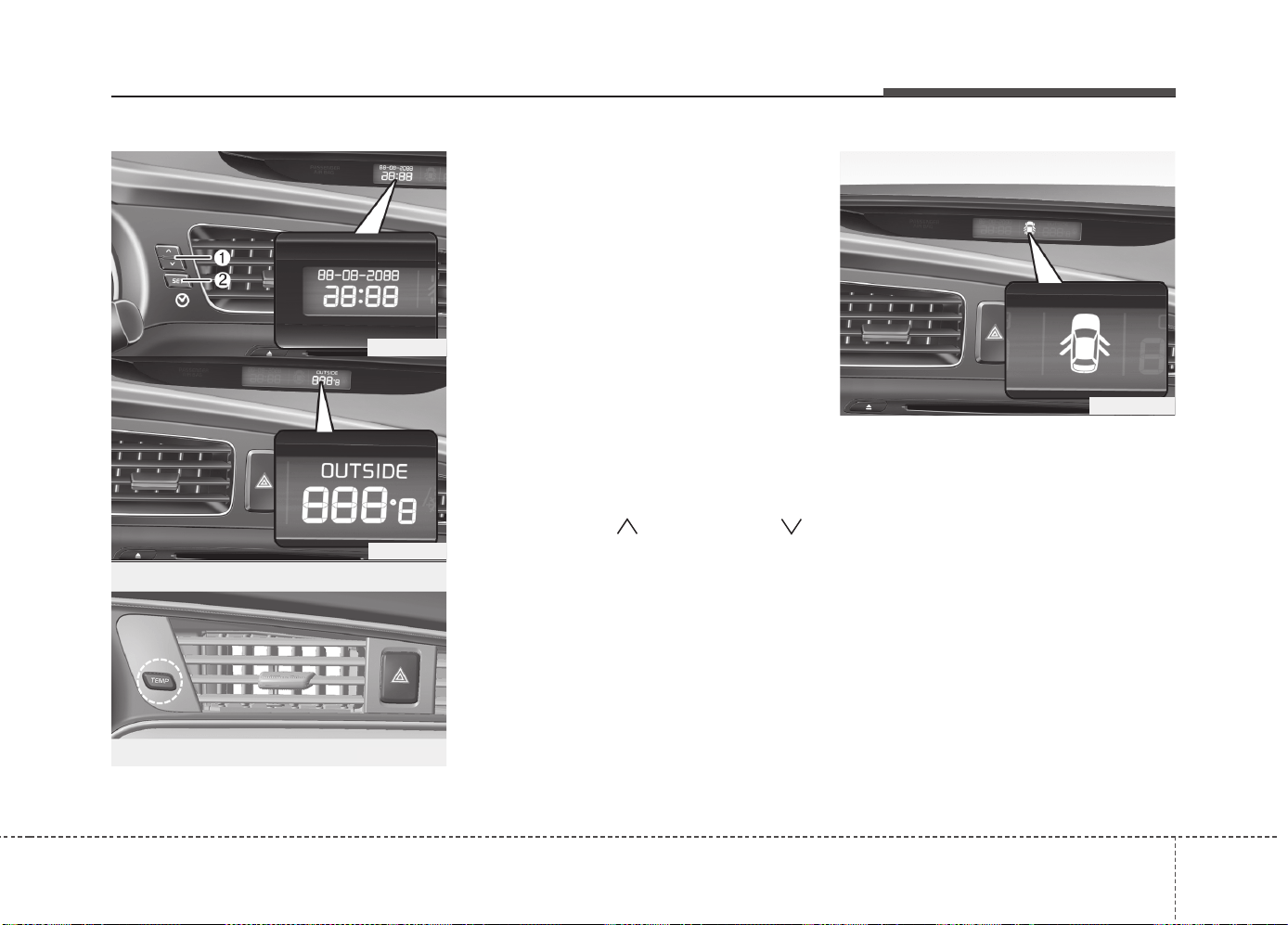
493
Features of your vehicle
LCD DISPLAY WARNINGS AND INDICATORS (INSTRUMENT PANEL DISPLAY)
Calendar / Clock / Outside ambi-
ent Temperature (if equipped)
The monitor will display the outside ambi-
ent temperature, date and time.
To change the date, time or temperature
unit(°C ↔ °F), press the SET(2) or Temp
button for more than 1 seconds.
Then you will enter the set-up mode and
mode changes in the following order as
you press the SET (2) button less than 1
second.
HOUR → MINUTE → YEAR → MONTH
→ DAY → 12H/24H → TEMPERATURE
UNIT CHANGE → Escape set-up mode
Press the SET (2) button less than 1 sec-
ond to select the mode and set the data
using the UP (1, ) and DOWN (1, )
button while the selected setting mode
blinks.
To cancel the SET UP mode, do one of
the following :
- Press the SET button less than 1 sec-
ond in set-up temperature unit change
mode
- Press the SET button more than 1 sec-
ond in any set-up mode
- After 15 seconds without any key press
- Ignition is On or OFF in Set-up mode
- Battery is disconnected
Door and tailgate open display
The monitor will display the correspon-
ding door or tailgate that is not closed
securely.
OJD042143
OJD042142
OJD042145
OJD045534L
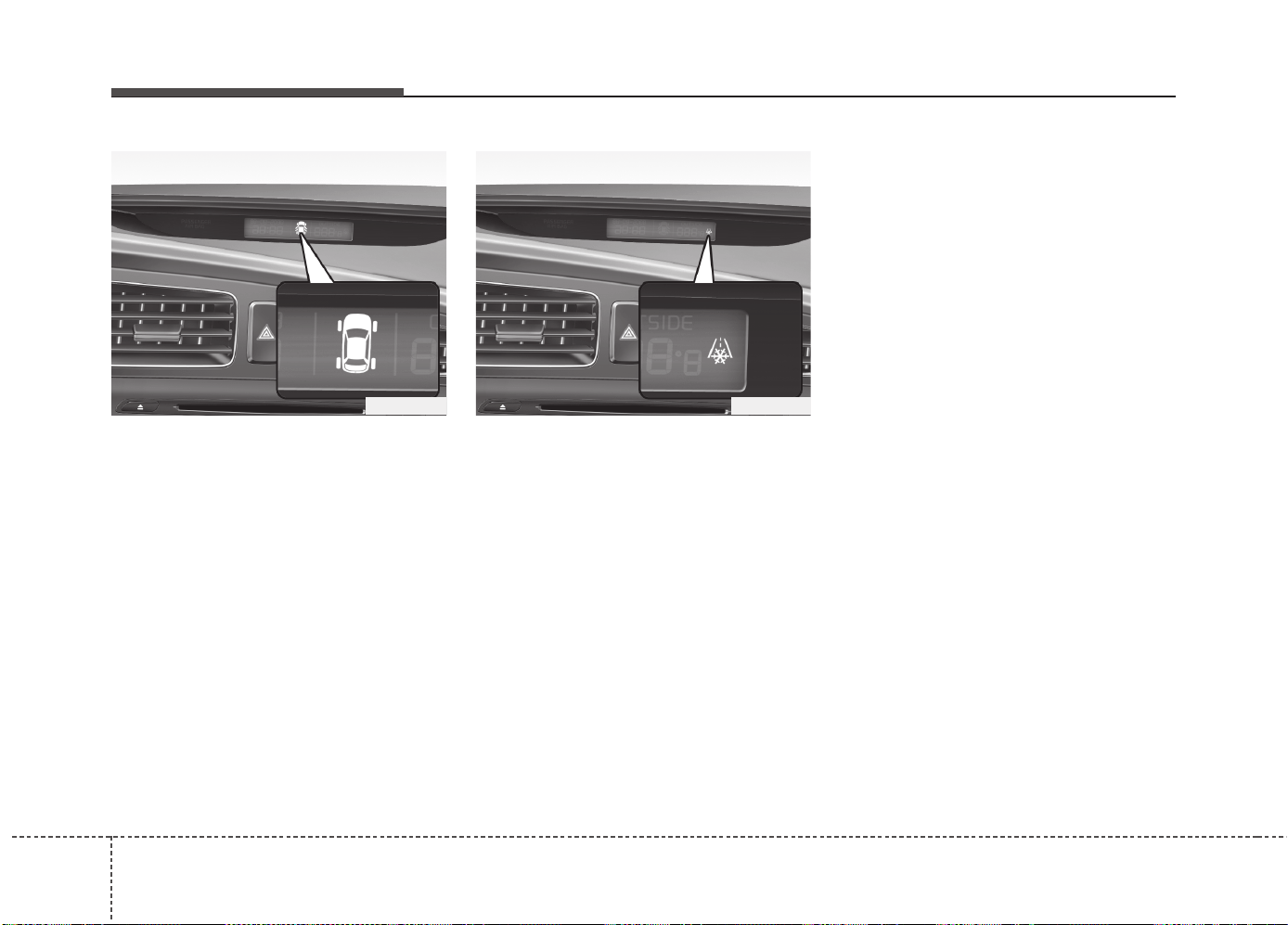
Features of your vehicle
944
TPMS (if equipped)
The monitor will display the correspon-
ding tire that is low with pressure.
For details, see Tire Pressure Monitoring
System on chapter 6.
Icy road warning light
(if equipped)
This warning light is to warn the driver
the road may be icy when:
• Ignition ON
• Temperature range: approximately below
4°C (39.2°F).
The warning light will blink for 10 sec-
onds and then illuminate. Also, the warn-
ing chime will sound.
✽✽
NOTICE
If the icy road warning light appears
while driving, you should drive more
attentively and safely refraining from
over-speeding, rapid acceleration, sud-
den braking or sharp turning, etc.
OJD042144 OJD042146
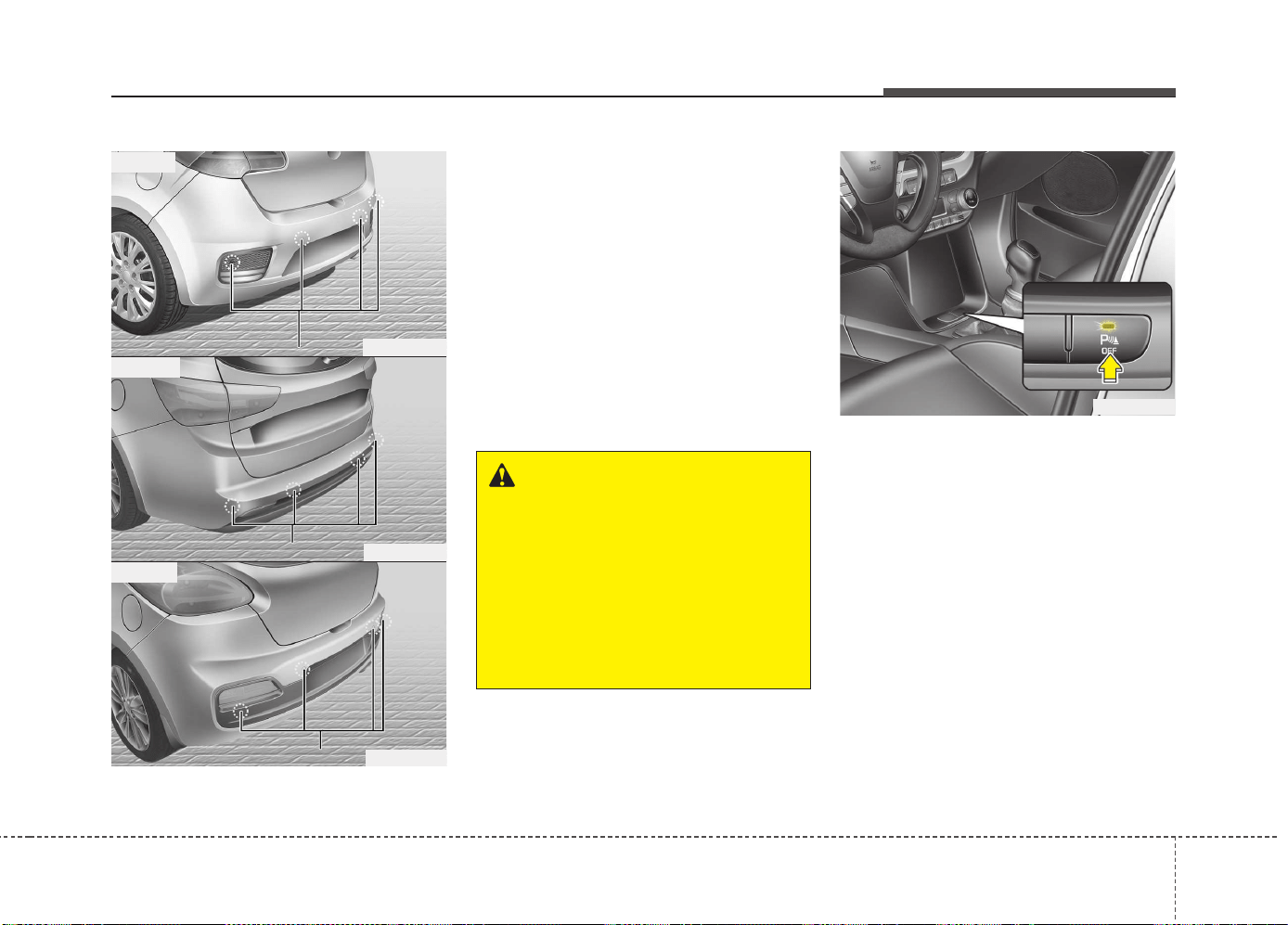
495
Features of your vehicle
The rear parking assist system assists
the driver during backward movement of
the vehicle by chiming if any object is
sensed within a distance of 120 cm (47
in.) behind the vehicle. This system is a
supplemental system and it is not intend-
ed to nor does it replace the need for
extreme care and attention of the driver.
The sensing range and objects
detectable by the back sensors are limit-
ed. Whenever backing-up, pay as much
attention to what is behind you as you
would in a vehicle without a rear parking
assist system.
Operation of the rear parking
assist system
Operating condition
• This system will activate when the indi-
cator on the rear parking assist OFF
button is not illuminated.
If you desire to deactivate the rear
parking assist system, press the rear
parking assist OFF button again. (The
indicator on the button will illuminate.)
To turn the system on, press the button
again. (The indicator on the button will
go off.)
• This system will activate when backing
up with the ignition switch ON.
If the vehicle is moving at a speed over
5 km/h (3 mph), the system may not be
activated correctly.
REAR PARKING ASSIST SYSTEM (IF EQUIPPED)
WARNING
The rear parking assist system is a
supplementary function only. The
operation of the rear parking assist
system can be affected by several
factors (including environmental
conditions). It is the responsibility
of the driver to always check the
area behind the vehicle before and
while backing up.
OJD042080
OJD045084
OJD042242
OJD043243
■ Wagon
■ 5 Door
■ 3 Door
SS
SS
ee
ee
nn
nn
ss
ss
oo
oo
rr
rr
ss
ss
SS
SS
ee
ee
nn
nn
ss
ss
oo
oo
rr
rr
ss
ss
SS
SS
ee
ee
nn
nn
ss
ss
oo
oo
rr
rr
ss
ss
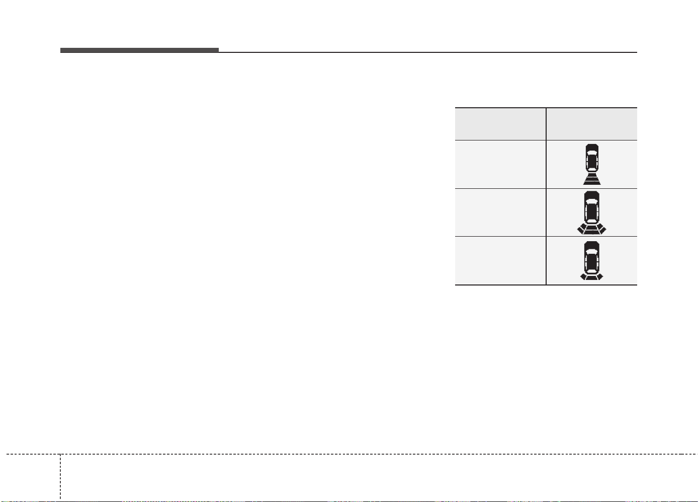
Features of your vehicle
964
• The sensing distance while the rear
parking assist system is in operation is
approximately 120 cm (47 in.).
• When more than two objects are
sensed at the same time, the closest
one will be recognized first.
Types of warning sound
• When an object is 120 cm to 61 cm (47
in. to 23.6 in.) from the rear bumper:
Buzzer beeps intermittently
• When an object is 60 cm to 31 cm
(23.6 in. to 12.2 in.) from the rear
bumper: Buzzer beeps more frequent-
ly
• When an object is within 30 cm (11.8
in.) of the rear bumper:
Buzzer sounds continuously.
Type of the warning indicator
(if equipped)
*1: It indicates the range of sensed object
by each sensor. (Left, Center, Right)
❈ In case the object is between or close
to the sensors, the indicator could be
different.
Distance from
object
Warning indicator
61cm ~ 120 cm
(24 in. ~ 47 in.)
31cm ~ 60 cm
(12.2 in. ~ 23.6 in.)
Less than 30 cm
(11.8 in.)
*
1
*
1
*
1

497
Features of your vehicle
Non-operational conditions of
rear parking assist system
The rear parking assist system may
not operate properly when:
1. Moisture is frozen to the sensor. (It will
operate normally when the moisture
has been cleared.)
2. The sensor is covered with foreign
matter, such as snow or water, or the
sensor cover is blocked. (It will operate
normally when the material is removed
or the sensor is no longer blocked.)
3. Driving on uneven road surfaces
(unpaved roads, gravel, bumps, gradi-
ent).
4. Objects generating excessive noise
(vehicle horns, loud motorcycle
engines, or truck air brakes) are within
range of the sensor.
5. Heavy rain or water spray exists.
6. Wireless transmitters or mobile
phones are within range of the sensor.
7. Trailer towing.
The detecting range may decrease
when:
1. The sensor is stained with foreign mat-
ter such as snow or water. (The sens-
ing range will return to normal when
removed.)
2. Outside air temperature is extremely
hot or cold.
The following objects may not be rec-
ognized by the sensor:
1. Sharp or slim objects such as ropes,
chains or small poles.
2. Objects which tend to absorb the sen-
sor frequency such as clothes, spongy
material or snow.
3. Undetectable objects smaller than 1 m
(40 in.) and narrower than 14 cm (6 in.)
in diameter.
Rear parking assist system pre-
cautions
• The rear parking assist system may
not sound sequentially depending on
the speed and shapes of the objects
detected.
• The rear parking assist system may
malfunction if the vehicle bumper
height or sensor installation has been
modified or damaged. Any non-factory
installed equipment or accessories
may also interfere with the sensor per-
formance.
• The sensor may not recognize objects
less than 30 cm (11.8 in.) from the sen-
sor, or it may sense an incorrect dis-
tance. Use caution.
• When the sensor is frozen or stained
with snow, dirt, or water, the sensor
may be inoperative until the stains are
removed using a soft cloth.
• Do not push, scratch or strike the sen-
sor. Sensor damage could occur.
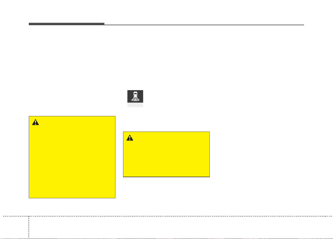
Features of your vehicle
984
✽✽
NOTICE
This system can only sense objects with-
in the range and location of the sensors;
it can not detect objects in other areas
where sensors are not installed. Also,
small or slim objects, such as poles or
objects located between sensors may not
be detected by the sensors.
Always visually check behind the vehi-
cle when backing up.
Be sure to inform any drivers of the
vehicle that may be unfamiliar with the
system regarding the systems capabili-
ties and limitations.
Self-diagnosis
When you shift the gear to the R
(Reverse) position and if one or more of
the below occurs you may have a mal-
function in the rear parking assist sys-
tem.
• You don't hear an audible warning
sound or if the buzzer sounds intermit-
tently.
If this occurs, we recommend that the
system be checked by an authorized Kia
dealer.
WARNING
Pay close attention when the vehi-
cle is driven close to objects on the
road, particularly pedestrians, and
especially children. Be aware that
some objects may not be detected
by the sensors, due to the object’s
distance, size or material, all of
which can limit the effectiveness of
the sensor. Always perform a visu-
al inspection to make sure the vehi-
cle is clear of all obstructions
before moving the vehicle in any
direction.
WARNING
Your new vehicle warranty does not
cover any accidents or damage to
the vehicle or injuries to its occu-
pants due to a rear parking assist
system malfunction. Always drive
safely and cautiously.
(blinks)
• is displayed. (if equipped)
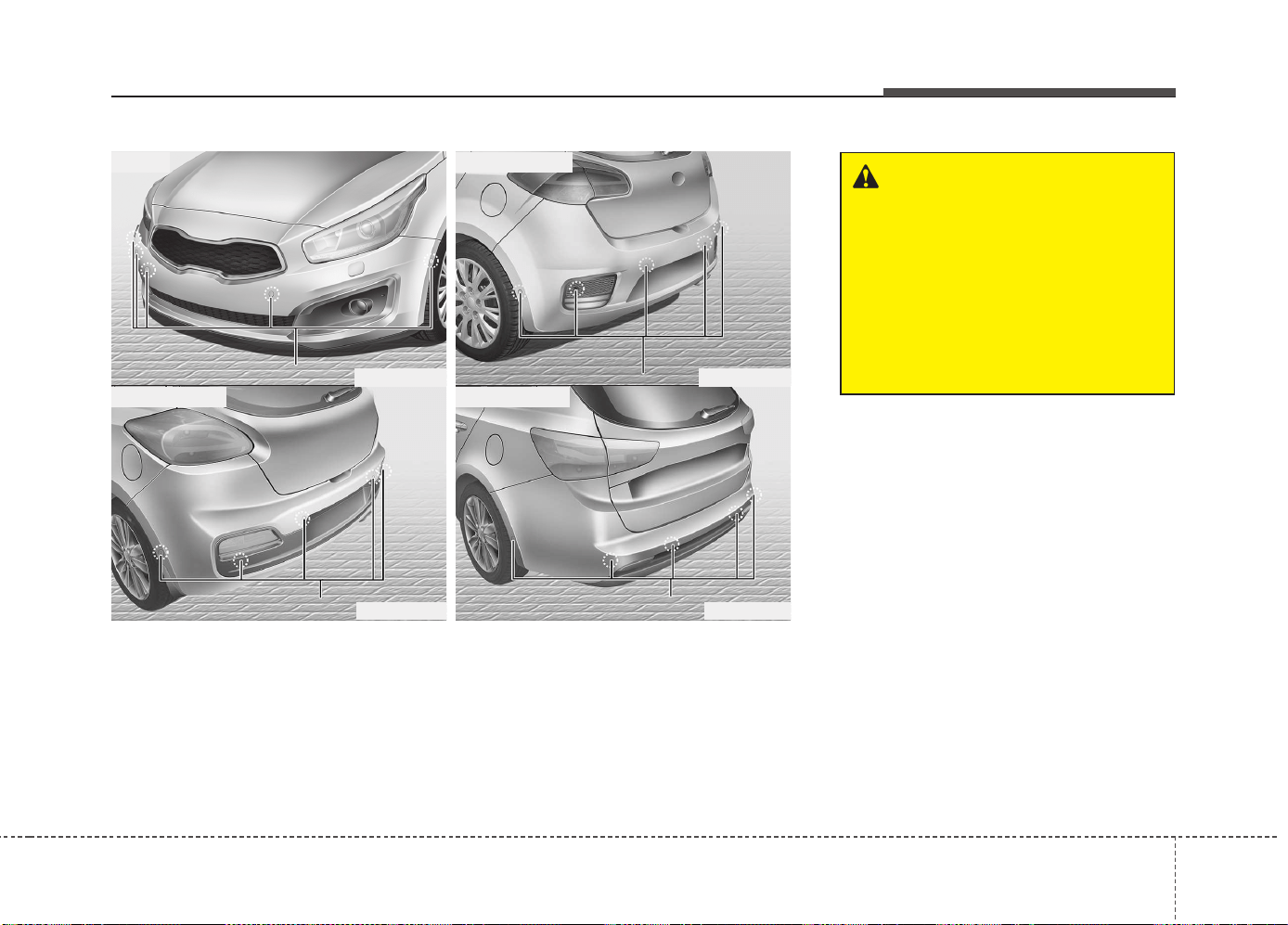
499
Features of your vehicle
PARKING ASSIST SYSTEM (IF EQUIPPED)
WARNING
The parking assist system should
only be considered as a supple-
mentary function. The driver must
check the front and rear view. The
operational function of the parking
assist system can be affected by
many factors and conditions of the
surroundings, so the responsibility
rests always with the driver.
OJD045243L
■ Rear (3 Door)
■ Front
OJD045085L
OJD045242L
■ Rear (Wagon)
■ Rear (5 Door)
OJD045084L
The parking assist system assists the driver during movement of the vehicle by chim-
ing or displaying the area an obstacle is detected on the instrument cluster if any
object is sensed within the distance of 100 cm (39.4 in.) in front and 120 cm (47 in.)
behind the vehicle.
This system is a supplemental system and it is not intended to nor does it replace the
need for extreme care and attention of the driver.
The sensing range and objects detectable by the sensors are limited.
Whenever moving pay as much attention to what is in front and behind of you as you
would in a vehicle without a parking assist system.
SS
SS
ee
ee
nn
nn
ss
ss
oo
oo
rr
rr
ss
ss
SS
SS
ee
ee
nn
nn
ss
ss
oo
oo
rr
rr
ss
ss
SS
SS
ee
ee
nn
nn
ss
ss
oo
oo
rr
rr
ss
ss
SS
SS
ee
ee
nn
nn
ss
ss
oo
oo
rr
rr
ss
ss
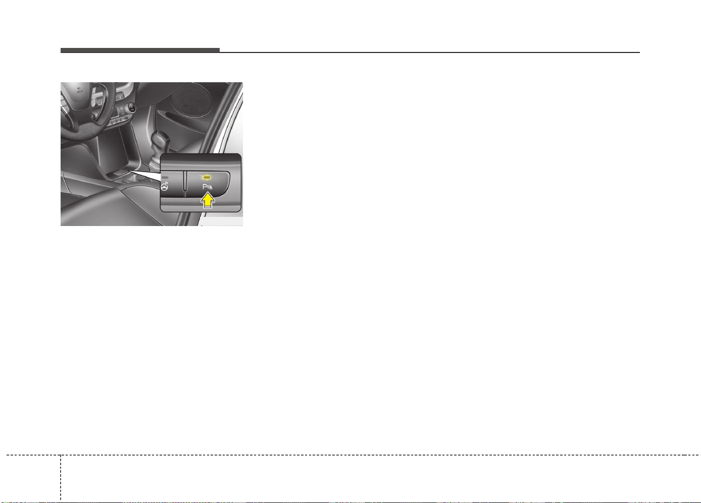
Features of your vehicle
1004
Operation of the parking assist
system
Operating condition
• This system activates when the park-
ing assist system button is pressed
with the ignition switch ON.
Type A
The indicator of the parking assist sys-
tem button turns on automatically and
activates the parking assist system when
you shift the gear to the R(Reverse) posi-
tion or press the SPAS button. It will turn
off automatically when you drive above
40 km/h(24.8 mph) except in the case
when the parking assist system button is
pressed with the ignition switch ON.
Type B
The indicator of the parking assist sys-
tem button turns on automatically and
activates the parking assist system when
you shift the gear to the R(Reverse) posi-
tion or press the SPAS button. It will turn
off automatically when you drive above
40 km/h(24.8 mph).
• If the vehicle speed is above 10km/h
(6.2 mph), the parking assist system
will not operate.
• The sensing distance while moving for-
ward is approximately 100 cm (39.4 in.)
when you are driving less than 10 km/h
(6.2 mph).
• When more than two objects are
sensed at the same time, the closest
one will be recognized first.
✽✽
NOTICE
It may not operate if it’s distance from
the object is already less than approxi-
mately 25 cm when the system is ON.
OJD042081
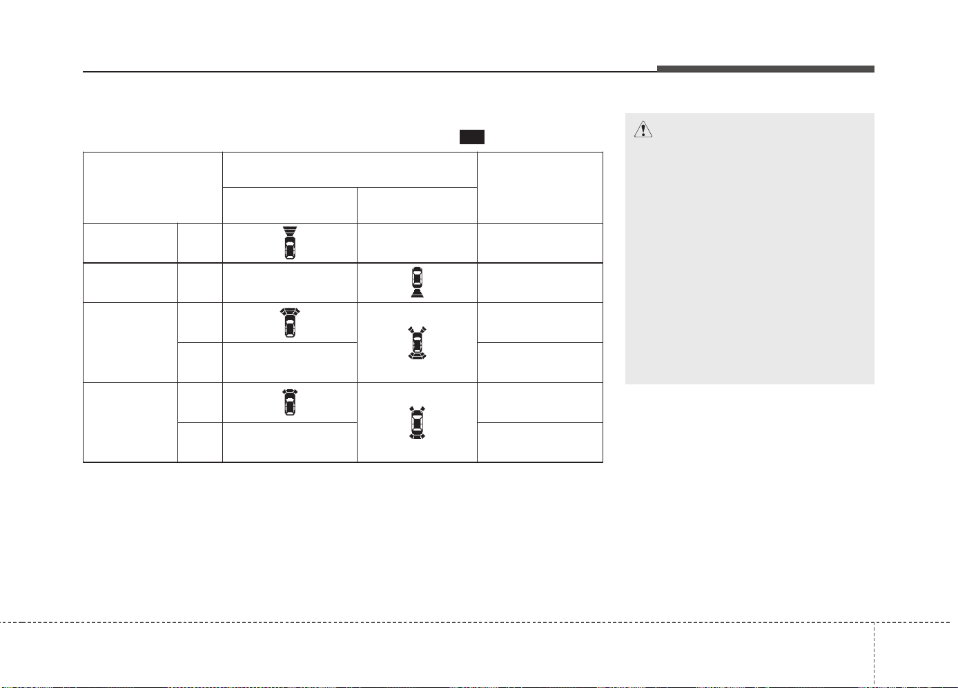
4101
Features of your vehicle
✽✽
NOTICE
• The actual warning sound and indicator may differ from the illustration accord-
ing to objects or sensor status.
• Do not wash the vehicle's sensor with high pressure water.
• When driving rearward(at “R’ shift), Side sensor operates and if detecting some
object at the side, warning indicator displays at front corner.
Type of warning indicator and sound
: with Warning sound
Distance from object
Warning indicator
Warning sound
When driving
forward
When driving
rearward
100cm~61cm Front -
Buzzer beeps
intermittently
120cm~61cm Rear -
Buzzer beeps
intermittently
60cm~31cm
Front
Buzzer beeps
frequently
Rear -
Buzzer beeps
frequently
30cm
Front
Buzzer sounds
continuously
Rear -
Buzzer sounds
continuously
CAUTION
• This system can only sense
objects within the range and loca-
tion of the sensors;
It can not detect objects in other
areas where sensors are not
installed. Also, small or slim
objects, such as poles or objects
located between sensors may not
be detected by the sensors.
Always visually check behind the
vehicle when backing up.
• Be sure to inform any drivers of
the vehicle that may be unfamiliar
with the system regarding the sys-
tems capabilities and limitations.

Features of your vehicle
1024
Non-operational conditions of
parking assist system
Parking assist system may not oper-
ate normally when:
1. Moisture is frozen to the sensor. (It will
operate normally when moisture
melts.)
2. Sensor is covered with foreign matter,
such as snow or water, or the sensor
cover is blocked. (It will operate nor-
mally when the material is removed or
the sensor is no longer blocked.)
3. Sensor is stained with foreign matter
such as snow or water. (Sensing range
will return to normal when removed.)
4.The parking assist button is off.
There is a possibility of parking
assist system malfunction when:
1. Driving on uneven road surfaces such
as unpaved roads, gravel, bumps, or
gradient.
2. Objects generating excessive noise
such as vehicle horns, loud motorcycle
engines, or truck air brakes can inter-
fere with the sensor.
3. Heavy rain or water spray.
4. Wireless transmitters or mobile
phones present near the sensor.
5. Sensor is covered with snow.
Detecting range may decrease when:
1. Outside air temperature is extremely
hot or cold.
2. Undetectable objects smaller than 1 m
and narrower than 14 cm in diameter.
The following objects may not be rec-
ognized by the sensor:
1. Sharp or slim objects such as ropes,
chains or small poles.
2. Objects, which tend to absorb sensor
frequency such as clothes, spongy
material or snow.
✽✽
NOTICE
1. The warning may not sound sequen-
tially depending on the speed and
shapes of the objects detected.
2. The parking assist system may mal-
function if the vehicle bumper height
or sensor installation has been modi-
fied. Any non-factory installed equip-
ment or accessories may also interfere
with the sensor performance.
3. Sensor may not recognize objects less
than 30 cm from the sensor, or it may
sense an incorrect distance. Use with
caution.
4. When the sensor is frozen or stained
with snow or water, the sensor may be
inoperative until the stains are
removed using a soft cloth.
5. Do not push, scratch or strike the sen-
sor with any hard objects that could
damage the surface of the sensor.
Sensor damage could occur.
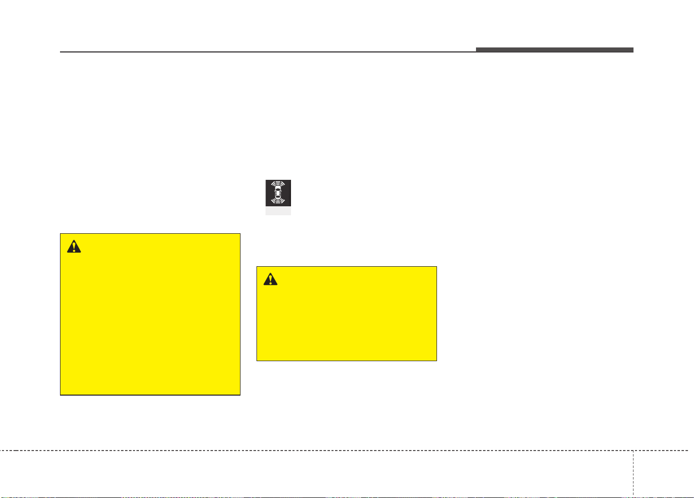
4103
Features of your vehicle
✽✽
NOTICE
This system can only sense objects with-
in the range and location of the sensors,
it can not detect objects in other areas
where sensors are not installed. Also,
small or slim objects, or objects located
between sensors may not be detected.
Always visually check in front and
behind the vehicle when driving.
Be sure to inform any drivers in the
vehicle that may be unfamiliar with the
system regarding the systems capabili-
ties and limitations.
Self-diagnosis
When you shift the gear to the R
(Reverse) position and if one or more of
the below occurs you may have a mal-
function in the parking assist system.
• You don't hear an audible warning
sound or if the buzzer sounds intermit-
tently.
If this occurs, we recommend that the
system be checked by an authorized Kia
dealer.
WARNING
Your new vehicle warranty does not
cover any accidents or damage to
the vehicle or injuries to its occu-
pants related to a parking assist
system. Always drive safely and
cautiously.
WARNING
Pay close attention when the vehi-
cle is driven close to objects on the
road, particularly pedestrians, and
especially children. Be aware that
some objects may not be detected
by the sensors, due to the objects
distance, size or material, all of
which can limit the effectiveness of
the sensor. Always perform a visual
inspection to make sure the vehicle
is clear of all obstructions before
moving the vehicle in any direction.
(blinks)
• is displayed. (if equipped)
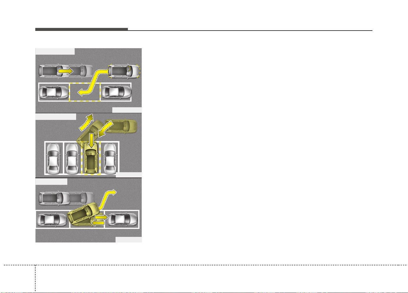
Features of your vehicle
1044
The Smart Parking Assist System helps
drivers park their vehicle by using sen-
sors to measure parallel parking spaces,
control the steering wheel to semi-auto-
matically park the car and provide
instruction on the LCD display to help
through parking.
✽✽
NOTICE
• The vehicle will not stop for pedestrians
or objects that may be in its path, so the
driver must monitor the maneuver.
• Use the system only in parking lots
and places used for parking.
• The system does not work if there is
no car parked in front of the parking
space you are planning to park or if it
is a diagonal parking space.
• After parking your vehicle using the
system, the vehicle may not be parked
at the exact spot you have wished. For
example, the space between your vehi-
cle and wall may not be the distance
you have desired.
• Deactivate the system and park your
vehicle manually, when the situation
requires parking manually.
• The Parking Assist System's front and
rear warning sound activates when
the Smart Parking Assist System is
activated.
• After searching for a parking space is
completed, the Smart Parking Assist
System will be canceled if the Parking
Assist System is cancelled by pressing
the button to the OFF position.
SMART PARKING ASSIST SYSTEM (SPAS) (IF EQUIPPED)
OPS043307L
OPS043239
OPS043240
■ Parallel parking
■ Reverse parking
■ Parallel exit
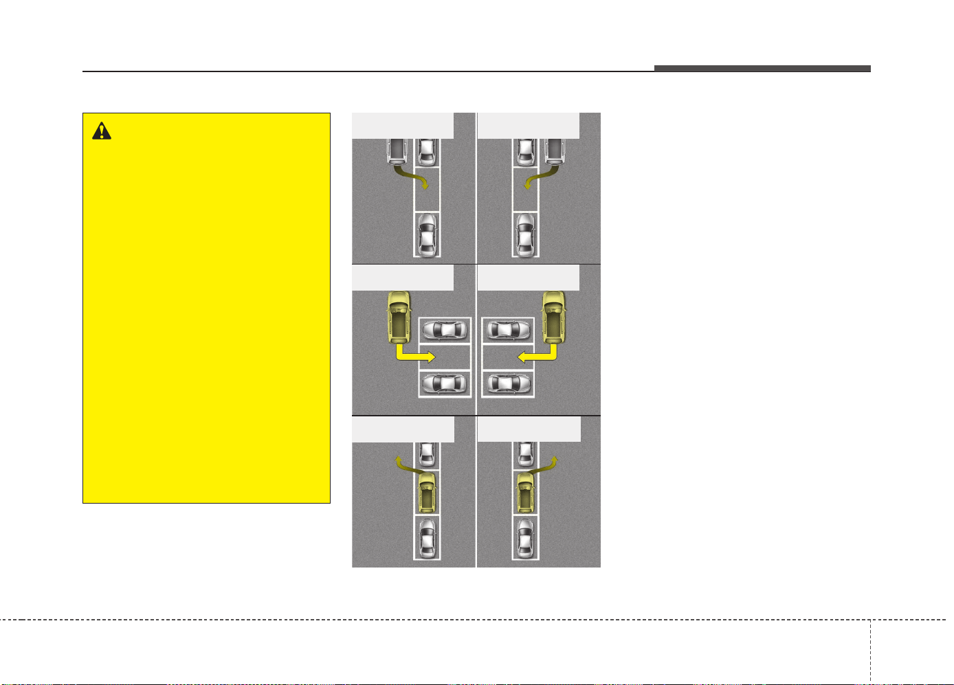
4105
Features of your vehicle
Operating condition
The system will help park the vehicle in
the middle or back of a parked vehicle.
Use the system when all the below con-
ditions are met.
• When the parking space is a straight
line
• When parallel parking or reverse (per-
pendicular) parking is required
• When there is a parked vehicle
• When there is enough space to move
the vehicle
WARNING
• The Smart Parking Assist System
should only be considered as a
supplementary function. The driv-
er must check the front and rear
view for objects. The operational
function of the Smart Parking
Assist System can be affected by
many factors and conditions of the
surroundings, so the responsibili-
ty rests always with the driver.
• The system may not operate nor-
mally if the vehicle needs wheel
alignment adjustment. Have the
vehicle checked by an authorized
Kia dealer.
• If you use a different tire or wheel
size rather than the size recom-
mended by the Kia dealer, the sys-
tem may not work properly. Always
use the same size tire and wheel.
• If you use additional frame on
license plate then SPAS may gen-
erate abnormal warning sound.
OLM041271
OPS043241
OPS043242
■ Right side
- Parallel parking
■ Left side
- Parallel parking
■ Right side
- Reverse parking
■ Left side
- Reverse parking
■ Left side
- Parallel exit
■ Right side
- Parallel exit
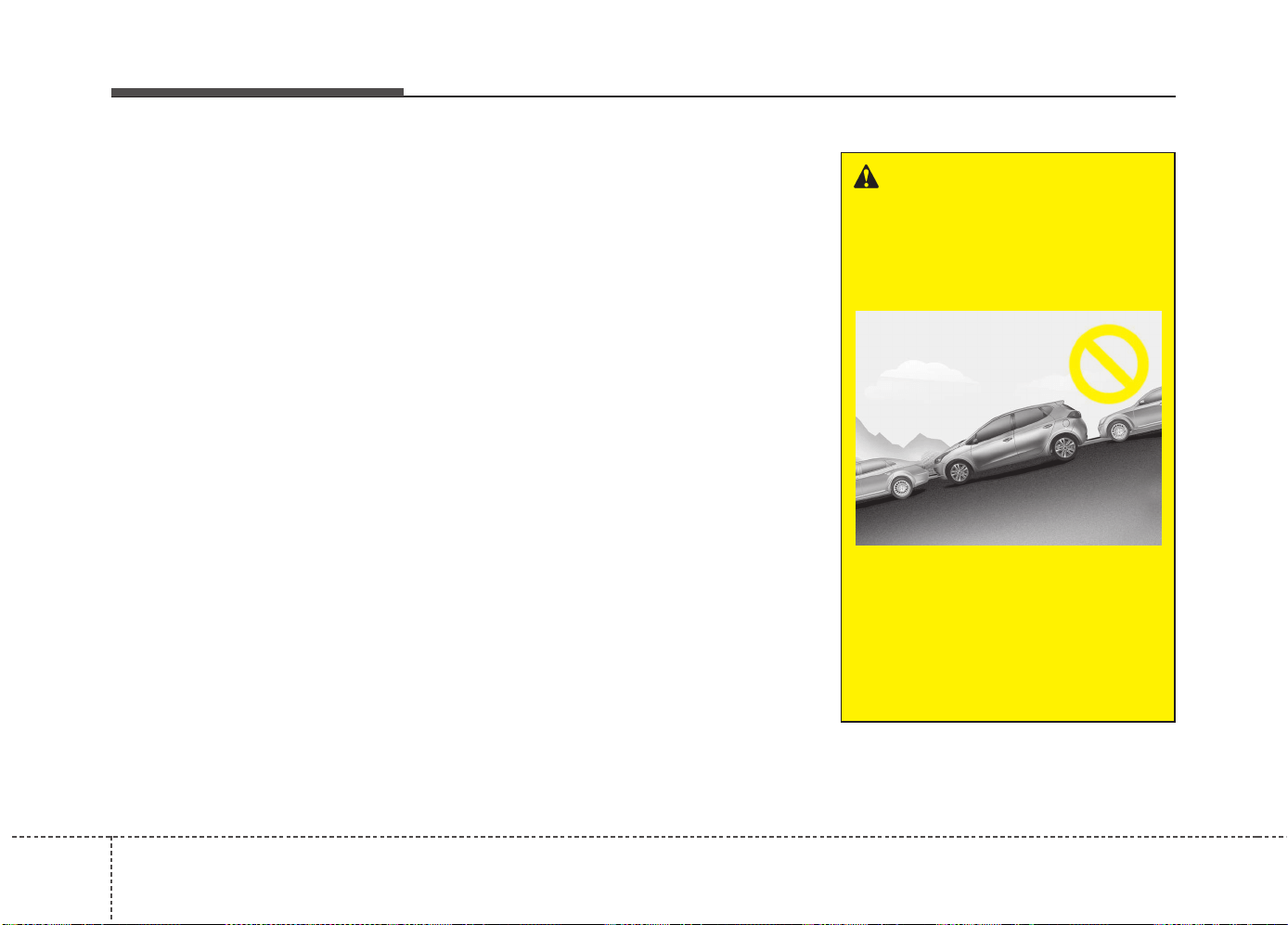
Features of your vehicle
1064
Non-operating condition
Never use the Smart Parking Assist
System in the below conditions.
• Curved parking space
• Inclined roads
• A vehicle loaded with longer or wider
cargo compared to the vehicle
• Diagonal parking space
• Parking space with trash, grass or bar-
riers
• Heavy snow or rain
• A pole close to the parking line
• Bumpy roads
• A vehicle equipped with a snow chain
or spare tire
• Tire pressure lower or higher than the
standard tire pressure
• A trailer connected to the vehicle
• Slippery or uneven road
• Big vehicles such as buses or trucks
parked
• Sensor covered with foreign matter,
such as snow or water
• Moisture frozen on the sensor.
• A motorcycle or bicycle parked
• A trash can or obstacle near
• Heavy wind
• Wheel changed to an unauthorized
size
• A problem with the wheel alignment
• Next to a garden or bush
• A accessory installed on the detective
area the of sensors (such as number
plate holder)
• Vehicle leaned severely to one side
• Strong sunlight or very cold weather
• Ultrasonic interference other vehicle's.
Such as horn sounds of other vehicles,
motorcycle's engine noise, air brake
noise of heavy vehicles and with the
other vehicle's parking assist system
working.
• Near a circular pillar or narrow pillar, or
a pillar surrounded by object such as
fire extinguisher, etc.
• The sensor is positioned incorrectly by
an impact to the bumper
WARNING
Do not use the Smart Parking
Assist System in the following con-
ditions for unexpected results may
occur and cause a serious accident.
1. Parking on inclines
The driver must apply the accelera-
tor and brake pedal when parking
on inclines. If the driver is unfamil-
iar with applying the accelerator
and brake pedal, a car accident may
occur.
(Continued)
OJD042156
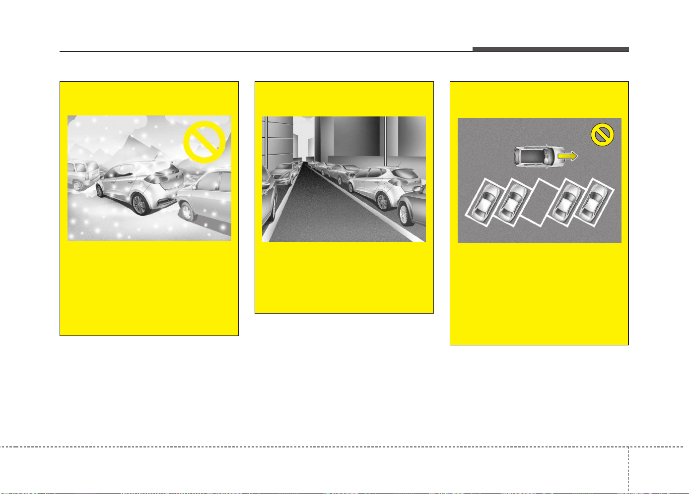
4107
Features of your vehicle
(Continued)
2. Parking in snow
Snow may interfere with sensor
operation or the system may cancel
if the road is slippery while parking.
Also, if the driver is unfamiliar with
applying the accelerator and brake
pedal, a car accident may occur.
(Continued)
(Continued)
3. Parking in narrow space
The system may not search for
parking spaces if the space is too
narrow. Even if it operates always
be careful.
(Continued)
OJD042157
OJD042158
(Continued)
4. Parking diagonal
The system is a supplemental for
parallel parking. Diagonal line park-
ing is not available. Even if the vehi-
cle is able to enter the space, do
not operate the Smart Parking
Assist System. The system will
attempt parallel parking.
(Continued)
OSL040145
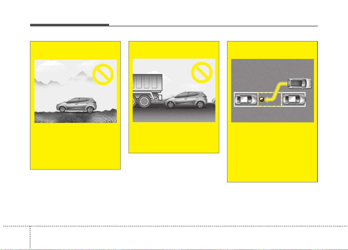
Features of your vehicle
1084
(Continued)
5. Parking in uneven road
Parking in uneven roads, the driver
needs to properly apply the pedal
(clutch, accelerator or brake). If not,
the system may cancel when the
vehicle slips or an accident may
occur.
(Continued)
(Continued)
6. Parking behind a truck
An accident may occur when park-
ing behind a vehicle higher than
yours. For example, bus, truck, etc.
(Continued)
OJD042159
OJD042160
(Continued)
7. Obstacle in parking space
The system may search for a park-
ing space even though an obstacle
is in the parking space. An accident
may occur if you continue to park
the vehicle with the system.
Do not solely rely on the Smart
Parking Assist System.
(Continued)
OLM041272
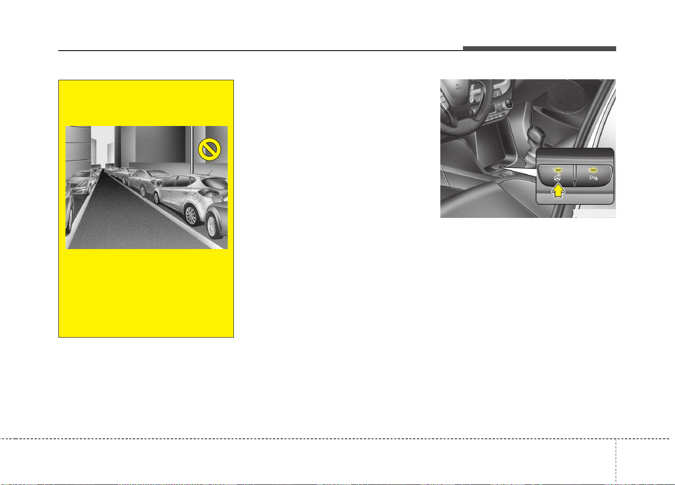
4109
Features of your vehicle
How the system works
(Parking mode)
1.Activate the Smart Parking Assist
System
The shift lever should be placed in D
(Drive) or N(Neutral).
2.Select parking assist mode
3.Search for parking space (slowly move
forward.)
4.Search complete (automatic search by
sensor.)
5.Steering wheel control
(1) Shift according to the instruction on
the LCD display.
(2) Drive slowly with the brake pedal
applied.
6.Smart Parking Assist System complete
7.If necessary, manually adjust position
of vehicle.
✽✽
NOTICE
• Before activating the system check if
the conditions are possible to use the
system.
• For your safety, always apply the
brake pedal except for when driving.
1. Activate Smart Parking Assist
System
• Press the Smart Parking Assist
System button (the button indicator will
illuminate).
• The Parking Assist System will be acti-
vated (the button indicator will illumi-
nate).
A warning sound will be heard if an
obstacle is detected.
• Press the Smart Parking Assist
System button again for more than 2
seconds to turn off the system.
• The Smart Parking Assist System
defaults to the OFF position whenever
the ignition switch is turned on.
OJD042082
(Continued)
8. Leaving a parking space near a
wall
When leaving a parking space that
is narrow and near a wall, the sys-
tem may not work properly. When
leaving a parking space similar to
the above picture, the driver must
watch out for obstacles while leav-
ing.
OJD045533
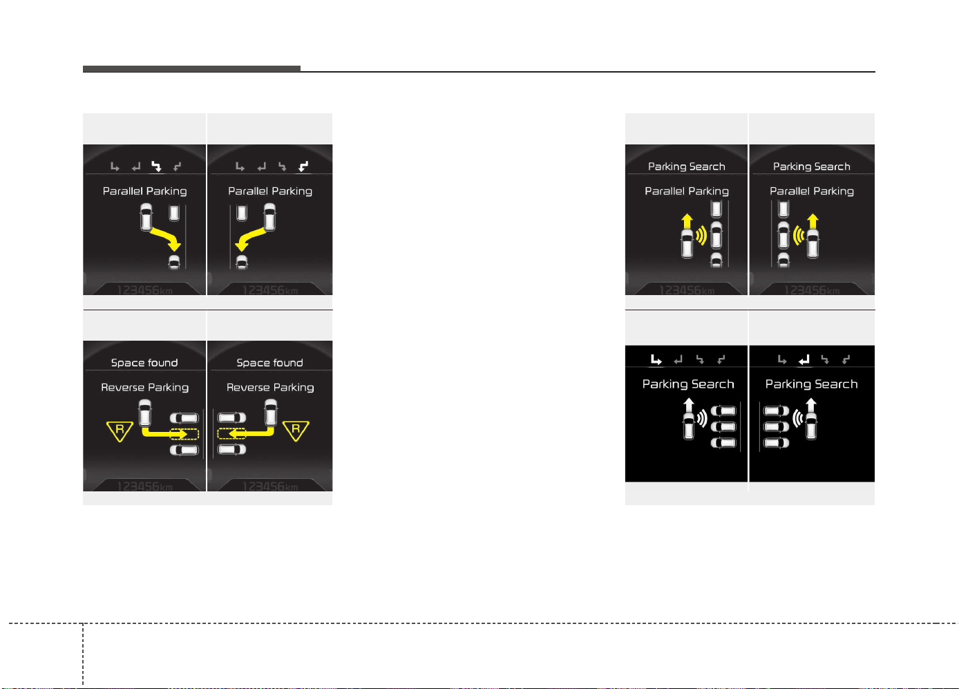
Features of your vehicle
1104
2. Select parking assist mode
• Select the parking assist mode by press-
ing the Smart Parking Assist System
button with the shift lever in N (Neutral)
or D(Drive) and the brake pedal
depressed. If the speed of the vehicle
has not exceeded 5km/h with the IGN in
ON, move the shift lever to N(Neutral) to
select the parallel exit mode.
• The right side parallel mode is select-
ed automatically when the Smart
Parking Assist System is activated.
• To select the left side parallel mode
press the Smart Parking Assist System
button once more.
• If the button is pressed again, the sys-
tem will turn off.
• The mode changes from parallel mode
(right → left) to reverse mode (right →
left) whenever the Smart Parking Assist
System button is pressed. (for LHD)
• The mode changes from parallel mode
(left → right) to reverse mode (left →
right) whenever the Smart Parking
Assist System button is pressed. (for
RHD)
3. Search for parking space (optional)
• Slowly drive forward maintaining the
distance of approximately 50cm ~
150cm (19.6in.~59.0in.) with the
parked vehicles. The side sensors will
search for a parking space.
■ Right side
- parallel mode
■ Left side
-parallel mode
■ Right side
- reverse mode
■ Left side
- reverse mode
OJD045306L/OJD045307L
OUM044308L/OUM044309L
■ Right side
- parallel mode
■ Left side
-parallel mode
■ Right side
- reverse mode
■ Left side
- reverse mode
OJD045536L/OJD045537L
OJD045304L/OJD045305L
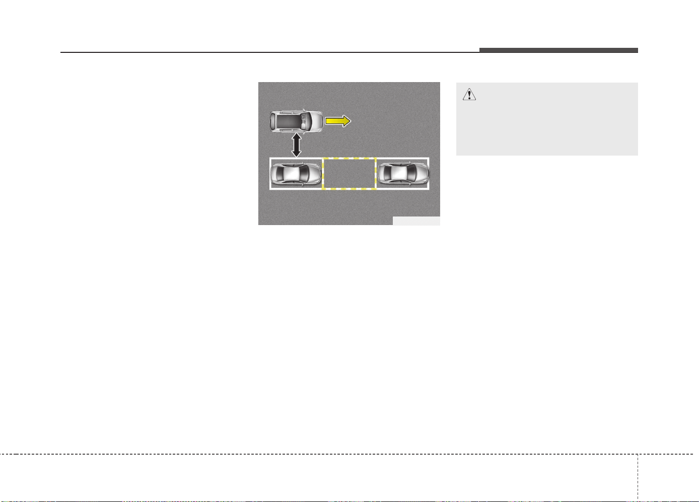
4111
Features of your vehicle
• If the vehicle speed is over 20km/h
(12.4mph), a message will appear to
notify to reduce speed.
• If the vehicle speed is over 30km/h
(18.6mph), the system will cancel.
✽✽
NOTICE
• Turn on the hazard warning flasher if
it is crowded with other vehicles.
• If the parking lot is small, slowly drive
more nearer to the parking space.
• The search for a parking space will be
completed only when there is enough
space for the vehicle to move to park.
✽
✽
NOTICE
• When searching for a parking space,
the system may not be able to find a
parking space if there is no vehicle
parked, a parking space is available
after driving by or a parking space is
available before driving by.
• The system may not operate normally
in the following conditions:
(1) When the sensors are frozen
(2) When the sensors are dirty
(3) When it snows or rains heavily
(4) When a pillar or object is near
✽
✽
NOTICE
Slowly drive forward maintaining the
distance of approximately 50cm ~
150cm (19.6in.~59.0in.) with the parked
vehicles. If not within the distance, the
system may not be able to search for a
parking space.
CAUTION
After searching for a parking space
is completed, continue using the
system after checking the sur-
rounding area.
OLM041273
50~150 cm
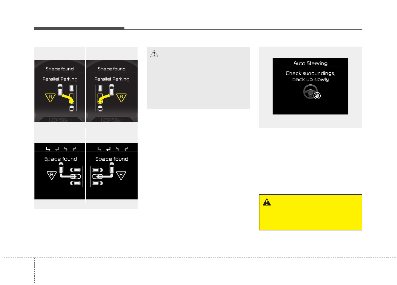
Features of your vehicle
1124
4. Search complete
While driving forward to search for a
parking space, the above message will
appear with a beep sound if the search is
complete. Stop the vehicle and shift to
the R (Reverse) position.
5. Steering wheel control
• The above message will appear if the
shift lever is in R (Reverse). The steering
wheel will be controlled automatically.
• The system will be cancelled if you
firmly hold the steering wheel while it is
controlled automatically.
• The system will be cancelled if vehicle
speed is over 7km/h(4.3mph).
CAUTION
• Always drive slowly with the
brake pedal applied.
• If the parking space is to small
the system may be cancelled at
the Steering wheel control stage.
Do not park your vehicle if the
space is too small.
OUM044315L
WARNING
Do not put your hands between the
steering wheel while it is being
automatically controlled.
■ Right side
- parallel mode
■ Left side
-parallel mode
■ Right side
- reverse mode
■ Left side
- reverse mode
OJD045302L/OJD045303L
OUM044304L/OUM044305L
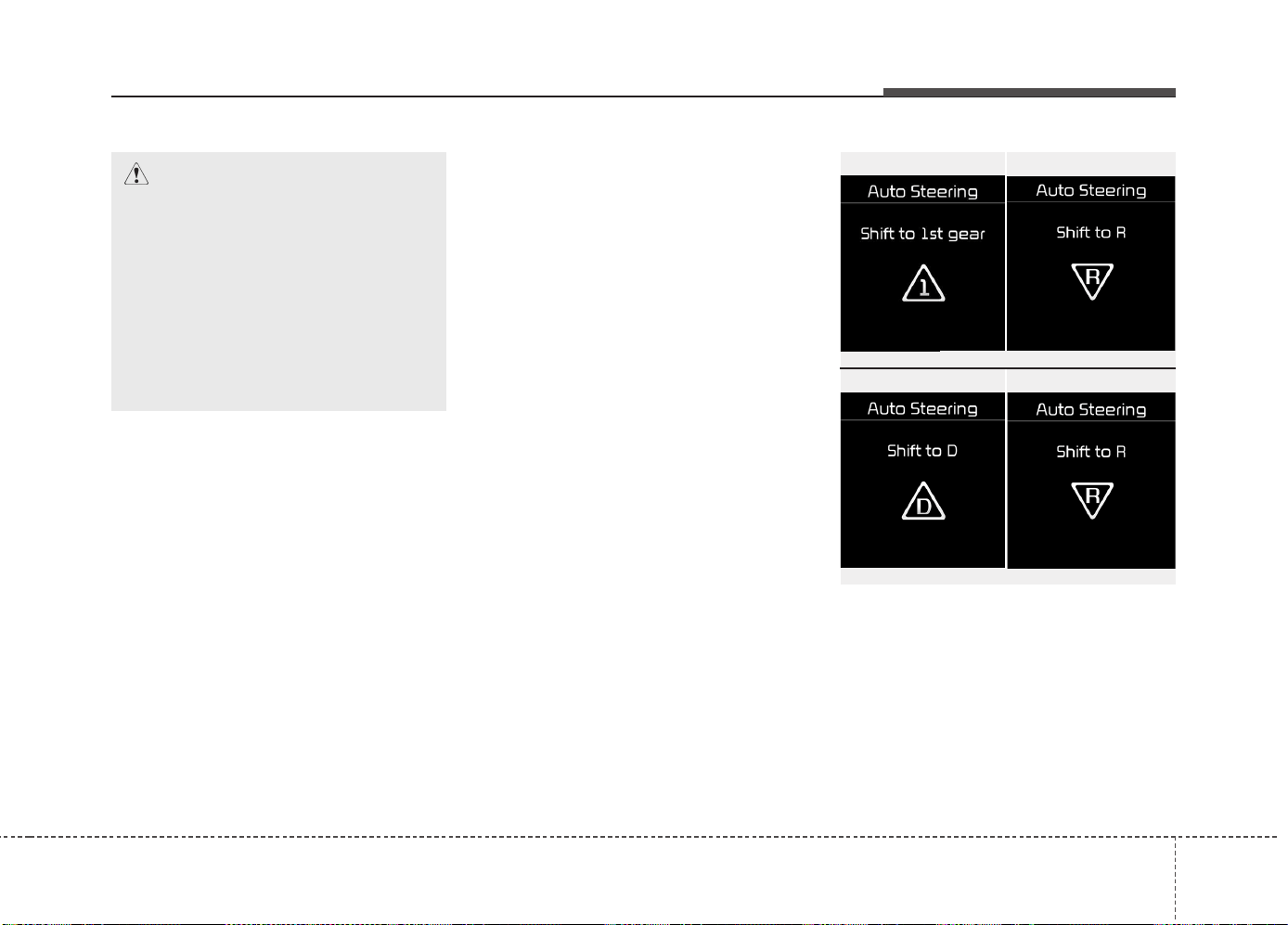
4113
Features of your vehicle
✽✽
NOTICE
• If you do not follow the instructions pro-
vided, you may fail to park your vehicle.
However, if the Parking Assist System
warning sound (distance from object
is within 30cm: continuous beep)
occurs, slowly drive the vehicle to the
reverse direction of the detected
object after checking the surrounding.
• Always check the surrounding before
driving your vehicle if the Parking
Assist System warning sound (dis-
tance from object is within 30cm: con-
tinuous beep) is heard for the object is
close to your vehicle.
To cancel the system while parking
Press the Smart Parking Assist System
button or turn the steering wheel to the
left or right.
Gear shift while steering wheel control
When the above message appears with a
beep sound, shift the gear and drive the
vehicle with the brake pedal depressed.
■ Manual transaxle
■ Automatic transaxle
OUM044316L/OUM044317L
OUM044318L/OUM044317L
CAUTION
• Always drive slowly with the
brake pedal applied.
• Always check for objects around
your vehicle before driving.
• If the vehicle does not move even
though the brake pedal is not
depressed, check the surround-
ing before depressing the accel-
erator pedal. Be sure not to speed
over 7km/h(4.3mph).
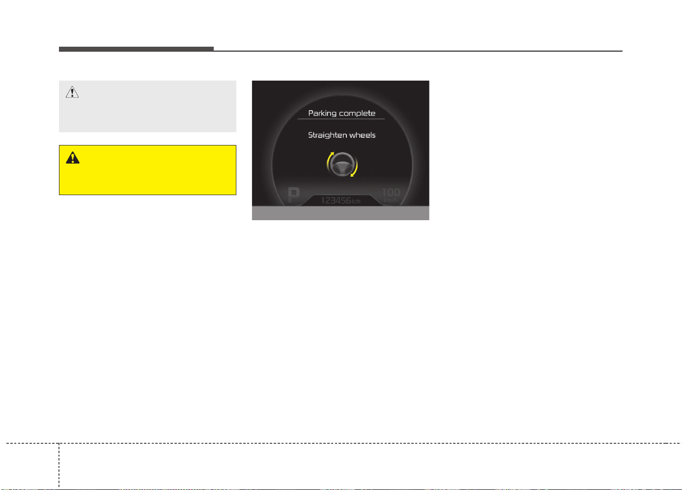
Features of your vehicle
1144
6. Smart Parking Assist System com-
pleted
Complete parking your vehicle according
to the instructions on the LCD display. If
required, manually control the steering
wheel and complete parking your vehicle.
✽✽
NOTICE
The brake pedal must be depressed by
the driver while parking your vehicle.
The system may be cancelled in the below
conditions:
• Ignoring the gear shift message and
drive the vehicle approximately 150cm
(59in).
• The front and rear Parking Assist
System warning sound (distance from
object is within 30cm: continuous
beep) is heard at the same time.
• 6 minutes have passed since the vehi-
cle has been controlled by the Smart
Parking Assist System.
• The shift lever is changed to the P
(Park) or R (Reverse) position while
searching for parking space.
OJD045531L
WARNING
Always be careful while parking for
other vehicles or pedestrians.
CAUTION
Always check the surrounding
before releasing the brake pedal.
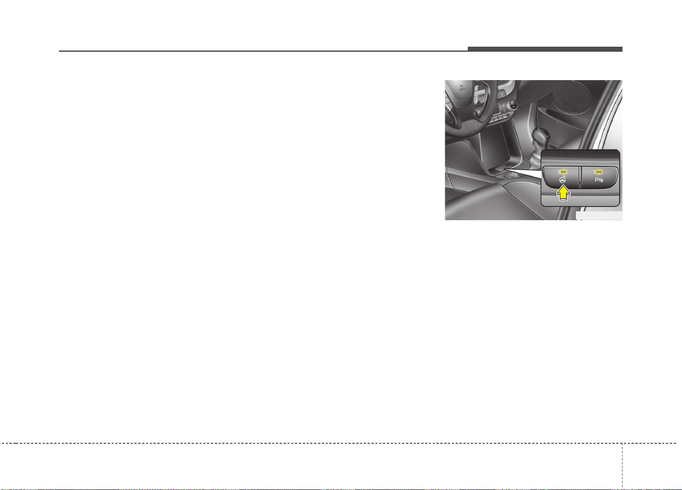
4115
Features of your vehicle
How the system works
(Exit mode)
The Exit Mode operates in the below
condition:
• When vehicle speed is below 5 km/h
the first time after the engine has been
started.
• After parallel parking is completed with
the Smart Parking Assist System.
1. Activate the Smart Parking Assist
System
The shift lever should be placed in P
(Park) or N (Neutral).
2. Select Exit Mode
3. Check surroundings
4. Steering wheel control
(1) Shift according to the instruction
on the LCD display.
(2) Drive slowly with the brake pedal
applied.
5. Exiting complete
If necessary, manually adjust position
of vehicle.
✽✽
NOTICE
• Before activating the system check if
the conditions are possible to use the
system.
• For your safety, always apply the
brake pedal except for when driving.
1. Activate Smart Parking Assist
System
• Press the Smart Parking Assist
System button (the button indicator will
illuminate).
• The Parking Assist System will be acti-
vated (the button indicator will illumi-
nate).
A warning sound will be heard if an
obstacle is detected.
• Press the Smart Parking Assist
System button again for more than 2
seconds to turn off the system.
• The Smart Parking Assist System
defaults to the OFF position whenever
the ignition switch is turned on.
OJD042082
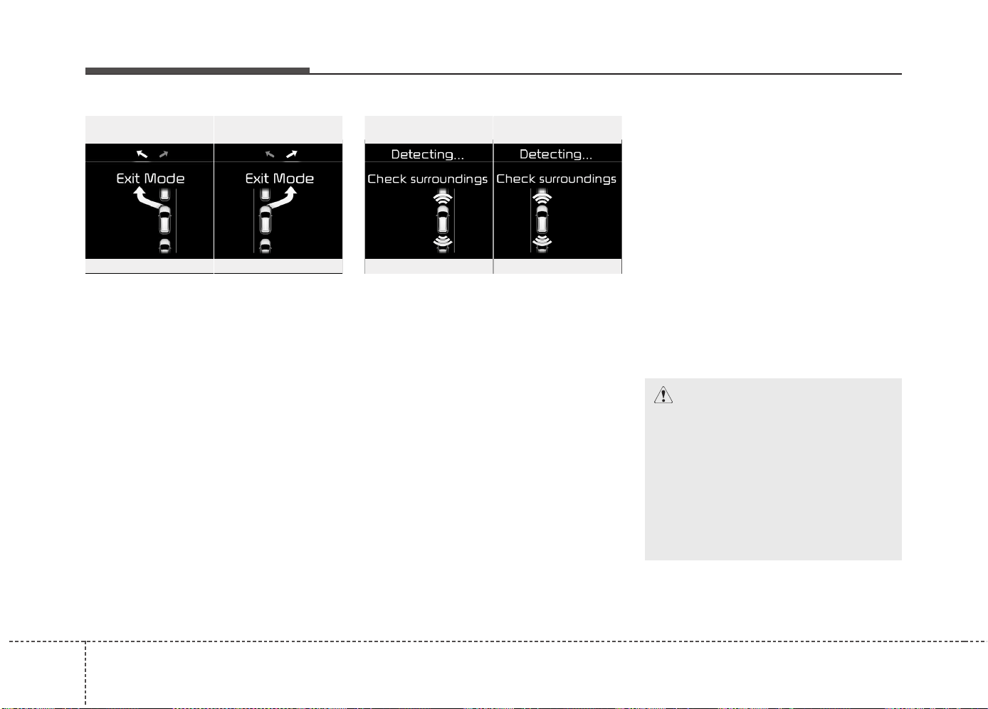
Features of your vehicle
1164
2. Select Exit Mode
• Select the mode by pressing the Smart
Parking Assist System button with the
shift lever in P (Park) or N (Neutral)
and the brake pedal depressed.
• The left side parallel mode is selected
automatically when the Smart Parking
Assist System is activated.
• To select the right side parallel mode
press the Smart Parking Assist System
button once more.
• If the button is pressed again, the sys-
tem will turn off.
3. Check surroundings
The Smart Parking Assist System checks
the front and rear space to exit the vehicle
from the parking space.
✽✽
NOTICE
• When checking surroundings, if the
front or rear vehicle (or object) is too
near, the system may not work prop-
erly.
• The system may not operate normally
in the following conditions:
(1) When the sensors are frozen
(2) When the sensors are dirty
(3) When it snows or rains heavily
(4) When a pillar or object is near
• When exiting the parking space if an
obstacle is detected that may cause an
accident, the system may cancel.
• If the space is too small to exit the sys-
tem may cancel.
OUM044326LOUM044325L
■ Left side
- Parallel exit
■ Right side
- Parallel exit
CAUTION
• If searching surroundings is com-
pleted, continue using the system
after checking the surrounding
area.
• The Exit mode may be activated
unintentionally, when the shift
lever is in P (Park) or N (Neutral) if
the Smart parking assist system
button is pressed.
OUM044324L
OUM044323L
■ Left side
- Parallel exit
■ Right side
- Parallel exit
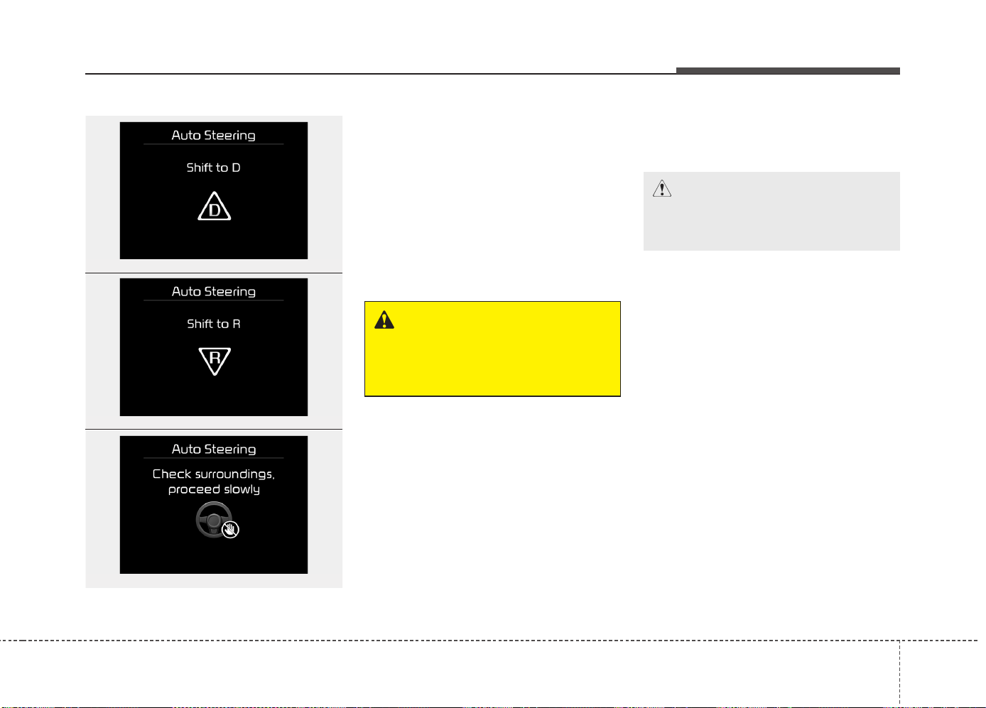
4117
Features of your vehicle
4. Steering wheel control
• The above message will appear if the
shift lever is in D (Drive) or R (Reverse)
according to the distance of the front
and rear object from the sensor.
The steering wheel will be controlled
automatically.
• The system will be cancelled if you
firmly hold the steering wheel while it is
controlled automatically.
• The system will be cancelled if vehicle
speed is over 7km/h (4.3mph).
To cancel the system while exiting
Press the Parking Assist System or
Smart Parking Assist System button.
WARNING
Do not put your hands between the
steering wheel while it is being
automatically controlled.
CAUTION
Always drive slowly with the brake
pedal applied.
OUM044318L
OUM044317L
OUM045315L
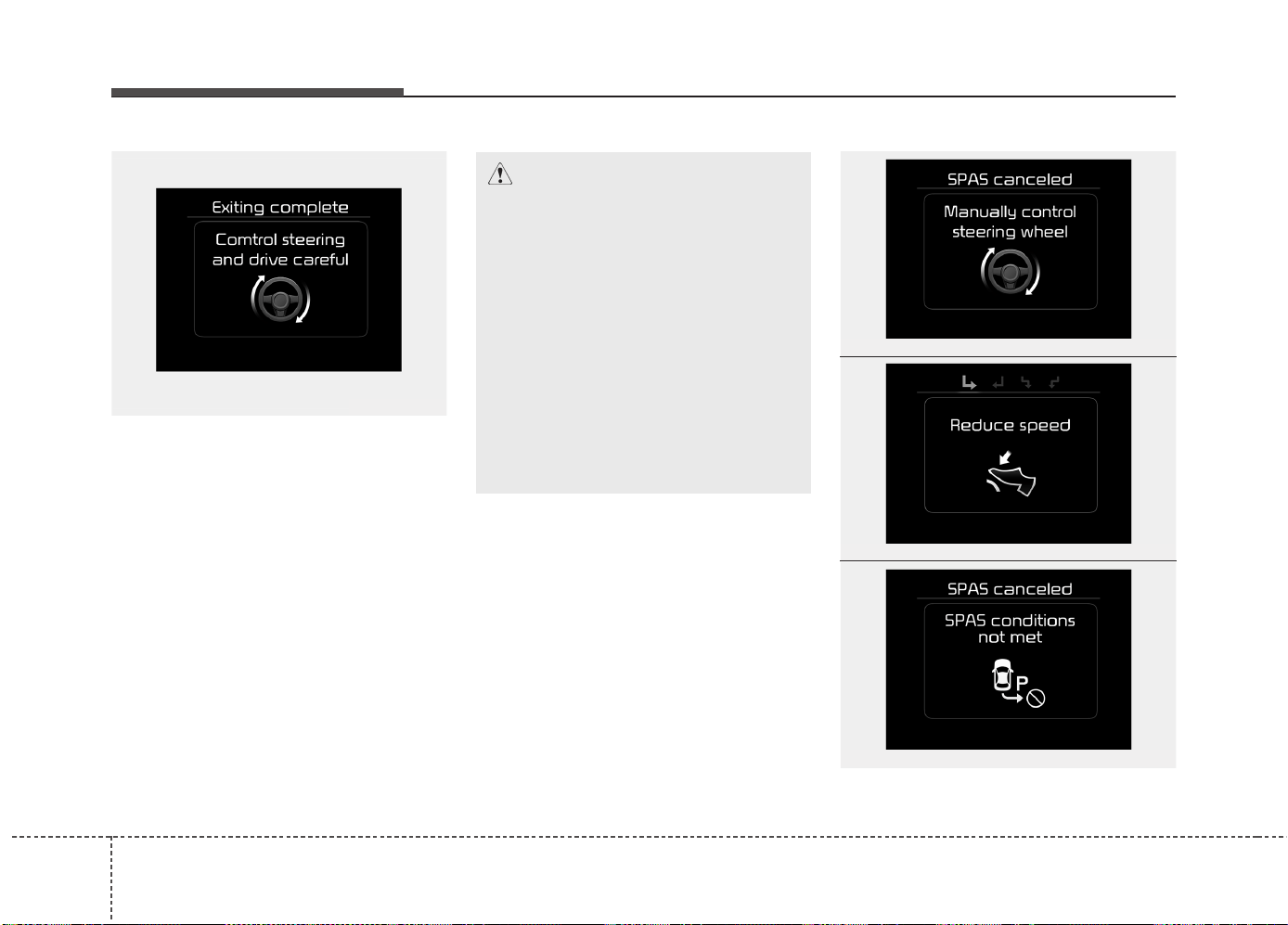
Features of your vehicle
1184
5. Exiting Complete
When assisting the driver exit the parking
space is completed the above message
will appear.
Turn the steering wheel to the direction
you are leaving and manually control the
steering wheel while leaving the parking
space.
Additional instructions(messages)
CAUTION
• When leaving the parking space
turn the steering wheel as much
as you can to the direction you
are leaving, and then drive the
vehicle slowly by depressing the
vehicle.
• Always check the surrounding
before driving your vehicle if the
Parking Assist System warning
sound is continuously heard.
• The system will be cancelled for
safety reasons if the vehicle is
parked at a small space near a
wall.
OUM044328L
OUM044319L
OUM044320L
OUM044321L
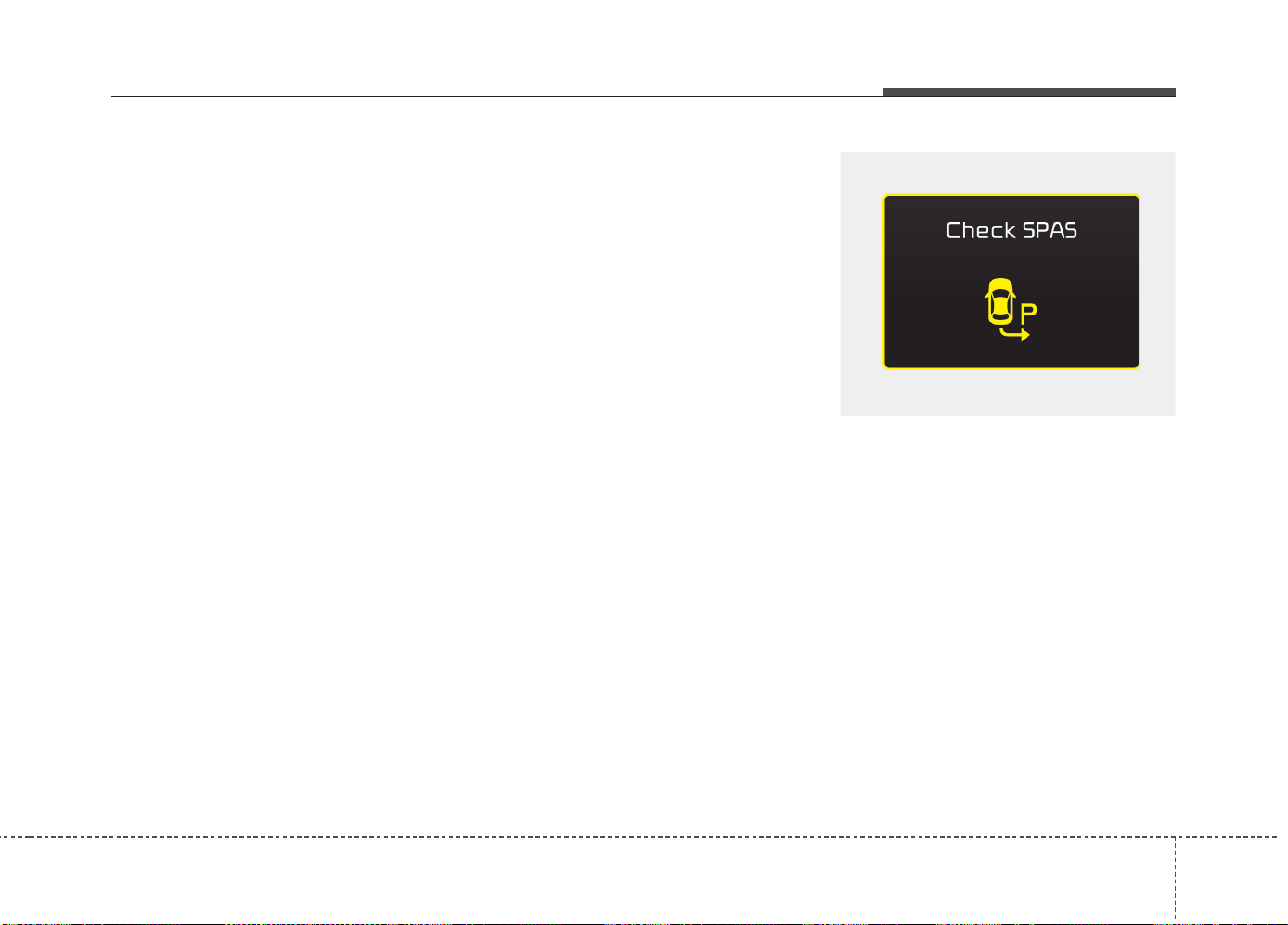
4119
Features of your vehicle
When the Smart Parking Assist System
is operating, a message may appear
regardless of the parking order.
The messages will appear according to
the circumstances. Follow the instruc-
tions provided while parking your vehicle
with the Smart Parking Assist System.
✽✽
NOTICE
• In the below conditions the system will be
cancelled. Park your vehicle manually.
1. Search for parking space
- When the ABS/ESC is activated
- When the vehicle speed is over
30km/h(18.6mph)
- When you press the Smart Parking
Assist System button (the front and
rear Parking Assist System operates)
- When you shift the shift lever to R
(Reverse)
2. Steering wheel control
- When the ABS/ESC is activated
- When the vehicle speed is over
7km/h (4.3 mph)
- When you press the Smart Parking
Assist System button (the front and
rear Parking Assist System operates)
- When you shift the shift lever to D
(Drive) before entering the parking
space
- When you hold the steering wheel
firmly
System malfunction
• If there is a problem with the system,
when the system is turned on, the
above message will appear. Also, the
indicator on the button will not light up
and a beep sound will be heard 3 times.
• If there is a problem with only the
Smart Parking Assist System, the
Parking Assist System will operate
after 2 seconds.
If you notice any problem, have your
vehicle checked by an authorized Kia
dealer as soon as possible.
OJD045532L
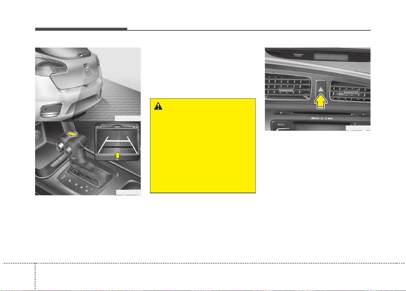
Features of your vehicle
1204
REARVIEW CAMERA (IF EQUIPPED)
❈ The actual rear view in the vehicle may dif-
fer from the illustration.
The rearview camera will activate when
the back-up light is ON with the ignition
switch ON and the shift lever in the R
(Reverse) position.
This system is a supplemental system
that shows behind the vehicle through
the navigation monitor while backing-up.
❈ For more detailed informations, refer
to supplement for navigation system.
The hazard warning flasher should be
used whenever you find it necessary to
stop the vehicle in a hazardous location.
When you must make such an emer-
gency stop, always pull off the road as far
as possible.
The hazard warning lights are turned on
by pushing in the hazard switch. Both
turn signal lights will blink. The hazard
warning lights will operate even though
the key is not in the ignition switch.
To turn the hazard warning lights off,
push the switch again.
OJD042089
HAZARD WARNING FLASHER
WARNING
• This system is a supplementary
function only. It is the responsibil-
ity of the driver to always check
the inside/outside rearview mirror
and the area behind the vehicle
before and while backing up
because there is a dead zone that
can't see through the camera.
• Always keep the camera lens
clean. If lens is covered with for-
eign matter, the camera may not
operate normally.
OJD045086
OJD042088
RR
RR
ee
ee
aa
aa
rr
rr
vv
vv
ii
ii
ee
ee
ww
ww
dd
dd
ii
ii
ss
ss
pp
pp
ll
ll
aa
aa
yy
yy

4121
Features of your vehicle
Battery saver function
• The purpose of this feature is to pre-
vent the battery from being dis-
charged. The system automatically
turns off the parking lights when the
driver removes the ignition key (Smart
key : turns off the engine) and opens
the driver- side door.
• With this feature, the parking lights will
be turned off automatically if the driver
parks on the side of road at night.
If necessary, to keep the lights on
when the ignition key is removed, per-
form the following :
1) Open the driver-side door.
2) Turn the parking lights OFF and ON
again using the light switch on the
steering column.
Headlamp delay function
(if equipped)
The headlamps (and/or taillights) remain
on for same minutes (Type A: 20 minutes,
Type B: 5 minutes) after the ignition key
is removed or turned to the ACC or
LOCK position. However, if the driver’s
door is opened and closed, the head-
lights are turned off after 15 seconds.
The headlights can be turned off by
pressing the lock button on the transmit-
ter or smart key twice or turning off the
light switch from the headlight or Auto
light position.
You can activate or deactivate the head-
lamp delay fuction. Refer to “User setting”
in this chapter.
Headlight (Headlamp) welcome
function (if equipped)
When the headlight switch is in the ON or
AUTO position and all doors (and tail-
gate) are closed and locked, if you press
the door unlock button on the transmitter
or smart key, the headlights will come on
for about 15 seconds.
If the headlight switch is in the AUTO
position, the function can only operate at
night.
At this time, if you press the door unlock
button again or door lock button on the
transmitter or smart key, the headlights
will turn off immediately.
You can activate or deactivate the head-
lamp welcome fuction. Refer to “User set-
ting” in this chapter.
✽✽
NOTICE
There can be turned on front fog light
and the fail light when you turn on the
headlight switch ON. In this case we rec-
ommend that you the system checked by
an authorized Kia dealer.
LIGHTING
CAUTION
If the driver gets out of the vehicle
through other doors (except driver’s
door), the battery saver function
does not operate and the headlamp
delay function does not turn off
automatically. Therefore, it causes
the battery to be discharged. In this
case, make sure to turn off the lamp
before getting out of the vehicle.
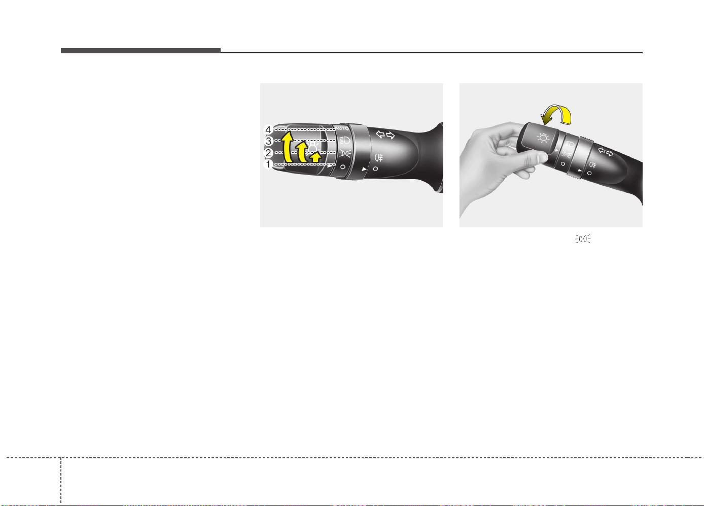
Features of your vehicle
1224
Static bending light (if equipped)
While driving the corner, for your sight
and safety, the static bending light turns
on automatically. The system will operate
automatically as follows:
• When vehicle speed is under 10km/h
and steering wheel angle approximate-
ly 80 degrees.
• When vehicle speed is over 10km/h
and steering wheel angle approximate-
ly 35 degrees.
• When the vehicle is at a standstill.
• When moving rearwards with one of
the above conditions satisfied the lights
will light up the opposite direction.
Lighting control
The light switch has a Headlight and a
Parking light position.
To operate the lights, turn the knob at the
end of the control lever to one of the fol-
lowing positions:
(1) OFF position
(2) Position light position
(3) Headlight position
(4) Auto light position (if equipped)
Position light position ( )
When the light switch is in the position
light position, the tail, position, license
and instrument panel lights are ON.
OED040045 OED040046
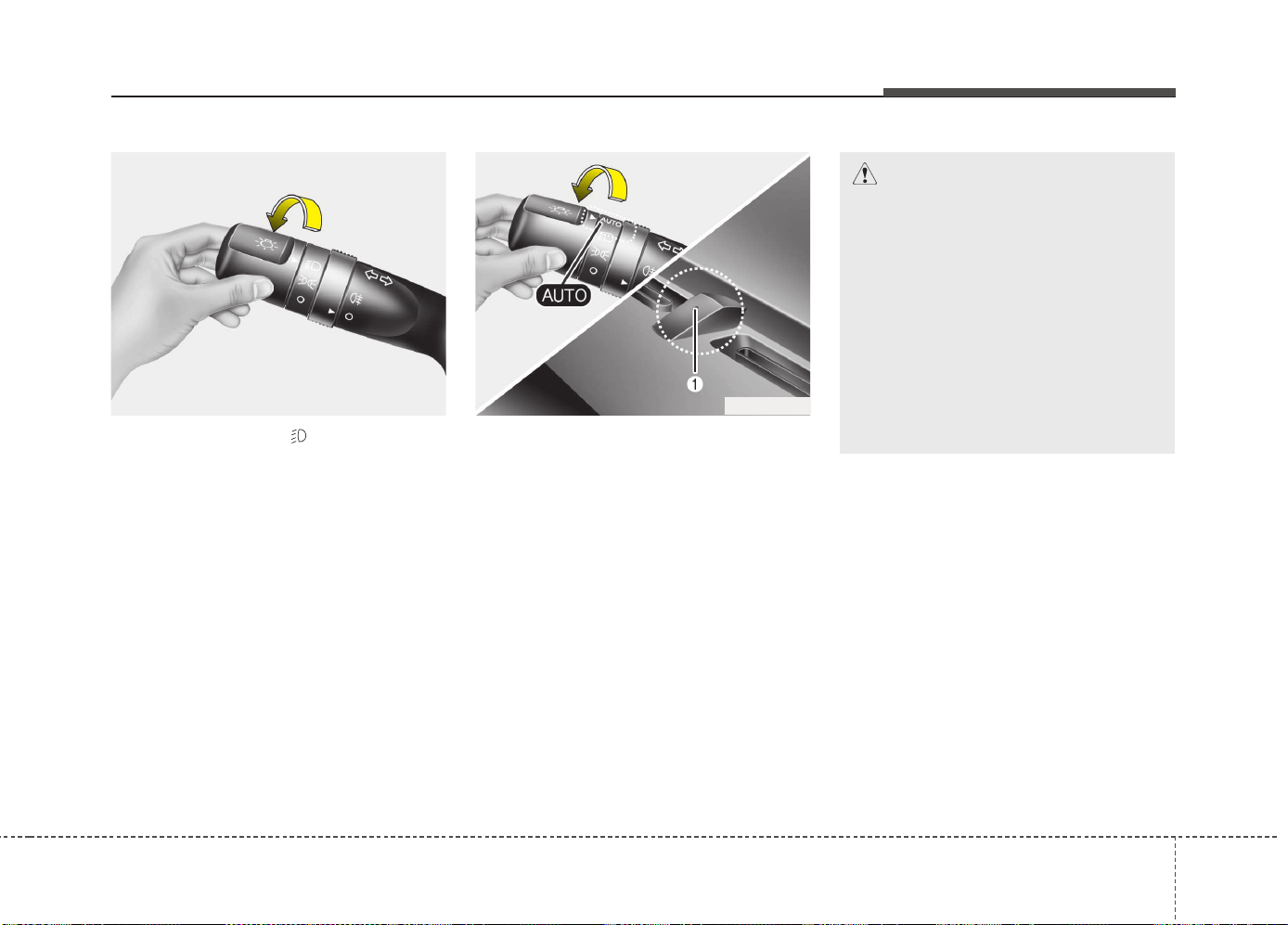
4123
Features of your vehicle
Headlight position ( )
When the light switch is in the headlight
position the head, tail, position, license
and instrument panel lights are ON.
✽✽
NOTICE
The ignition switch must be in the ON
position to turn on the headlights.
Auto light/AFLS position
(if equipped)
When the light switch is in the AUTO light
position, the taillights and headlights will
be turned ON or OFF automatically
depending on the amount of light outside
the vehicle.
If your vehicle is equipped with the adap-
tive front lighting system (AFLS), it will
also operate when the headlamp is ON.
OYN049201
CAUTION
• Never place anything over the
sensor (1) located on the instru-
ment panel, this will ensure better
auto-light system control.
• Do not clean the sensor using a
window cleaner, the cleaner may
leave a light film which could
interfere with sensor operation.
• If your vehicle has window tint or
other types of coating on the
front windshield, the Auto light
system may not work properly.
OED040800
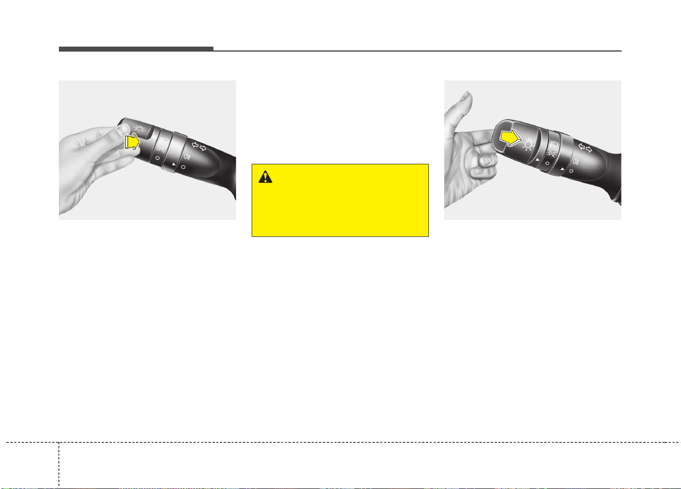
Features of your vehicle
1244
High - beam operation
1. Turn the light switch to the headlight
position.
2. Push the lever away from you.
• The high-beam indicator will light when
the headlight high beams are switched
on.
• To prevent the battery from being dis-
charged, do not leave the lights on for
a prolonged time while the engine is
not running.
Flashing headlights
Pull the lever towards you. It will return to
the normal position when released. The
headlight switch does not need to be on
to use this flashing feature.
WARNING
Do not use high beam when there
are other vehicles. Using high
beam could obstruct the other dri-
ver's vision.
OED040801
OED040802
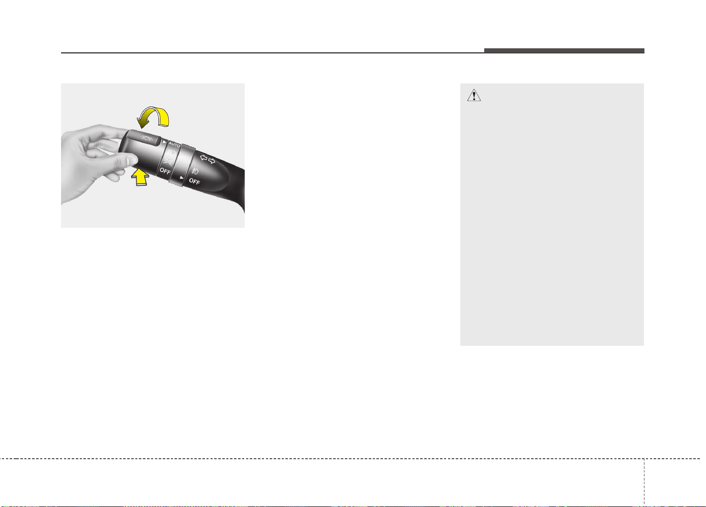
4125
Features of your vehicle
High Beam Assist (HBA)
(if equipped)
The high beam assist is a system that
automatically adjusts headlamp range
(switches between high beam and low
beam) according to the brightness of
other vehicles and road conditions.
Operating condition
1.Place the light switch in the AUTO
position.
2.Turn on the high beam by pushing the
lever away from you.
The high beam assist indicator will illu-
minate.
3.The High Beam Assist will turn on
when vehicle speed is above 45km/h.
4.If the light switch is placed to the head-
light position, the high beam assist will
turn off and the low beam will be on
constantly.
The high beam switches to low beam in
the below conditions.
- When headlight is detected from on-
coming vehicle
- When tail light is detected from the
front vehicle.
- When streetlight or other light is
detected.
- When the high beam assist turns off
- When vehicle speed is below 35km/h
OPS043238
CAUTION
The system may not operate normal-
ly in the below conditions.
• When the light from on-coming or
front vehicle is not detected
because of lamp damage, hidden,
etc.
• When the lamp of the on-coming
or front vehicle is covered with
dust, snow or water.
• When the light from on-coming or
front vehicle is not detected
because of exhaust fume, smoke,
fog, snow, etc.
• When the front window is covered
with foreign matters such as ice,
dust, fog, or is damaged.
• When there is a similar lamp with
the front vehicle’s lamps
• When it is hard to see because of
fog, heavy rain or snow.
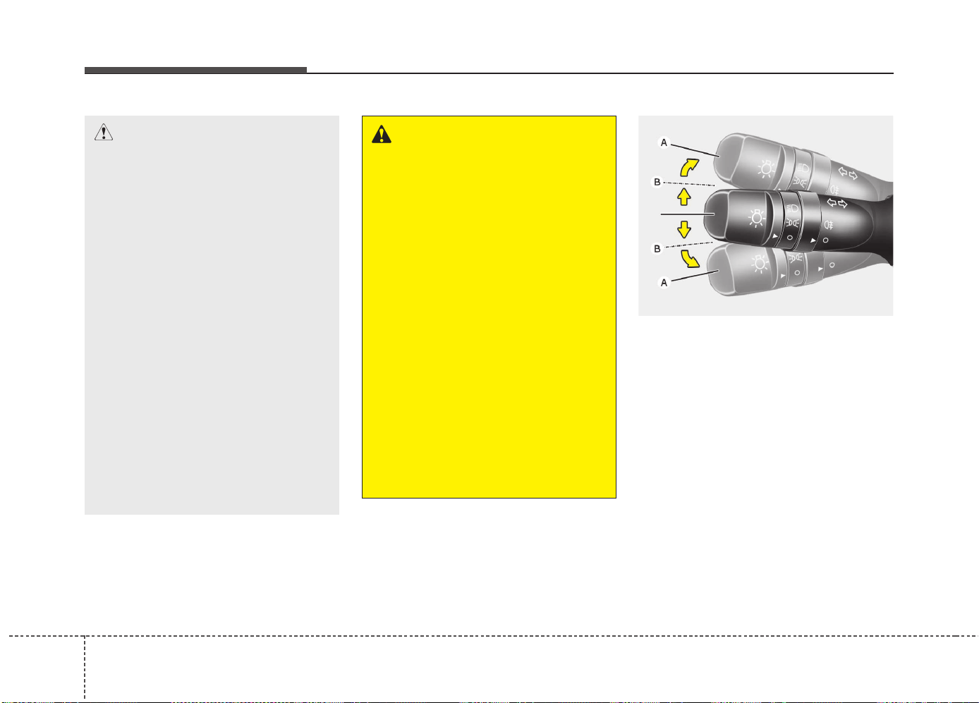
Features of your vehicle
1264
Turn signals and lane change sig-
nals
The ignition switch must be on for the
turn signals to function. To turn on the
turn signals, move the lever up or down
(A). Green arrow indicators on the instru-
ment panel indicate which turn signal is
operating.
They will self-cancel after a turn is com-
pleted. If the indicator continues to flash
after a turn, manually return the lever to
the OFF position.
To signal a lane change, move the turn
signal lever slightly and hold it in position
(B). The lever will return to the OFF posi-
tion when released.
OED040804
WARNING
• Do not place any accessories,
stickers or tint the windshield.
• Have the windshield glass
replaced from an authorized deal-
er.
• Do not remove or impact related
parts of the high beam assist.
• Be careful that water doesn’t get
into the high beam assist unit.
• Do not place objects on the dash-
board that reflects light such as
mirrors, white paper, etc. The sys-
tem may malfunction if the sun-
light is reflected.
• At times, the high beam assist
system may not work properly,
always check the road conditions
for your safety. When the system
does not operate normally, manu-
ally change the high beam and
low beam.
CAUTION
• When the headlamp is not
repaired or replaced at an author-
ized dealer.
• When the headlamp aiming is not
properly adjusted.
• When driving on a narrow curved
road or rough road.
• When driving downhill or uphill.
• When part of the vehicle in front
is visible.
• When there is a traffic light,
reflecting sign, flash sign or mir-
ror.
• When the road conditions are bad
such as being wet or covered
with snow.
• When the front vehicle’s head-
lights are off but the fog lights on.
• When a suddenly appears from a
curve.
• When the vehicle is tilted from a
flat tire or being towed.
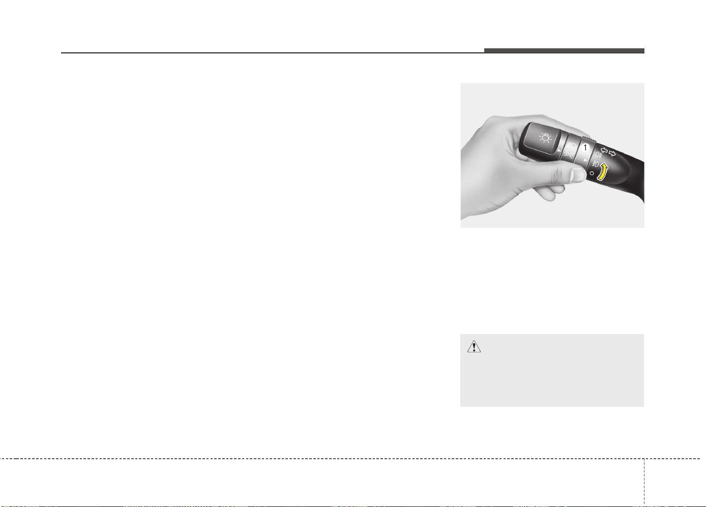
4127
Features of your vehicle
If an indicator stays on and does not
flash or if it flashes abnormally, one of the
turn signal bulbs may be burned out and
will require replacement.
One-touch lane change function
(if equipped)
To activate an one-touch lane change
function, move the turn signal lever
slightly and then release it. The lane
change signals will blink 3 times.
You can inactivate one-touch lane change
function in “Auto triple turn” of “User set-
ting”. Refer to “User setting” in chapter 4.
✽✽
NOTICE
If an indicator flash is abnormally quick
or slow, bulb may be burned out or have
a poor electrical connection in the circuit.
Front fog light (if equipped)
Fog lights are used to provide improved
visibility when visibility is poor due to fog,
rain or snow, etc. The fog lights will turn
on when the fog light switch (1) is turned
on after the position light is turned on.
To turn off the fog lights, turn the fog light
switch (1) to the O (Off) position.
OYN049200
CAUTION
When in operation, the fog lights
consume large amounts of vehicle
electrical power. Only use the fog
lights when visibility is poor.
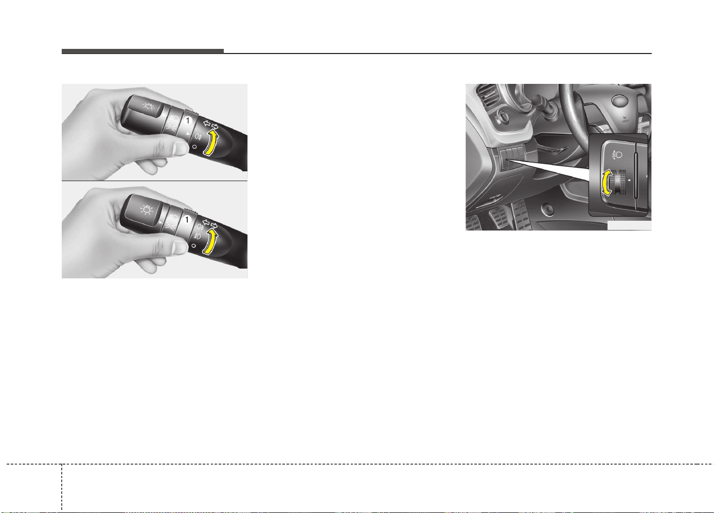
Features of your vehicle
1284
Rear fog light
To turn the rear fog lights on, turn the
rear fog light switch (1) to the on position
when the headlight is turned on.
Also, the rear fog lights turn on when the
rear fog light switch is turned on after the
front fog light switch (if equipped) is
turned on and the headlight switch is in
the position light position.
To turn the rear fog lights off, turn the rear
fog light switch to the on position again.
Rear fog light is located only on the dri-
ver’s side (for wagon).
Daytime running light
(if equipped)
Daytime Running Lights (DRL) can make
it easier for others to see the front of your
vehicle during the day. DRL can be help-
ful in many different driving conditions,
and it is especially helpful after dawn and
before sunset.
The DRL system will turn off when:
Type A
• When headlight (Low beam) switch is
ON, DRL-LED system will be illuminat-
ing with lower intensity
• The front fog light switch is ON.
• The engine is OFF.
Type B
• The headlight (low beam) switch is ON.
• The front fog light switch is ON.
• The engine is OFF.
Headlight leveling device
(if equipped)
Manual type
To adjust the headlight beam level
according to the number of the passen-
gers and the loading weight in the lug-
gage area, turn the beam leveling switch.
OJD042049
OED040806
OAM049046L
■ Type A
■ Type B
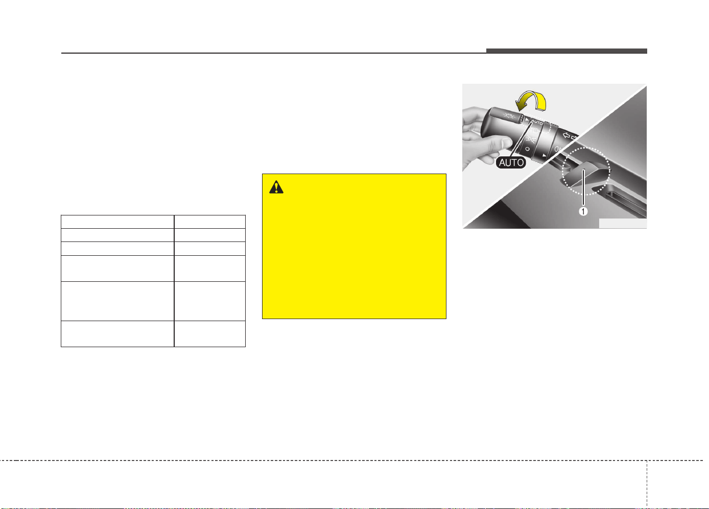
4129
Features of your vehicle
The higher the number of the switch is
positioned, the lower the headlight beam
level. Always keep the headlight beam at
the proper leveling position, or headlights
may dazzle other road users.
Listed below are the examples of proper
switch settings. For loading conditions
other than those listed below, adjust the
switch position so that the beam level
may be the nearest as the condition
obtained according to the list.
Automatic type
It automatically adjusts the headlight
beam level according to the number of
passengers and loading weight in the
luggage area.
And it offers proper headlight beam
under various conditions.
Adaptive Front Lighting System
(AFLS) (if equipped)
Adaptive front lighting system uses the
steering angle and vehicle speed, to
keep your field of vision wide by swiveling
and leveling the headlamp.
Change the switch to the AUTO position
when the engine is running. The adaptive
front lighting system will operate when
the headlamp is ON. To turn off the
AFLS, change the switch to other posi-
tions. After turning the AFLS off, head-
lamp swiveling no longer occurs, but lev-
eling operates continuously.
OYN049201
Loading condition Switch position
Driver only 0
Driver + Front passenger 0
Full passengers
(including driver)
1
Full passengers (including
driver) + Maximum permis-
sible loading
2
Driver + Maximum permis-
sible loading
3
WARNING
If it does not work properly even
though your car is inclined back-
ward according to passenger's
posture, or the headlight beam is
irradiated to the high or low posi-
tion, we recommend that the sys-
tem be inspected by an authorized
Kia dealer.
Do not attempt to inspect or
replace the wiring yourself.
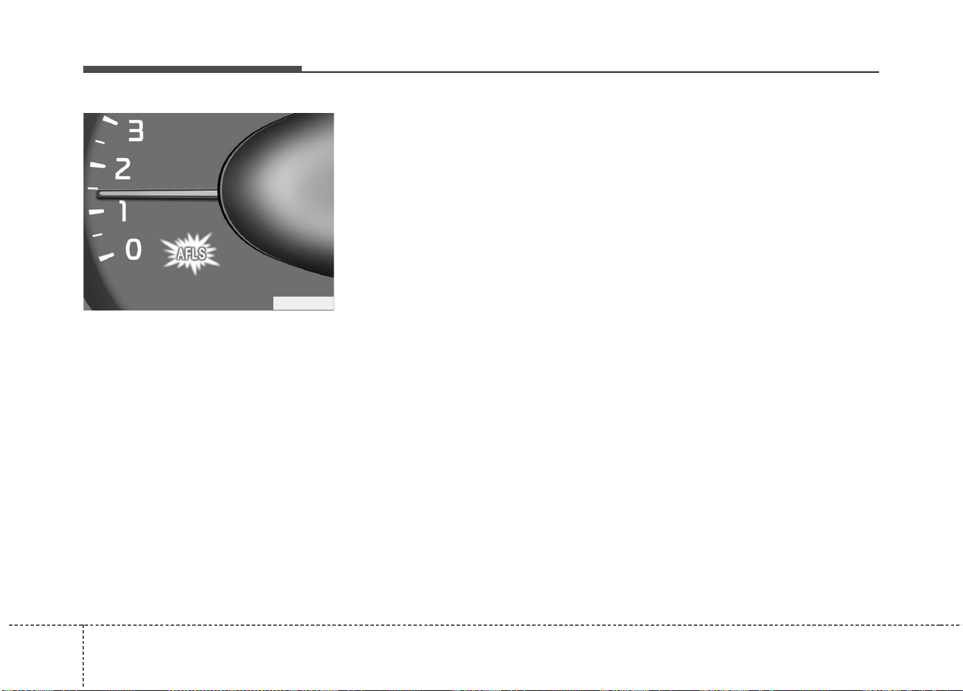
Features of your vehicle
1304
If the AFLS malfunction indicator comes
on, the AFLS is not working properly.
Drive to the nearest safe location and
restart the engine. If the indicator contin-
uously remains on, we recommend that
the system be checked by an authorized
Kia dealer.
OJD042090
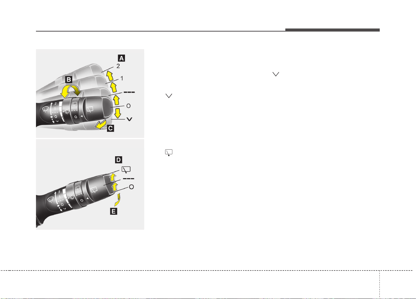
4131
Features of your vehicle
A : Wiper speed control (front)
· 2 – High wiper speed
· 1 – Low wiper speed
· --- – Intermittent wipe
· AUTO* – Automatic control wipe
· O – Off
· – Single wipe
B : Intermittent control wipe time
adjustment
C : Wash with brief wipes (front)*
D : Rear wiper/washer control*
· – Continuous wipe
· --- – Intermittent wipe
· O – Off
E : Wash with brief wipes (rear)*
* : if equipped
Windshield wipers (front)
Operates as follows when the ignition
switch is turned ON.
: For a single wiping cycle, move the
lever to this position and release it.
The wipers will operate continuously if
the lever is held in this position.
O : Wiper is not in operation
--- : Wiper operates intermittently at the
same wiping intervals. Use this mode
in light rain or mist. To vary the speed
setting, turn the speed control knob.
1 : Normal wiper speed
2 : Fast wiper speed
✽✽
NOTICE
If there is heavy accumulation of snow
or ice on the windshield, defrost the
windshield for about 10 minutes, or
until the snow and/or ice is removed
before using the windshield wipers to
ensure proper operation. If you do not
remove the snow and/or ice before using
the wiper and wash-er, it may damage
the Wiper and washer system.
WIPERS AND WASHERS
OXM049230L/OAM049048L
■
■
Front
■
■
Rear
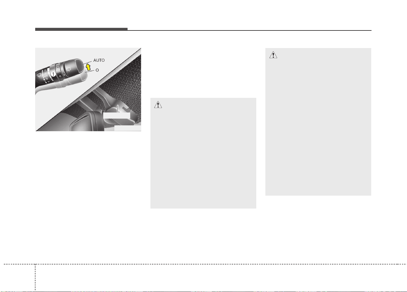
Features of your vehicle
1324
AUTO (Automatic) control
(if equipped)
The rain sensor located on the upper end
of the windshield glass senses the
amount of rainfall and controls the wiping
cycle for the proper interval. The more it
rains, the faster the wiper operates. When
the rain stops, the wiper stops.
To vary the speed setting, turn the speed
control knob (1).
If the wiper switch is set in AUTO mode
when the ignition switch is ON, the wiper
will operate once to perform a self-check
of the system. Set the wiper to off posi-
tion when the wiper is not in use.
CAUTION
When the ignition switch is ON and
the windshield wiper switch is
placed in the AUTO mode, use cau-
tion in the following situations to
avoid any injury to the hands or
other parts of the body:
• Do not touch the upper end of the
windshield glass facing the rain
sensor.
• Do not wipe the upper end of the
windshield glass with a damp or
wet cloth.
• Do not put pressure on the wind-
shield glass.
OEL049900
Rain sensor
CAUTION
When washing the vehicle, set the
wiper switch in the off position to
stop the auto wiper operation.
The wiper may operate and be dam-
aged if the switch is set in the AUTO
mode while washing the vehicle.
Do not remove the sensor cover
located on the upper end of the pas-
senger side windshield glass.
Damage to system parts could
occur and may not be covered by
your vehicle warranty.
When starting the vehicle in winter,
set the wiper switch in the off posi-
tion. Otherwise, wipers may operate
and ice may damage the windshield
wiper blades. Always remove all
snow and ice and defrost the wind-
shield properly prior to operating
the windshield wipers.
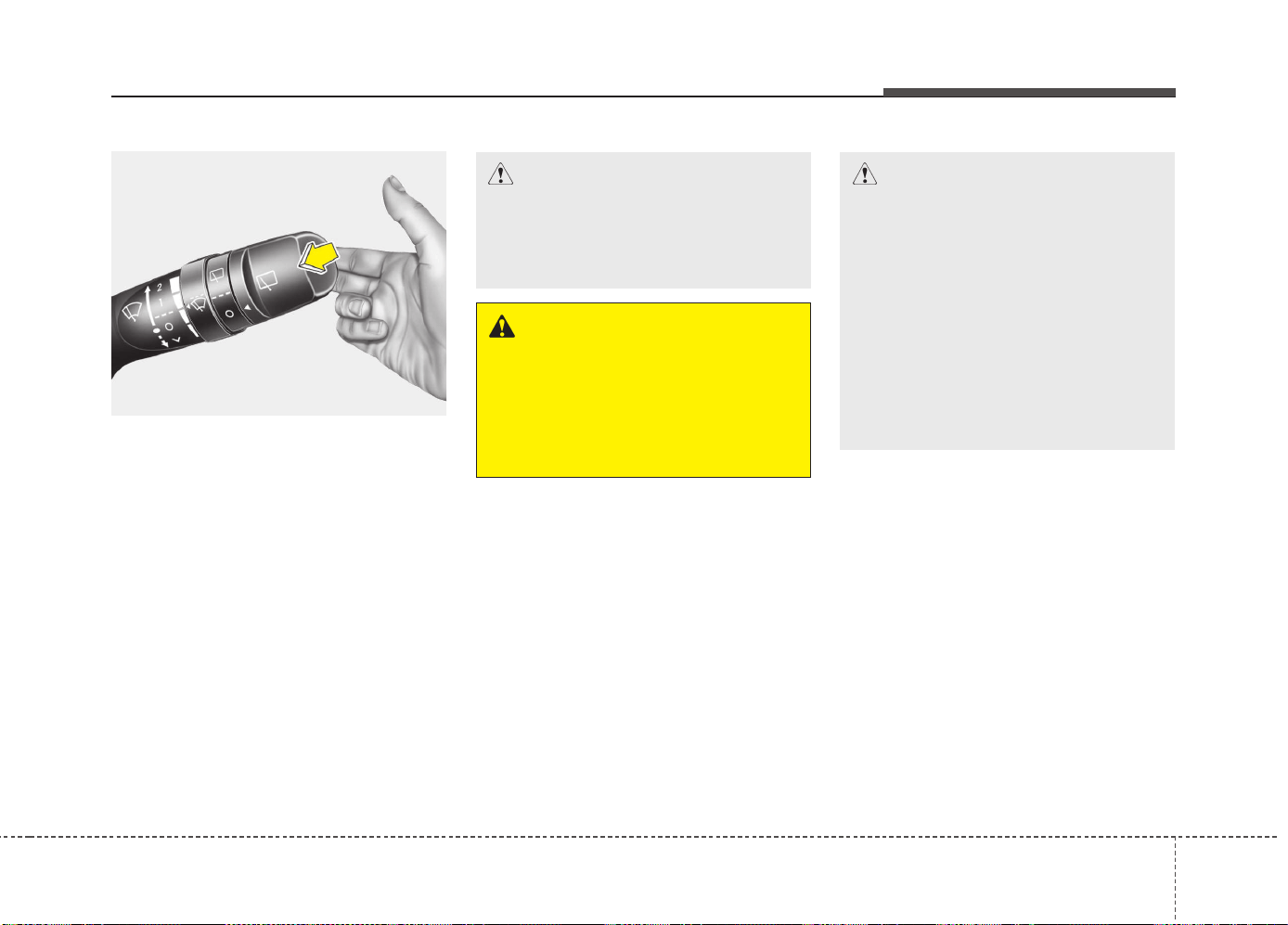
4133
Features of your vehicle
Windshield washers (front)
(if equipped)
In the O (Off) position, pull the lever gen-
tly toward you to spray washer fluid on
the windshield and to run the wipers 1-3
cycles.
Use this function when the windshield is
dirty.
The spray and wiper operation will con-
tinue until you release the lever.
If the washer does not work, check the
washer fluid level. If the fluid level is not
sufficient, you will need to add appropri-
ate non-abrasive windshield washer fluid
to the washer reservoir.
The reservoir filler neck is located in the
front of the engine compartment on the
passenger side.
OXM049048E
WARNING
Do not use the washer in freezing
temperatures without first warming
the windshield with the defrosters;
the washer solution could freeze on
the windshield and obscure your
vision.
CAUTION
• To prevent possible damage to
the wipers or windshield, do not
operate the wipers when the
windshield is dry.
• To prevent damage to the wiper
blades, do not use gasoline,
kerosene, paint thinner, or other
solvents on or near them.
• To prevent damage to the wiper
arms and other components, do
not attempt to move the wipers
manually.
CAUTION
To prevent possible damage to the
washer pump, do not operate the
washer when the fluid reservoir is
empty.
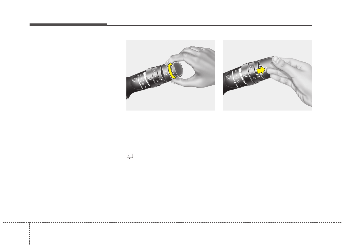
Features of your vehicle
1344
Headlight washer (if equipped)
If your vehicle is equipped with the head-
light washer it will operate at the same
time when you operate the windshield
washer. However, if this function is oper-
ated once, the headlight washer will not
operate within 15 minutes. It will operate
when the headlight is ON and the ignition
switch or engine start/stop button is in
the ON position.
The washer fluid will be sprayed on to the
headlights.
✽✽
NOTICE
• Check the headlight washers periodi-
cally to confirm that the washer fluid
is being sprayed properly onto the
headlight lenses.
• The headlight washer can be operated
15 minutes after being operated last
time.
Rear window wiper and washer
switch (if equipped)
The rear window wiper and washer
switch is located at the end of the wiper
and washer switch lever. Turn the switch
to desired position to operate the rear
wiper and washer.
- Normal wiper operation
--- - Intermittent wipe
O - Wiper is not in operation
Push the lever away from you to spray
rear washer fluid and to run the rear
wipers 1~3 cycles. The spray and wiper
operation will continue until you release
the lever.
OXM049103E OXM049125L
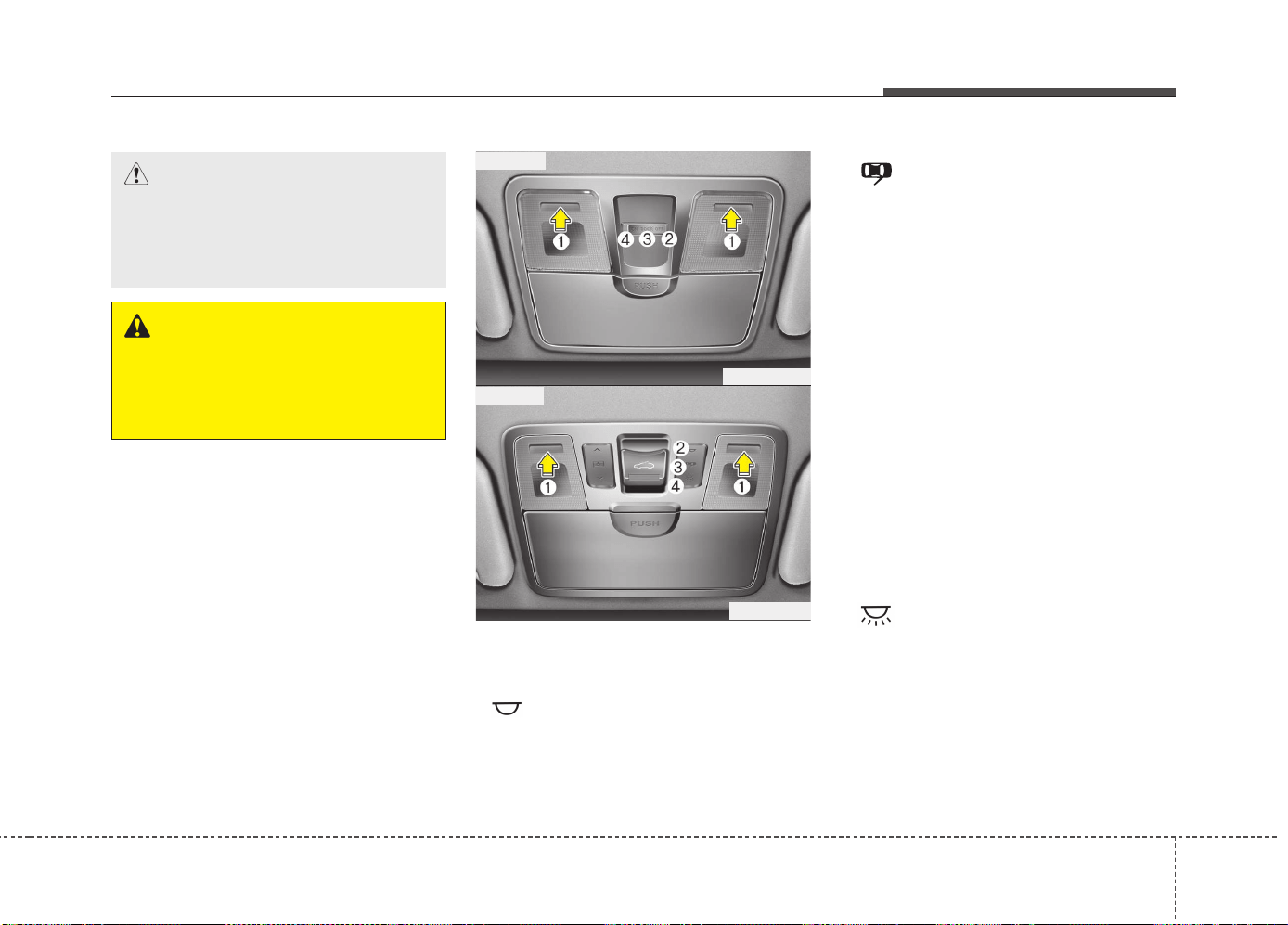
4135
Features of your vehicle
Interior lamp AUTO cut
• When all entrances are closed, if you
lock the vehicle by using the transmit-
ter or the smart key, all interior lamp
will be off after a few seconds.
• If you do not operate anything in the
vehicle after turning off the engine, the
lights will turn off after 20 minutes.
Map lamp
Press the lens (1) to turn the map lamp
on or off
• /OFF (2) : The lamps are off even
if a door is opened.
• /DOOR (3) :
- The map lamp comes on when a door
is opened. If you close the door, the
lamps go out after approximately 30
seconds.
- The map lamp comes on for approxi-
mately 30 seconds when doors are
unlocked with a transmitter or smart
key as long as the doors are not
opened.
- The map lamp will stay on for approxi-
mately 20 minutes if a door is opened
with the ignition switch in the ACC or
LOCK/OFF position.
- The map lamp will stay on continu-
ously if the door is opened with the
ignition switch in the ON position.
- The map lamp will go out immediate-
ly if the ignition switch is changed to
the ON position or all doors are
locked.
• /ON (4) : The map lamp stays on
at all times.
✽✽
NOTICE
When the lamp is turned on by pressing
the lens (1), the lamp does not turn off
even if the switch is in the OFF position
(2).
INTERIOR LIGHT
CAUTION
Do not use the interior lights for
extended periods when the engine
is not running.
It may cause battery discharge.
WARNING
Do not use the interior lights when
driving in the dark. Accidents could
happen because the view may be
obscured by interior lights.
OGD041104
OJD042091
■ Type A
■ Type B
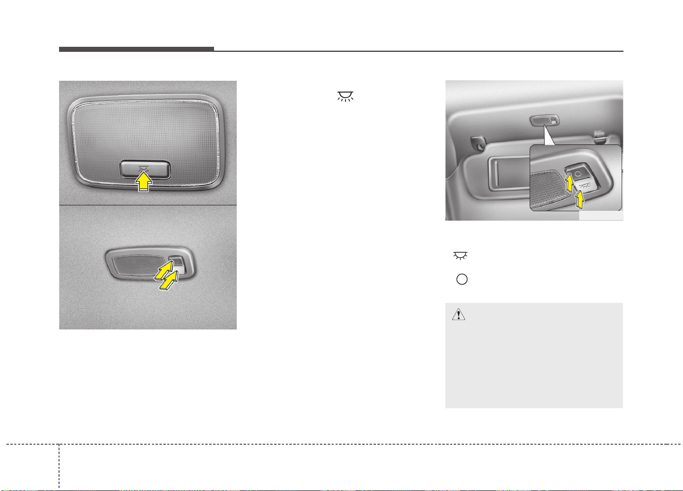
Features of your vehicle
1364
Room lamp
Type A
Press the button to turn the light on or off.
If the map lamp turns on by the map
lamp switch, the room lamp will turn on.
Type B
Press the switch to turn on the
room lamp.
Press the switch O to turn off the room
lamp.
Vanity mirror lamp (if equipped)
Push the switch to turn the light on or off.
• : The lamp will turn on if this button
is pressed.
• : The lamp will turn off if this button
is pressed.
OGD041151
■ Type B
OGDE041216
■ Type A
OLM049105
CAUTION
- Vanity mirror lamp
Always have the switch in the off
position when the vanity mirror
lamp is not in use. If the sunvisor is
closed without the lamp off, it may
discharge the battery or damage
the sunvisor.
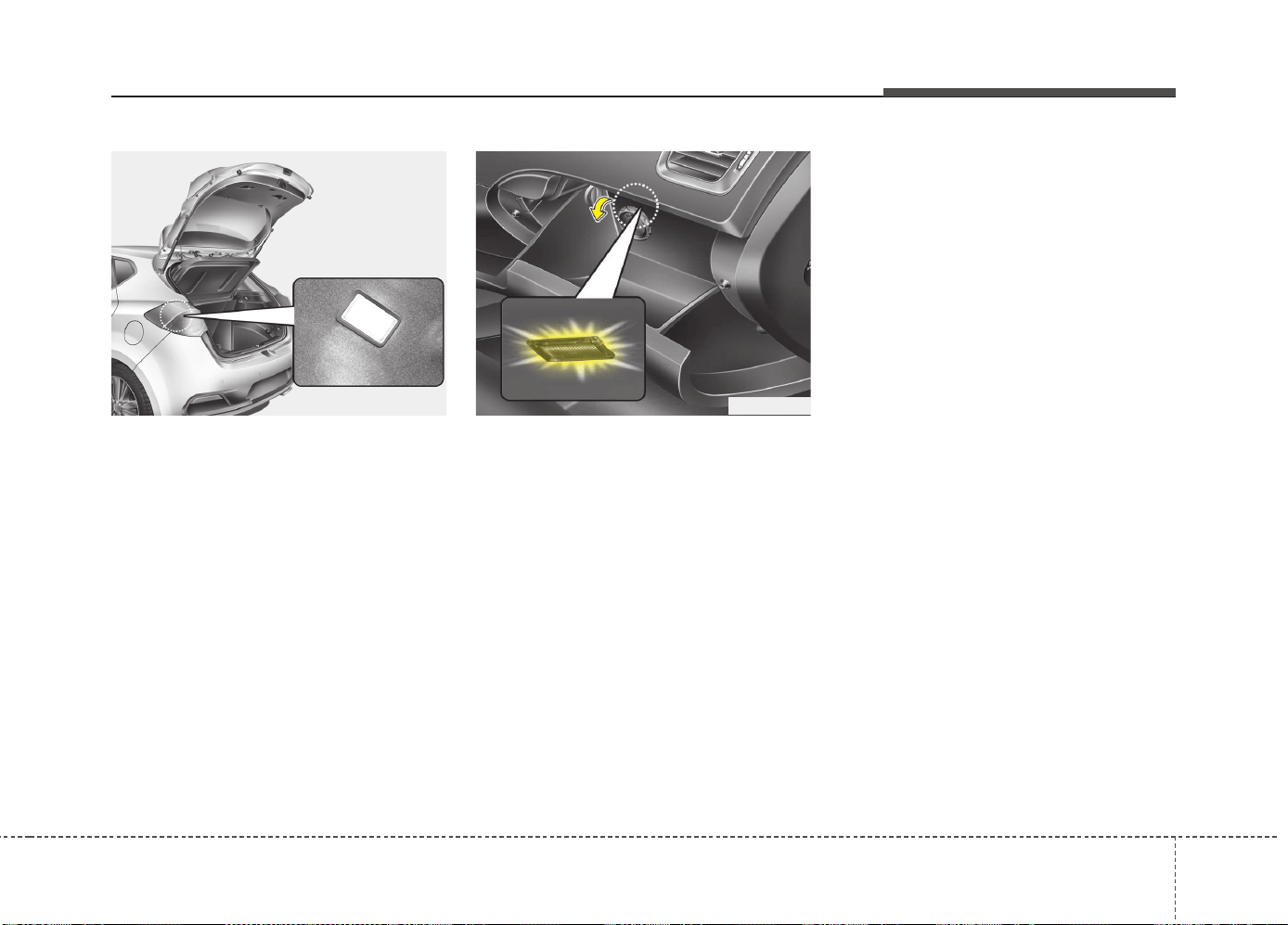
4137
Features of your vehicle
❈ The actual luggage room in the vehicle may
differ from the illustration.
Luggage room lamp
The luggage room lamp comes on when
the tailgate is opened.
Glove box lamp
The glove box lamp comes on when the
glove box is opened.
OJD042092 OJD042093

Features of your vehicle
1384
Headlamp welcome
When the headlight(light switch in the
headlight or AUTO position) is on and all
doors (and tailgate) are locked and
closed, the headlight, position light and
tail light will come on for 15 seconds if
any of the below is performed.
• Without smart key system
- When the door unlock button is
pressed on the transmitter.
• With the smart key system
- When the door unlock button is
pressed on the smart key.
At this time, if you press the door lock but-
ton (on the transmitter or smart key), the
lights will turn off immediately.
Interior light
When the interior light switch is in the
DOOR position and all doors (and tail-
gate) are locked and closed, the room
lamp will come on for 30 seconds if any
of the below is performed.
• Without smart key system
- When the door unlock button is
pressed on the transmitter.
• With the smart key system
- When the door unlock button is
pressed on the smart key.
- When the button of the outside door
handle is pressed.
At this time, if you press the door lock but-
ton, the lamps will turn off immediately.
Puddle lamp (if equipped)
When all doors are locked and closed,
the puddle lamp will come on for 15 sec-
onds if any of the below is performed.
• Without smart key system
- When the door unlock button is
pressed on the transmitter.
• With the smart key system
- When the door unlock button is
pressed on the smart key.
- When the button of the outside door
handle is pressed.
- When the vehicle is approached with
the smart key in possession.
At this time, if you press the door lock but-
ton, the lamps will turn off immediately.
WELCOME SYSTEM (IF EQUIPPED)
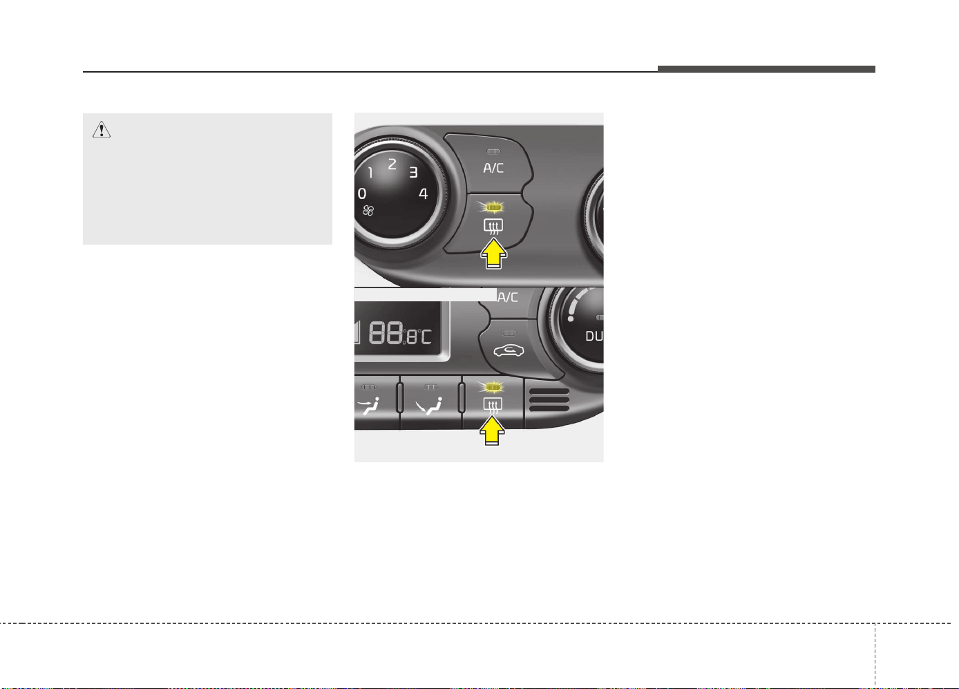
4139
Features of your vehicle
✽✽
NOTICE
If you want to defrost and defog the
front windshield, refer to “Windshield
Defrosting and Defogging” in this chap-
ter.
Rear window defroster
The defroster heats the window to
remove frost, fog and thin ice from the
interior and exterior of the rear window,
while engine is running.
• To activate the rear window defroster,
press the rear window defroster button
located in the center facia switch
panel. The indicator on the rear win-
dow defroster button illuminates when
the defroster is ON.
• To turn off the defroster, press the rear
window defroster button again.
✽✽
NOTICE
• If there is heavy accumulation of snow
on the rear window, brush it off before
operating the rear defroster.
• The rear window defroster automati-
cally turns off after approximately 20
minutes or when the ignition switch is
turned off.
Outside mirror defroster
(if equipped)
The outside mirror defroster will operate
at the same time you turn on the rear
window defroster.
Front wiper deicer (if equipped)
The front wiper deicer will operate at the
same time you turn on the rear window
defroster.
DEFROSTER
CAUTION
To prevent damage to the conduc-
tors bonded to the inside surface of
the rear window, never use sharp
instruments or window cleaners
containing abrasives to clean the
window.
OJD042094
OJD042095
■ Manual climate control
■ Automatic climate control
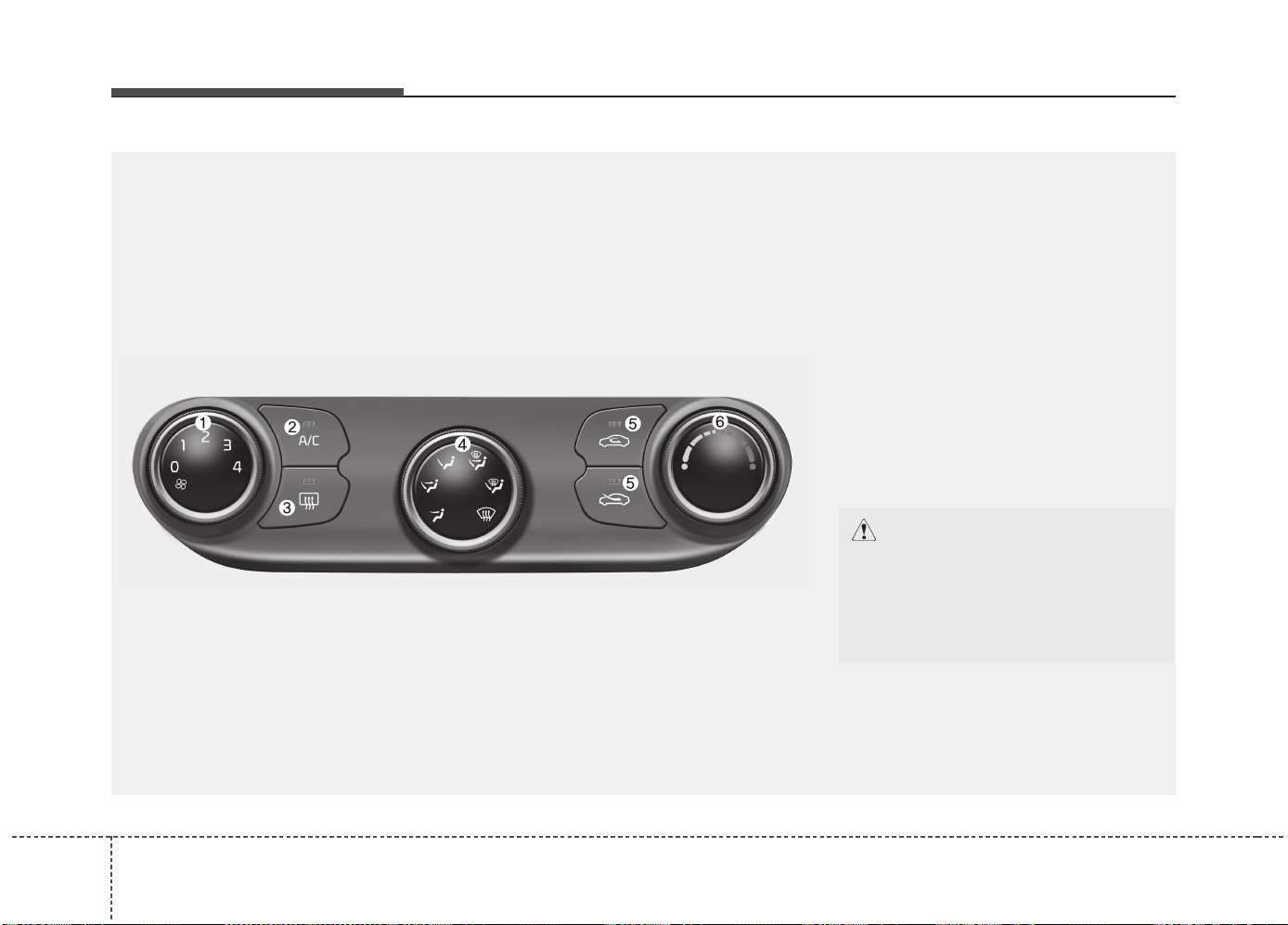
Features of your vehicle
1404
MANUAL CLIMATE CONTROL SYSTEM (IF EQUIPPED)
OJD042100
1. Fan speed control knob
2. Air conditioning button
3. Rear window defroster button
4. Mode selection knob
5. Air intake control button
6. Temperature control knob
CAUTION
Operating the blower when the igni-
tion switch is in the ON position
could cause the battery to dis-
charge. Operate the blower when the
ignition switch is in the ON position.
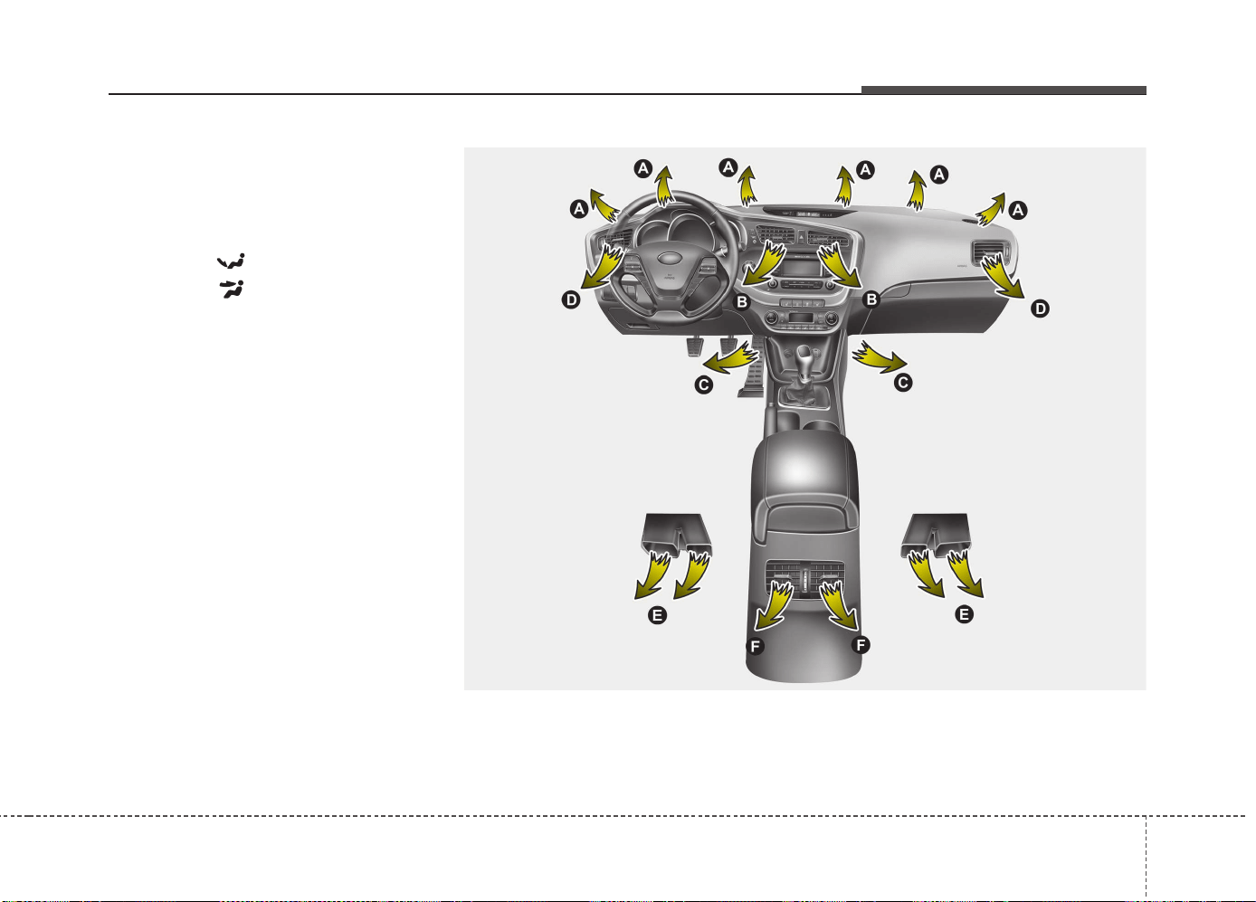
4141
Features of your vehicle
Heating and air conditioning
1. Start the engine.
2. Set the mode to the desired position.
To improve the effectiveness of heat-
ing and cooling:
- Heating:
- Cooling:
3. Set the temperature control to the
desired position.
4. Set the air intake control to the outside
(fresh) air or recirculated position.
5. Set the fan speed control to the
desired speed.
6. If air conditioning is desired, turn the air
conditioning system on. (if equipped)
OJD042102
((
((
ii
ii
ff
ff
ee
ee
qq
qq
uu
uu
ii
ii
pp
pp
pp
pp
ee
ee
dd
dd
))
))
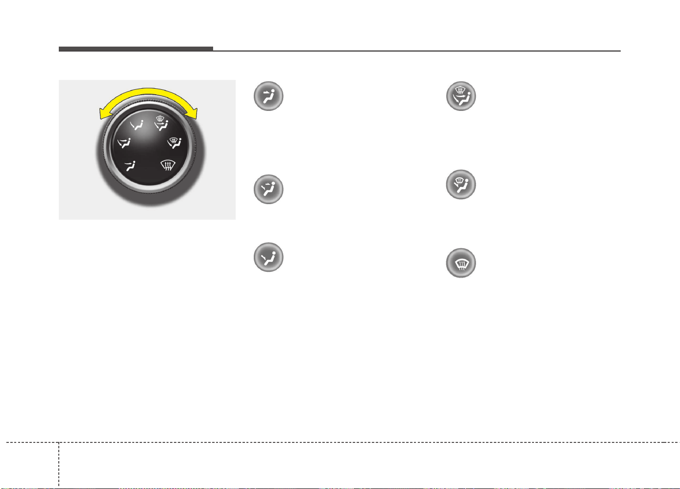
Features of your vehicle
1424
Mode selection
The mode selection knob controls the
direction of the air flow through the venti-
lation system.
Air can be directed to the floor, dash-
board outlets, or windshield. Six symbols
are used to represent Face, Bi-Level,
Floor, Face / Floor / Defrost, Floor /
Defrost and Defrost air position.
Face-Level (B, D, F)
Air flow is directed toward the upper body
and face. Additionally, each outlet can be
controlled to direct the air discharged
from the outlet.
Bi-Level (B, D, C, E, F)
Air flow is directed towards the face and
the floor.
Floor-Level (A, C, D, E)
Most of the air flow is directed to the
floor, with a small amount of the air being
directed to the windshield and side win-
dow defrosters.
Face/Floor/Defrost-Level
(A, B, C, D, E, F)
Most of the air flow is directed towards
the face, the floor and the windshield with
a small amount of air directed to the side
window defrosters.
Floor/Defrost-Level (A, C, E, D)
Most of the air flow is directed to the floor
and the windshield with a small amount
directed to the side window defrosters.
Defrost-Level (A, D)
Most of the air flow is directed to the
windshield with a small amount of air
directed to the side window defrosters.
OJD042104
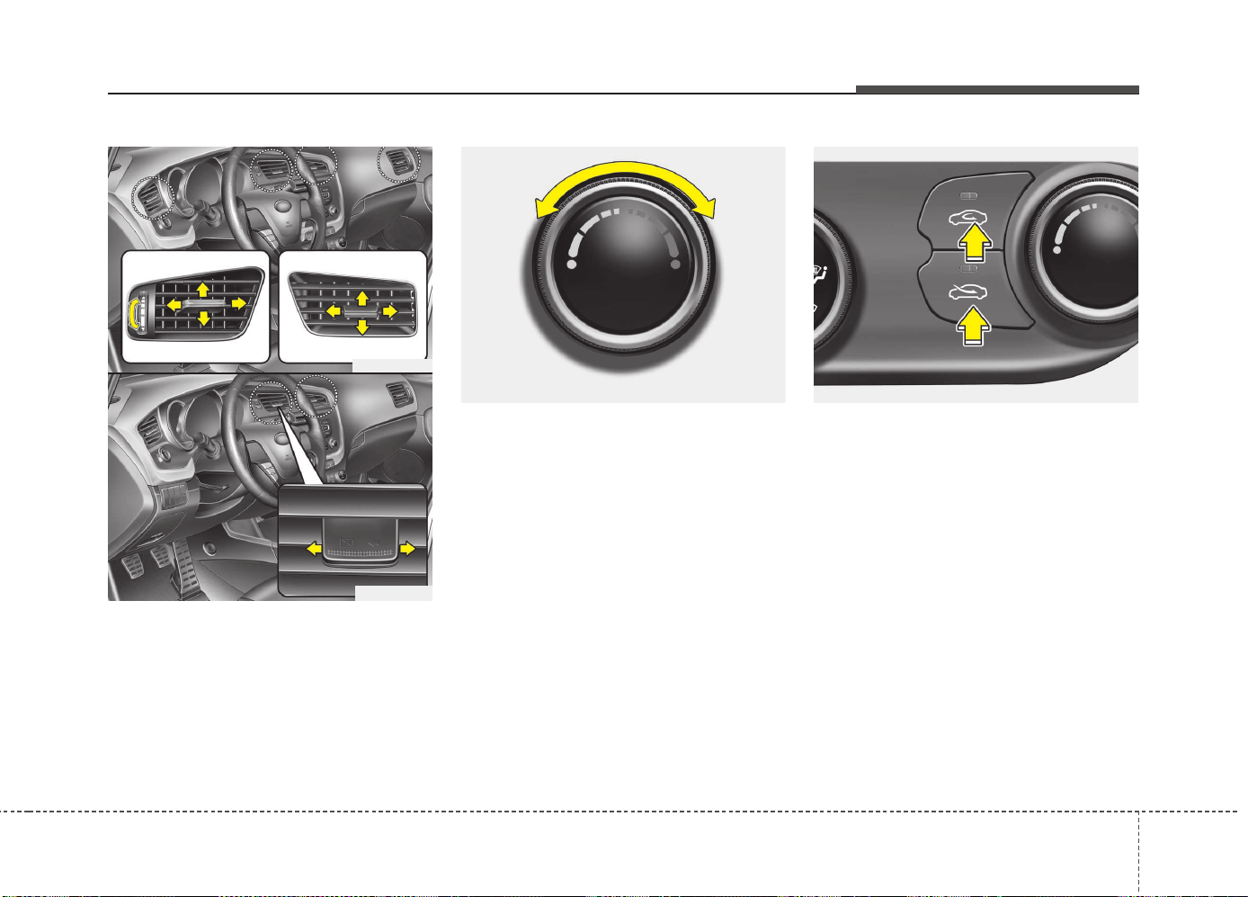
4143
Features of your vehicle
Instrument panel vents
The outlet vents can be opened or closed
separately using the thumbwheel or vent
control lever.
Also, you can adjust the direction of air
delivery from these vents using the vent
control lever as shown.
Temperature control
The temperature control knob allows you
to control the temperature of the airflow
in the vehicle.
To change the temperature:
• Turn the knob to the right to increase
temperature.
• Turn the knob to the left to decrease
temperature.
Air intake control
The air intake control is used to select
the outside (fresh) air position or recircu-
lated air position.
To change the air intake control position,
press the control button.
OJD042105
OJD042107
OJD042108
OJD042106
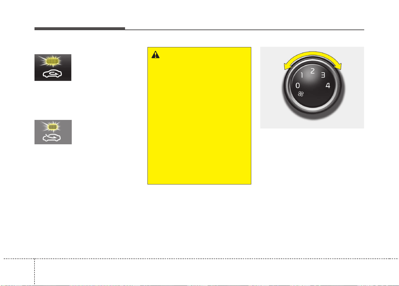
Features of your vehicle
1444
Recirculated air position
With the recirculated air
position selected, air
from the passenger
compartment will be
drawn through the heat-
ing system and heated
or cooled according to
the function selected.
Outside (fresh) air position
With the outside (fresh)
air position selected, air
enters the vehicle from
outside and is heated or
cooled according to the
function selected.
✽✽
NOTICE
Prolonged operation of the heater in the
recirculated air position (without air
conditioning selected) may cause fogging
of the windshield and side windows and
the air within the passenger compart-
ment may become stale.
In addition, prolonged use of the air con-
ditioning with the recirculated air posi-
tion selected will result in excessively dry
air in the passenger compartment.
Fan speed control
The ignition switch must be in the ON
position for fan operation.
The fan speed control knob allows you to
control the fan speed of the air flowing
from the ventilation system. To change
the fan speed, turn the knob to the right
for higher speed or left for lower speed.
Setting the fan speed control knob to the
“0” position turns off the fan.
WARNING
• The continuous use of recirculat-
ed air in the climate control sys-
tem may increase humidity inside
the vehicle, causing the glass to
fog and obscuring visibility.
• Do not sleep in a vehicle with the
air conditioning or heating sys-
tem on. It may cause serious
harm or death due to a drop in the
oxygen level and/or body temper-
ature.
• The continuous use of recirculat-
ed air in the climate control sys-
tem can produce drowsiness or
sleepiness, which may result in a
loss of vehicle control. Set the air
intake control to the outside
(fresh) air position as much as
possible while driving.
OJD042101
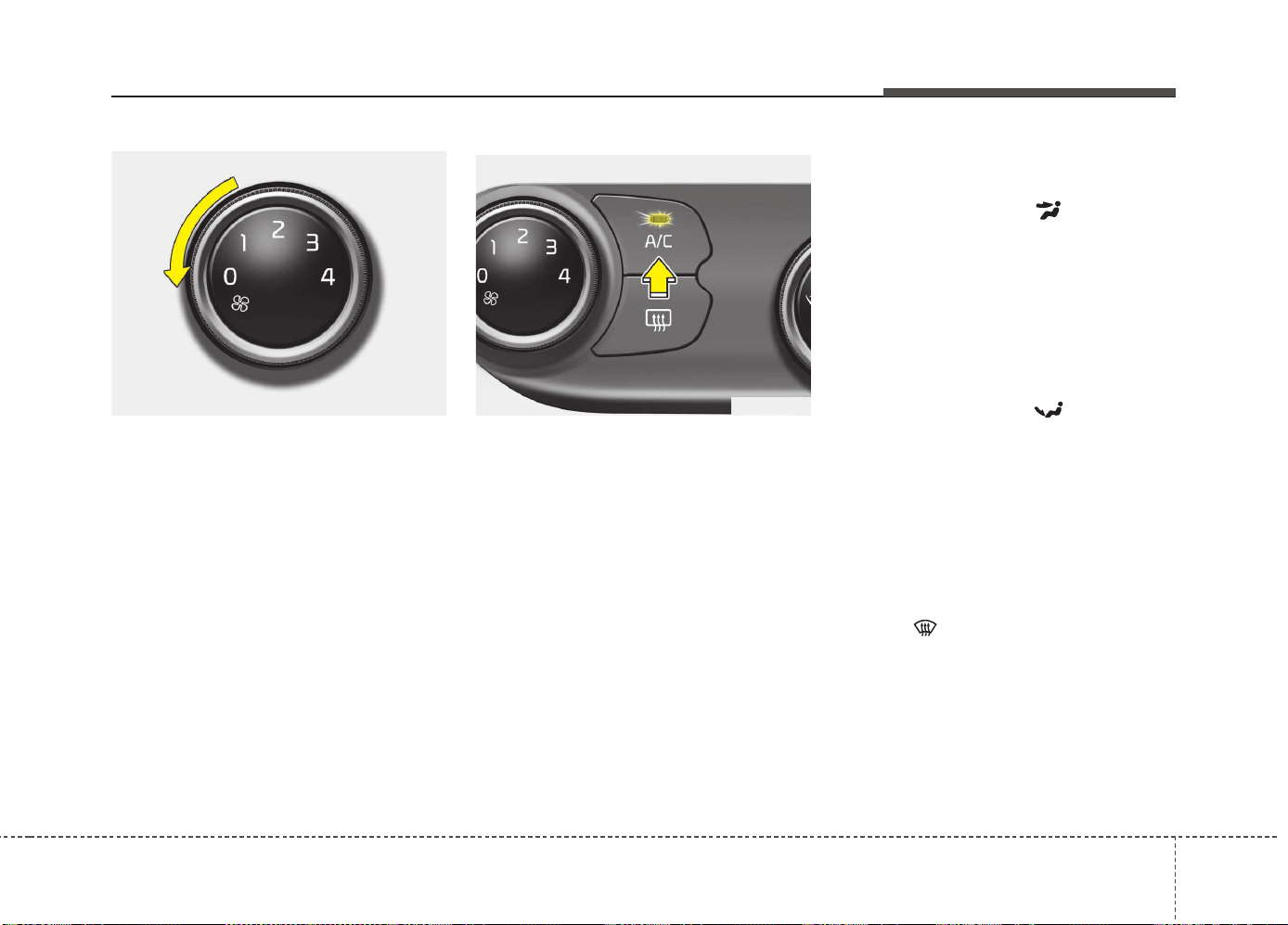
4145
Features of your vehicle
To turn off the blowers
To turn off the blowers, turn the fan
speed control knob to the "0" position.
Air conditioning (if equipped)
Press the A/C button to turn the air con-
ditioning system on (indicator light will
illuminate). Press the button again to turn
the air conditioning system off.
System operation
Ventilation
1. Set the mode to the position.
2. Set the air intake control to the outside
(fresh) air position.
3. Set the temperature control to the
desired position.
4. Set the fan speed control to the
desired speed.
Heating
1. Set the mode to the position.
2. Set the air intake control to the outside
(fresh) air position.
3. Set the temperature control to the
desired position.
4. Set the fan speed control to the
desired speed.
5. If dehumidified heating is desired, turn
the air conditioning system on.
• If the windshield fogs up, set the mode
to the position.
OJD042103OJD043247
Features of your vehicle
1464
Operation Tips
• To keep dust or unpleasant fumes from
entering the vehicle through the venti-
lation system, temporarily set the air
intake control to the recirculated air
position. Be sure to return the control
to the fresh air position when the irrita-
tion has passed to keep fresh air in the
vehicle. This will help keep the driver
alert and comfortable.
• Air for the heating/cooling system is
drawn in through the grilles just ahead
of the windshield. Care should be
taken that these are not blocked by
leaves, snow, ice or other obstructions.
• To prevent interior fog on the wind-
shield, set the air intake control to the
fresh air position and fan speed to the
desired position, turn on the air condi-
tioning system, and adjust the temper-
ature control to desired temperature.
Air conditioning (if equipped)
Kia Air Conditioning Systems are filled
with environmentally friendly refrigerant*.
1. Start the engine. Push the air condi-
tioning button.
2. Set the mode to the position.
3. Set the air intake control to the outside
air or recirculated air position.
4. Adjust the fan speed control and tem-
perature control to maintain maximum
comfort.
*: Your vehicle is filled with R-134a or R-
1234yf according to the regulation in
your country at the time of producing.
You can find out which air conditioning
refrigerant is applied to your vehicle at
the label inside of hood. Refer to chap-
ter 8 for more detail location of air con-
ditioning refrigerant label.
CAUTION
• The refrigerant system should
only be serviced by trained and
certified technicians to insure
proper and safe operation.
• The refrigerant system should be
serviced in a well-ventilated place.
• The air conditioning evaporator
(cooling coil) shall never be
repaired or replaced with one
removed from a used or salvaged
vehicle and new replacement
MAC evaporators shall be certi-
fied (and labeled) as meeting SAE
Standard J2842.
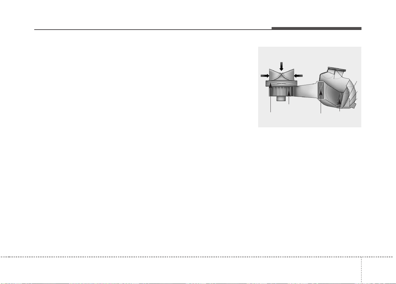
4147
Features of your vehicle
✽✽
NOTICE
• When using the air conditioning sys-
tem, monitor the temperature gauge
closely while driving up hills or in
heavy traffic when outside tempera-
tures are high. Air conditioning sys-
tem operation may cause engine over-
heating. Continue to use the blower
fan but turn the air conditioning sys-
tem off if the temperature gauge indi-
cates engine overheating.
• When opening the windows in humid
weather air conditioning may create
water droplets inside the vehicle.
Since excessive water droplets may
cause damage to electrical equipment,
air conditioning should only be used
with the windows closed.
Air conditioning system operation tips
• If the vehicle has been parked in direct
sunlight during hot weather, open the
windows for a short time to let the hot
air inside the vehicle escape.
• Use air conditioning to reduce humidi-
ty and moisture inside the vehicle on
rainy or humid days.
• During air conditioning system opera-
tion, you may occasionally notice a slight
change in engine speed as the air con-
ditioning compressor cycles. This is a
normal system operation characteristic.
• Use the air conditioning system every
month only for a few minutes to ensure
maximum system performance.
• When using the air conditioning sys-
tem, you may notice clear water drip-
ping (or even puddling) on the ground
under the passenger side of the vehi-
cle. This is a normal system operation
characteristic.
• Operating the air conditioning system
in the recirculated air position provides
maximum cooling, however, continual
operation in this mode may cause the
air inside the vehicle to become stale.
• During cooling operation, you may
occasionally notice a misty air flow
because of rapid cooling and humid air
intake. This is a normal system opera-
tion characteristic.
Climate control air filter
The climate control air filter installed
behind the glove box filters the dust or
other pollutants that come into the vehi-
cle from the outside through the heating
and air conditioning system. If dust or
other pollutants accumulate in the filter
over a period of time, the air flow from the
air vents may decrease, resulting in
moisture accumulation on the inside of
the windshield even when the outside
(fresh) air position is selected. If this hap-
pens, we recommend that the climate
control air filter be replaced by an author-
ized Kia dealer.
1LDA5047
Outside air
Recirculated
air
Climate control
air filter
Blower
Evaporator
core
Heater core
Features of your vehicle
1484
✽✽
NOTICE
• Replace the filter according to the
Maintenance Schedule.
If the car is being driven in severe
conditions such as dusty, rough roads,
more frequent climate control air fil-
ter inspections and changes are
required.
• When the air flow rate suddenly
decreases, we recommend that the
system be checked by an authorized
Kia dealer.
Checking the amount of air con-
ditioner refrigerant and compres-
sor lubricant
When the amount of refrigerant is low,
the performance of the air conditioning is
reduced. Overfilling also has a bad influ-
ence on the air conditioning system.
Therefore, if abnormal operation is found,
we recommend that the system be inspect-
ed by an authorized Kia dealer.
*: Your vehicle is filled with R-134a or R-
1234yf according to the regulation in
your country at the time of producing.
You can find out which air conditioning
refrigerant is applied your vehicle at
the label inside of hood. Refer to chap-
ter 8 for more detail location of air con-
ditioning refrigerant label.
WARNING - Vehicles
equipped with R-1234yf*
Because the refrigerant
is mildly inflammable
and at very high pres-
sure, the air conditioning
system should only be
serviced by trained and
certified technicians. It is
important that the cor-
rect type and amount of
oil and refrigerant is used.
Otherwise, it may cause damage to
the vehicle and personal injury.
WARNING - Vehicles
equipped with R-134a*
Because the refrigerant
is at very high pressure,
the air conditioning sys-
tem should only be
serviced by trained and
certified technicians. It is important
that the correct type and amount of
oil and refrigerant is used.
Otherwise, it may cause damage to
the vehicle and personal injury.
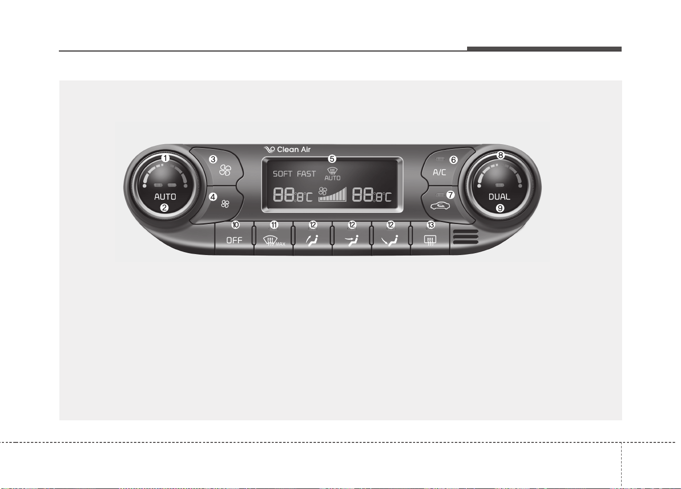
4149
Features of your vehicle
AUTOMATIC CLIMATE CONTROL SYSTEM (IF EQUIPPED)
OJD042109
1. Driver's temperature control knob
2. AUTO (automatic control) button
3. Fan speed control button (Higher speed)
4. Fan speed control button (Lower speed)
5. Climate control display
6. Air conditioning button
7. Air intake control button
8. Passenger's temperature control knob
9. Dual temperature control selection button
10. OFF button
11. Front windshield defroster button
12. Mode selection button
13. Rear window defroster button
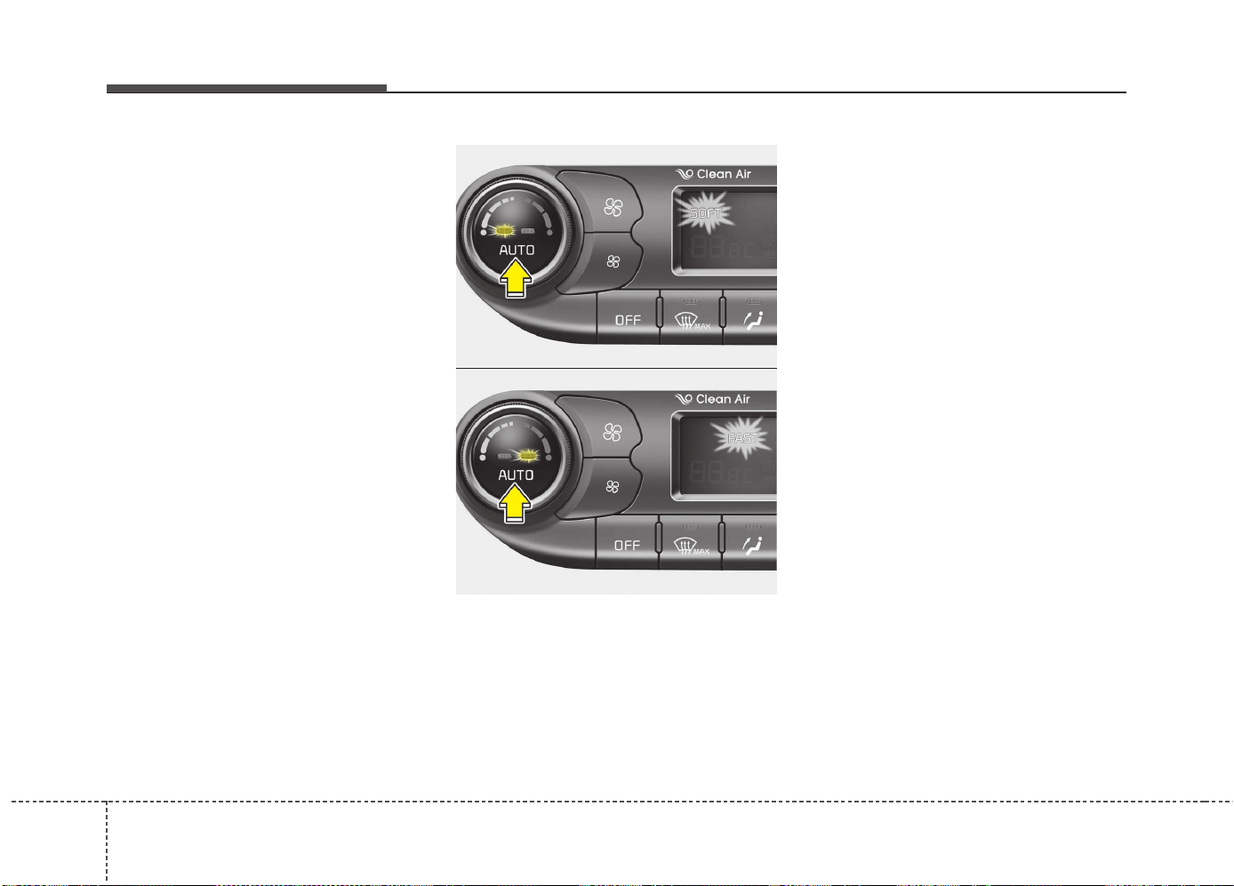
Features of your vehicle
1504
Automatic heating and air condi-
tioning
The automatic climate control system is
controlled by simply setting the desired
temperature.
You can choose either the soft mode or
fast mode to select the fan speed.
Soft mode : The wind blows gently.
Fast mode : The wind blows heavier than
the soft mode to reach the selected tem-
perature fast.
Each time you press the AUTO button,
the mode will change as follows:
Soft mode ↔ Fast mode
The Full Automatic Temperature Control
(FATC) system automatically controls the
heating and cooling system as follows:
1. Press the AUTO button.
The modes, fan speeds, air intake and
air-conditioning will be controlled auto-
matically according to the temperature
setting.
OJD042110
OJD042119
Soft mode
Fast mode
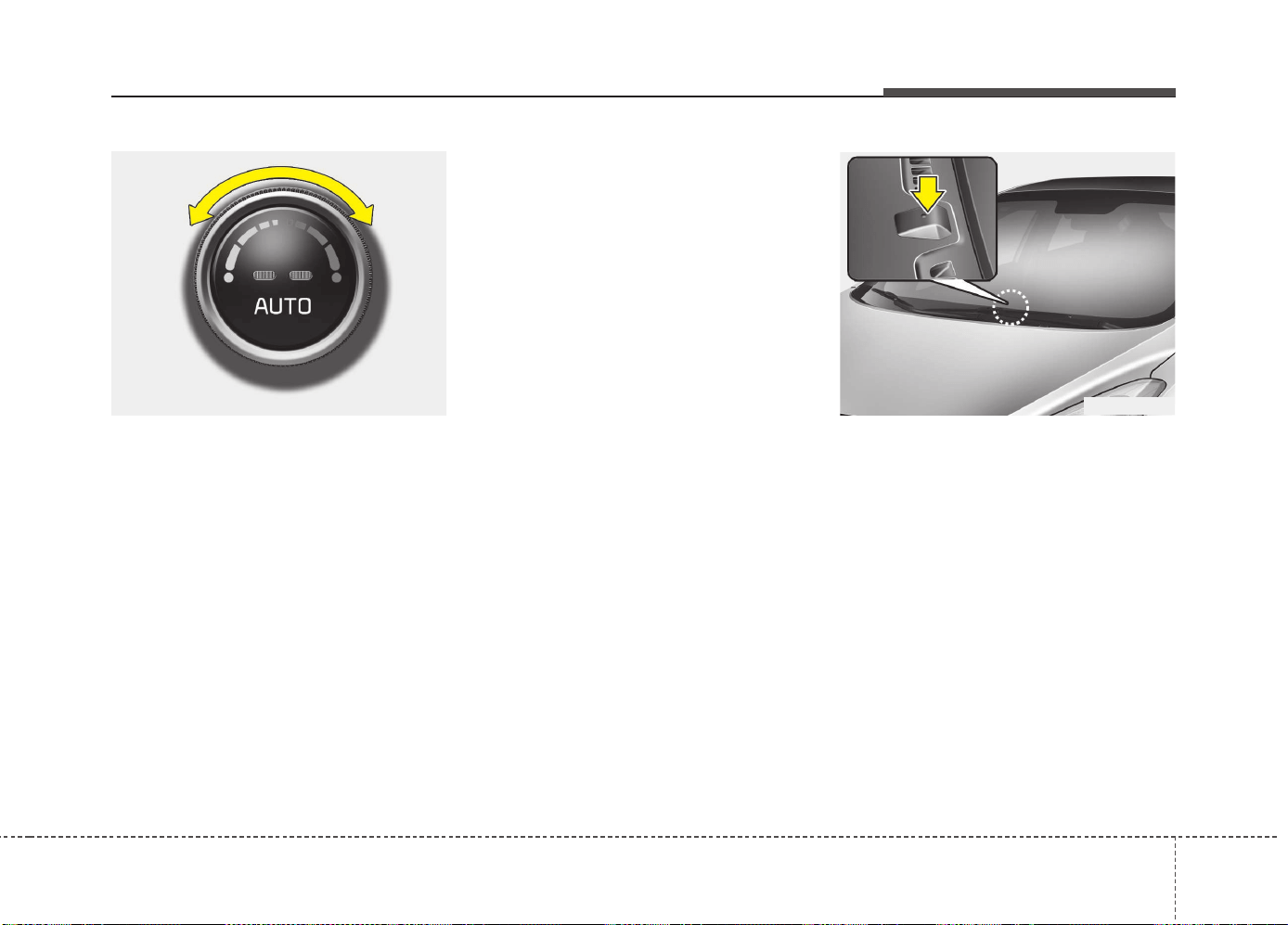
4151
Features of your vehicle
2. Turn the temperature control knob to
set the desired temperature.
✽✽
NOTICE
• To turn the automatic operation off,
select any button of the following:
- Mode selection button
- Front windshield defrost button
(Press the button one more time to
deselect the front windshield
defroster function. The 'AUTO' sign
will illuminate on the information
display once again.)
- Fan speed control button
The selected function will be con-
trolled manually while other functions
operate automatically.
• For your convenience and to improve
the effectiveness of the climate con-
trol, use the AUTO button and set the
temperature to 22°C/71°F (23°C/73°F
-Except Europe).
✽
✽
NOTICE
Placing any object over the sensor on
the instrument panel may interfere with
the heating and cooling system.
OGD041120OJD042230
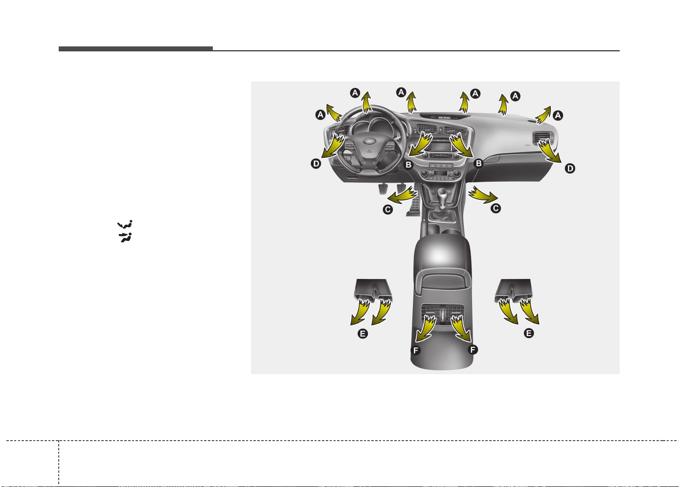
Features of your vehicle
1524
Manual heating and air condition-
ing
The heating and cooling system can be
controlled manually by pressing buttons
or turning knob(s) other than the AUTO
button. In this case, the system works
sequentially according to the order of
buttons or knob(s) selected.
1. Start the engine.
2. Set the mode to the desired position.
To improve the effectiveness of heat-
ing and cooling:
- Heating:
- Cooling:
3. Set the temperature control to the
desired position.
4. Set the air intake control to the outside
(fresh) air or recirculated position.
5. Set the fan speed control to the
desired speed.
6. If air conditioning is desired, turn the
air conditioning system on.
Press the AUTO button in order to con-
vert to full automatic control of the sys-
tem.
Mode selection
The mode selection button controls the direction of the airflow in the vehicle.
If you push the button once, the corresponding switch will turn on, and if you push the
button again, the switch will turn off.
OJD042102
((
((
ii
ii
ff
ff
ee
ee
qq
qq
uu
uu
ii
ii
pp
pp
pp
pp
ee
ee
dd
dd
))
))
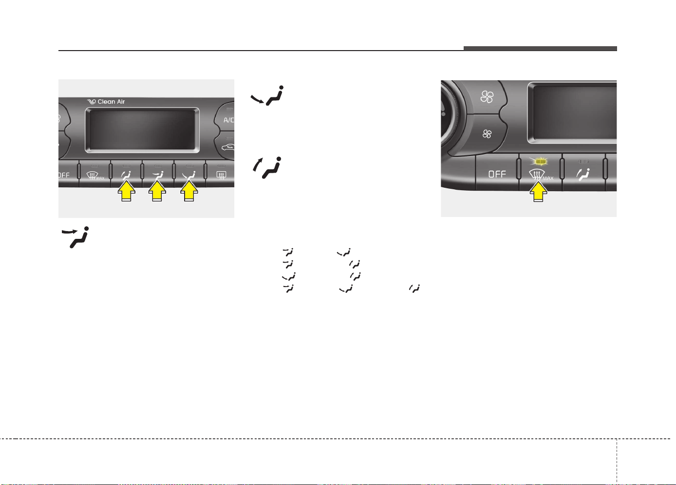
4153
Features of your vehicle
Face-Level (B, D, F*)
Air flow is directed toward the upper body
and face. Additionally, each outlet can be
controlled to direct the air discharged
from the outlet.
* : if equipped
Floor-Level (A, C, D, E)
Most of the air flow is directed to the
floor.
Defrost-Level (A, D)
Most of the air flow is directed to the
windshield.
Also you may select 2~3 modes at the
same time.
- face ( ) + floor ( ) mode
- face ( ) + defrost ( ) mode
- floor ( ) + defrost ( ) mode
- face ( ) + floor ( ) + defrost ( )
mode
Maximum (MAX) defrost mode
When you select the MAX defrost mode,
the following system will set automatically:
• The air conditioning system will be turn
on.
• The outside(fresh) air position will be
selected.
• The fan speed will set to the high
speed.
To turn the MAX defrost mode off, press
the mode button or MAX defrost button
again or AUTO button.
OJD042116 OJD042122
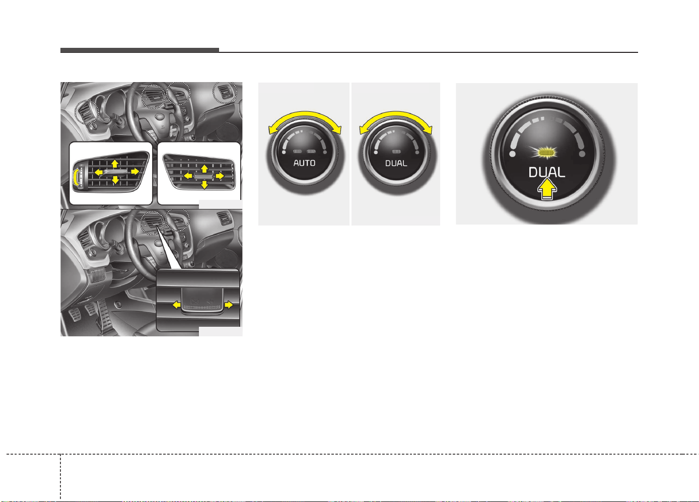
Features of your vehicle
1544
Instrument panel vents
The outlet vents can be opened or closed
separately using the thumbwheel or vent
control lever.
Also, you can adjust the direction of air
delivery from these vents using the vent
control lever as shown.
Temperature control
The temperature will increase to the
maximum (HI) by turning the knob to the
right extremely.
The temperature will decrease to the
minimum (Lo) by turning the knob to the
left extremely.
When turning the knob, the temperature
will increase or decrease by 0.5°C/1°F.
When set to the lowest temperature set-
ting, the air conditioning will operate con-
tinuously.
Operate the driver’s side temperature
control to adjust the driver side tempera-
ture. Operate the passenger’s side tem-
perature control to adjust the passenger
side temperature.
Adjusting the driver and passenger side
temperature individually
1. Press the DUAL button to operate the
driver and passenger side temperature
individually. Also, if the passenger side
temperature control knob is operated,
it will automatically change to the
DUAL mode as well.
2. Operate the driver side temperature
control to adjust the driver side tem-
perature. Operate the passenger side
temperature control to adjust the pas-
senger side temperature.
When the driver side temperature is set
to the highest (HIGH) or lowest (LOW)
temperature, the DUAL mode deacti-
vates for maximum heating or cooling.
OJD042113
■ Driver’s side ■ Passenger’s side
OJD042112
OJD042107
OJD042108
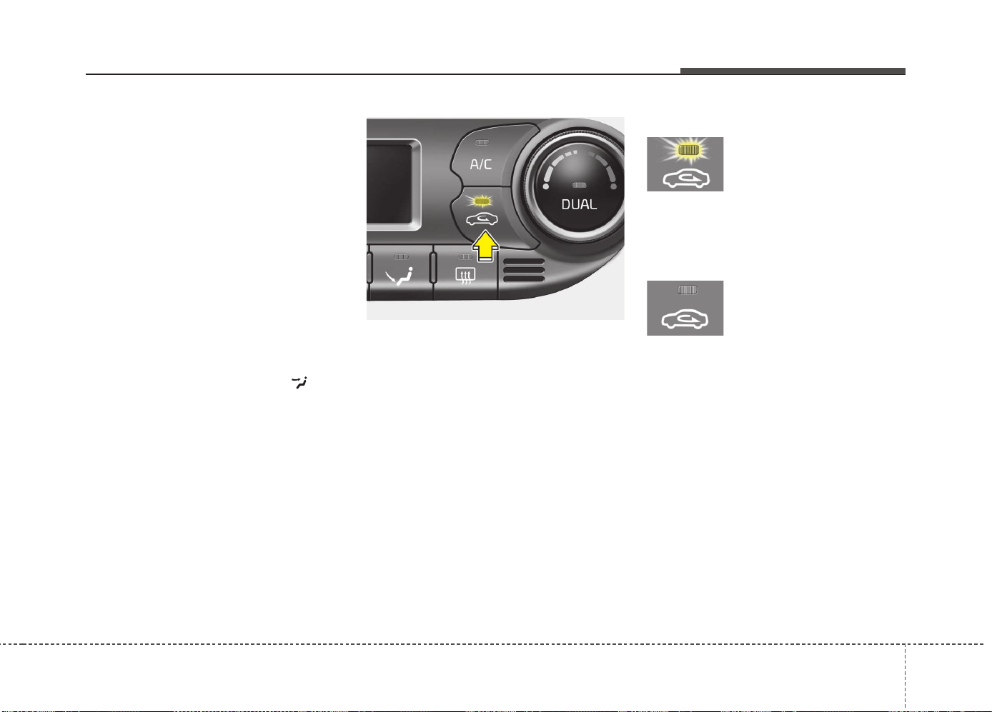
4155
Features of your vehicle
Adjusting the driver and passenger side
temperature equally
1. Press the DUAL button again to deac-
tivate DUAL mode. The passenger
side temperature will be set to the
same temperature as the driver side.
2. Operate the driver side temperature
control button. The driver and passen-
ger side temperature will be adjusted
equally.
Temperature conversion
You can switch the temperature mode
between Centigrade to Fahrenheit as
follows:
While pressing the DUAL button, press
the Face-Level selection button for 3
seconds or more.
The display will change from Centigrade
to Fahrenheit, or from Fahrenheit to
Centigrade.
✽✽
NOTICE
If the battery has been discharged or
disconnected, the temperature mode
display will reset to Centigrade.
Air intake control
This is used to select the outside (fresh)
air position or recirculated air position.
To change the air intake control position,
push the control button.
Recirculated air position
With the recirculated air
position selected, air from
the passenger compart-
ment will be drawn through
the heating system and
heated or cooled according
to the function selected.
Outside (fresh) air position
With the outside (fresh) air
position selected, air
enters the vehicle from out-
side and is heated or
cooled according to the
function selected.
✽✽
NOTICE
Prolonged operation of the heater in the
recirculated air position (without air
conditioning selected) may cause fog-
ging of the windshield and side windows
and the air within the passenger com-
partment may become stale.
In addition, prolonged use of the air con-
ditioning with the recirculated air posi-
tion selected will result in excessively dry
air in the passenger compartment.
OJD042117
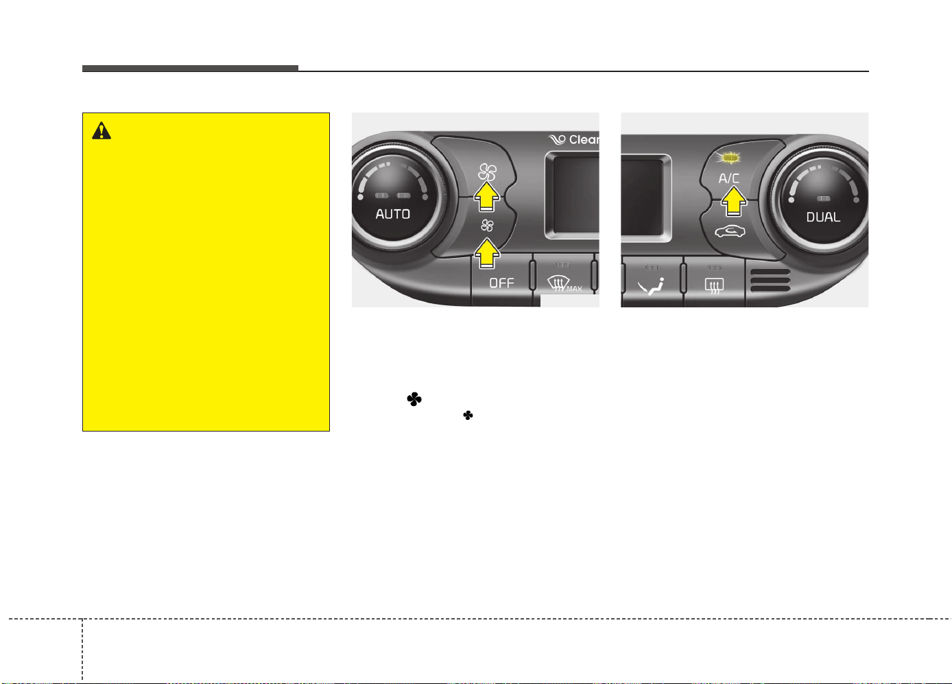
Features of your vehicle
1564
Fan speed control
The fan speed can be set to the desired
speed by pressing the fan speed control
button.
To change the fan speed, press the upper
button ( ) for higher speed, or press
the lower button ( ) for lower speed.
Pressing the OFF button turns off the
fan.
Air conditioning (if equipped)
Press the A/C button to turn the air con-
ditioning system on (indicator light will
illuminate).
Press the button again to turn the air
conditioning system off.
OJD042114
OJD042115
WARNING
• The continuous use of recirculat-
ed air in the climate control sys-
tem may increase humidity inside
the vehicle, causing the glass to
fog and obscuring visibility.
• Do not sleep in a vehicle with the
air conditioning or heating system
on. It may cause serious harm or
death due to a drop in the oxygen
level and/or body temperature.
• The continuous use of recirculat-
ed air in the climate control sys-
tem can produce drowsiness or
sleepiness, which may result in a
loss of vehicle control. Set the air
intake control to the outside
(fresh) air position as much as
possible while driving.
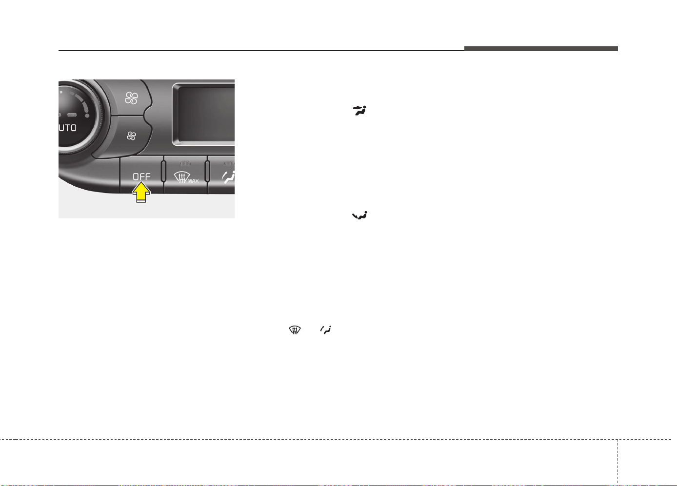
4157
Features of your vehicle
OFF mode
Press the OFF button to turn off the air
climate control system. However, you can
still operate the air intake buttons as long
as the ignition switch is in the ON posi-
tion.
System operation
Ventilation
1. Set the mode to the position.
2. Set the air intake control to the outside
(fresh) air position.
3. Set the temperature control to the
desired position.
4. Set the fan speed control to the
desired speed.
Heating
1. Set the mode to the position.
2. Set the air intake control to the outside
(fresh) air position.
3. Set the temperature control to the
desired position.
4. Set the fan speed control to the
desired speed.
5. If dehumidified heating is desired, turn
the air conditioning system on.
• If the windshield fogs up, set the mode
to the
or position.
Operation Tips
• To keep dust or unpleasant fumes from
entering the vehicle through the venti-
lation system, temporarily set the air
intake control to the recirculated air
position. Be sure to return the control
to the fresh air position when the irrita-
tion has passed to keep fresh air in the
vehicle. This will help keep the driver
alert and comfortable.
• Air for the heating/cooling system is
drawn in through the grilles just ahead
of the windshield. Care should be
taken that these are not blocked by
leaves, snow, ice or other obstructions.
• To prevent interior fog on the wind-
shield, set the air intake control to the
fresh air position and fan speed to the
desired position, turn on the air condi-
tioning system, and adjust the temper-
ature control to desired temperature.
OJD042118

Features of your vehicle
1584
Air conditioning (if equipped)
Kia Air Conditioning Systems are filled
with environmentally friendly refrigerant*.
1. Start the engine. Push the air condi-
tioning button.
2. Set the mode to the position.
3. Set the air intake control to the outside
air or recirculated air position.
4. Adjust the fan speed control and tem-
perature control to maintain maximum
comfort.
*: Your vehicle is filled with R-134a or R-
1234yf according to the regulation in
your country at the time of producing.
You can find out which air conditioning
refrigerant is applied to your vehicle at
the label inside of hood. Refer to chap-
ter 8 for more detail location of air con-
ditioning refrigerant label.
✽✽
NOTICE
• When using the air conditioning sys-
tem, monitor the temperature gauge
closely while driving up hills or in
heavy traffic when outside tempera-
tures are high. Air conditioning sys-
tem operation may cause engine over-
heating. Continue to use the blower
fan but turn the air conditioning sys-
tem off if the temperature gauge indi-
cates engine overheating.
• When opening the windows in humid
weather air conditioning may create
water droplets inside the vehicle.
Since excessive water droplets may
cause damage to electrical equipment,
air conditioning should only be used
with the windows closed.
CAUTION
• The refrigerant system should
only be serviced by trained and
certified technicians to insure
proper and safe operation.
• The refrigerant system should be
serviced in a well-ventilated place.
• The air conditioning evaporator
(cooling coil) shall never be
repaired or replaced with one
removed from a used or salvaged
vehicle and new replacement
MAC evaporators shall be certi-
fied (and labeled) as meeting SAE
Standard J2842.

4159
Features of your vehicle
Air conditioning system operation tips
• If the vehicle has been parked in direct
sunlight during hot weather, open the
windows for a short time to let the hot
air inside the vehicle escape.
• Use air conditioning to reduce humidi-
ty and moisture inside the vehicle on
rainy or humid days.
• During air conditioning system opera-
tion, you may occasionally notice a
slight change in engine speed as the
air conditioning compressor cycles.
This is a normal system operation
characteristic.
• Use the air conditioning system every
month only for a few minutes to ensure
maximum system performance.
• When using the air conditioning sys-
tem, you may notice clear water drip-
ping (or even puddling) on the ground
under the passenger side of the vehi-
cle. This is a normal system operation
characteristic.
• Operating the air conditioning system
in the recirculated air position provides
maximum cooling, however, continual
operation in this mode may cause the
air inside the vehicle to become stale.
• During cooling operation, you may
occasionally notice a misty air flow
because of rapid cooling and humid air
intake. This is a normal system opera-
tion characteristic.
Climate control air filter
The climate control air filter installed
behind the glove box filters the dust or
other pollutants that come into the vehi-
cle from the outside through the heating
and air conditioning system. If dust or
other pollutants accumulate in the filter
over a period of time, the air flow from the
air vents may decrease, resulting in
moisture accumulation on the inside of
the windshield even when the outside
(fresh) air position is selected. If this hap-
pens, we recommend that the climate
control air filter be replaced by an author-
ized Kia dealer.
1LDA5047
Outside air
Recirculated
air
Climate control
air filter
Blower
Evaporator
core
Heater core

Features of your vehicle
1604
✽✽
NOTICE
• Replace the filter according to the
Maintenance Schedule.
If the car is being driven in severe
conditions such as dusty, rough roads,
more frequent climate control air fil-
ter inspections and changes are
required.
• When the air flow rate suddenly
decreases, we recommend that the
system be checked by an authorized
Kia dealer.
Checking the amount of air con-
ditioner refrigerant and compres-
sor lubricant
When the amount of refrigerant is low,
the performance of the air conditioning is
reduced. Overfilling also has a bad influ-
ence on the air conditioning system.
Therefore, if abnormal operation is
found, we recommend that the system be
inspected by an authorized Kia dealer.
*: Your vehicle is filled with R-134a or R-
1234yf according to the regulation in
your country at the time of producing.
You can find out which air conditioning
refrigerant is applied your vehicle at
the label inside of hood. Refer to chap-
ter 8 for more detail location of air con-
ditioning refrigerant label.
WARNING - Vehicles
equipped with R-1234yf*
Because the refrigerant
is mildly inflammable
and at very high pres-
sure, the air conditioning
system should only be
serviced by trained and
certified technicians. It is
important that the cor-
rect type and amount of
oil and refrigerant is used.
Otherwise, it may cause damage to
the vehicle and personal injury.
WARNING - Vehicles
equipped with R-134a*
Because the refrigerant
is at very high pressure,
the air conditioning sys-
tem should only be
serviced by trained and
certified technicians. It is important
that the correct type and amount of
oil and refrigerant is used.
Otherwise, it may cause damage to
the vehicle and personal injury.
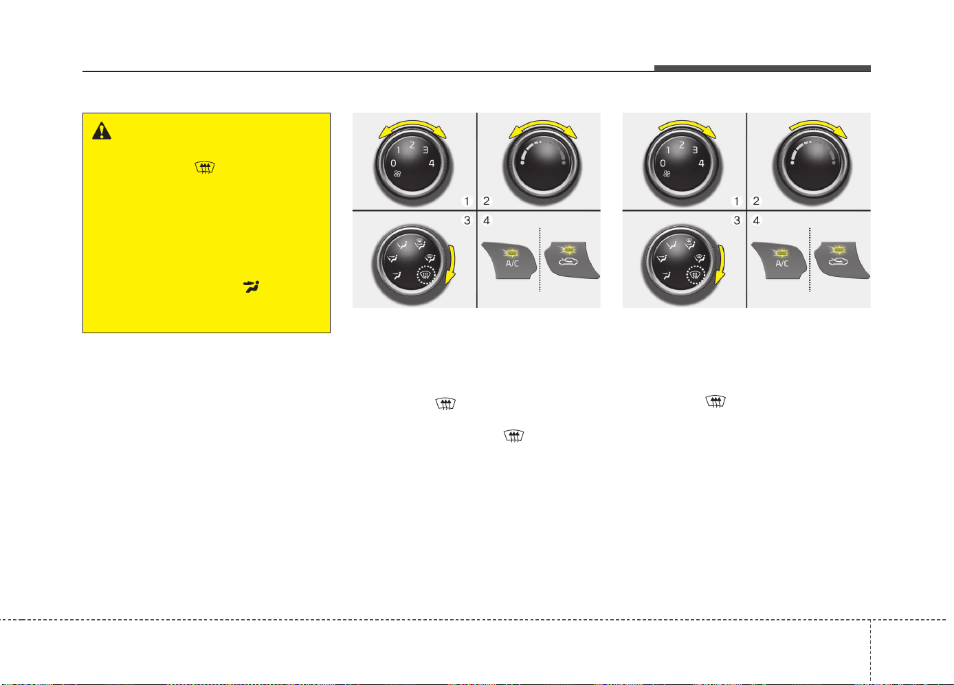
4161
Features of your vehicle
• For maximum defrosting, set the tem-
perature control to the hottest position
and the fan speed control to the high-
est speed.
• If warm air to the floor is desired while
defrosting or defogging, set the mode
to the floor-defrost position.
• Before driving, clear all snow and ice
from the windshield, rear window, out-
side rear view mirrors, and all side win-
dows.
• Clear all snow and ice from the hood
and air inlet in the cowl grill to improve
heater and defroster efficiency and to
reduce the probability of fogging up the
inside of the windshield.
Manual climate control system
To defog inside windshield
1. Set the fan speed to the desired posi-
tion.
2. Select desired temperature.
3. Select the position.
4. The outside (fresh) air will be selected
automatically. If the position is
selected, air conditioning (if equipped)
will also be selected automatically.
If the air conditioning and/or outside
(fresh) air position are not selected auto-
matically, press the corresponding button
manually.
To defrost outside windshield
1. Set the fan speed to the highest posi-
tion.
2. Set the temperature to the hottest
position.
3. Select the position.
4. The outside (fresh) air and air condi-
tioning will be selected automatically.
WINDSHIELD DEFROSTING AND DEFOGGING
WARNING - Windshield
heating
Do not use the position during
cooling operation in extremely
humid weather. The difference
between the temperature of the out-
side air and the windshield could
cause the outer surface of the
windshield to fog up, causing loss
of visibility. In this case, set the
mode selection to the position
and fan speed control to the lower
speed.
OJD042123 OJD042124
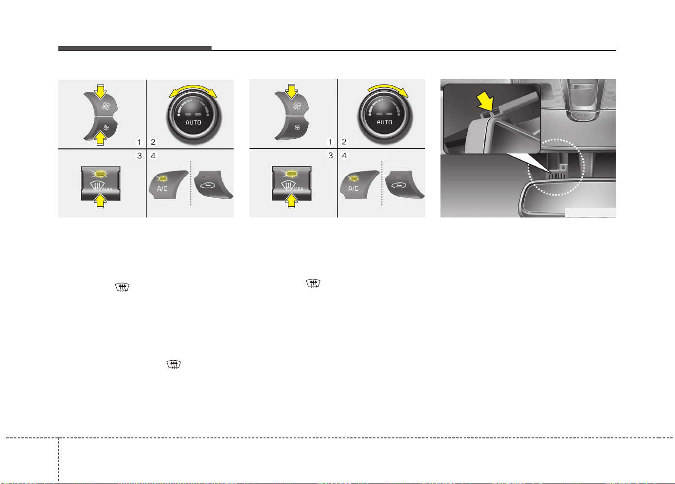
Features of your vehicle
1624
Automatic climate control system
To defog inside windshield
1. Set the fan speed to the desired
speed.
2. Select desired temperature.
3. Press the button.
4. The air conditioning will turn on
according to the detected ambient tem-
perature and outside (fresh) air posi-
tion will be selected automatically.
If the air conditioning is not selected
automatically, adjust the corresponding
button manually. If the position is
selected, lower fan speed is adjusted to a
higher fan speed.
To defrost outside windshield
1. Set the fan speed to the highest posi-
tion.
2. Set the temperature to the hottest
(HIGH) position.
3. Press the button.
4. The air conditioning will turn on
according to the detected ambient
temperature and outside (fresh) air
position will be selected automatically.
Auto defogging system
(Only for automatic climate control
system, if equipped)
Auto defogging reduces the possibility of
fogging up the inside of the windshield by
automatically sensing the moisture of
inside the windshield.
The auto defogging system operates
when the climate control system is on.
✽✽
NOTICE
The auto defogging system may not
operate normally, when the outside tem-
perture is below -15 °C.
OJD042125
OJD042126
OGDE041135
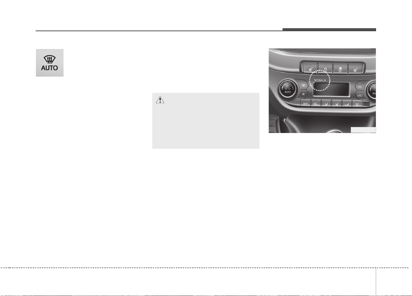
4163
Features of your vehicle
This indicator illuminates
when the auto defogging
system senses the moisture
of inside the windshield and
operates.
If more moisture is in the vehicle, higher
steps operate as follow.
Step 1 : Operating the air conditioning
Step 2 : Outside air position
Step 3 : Blowing air flow toward the wind-
shield
Step 4 : Increasing air flow toward the
windshield
If your vehicle is equipped with the auto
defogging system, it is automatically acti-
vated when the conditions are met.
However, if you would like to cancel the
auto defogging system, press the front
defroster button 4 times within 2 seconds
while pressing the AUTO button. The
indicator will blink 3 times to notify you
that the system is cancelled. To use the
auto defogging system again, follow the
procedures mentioned above.
If the battery has been disconnected or
discharged, it resets to the auto defog-
ging status.
✽✽
NOTICE
If the A/C off is manually selected while
the auto defogging system is on, the auto
defogging indicator will blink 3 times to
give notice that the A/C off can not be
selected.
When the ignition switch is in the ON
position, the clean air function turns on
automatically.
Also, the clean air function turns off auto-
matically, when the ignition switch turns
to the OFF position.
CAUTION
Do not remove the sensor cover
located on the upper end of the
driver side windshield glass.
Damage to the system parts could
occur and may not be covered by
your vehicle warranty.
OJD042129
CLEAN AIR (IF EQUIPPED)
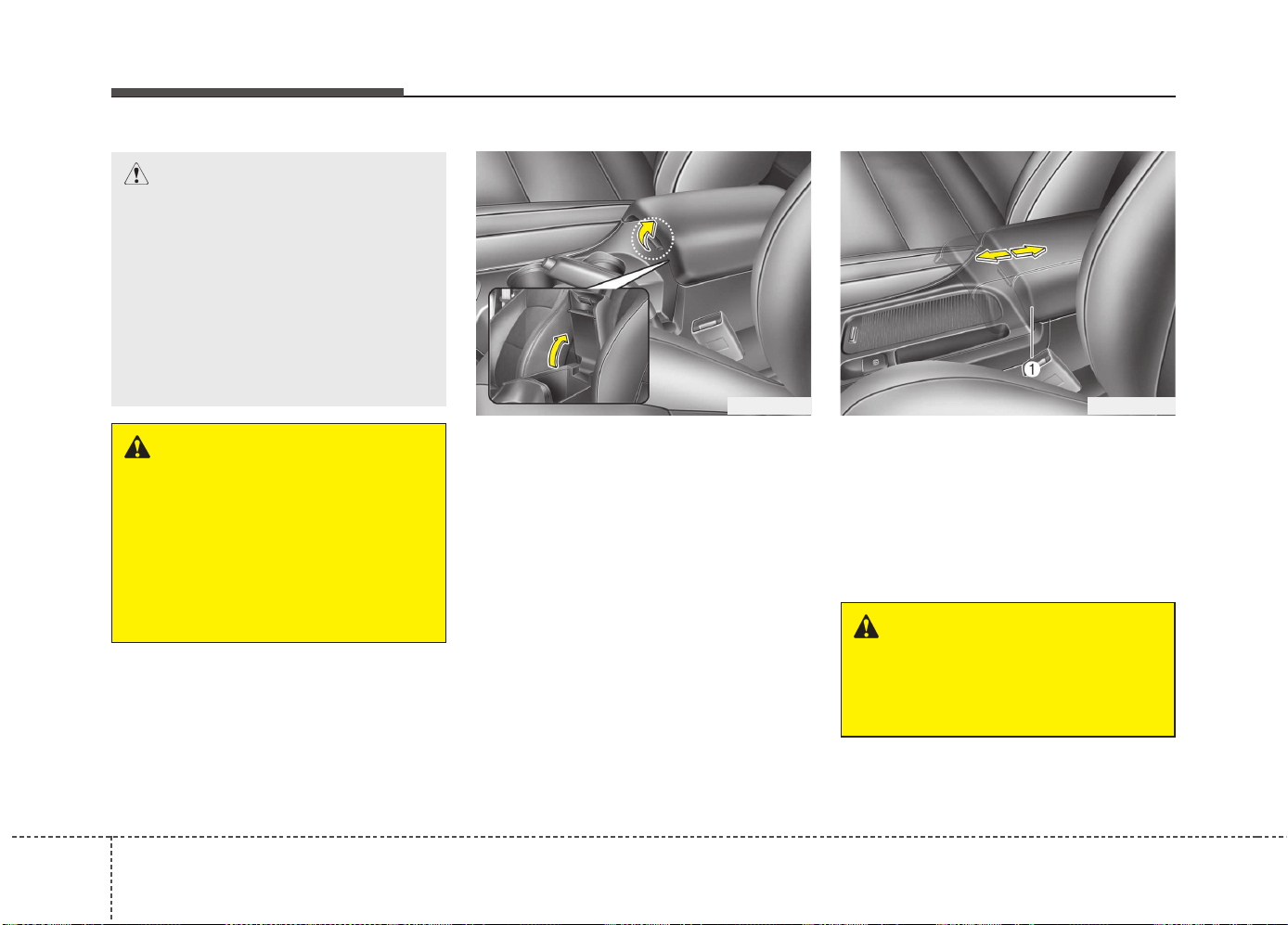
Features of your vehicle
1644
Center console storage
To open the center console storage, push
the lever and then lift up the cover.
Sliding armrest (if equipped)
To move forward
Grab the front portion of the armrest (1)
then pull it forward
To move rearward
Push the armrest rearward with your palm.
STORAGE COMPARTMENT
WARNING - Flammable
materials
Do not store cigarette lighters,
propane cylinders, or other flamma-
ble/explosive materials in the vehi-
cle. These items may catch fire
and/or explode if the vehicle is
exposed to hot temperatures for
extended periods.
CAUTION
• To avoid possible theft, do not
leave valuables in the storage
compartment.
• Always keep the storage com-
partment covers closed while
driving. Do not attempt to place
so many items in the storage
compartment that the storage
compartment cover can not close
securely.
OJD042130 OJD042131
WARNING
Do not grab the front portion of the
armrest (1) when moving the arm-
rest rearward. It may pinch your fin-
gers.
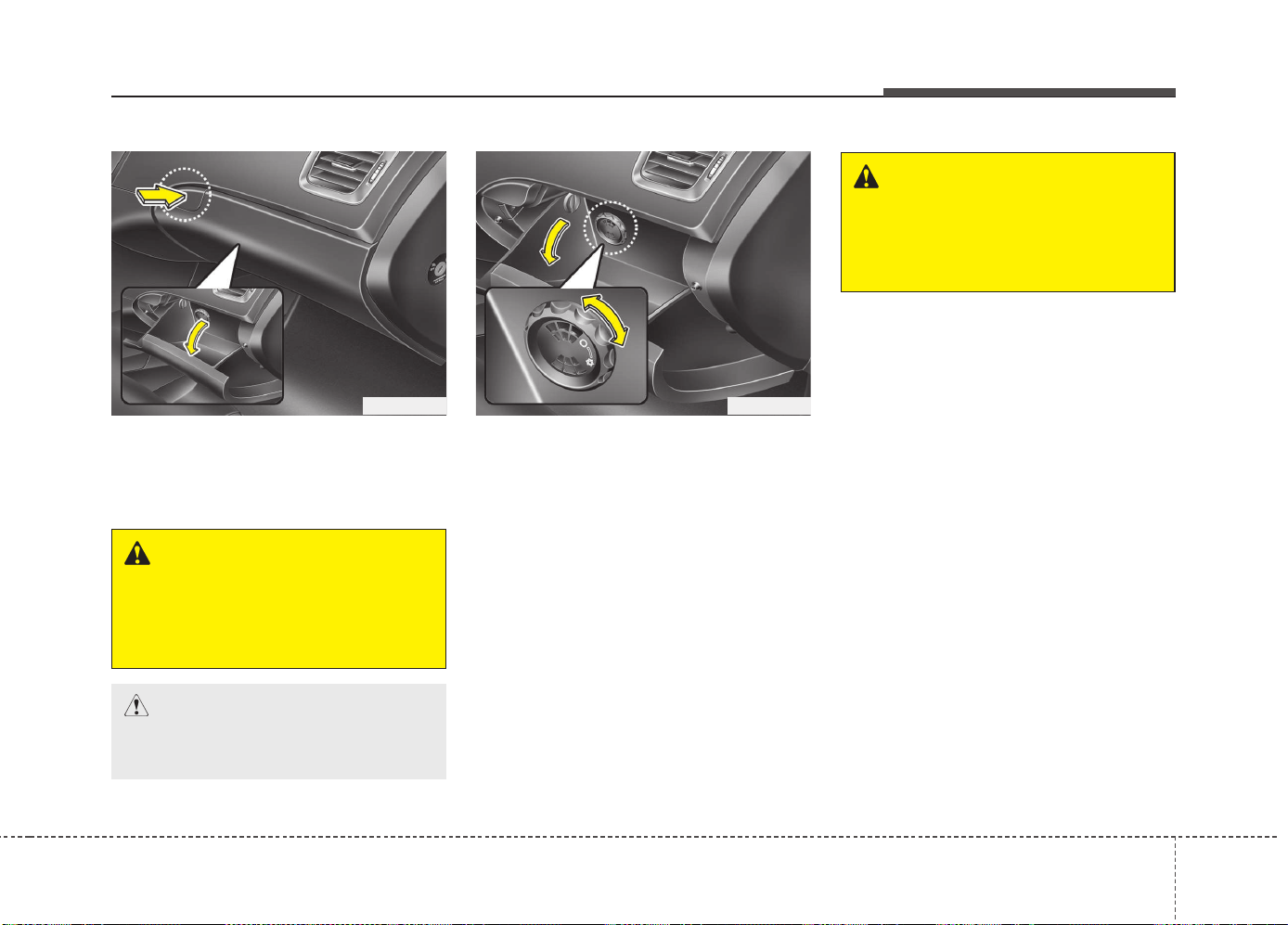
4165
Features of your vehicle
Glove box
To open the glove box, push the button
and the glove box will automatically
open. Close the glove box after use.
Cool box (if equipped)
You can keep beverage cans or other
items cool in the glove box.
1. Turn on the air conditioning. The tem-
perature of the cool box will change
according to the temperature of air
conditioning.
2. Turn the knob to the open position.
3. When the cool box is not used, turn the
knob to the close position.
✽✽
NOTICE
If some items in the cool box block the
vent, the cooling effectiveness of the cool
box is reduced.
OJD042133
WARNING
Do not put perishable food in the
cool box because it may not main-
tain the necessary consistent tem-
perature to keep the food fresh.
OJD042132
WARNING
To reduce the risk of injury in an
accident or sudden stop, always
keep the glove box door closed
while driving.
CAUTION
Do not keep food in the glove box
for a long time.
CC
CC
ll
ll
oo
oo
ss
ss
ee
ee
OO
OO
pp
pp
ee
ee
nn
nn
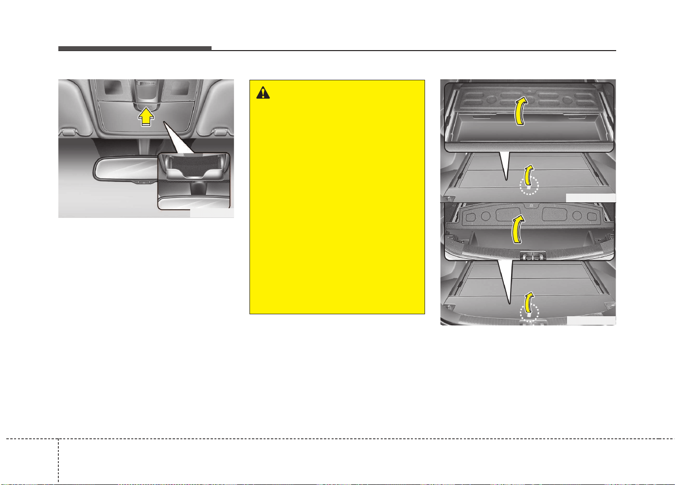
Features of your vehicle
1664
Sunglass holder
To open the sunglass holder, press the
cover and the holder will slowly open.
Place your sunglasses in the compart-
ment door with the lenses facing out.
Push to close.
Luggage tray (wagon)
You can place a first aid kit, a reflector tri-
angle (front tray), tools, etc. in the box for
easy access.
Grasp the handle on the top of the cover
and lift it.
OGD041139
WARNING
• Do not keep objects except sun-
glasses inside the sunglass hold-
er. Such objects can be thrown
from the holder in the event of a
sudden stop or an accident, pos-
sibly injuring the passengers in
the vehicle.
• Do not open the sunglasses hold-
er while the vehicle is moving.
The rear view mirror of the vehi-
cle can be blocked by an open
sunglass holder.
• Do not put the glasses forcibly
into a sunglass holder to prevent
breakage or deformation of
glasses. It may cause personal
injury if you try to open it forcibly
when the glasses are jammed in
holder.
OGDE042314
OGDE042313
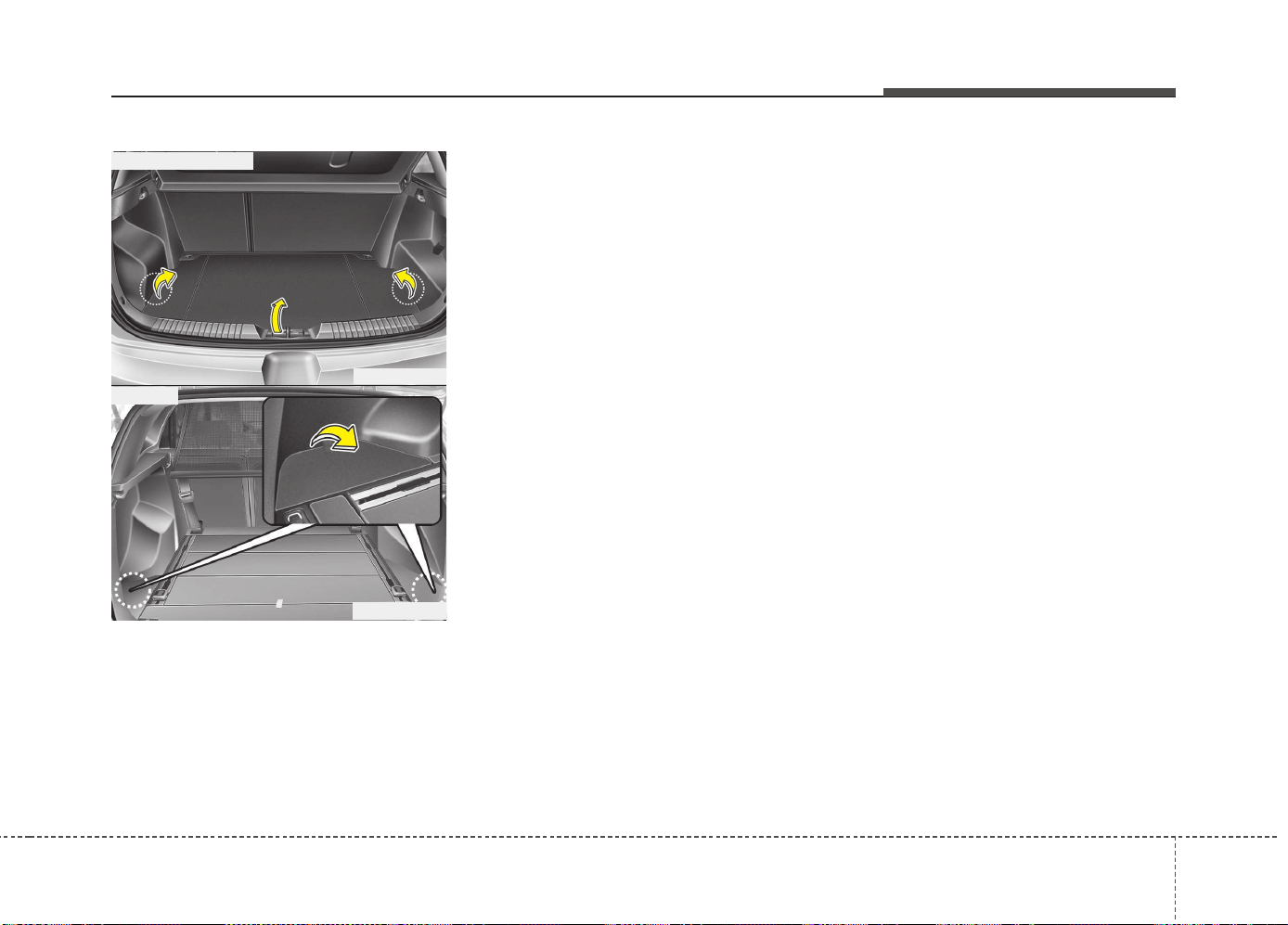
4167
Features of your vehicle
Luggage side tray (if equipped)
The luggage side tray can be used for
storing small items.
To open the cover, pull up the handle and
lift the cover.
OJD042153
OGDE042310
■ 3 Door and 5 Door
■ Wagon
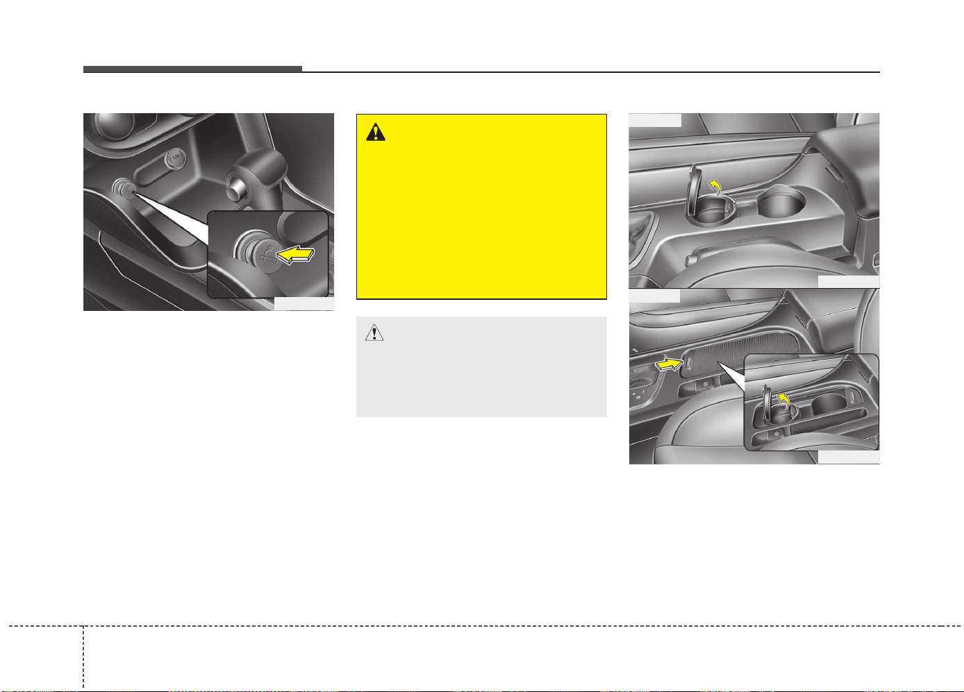
Features of your vehicle
1684
INTERIOR FEATURES
Cigarette lighter (if equipped)
For the cigarette lighter to work, the igni-
tion switch must be in the ACC position
or the ON position.
To use the cigarette lighter:
Push the lighter all the way into the socket.
When the element has heated, the lighter
will pop out to the "ready" position.
We recommend that you use parts for
replacement from an authorized Kia
dealer.
Ashtray (if equipped)
To use the ashtray, open the cover. (Type B)
To clean or empty the ashtray, pull it out.
OJD042134
CAUTION
The use of plug-in accessories
(shavers, hand-held vacuums, and
coffee pots, etc.) may damage the
socket or cause electrical failure.
WARNING
• Holding the lighter in after it is
heated will cause it to overheat.
• If the lighter does not pop out
within 30 seconds, remove it to
prevent overheating.
• Do not insert foreign objects into
the socket of the cigarette lighter.
It may damage the cigarette
lighter.
OJD042135
OJD042136
■ Type A
■ Type B
4169
Features of your vehicle
Cup holder
✽✽
NOTICE
• Keep your drinks sealed while driving
to prevent spilling your drink. If liq-
uid spills, it may get into the vehicle's
electrical/electronic system and dam-
age electrical/electronic parts.
• When cleaning spilled liquids, do not
dry the cup holder at high tempera-
ture. This may damage the cup holder.
WARNING - Ashtray use
• Do not use the vehicle’s ashtray
as a waste receptacle.
• Putting lit cigarettes or matches
in an ashtray with other com-
bustible materials may cause a
fire.
CAUTION
When cleaning spilled liquid, do not
dry the cup holder at high tempera-
tures. This may damage the chrome
part of the cup holder.
WARNING - Hot liquids
• Do not place uncovered cups of
hot liquid in the cup holder while
the vehicle is in motion. If the hot
liquid spills, you may burn your-
self. Such a burn to the driver
could lead to loss of control of
the vehicle.
• To reduce the risk of personal
injury in the event of sudden stop
or collision, do not place uncov-
ered or unsecured bottles, glass-
es, cans, etc., in the cup holder
while the vehicle is in motion.
WARNING
Keep cans and bottles out of direct
sunlight. Placing them in a hot vehi-
cle can cause them to explode.
CAUTION
Do not place uncovered cups in the
cup holder while the vehicle is in
motion. If the liquid spills, electric
systems may malfunction.
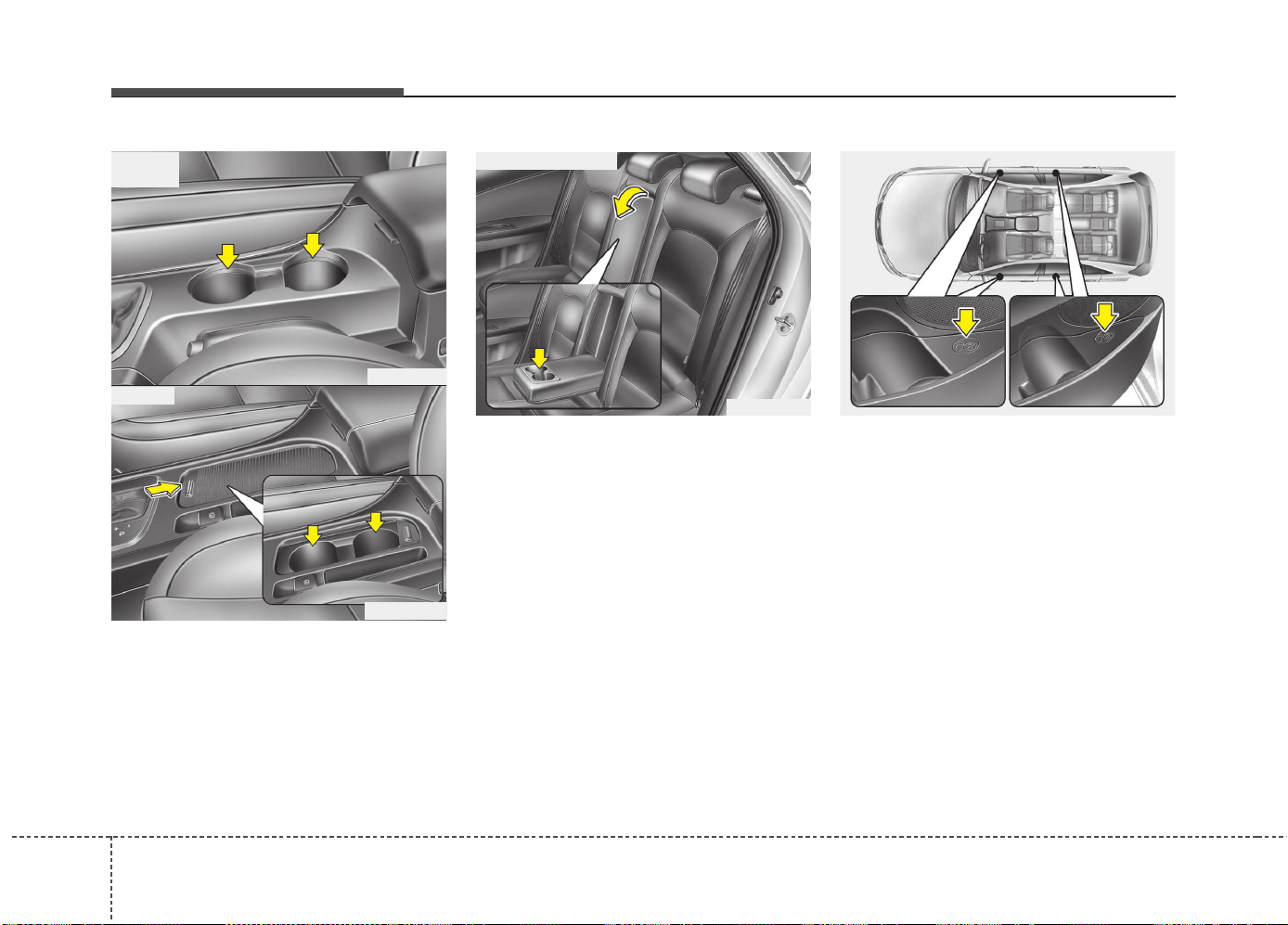
Features of your vehicle
1704
Cups or small beverage cans may be
placed in the cup holders.
Type B
To use the cup holder, open the cover.
Rear
To use the cup holder, pull down the arm-
rest.
Bottle holder
Bottles may be placed in the holder.
✽✽
NOTICE
Only bottles should be placed in the
holder as it is written in the vehicle
“BOTTLE ONLY”.
OJD042137
OJD042138
■ Front
• Type A
• Type B
OJD042139
■ Rear (if equipped)
OJD042162
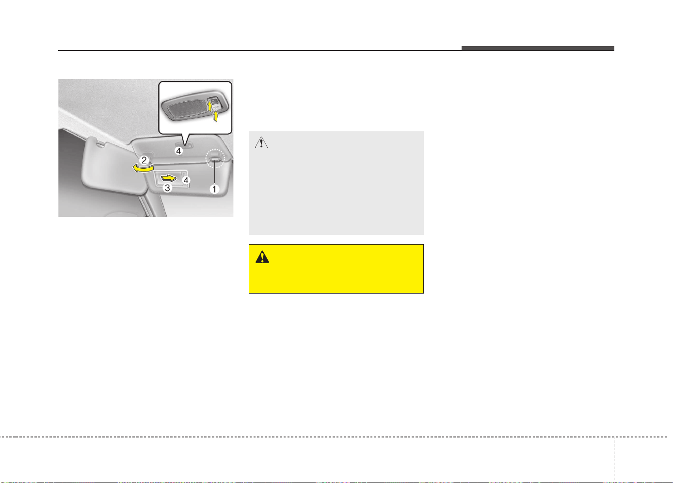
4171
Features of your vehicle
Sunvisor
Use the sunvisor to shield direct light
through the front or side windows.
To use a sunvisor, pull it downward.
To use a sunvisor for a side window, pull
it downward, unsnap it from the bracket
(1) and swing it to the side. (2)
To use the vanity mirror, pull down the
visor and open the mirror cover (3).
To use the vanity mirror lamp, switch it
on. (if equipped)
The ticket holder (4) is provided for hold-
ing a tollgate ticket. (if equipped)
✽✽
NOTICE
Close the vanity mirror cover securely
and return the sunvisor to its original
position after use.
❈ To learn how to use the vanity mirror
lamp, refer to "Interior light" in this
chapter.
OMD040167K
CAUTION - Vanity mirror
lamp (if equipped)
Always have the switch in the off
position when the vanity mirror
lamp is not in use. If the sunvisor is
closed without the lamp off, it may
discharge the battery or damage
the sunvisor.
WARNING
For your safety, do not obstruct your
vision when using the sunvisor.
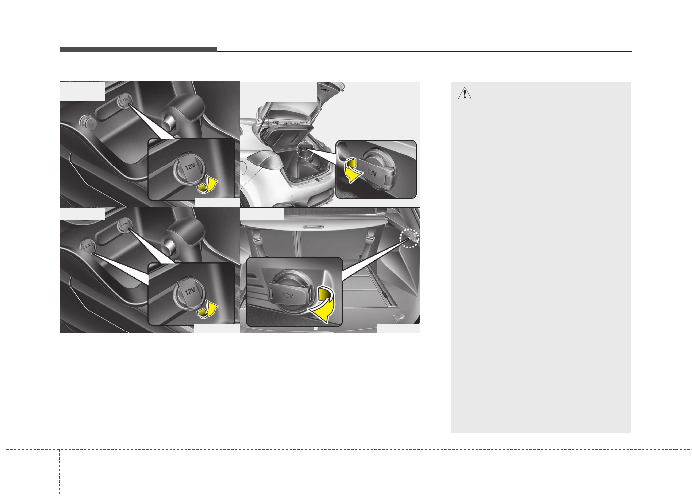
Features of your vehicle
1724
OJD042140
OJD042154
■ Front
• Type A
• Type B
OJD042155
OJD042243
■ Rear (if equipped)
• Type A
• Type B
Power outlet
The power outlet is designed to provide power for mobile telephones or other
devices designed to operate with vehicle electrical systems. The devices should
draw less than 10 amps with the engine running.
CAUTION
• Use power outlet only when the
engine is running and remove the
accessory plug after use. Using
the accessory plug for prolonged
periods of time with the engine
off could cause the battery to dis-
charge.
• Do not use an electric accessory
or equipment the power con-
sumption of which is greater than
12V (10A). It may cause damage
to the power outlet or vehicle
wiring harness.
• Only use 12V electric accessories
which are less than 10A in elec-
tric capacity.
• Adjust the air-conditioner or
heater to the lowest operating
level when using the power outlet.
• Close the cover when not in use.
• Some electronic devices can
cause electronic interference
when plugged into a vehicle’s
power outlet. These devices may
cause excessive audio static and
malfunctions in other electronic
systems or devices used in your
vehicle.
(Continued)
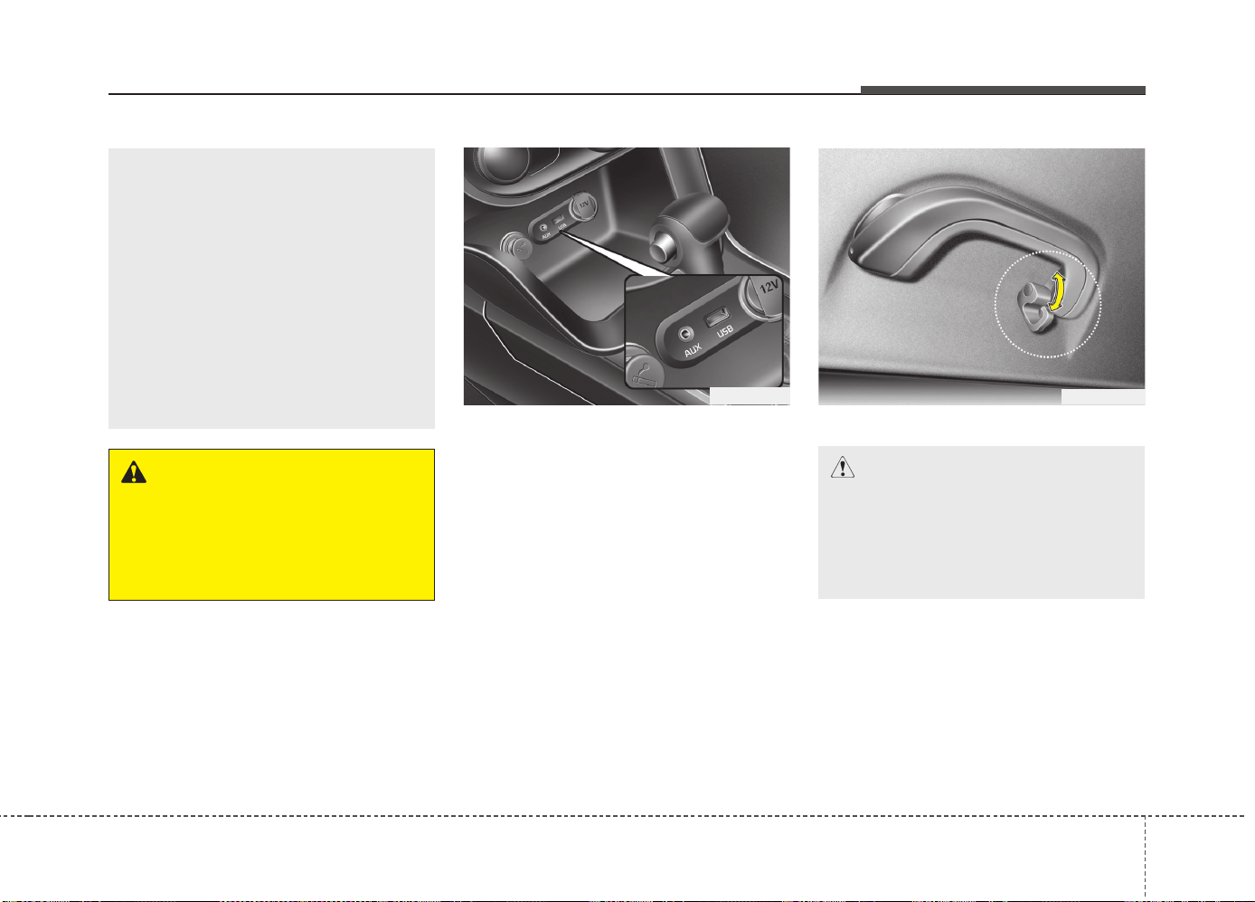
4173
Features of your vehicle
Aux, USB and iPod
®
You can use an aux port to connect audio
devices and an USB port to plug in an
USB and also an iPod
®
port to plug in an
iPod.
✽✽
NOTICE
When using a portable audio device
connected to the power outlet, noise may
occur during playback. If this happens,
use the power source of the portable
audio device.
❈ iPod
®
is a trademark of Apple Inc.
Clothes hanger
OJD042141
WARNING
Do not put a finger or a foreign ele-
ment (pin, etc.) into a power outlet
and do not touch with a wet hand.
You may get electrocuted or fire
may occur.
(Continued)
• Make sure that the electric
devices are plugged in securely. If
not, it could cause a malfunction
of electric systems.
• If you use an electric device with
a battery, electric current may
flow from the electric device into
the vehicle and may cause a mal-
function of electric systems. Only
use electric devices which could
prevent flowing of current into the
vehicle.
OED040354
CAUTION
• Do not hang heavy clothes, since
those may damage the hook.
• Be careful when opening and clos-
ing the doors. Clothes, etc. may
get caught between the door gap.
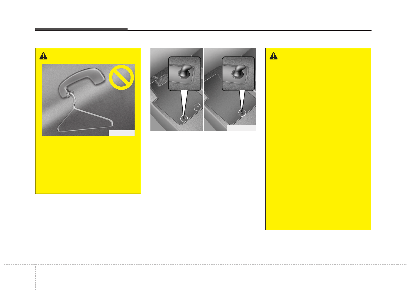
Features of your vehicle
1744
Floor mat anchor(s) (if equipped)
When using a floor mat on the front floor
carpet, make sure it attaches to the floor
mat anchor(s) in your vehicle. This keeps
the floor mat from sliding forward.
WARNING
The following must be observed
when installing ANY floor mat to
the vehicle.
• Ensure that the floor mats are
securely attached to the vehicle’s
floor mat anchor(s) before driving
the vehicle.
• Do not use ANY floor mat that
cannot be firmly attached to the
vehicle’s floor mat anchors.
• Do not stack floor mats on top of
one another (e.g. all-weather rub-
ber mat on top of a carpeted floor
mat). Only a single floor mat
should be installed in each posi-
tion.
IMPORTANT – Your vehicle was
manufactured with driver’s side
floor mat anchors that are
designed to securely hold the
floor mat in place. To avoid any
interference with pedal operation,
Kia recommends that the Kia
floor mat designed for use in your
vehicle be installed.
OGDE041219
■ Type A ■ Type B
WARNING
Do not hang other objects such as
hangers or hard objects except
clothes. Also, do not put heavy,
sharp or breakable objects in the
clothe pockets. In an accident or
when the curtain air bag is inflated,
it may cause vehicle damage or
personal injury.
OPS046500
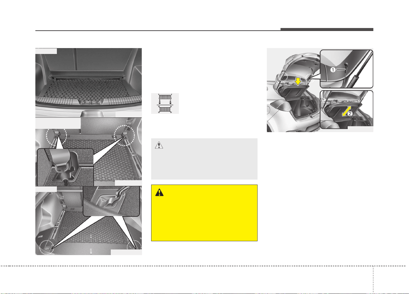
4175
Features of your vehicle
Luggage net (holder)
(if equipped)
To keep items from shifting in the cargo
area, you can use the four holders locat-
ed in the cargo area to attach the lug-
gage net.
This symbol indicates the
position of the front holders
(wagon).
If necessary, we recommend that you
contact an authorized Kia dealer.
Cargo area cover
(3 Door and 5 Door)
Use the cover to hide items stored in the
cargo area.
The cargo area cover will be lifted when
the tailgate is opened. Disconnect the
strap (1) from holder if you want to return
the cover to original position. To remove
the cargo area cover completely, lift the
cover to a 43-degree angle and pull it out
to the full (2). For installation of the cover,
reverse the removal procedure.
CAUTION
To prevent damage to the goods or
the vehicle, care should be taken
when carrying fragile or bulky
objects in the luggage compartment.
WARNING
To avoid eye injury, DO NOT over-
stretch the luggage net. ALWAYS
keep your face and body out of the
luggage net’s recoil path. DO NOT
use the luggage net when the strap
has visible signs of wear or damage.
OJD042150
OJD042152
OJD043051
■ Type A
■ Type B (for wagon)
• Front
OJD043502-1
• Rear
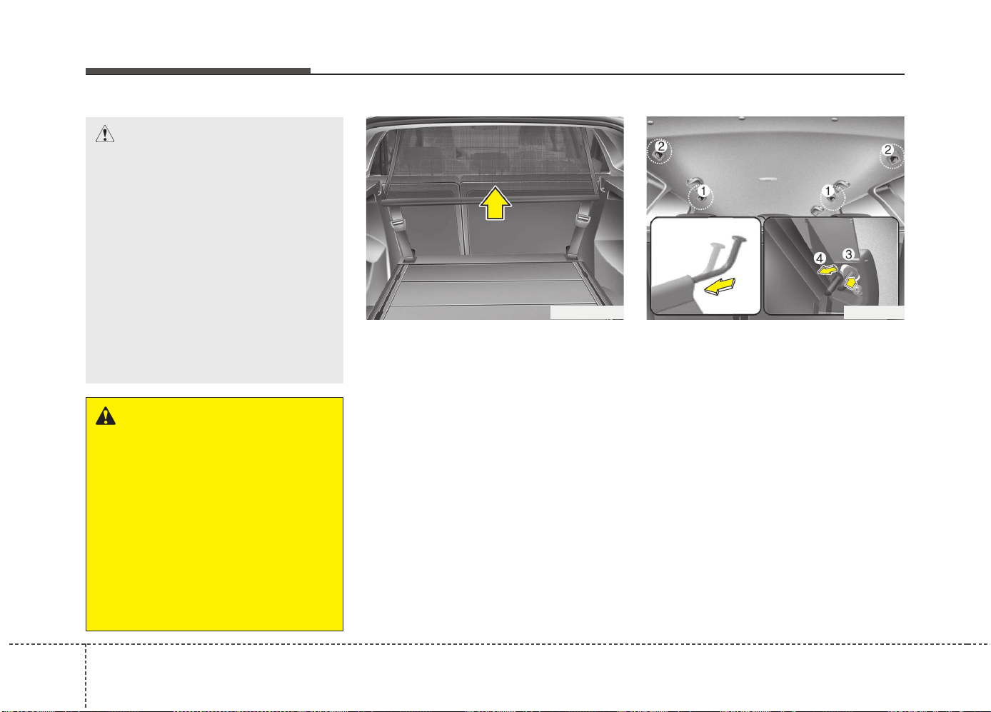
Features of your vehicle
1764
Barrier net (wagon) (if equipped)
Your vehicle is equipped with a barrier net.
When you load some cargoes on the rear
seat or rear cargo area, you must install
the barrier net behind front seatback or
rear seatback.
It is designed to help protect the heads of
the occupants by obstructing objects fly-
ing forward in frontal collisions.
There are eight hook holders on both
side of the headliner over the headrests
for upper side fixation and on the floor
behind the front seats or rear seats for
lower side fixation.
To install the barrier net
1. Open the cover (if equipped) for the
holder position (1) or (2) you want to
install.
2. Compress the one side net upper shaft
to length direction before insert the net
upper shaft into the large hole (3) and
then secure by sliding into the small
hole (4).
WARNING
• Do not place objects on the cargo
area cover while driving. Such
objects may be thrown about
inside the vehicle and possibly
injure vehicle occupants during
an accident or when braking.
• Never allow anyone to ride in the
luggage compartment. It is
designed for luggage only.
• Maintain the balance of the vehi-
cle and locate the weight as far
forward as possible.
OGDE042299 OJD043500
CAUTION
• When you return the cargo area
cover to its original position, hold
the cover and lower it.
• Do not operate the vehicle with
the cover removed. It may dam-
age to the cover.
• The cargo area cover may be lift-
ed when the tailgate is opened.
Ensure that the luggage on the
cover is moved to a safe place.
• Since the cargo area cover may be
damaged or malformed, do not
apply excessive force to the cover
or do not put the heavy loads on it.
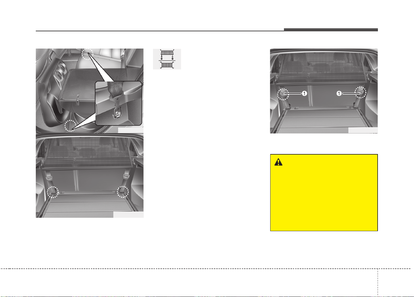
4177
Features of your vehicle
3. Hang the net strap hooks in the corre-
sponding hook holders on the floor
behind the front seat or rear seat.
This symbol indicates the
position of the hook holders
on the floor behind the rear
seat.
4. Fasten the straps, by using the
adjuster (1).
OJD032057
OGDE042302
OGDE042303
WARNING
• Make sure that there is no slack
in the barrier net by fastening the
strap securely when installing the
net. The strap should be fastened
after confirming that the hook is
inserted into the upper hook
holder securely.
• Make sure that the seatbacks are
locked securely.
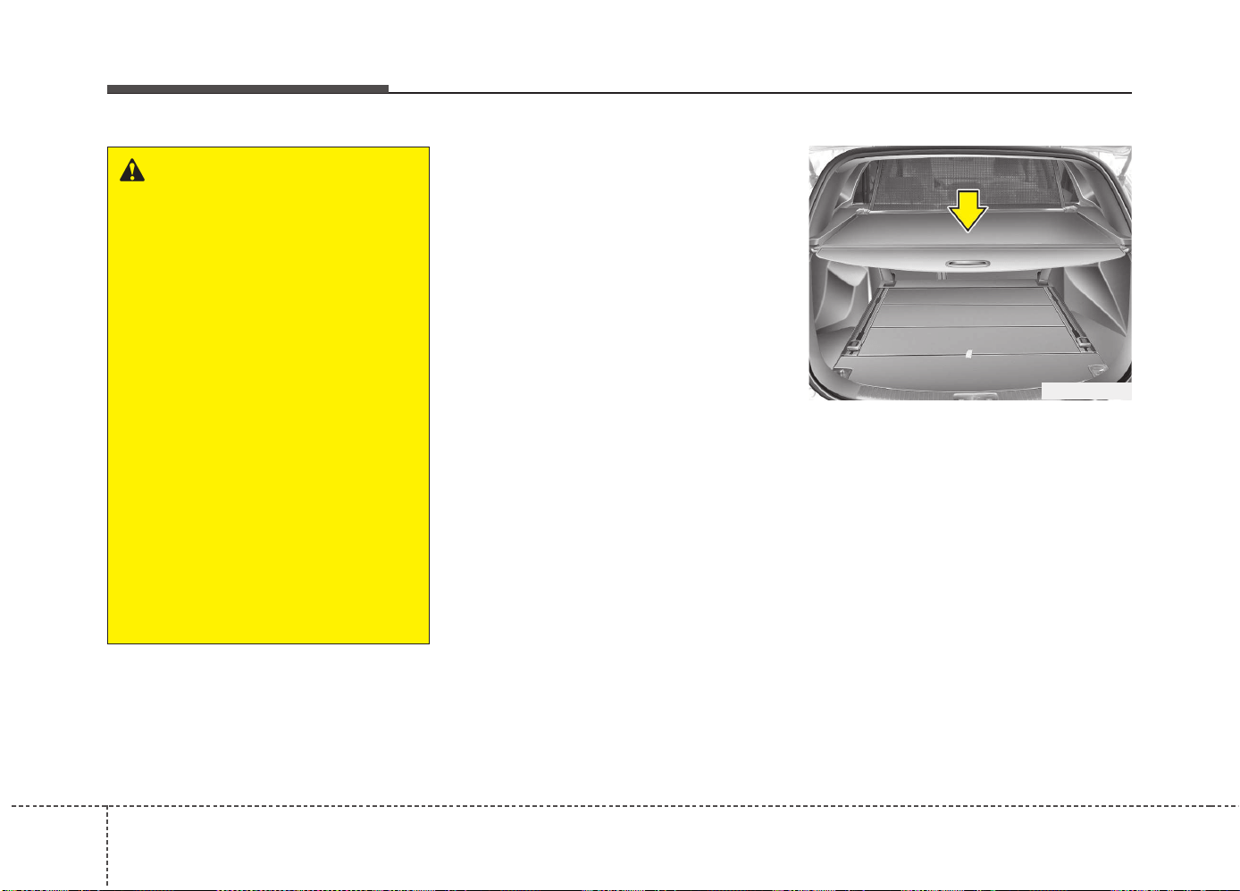
Features of your vehicle
1784
To remove the barrier net
1. Loosen the straps by using the strap
adjusters and remove the strap hooks
from the hook holders.
2. Remove the net upper shaft by pulling
it through the large holes.
3. Remove the barrier net.
Cargo security screen (wagon)
(if equipped)
Use the cargo security screen to hide
items stored in the cargo area.
WARNING
• Do not put passengers in the rear
seat or cargo area behind the bar-
rier net.
• Do not put passenger in the rear
centre seat when the barrier net
is installed behind the rear seats.
The barrier net may interfere with
use of the rear centre safety belt.
• Do not load cargo in the area
higher than the barrier net's
upper end.
• Do not load heavy cargo in the
area higher than the seatback to
avoid accident even if the barrier
net is installed.
• Do not load cargo which has
sharp edge that can pass through
the barrier net.
• Do not apply excessive force to
the barrier net by hanging on to
the net or by suspending heavy
cargo and so on.
OGDE042304
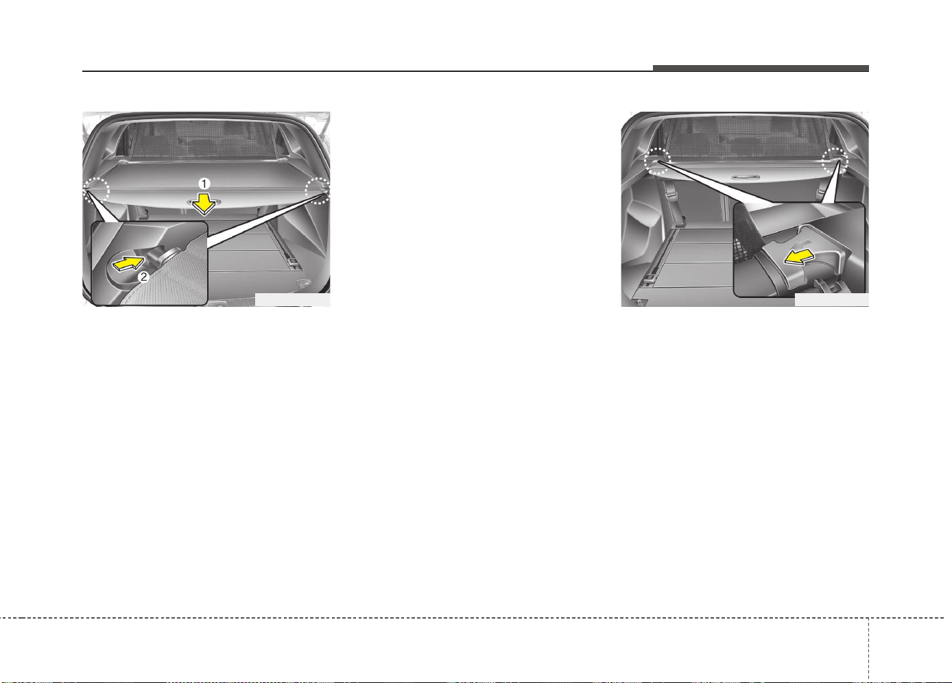
4179
Features of your vehicle
To use the cargo security screen
1. Pull the cargo security screen towards
the rear of the vehicle by the handle
(1).
2. Insert the guide pin into the guide (2).
✽✽
NOTICE
Pull out the cargo security screen with
the handle in the center to prevent the
guide pin from falling out of the guide.
When the cargo security screen is not in
use:
1. Pull the cargo security screen rear and
down to release it from the guides.
2. The cargo security screen will auto-
matically slide back in.
✽✽
NOTICE
The cargo security screen may not auto-
matically slide back in if the cargo secu-
rity screen is not fully pulled out. Fully
pull it out and then let go.
To remove the cargo security screen
1. Push the guide pin inward.
2. While pushing the guide pin, pull out
the cargo security screen.
OGDE042305 OGDE042306
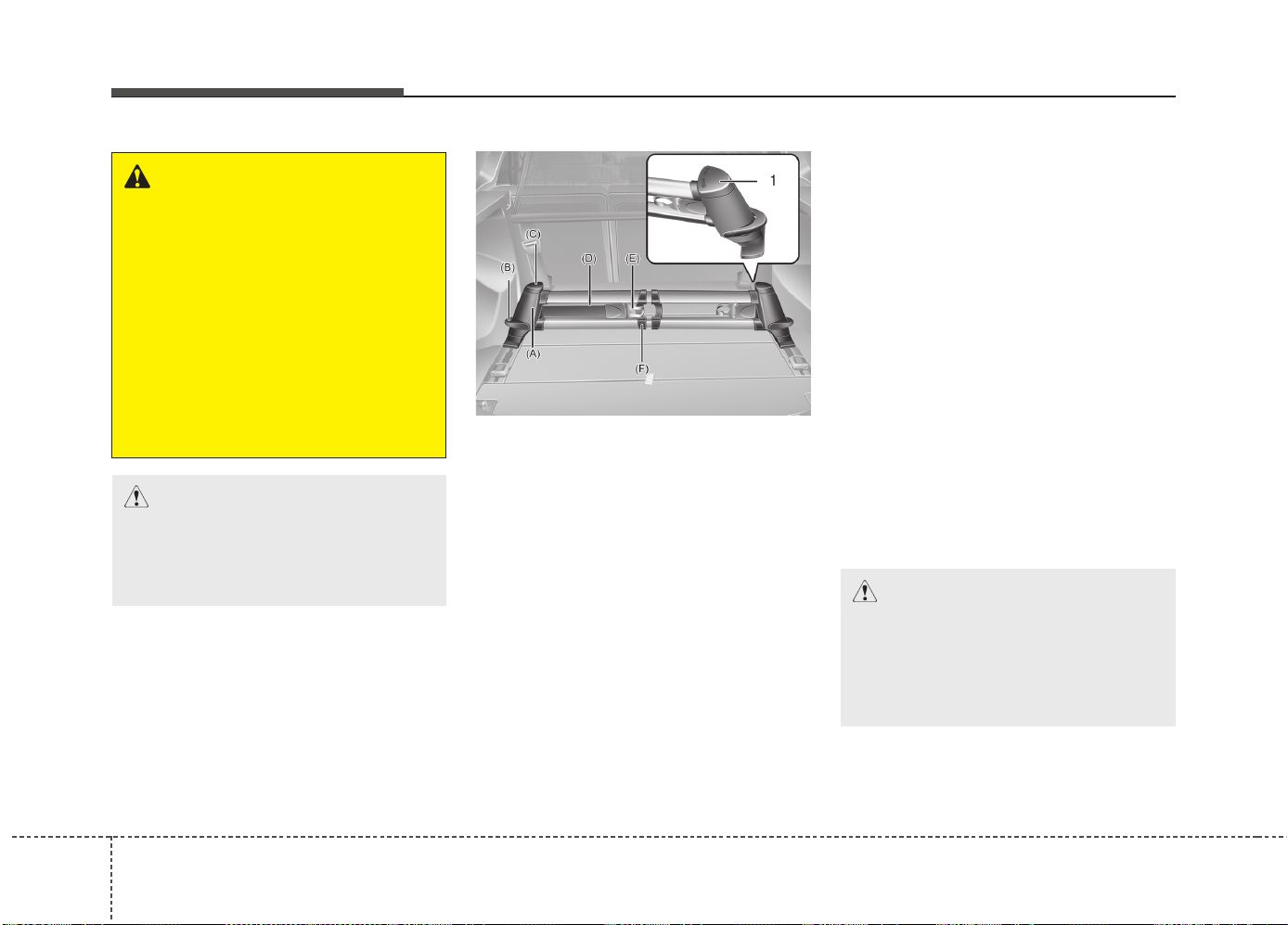
Features of your vehicle
1804
Luggage rail system (wagon)
(if equipped)
The luggage rail system may prevent the
luggage from sliding around in the lug-
gage compartment.
Build in segmentation bar
• Put both pillars (A) from the segmenta-
tion bar in the openings from the rail.
• To move the segmentation bar, put
your hand on the side of the pillar and
push down the lever arm (B).
• Make sure the pillars click into place.
• To release the belt, turn the upper ele-
ment (C) to the left or right until it clicks.
• Now you can pull the belt (D) and
secure your luggage by putting the belt
around the luggage and put the hook
(E) into the middle of the segmentation
bar (F).
• For bulky luggage, you can hook both
hooks into each other.
• To make sure the belt locks, put the
upper element (C) back into the lock
position (1).
WARNING
• Do not place objects on the cargo
security screen. Such objects
may be thrown about inside the
vehicle and possibly injure vehi-
cle occupants during an accident
or when braking.
• Never allow anyone to ride in the
luggage compartment. It is
designed for luggage only.
• Maintain the balance of the vehi-
cle and locate the weight as for-
ward as possible.
CAUTION
Since the cargo security screen
may be damaged or malformed, do
not put luggage on it when it is
used.
OGDE042307
CAUTION
• The segmentation bar must be
mounted and demounted with
both pillars simultaneously.
• Max. load: 30 kg with one belt
40 kg with two belts
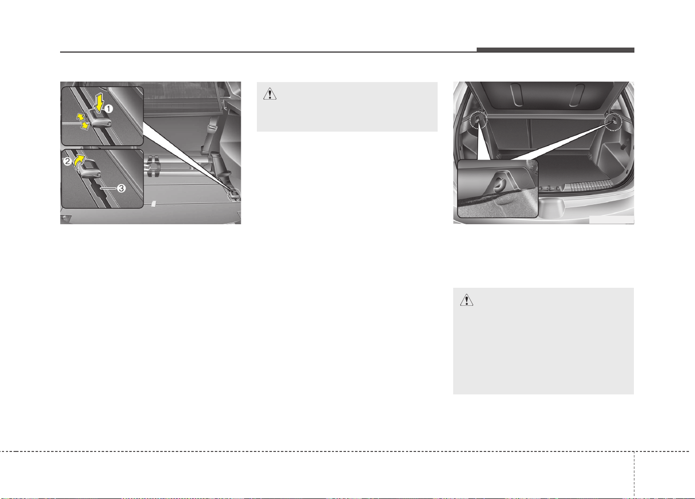
4181
Features of your vehicle
Applying the shackle on the guide rail
• Put the shackle (A) in the position
where the shackle is put in the rail.
• To move the shackle, press the button
(1) and move the shackle along the rail.
• Make sure the shackle is clicked into
place.
• To fix the luggage, pull up the hook (2)
in the middle cargo bay.
• Now you can mount e.g. belt to fix the
luggage in the hook.
• The shackle cannot be used in the
position where the shackle is put in and
out of the rail (3).
❈ The actual luggage room in the vehicle may
differ from the illustration.
Shopping bag holder
OGDE042308
CAUTION
• Do not hang a bag weighing more
than 3 kg (7 lbs.). It may cause
damage to the shopping bag
holder.
• Do not hang the frail objects
when you drive rough road, the
objects may be damaged.
OJD042151
CAUTION
Tensile force : max. 30 kgf. for
1 shackle
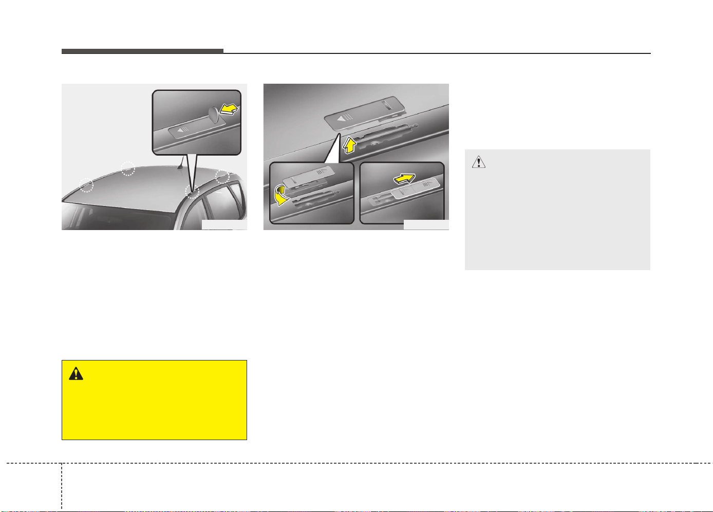
Features of your vehicle
1824
Mounting bracket for roof carrier
(if equipped)
To install or remove a roof carrier, you
can use the mounting bracket and cover
on the roof.
When you install a roof carrier, use the
following procedure.
1. Insert a slim tool(coin or flat blade driv-
er) into the slot and slide the cover
toward the arrow on the cover.
2. Rotate the cover half way and insert
the cover on the roof hole as the illus-
tration.
✽✽
NOTICE
To prevent loosing the roof carrier
cover, install the cover on the roof before
you install the roof carrier.
3. After using the roof carrier, install the
cover back on the roof in the reverse
order.
✽✽
NOTICE
If the vehicle is equipped with a sunroof,
be sure not to position cargo onto the
roof in such a way that it could interfere
with sunroof operation.
EXTERIOR FEATURES
OED046090 OED046091
WARNING
Use a coin or flat blade driver when
you remove the roof carrier cover.
If you use your fingernail, it may
damage your fingernail.
CAUTION
• When carrying cargo on the roof,
take the necessary precautions to
make sure the cargo does not
damage the roof of the vehicle.
• When carrying large objects on
the roof, make sure they do not
exceed the overall roof length or
width.
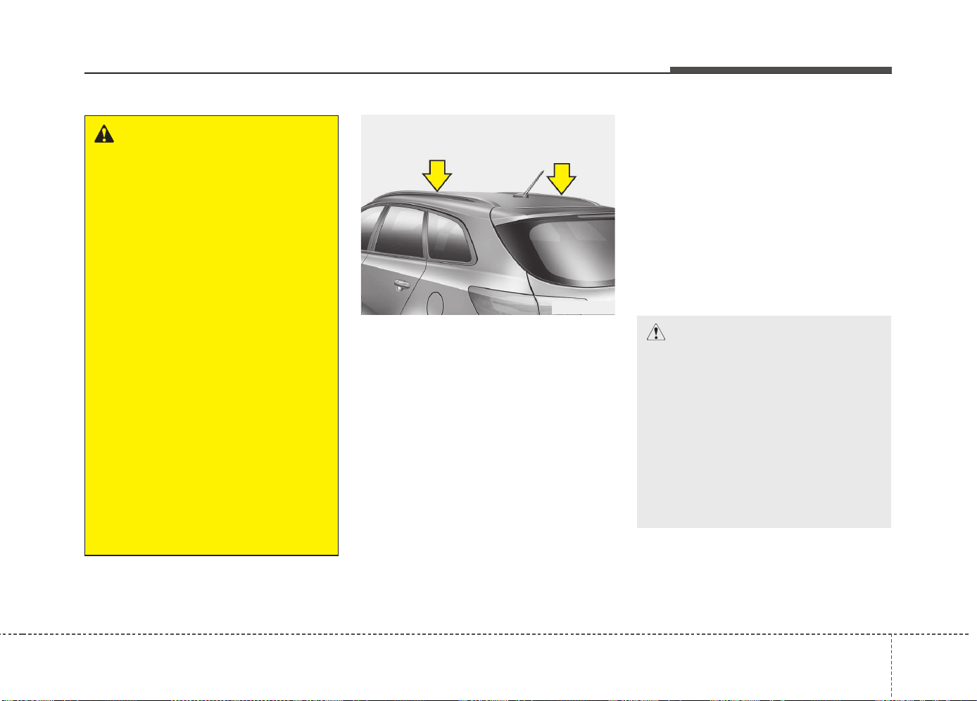
4183
Features of your vehicle
Roof rack (for wagon)
If the vehicle has a roof rack, you can
load cargo on top of your vehicle.
We recommend to obtain the crossbars
and fixing components needed to install
the roof rack on your vehicle from an
authorized Kia dealer.
✽✽
NOTICE
• The crossbars (if equipped) should be
placed in the proper load carrying
positions prior to placing items onto
the roof rack.
• If the vehicle is equipped with a sun-
roof, be sure not to position cargo onto
the roof rack in such a way that it
could
interfere with sunroof operation.
• When the roof rack is not being used to
carry cargo, the crossbars may need to
be repositioned if wind noise is detected.
WARNING
• The vehicle center of gravity will
be higher when items are loaded
onto the roof. Avoid sudden
starts, braking, sharp turns,
abrupt maneuvers or high speeds
that may result in loss of vehicle
control or rollover resulting in an
accident.
• Always drive slowly and turn cor-
ners carefully when carrying
items on the roof. Severe wind
updrafts, caused by passing
vehicles or natural causes, can
cause sudden upward pressure
on items loaded on the roof. This
is especially true when carrying
large, flat items such as wood
panels or mattresses. This could
cause the items to fall off the roof
and cause damage to your vehi-
cle or others around you.
• To prevent damage or loss of
cargo while driving, check fre-
quently before or while driving to
make sure the items on the roof
are securely fastened.
OJD042245
CAUTION
• When carrying cargo on the roof
rack, take the necessary precau-
tions to make sure the cargo does
not damage the roof of the vehicle.
• When carrying large objects on
the roof rack, make sure they do
not exceed the overall roof length
or width.
• When you are carrying cargo on
the roof rack, do not operate the
sunroof (if equipped).
(Continued)
• Always drive slowly and turn cor-
ners carefully when carrying
items on the roof rack. Severe
wind updrafts, caused by passing
vehicles or natural causes, can
cause sudden upward pressure
on items loaded on the roof rack.
This is especially true when car-
rying large, flat items such as
wood panels or mattresses. This
could cause the items to fall off
the roof rack and cause damage
to your vehicle or others around
you.
• To prevent damage or loss of
cargo while driving, check fre-
quently before or while driving to
make sure the items on the roof
rack are securely fastened.
WARNING
• The following specification is the
maximum weight that can be
loaded onto the roof rack.
Distribute the load as evenly as
possible across the crossbars (if
equipped) and roof rack and
secure the load firmly.
Loading cargo or luggage in
excess of the specified weight
limit on the roof rack may dam-
age your vehicle.
• The vehicle center of gravity will
be higher when items are loaded
onto the roof rack. Avoid sudden
starts, braking, sharp turns,
abrupt maneuvers or high speeds
that may result in loss of vehicle
control or rollover resulting in an
accident.
(Continued)
ROOF 100 kg (220 lbs.)
RACK EVENLY DISTRIBUTED
4184
Features of your vehicle
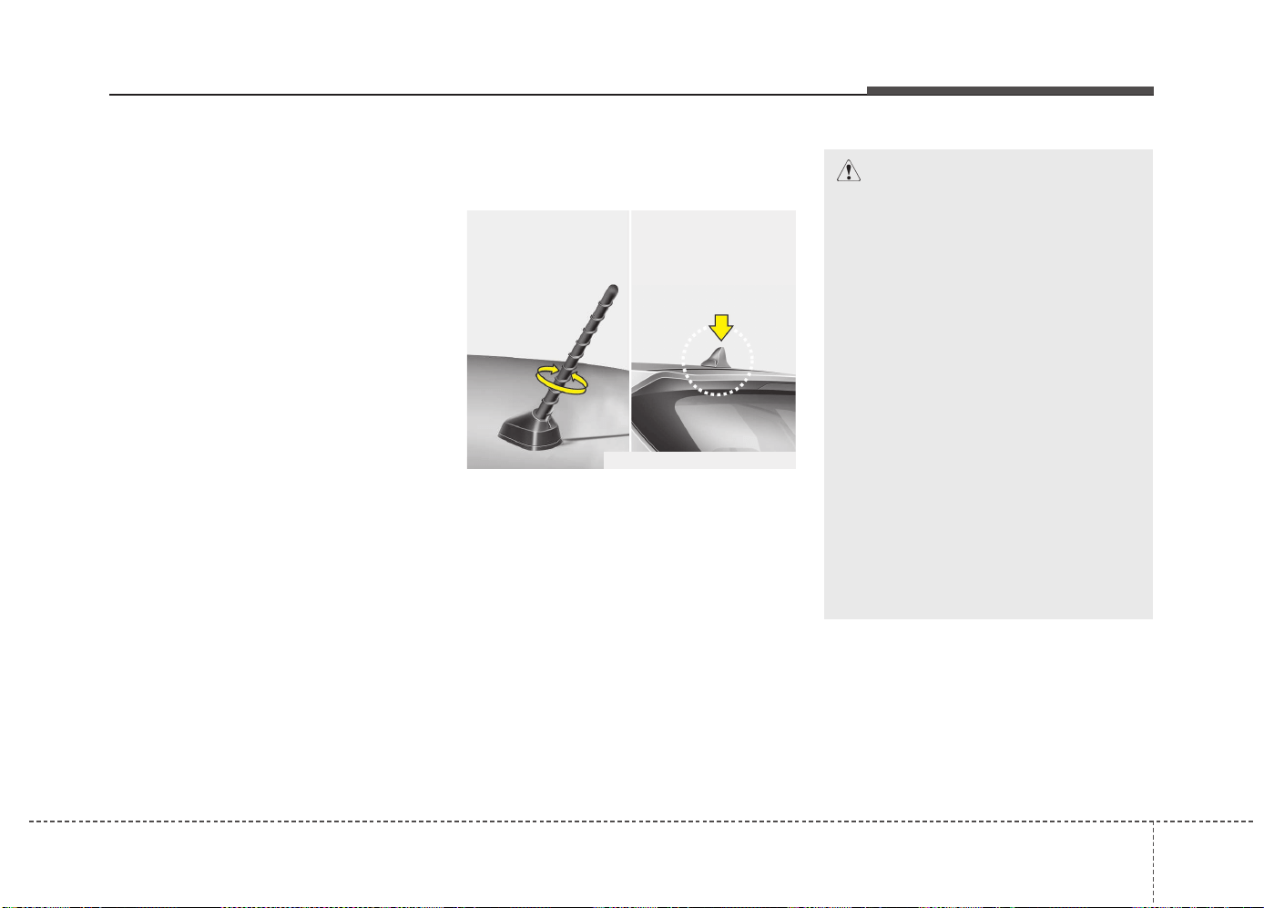
Features of your vehicle
AUDIO SYSTEM
4 185
✽✽
NOTICE
If you install an after market HID
head lamp, your vehicle’s audio and
electronic device may malfunction.
❈ If your vehicle is equipped with
AVN(Audio, Video and Navigation)
system, refer to a separately sup-
plied manual for detailed informa-
tion.
Antenna
Pole type antenna
Your vehicle uses a roof antenna to
receive both AM and FM broadcast
signals. This antenna pole is remov-
able. To remove the antenna pole,
turn it counterclockwise. To install the
antenna, turn it clockwise.
Shark fin antenna (If equipped)
The shark fin antenna will receive the
transmit data.
CAUTION - Pole type
antenna
• Before entering a place with a
low height clearance or a car
wash, remove the antenna
pole by rotating it counter-
clockwise. If not, the antenna
may be damaged.
• When reinstalling your anten-
na pole, it is important that it
is fully tightened and adjusted
to the upright position to
ensure proper reception. But it
could be removed when park-
ing the vehicle or when load-
ing cargo on the roof rack.
• When cargo is loaded on the
roof rack, do not place the
cargo near the antenna pole to
ensure proper reception.
OUM044339L/OANNMM2901
■ Type A ■ Type B
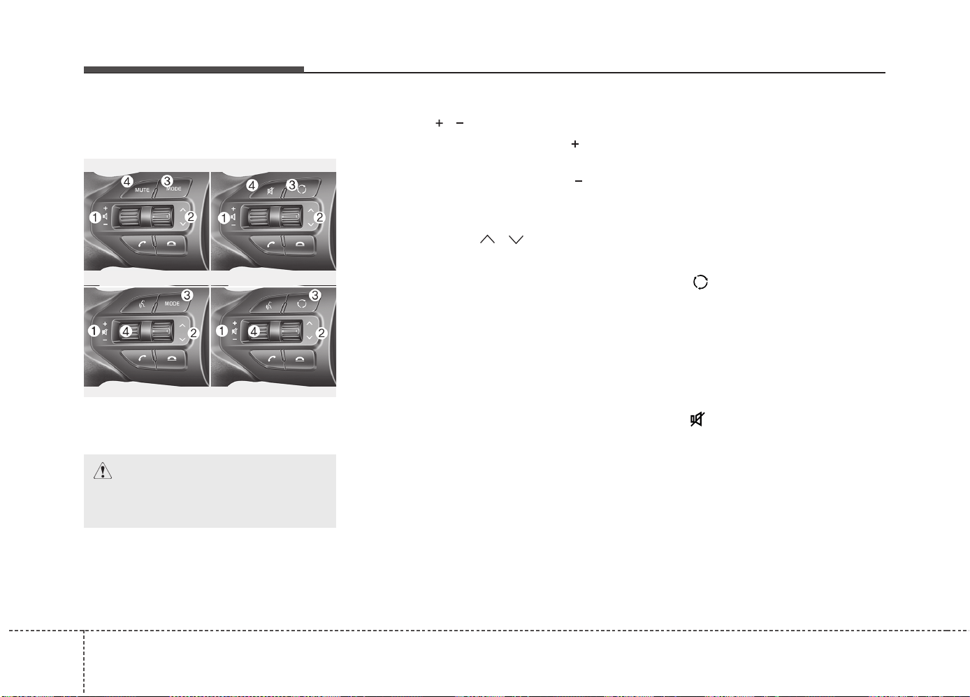
Features of your vehicle
1864
Steering wheel audio controls
(If equipped)
The steering wheel may incorporate
audio control buttons.
VOLUME ( / ) (1)
• Press the lever upward ( ) to
increase the volume.
• Press the lever downward ( ) to
decrease the volume.
SEEK/PRESET ( / ) (2)
The SEEK/PRESET lever has differ-
ent functions based on the system
mode. For the following functions the
lever should be pressed for 0.8 sec-
onds or more.
RADIO mode
It will function as the AUTO SEEK
select button.
CD/USB/iPod
®
mode
It will function as the FF/REW button.
If the SEEK/PRESET button is
pressed for less than 0.8 seconds, it
will work as follows in each mode.
RADIO mode
It will function as the PRESET STA-
TION buttons.
CD/USB/iPod
®
mode
It will function as TRACK UP/DOWN
button.
MODE ( ) (3)
Press the button to change audio
source.
FM ➟ AM ➟ CD ➟ USB/iPod
®
➟ AUX ➟
MY MUSIC ➟
Bluetooth
®
Wireless
Technology audio
MUTE ( ) (4, if equipped)
• Press the button to mute the
sound.
• Press the button to turn off the
microphone during a telephone
call.
Detailed information for audio control
buttons are described in the following
pages in this section.
CAUTION
Do not operate audio remote
control buttons simultaneously.
OUM044210L
■ Type A
■ Type B
■ Type C
■ Type D
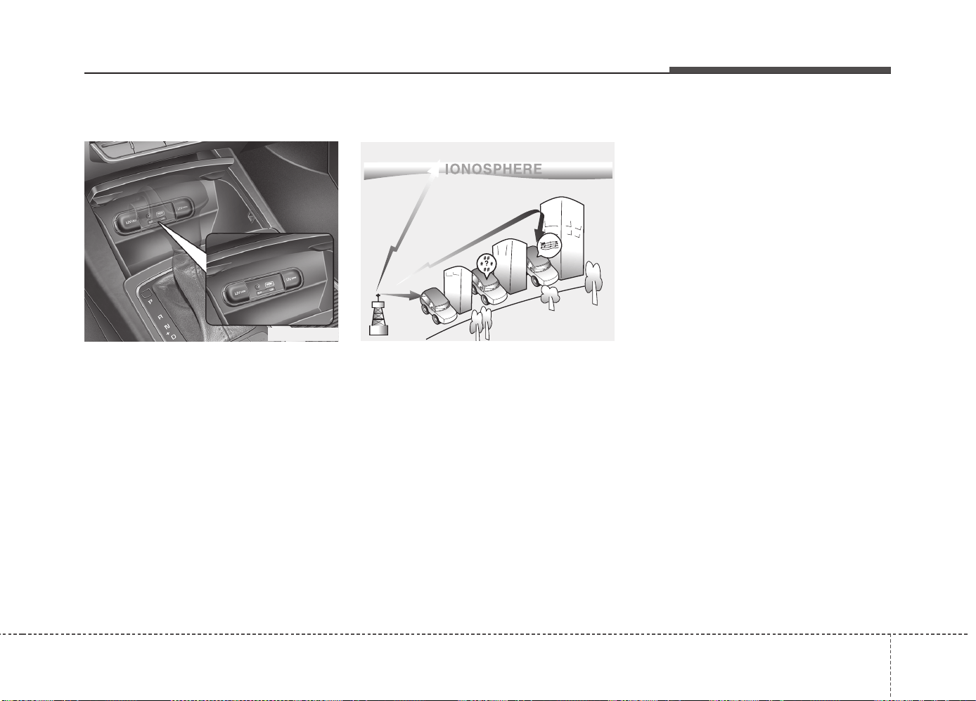
Features of your vehicle
4 187
AUX, USB and iPod
®
port
You can use an aux port to connect
audio devices and an USB port to
plug in an USB and also an iPod
®
port to plug in an iPod
®
.
✽✽
NOTICE
When using a portable audio device
connected to the power outlet, noise
may occur during playback. If this
happens, use the power source of the
portable audio device.
*
iPod
®
is a trademark of Apple Inc.
How Vehicle Audio Works
AM and FM radio signals are broad-
cast from transmitter towers located
around your city. They are intercept-
ed by the radio antenna on your vehi-
cle. This signal is then received by
the radio and sent to your vehicle
speakers.
When a strong radio signal has
reached your vehicle, the precise
engineering of your audio system
ensures the best possible quality
reproduction. However, in some
cases the signal coming to your vehi-
cle may not be strong and clear.
This can be due to factors, such as
the distance from the radio station,
closeness of other strong radio sta-
tions or the presence of buildings,
bridges or other large obstructions in
the area.
JBM001
FM reception
OUM044044L
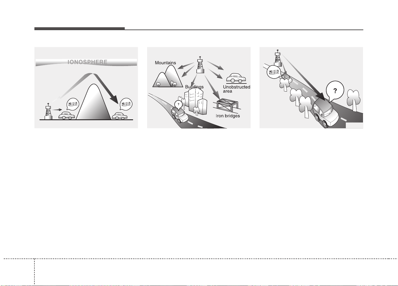
Features of your vehicle
1884
AM broadcasts can be received at
greater distances than FM broad-
casts. This is because AM radio
waves are transmitted at low fre-
quencies. These long, low frequency
radio waves can follow the curvature
of the earth rather than travelling
straight out into the atmosphere. In
addition, they curve around obstruc-
tions so that they can provide better
signal coverage.
FM broadcasts are transmitted at
high frequencies and do not bend to
follow the earth's surface. Because
of this, FM broadcasts generally
begin to fade at short distances from
the station. Also, FM signals are eas-
ily affected by buildings, mountains,
or other obstructions. These can
result in certain listening conditions
which might lead you to believe a
problem exists with your radio. The
following conditions are normal and
do not indicate radio trouble:
• Fading - As your vehicle moves
away from the radio station, the
signal will weaken and sound will
begin to fade. When this occurs,
we suggest that you select another
stronger station.
• Flutter/Static - Weak FM signals or
large obstructions between the
transmitter and your radio can dis-
turb the signal causing static or
fluttering noises to occur. Reducing
the treble level may lessen this
effect until the disturbance clears.
JBM004JBM002
AM (MW, LW) reception
JBM003
FM radio station
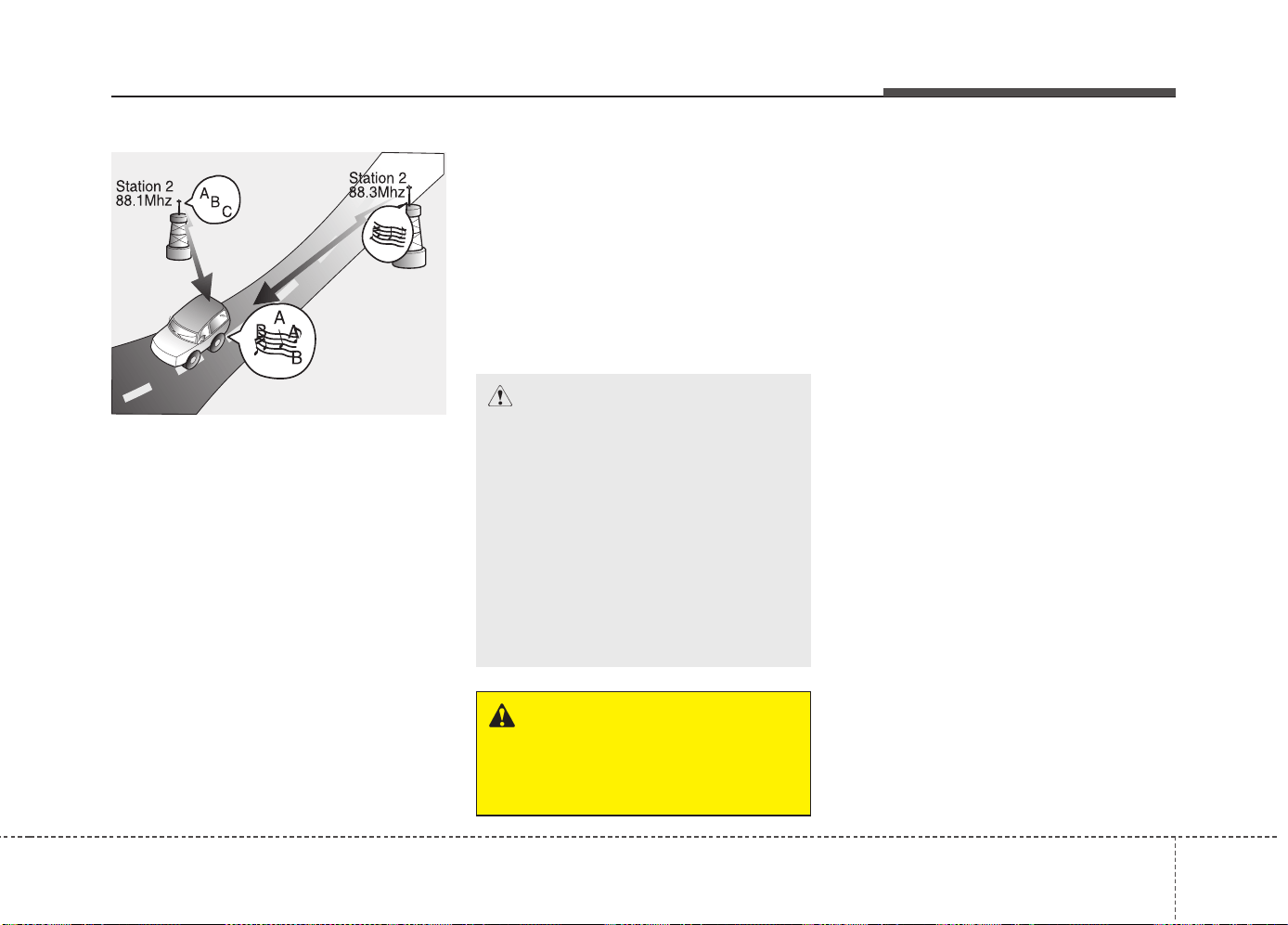
Features of your vehicle
4 189
• Station Swapping - As a FM signal
weakens, another more powerful
signal near the same frequency
may begin to play. This is because
your radio is designed to lock onto
the clearest signal. If this occurs,
select another station with a
stronger signal.
• Multi-Path Cancellation - Radio
signals being received from sever-
al directions can cause distortion
or fluttering. This can be caused by
a direct and reflected signal from
the same station, or by signals
from two stations with close fre-
quencies. If this occurs, select
another station until the condition
has passed.
Using a cellular phone or a two-
way radio
When a cellular phone is used inside
the vehicle, noise may be produced
from the audio system. This does not
mean that something is wrong with the
audio equipment. In such a case, use
the cellular phone at a place as far as
possible from the audio equipment.
Caring for Disc
• If the temperature inside the car is
too high, open the car windows to
ventilate before using the system.
• It is illegal to copy and use
MP3/WMA files without permis-
sion. Use CDs that are created
only by lawful means.
• Do not apply volatile agents, such
as benzene and thinner, normal
cleaners and magnetic sprays
made for analogue disc onto CDs.
• To prevent the disc surface from
getting damaged, hold CDs by the
edges or the center hole only.
• Clean the disc surface with a piece
of soft cloth before playback (wipe
it from the center to the outside
edge).
• Do not damage the disc surface or
attach pieces of sticky tape or
paper.
• Make certain only CDs are insert-
ed into the CD player (Do not insert
more than one CD at a time).
• Keep CDs in their cases after use
to protect them from scratches or
dirt.
CAUTION
When using a communication
system such as a cellular phone
or a radio set inside the vehicle,
a separate external antenna
must be fitted. When a cellular
phone or a radio set is used
with an internal antenna alone,
it may interfere with the vehi-
cle's electrical system and
adversely affect safe operation
of the vehicle.
WARNING
Do not use a cellular phone
while driving. Stop at a safe
location to use a cellular phone.
JBM005
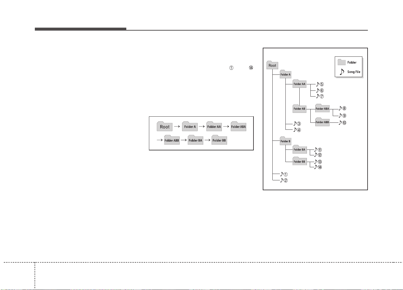
Features of your vehicle
1904
• Depending on the type of CD-
R/CD-RW CDs, certain CDs may
not operate normally according to
manufacturing companies or mak-
ing and recording methods. In such
circumstances, continued use may
cause malfunctions to your audio
system.
✽✽
NOTICE - Playing an
Incompatible Copy
Protected Audio CD
Some copy protected CDs, which do
not comply with international audio
CD standards (Red Book), may not
play on your car audio. Please note
that inabilities to properly play a
copy protected CD may indicate
that the CD is defective, not the CD
player.
NOTE:
Order of playing files (folders) :
1. Song playing order : to
sequentially.
2. Folder playing order :
❋ If no song file is contained in
the folder, that folder is not dis-
played.

Features of your vehicle
4 191
WARNING
• Do not stare at the screen
while driving. Staring at the
screen for prolonged periods
of time could lead to traffic
accidents.
• Do not disassemble, assem-
ble, or modify the audio sys-
tem. Such acts could result in
accidents, fire, or electric
shock.
• Using the phone while driving
may lead to a lack of attention
of traffic conditions and
increase the likelihood of
accidents. Use the phone fea-
ture after parking the vehicle.
(Continued)
(Continued)
• Heed caution not to spill water
or introduce foreign objects
into the device. Such acts
could lead to smoke, fire, or
product malfunction.
• Please refrain from use if the
screen is blank or no sound
can be heard as these signs
may indicate product malfunc-
tion. Continued use in such
conditions could lead to acci-
dents (fires, electric shock) or
product malfunctions.
• Do not touch the antenna dur-
ing thunder or lightening as
such acts may lead to light-
ning induced electric shock.
(Continued)
(Continued)
• Do not stop or park in park-
ing-restricted areas to operate
the product. Such acts could
lead to traffic accidents.
• Use the system with the vehi-
cle ignition turned on.
Prolonged use with the igni-
tion turned off could result in
battery discharge.

Features of your vehicle
1924
(Continued)
• If you want to change the posi-
tion of device installation,
please inquire with your place
of purchase or service mainte-
nance center. Technical expert-
ise is required to install or dis-
assemble the device.
• Turn on the car ignition before
using this device. Do not oper-
ate the audio system for long
periods of time with the igni-
tion turned off as such opera-
tions may lead to battery dis-
charge.
• Do not subject the device to
severe shock or impact. Direct
pressure onto the front side of
the monitor may cause damage
to the LCD or touch screen.
(Continued)
(Continued)
• When cleaning the device,
make sure to turn off the device
and use a dry and smooth
cloth. Never use tough materi-
als, chemical cloths, or sol-
vents (alcohol, benzene, thin-
ners, etc.) as such materials
may damage the device panel
or cause color/quality deterio-
ration
• Do not place beverages close
to the audio system. Spilling
beverages may lead to system
malfunction.
• In case of product malfunc-
tion, please contact your place
of purchase or After Service
center.
• Placing the audio system with-
in an electromagnetic environ-
ment may result in noise inter-
ference.
CAUTION
• Operating the device while
driving could lead to acci-
dents due to a lack of atten-
tion to external surroundings.
First park the vehicle before
operating the device.
• Adjust the volume to levels
that allow the driver to hear
sounds from outside of the
vehicle. Driving in a state
where external sounds cannot
be heard may lead to acci-
dents.
• Pay attention to the volume
setting when turning the
device on. A sudden output of
extreme volume upon turning
the device on could lead to
hearing impairment. (Adjust
the volume to a suitable levels
before turning off the device.)
(Continued)

Features of your vehicle
4 193
✽✽
NOTICE - USING THE USB
DEVICE
• To use an external USB device,
make sure the device is not con-
nected when starting up the vehi-
cle. Connect the device after start-
ing up.
• If you start the engine when the
USB device is connected, it may
damage the USB device. (USB
flashdrives are very sensitive to
electric shock.)
• If the engine is started up or
turned off while the external USB
device is connected, the external
USB device may not work.
• The System may not play inau-
thentic MP3 or WMA files.
1) It can only play MP3 files with
the compression rate between
8Kbps ~ 320Kbps.
2) It can only play WMA music
files with the compression rate
between 8Kbps ~ 320Kbps.
• Take precautions for static elec-
tricity when connecting or discon-
necting the external USB device.
• An encrypted MP3 PLAYER is
not recognizable.
(Continued)
(Continued)
• Depending on the condition of the
external USB device, the connect-
ed external USB device can be
unrecognizable.
• When the formatted byte/sector
setting of External USB device is
not either 512BYTE or
2048BYTE, then the device will
not be recognized.
• Use only a USB device formatted
to FAT 12/16/32.
• USB devices without USB I/F
authentication may not be recog-
nizable.
• Make sure the USB connection
terminal does not come in contact
with the human body or other
objects.
• If you repeatedly connect or dis-
connect the USB device in a short
period of time, it may break the
device.
• You may hear a strange noise
when connecting or disconnecting
a USB device.
(Continued)
(Continued)
• If you disconnect the external USB
device during playback in USB
mode, the external USB device can
be damaged or may malfunction.
Therefore, disconnect the external
USB device when the audio is
turned off or in another mode.
(e.g, Radio, CD)
• Depending on the type and capac-
ity of the external USB device or
the type of the files stored in the
device, there is a difference in the
time taken for recognition of the
device.
• Do not use the USB device for pur-
poses other than playing music
files.
• Playing videos through the USB is
not supported.
• Use of USB accessories such as
rechargers or heaters using USB
I/F may lower performance or
cause trouble.
(Continued)
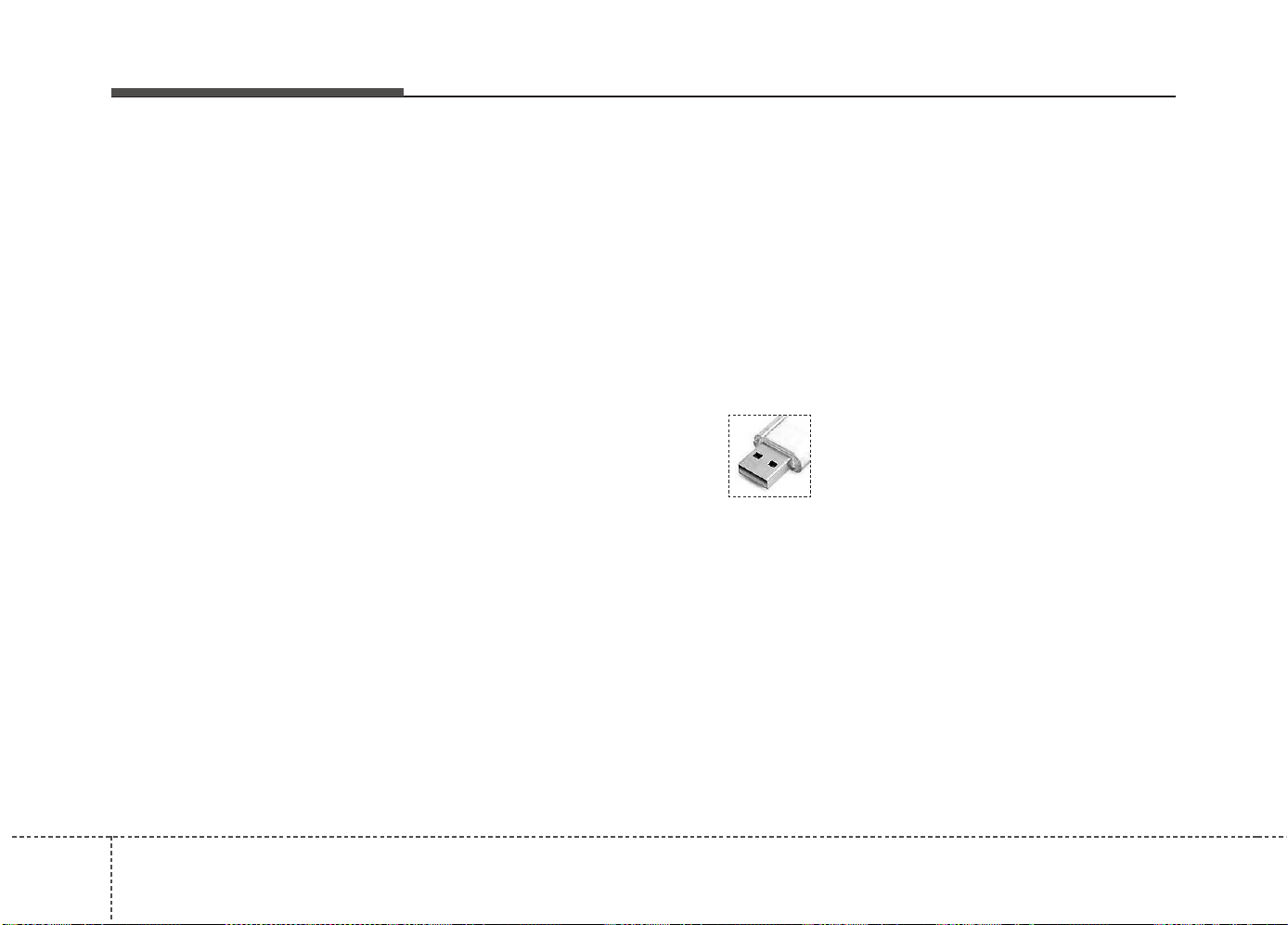
Features of your vehicle
1944
(Continued)
• If you use devices such as a USB
hub purchased separately, the
vehicle’s audio system may not
recognize the USB device. In that
case, connect the USB device
directly to the multimedia termi-
nal of the vehicle.
• If the USB device is divided by log-
ical drives, only the music files on
the highest-priority drive are rec-
ognized by car audio.
• Devices such as MP3 Player/
Cellular phone/Digital camera can
be unrecognizable by standard
USB I/F can be unrecognizable.
• Charging through the USB may
not be supported in some mobile
devices.
• USB HDD or USB types liable to
connection failures due to vehicle
vibrations are not supported. (i-
stick type)
• Some non-standard USB devices
(METAL COVER TYPE USB)
can be unrecognizable.
(Continued)
(Continued)
• Some USB flash memory readers
(such as CF, SD, micro SD, etc.) or
external-HDD type devices can be
unrecognizable.
• Music files protected by DRM
(DIGITAL RIGHTS MANAGE-
MENT) are not recognizable.
• The data in the USB memory may
be lost while using this audio.
Always back up important data on
a personal storage device.
• Please avoid using USB
memory products which
can be used as key
chains or cellular phone
accessories as they could
cause damage to the USB jack.
Please make certain only to use plug
type connector products.

Features of your vehicle
4 195
✽✽
NOTICE - USING THE iPod
®
DEVICE
• Some iPod models may not sup-
port communication protocol and
files may not properly play.
Supported iPod models:
- iPhone 3GS/4
- iPod touch 1st~4th generation
- iPod nano 1st~6th generation
- iPod classic
• The order of search or playback of
songs in the iPod can be different
from the order searched in the
audio system.
• If the iPod disabled due to its own
malfunction, reset the iPod.
(Reset: Refer to iPod manual)
• An iPod may not operate normal-
ly on low battery.
(Continued)
(Continued)
• Some iPod devices, such as the
iPhone, can be connected through
the Bluetooth
®
Wireless Technology
interface. The device must have
audio Bluetooth
®
Wireless
Technology capability (such as for
stereo headphone Bluetooth
®
Wireless Technology ). The device
can play, but it will not be con-
trolled by the audio system.
• To use iPod features within the audio,
use the cable provided upon purchas-
ing an iPod device.
• Skipping or improper operation may
occur depending on the characteris-
tics of your iPod/Phone device.
• If your iPhone is connected to both
the Bluetooth
®
Wireless Technology
and USB, the sound may not be prop-
erly played. In your iPhone, select the
Dock connector or Bluetooth
®
Wireless Technology to change the
sound output (source).
(Continued)
(Continued)
• When connecting iPod with the
iPod Power Cable, insert the con-
nector to the multimedia socket
completely. If not inserted com-
pletely, communications between
iPod and audio may be interrupted.
• When adjusting the sound effects
of the iPod and the audio system,
the sound effects of both devices
will overlap and might reduce or
distort the quality of the sound.
• Deactivate (turn off) the equalizer
function of an iPod when adjust-
ing the audio system’s volume, and
turn off the equalizer of the audio
system when using the equalizer of
an iPod.
• When not using iPod with car
audio, detach the iPod cable from
iPod. Otherwise, iPod may remain
in accessory mode, and may not
work properly.
• Beside support 1M cable when
purchasing iPod/iPhone products,
Long Cable cannot be recognized.

Features of your vehicle
1964
✽✽
NOTICE - USING THE
Bluetooth
®
Wireless
Technology
CELLULAR PHONE
• Do not use a cellular phone or per-
form Bluetooth
®
Wireless Technology
settings (e.g. pairing a phone)
while driving.
• Some Bluetooth
®
Wireless Technology
-enabled phones may not be recog-
nized by the system or fully com-
patible with the system.
• Before using Bluetooth
®
Wireless
Technology related features of the
audio system, refer your phone’s
User’s Manual for phone-side
Bluetooth
®
Wireless Technology
operations.
• The phone must be paired to the
audio system to use Bluetooth
®
Wireless Technology related fea-
tures.
• You will not be able to use the
hands-free feature when your
phone (in the car) is outside of the
cellular service area (e.g. in a tun-
nel, in a underground, in a moun-
tainous area, etc.).
(Continued)
(Continued)
• If the cellular phone signal is poor
or the vehicles interior noise is too
loud, it may be difficult to hear the
other person’s voice during a call.
• Do not place the phone near or
inside metallic objects, otherwise
communications with Bluetooth
®
Wireless Technology system or cel-
lular service stations can be dis-
turbed.
• While a phone is connected through
Bluetooth
®
Wireless Technology
your phone may discharge quicker
than usual for additional Bluetooth
®
Wireless Technology-related opera-
tions.
• Some cellular phones or other
devices may cause interference
noise or malfunction to audio sys-
tem. In this case, store the device
in a different location may resolve
the condition.
• Phone contact names should be
saved in English or they may not
be displayed correctly.
(Continued)
(Continued)
• If Priority is set upon vehicle igni-
tion(IGN/ACC ON), the Bluetooth
®
Wireless Technology phone will be
automatically connected.
Even if you are outside, the
Bluetooth
®
Wireless Technology
phone will be automatically con-
nected once you are in the vicinity
of the vehicle.
If you do not want automatic
Bluetooth
®
Wireless Technology
connection, turn the Bluetooth
®
Wireless Technology feature off.
• The hands-free call volume and
quality may differ depending on
the mobile phone type.
• Bluetooth
®
Wireless Technology
features can be used only when the
mobile phone has been paired and
connected with the device. For
more information on pairing and
connecting Bluetooth
®
Wireless
Technology enabled mobile phones,
refer to the “Phone Setup” section.
(Continued)

Features of your vehicle
4 197
(Continued)
• When a Bluetooth
®
Wireless
Technology mobile phone is con-
nected, a ( ) icon will appear at
the top of the screen. If a ( ) icon
is not displayed, this indicates that
a Bluetooth
®
Wireless Technology
enabled device has not been con-
nected. You must connect the
device before use. For more infor-
mation on Bluetooth
®
Wireless
Technology mobile phones, refer
to the “Phone Setup” section.
• Pairing and connecting a
Bluetooth
®
Wireless Technology
enabled mobile phone will work
only when the Bluetooth
®
Wireless
Technology option within your
mobile phone has been turned on.
(Methods of turning on the
Bluetooth
®
Wireless Technology
enabled feature may differ
depending on the mobile phone.)
(Continued)
(Continued)
• In some mobile phones, starting
the ignition while talking through
Bluetooth
®
Wireless Technology
enabled handsfree call will result
in the call becoming disconnected.
(Switch the call back to your
mobile phone when starting the
ignition.)
• Some features may not be support-
ed in some Bluetooth
®
Wireless
Technology mobile phone and
devices.
• Bluetooth
®
Wireless Technology
enabled operation may be unsta-
ble depending on the communica-
tion state.
• Placing the audio system within an
electromagnetic environment may
result in noise interference.

Features of your vehicle
1984
✽✽
NOTICE - USING VOICE
COMMAND
• The voice recognition feature of
this product supports recognition
of the commands listed within this
user’s manual.
• While using voice recognition,
operating the steering remote con-
trol or the device will terminate
voice recognition and allow you to
manually operate desired func-
tions.
• Position the microphone above the
head of the driver’s seat. For supe-
rior performance, maintain good
posture when saying voice com-
mands.
(Continued)
(Continued)
• Voice recognition may not func-
tion properly due to outside noise.
The following conditions can
affect the performance of Voice
Recognition:
-When the windows and sunroof
are open
-When the heating/cooling system
is on
-When passing a tunnel
-When driving on rugged and
uneven roads
• After downloading Bluetooth
®
Wireless Technology phone book,
the system requires some times to
convert the phone book into voice
information. During this time,
voice recognition may not operate
properly.
• Upon inputting your phone book,
special symbols and numbers can-
not be recognized by voice. For
example, “# John Doe%&” will be
recognized as “John Doe”.
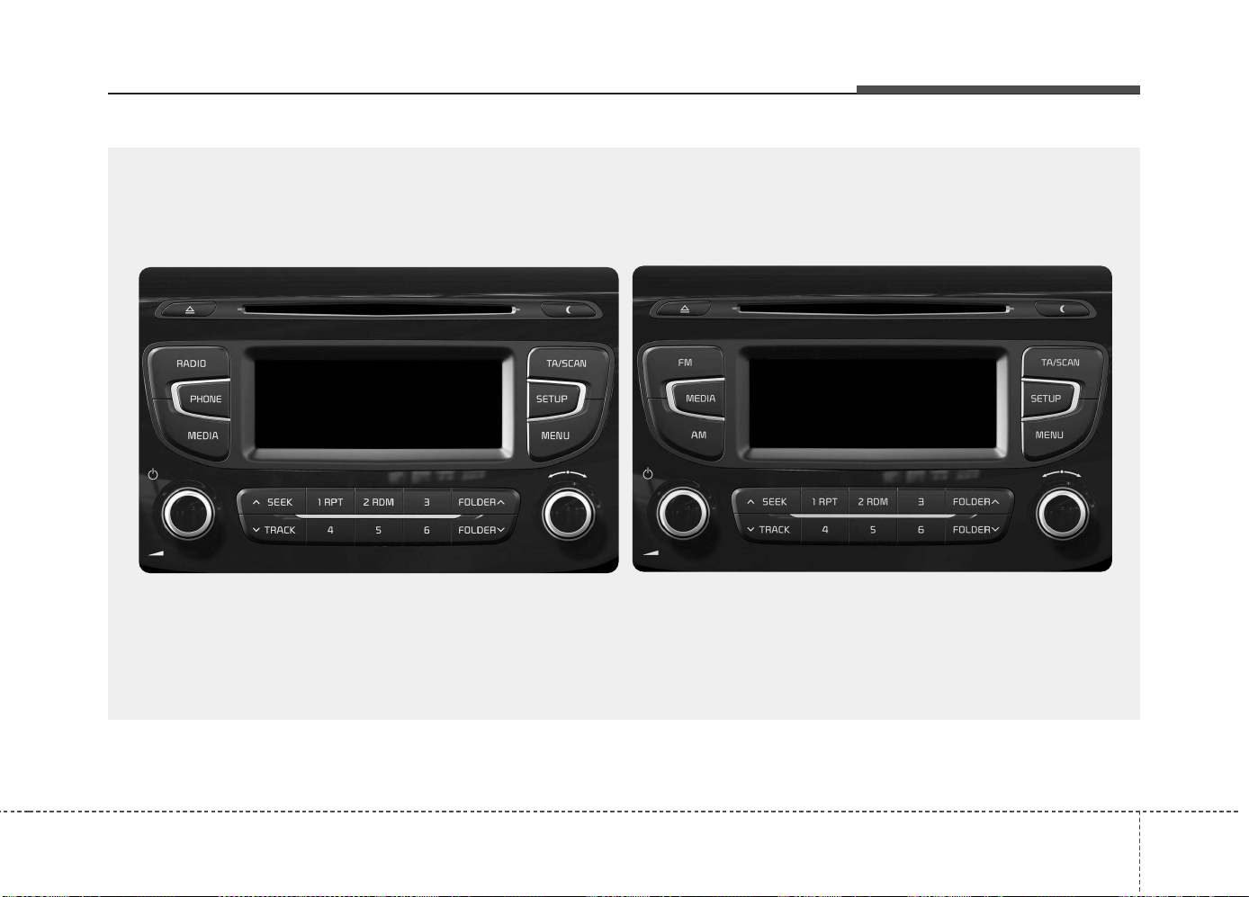
Features of your vehicle
4 199
■■
CD Player
■ Type A-1
■ Type A-2
(equipped with
Bluetooth
®
Wireless Technology)
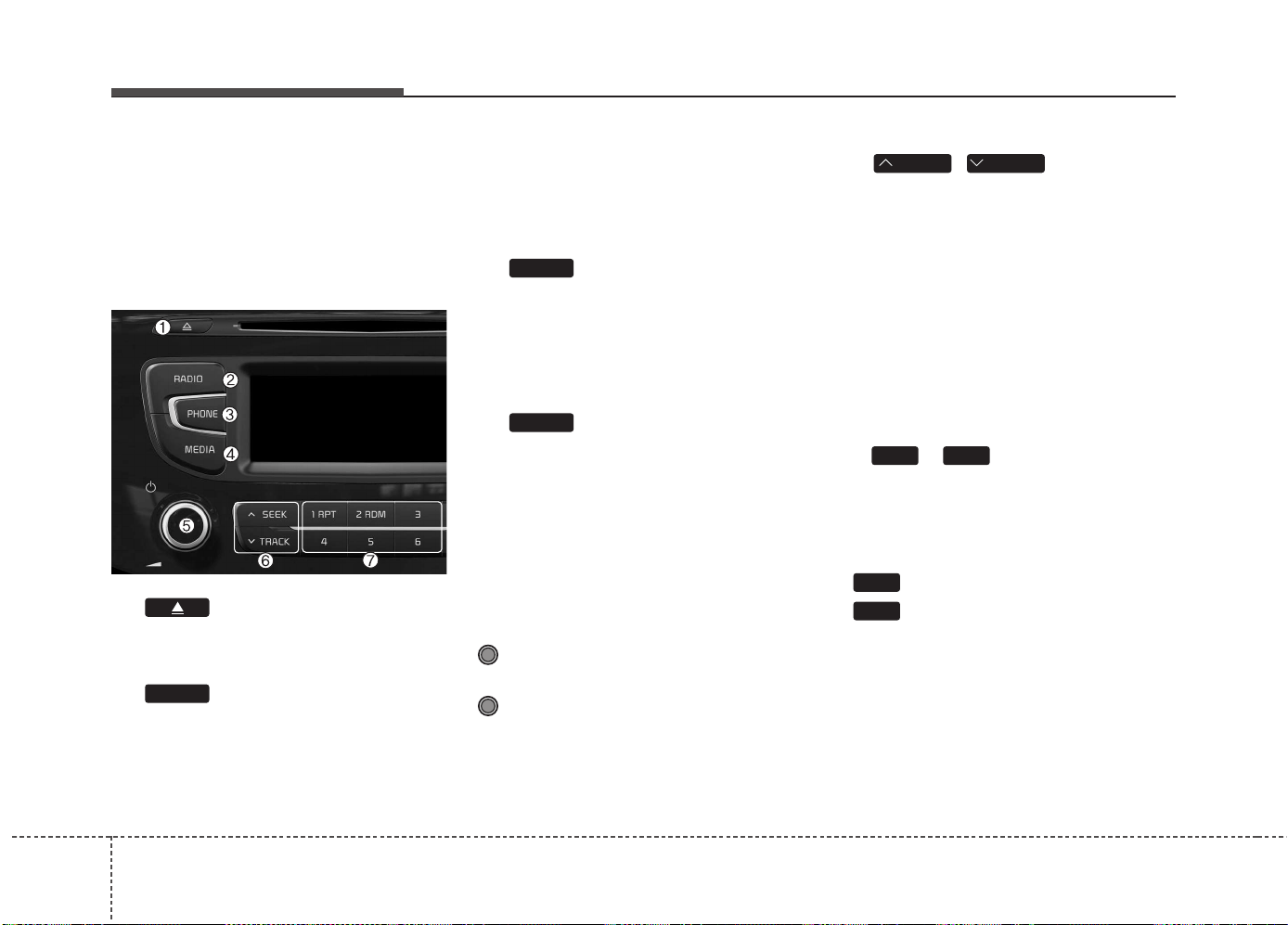
Features of your vehicle
2004
SYSTEM CONTROLLERS
AND FUNCTIONS
❈ Display and settings may differ
depending on the selected audio.
Audio Head Unit
(1) (EJECT)
Ejects the disc.
(2)
Changes to FM/AM mode.
Each time the key is pressed,the
mode is changed in order of FM1 ➟
FM2 ➟ FMA ➟ AM ➟ AMA.
(for DAB model)
FM1 ➟ FM2 ➟ FMA ➟ DAB1 ➟
DAB2 ➟ AM.
(3)
Operates Phone Screen
❈ When a phone is not connected,
the connection screen is dis-
played.
(4)
Changes to CD, USB(iPod
®
), AUX,
My Music, BT Audio mode.
Each time the key is pressed, the
mode is changed in order of CD,
USB(iPod
®
), AUX, My Music, BT
Audio.
(5) POWER/VOL kob
Power Knob: Turns power On/Off
by pressing the knob
Volume Knob: Sets volume by
turning the knob left/right
(6)
,
• Radio Mode : Automatically
searches for broadcast frequen-
cies.
• CD, USB, iPod®, My Music modes
- Shortly press the key (under 0.8
seconds): Moves to next or previ-
ous song (file)
- Press and hold the key (over 0.8
seconds): Rewinds or fast-forwards
the current song.
(7) ~ (Preset)
• Radio Mode: Saves frequencies
(channels) or receives saved fre-
quencies (channels)
• CD, USB, iPod®, My Music mode
- : Repeat
- : Random
In the Radio, Media, Setup, and
Menu pop up screen, the number
menu is selected.
2
RDM
1
RPT
61
TRACKSEEK
MEDIA
PHONE
RADIO
■ Type A-1
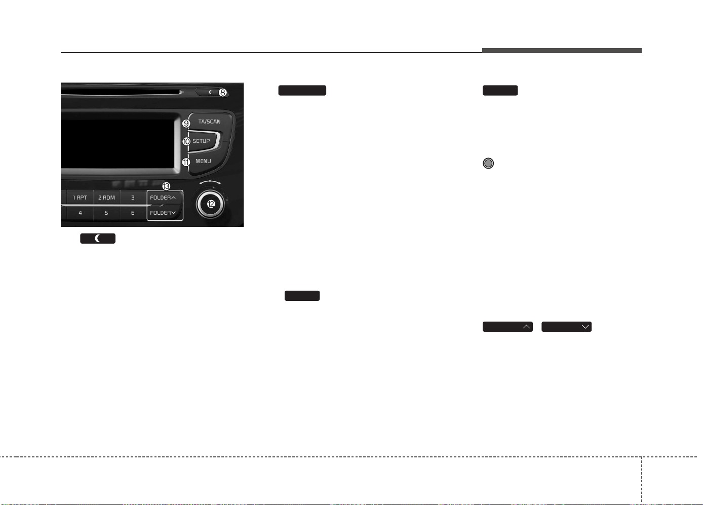
Features of your vehicle
4 201
(8)
• Each time the button is shortly
pressed (under 0.8 seconds), sets
Screen Off ➟ Screen On ➟ Screen
Off
❈ Audio operation is maintained and
only the screen will be turned Off.
In the Screen Off state, press any
key to turn the Screen On again.
(9)
• Radio Mode
- Shortly press the key (under 0.8
seconds): TA On/Off
- Press and hold the key (over 0.8
seconds): Previews each broad-
cast for 5 seconds each.
• Media mode
- Press and hold the key (over 0.8
seconds): Previews each song
(file) for 10 seconds each.
❈ Press and holding the key again to
continue listening to the current
song (file).
(10)
Moves to the Display, Sound, Phone,
System setting modes
(11)
Displays menus for the current m
ode.
❈ iPod
®
List : Move to parent category
(12) TUNE knob
• Radio mode : Changes frequency
by turning the knob left/right
• CD, USB, iPod®, My Music mode:
Searches .songs (files) by turning
the knob left/right.
❈ When the desired song is dis-
played, press the knob to play the
song.
Moves focus in all selection menus
and selects menus
(13) ,
MP3 CD / USB mode : Folder Search
FOLDERFOLDER
MEMU
SETUP
TA/SCAN
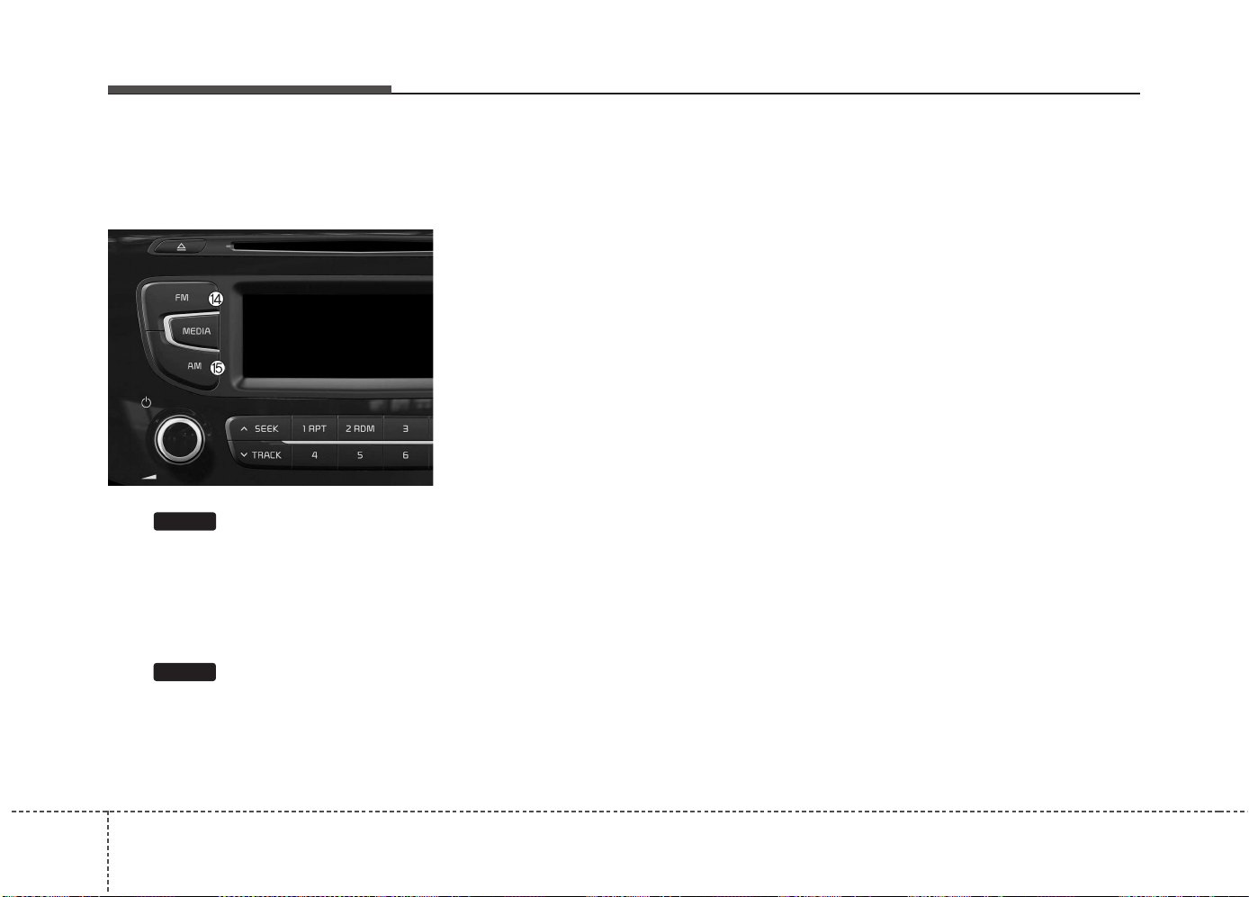
Features of your vehicle
2024
Audio Head Unit
(for Type A-2)
(14)
• Changes to FM mode.
• Each time the key is pressed, the
mode changed in order of FM1 ➟
➟ FM2 ➟ FMA.
(15)
• Changes to AM ➟ AMA mode.
AM
FM
■ Type A-2
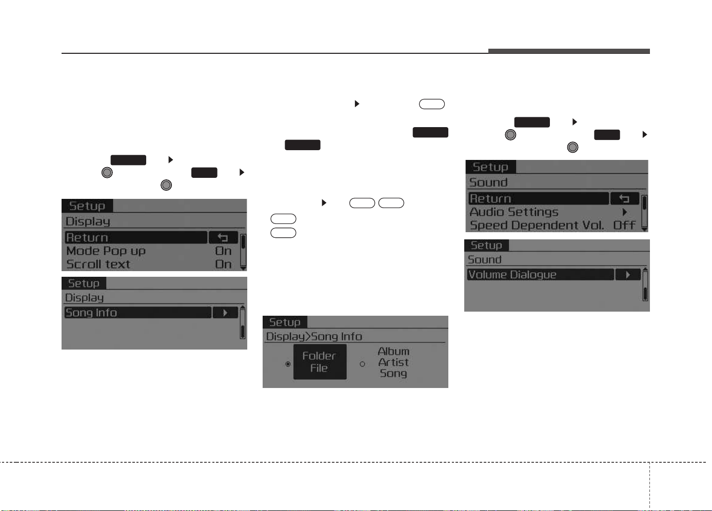
Features of your vehicle
4 203
SETUP
Display Settings
Press the key Select [Display]
through TUNE knob or key
Select menu through TUNE knob
Mode Pop up
[Mode Pop up] Changes .
selection mode
• During On state, press the
or key to display the mode
change pop up screen.
Scroll text
[Scroll text] Set /
• : Maintains scroll
• : Scrolls only one (1) time.
Song Info
When playing an MP3 file, select the
desired display info from ‘Folder/File’
or ‘Album/Artist/Song’.
Sound Settings
Press the key Select [Sound]
through TUNE knob or key
Select menu through TUNE knob
2
RDM
SETUP
OFF
ON
OFF
ON
MEDIA
RADIO
ON
1
RPT
SETUP
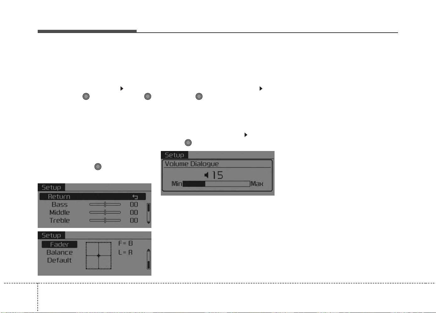
Features of your vehicle
2044
Audio Settings
This menu allows you to set the
‘Bass, Middle, Treble’ and the Sound
Fader and Balance.
Select [Audio Settings] Select
menu through TUNE knob Turn
TUNE knob left/right to set
• Bass, Middle, Treble : Selects the
sound tone.
• Fader, Balance : Moves the sound
fader and balance.
• Default : Restores default settings.
❈ Return : While adjusting values,
re-pressing the TUNE knob will
restore the parent menu.
Speed Dependent Volume Control
This feature is used to automatically
control the volume level according to
the speed of the vehicle.
Select [Speed Dependent Vol.] Set
[Off/On] of TUNE knob
Volume Dialogue
Adjusts voice recognition volume.
Select [Volume Dialogue] Set vol-
ume of TUNE knob
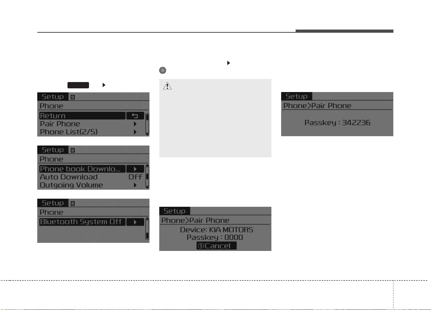
Features of your vehicle
4 205
Phone Settings
(
Bluetooth
®
Wireless
Technology equipped model)
Press the key Select [Phone]
Pair Phone
Select [Pair Phone] Set through
TUNE knob
➀ Search for device names as dis-
played on your mobile phone and
connect.
[Non SSP supported device]
(SSP: Secure Simple Pairing)
➁ After a few moments, a screen is
displayed where the passkey is
entered.
Enter the passkey “0000” to pair
your
Bluetooth
®
Wireless
Technology device with the car
audio system.
[SSP supported device]
➁ After a few moments, a screen is
displayed 6 digits passkey.
Check the passkey on your
Bluetooth
®
Wireless Technology
device and confirm.
❈ The device name and passkey will
be displayed on the screen for up
to 3 minutes. If pairing is not com-
pleted within the 3 minutes, the
mobile phone pairing process will
automatically be canceled.
➂ Pairing completion is displayed.
❈ In some mobile phones, pairing
will automatically be followed by
connection.
❈ It is possible to pair up to five
Bluetooth
®
Wireless Technology
enabled mobile phones.
SETUP
CAUTION
To pair a Bluetooth
®
Wireless
Technology enabled mobile
phone, authentication and con-
nection processes are first
required. As a result, you can-
not pair your mobile phone
while driving the vehicle. First
park your vehicle before use.
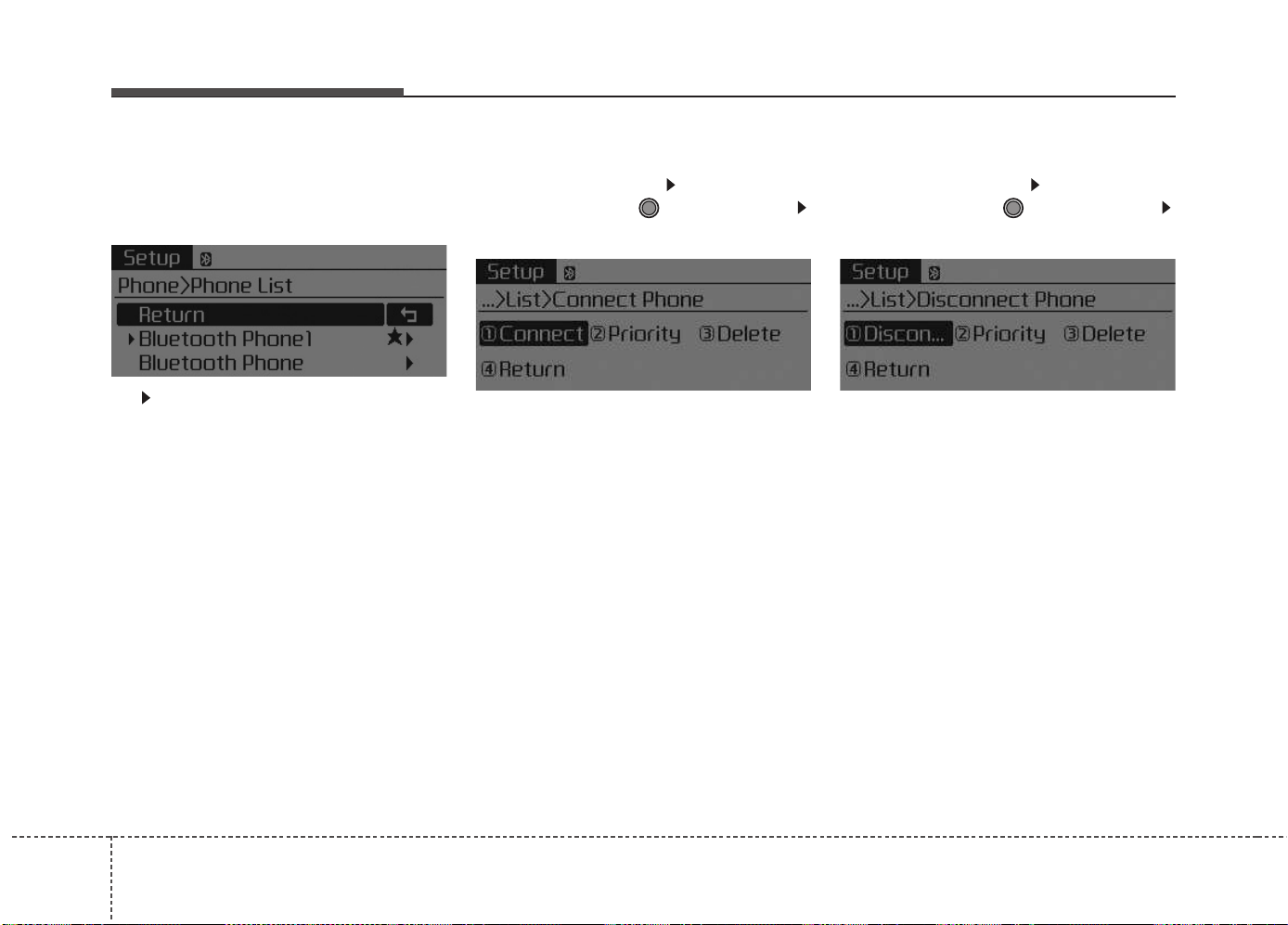
Features of your vehicle
2064
Phone List
The names of up to 5 paired phones
will be displayed.
A [ ] is displayed in front of the cur-
rently connected phone.
Select the desired name to setup the
selected phone.
• Connecting a phone
Select [Phone List] Select mobile
phone through TUNE knob
Select [Connect Phone]
➀ Select a mobile phone that is not
currently connected.
➁ Connect the selected mobile
phone.
➂ Connection completion is dis-
played.
❈ If a phone is already connected,
disconnect the currently connect-
ed phone and select a new phone
to connect.
• Disconnecting a connected phone
Select [Phone List] Select mobile
phone through TUNE knob
Select [Disconnect Phone]
➀ Select the currently connected
mobile phone.
➁ Disconnect the selected mobile
phone.
➂ Disconnection completion is dis-
played.
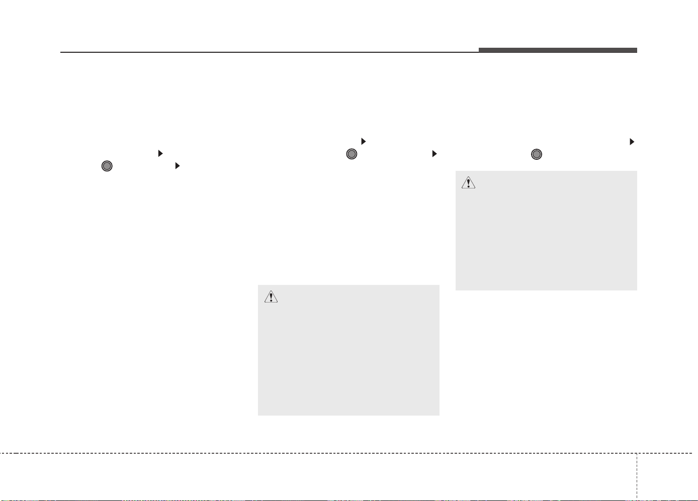
Features of your vehicle
4 207
• Changing connection sequence
(Priority)
This is used to change the order (pri-
ority) of automatic connection for the
paired mobile phones.
Select [Phone List] Select [Priority]
through TUNE knob Select No. 1
Priority mobile phone
➀ Select [Priority].
➁ From the paired phones, select
the phone desired for No.1 priority.
➂ The changed priority sequence is
displayed.
❈ Once the connection sequence
(priority) is changed, the new no. 1
priority mobile phone will be con-
nected.
- When the no. 1 priority cannot be
connected: Automatically attempts
to connect the most recently con-
nected phone.
- Cases when the most recently con-
nected phone cannot be connect-
ed: Attempts to connect in the order
in which paired phones are listed.
- The connected phone will automat-
ically be changed to No. 1 priority.
• Delete
Select [Phone List] Select mobile
phone through TUNE knob
Select [Delete]
➀ Select the desired mobile phone.
➁ Delete the selected mobile phone.
➂ Deletion completion is displayed.
❈ When attempting to delete a cur-
rently connected phone, the
phone is first disconnected.
Phone book Download
This feature is used to download
phone book and call histories into
the audio system.
Select [Phone book Download]
Select through TUNE knob
CAUTION
• The download feature may not
be supported in some mobile
phones.
• When downloading new phone
book, delete all previously
saved phone book before start-
ing download.
CAUTION
• When you delete a mobile
phone, the mobile phone
phone book will also be erased.
• For stable Bluetooth
®
Wireless
Technology communication,
delete the mobile phone from
the audio and also delete the
audio from your mobile phone.
Features of your vehicle
2084
Auto Download
When connecting a mobile phone, it
is possible to automatically download
new phone book and Call Histories.
Select [Auto Download] Set /
through TUNE knob
Outgoing Volume
This is used to set the volume of your
voice as heard by the other party
while on a
Bluetooth
®
Wireless
Technology enabled handsfree call.
Select [Outgoing Volume] Set vol-
ume through TUNE knob
❈ Even while on a call, the volume
can be changed by using the
,
key.
Bluetooth
®
Wireless Technology
System Off
This feature is used when you do not
wish to use the
Bluetooth
®
Wireless
Technology system.
Select [Bluetooth System Off] Set
through TUNE knob
❈ If a phone is already connected,
disconnect the currently connect-
ed phone and turn the
Bluetooth
®
Wireless Technology system off.
TRACKSEEK
OFF
ON
Features of your vehicle
4 209
Using the
Bluetooth
®
Wireless
Technology System
To use
Bluetooth
®
Wireless Technology
when the system is currently off, follow
these next steps.
• Turning On
Bluetooth
®
Wireless
Technology through the
Key
Press the key Screen
Guidance
❈ Moves to the screen where
Bluetooth
®
Wireless Technology
functions can be used and dis-
plays guidance.
• Turning On
Bluetooth
®
Wireless
Technology through the
Key
Press the key Select
[Phone] knob
➀ A screen asking whether to turn on
Bluetooth
®
Wireless Technology will
be displayed.
➁ On the screen, select to turn
on
Bluetooth
®
Wireless Technology
and display guidance.
❈ If the
Bluetooth
®
Wireless
Technology system is turned on,
the system will automatically try to
connect the most recently con-
nected
Bluetooth
®
Wireless
Technology mobile phone.
YES
SETUP
SETUP
PHONE
PHONE
CAUTION
• Bluetooth
®
Wireless Technology
connection may become inter-
mittently disconnected in some
mobile phones. Follow these
next steps to try again.
1)Turn the Bluetooth
®
Wireless
Technology function within
the mobile phone ON/OFF and
try to connect again.
2)Turn the mobile phone power
ON/OFF and try to connect
again.
3)Completely remove the mobile
phone battery, reboot, and
then try to connect again.
4)Reboot the audio system and
try to connect again
5)Delete all paired devices in
your mobile phone and the
audio system and pair again
for use.
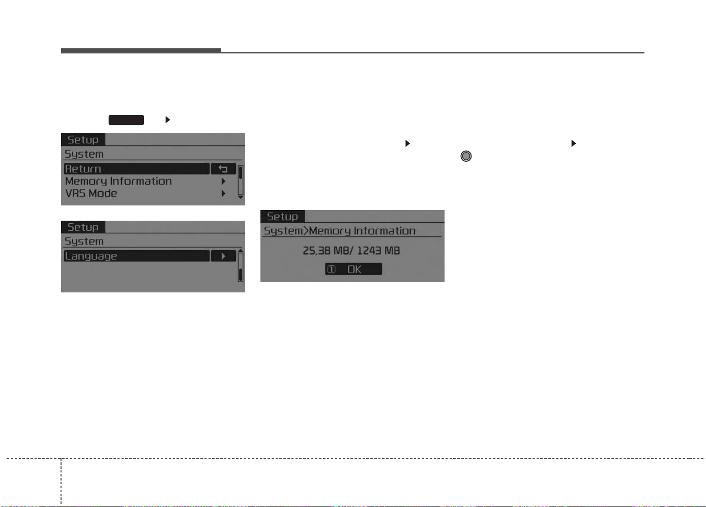
Features of your vehicle
2104
System Settings
Press the key Select [System]
Memory Information
(If equipped)
Displays currently used memory and
total system memory.
Select [Memory Information] OK
The currently used memory is dis-
played on the left side while the total
system memory is displayed on the
right side.
❈ May differ depending on the
selected audio.
VRS Mode (If equipped)
This feature is used to change voice
command feedback between Normal
and Expert modes.
Select [VRS Mode] Set through
TUNE knob
• Normal : This mode is for beginner
users and provides detailed
instructions during voice command
operation.
• Expert : This mode is for expert
users and omits some information
during voice command operation.
(When using Expert mode, guid-
ance instructions can be heard
through the [Help] or [Menu] com-
mands.
❈ May differ depending on the
selected audio.
SETUP
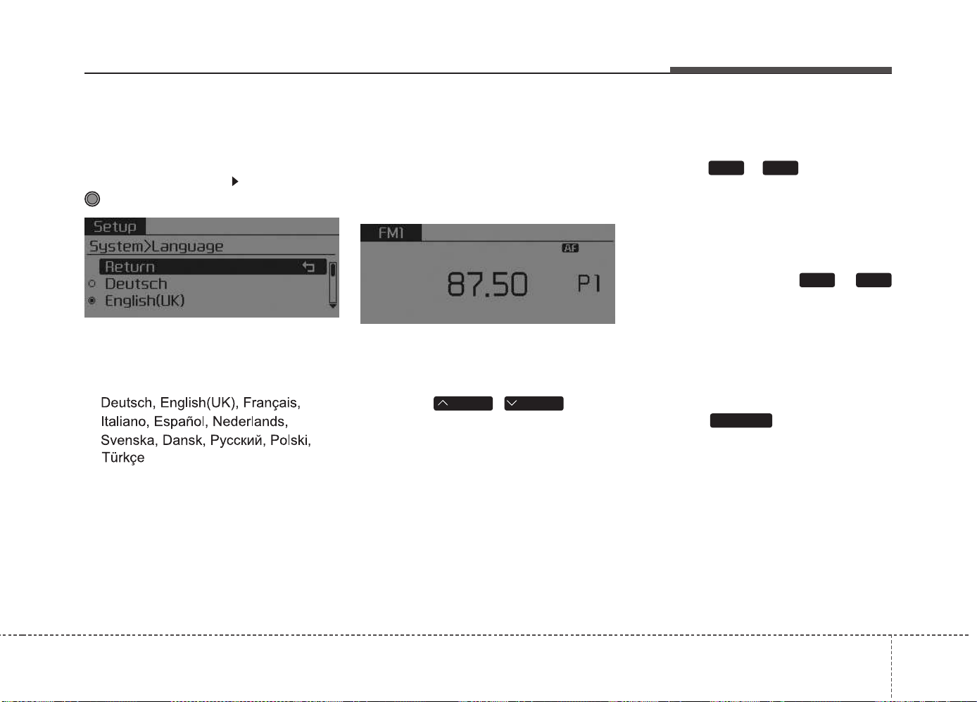
Features of your vehicle
4 211
Language
This menu is used to set the display
and voice recognition language.
Select [Language] Set through
TUNE knob
❈ The system will reboot after the
language is changed.
❈ Language support by region
RADIO
❈ RADIO may differ depending on
the selected audio.
Changing RADIO mode
SEEK
Press the
,
key
• Shortly pressing the key (under 0.8
seconds): Changes the frequency.
• Pressing and holding the key (over
0.8 seconds): Automatically search-
es for the next frequency.
Preset SEEK
Press the ~ key
• Shortly pressing the key (under 0.8
seconds): Plays the frequency
saved in the corresponding key.
• Pressing and holding the key (over
0.8 seconds): Pressing and holding
the desired key from ~
will save the currently playing
broadcast to the selected key and
sound a BEEP.
SCAN
Press the key
• Pressing and holding the key (over
0.8 seconds): The broadcast fre-
quency increases and previews
each broadcast for 5 seconds each.
After scanning all frequencies,
returns and plays the current
broadcast frequency.
TA/SCAN
61
61
TRACKSEEK
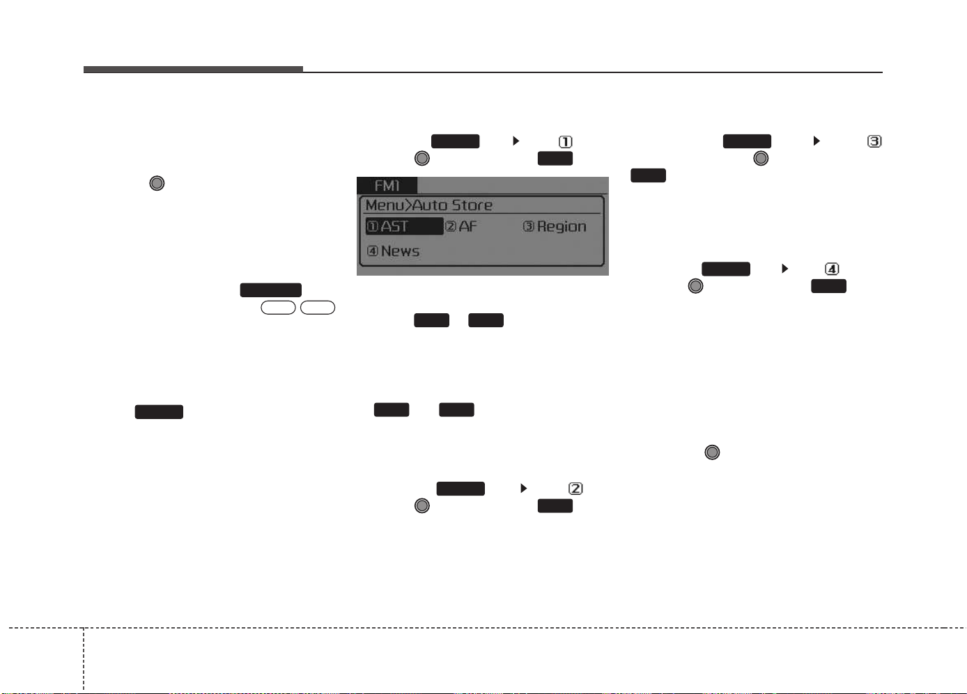
Features of your vehicle
2124
Selecting through manual
search
Turn the TUNE knob left/right to
adjust the frequency.
Traffic Announcement (TA)
Shortly pressing the key
(under 0.8 seconds): Set /
TA Traffic Announcement) mode.
MENU
Within key are the A.Store
(Auto Store) and Info functions.
AST (Auto Store)
Press the key Set [ AST]
through TUNE knob or key.
Select AST (Auto Store) to save fre-
quencies with superior reception to
presets ~ . If no frequen-
cies are received, then the most
recently received frequency will be
broadcast.
❈ Saves only to the Preset memory
~ of FMA or AMA
mode.
AF (Alternative Frequency)
Press the key Set [ AF]
through TUNE knob or key.
The Alternative Frequency option
can be turned On/Off.
Region
Press the key Set [
Region] through TUNE knob or
key.
The Region option can be turned
On/Off.
News
Press the key Set [ News]
through TUNE knob or key.
The News option can be turned
On/Off.
Info Volume
Info Volume refers to the sound vol-
ume upon receiving News or Traffic
information.
The info volume can be controlled by
turning the VOL knob left/right while
a news or traffic broadcast is playing.
❈ AF, Region, and News are RDS
Radio menus.
4
MENU
3
MENU
2
RDM
MENU
61
61
1
RPT
MENU
MENU
OFFON
TA/SCAN
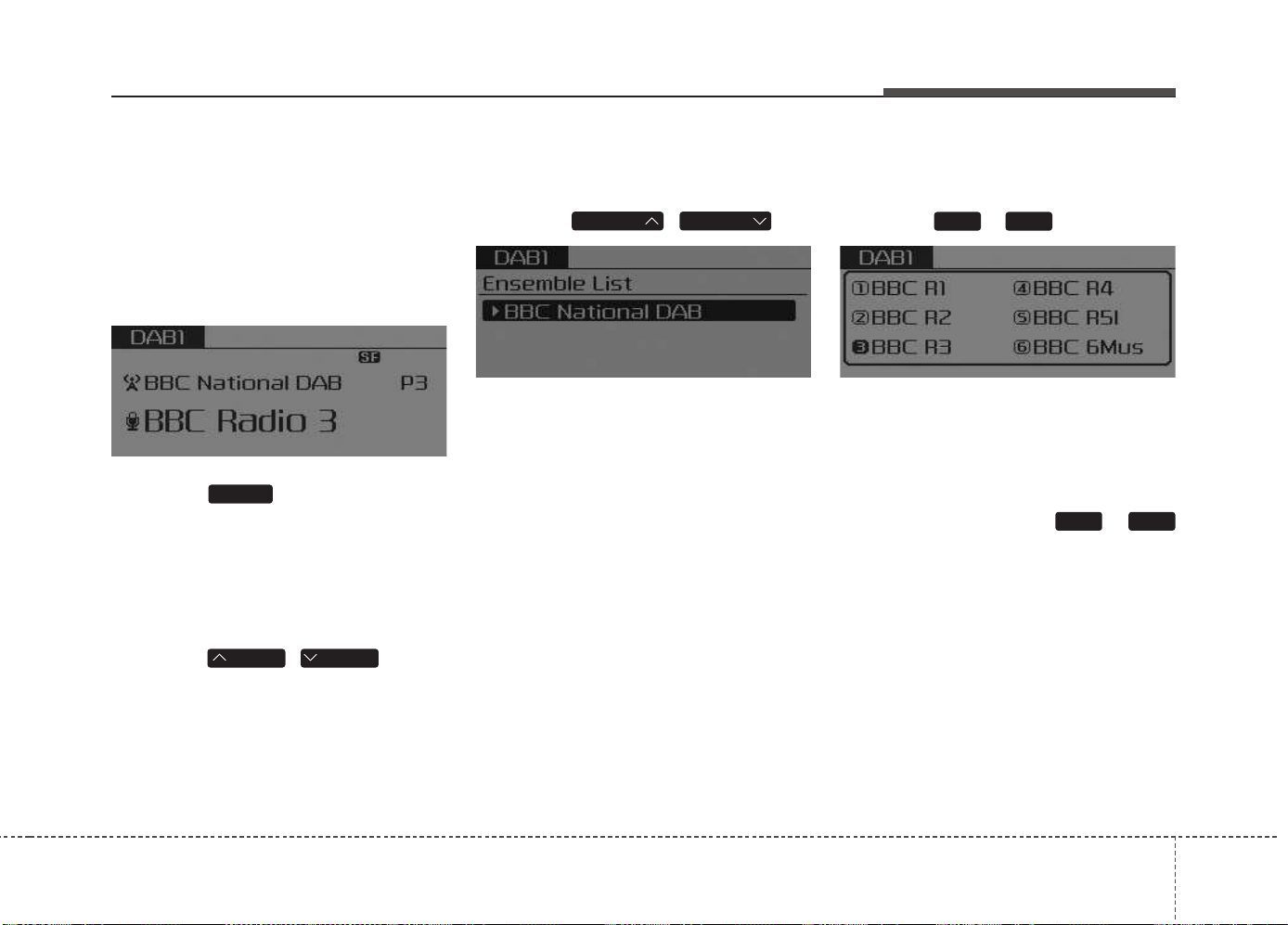
Features of your vehicle
4 213
DAB RADIO
(For DAB model)
❈ RADIO may differ depending on
the selected audio.
Changing RADIO mode
Press the key to change the
mode in order of FM1 ➟ FM2 ➟ FMA
➟ DAB1 ➟ DAB2 ➟ AM.
SEEK
Press the
,
key
• Shortly pressing the key (under 0.8
seconds): Changes the station.
• Press and hold the key (over 0.8
seconds): Change the Ensemble.
Ensemble
Press the , key
• Search the Ensemble. Use the
Tune knob to select the desired
Ensemble and select stations with-
in the Ensemble.
Preset SEEK
Press the ~ key
• Shortly pressing the key (under 0.8
seconds): Plays the station saved
in the corresponding key.
• Pressing and holding the key (over
0.8 seconds): Pressing and holding
the desired key from ~
will save the currently playing station
to the selected key and sound a
BEEP.
61
61
FOLDERFOLDER
TRACKSEEK
RADIO
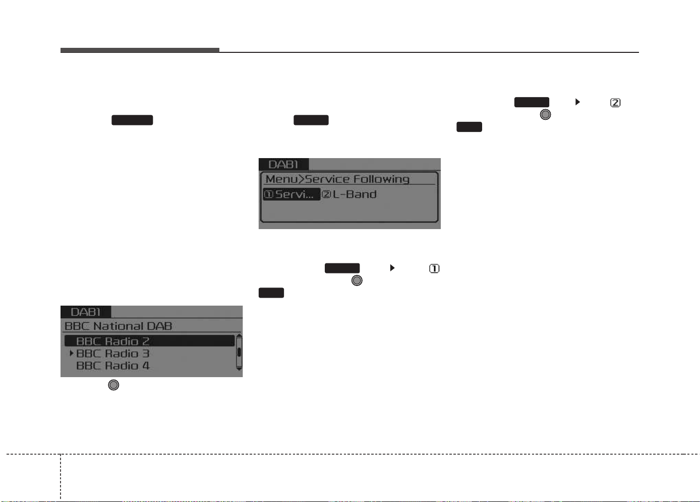
Features of your vehicle
2144
SCAN
Press the key
• Shortly pressing the key (under 0.8
seconds): TA On/Off
• Pressing and holding the key(over
0.8 seconds): The broadcast sta-
tion increases and previews each
broadcasts for 5 seconds each.
After scanning all stations, returns
and plays the current broadcast
station.
Selecting through manual
search
Turn the TUNE knob left/right to
select the station.
MENU
Within key are the Service.F
(Service Following) And L-Band
functions.
Service Following
Press the key Set [
Service.F] through TUNE knob or
key.
When the DAB signal is weak, the
Service Following feature will auto-
matically convert to the identical FM
broadcast when such a broadcast is
available.
L-Band
Press the key Set [ L-
Band] through TUNE knob or
key.
DAB Broadcasts include BAND III
and L-BAND according to the
Range. BAND III is always set as the
default while the L-BAND feature can
be turned on to search for L-BAND
broadcasts when in regions where L-
BAND broadcasts are available.
2
RDM
MENU
1
RPT
MENU
MENUTA/SCAN
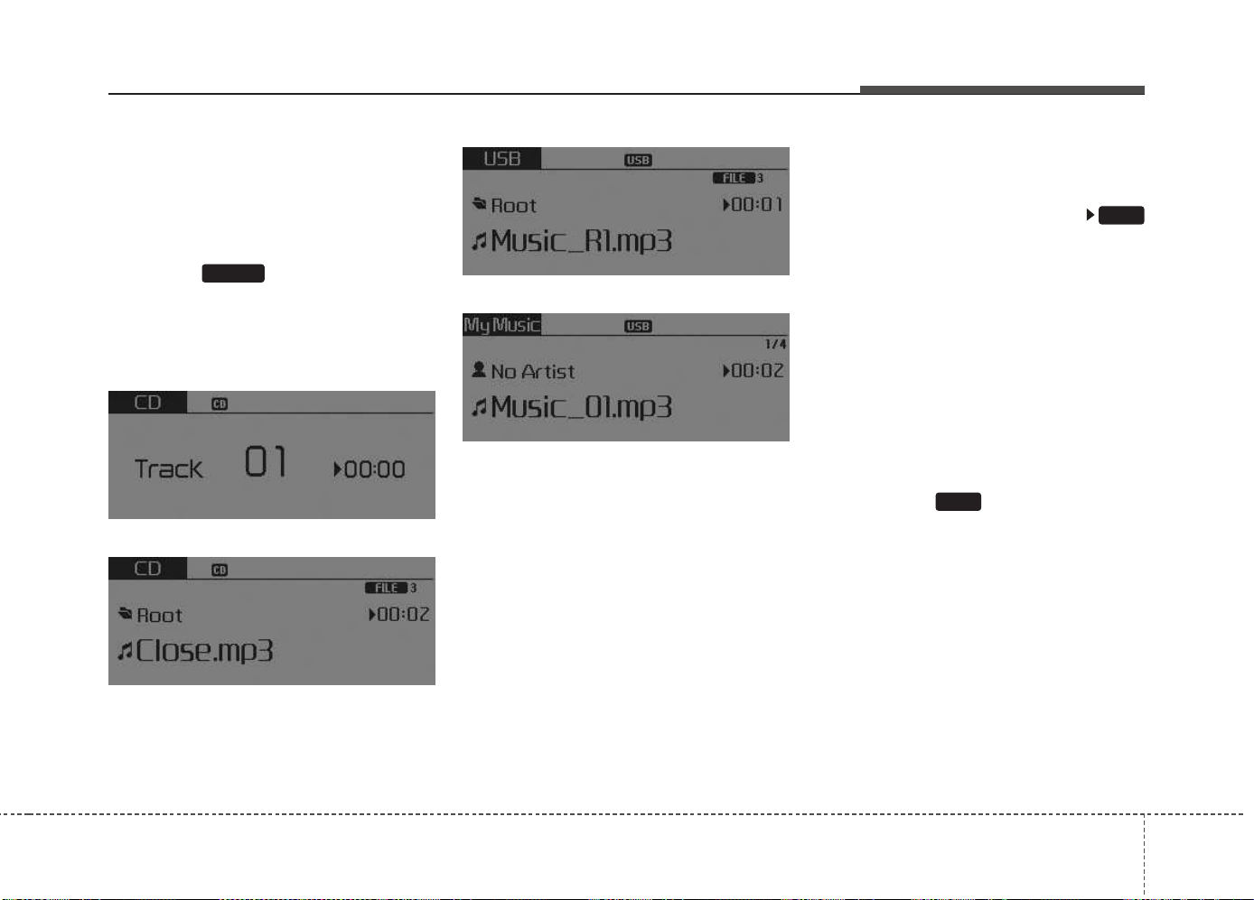
Features of your vehicle
4 215
BASIC METHOD OF USE :
Audio CD / MP3 CD / USB /
iPod
®
/ My Music
Press the key to change the
mode in order of CD ➟ USB(iPod
®
) ➟
AUX ➟ My Music ➟ BT Audio.
The folder/file name is displayed on
the screen.
<Audio CD>
<MP3 CD>
<USB>
<My Music>
❈ The CD is automatically played
when a CD is inserted.
❈ The USB music is automatically
played when a USB is connected.
Repeat
While song (file) is playing
(RPT) key
Audio CD, MP3 CD, USB, iPod
®
, My
Music mode: RPT on screen
• To repeat one song (Shortly press-
ing the key (under 0.8 seconds)):
Repeats the current song.
MP3 CD, USB mode: FLD.RPT on
screen
• To repeat folder (pressing twice):
repeats all files within the current
folder.
❈ Press the key again to turn
off repeat.
1
RPT
1
RPT
MEDIA
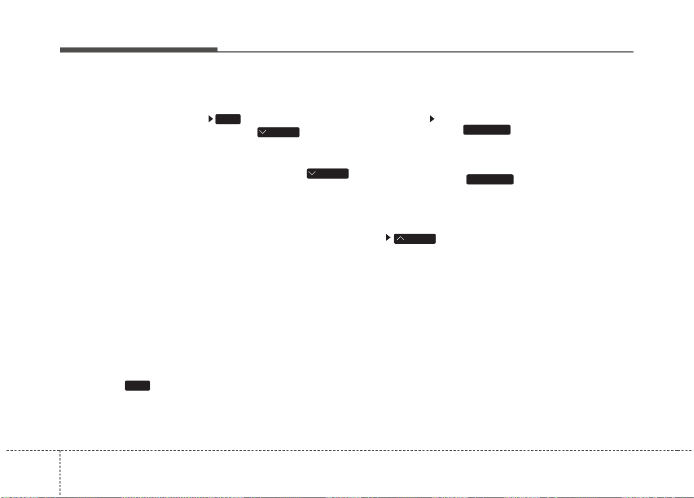
Features of your vehicle
2164
Random
While song (file) is playing
(RDM) key
Audio CD, My Music mode: RDM on
screen
• Random (Shortly pressing the
key): Plays all songs in random
order.
MP3 CD, USB mode: FLD.RDM on
screen
• Folder Random (Shortly pressing
the key): Plays all files within the
current folder in random order.
MP3 CD, USB mode: RDM on
screen
• Random (pressing twice): Plays all
files in random order.
iPod
®
mode: RDM on screen
• Random (Shortly pressing the
key): Plays all files in random
order.
❈ Press the key again to turn
off random.
Changing Song/File
While song (file) is playing
key
• Shortly pressing the key: Plays the
current song from the beginning.
❈ If the key is pressed
again within 1 second, the previ-
ous song is played.
• Pressing and holding the key (over
0.8 seconds): Rewinds the song.
While song (file) is playing
key
• Shortly pressing the key : Plays the
next song.
• Pressing and holding the key (over
0.8 seconds): Fast forwards the
song.
Scan
• Pressing and holding the
key (over 0.8 seconds) :
Scans all songs for 10 seconds
starting from the next song.
❈ Pressing and holding the
key again to turn off.
TA/SCAN
TA/SCAN
SEEK
TRACK
TRACK
2
RDM
2
RDM
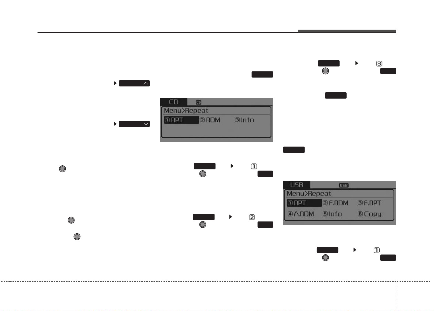
Features of your vehicle
4 217
Folder Search : MP3 CD, USB
Mode
While file is playing
,(Folder Up) key
• Searches the next folder.
While file is playing
(Folder Down) key
• Searches the parent folder.
❈ If a folder is selected by pressing
the TUNE knob, the first file
within the selected folder will be
played.
Searching Songs (File)
• Turning TUNE knob : Searches
for songs (files)
• Pressing TUNE knob : Plays
selected song (file).
MENU : Audio CD
Press the Audio CD mode
key to set the Repeat, Random,
Information features.
Repeat
Press the key Set [ RPT]
through the TUNE knob or
key to repeat the current song.
❈ Press RPT again to turn off.
Random
Press the key Set [ RDM]
through the TUNE knob or
key to randomly play songs within
the CD
❈ Press RDM again to turn off.
Information
Press the key Set [ Info]
through the TUNE knob or
key to display information of the cur-
rent song.
❈ Press the key to turn off
info display.
MENU : MP3 CD / USB
Press the MP3 CD / USB mode
key to set the Repeat, Folder
Random, Folder Repeat, All
Random, Information, and Copy fea-
tures.
Repeat
Press the key Set [ RPT]
through the TUNE knob or
key to repeat the current song.
❈ Press RPT again to turn off.
1
RPT
MENU
MENU
MENU
3
MENU
2
RDM
MENU
1
RPT
MENU
MENU
FOLDER
FOLDER
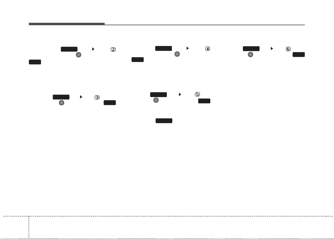
Features of your vehicle
2184
Folder Random
Press the key Set [
F.RDM] through the TUNE knob or
key to randomly play songs
within the current folder.
❈ Press F.RDM again to turn off.
Folder Repeat
Press the key Set [ F.RPT]
through the TUNE knob or
key to repeat songs within the cur-
rent folder.
❈ Press F.RPT again to turn off.
All Random
Press the key Set [
A.RDM] through the TUNE knob
or key to randomly play all
songs within the CD / USB.
❈ Press A.RDM again to turn off.
Information
Press the key Set [ Info]
through the TUNE knob or
key to display information of the cur-
rent song.
❈ Press the key to turn off
info display.
Copy (If equipped)
Press the key Set [ Copy]
through the TUNE knob or
key.
This is used to copy the current song
into My Music. You can play the
copied Music in My Music mode.
❈ If another key is pressed while
copying is in progress, a pop up
asking you whether to cancel
copying is displayed.
❈ If another media is connected or
inserted (USB, CD, iPod
®
, AUX)
while copying is in progress, copy-
ing is canceled.
❈ Music will not be played while
copying is in progress.
6
MENU
MENU
5
MENU
4
MENU
3
MENU
2
RDM
MENU
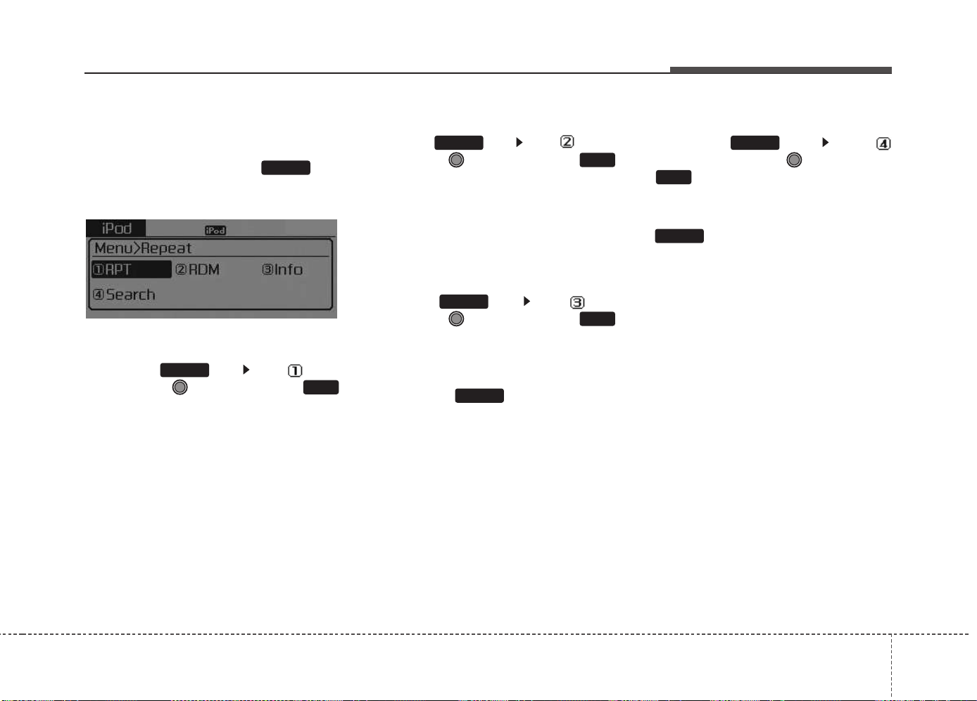
Features of your vehicle
4 219
MENU : iPod
®
In iPod
®
mode, press the key
to set the Repeat, Random,
Information and Search features.
Repeat
Press the key Set [ RPT]
through the TUNE knob or
key to repeat the current song.
❈ Press RPT again to turn repeat
off.
Random
Press the key Set [ RDM]
through the TUNE knob or
key.
Plays all songs within the currently
playing category in random order.
❈ Press RDM again to turn off.
Information
Press the key Set [ Info]
through the TUNE knob or
key.
Displays information of the current
song.
❈ Press the key to turn off
info display.
Search
Press the key Set [
Search] through the TUNE knob
or key.
Displays iPod
®
category list.
❈ Searching iPod
®
category is
key pressed, move to par-
ent category.
MENU
4
MENU
MENU
3
MENU
2
MENU
1
RPT
MENU
MENU
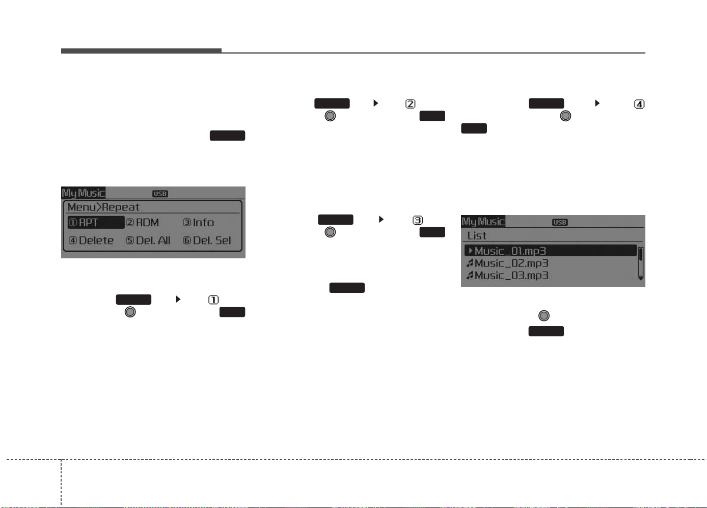
Features of your vehicle
2204
MENU : My Music Mode
(If equipped)
In My Music mode, press the
key to set the Repeat, Random,
Information, Delete, Delete All, and
Delete Selection features.
Repeat
Press the key Set [ RPT]
through the TUNE knob or
key.
Repeats the currently playing song.
❈ Press RPT again to turn repeat off.
Random
Press the key Set [ RDM]
through the TUNE knob or
key.
Plays all songs in random order.
❈ Press RDM again to turn random
off.
Information
Press the key Set [ Info]
through the TUNE knob or
key.
Displays information of the current
song.
❈ Press the key to turn off
info display.
Delete
Press the key Set [
Delete] through the TUNE knob or
key.
• Deletes currently playing file
In the play screen, pressing delete
will delete the currently playing
song.
• Deletes file from list
➀ Select the file you wish to delete
by using the TUNE knob.
➁ Press the key and select
the delete menu to delete the
selected file.
MENU
4
MENU
MENU
3
MENU
2
RDM
MENU
1
RPT
MENU
MENU
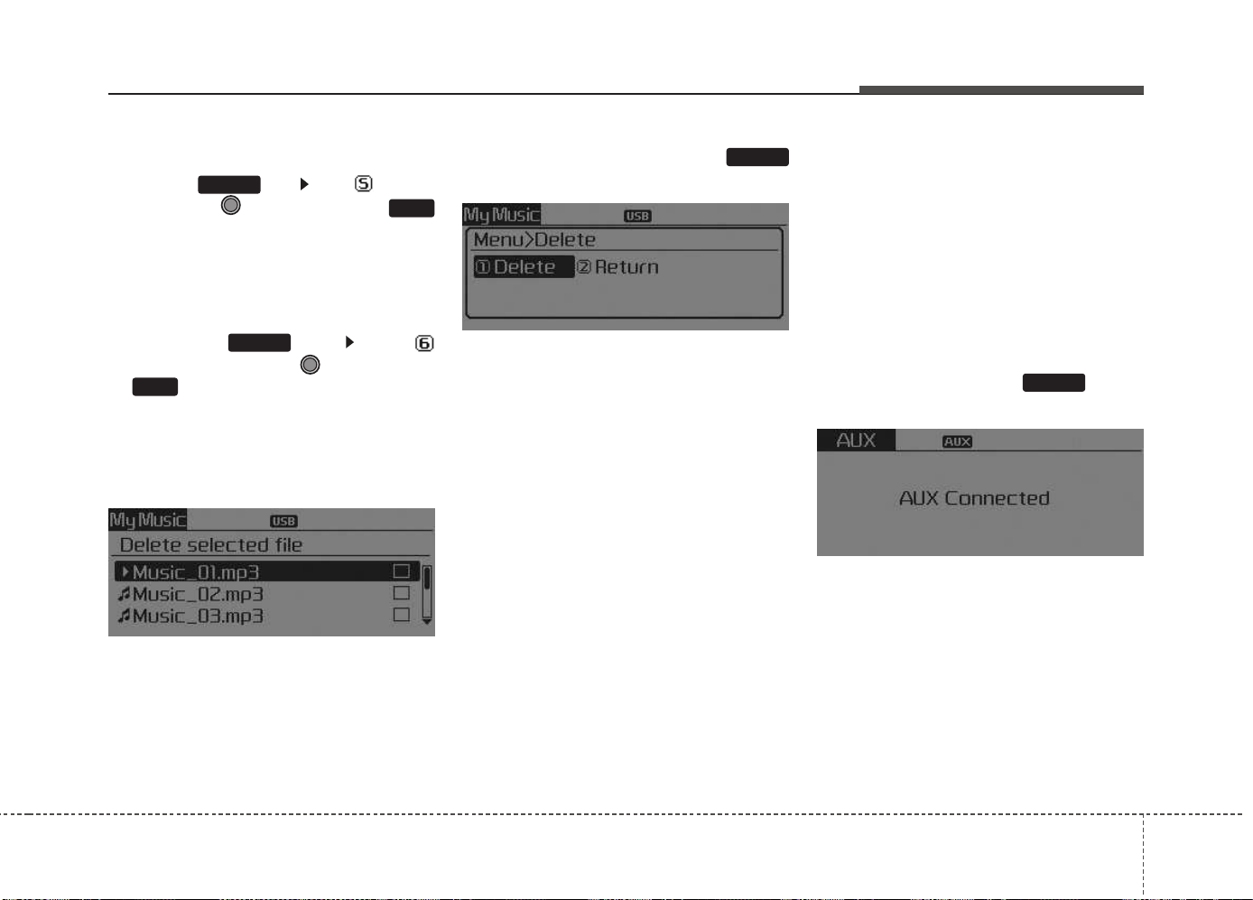
Features of your vehicle
4 221
Delete All
Press the key Set [ Del.All]
through the TUNE knob or
key.
Deletes all songs of My Music.
Delete Selection
Press the key Set [
Del.Sel] through the TUNE knob
or key.
Songs within My Music are selected
and deleted.
➀ Select the songs you wish to
delete from the list.
➁ After selecting, press the
key and select the delete menu.
✽✽
NOTICE - USING THE My
Music
• Even if memory is available, a
maximum of 6,000 songs can be
stored.
• The same song can be copied up to
1,000 times.
• Memory info can be checked in
the System menu of Setup.
AUX
AUX is used to play external MEDIA
currently connected with the AUX
terminal.
AUX mode will automatically start
when an external device is connect-
ed with the AUX terminal.
If an external device is connected,
you can also press the key to
change to AUX mode.
❈ AUX mode cannot be started
unless there is an external device
connected to the AUX terminal.
✽✽
NOTICE - USING THE AUX
Fully insert the AUX cable into the
AUX terminal for use.
MEDIA
MENU
6
MENU
5
MENU
Features of your vehicle
2224
Bluetooth
®
Wireless
Technology AUDIO
Type A-1
What is
Bluetooth
®
Wireless
Technology?
Bluetooth
®
Wireless Technology
allows devices to be connected in a
short distance, including hands-free
devices, stereo headsets, wireless
remote controllers, etc. For more
information, visit the
Bluetooth
®
Wireless Technology website at
www.Bluetooth.com
Before using
Bluetooth
®
Wireless
Technology audio features
•
Bluetooth
®
Wireless Technology
audio may not be supported
depending on the compatibility of
your
Bluetooth
®
Wireless Technology
mobile phone.
• In order to use
Bluetooth
®
Wireless Technology audio, you
must first pair and connect the
Bluetooth
®
Wireless Technology
mobile phone.
• The Bluetooth
®
word mark and
logos are registered trademarks
owned by Bluetooth
®
SIG, Inc. and
any use of such marks by Kia is
under license. Other trademarks
and trade names are those of their
respective owners. A Bluetooth
®
enabled cell phone is required to
use
Bluetooth
®
Wireless Technology.
•
Bluetooth
®
Wireless Technology
audio can be used only when the
[Audio Streaming] of Phone is
turned On.
WARNING
Driving while distracted can
result in a loss of vehicle con-
trol that may lead to an acci-
dent, severe personal injury,
and death. The driver’s primary
responsibility is in the safe and
legal operation of a vehicle, and
use of any handheld devices,
other equipment, or vehicle sys-
tems which take the driver’s
eyes, attention and focus away
from the safe operation of a
vehicle or which are not permis-
sible by law should never be
used during operation of the
vehicle.
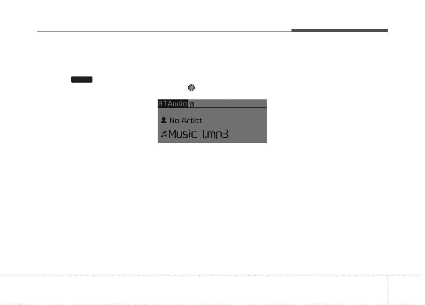
Features of your vehicle
4 223
Starting
Bluetooth
®
Wireless
Technology Audio
• Press the key to change the
mode in order of CD ➟ USB ➟ AUX
➟ My Music ➟ BT Audio.
• If BT Audio is selected,
Bluetooth
®
Wireless Technology audio will start
playing.
❈ Audio may not automatically start
playing in some mobile phones.
Using the
Bluetooth
®
Wireless
Technology audio features
• Play / Pause
Press the TUNE knob to play and
pause the current song.
❈ The previous song / next song /
play / pause functions may not be
supported in some mobile
phones.
MEDIA
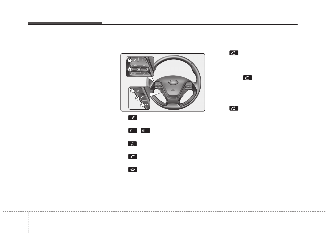
Features of your vehicle
2244
PHONE (If equipped)
Before using the
Bluetooth
®
Wireless
Technology
phone features
• In order to use
Bluetooth
®
Wireless
Technology phone, you must first
pair and connect the
Bluetooth
®
Wireless Technology mobile
phone.
• If the mobile phone is not paired or
connected, it is not possible to
enter Phone mode. Once a phone
is paired or connected, the guid-
ance screen will be displayed.
• If Priority is set upon vehicle igni-
tion (IGN/ACC ON), the
Bluetooth
®
Wireless Technology phone will be
automatically connected. Even if
you are outside, the
Bluetooth
®
Wireless Technology phone will be
automatically connected once you
are in the vicinity of the vehicle. If
you do not want automatic
Bluetooth
®
Wireless Technology
phone connection, set the
Bluetooth
®
Wireless Technology
power to OFF.
Making a call using the
Steering-wheel mount controls
(1) key : Mutes the microphone
during a call.
(2) , key : Raises or lowers
speaker volume.
(3) key : Activates voice recogni-
tion.
(4) (If equipped) key : Places
and transfers calls.
(5) (If equipped) key : Ends calls
or cancels functions.
• Check call history and making call
- Shortly press (under 0.8 seconds)
the key on the steering
remote controller.
- The call history list will be dis-
played on the screen.
- Press the key again to con-
nect a call to the selected number.
• Redialing the most recently called
number
- Press and hold (over 0.8 seconds)
the key on the steering
remote controller.
- The most recently called number is
redialed.
-
+
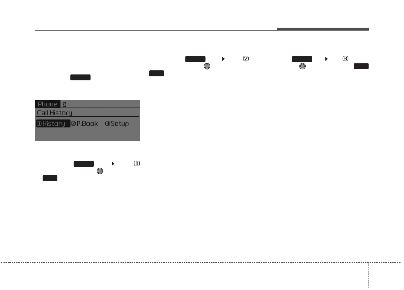
Features of your vehicle
4 225
Phone MENU
Type A-1
Press the key to display
three menus (Call History, Phone
Book, Phone Setup).
History
Press the key Set [
History] through the TUNE knob
or key.
The call history is displayed and can
be used to select a number and
make a call.
If call history does not exist, a screen
asking whether to download call his-
tory is displayed. (The download fea-
ture may not be supported in some
mobile phones)
P.Book
Press the key Set [ P.
Book] through the TUNE knob or
key.
The phone book is displayed and
can be used to select a number and
make a call.
❈ If more than one number is saved
to one contact, then a screen
showing the mobile phone num-
ber, Home and office number is
displayed. Select the desired num-
ber to make the call.
❈ If phone book do not exist, a
screen asking whether to down-
load phone book is displayed.
(The download feature may not be
supported in some mobile
phones)
Setup
Press the key Set [ Setup]
through the TUNE knob or
key.
The
Bluetooth
®
Wireless Technology
mobile phone setup screen is dis-
played. For more information, refer to
“Phone Setup”.
3
PHONE
2
RDM
PHONE
1
RPT
PHONE
PHONE
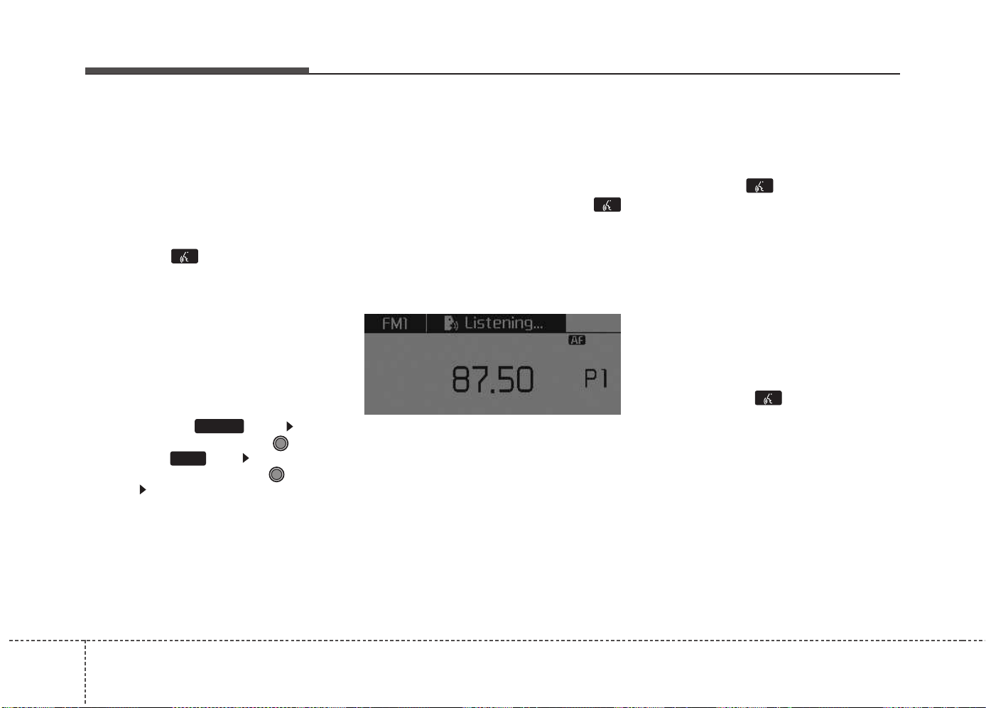
Features of your vehicle
2264
VOICE COMMAND
(If equipped)
Starting Voice Command
• To start voice command, shortly
press the key on the steering
wheel remote controller.
• If voice command is in [Normal
Mode], then the system will say
“Please say a command. Beep”
❈ If voice command is in [Expert
Mode], then the system will only
say a “Beep-”
❈ Setting Voice command [Normal
Mode]/[Expert Mode]:
Press the key Select
[System] through the TUNE
knob or key Select [VRS
Mode] through the TUNE
knob Set [Normal Mode]/[Expert
Mode]
• Say the voice command.
✽✽
NOTICE
For proper voice recognition, say the
voice command after the guidance
message and the “Beep” sound.
Skipping the Guidance
Message
While the guidance message is
being stated, shortly press the
key (under 0.8 seconds) to discontin-
ue the guidance message and sound
the “beep”.
After the “beep”, say the voice com-
mand.
Ending Voice Command
• While using voice command, press
and hold the key (over 0.8 sec-
onds) to end voice command.
• While using voice command,
pressing the steering wheel
remote controller or a different key
will end voice command.
• In a state where the system is wait-
ing for your voice command, say
“cancel” or “end” to end voice com-
mand.
• In a state where the system is wait-
ing for your voice command, short-
ly press the key (under 0.8
seconds) to end voice command.
4
PHONE
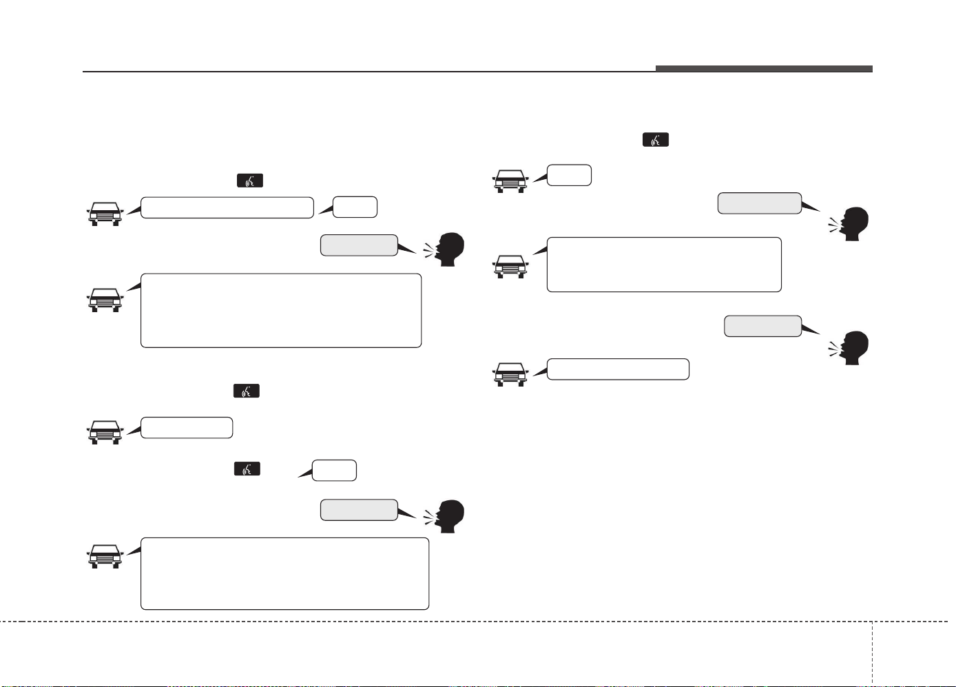
Features of your vehicle
4 227
Illustration on using voice commands
• Starting voice command.
Shortly pressing the key (under 0.8 seconds):
• Skipping Voice Recognition
Shortly pressing the key (under 0.8 seconds):
• End voice command.
Shortly pressing the key (under 0.8 seconds):
while guidance message is being
stated
More Help
Phone book
Cancel
More Help
Please say a command
Please say a...
More Help.
You can say Radio, FM, AM, Media, CD, USB, AUX,
My Music, iPod
®
, Bluetooth Audio, Phone, Call
History or Phone book. Please say a command.
Phone book
Please say the name of the Phone book
you want to call.
More Help.
You can say Radio, FM, AM, Media, CD, USB, AUX,
My Music, iPod
®
, Bluetooth Audio, Phone, Call
History or Phone book. Please say a command.
Beep-
Beep-
Beep-
Beep Beep.. (end beep)
Shortly pressing the key
(under 0.8 seconds):

Features of your vehicle
2284
Voice Command List
• Common Commands : These commands can be used in most operations. (However a few commands may not be
available during certain operations)
Command Function
More Help Provides guidance on commands that can be
used anywhere in the system.
Help Provides guidance on commands that can be
used within the current mode.
Call<Name> Calls <Name> saved in
phone book
Ex) Call “John Smith”
Phone Provides guidance on Phone related com-
mands. After saying this command, say “Call
History”, “
Phone book
”, “Dial Number” to exe-
cute corresponding functions.
Call History Displays the Call History screen.
Phone book
Displays the
phone book
screen. After saying
this command, say the name of a
phone book
saved in the
phone book
to automatically con-
nect the call.
Dial Number Displays the Dial number screen. After saying
this command, you can say the number that
you want to call.
Redial Connects the most recently called number.
Radio
•
When listening to the radio, displays the next
radio screen. (FM1➟FM2➟FMA➟AM➟AMA)
•
When listening to a different mode, displays
the most recently played radio screen.
Command Function
FM
•
When currently listening to the FM radio, main-
tains the current state.
•
When listening to a different mode, displays
the most recently played FM screen.
FM1(FM One) Displays the FM1 screen.
FM2(FM Two) Displays the FM2 screen.
FMA Displays the FMA screen.
AM Displays the AM screen.
AMA Displays the AMA screen.
FM Preset 1~6 Plays the most recently played broadcast
saved in FM Preset 1~6.
AM Preset 1~6 Plays the broadcast saved in AM Preset 1~6.
FM 87.5~107.9 Plays the FM broadcast of the corresponding
frequency.
❈ Range can be different by application frequen-
cy of corresponding country.
AM 530~1710 Plays the AM broadcast of the corresponding
frequency.
❈ Range can be different by application frequen-
cy of corresponding country.
TA on Enables Traffic Announcement
TA off Disables Traffic Announcement
News on Enables RDS News feature
News off Disables RDS News feature

Features of your vehicle
4 229
Command Function
Media Moves to the most recently played media
screen.
Play Track 1~30 If a music CD has been inserted, plays the
corresponding track.
CD Plays the music saved in the CD.
Search CD Moves to the CD track or file selection screen.
•
For audio CDs, move to the screen and say
the track number to play the corresponding
track.
•
Moves to MP3 CD file selection screen.
After manually operate the device to select
and play music.
USB Plays USB music.
Search USB Moves to USB file selection screen. After
manually operate the device to select and play
music.
iPod
®
Plays iPod
®
music.
Search iPod
®
Moves to the iPod
®
file selection screen. After,
manually operate the device to select and play
music.
My Music Plays the music saved in My Music.
Search My Music Moves to My Music file selection screen. After
manually operate the device to select and play
music.
Command Function
AUX (Auxiliary) Plays the connected external device.
Bluetooth
®
Audio Plays the music saved in connected
Bluetooth
®
Wireless Technology
device.
Mute Mutes the radio or music volume.
Pardon? Repeats the most recent comment.
Cancel (Exit) Ends voice command.

Features of your vehicle
2304
• FM/AM radio Commands : Commands available dur-
ing FM, AM radio operation.
• Audio CD Commands : Commands available during
Audio CD operation.
Command Function
Preset 1~6 Plays the broadcast saved in Preset 1~6.
Auto Store Automatically selects radio broadcast fre-
quencies with superior reception and saves in
Presets 1~6.
Preset Save 1~6 Saves the current broadcast frequency to
Preset 1~6.
Seek up Plays the next (higher) receivable broadcast.
Seek down Plays the previous (lower) receivable broadcast.
Next Preset Selects the preset number next to the most
recently selected preset. (Example: When cur-
rently listening to preset no. 3, then preset no.
4 will be selected.)
Previous Preset Selects the preset number previous to the
most recently selected preset. (Example:
When currently listening to preset no. 3, then
preset no. 2 will be selected.)
Scan Scans receivable frequencies from the current
broadcast and plays for 10 seconds each.
Preset Scan Moves to the next preset from the current
present and plays for 10 seconds each.
AF on Enables Alternative Frequency feature
AF off Disables Alternative Frequency feature
Region Enables Region feature
Region off Disables Region feature
Command Function
Random Randomly plays the tracks within the CD.
Random Off Cancels random play to play tracks in sequen-
tial order.
Repeat Repeats the current track.
Repeat Off Cancels repeat play to play tracks in sequen-
tial order.
Next Track Plays the next track.
Previous Track Plays the previous track.
Scan Scans the tracks from the next track for 10
seconds each.
Track 1~30 Plays the desired track number.
Information Displays the information screen of the current
track.

Features of your vehicle
4 231
• MP3 CD / USB Commands: Commands available
during USB and MP3 CD operation.
•iPod
®
Commands: Commands available during iPod
®
operation.
Command Function
Random Randomly plays the files within the current
folder.
All Random Randomly plays all saved files.
Random Off Cancels random play to play files in sequential
order.
Repeat Repeats the current file.
Folder Repeat Repeats all files in the current folder.
Repeat Off Cancels repeat play to play files in sequential
order.
Next File Plays the next file.
Previous File Plays the previous file.
Scan Scans the files from the next files for 10 sec-
onds each.
Information Displays the information screen of the current
file.
Copy Copies the current file into My Music.
Command Function
All Random Randomly plays all saved songs.
Random Randomly plays the songs within the current
category.
Random Off Cancels random play to play songs in sequen-
tial order.
Repeat Repeats the current song.
Repeat Off Cancels repeat play to play songs in sequen-
tial order.
Next Song Plays the next song.
Previous Song Plays the previous song.
Information Displays the information screen of the current
song.

Features of your vehicle
2324
• My Music Commands : Commands available during
My Music operation.
• Commands available during
Bluetooth
®
Wireless
Technology audio streaming from mobile phone oper-
ation Command Operation.
Command Function
Random Randomly plays all saved files.
Random Off Cancels random play to play files in sequential
order.
Repeat Repeats the current file.
Repeat Off Cancels repeat play to play files in sequential
order.
Next File Plays the next file.
Previous File Plays the previous file.
Scan Scans the files from the next files for 10 sec-
onds each.
Information Displays the information screen of the current
file.
Delete Deletes the current file. You will bypass an
additional confirmation process.
Delete All Deletes all files saved in My Music. You will
bypass an additional confirmation process.
Command Function
Play Plays the currently paused song.
Pause Pauses the current song.
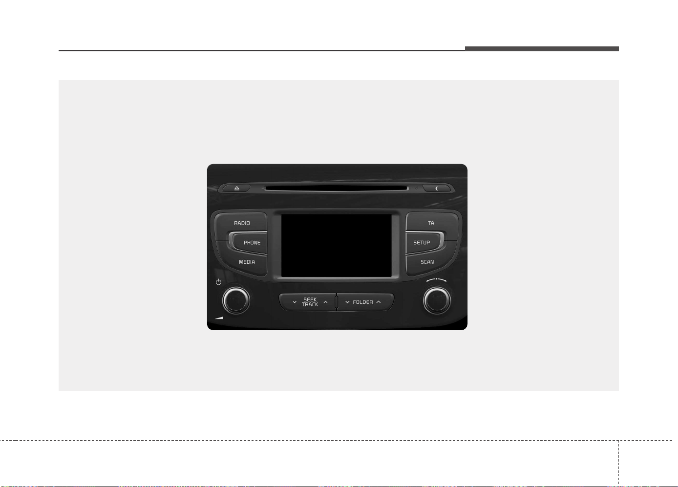
Features of your vehicle
4 233
■■
CD Player
(equipped with
Bluetooth
®
Wireless Technology)
■ Type B-1
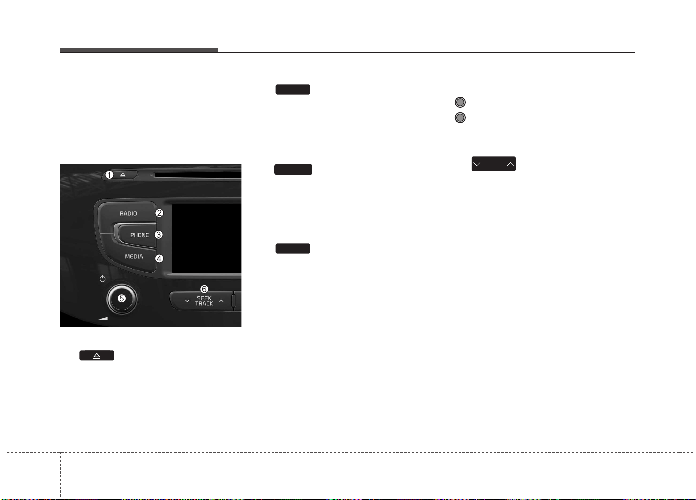
Features of your vehicle
2344
SYSTEM CONTROLLERS
AND FUNCTIONS
Audio Head Unit
(1) (EJECT)
Ejects the disc.
(2)
Converts to Radio(FM/AM) mode.
Each time the key is pressed, the
mode is changed in order of FM1 ➟
FM2 ➟ FMA ➟ AM ➟ AMA.
(3)
Converts to Phone mode
❈ When a phone is not connected,
the connection screen is dis-
played.
(4)
Start Media mode
Each time the key is pressed, the
mode is changed in order of CD,
USB(iPod
®
) AUX, My Music, BT
Audio.
(5) POWER/VOL knob
Power : Press to turn power on/off.
Volume : Turn left / right to control
volume.
(6)
When pressed shortly (under 0.8
seconds)
- Radio mode : plays previous / next
frequency.
- Media (CD / USB / iPod
®
/ My Music
/BT Audio) modes : changes the
track, Song(file)
When pressed and held (0.8 seconds)
- Radio mode : continuously changes
the frequency. Upon release, plays
the current frequency.
- Media(CD / USB / iPod
®
/ My
Music) modes : rewinds or fast for-
wards the track or file
- During a Handsfree call, controls
the call volume.
SEEK
TRACK
MEDIA
PHONE
RADIO
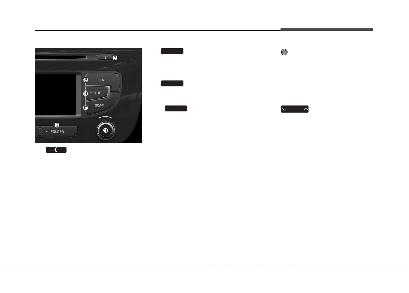
Features of your vehicle
4 235
(7)
• Each time the button is shortly
pressed (under 0.8 seconds), sets
Screen Off ➟ Screen On ➟ Screen
Off
❈ Audio operation is maintained and
only the screen will be turned Off.
In the Screen Off state, press any
key to turn the Screen On again.
(8)
Set TA(Traffic Announcement) feature
On/Off.
(9)
Converts to Setup mode.
(10)
• Radio Mode
- Press and hold the key (over 0.8
seconds): Previews each broad-
cast for 5 seconds each.
• Media mode
- Press and hold the key (over 0.8
seconds): Previews each song
(file) for 10 seconds each.
❈ Press and holding the key again to
continue listening to the current
song (file).
(11) TUNE knob
- Radio mode : turn to change
broadcast frequencies.
- Media (CD / USB / iPod
®
/ My
Music) modes : turn to search
tracks/channels/files.
(12)
MP3 CD / USB mode : Folder Search
❈ May differ depending on the
selected audio.
FOLDER
SCAN
SETUP
TA
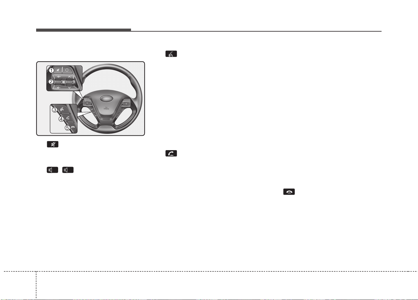
Features of your vehicle
2364
Steering-wheel mount controls
(1) : Mutes the microphone dur-
ing a call.
(2) , : Used to control volume.
(3) (If equipped)
When pressed shortly (under 0.8
seconds)
- Starts voice recognition
- When selecting during a voice
prompt, stops the prompt and con-
verts to voice command waiting
state
When pressed and held (over 0.8
seconds)
- Ends voice recognition
(4)
When pressed shortly (under 0.8 sec-
onds)
- When pressed in the phone screen,
displays call history screen
- When pressed in the dial screen,
makes a call
- When pressed in the incoming call
screen, answers the call
- When pressed during call waiting,
switches to waiting call (Call Waiting)
When pressed and held (over 0.8
seconds)
- When pressed in the
Bluetooth
®
Wireless Technology Handsfree
wait mode, redials the last call
- When pressed during a
Bluetooth
®
Wireless Technology Handsfree
call, switches call back to mobile
phone (Private)
- When pressed while calling on the
mobile phone, switches call back to
Bluetooth
®
Wireless Technology
Handsfree (Operates only when
Bluetooth
®
Wireless Technology
Handsfree is connected)
(5)
Ends phone call
-
+
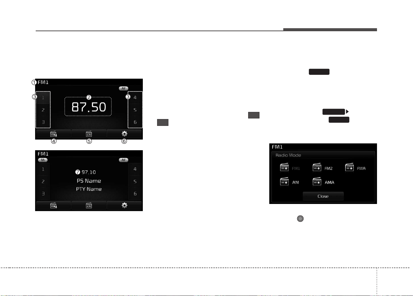
Features of your vehicle
4 237
RADIO MODE
Basic Mode Screen
(1) Mode Display
Displays currently operating mode.
(2) Frequency
Displays the current frequency.
(3) Preset
Displays current preset number
~.
(4) Preset Display
Displays saved presets.
(5) Auto Store
Automatically saves frequencies with
superior reception to Preset buttons.
(6) RDS Menu
Displays the RDS Menu.
(7) RDS Info
Displays RDS broadcast information.
Switching to Radio Mode
Pressing the key will change
the operating mode in order of FM1
➟ FM2 ➟ FMA ➟ AM ➟ AMA.
If [Pop-up Mode] / [Mode Pop-up] is
turned on within [Display],
then pressing the key will
display the Radio Pop-up Mode
screen.
Turn the TUNE knob to move the
focus. Press the knob to select.
RADIO
SETUP
RADIO
6
1
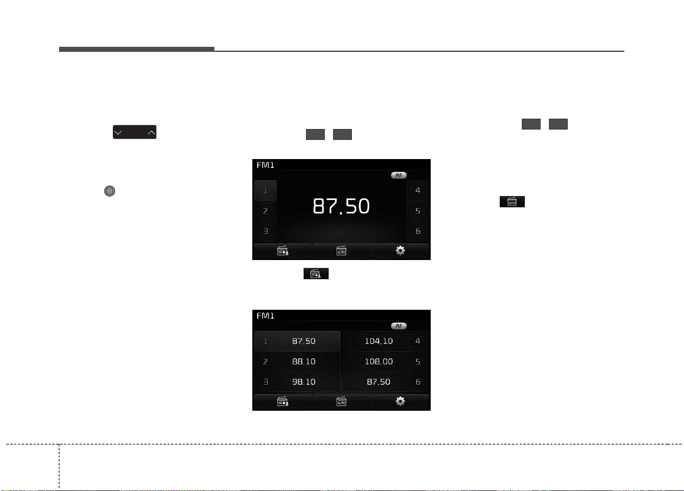
Features of your vehicle
2384
Searching Radio Frequencies
Using Seek
Press the key to play the
previous/next frequency.
Using TUNE
Turn the TUNE knob to select the
desired frequency.
Using Radio Mode
Selecting/Saving Presets
Press the ~ buttons to play
the desired preset.
Press the button to display the
broadcast information for the fre-
quency saved to each button.
✽✽
NOTICE
While listening to a frequency you
want to save as a preset, press and
hold one of the
~ preset but-
tons (over 0.8 seconds) to save the
current frequency to the selected
preset.
Auto Store
Press the button to automati-
cally save receivable frequencies to
Preset buttons.
✽✽
NOTICE
While Auto Store is operating, press-
ing the [Cancel] button again will
cancel Auto Store and restore the
previous frequency.
61
61
SEEK
TRACK
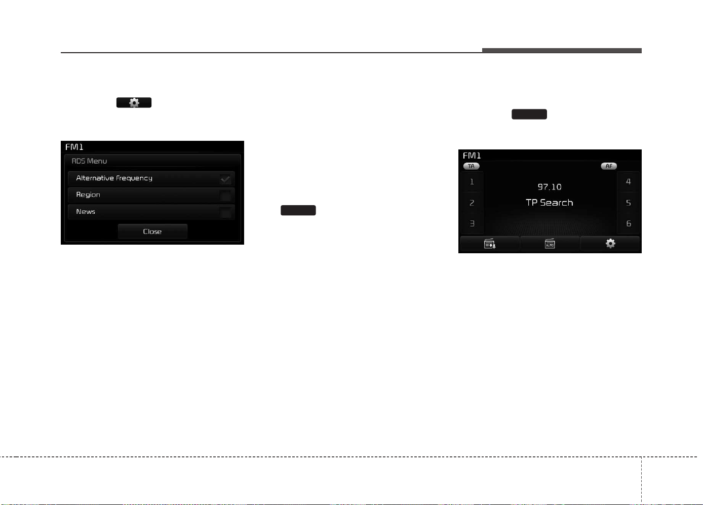
Features of your vehicle
4 239
RDS Menu
Press the button to set the
AF (Alternative Frequency), Region
and News features.
✽✽
NOTICE
The RDS Menu is not supported
within AM or AMA mode.
Scan
Press the key (over 0.8 seconds):
Previews each broadcast for 5 sec-
onds each.
✽✽
NOTICE
Once scan is complete, the previous
frequency will be restored.
While Scan is operating, pressing
the key (under 0.8 seconds)
will cancel the scan operation.
TA (Traffic Announcement)
Press the key to turn the TA
(Traffic Announcement) feature
On/Off.
TA
SCAN

Features of your vehicle
2404
MEDIA MODE
Switching to Media Mode
Pressing the key will change
the operating mode in order of CD ➟
USB (iPod
®
) ➟ AUX ➟ My Music ➟
BT Audio.
If [Pop-up Mode] / [Mode Pop-up] is
turned on within [Display],
then pressing the key will dis-
play the Media Pop-up Mode screen.
Turn the TUNE knob to move the
focus. Press the knob to select.
✽✽
NOTICE
The media mode pop up screen can
be displayed only when there are
two or more media modes turned
on.
Title Icon
When a
Bluetooth
®
Wireless
Technology, iPod
®
, USB, or AUX
device is connected or a CD is
inserted, the corresponding mode
icon will be displayed.
Icon Title
Bluetooth
®
WirelessTechnology
CD
iPod
®
USB
AUX
MEDIA
SETUP
MEDIA
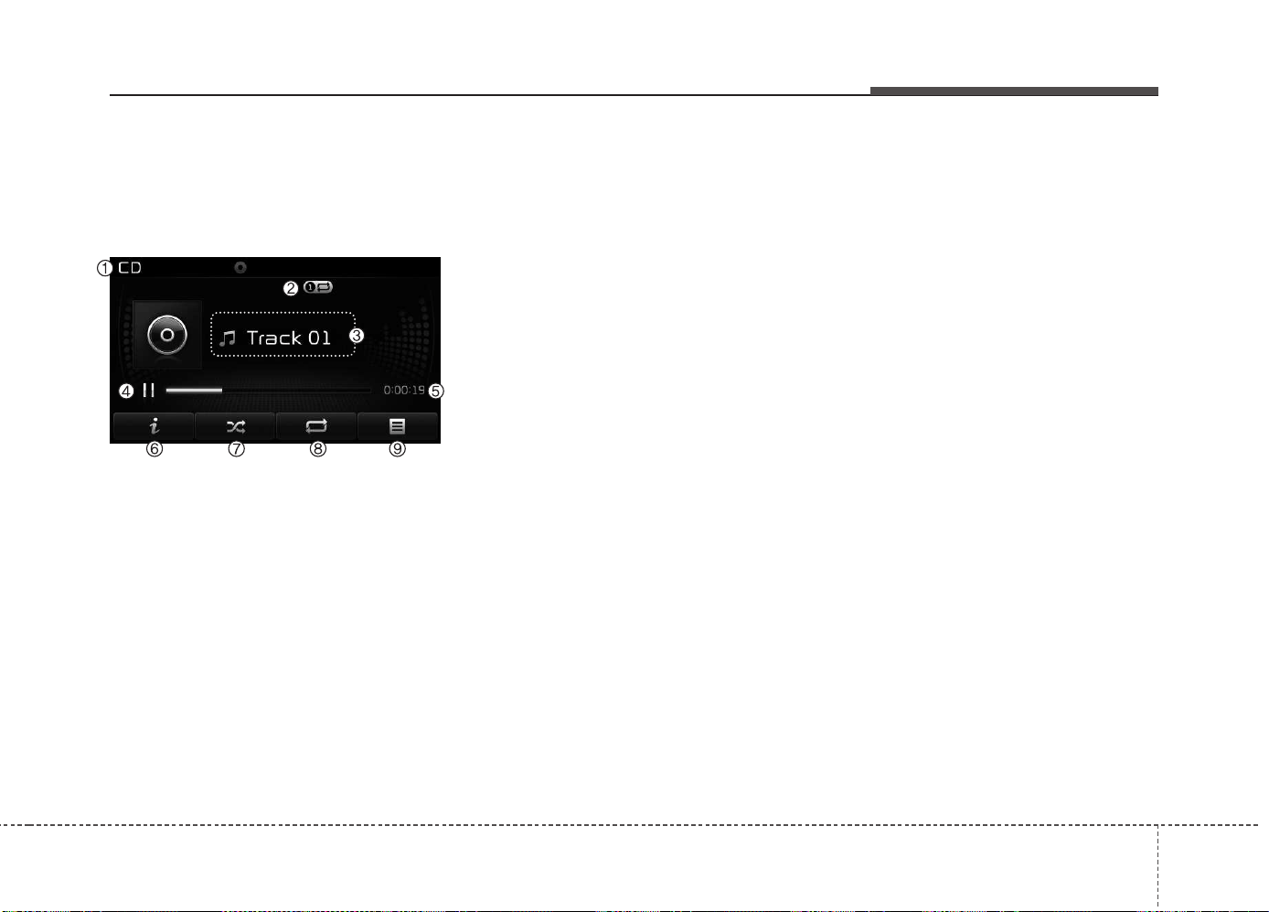
Features of your vehicle
4 241
AUDIO CD MODE
Basic Mode Screen
(1) Mode
Displays currently operating mode.
(2) Operation State
From Repeat/Random/Scan, displays
the currently operating function.
(3) Track Info
Displays information about the cur-
rent track.
(4) Play/Pause
Changes the play/pause state.
(5) Play Time
Displays the current play time.
(6) Info
Shows detailed information about
the current track.
(7) Random
Turns the Random feature on/off.
(8) Repeat
Turns the Repeat feature on/off.
(9) List
Moves to the list screen.
JDB5009LU
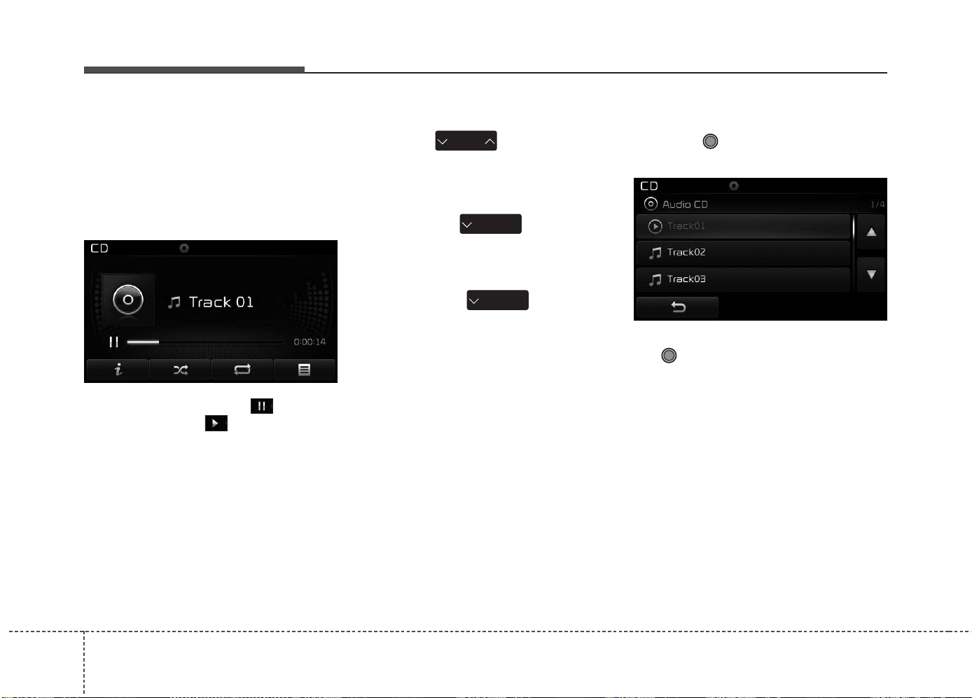
Features of your vehicle
2424
Using Audio CD Mode
Playing/Pausing CD Tracks
Once an audio CD is inserted, the
mode will automatically start and
begin playing.
While playing, press the button to
pause and press button to play.
✽✽
NOTICE
• Only genuine audio CDs are sup-
ported. Other discs may result in
recognition failure (e.g. copy CD-
R, CDs with labels)
• The artist and title information
are displayed on the screen if
track information is included
within the audio CD.
Changing Tracks
Press the key to move to
the previous or next track.
✽✽
NOTICE
• Pressing the key after the
track has been playing for 2 sec-
onds will start the current track
from the beginning.
• Pressing the key before
the track has been playing for 1
second will start the previous track.
Selecting from the List
Turn the TUNE knob left/right to
search for the desired track.
Once you find the desired track, press
the TUNE knob to start playing.
SEEK
TRACK
SEEK
TRACK
SEEK
TRACK
JDB5010LU JDB5011LU
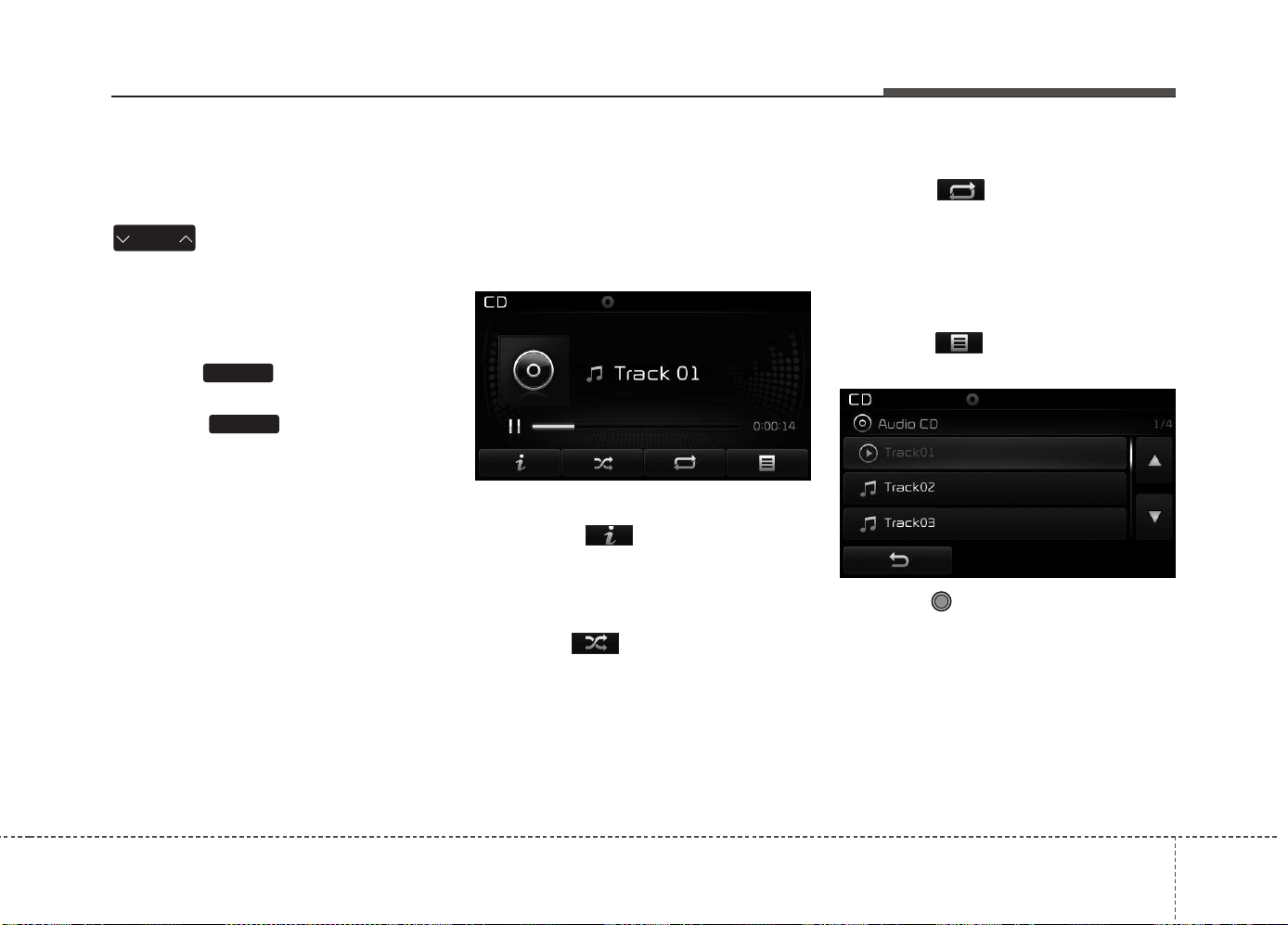
Features of your vehicle
4 243
Rewinding / Fast-forwarding
Tracks
While playing, press and hold the
key (over 0.8 seconds) to
rewind or fast-forward the current
track.
Scan
Press the key to play the first
10 seconds of each file.
Press the key again to turn
off.
Audio CD Mode Menu
Within this mode, you will have
access to the Info, Random, Repeat
and List features.
Info
Press the button to display
details about the current disc.
Random
Press the button to play tracks
in random order.
Press the button again to turn the
Random feature off.
• Random : Plays all tracks in ran-
dom order.
Repeat
Press the button to repeat the
current track. Press the button again
to turn the repeat feature off.
• Repeat: Repeats the current track.
List
Press the button to display the
track list screen.
Turn the TUNE knob left/right to
search for tracks. Once the desired
track is displayed, press the knob to
select and play.
SCAN
SCAN
SEEK
TRACK

Features of your vehicle
2444
MP3 CD MODE
Basic Mode Screen
(1) Mode
Displays currently operating mode.
(2) Operation State
From Repeat/Random/Scan, displays
the currently operating function.
(3) File Index
Displays the current file number.
(4) File Info
Displays information about the cur-
rent file.
(5) Play/Pause
Changes the play/pause state.
(6) Play Time
Displays the current play time.
(7) Info
Shows detailed information about
the current file.
(8) Random
Turns the Random feature on/off.
(9) Repeat
Turns the Repeat feature on/off.
(10) Copy
Copies the current file into My Music.
(11) List
Moves to the list screen.
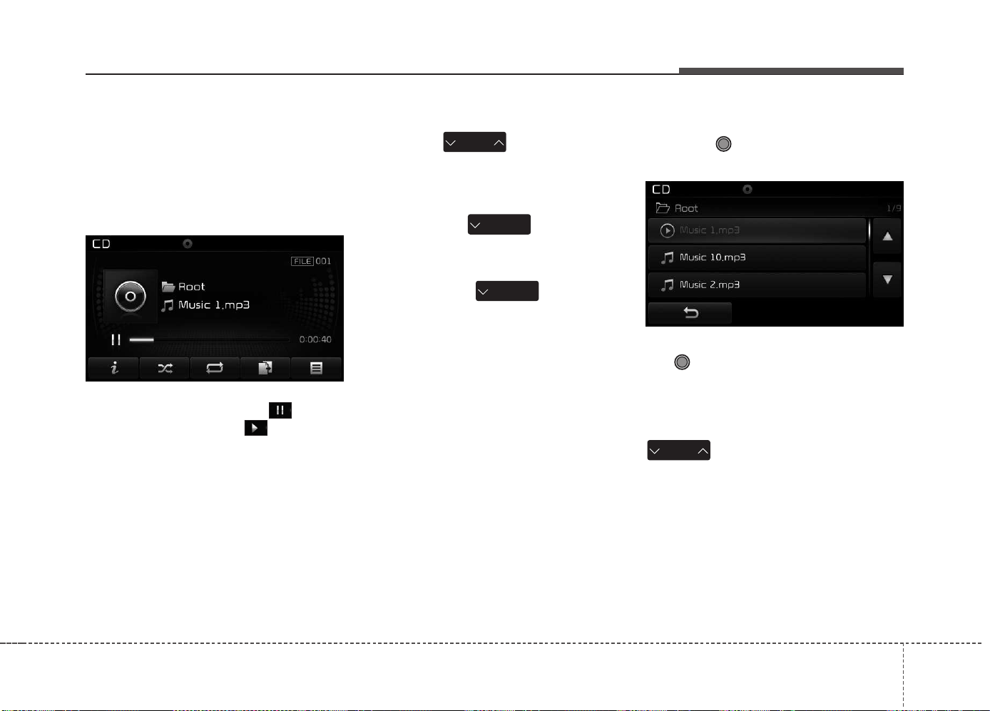
Features of your vehicle
4 245
Using MP3 CD Mode
Playing/Pausing MP3 Files
Once an MP3 disc is inserted the
mode will automatically start and
being playing.
While playing, press the button
to pause and press button to
play.
✽✽
NOTICE
If there are numerous files and fold-
ers within the disc, reading time
could take more than 10 seconds
and the list may not be displayed or
song searches may not operate.
Once loading is complete, try again.
Changing Files
Press the key to move to
the previous or next file.
✽✽
NOTICE
• Pressing the key after the
file has been playing for 2 seconds
will start the current file from the
beginning.
• Pressing the key before
the file has been playing for 1 sec-
ond will start the previous file.
Selecting from the List
Turn the TUNE knob left/right to
search for the desired file.
Once you find the desired file, press
the TUNE knob to start playing.
Rewinding / Fast-forwarding Files
While playing, press and hold the
key (over 0.8 seconds) to
rewind or fast-forward the current file.
SEEK
TRACK
SEEK
TRACK
SEEK
TRACK
SEEK
TRACK
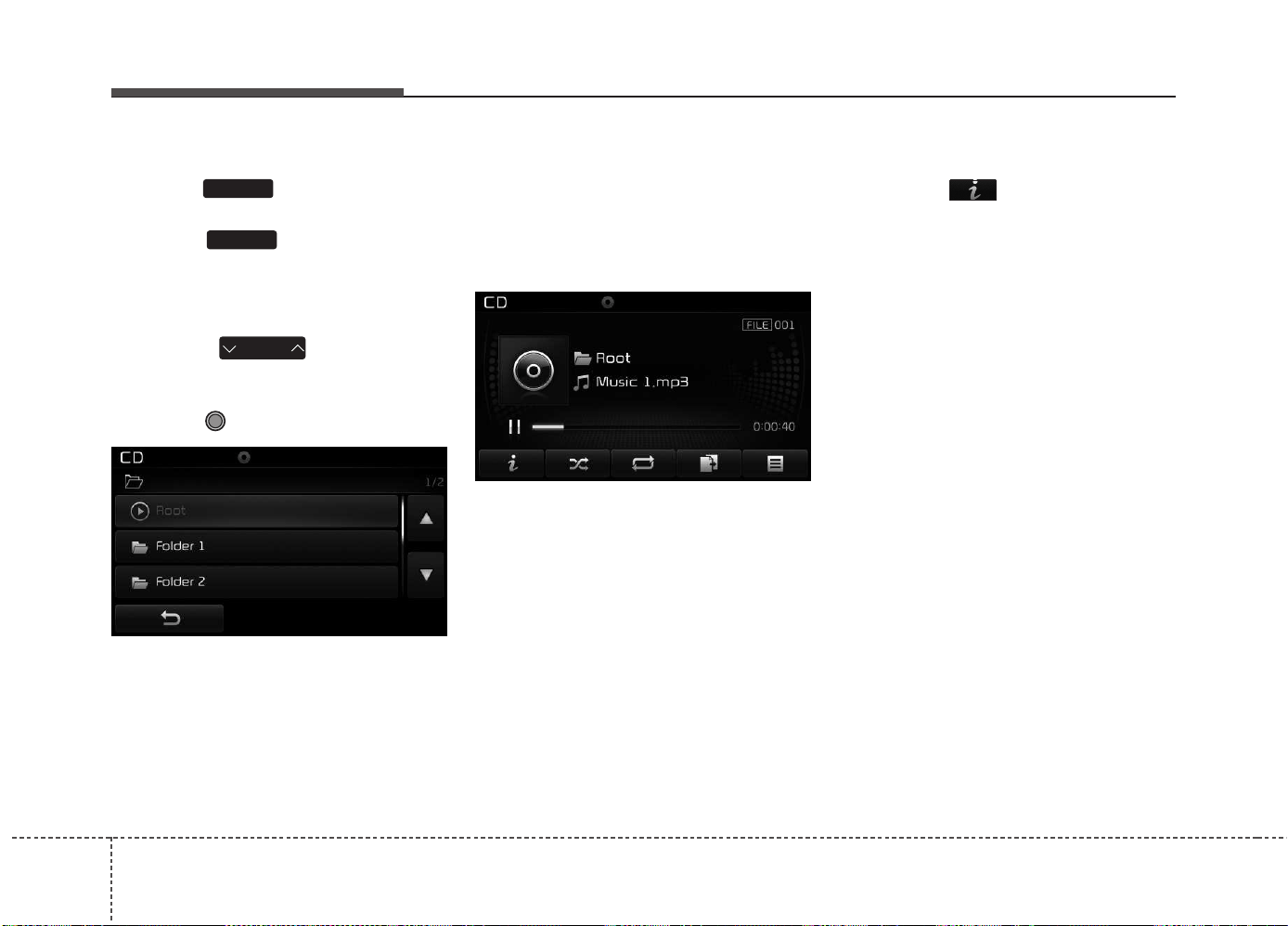
Features of your vehicle
2464
Scan
Press the key to play the first
10 seconds of each file.
Press the key again to turn
off.
Searching Folders
Press the key to select
and search folders.
Once the desired folder is displayed,
press the TUNE knob to select.
The first file within the selected fold-
er will begin playing.
MP3 CD Mode Menu
Within this mode, you will have
access to the Info, Random, Repeat,
Copy and List features.
Info
Press the button to display
details about the current file.
✽✽
NOTICE
• When the ‘Folder File’ option is
set as the default display within
Display setup, the album/artist/file
information are displayed as
detailed file information.
• When the ‘Album Artist Song’
option is set as the default display,
the folder name/file name are dis-
played as detailed file information.
• The title, artist and album info are
displayed only when such infor-
mation are recorded within the
MP3 file ID3 tag.
FOLDER
SCAN
SCAN
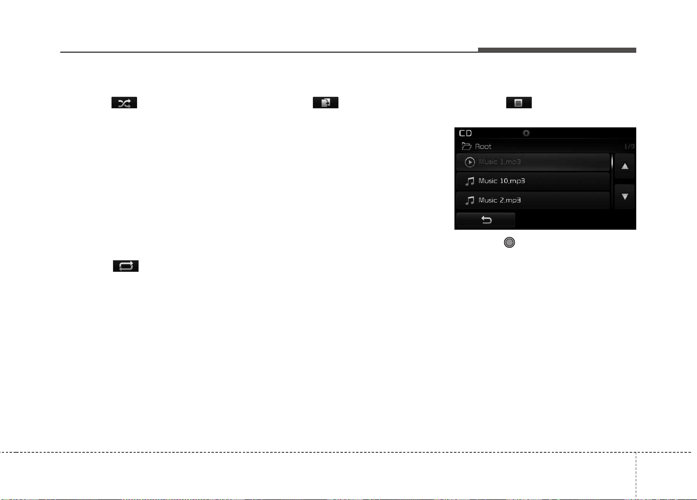
Features of your vehicle
4 247
Random
Press the button to play files in
random order.
Each time the button is pressed, the
feature changes in order of Random
Folder ➟ Random All➟ Off.
• Random Folder : Plays all files
within the current folder in Random
order.
• Random All : Plays all files in
Random order.
Repeat
Press the button to repeat the
current file or folder.
Each time the button is pressed, the
feature changes in order of Repeat
➟Repeat Folder➟Off.
• Repeat: Repeats the current file.
• Repeat Folder: Repeats all files
within the current Folder.
Copying Files
Press the button to copy the
current file into My Music.
✽✽
NOTICE
Selecting another feature during
copying will display a pop-up asking
whether you wish to cancel copying.
To cancel, select 'Yes’.
List
Press the button to display the
file list screen.
Turn the TUNE knob left/right to
search for files. Once the desired file
is displayed, press the knob to select
and play.

Features of your vehicle
2484
✽✽
NOTICE - USING THE USB
DEVICE
• Connect the USB device after
turning on the engine. The USB
device may become damaged if it
is already connected when the
ignition is turned on. The USB
device may not operate properly if
the car ignition is turned on or off
with the USB device connected.
• Heed caution to static electricity
when connecting/disconnecting
USB devices.
• Encoded MP3 Players will not be
recognized when connected as an
external device.
• When connecting an external USB
device, the device may not proper-
ly recognize the USB is in some
states.
• Only products formatted with
byte/sectors under 64Kbyte will be
recognized.
• This device recognizes USB
devices formatted in FAT 12/16/32
file formats. This device does not
recognize files in NTFS file for-
mat.
(Continued)
(Continued)
• Some USB devices may not be sup-
ported due to compatibility issues.
• Avoid contact between the USB
connector with bodily parts or for-
eign objects.
• Repeated connecting/disconnect-
ing of USB devices within short
periods of time may result in prod-
uct malfunction.
• A strange noise may occur when
disconnecting the USB.
• Make sure to connect/disconnect
external USB devices with the
audio power turned off.
• The amount of time required to
recognize the USB device may dif-
fer depending on the type, size or
file formats stored in the USB.
Such differences in time are not
indications of malfunctions.
• The device only supports USB
devices used to play music files.
• USB images and videos are not
supported.
(Continued)
(Continued)
• Do not use the USB I/F to charge
batteries or USB accessories that
generate heat. Such acts may lead
to worsened performance or dam-
age to the device.
• The device may not recognize the
USB device if separately pur-
chased USB hubs and extension
cables are being used. Connect the
USB directly with the multimedia
terminal of the vehicle.
• When using mass storage USB
devices with separate logical
drives, only files saved to the root
drive can be played.
• Files may not properly operate if
application programs are installed
to the USBs.
• The device may not operate nor-
mally if MP3 Players, cellular
phones, digital cameras, or other
electronic devices (USB devices
not recognized as portable disk
drives) are connected with the
device.
(Continued)
Features of your vehicle
4 249
(Continued)
• Charging through the USB may
not work for some mobile devices.
• The device may not support nor-
mal operation when using a USB
memory type besides (Metal
Cover Type) USB Memory.
• The device may not support nor-
mal operation when using formats
such as HDD Type, CF, or SD
Memory.
• The device will not support files
locked by DRM (Digital Rights
Management.)
• USB memory sticks used by con-
necting an Adaptor (SD Type or
CF Type) may not be properly rec-
ognized.
• The device may not operate prop-
erly when using USB HDDs or
USBs subject to connection fail-
ures caused by vehicle vibrations.
(e.g. i-stick type)
(Continued)
(Continued)
• Avoid use of USB
memory products that
can also be used as key
chains or mobile phone
accessories. Use of such products
may cause damage to the USB
jack.
• Connecting an MP3 device or
phone through various channels,
such as AUX/BT or Audio/USB
mode may result in pop noises or
abnormal operation.
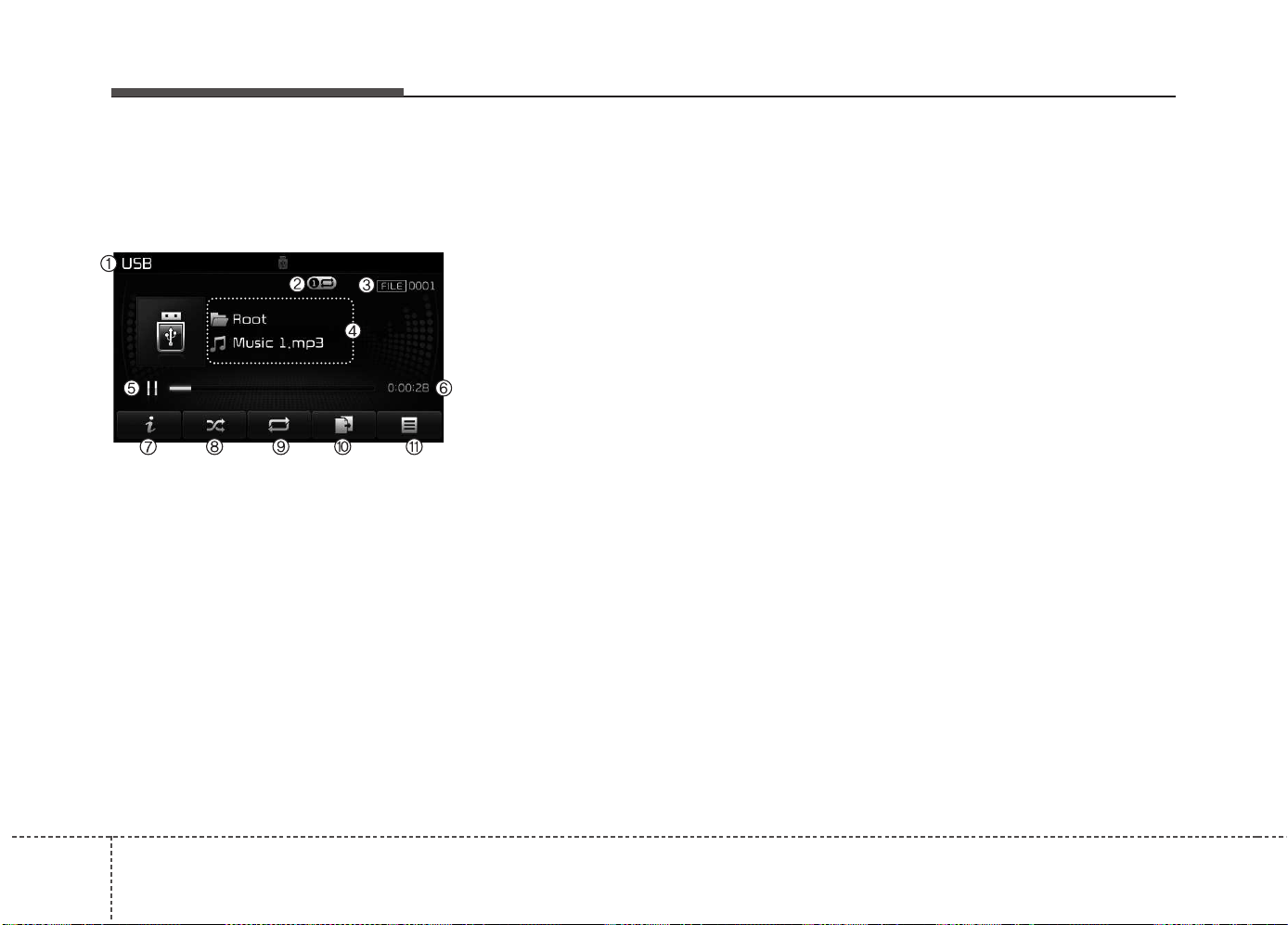
Features of your vehicle
2504
USB MODE
Basic Mode Screen
(1) Mode
Displays currently operating mode.
(2) Operation State
From Repeat/Random/Scan, displays
the currently operating function.
(3) File Index
Displays the current file number.
(4) File Info
Displays information about the cur-
rent file.
(5) Play/Pause
Changes the play/pause state.
(6) Play Time
Displays the current play time.
(7) Info
Displays detailed information for the
current file.
(8) Random
Turns the Random feature on/off.
(9) Repeat
Turns the Repeat feature on/off.
(10) Copy
Copies the current file into My Music.
(11) List
Moves to the list screen.
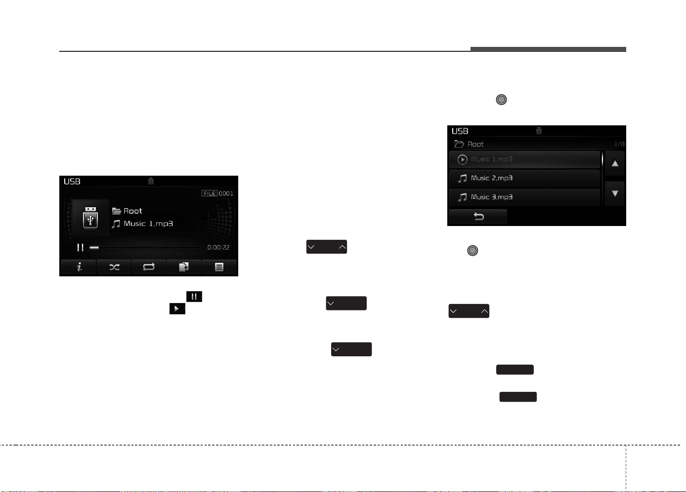
Features of your vehicle
4 251
Using USB Mode
Playing/Pausing USB Files
Once a USB is connected, the mode
will automatically start and begin
playing a USB file.
While playing, press the button
to pause and press button to
play.
✽✽
NOTICE
• Loading may require additional
time if there are many files and
folders within the USB and result
in faulty list display or file search-
ing. Normal operations will
resume once loading is complete.
• The device may not support nor-
mal operation when using a USB
memory type besides (Metal
Cover Type) USB Memory.
Changing Files
Press the keys to move to
the previous or next file.
✽✽
NOTICE
• Pressing the key after the
file has been playing for 2 seconds
will start the current file from the
beginning.
• Pressing the key before
the file has been playing for 1 sec-
ond will start the previous file.
Selecting from the List
Turn the TUNE knob left/right to
search for the desired file.
Once you find the desired file, press
the TUNE knob to start playing.
Rewinding / Fast-forwarding Files
While playing, press and hold the
key (over 0.8 seconds) to
rewind or fast-forward the current file.
Scan
Press the key to play the first
10 seconds of each file.
Press the key again to turn
off.
SCAN
SCAN
SEEK
TRACK
SEEK
TRACK
SEEK
TRACK
SEEK
TRACK
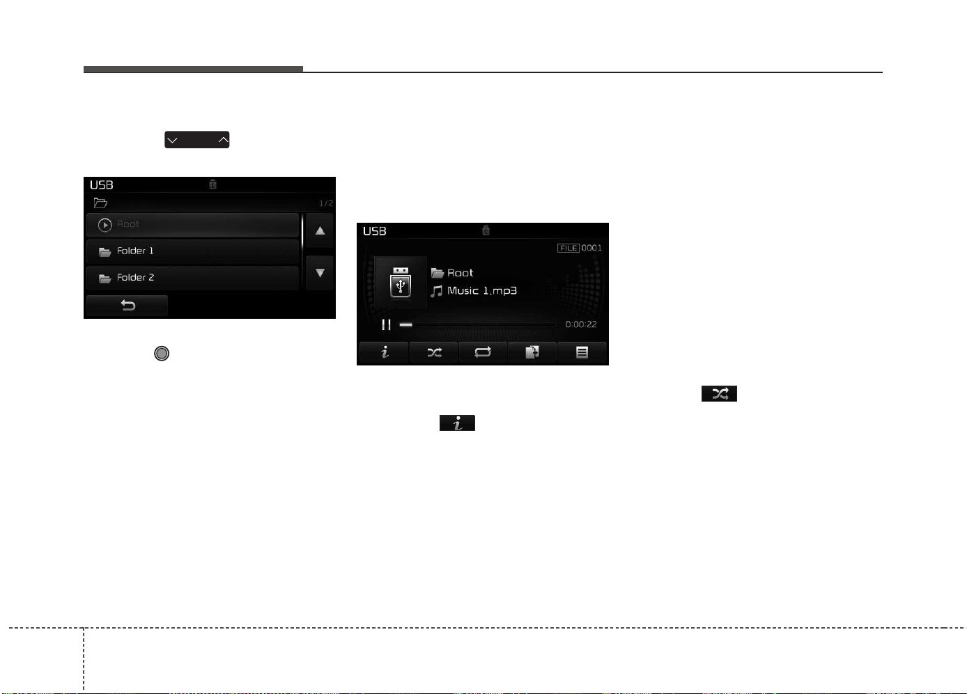
Features of your vehicle
2524
Searching Folders
Press the key to select
and search folders.
Once the desired folder is displayed,
press the TUNE knob to select.
The first file within the selected fold-
er will begin playing.
USB Mode Menu
Within this mode, you will have
access to the Info, Random, Repeat,
Copy and List features.
Info
Press the button to display
details about the current file.
✽✽
NOTICE
• When the ‘Folder File’ option is
set as the default display within
Display setup, the album/artist/file
information are displayed as
detailed file information.
• When the ‘Album Artist Song’
option is set as the default display,
the folder name/file name are dis-
played as detailed file information.
• The title, artist and album info are
displayed only when such infor-
mation are recorded within the
MP3 file ID3 tag.
Random
Press the button to play files in
random order.
Each time the button is pressed, the
feature changes in order of Random
Folder ➟ Random All ➟ Off.
• Random Folder : Plays the files in
the current folder in random order.
• Random All : Plays all files in ran-
dom order.
FOLDER
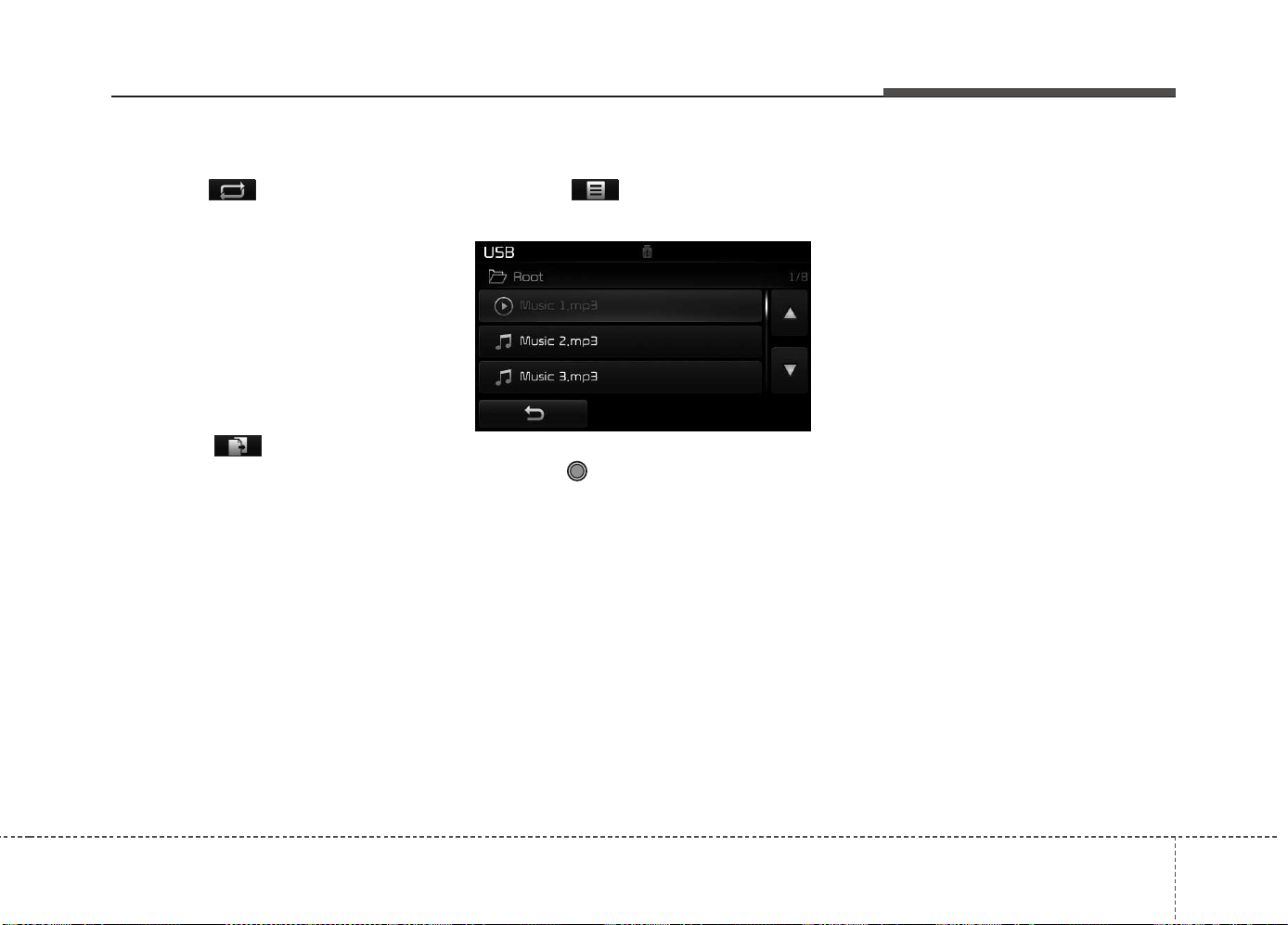
Features of your vehicle
4 253
Repeat
Press the button to repeat the
current file or folder.
Each time the button is pressed, the
feature changes in order of Repeat➟
Repeat Folder ➟ Off.
• Repeat : Repeats the current file.
• Repeat Folder : Repeats all files
within the current folder.
Copying Files
Press the button to copy the
current file into My Music.
✽✽
NOTICE
Selecting another feature during
copying will display a pop-up asking
whether you wish to cancel copying.
To cancel, select “Yes”.
List
Press the button to display the
file list screen.
Turn the TUNE knob left/right to
search for files. Once the desired file
is displayed, press the knob to select
and play.

Features of your vehicle
2544
✽✽
NOTICE - USING THE iPod
®
DEVICE
• iPod
®
is a registered trademark of
Apple Inc.
• In order to use the iPod
®
while
operating the keys, you must use a
dedicated iPod
®
cable. (the cable
that is supplied when purchasing
iPod
®
/iPhone
®
products)
• If the iPod
®
is connected to the
vehicle while it is playing, a high
pitch sound could occur for
approximately 1-2 seconds imme-
diately after connecting. If possi-
ble, connect the iPod
®
to the vehi-
cle with the iPod
®
stopped/paused.
• During ACC ON state, connecting
the iPod
®
through the iPod
®
cable
will charge the iPod
®
through the
car audio system.
• When connecting with the iPod
®
cable, make sure to fully insert the
jack to prevent communication
interference.
(Continued)
(Continued)
• When the EQ features of an exter-
nal device, such as the iPod
®
, and
the audio system are both active,
EQ effects could overlap and cause
sound deterioration and distortion.
Whenever possible, turn off the EQ
feature within the external device
upon use by connecting with the
audio system.
• Noise may occur when an iPod
®
or
AUX device is connected. When
such devices are not being used, dis-
connect the device for storage.
• When the iPod
®
or AUX device
power is connected to the power
jack, playing the external device
may result in noise. In such cases,
disconnect the power connection
before use.
• Skipping or improper operation may
occur depending on the characteris-
tics of your iPod
®
/iPhone
®
device.
• If your iPhone is connected to both
the Bluetooth
®
Wireless Technology
and USB, the sound may not be
properly played. In your iPhone,
select the Dock connector or
Bluetooth
®
Wireless Technology to
change the sound output (source).
(Continued)
(Continued)
• iPod
®
mode cannot be operated
when the iPod
®
cannot be recog-
nized due to the playing of ver-
sions that do not support commu-
nication protocols, cases of iPod
®
abnormalities and defects.
• For fifth generation iPod
®
Nano
devices, the iPod
®
may not be rec-
ognized when the battery level is
low. Please charge the iPod
®
for
use.
• Search/play orders shown within
the iPod
®
device may differ with
the orders shown within the audio
system.
• If the iPod
®
malfunctions due to an
iPod
®
device defect, reset the iPod
®
and try again. (To learn more,
refer to your iPod
®
manual)
• Some iPod
®
s may not sync with the
System depending on its version.
If the Media is removed before the
Media is recognized, then the sys-
tem may not properly restore the
previously operated mode. (iPad
charging is not supported.)
• Beside support 1M cable when
purchasing iPod/iPhone products,
Long Cable cannot be recognized.
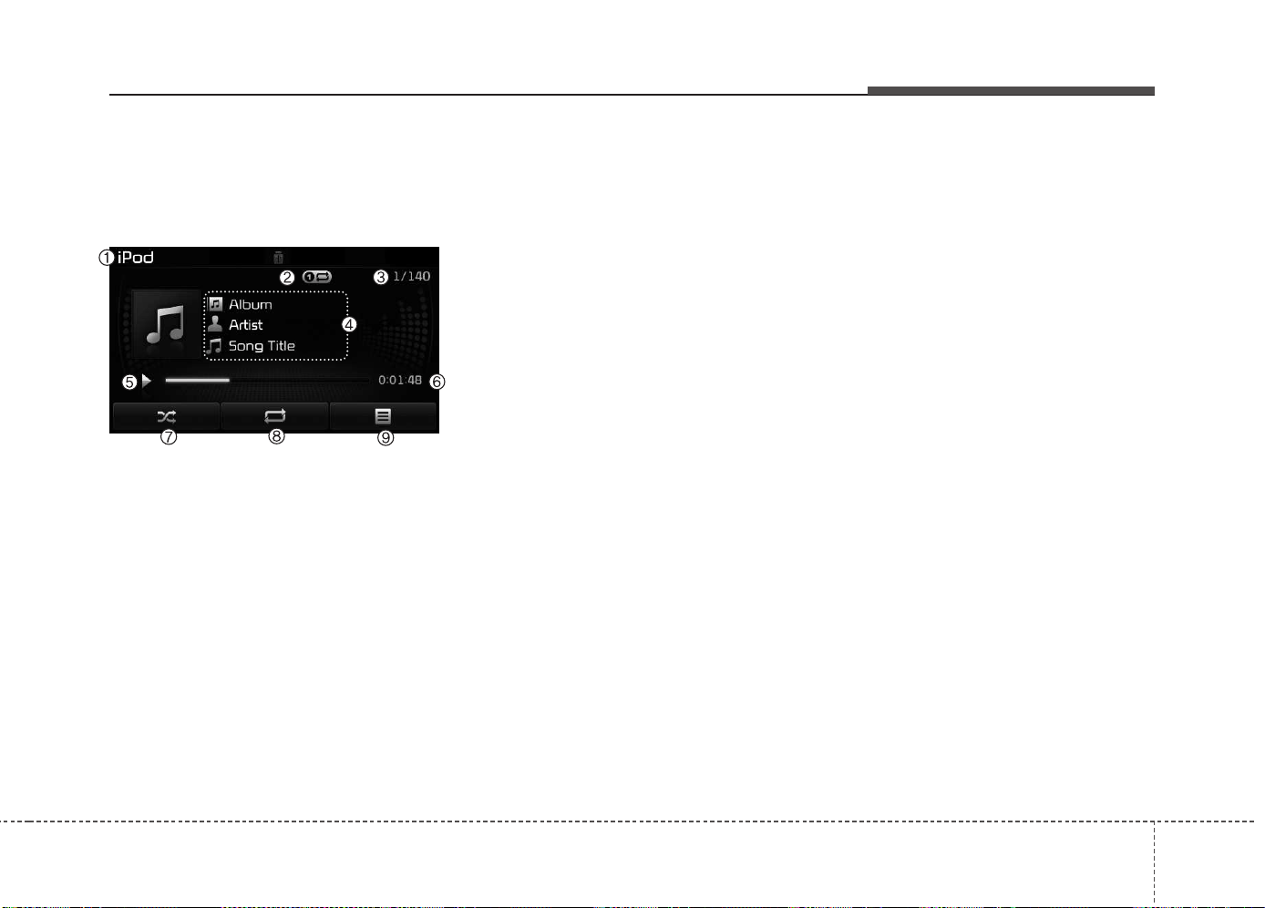
Features of your vehicle
4 255
iPod
®
MODE
Basic Mode Screen
(1) Mode
Displays currently operating mode.
(2) Operation State
From Repeat/Random, displays the
currently operating function.
(3) Song Index
Displays the current song/total num-
ber of songs.
(4) Song Info
Displays information about the cur-
rent song.
(5) Play/Pause
Changes the play/pause state.
(6) Play Time
Displays the current play time.
(7) Random
Turns the Random feature on/off.
(8) Repeat
Turns the Repeat feature on/off.
(9) List
Moves to the list screen.
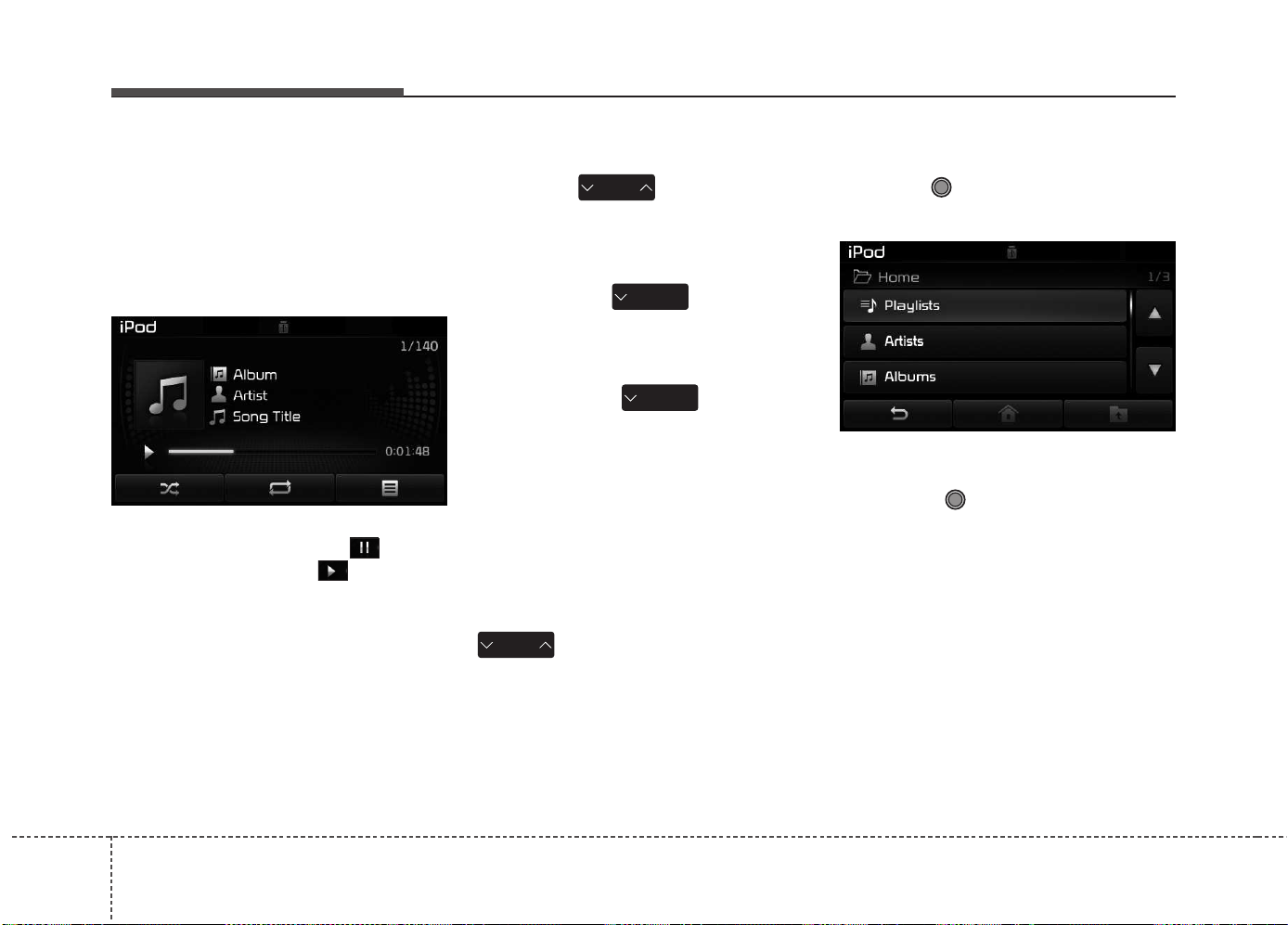
Features of your vehicle
2564
Using iPod
®
Mode
Playing/Pausing iPod
®
Songs
Once an iPod
®
is connected, the
mode will automatically start and
begin playing an iPod
®
song.
While playing, press the button
to pause and press button to
play.
✽✽
NOTICE
iPod
®
s with unsupported communi-
cation protocols may not properly
operate in the audio system.
Changing Songs
Press the key to move to
the previous or next song.
✽✽
NOTICE
• Pressing the key after the
song has been playing for 2 sec-
onds will start the current song
from the beginning.
• Pressing the key before
the song has been playing for 1
second will start the previous
song.
• Slight time differences may exist
depending your iPod
®
product.
Rewinding / Fast-forwarding
Songs
While playing, press and hold the
key (over 0.8 seconds) to
rewind or fast-forward the current
song.
Searching Categories
Turn the TUNE knob left/right to
search for the desired category.
Once you find the desired category,
press the TUNE knob to select
and play.
✽✽
NOTICE
There are eight categories that can be
searched, including Playlists, Artists,
Albums, Genres, Songs, Composers,
Audiobooks and Podcasts.
SEEK
TRACK
SEEK
TRACK
SEEK
TRACK
SEEK
TRACK
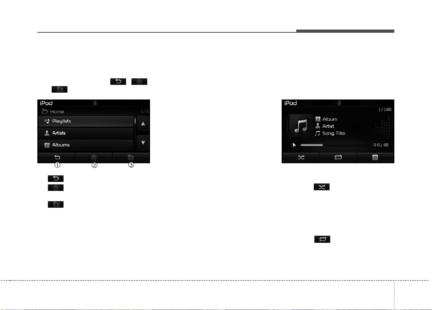
Features of your vehicle
4 257
Category Menu
Within the iPod
®
Category menu, you
will have access to the , ,
and features.
(1) : Displays the play screen
(2) : Moves to the iPod
®
root cat-
egory screen
(3) : Moves to the previous cat-
egory
✽✽
NOTICE
• If the search mode is accessed
while playing a song, the most
recently searched category is dis-
played.
• Search steps upon initial connec-
tion may differ depending on the
type of iPod
®
device.
iPod
®
Mode Menu
Within this mode, you will have
access to the Random, Repeat and
List features.
Random
Press the button to play songs
in random order.
• Random All : Plays all songs in
Random order.
Repeat
Press the button to repeat the
current song. Press the button again
to turn the repeat feature off.
• Repeat : Repeats the current song
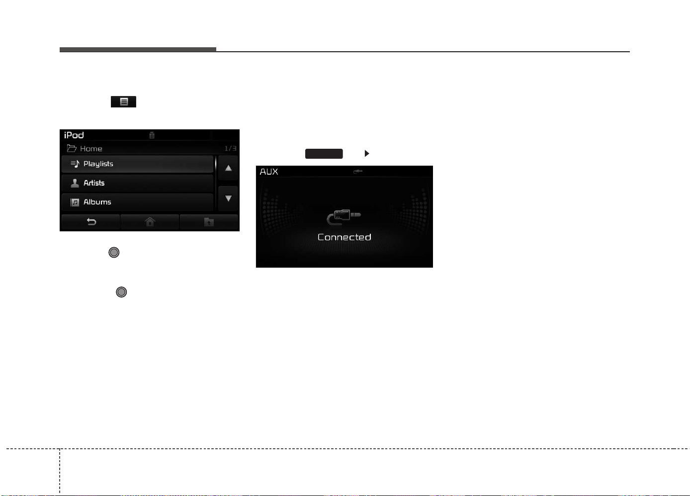
Features of your vehicle
2584
List
Press the button to display the
Category Menu.
Turn the TUNE knob left/right to
search for the desired category.
Once you find the desired category,
press the TUNE knob to select
and play.
AUX MODE
Using AUX Mode
Press the key Select [AUX]
An external device can be connected
to play music.
Connecting an External Device
External audio players (Camcorders,
car VCR, etc.) can be played through
a dedicated cable.
✽✽
NOTICE
• If an external device connector is
connected with the AUX terminal,
then AUX mode will automatically
operate. Once the connector is dis-
connected, the previous mode will
be restored.
• AUX mode can be used only when
an external audio player (cam-
corder, car VCR, etc.) has been
connected.
• The AUX volume can be con-
trolled separately from other
audio modes.
• Connecting a connector jack to the
AUX terminal without an external
device will convert the system to
AUX mode, but only output noise.
When an external device is not
being used, also remove the con-
nector jack.
• When the external device power is
connected to the power jack, play-
ing the external device may output
noise. In such cases, disconnect the
power connection before use.
• Fully insert the AUX cable to the
AUX jack upon use.
MEDIA
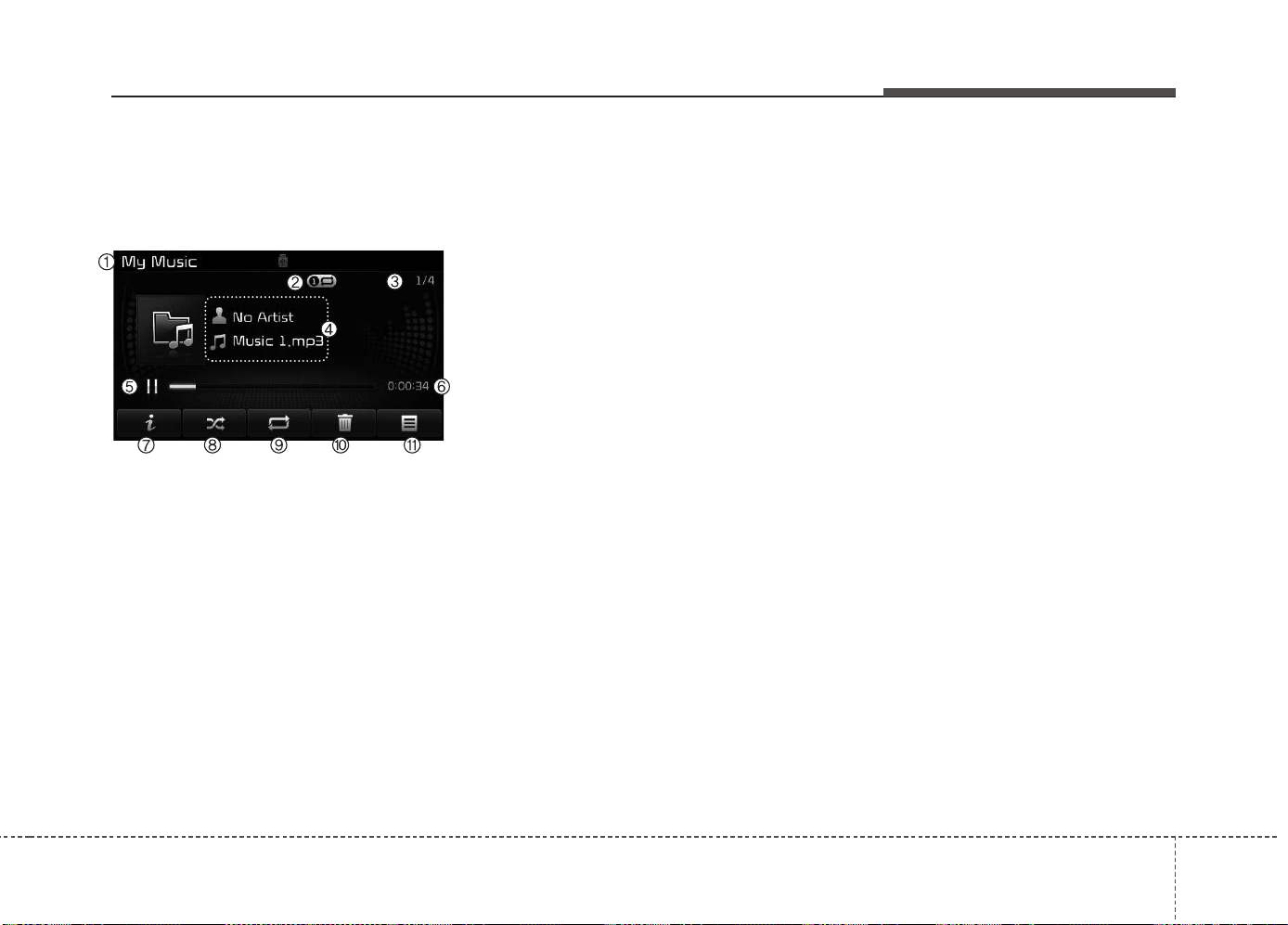
Features of your vehicle
4 259
MY MUSIC MODE
Basic Mode Screen
(1) Mode
Displays currently operating mode.
(2) Operation State
From Repeat/Random/Scan, displays
the currently operating function.
(3) File Index
Displays the current file/total number
of files.
(4) File Info
Displays information about the cur-
rent file.
(5) Play/Pause
Changes the play/pause state.
(6) Play Time
Displays the current play time.
(7) Info
Displays detailed information for the
current file.
(8) Random
Turns the Random feature on/off.
(9) Repeat
Turns the Repeat feature on/off.
(10) Delete
Deletes the current file.
(11) List
Moves to the list screen.
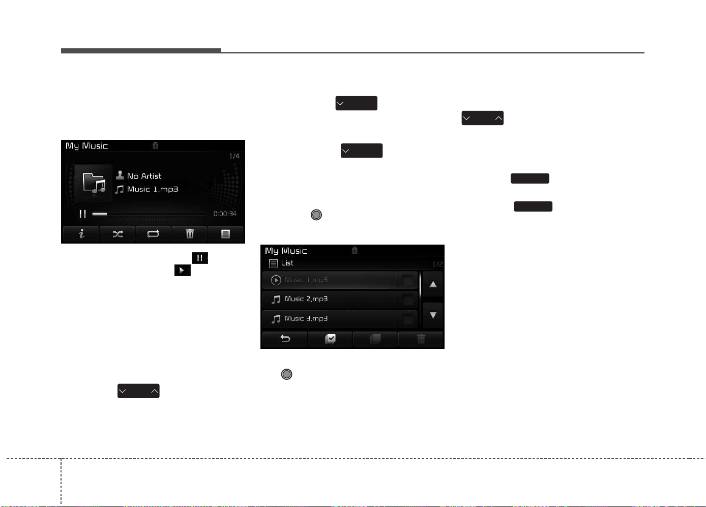
Features of your vehicle
2604
Using My Music Mode
Playing/Pausing My Music Files
While playing, press the button
to pause and press button to
play.
✽✽
NOTICE
If there are no files saved within My
Music, the [My Music] button will
be disabled.
Changing Files
Press the key to move to
the previous or next file.
✽✽
NOTICE
• Pressing the key after the
file has been playing for 2 seconds
will start the current file from the
beginning.
• Pressing the key before
the file has been playing for 1 sec-
ond will start the previous file.
Selecting from the List
Turn the TUNE knob left/right to
search for the desired file.
Once you find the desired file, press
the TUNE knob to start playing.
Rewinding / Fast-forwarding Files
While playing, press and hold the
key (over 0.8 seconds) to
rewind or fast-forward the current file.
Scan
Press the key to play the first
10 seconds of each file.
Press the key again to turn
off.
SCAN
SCAN
SEEK
TRACK
SEEK
TRACK
SEEK
TRACK
SEEK
TRACK
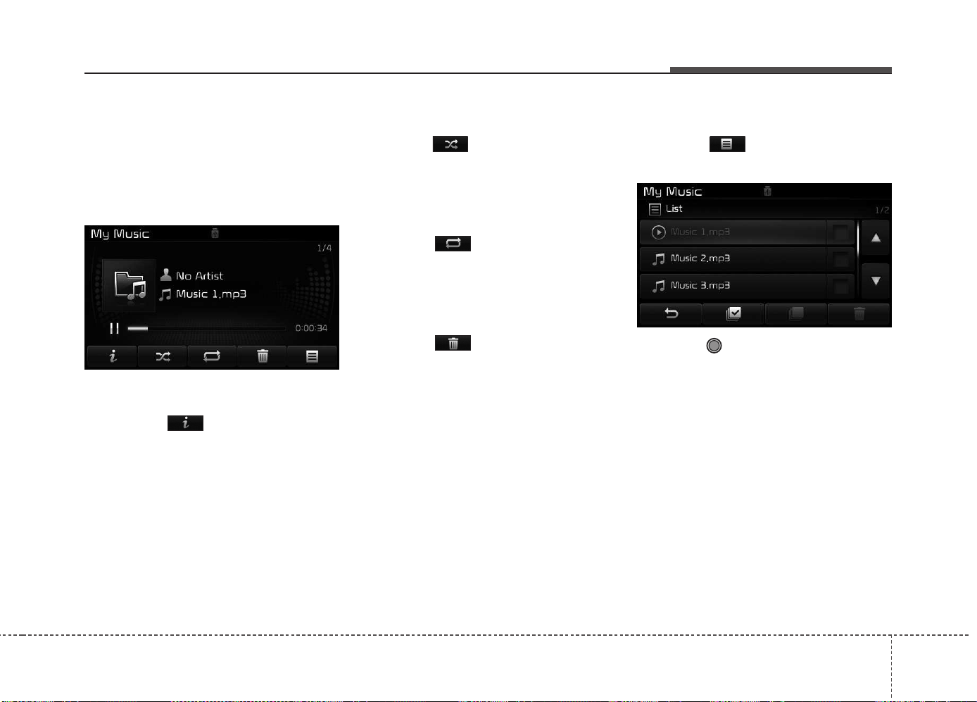
Features of your vehicle
4 261
My Music Mode Menu
Within this mode, you will have
access to the Info, Random, Repeat,
Delete and List features.
Info
Press the button to display
details about the current file.
✽✽
NOTICE
The title, artist and album info are
displayed only when such informa-
tion is recorded within the MP3 file
ID3 tag.
Random
Press the button to play files in
random order. Press the button again
to turn the Random feature off.
Repeat
Press the button to repeat the
current song. Press the button again
to turn the repeat feature off.
Deleting Files
Press the button to delete the
current file.
List
Press the button to display the
file list screen.
Turn the TUNE knob left/right to
search for files. Once the desired file
is displayed, press the knob to select
and play.
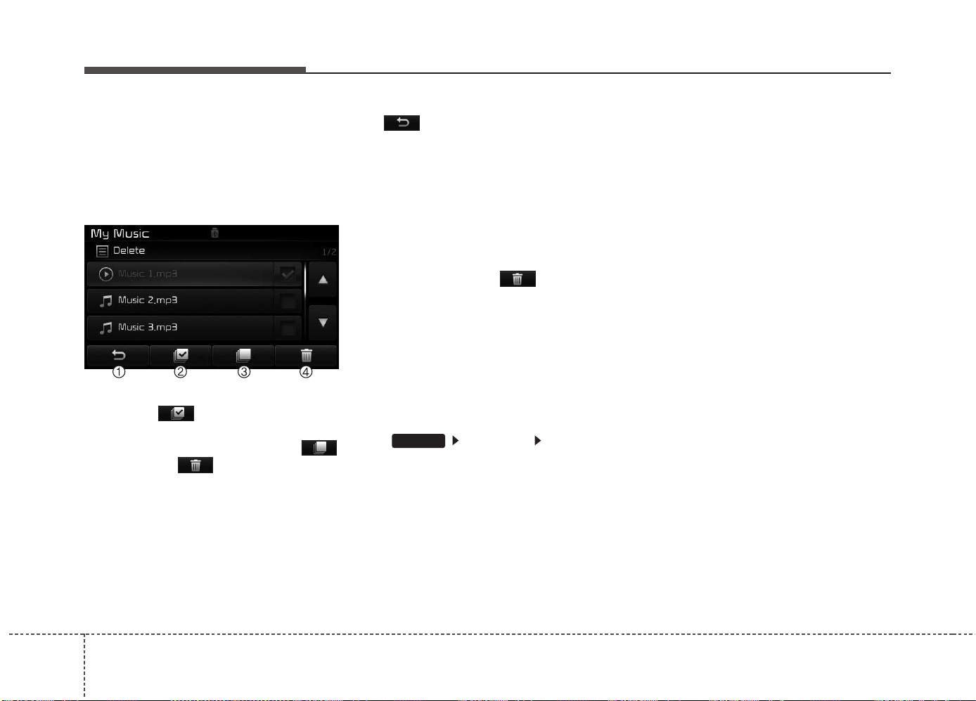
Features of your vehicle
2624
List Menu
From the List screen, it is possible to
delete files you previously saved into
My Music.
Press the button or individual-
ly select the files you want to delete.
Once files are selected, the
button and buttons will be
enabled.
(1) : Moves to the previous
screen
(2) Select All : Selects all files
(3) Unselect All : Deselects all select-
ed files
(4) Delete : Deletes selected files
After selecting the files you want to
delete, press the button to
delete the selected files.
✽✽
NOTICE
• If there is memory available, up to
6,000 files can be saved.
• Identical files cannot be copied
more than 1,000 times.
• To check memory information, go
to [System] [Memory
Information]
✽
✽
NOTICE
- USING THE
Bluetooth
®
Wireless Technology AUDIO
MODE
• Bluetooth
®
Wireless Technology
Audio Mode can be used only when
a Bluetooth
®
Wireless Technology
phone has been connected.
• Bluetooth
®
Wireless Technology
Audio Mode will not be available
when connecting mobile phones
that do not support this feature.
• While Bluetooth
®
Wireless
Technology Audio is playing, if the
Bluetooth
®
Wireless Technology
phone is connected, then the music
will also stop.
• Moving the Track up/down while
playing Bluetooth
®
Wireless
Technology audio mode may
result in pop noises in some mobile
phones.
• Bluetooth
®
Wireless Technology
streaming audio may not be sup-
ported in some mobile phones.
(Continued)
SETUP
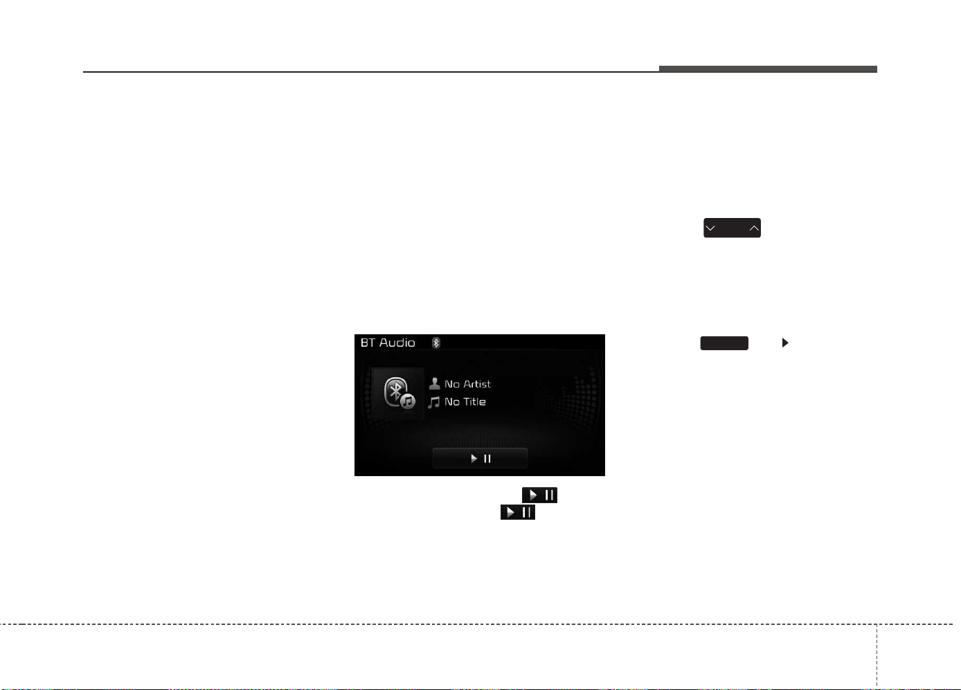
Features of your vehicle
4 263
(Continued)
• When returning to Bluetooth
®
Wireless Technology Audio mode
after ending a call, the mode may
not automatically restart in some
mobile phones.
• Receiving an incoming call or
making an outgoing call while
playing Bluetooth
®
Wireless
Technology Audio may result in
audio interference.
Bluetooth
®
Wireless
Technology AUDIO MODE
Using
Bluetooth
®
Wireless
Technology Audio Mode
Playing/Pausing Bluetooth
®
Wireless Technology
Audio
Once a
Bluetooth
®
Wireless Technology
device is connected, the mode will
automatically start.
While playing, press the button
to pause and press button to
play.
✽✽
NOTICE
The play/pause feature may operate
differently depending on the mobile
phone.
Changing Files
Press the key to move to
the previous or next file.
Setting Connection
If a
Bluetooth
®
Wireless Technology
device has not been connected,
press the key [Phone] but-
ton to display the
Bluetooth
®
Wireless
Technology connection screen.
It is possible to use the pair phone,
connect/disconnect and delete fea-
tures from your
Bluetooth
®
Wireless
Technology phone.
SETUP
SEEK
TRACK

Features of your vehicle
2644
✽✽
NOTICE
If music is not yet playing from your
mobile device after converting to
Bluetooth
®
Wireless Technology
Audio mode, pressing the play but-
ton once may start playing the
mode. Check to see that music is
playing from the Bluetooth
®
Wireless Technology device after
converting to Bluetooth
®
Wireless
Technology Audio Mode.
Bluetooth
®
Wireless Technology
Using
Bluetooth
®
Wireless
Technology Handsfree
•
Bluetooth
®
Wireless Technology
refers to a short-distance wireless
networking technology which uses
a 2.45GHz frequency to connect
various devices within a certain
distance.
• Supported within PCs, external
devices,
Bluetooth
®
Wireless
Technology phones, PDAs, various
electronic devices, and automotive
environments,
Bluetooth
®
Wireless
Technology allows data to be
transmitted at high speeds without
having to use a connector cable.
•
Bluetooth
®
Wireless Technology
Handsfree refers to a device which
allows the user to conveniently
make phone calls with
Bluetooth
®
Wireless Technology mobile
phones through the audio system.
CAUTION
• Bluetooth
®
Wireless Technology
Handsfree is a feature that
enables drivers to practice safe
driving. Connecting the car
audio system with a Bluetooth
®
Wireless Technology phone
allows the user to conveniently
make calls, receive calls, and
manage the phone book. Before
using the Bluetooth
®
Wireless
Technology , carefully read the
contents of this user’s manual.
• Excessive use or operations
while driving may lead to negli-
gent driving practices and be
the cause of accidents.
• Do not operate the device
excessively while driving.
• Viewing the screen for pro-
longed periods of time is dan-
gerous and may lead to acci-
dents. When driving, view the
screen only for short periods of
time.

Features of your vehicle
4 265
✽✽
NOTICE - USING UPONCON-
NECTING
Bluetooth
®
Wireless Technology
PHONE
• Before connecting the car audio
system with the mobile phone,
check to see that the mobile phone
supports Bluetooth
®
Wireless
Technology features.
• Even if the phone supports
Bluetooth
®
Wireless Technology,
the phone will not be found during
device searches if the phone has
been set to hidden state or the
Bluetooth
®
Wireless Technology
power is turned off. Disable the
hidden state or turn on the
Bluetooth
®
Wireless Technology
power prior to searching/connect-
ing with the car audio system.
(Continued)
(Continued)
• If you do not want to automatical-
ly connect your Bluetooth
®
Wireless Technology phone, try
the following.
1. Turn off the Bluetooth
®
Wireless
Technology feature in your
mobile phone.
- For more information on
Bluetooth
®
Wireless Technology
features within your mobile,
refer to your mobile phone
user’s manual.
2. Turn off the Bluetooth
®
Wireless
Technology feature in your car
audio system.
- To turn off the Bluetooth
®
Wireless
Technology feature in your car
audio system, go to
[Phone] and [turn off] the
Bluetooth
®
Wireless Technology
feature.
• Park the vehicle when connecting
the car audio system with your
mobile phone.
(Continued)
(Continued)
• Bluetooth
®
Wireless Technology
connection may become intermit-
tently disconnected in some
mobile phones. Follow these steps
to try again.
1. Turn the Bluetooth
®
Wireless
Technology function within the
mobile phone off/on and try
again.
2. Turn the mobile phone power
Off/On and try again.
3. Completely remove the mobile
phone battery, reboot, and then
again.
4. Reboot the audio system and
try again.
5. Delete all paired devices, pair
and try again.
• The Handsfree call volume and
quality may differ depending on
the mobile phone.
(Continued)
SETUP

Features of your vehicle
2664
(Continued)
• Bluetooth
®
Wireless Technology
features supported within the
vehicle are as follows. Some fea-
tures may not be supported
depending on your Bluetooth
®
Wireless Technology device.
-Answering and placing Bluetooth
®
Wireless Technology Handsfree
calls
-Menu operation during call
(Switch to Private, Switch to call
waiting, Outgoing volume)
-Download Call History
-Download Mobile Phone book
-Phone book/Call History Auto
Download
-Bluetooth
®
Wireless Technology
device auto connection
-Bluetooth
®
Wireless Technology
Audio
• It is possible to pair up to five
Bluetooth
®
Wireless Technology
devices to the car system.
• Only one Bluetooth
®
Wireless
Technology device can be connect-
ed at a time.
(Continued)
(Continued)
• Other devices cannot be paired while
a Bluetooth
®
Wireless Technology
device is already connected.
• When a Bluetooth
®
Wireless
Technology device is being con-
nected, the connection process
cannot be canceled.
• Only Bluetooth
®
Wireless Technology
Handsfree and Bluetooth
®
Wireless
Technology audio related features will
operate within this system.
• Normal operation is possible only
for devices that support Handsfree
or audio features, such as a
Bluetooth
®
Wireless Technology
mobile phone or a Bluetooth
®
Wireless Technology audio device.
• Only one function can be used at a
time between the Bluetooth
®
Wireless Technology Handsfree
and Bluetooth
®
Wireless Technology
audio. (While playing Bluetooth
®
Wireless Technology audio,
streaming will end upon entering
the Bluetooth
®
Wireless Technology
phone screen.)
(Continued)
(Continued)
• If a connected Bluetooth
®
Wireless
Technology device becomes dis-
connected for various reasons,
such as being out of range, turning
the device OFF, or a Bluetooth
®
Wireless Technology communica-
tion error, Bluetooth
®
Wireless
Technology devices are automati-
cally searched and connected.
• Placing the audio system within an
electromagnetic environment may
result in noise interference.
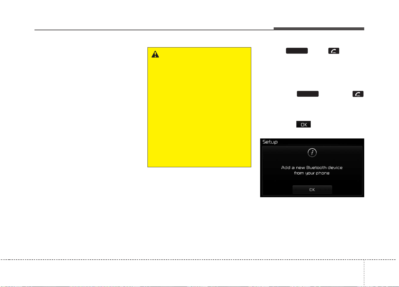
Features of your vehicle
4 267
Bluetooth
®
Wireless Technology
Pairing a
Bluetooth
®
Wireless
Technology Device
What is
Bluetooth
®
Wireless
Technology Pairing?
Pairing refers to the process of syn-
chronizing your
Bluetooth
®
Wireless
Technology phone or device with the
car audio system for connection.
Pairing is necessary to connect and
use the
Bluetooth
®
Wireless
Technology feature.
The Bluetooth
®
word mark and logos
are registered trademarks owned by
Bluetooth SIG, Inc. and any use of
such marks by Kia is under license.
Other trademarks and trade names
are those of their respective owners.
A Bluetooth
®
enabled cell phone is
required to use
Bluetooth
®
Wireless
Technology.
Pairing key / key
on the Steering Remote
Controller
When No Devices have been
Paired
1. Press the key or the
key on the steering remote con-
troller. The following screen is dis-
played.
2. Press the button to enter the
Pair Phone screen.
PHONE
PHONE
WARNING
Driving while distracted can
result in a loss of vehicle control
that may lead to an accident,
severe personal injury, and
death. The driver’s primary
responsibility is in the safe and
legal operation of a vehicle, and
use of any handheld devices,
other equipment, or vehicle sys-
tems which take the driver’s
eyes, attention and focus away
from the safe operation of a vehi-
cle or which are not permissible
by law should never be used dur-
ing operation of the vehicle.
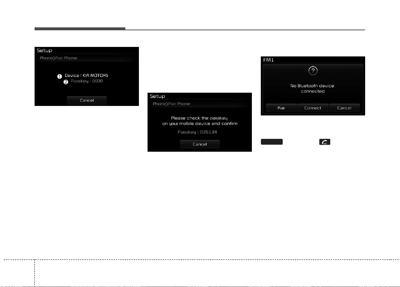
Features of your vehicle
2684
(1) Device : Name of device as
shown when searching from your
Bluetooth
®
Wireless Technology
device
(2) Passkey : Passkey used to pair
the device
3. From your
Bluetooth
®
Wireless
Technology device (i.e. Mobile
Phone), search and select your
car audio system.
[Non SSP supported device]
(SSP: Secure Simple Pairing)
4. After a few moments, a screen is
displayed where the passkey is
entered.
Enter the passkey “0000” to pair
your
Bluetooth
®
Wireless
Technology device with the car
audio system.
[SSP supported device]
4. After a few moments, a screen is dis-
played 6 digits passkey.
Check the passkey on your
Bluetooth
®
Wireless Technology
device and confirm.
5. Once pairing is complete, the fol-
lowing screen is displayed.
Some phones (i.e., iPhone
®
, Android
and Blackberry phones) may offer an
option to allow acceptance of all
future Bluetooth connection requests
by default." and "Visit http://www.kia.
com/#/bluetooth for additional infor-
mation on pairing your Bluetooth-
enabled mobile phone, and to view a
phone compatibility list.
✽✽
NOTICE
If Bluetooth
®
Wireless Technology
devices are paired but none are cur-
rently connected, pressing the
key or the key on the
steering wheel displays the following
screen. Press the [Pair] button to
pair a new device or press the
[Connect] to connect a previously
paired device.
PHONE
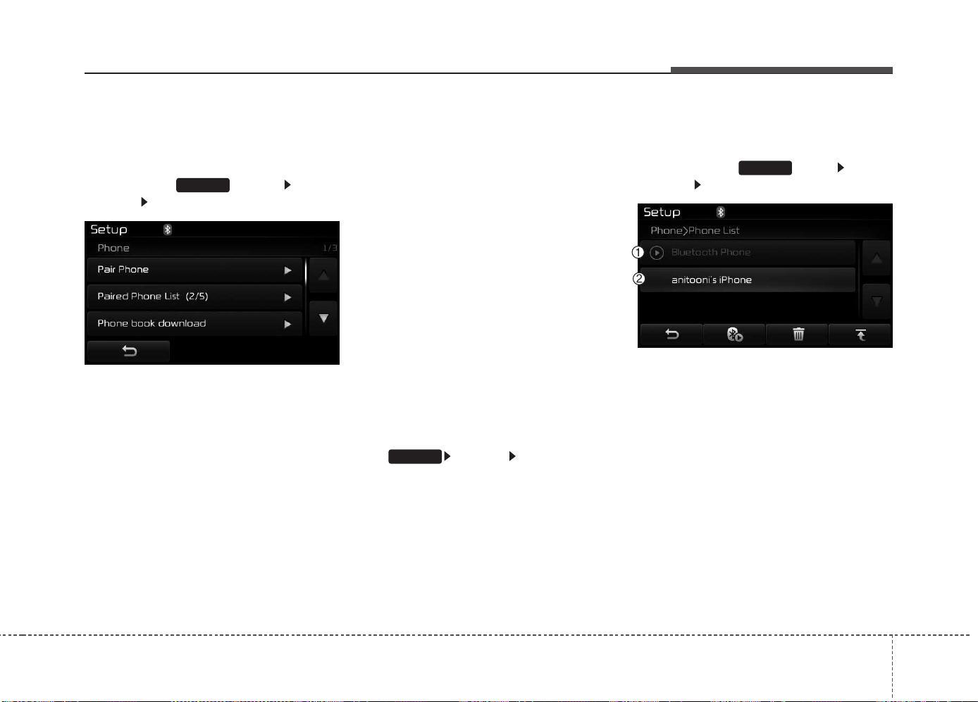
Features of your vehicle
4 269
Pairing through [PHONE]
Setup
Press the key Select
[Phone] Select [Pair Phone]
The following steps are the same as
those described in the section "When
No Devices have been Paired" on the
previous page.
✽✽
NOTICE
• The waiting period during phone
pairing will last for one minute.
The pairing process will fail if the
device is not paired within the
given time. If the pairing process
fails, you must start the process
from the beginning.
• Generally, most Bluetooth
®
Wireless Technology devices will
automatically connect once pair-
ing is complete. However, some
devices may require a separate
verification process to connect.
Check to see whether Bluetooth
®
Wireless Technology has been
properly connected within your
mobile phone.
• List of paired Bluetooth
®
Wireless
Technology devices can be viewed
at [Phone] [Paired Phone
List].
Connecting a Device
Press the key Select
[Phone] Select [Paired Phone List]
(1) Connected Phone : Device that is
currently connected
(2) Paired Phone : Device that is
paired but not connected
SETUP
SETUP
SETUP
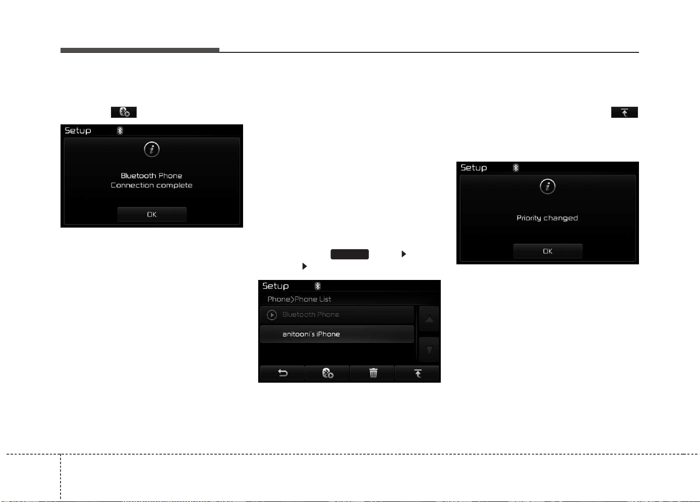
Features of your vehicle
2704
From the paired phone list, select the
device you want to connect and
press the button.
Changing Priority
What is Priority?
It is possible to pair up to five
Bluetooth
®
Wireless Technology
devices with the car audio system.
The "Change Priority" feature is used
to set the connection priority of
paired phones. However, the most
recently connected phone will always
be set as the highest priority.
Press the key Select
[Phone] Select [Paired Phone List]
From the paired phone list, select
the phone you want to switch to the
highest priority, then press the
button from the Menu. The selected
device will be changed to the high-
est priority.
✽✽
NOTICE
When a device is currently connected,
even if you change the priority to a
different device, the currently con-
nected phone will always be set as the
highest priority.
SETUP
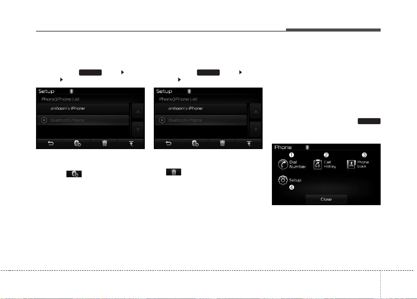
Features of your vehicle
4 271
Disconnecting a Device
Press the key Select
[Phone] Select [Paired Phone List]
From the paired phone list, select the
currently connected device and
press the button.
Deleting a Device
Press the key Select
[Phone] Select [Paired Phone List]
From the paired phone list, select the
device you want to delete and press
the button.
✽✽
NOTICE
• When deleting the currently con-
nected device, the device will auto-
matically be disconnected to pro-
ceed with the deleting process.
• If a paired Bluetooth
®
Wireless
Technology device is deleted, the
device’s call history and phone
book data will also be deleted.
• To re-use a deleted device, you
must pair the device again.
USING
Bluetooth
®
Wireless
Technology
Phone Menu Screen
Phone Menus
With a
Bluetooth
®
Wireless Technology
device connected, press the
key to display the Phone menu
screen.
(1) Dial Number : Displays the dial
screen where numbers can be
dialed to make calls
(2) Call History : Displays the call his-
tory list screen
PHONE
SETUPSETUP
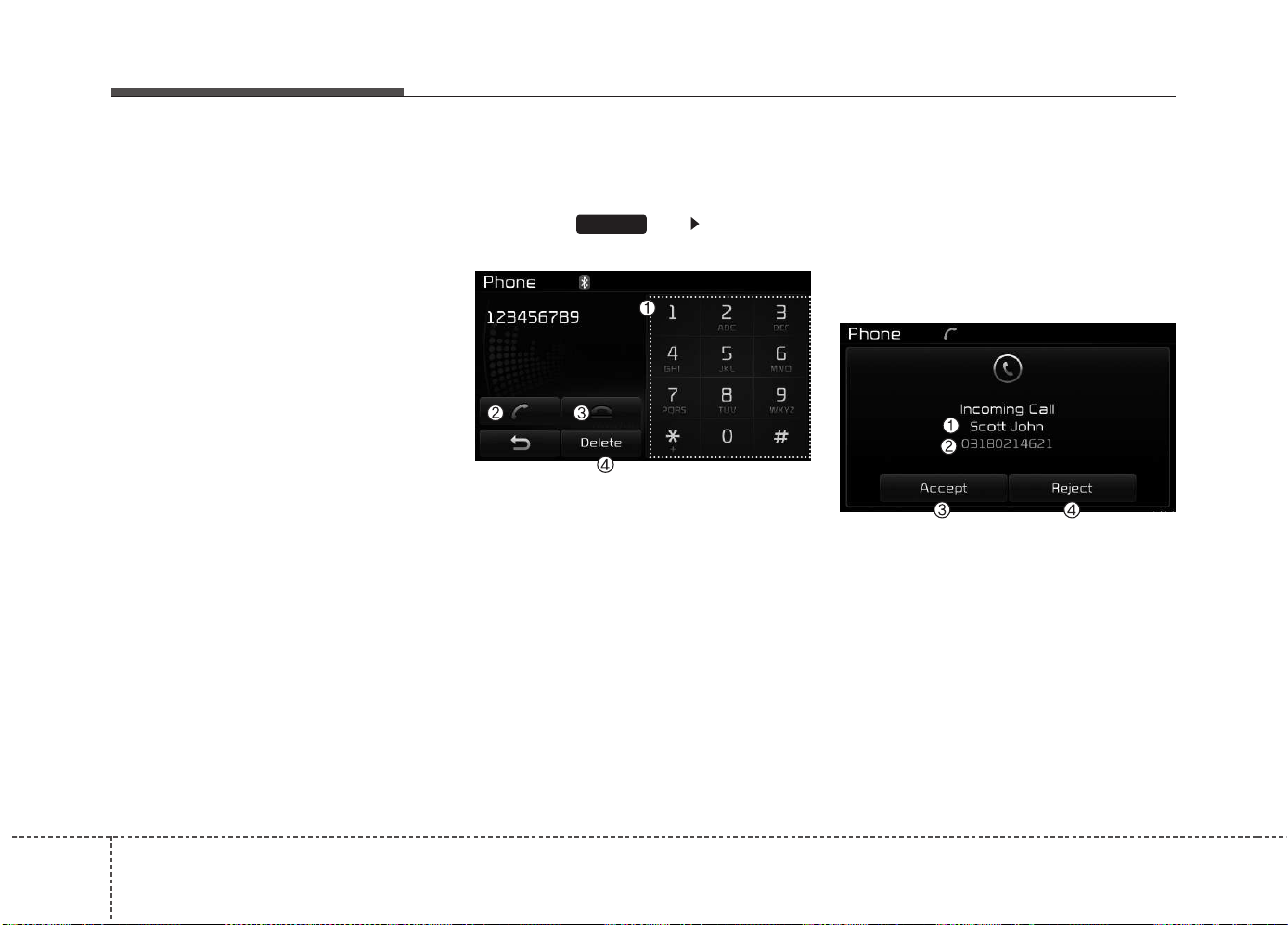
Features of your vehicle
2724
(3) Phone book : Displays the Phone
book list screen
(4) Setup : Displays Phone related
settings
✽✽
NOTICE
• If you press the [Call History] but-
ton but there is no call history
data, a prompt is displayed which
asks whether to download call his-
tory data.
• If you press the [Phone book] but-
ton but there is no phone book
data, a prompt is displayed which
asks whether to download phone
book data.
• This feature may not be supported
in some mobile phones. For more
information on download support,
refer to your mobile phone user’s
manual.
Calling by Dialing a Number
Press the key Select [Dial
Number]
(1) Dial Pad : Used to enter phone
number
(2) Call : If a number has been
entered, calls the number If no
number has been entered,
switches to call history screen
(3) End : Deletes the entered phone
number
(4) Delete : Deletes entered numbers
one digit at a time
Answering Calls
Answering a Call
Answering a call with a
Bluetooth
®
Wireless Technology device connect-
ed will display the following screen.
(1) Caller : Displays the other party’s
name when the incoming caller is
saved within your phone book
(2) Incoming Number : Displays the
incoming number
(3) Accept : Accepts the incoming
call
(4) Reject : Rejects the incoming call
PHONE
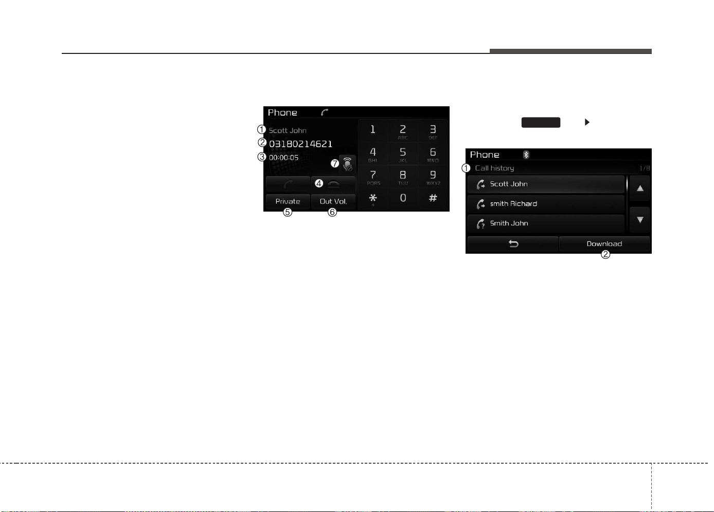
Features of your vehicle
4 273
✽✽
NOTICE
• When an incoming call pop-up is
displayed, most Audio and SETUP
mode features are disabled. Only
the call volume will operate.
• The telephone number may not be
properly displayed in some mobile
phones.
• When a call is answered with the
mobile phone, the call mode will
automatically revert to Private
mode.
During a Handsfree Call
(1) Caller : Displays the other party’s
name if the incoming caller is
saved within your phone book
(2) Incoming Number : Displays the
incoming number
(3) Call time : Displays the call time
(4) End : Ends call
(5) Private : Converts to Private mode
(6) Out Vol. : Sets call volume as
heard by the other party
(7) Mute : Turns Mic Mute On/Off
✽✽
NOTICE
If the mic is muted, the other party
will not be able to hear your voice.
Call History
Press the key Select [Call
History]
A list of incoming, outgoing and
missed calls is displayed.
Press the [Download] button to
download the call history.
(1) Call History :
- Displays recent calls (call history)
- Connects call upon selection
(2) Download : Download Recent
Call History
PHONE
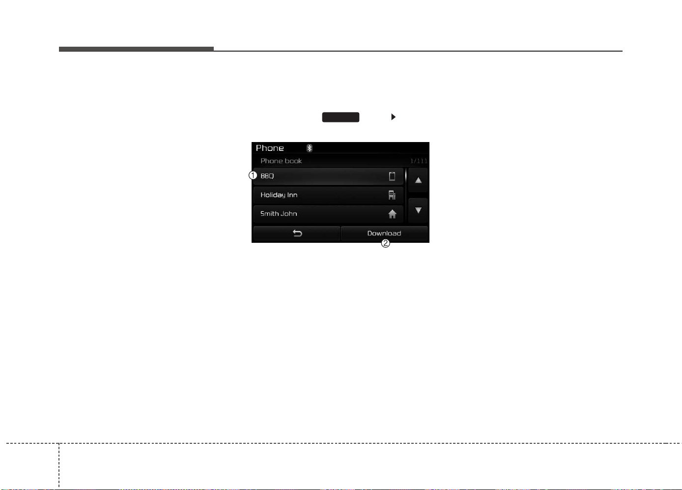
Features of your vehicle
2744
✽✽
NOTICE
• The call history list will display up
to 50 outgoing, incoming, and
missed calls.
• Upon downloading call histories,
previously saved histories are
deleted.
• Incoming calls with hidden caller
IDs will not be saved in the call
history list.
• Previously saved phone book
entries are stored even if a device
is disconnected and re-connected.
• The download feature may not be
supported in some mobile phones.
Check to see that the Bluetooth
®
Wireless Technology device sup-
ports the download feature.
Phone Book
Press the key Select
[Phone book]
The list of saved phone book entries
is displayed. Press the [Download]
button to download the call history.
(1) Contact List :
- Displays downloaded phone book
entries
- Connects call upon selection
(2) Download : Download phone
book entries
✽✽
NOTICE
• Up to 1,000 phone book entries
can be copied into car phone book.
• Upon downloading phone book
data, previously saved phone book
data will be deleted.
• Downloading is not possible if the
phone book download feature is
turned off within the Bluetooth
®
Wireless Technology device. Also,
some devices may require device
authorization upon attempting to
download. If downloading cannot
be normally conducted, check the
Bluetooth
®
Wireless Technology
device setting or the screen state.
• Caller ID information will not be
displayed for unsaved callers.
• The download feature may not be
supported in some mobile phones.
Check to see that the Bluetooth
®
Wireless Technology device sup-
ports the download feature.
PHONE

Features of your vehicle
4 275
✽✽
NOTICE - USING THE VOICE
RECOGNITION
• When using the voice recognition
feature, only commands listed
within the user's manual are sup-
ported.
• Be aware that during the opera-
tion of the voice recognition sys-
tem, pressing any key other than
the key or touching the screen
will terminate voice recognition
mode.
• For superior voice recognition
performance, position the micro-
phone used for voice recognition
above the head of the driver’s seat
and maintain a proper position
when saying commands.
• Within the following situations,
voice recognition may not function
properly due to external sound.
- When the windows and sunroof
are open
- When the wind of the cooling /
heating device is strong
- When entering and passing
through tunnels
- When driving on tgged and
uneven roads
(Continued)
(Continued)
- During severe rain (heavy rains,
windstorms)
• Phone related voice commands
can be used only when a
Bluetooth
®
Wireless Technology
device is connected.
• When making calls by stating a
name, the corresponding contact
must be downloaded and stored
within the audio system.
• After downloading the Bluetooth
®
Wireless Technology phone book,
it takes some times to convert the
phone book data into voice infor-
mation. During this time, voice
recognition may not properly
operate.
• Pronounce the voice commands
naturally and clearly as if in a nor-
mal conversation.
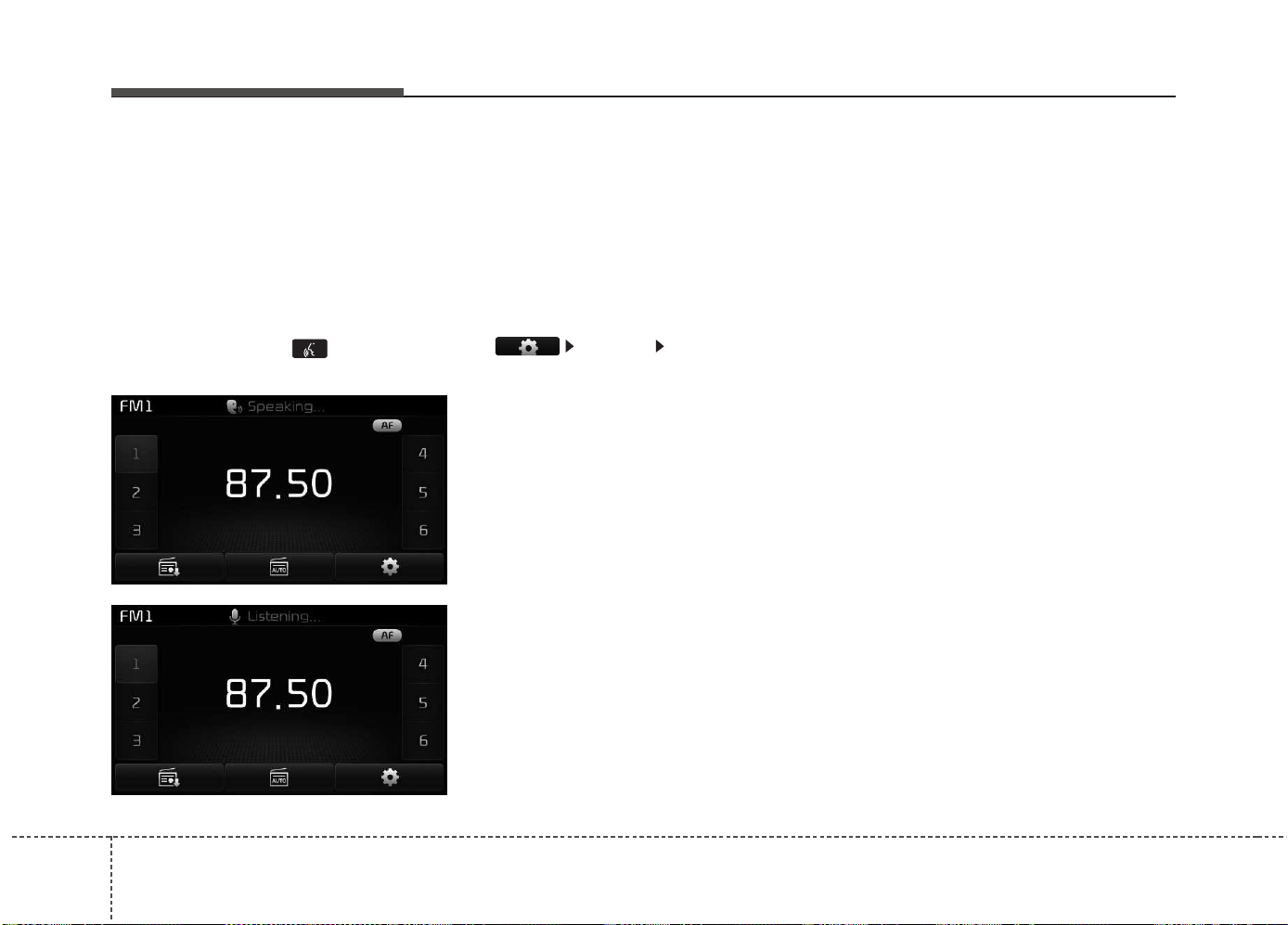
Features of your vehicle
2764
VOICE RECOGNITION
(If equipped)
Using Voice Recognition
Starting Voice Recognition
Shortly press the key on the
steering wheel Say a command.
If voice recognition is in [Normal
Mode], then the system will say
“Please say a command. Beep~”
• If voice recognition is in [Expert
Mode], then the system will only
say a “Beep~”
• To change the Normal
Mode/Expert Mode setting, go to
[System] [Voice Recognition
System].
✽✽
NOTICE
For proper recognition, say the com-
mand after the voice insttction and
beep tone.
Phonebook List Best Practice
1) Do not store single-name entries
(e.g., “Bob”, “Mom”, “Kim”, etc.).
Instead, always use full names
(including first and last names) for
phonebook (e.g., use “Jacob
Stevenson” instead of “Dad”).
2) Do not use abbreviations (i.e., use
“Lieutenant” instead of “Lt.” or
“Sergeant” instead of “Sgt.”).
3) Do not use acronyms (i.e., use
“County Finance Department”
instead of “CFD”).
4) Do not use special characters
(e.g., “@”, “hyphen -”, “asterisk *”,
ampersand &”).
5) If a name is not recognized from
the phonebook, change it to a
more descriptive name (e.g., use
“Grandpa Joseph” instead of “Pa
Joe”).
Features of your vehicle
4 277
Skipping Prompt Messages
While prompt message is being stat-
ed Shortly press the key on the
steering remote controller.
The prompt message is immediately
ended and the beep tone will sound.
After the “beep”, say the voice com-
mand.
Re-starting Voice Recognition
While system waits for a command
Shortly press the key on the
steering remote controller.
The command wait state is immedi-
ately ended and the beep ton will
sound. After the “beep”, say the voice
command.
ENDING VOICE
RECOGNITION
While Voice Recognition is operating
Press and hold the key on the
steering remote controller.
✽✽
NOTICE
• While using voice command,
pressing a steering wheel remote
control or a different key will end
voice command.
• When the system is waiting for a
voice command, say “cancel” or
“end” to end voice command.
• When the system is waiting for a
voice command, press and hold
the key on the steering wheel
to end voice command.
Voice Recognition and
Phonebook Tips:
The Kia Voice Recognition System
may have difficulty understanding
some accents or uncommon names.
When using Voice Recognition to
place a call, speak in a moderate tone,
with clear pronunciation.
To maximize the use of Voice
Recognition, consider these guide-
lines when storing contacts:
• Do not store single-name entries
(e.g., “Bob”, “Mom”, etc.). Instead,
always use full names (including first
and last names) for these contacts.
• Do not use special characters (e.g.,
'@', '-', '*', '&', etc.).
• Do not use abbreviations (i.e., use
"Lieutenant" instead of "Lt.") or
acronyms (i.e., use "County Finance
Department" instead of "C. F. D."; Be
sure to say the name exactly as it is
entered in the contacts list.
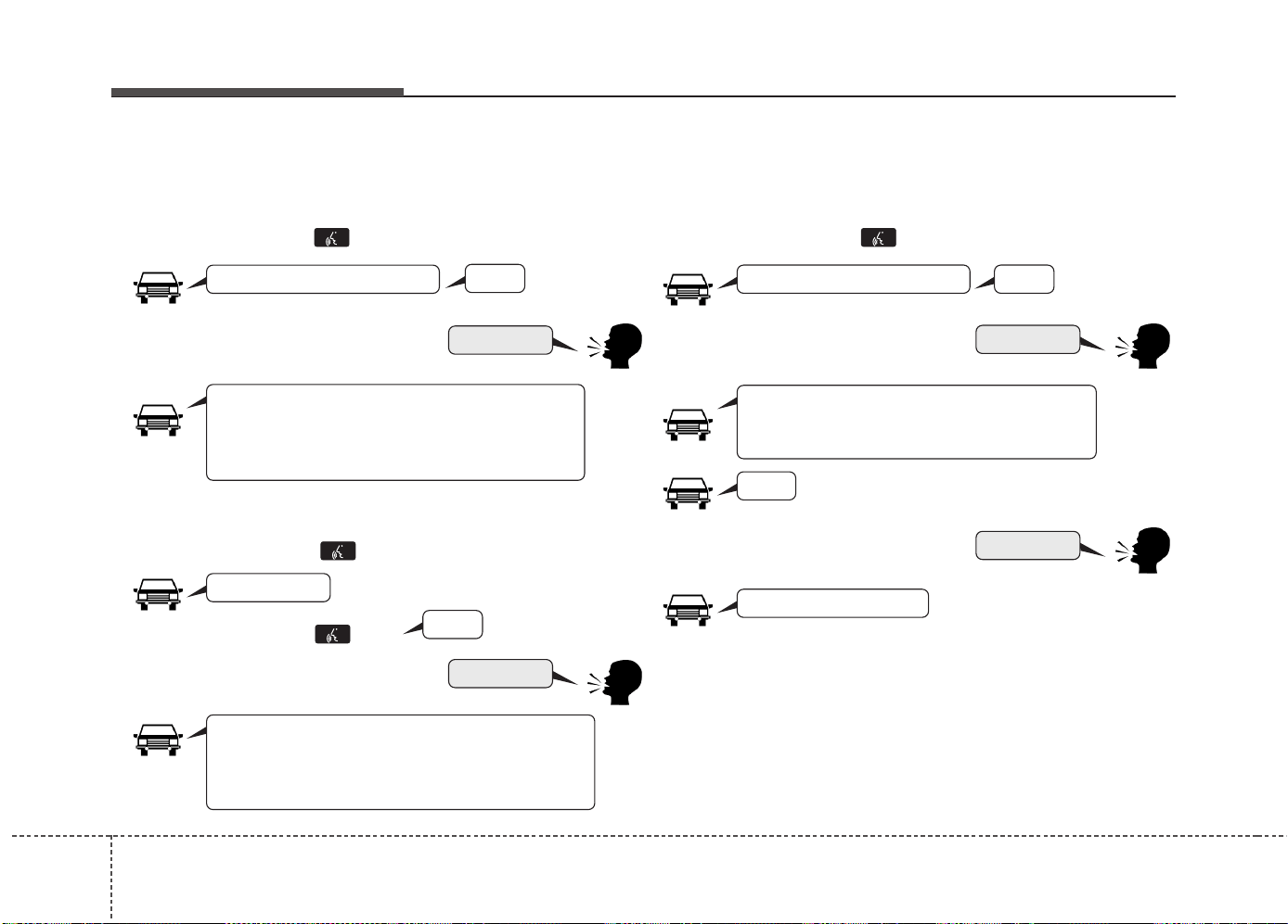
Features of your vehicle
2784
❈ Illustration on using voice commands
• Starting voice command
Shortly pressing the key (under 0.8 seconds):
• Skipping Voice Recognition
Shortly pressing the key (under 0.8 seconds):
• Ending voice command
Shortly pressing the key (under 0.8 seconds):
More Help
More Help
Please say a command
Please say a...
More Help.
You can say Radio, FM, AM, Media, CD, USB, Aux,
My Music, iPod
®
, Bluetooth Audio, Phone, Call
History or Phone book. Please say a command.
More Help.
You can say Radio, FM, AM, Media, CD, USB, Aux,
My Music, iPod
®
, Bluetooth Audio, Phone, Call
History or Phone book. Please say a command.
Ding~
Ding~
Shortly pressing the key
(under 0.8 seconds):
Phone book
Cancel
Please say a command
Phone book.
Please say the name of the phone book you
want to call.
Ding~
Di-Ding~(Cancel Sound)
Ding~
Features of your vehicle
4 279
Voice Command List
• Common Commands: These commands can be used in most operations. (However a few commands may not be
available during certain operations)
Command Function
More Help Provides guidance on commands that can be
used anywhere in the system.
Help Provides guidance on commands that can be
used within the current mode.
Call<Name> Calls <Name> saved in
phone book
Ex) Call “John Smith”
Phone Provides guidance on Phone related com-
mands. After saying this command, say “Call
History”, “
Phone book
”, “Dial Number” to exe-
cute corresponding functions.
Call History Displays the Call History screen.
Phone book
Displays the
phone book
screen. After saying
this command, say the name of a
phone book
saved in the
phone book
to automatically con-
nect the call.
Dial Number Displays the Dial number screen. After saying
this command, you can say the number that
you want to call.
Redial Connects the most recently called number.
Radio
•
When listening to the radio, displays the next
radio screen. (FM1➟ FM2➟ FMA ➟ AM ➟
AMA)
•
When listening to a different mode, displays
the most recently played radio screen.
Command Function
FM
•
When currently listening to the FM radio,
maintains the current state.
•
When listening to a different mode, displays
the most recently played FM screen.
FM1(FM One) Displays the FM1 screen.
FM2(FM Two) Displays the FM2 screen.
FMA Displays the FMA screen.
AM Displays the AM screen.
AMA Displays the AMA screen.
FM Preset 1~6 Plays the most recently played broadcast
saved in FM Preset 1~6.
AM Preset 1~6 Plays the broadcast saved in AM Preset 1~6.
FM 87.5~107.9 Plays the FM broadcast of the corresponding
frequency.
❈ Range can be different by application
frequency of corresponding country.
AM 530~1710 Plays the AM broadcast of the corresponding
frequency.
❈ Range can be different by application
frequency of corresponding country.
TA on Enables Traffic Announcement
TA off Disables Traffic Announcement
News on Enables RDS News feature
News off Disables RDS News feature

Features of your vehicle
2804
Command Function
Media Moves to the most recently played media
screen.
Play Track 1~30 If a music CD has been inserted, plays the
corresponding track.
CD Plays the music saved in the CD.
Search CD Moves to the CD track or file selection screen.
•
For audio CDs, move to the screen and say the
track number to play the corresponding track.
•
Moves to MP3 CD file selection screen. After
manually operate the device to select and
play music.
USB Plays USB music.
Search USB Moves to USB file selection screen. After
manually operate the device to select and play
music.
iPod
®
Plays iPod
®
music.
Search iPod
®
Moves to the iPod
®
file selection screen. After,
manually operate the device to select and play
music.
My Music Plays the music saved in My Music.
Search My Music Moves to My Music file selection screen. After
manually operate the device to select and play
music.
Command Function
AUX (Auxiliary) Plays the connected external device.
Bluetooth Audio Plays the music saved in connected
Bluetooth
®
Wireless Technology
device.
Mute Mutes the radio or music volume.
Pardon? Repeats the most recent comment.
Cancel (Exit) Ends voice command.

Features of your vehicle
4 281
• FM/AM radio Commands: Commands available dur-
ing FM, AM radio operation.
• Audio CD Commands: Commands available during
Audio CD operation.
Command Function
Preset 1~6 Plays the broadcast saved in Preset 1~6.
Auto Store Automatically selects radio broadcast fre-
quencies with superior reception and saves in
Presets 1~6.
Preset Save 1~6 Saves the current broadcast frequency to
Preset 1~6.
Seek up Plays the next (higher) receivable broadcast.
Seek down Plays the previous (lower) receivable broadcast.
Next Preset Selects the preset number next to the most
recently selected preset. (Example: When cur-
rently listening to preset no. 3, then preset no.
4 will be selected.)
Previous Preset Selects the preset number previous to the
most recently selected preset. (Example:
When currently listening to preset no. 3, then
preset no. 2 will be selected.)
Scan Scans receivable frequencies from the current
broadcast and plays for 10 seconds each.
Preset Scan Moves to the next preset from the current
present and plays for 10 seconds each.
AF on Enables Alternative Frequency feature
AF off Disables Alternative Frequency feature
Region Enables Region feature
Region off Disables Region feature
Command Function
Random Randomly plays the tracks within the CD.
Random Off Cancels random play to play tracks in sequen-
tial order.
Repeat Repeats the current track.
Repeat Off Cancels repeat play to play tracks in sequen-
tial order.
Next Track Plays the next track.
Previous Track Plays the previous track.
Scan Scans the tracks from the next track for 10
seconds each.
Track 1~30 Plays the desired track number.
Information Displays the information screen of the current
track.

Features of your vehicle
2824
• MP3 CD / USB Commands: Commands available dur-
ing USB and MP3 CD operation.
• iPod
®
Commands: Commands available during iPod
®
operation.
Command Function
Random Randomly plays the files within the current
folder.
All Random Randomly plays all saved files.
Random Off Cancels random play to play files in sequential
order.
Repeat Repeats the current file.
Folder Repeat Repeats all files in the current folder.
Repeat Off Cancels repeat play to play files in sequential
order.
Next File Plays the next file.
Previous File Plays the previous file.
Scan Scans the files from the next files for 10 sec-
onds each.
Information Displays the information screen of the current
file.
Copy Copies the current file into My Music.
Command Function
All Random Randomly plays all saved songs.
Random Randomly plays the songs within the current
category.
Random Off Cancels random play to play songs in sequen-
tial order.
Repeat Repeats the current song.
Repeat Off Cancels repeat play to play songs in sequen-
tial order.
Next Song Plays the next song.
Previous Song Plays the previous song.
Information Displays the information screen of the current
song.

Features of your vehicle
4 283
• My Music Commands: Commands available during
My Music operation
•
Bluetooth
®
Wireless Technology Audio Commands:
Commands available during
Bluetooth
®
Wireless
Technology audio streaming from mobile phone oper-
ation Command Operation.
Command Function
Random Randomly plays all saved files.
Random Off Cancels random play to play files in sequential
order.
Repeat Repeats the current file.
Repeat Off Cancels repeat play to play files in sequential
order.
Next File Plays the next file.
Previous File Plays the previous file.
Scan Scans the files from the next files for 10 sec-
onds each.
Information Displays the information screen of the current
file.
Delete Deletes the current file. You will bypass an
additional confirmation process.
Delete All Deletes all files saved in My Music. You will
bypass an additional confirmation process.
Command Function
Play Plays the currently paused song.
Pause Pauses the current song.
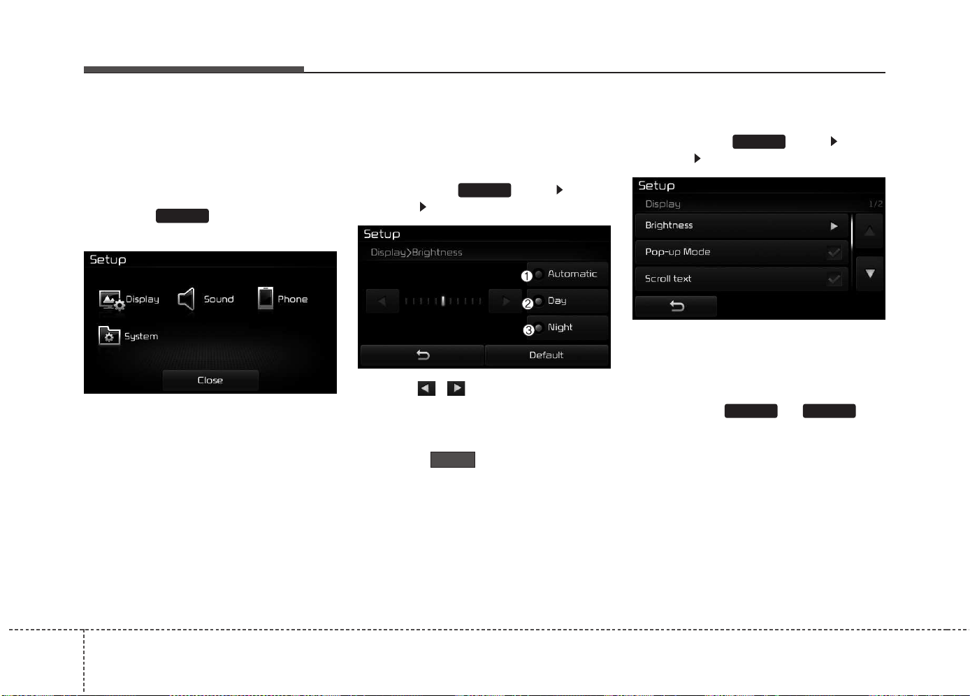
Features of your vehicle
2844
SETUP
Starting Mode
Press the key to display the
Setup screen.
You can select and control options
related to [Display], [Sound],
[Phone] and [System].
Display Settings
Adjusting the Brightness
Press the key Select
[Display] Select [Brightness]
Use the , buttons to adjust the
screen brightness or set the
Brightness on Automatic, Day, or
Night mode.
Press the button to reset.
(1) Automatic : Adjusts the bright-
ness automatically
(2) Day : Always maintains the bright-
ness on high
(3) Night : Always maintains the
brightness on low
Pop-up Mode
Press the key Select
[Display] Select [Pop-up Mode]
This feature is used to display the
Pop-up Mode screen when entering
radio and media modes.
When this feature is turned on,
pressing the or key
will display the Pop-up Mode screen.
✽✽
NOTICE
The media Pop-up Mode screen can
be displayed only when two or more
media modes have been connected.
MEDIA RADIO
SETUP
Default
SETUP
SETUP
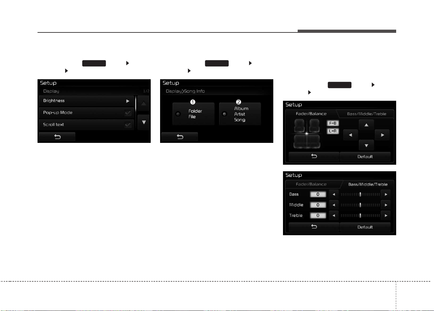
Features of your vehicle
4 285
Scroll Text
Press the key Select
[Display] Select [Scroll text]
This feature is used to scroll text dis-
played on the screen when it is too
long to be displayed at once.
When turned on, the text is repeat-
edly scrolled. When turned off, the
text is scrolled just once.
MP3 Information Display
Press the key Select
[Display] Select [Song Info]
This feature is used to change the
information displayed within USB
and MP3 CD modes.
(1) Folder File : Displays file name
and folder name
(2) Album Artist Song : Displays
album name/artist name/song
Sound Settings
Audio Settings
Press the key Select
[Sound] Select [Audio Settings]
SETUP
SETUPSETUP
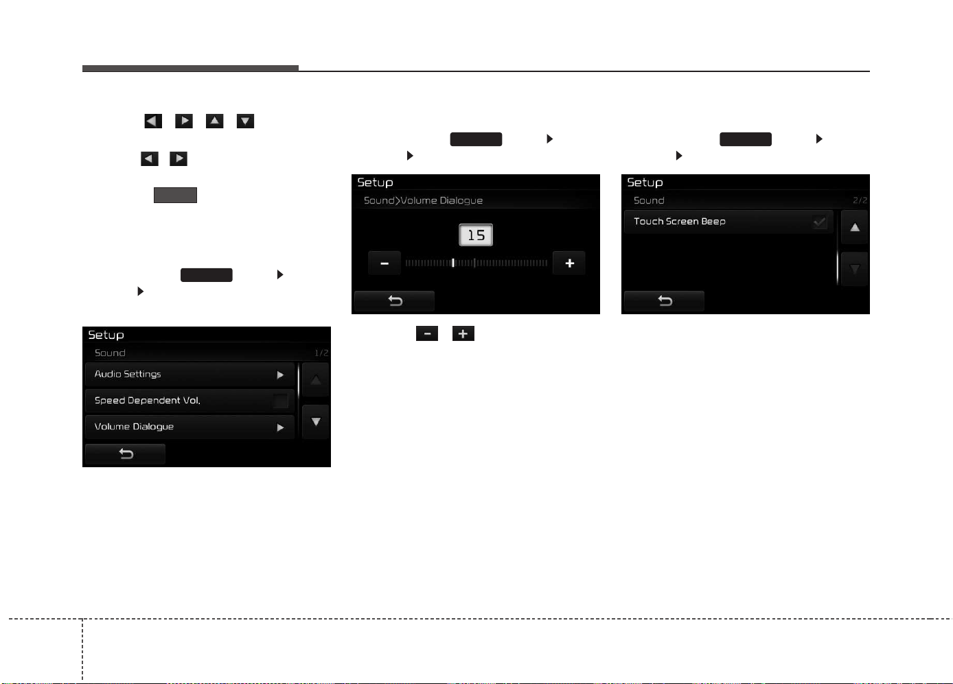
Features of your vehicle
2864
Use the , , , buttons to
adjust the Fader/Balance settings.
Use the , buttons to adjust the
Bass/Middle/Treble settings.
Press the button to reset.
SDVC (Speed Dependent Volume
Control)
Press the key Select
[Sound] Select [Speed Dependent
Vol.]
The volume level is controlled auto-
matically according to the vehicle
speed. SDVC can be set by selecting
from On/Off.
Volume Dialogue
Press the key Select
[Sound] Select [Volume Dialogue]
Use the , buttons to adjust
the Volume Dialog.
Touch Screen Beep
Press the key Select
[Sound] Select [Touch Screen Beep]
This feature is used to turn the touch
screen beep on/off.
SETUPSETUP
SETUP
Default
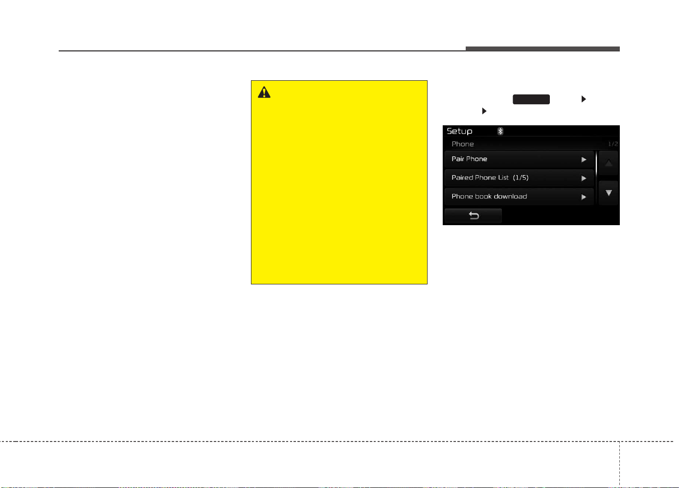
Features of your vehicle
4 287
Bluetooth
®
Wireless Technology
Setting
The Bluetooth
®
word mark and logos
are registered trademarks owned by
Bluetooth SIG, Inc. and any use of
such marks by Kia is under license.
Other trademarks and trade names
are those of their respective owners.
A Bluetooth
®
enabled cell phone is
required to use
Bluetooth
®
Wireless
Technology.
Pairing a New Device
Press the key Select
[Phone] Select [Pair Phone]
Bluetooth
®
Wireless Technology
devices can be paired with the audio
system.
For more information, refer to the
“Pairing through Phone Setup” sec-
tion within
Bluetooth
®
Wireless
Technology.
SETUP
WARNING
Driving while distracted can
result in a loss of vehicle control
that may lead to an accident,
severe personal injury, and
death. The driver’s primary
responsibility is in the safe and
legal operation of a vehicle, and
use of any handheld devices,
other equipment, or vehicle sys-
tems which take the driver’s
eyes, attention and focus away
from the safe operation of a vehi-
cle or which are not permissible
by law should never be used dur-
ing operation of the vehicle.
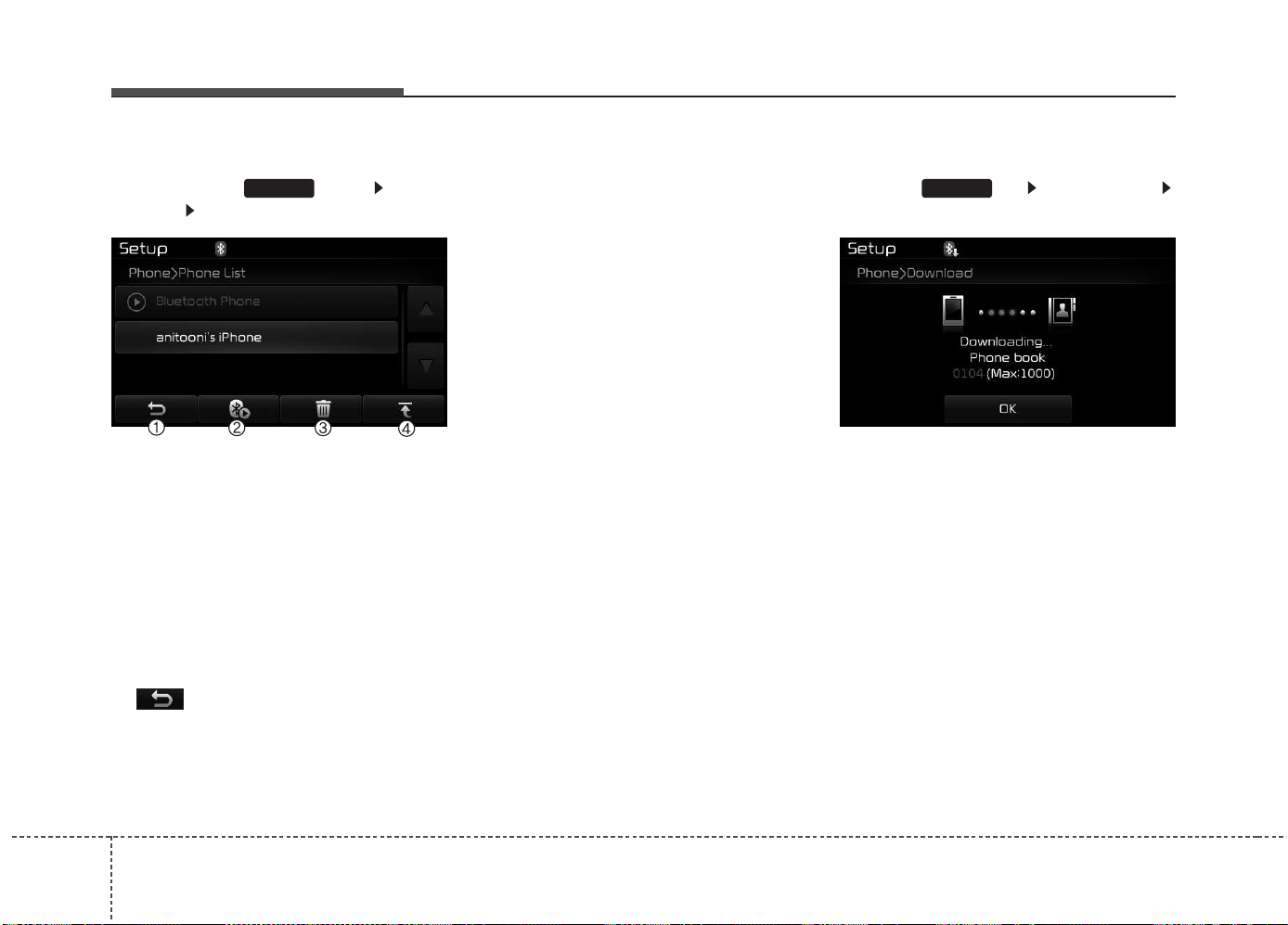
Features of your vehicle
2884
Viewing Paired Phone List
Press the key Select
[Phone] Select [Paired Phone List]
This feature is used to view mobile
phones that have been paired with
the audio system. Upon selecting a
paired phone, the setup menu is dis-
played.
For more information, refer to the
“Setting
Bluetooth
®
Wireless Technology
Connection” section within
Bluetooth
®
Wireless Technology.
1) : Moves to the previous
screen.
2) Connect/Disconnect Phone : Connect/
Disconnects currently selected phone.
3) Delete : Deletes the currently
selected phone
4) Change Priority : Sets currently
selected phone to highest connec-
tion priority
✽✽
NOTICE - BEFORE
DOWNLOADING
PHONE BOOKS
• Only phone books within connect-
ed phones can be downloaded.
Also check to see that your mobile
phone supports the download fea-
ture.
• To learn more about whether your
mobile phone supports phone
book downloads, refer to your
mobile phone user’s manual.
• The Phone book for only the con-
nected phone can be downloaded.
Before downloading, check to see
whether your phone supports the
download feature.
Downloading Phone books
Press the key Select [Phone]
Select [Phone book Download]
The Phone book is downloaded from
the mobile phone and the download
progress is displayed.
✽✽
NOTICE
• Up to 1,000 phone book entries
can be copied into car phone book.
• Up to 1,000 phone book entries
can be saved for each paired
device.
• Upon downloading phone book
data, previously saved phone book
data will be deleted. However,
Phone book entries saved to other
paired phones are not deleted.
SETUPSETUP
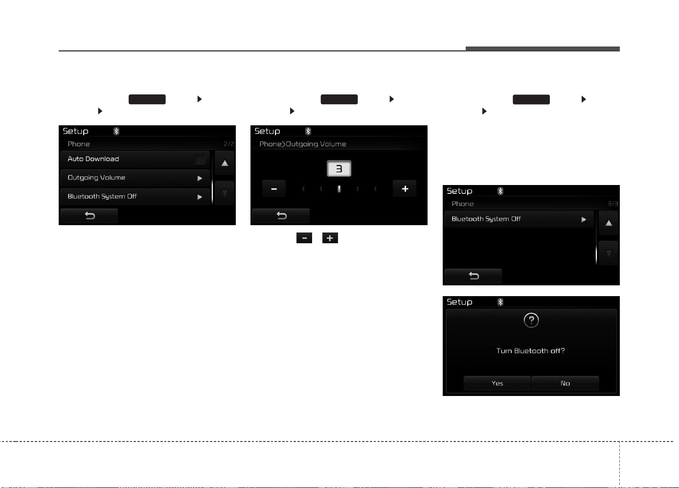
Features of your vehicle
4 289
Auto Download (Phone Book)
Press the key Select
[Phone] Select [Auto Download]
This feature is used to automatically
download mobile phone book entries
once a
Bluetooth
®
Wireless Technology
phone is connected.
✽✽
NOTICE
• The Auto Download feature will
download mobile phone book
entries every time the phone is
connected. The download time
may differ depending on the num-
ber of saved phone book entries
and the communication state.
• When downloading a phone book,
first check to see that your mobile
phone supports the phone book
download feature.
Outgoing Volume
Press the key Select
[Phone] Select [Outgoing Volume]
Use the , buttons to adjust
the outgoing volume level.
Turning Bluetooth System Off
Press the key Select
[Phone] Select [Bluetooth System
Off]
Once
Bluetooth
®
Wireless Technology
is turned off,
Bluetooth
®
Wireless
Technology related features will not
be supported within the audio system.
SETUP
SETUPSETUP
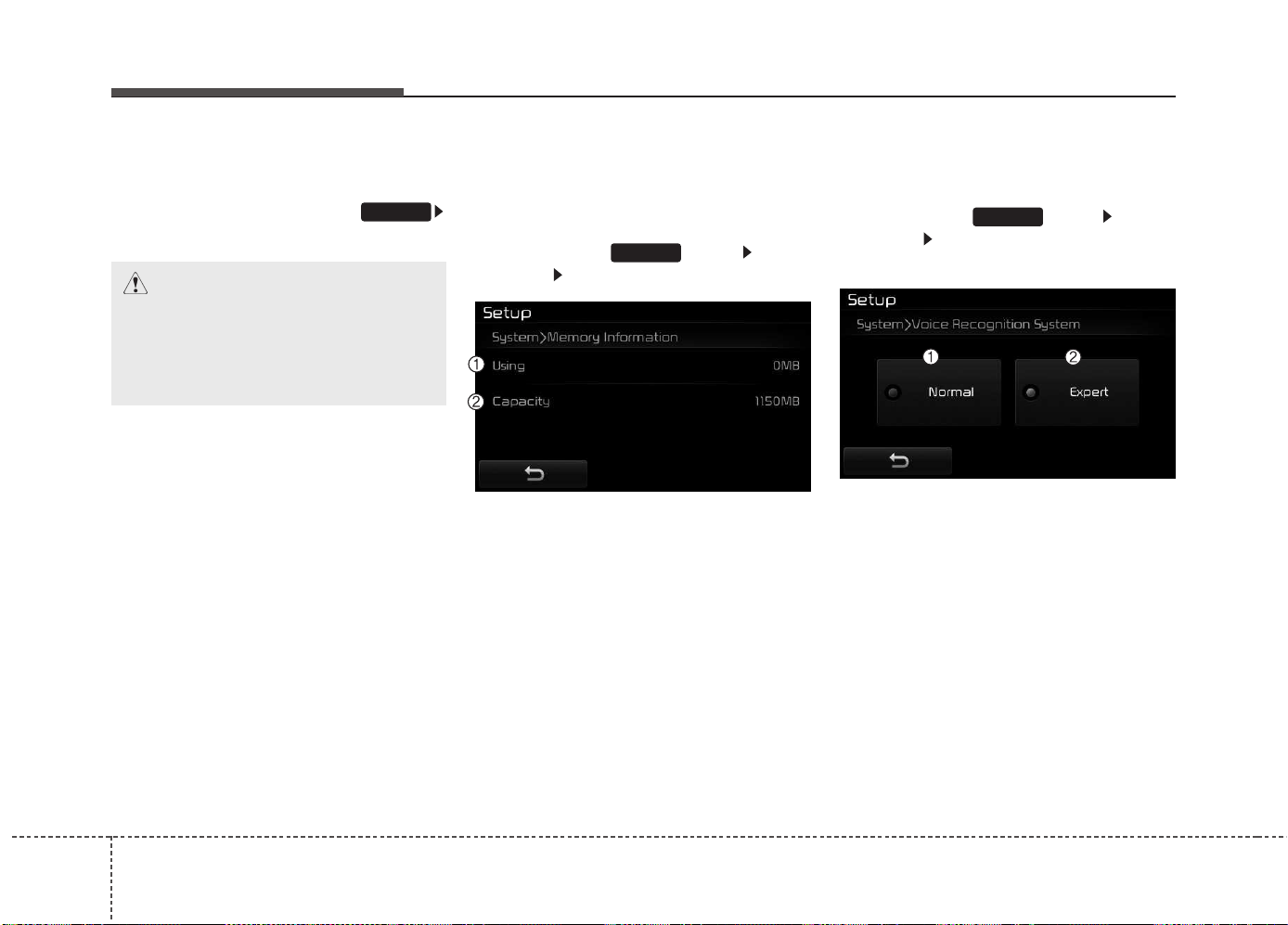
Features of your vehicle
2904
✽✽
NOTICE
To turn Bluetooth
®
Wireless
Technology back on, go to
[Phone] and press “Yes”.
System Setting
Memory Information
Press the key Select
[System] Select [Memory Information]
This feature displays information
related to system memory.
(1) Using : Displays capacity current-
ly in use
(2) Capacity : Displays total capacity
❈ May differ depending on the
selected audio.
Voice Recognition Mode Setting
(If equipped)
Press the key Select
[System] Select [Voice Recognition
System]
This feature is used to select the
desired prompt feedback option from
Normal and Expert.
(1) Normal : When using voice recog-
nition, provides detailed guidance
prompts
(2) Expert : When using voice recog-
nition, omits some guidance
prompts
✽✽
NOTICE
Voice Recognition is depend on the
Audio System.
SETUP
SETUP
SETUP
CAUTION
Bluetooth
®
Wireless Technology
audio streaming may not be sup-
ported in some Bluetooth
®
Wireless Technology phones.
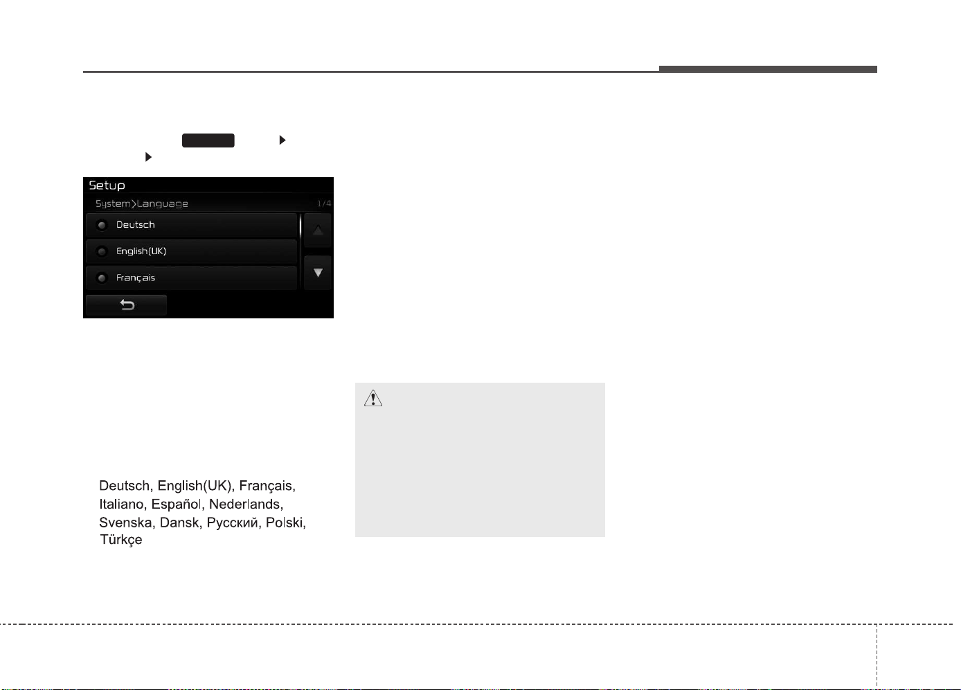
Features of your vehicle
4 291
Language
Press the key Select
[System] Select [Language]
This feature is used to change the
system and voice recognition lan-
guage.
If the language is changed, the sys-
tem will restart and apply the select-
ed language.
❈ Language support by region
REAR VIEW CAMERA
(If equipped)
• The system has been equipped
with a rear view camera for user
safety by allowing a wider rear
range of vision.
• The rear view camera will automat-
ically operate when the ignition key
is turned ON and the transmission
lever is set to R.
• The rear view camera will automat-
ically stop operating when set to a
different lever.
SETUP
CAUTION
The rear view camera has been
equipped with an optical lens to
provide a wider range of vision
and may appear different from
the actual distance. For safety,
directly check the rear and
left/right sides.
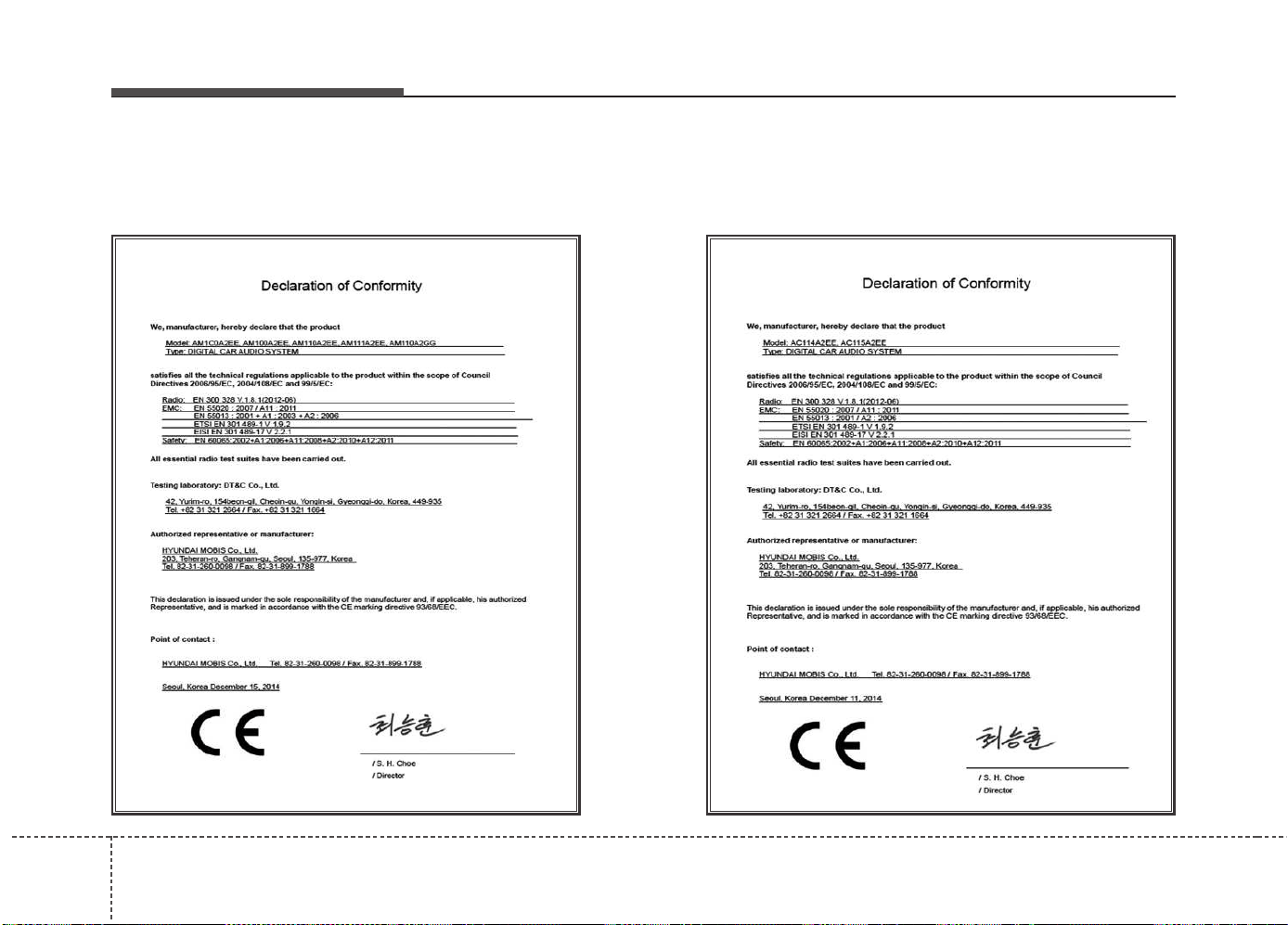
Features of your vehicle
2924
DECLARATION OF CONFORMITY
CE for EU
Features of your vehicle
4 293
RCM for Australia
MOC for Israel
Features of your vehicle
2944

Driving your vehicle
Before driving . . . . . . . . . . . . . . . . . . . . . . . . . . . . . . 5-4
• Before entering vehicle . . . . . . . . . . . . . . . . . . . . . . . . . 5-4
• Necessary inspections . . . . . . . . . . . . . . . . . . . . . . . . . . 5-4
• Before starting . . . . . . . . . . . . . . . . . . . . . . . . . . . . . . . . 5-4
Key positions. . . . . . . . . . . . . . . . . . . . . . . . . . . . . . . 5-5
• Illuminated ignition switch. . . . . . . . . . . . . . . . . . . . . . 5-5
• Ignition switch position. . . . . . . . . . . . . . . . . . . . . . . . . 5-6
• Starting the engine . . . . . . . . . . . . . . . . . . . . . . . . . . . . 5-7
Engine start/stop button . . . . . . . . . . . . . . . . . . . . . 5-9
• Illuminated engine start/stop button . . . . . . . . . . . . . . 5-9
• Engine start/stop button position. . . . . . . . . . . . . . . . . 5-9
• Starting the engine . . . . . . . . . . . . . . . . . . . . . . . . . . . 5-12
ISG (Idle Stop and Go) system . . . . . . . . . . . . . . . 5-15
• Auto stop . . . . . . . . . . . . . . . . . . . . . . . . . . . . . . . . . . . 5-15
• Auto Start. . . . . . . . . . . . . . . . . . . . . . . . . . . . . . . . . . . 5-17
• Condition of ISG system operation . . . . . . . . . . . . . . 5-18
• ISG system deactivation . . . . . . . . . . . . . . . . . . . . . . . 5-18
• ISG system malfunction . . . . . . . . . . . . . . . . . . . . . . . 5-19
Manual Transaxle. . . . . . . . . . . . . . . . . . . . . . . . . . 5-20
• Manual transaxle operation . . . . . . . . . . . . . . . . . . . . 5-20
• Good driving practices . . . . . . . . . . . . . . . . . . . . . . . . 5-22
Automatic transaxle . . . . . . . . . . . . . . . . . . . . . . . . 5-23
• Automatic transaxle operation. . . . . . . . . . . . . . . . . . 5-23
• Good driving practices . . . . . . . . . . . . . . . . . . . . . . . . 5-28
Dual Clutch Transmission (DCT). . . . . . . . . . . . . 5-30
• Dual clutch transmission operation. . . . . . . . . . . . . . 5-30
• Good driving practices . . . . . . . . . . . . . . . . . . . . . . . . 5-37
Active ECO system . . . . . . . . . . . . . . . . . . . . . . . . . 5-39
• Active ECO operation. . . . . . . . . . . . . . . . . . . . . . . . . 5-39
• When Active ECO is activated. . . . . . . . . . . . . . . . . . 5-39
• Limitation of Active ECO operation . . . . . . . . . . . . . 5-39
Brake system. . . . . . . . . . . . . . . . . . . . . . . . . . . . . . 5-40
• Power brakes . . . . . . . . . . . . . . . . . . . . . . . . . . . . . . . . 5-40
• Parking brake - Hand type. . . . . . . . . . . . . . . . . . . . . 5-42
• Electric parking brake (EPB) . . . . . . . . . . . . . . . . . . 5-44
• Anti-lock brake system (ABS) . . . . . . . . . . . . . . . . . . 5-48
• Electronic stability control (ESC) . . . . . . . . . . . . . . . 5-51
• Vehicle stability management (VSM) . . . . . . . . . . . . 5-54
• Hill-start assist control (HAC) . . . . . . . . . . . . . . . . . . 5-55
• Emergency Stop Signal (ESS) . . . . . . . . . . . . . . . . . . 5-56
• Good braking practices. . . . . . . . . . . . . . . . . . . . . . . . 5-56
Cruise Control system . . . . . . . . . . . . . . . . . . . . . . 5-58
Speed limit control system. . . . . . . . . . . . . . . . . . . 5-63
Lane departure warning system (LDWS) . . . . . . 5-66
Speed Limit Information Function (SLIF) . . . . . 5-69
• SLIF activation / deactivation . . . . . . . . . . . . . . . . . . 5-69
• Operation . . . . . . . . . . . . . . . . . . . . . . . . . . . . . . . . . . . 5-70
• Display . . . . . . . . . . . . . . . . . . . . . . . . . . . . . . . . . . . . . 5-70
• Warning message. . . . . . . . . . . . . . . . . . . . . . . . . . . . . 5-72
5

• Driver's attention. . . . . . . . . . . . . . . . . . . . . . . . . . . . . 5-73
Blind Spot Detection system (BSD) . . . . . . . . . . . 5-74
• BSD (Blind Spot Detection) /
LCA (Lane Change Assist). . . . . . . . . . . . . . . . . . . . 5-74
• RCTA (Rear cross traffic alert) . . . . . . . . . . . . . . . . . 5-78
• Driver’s Attention . . . . . . . . . . . . . . . . . . . . . . . . . . . . 5-80
Economical operation . . . . . . . . . . . . . . . . . . . . . . 5-81
Special driving conditions . . . . . . . . . . . . . . . . . . . 5-83
• Hazardous driving conditions . . . . . . . . . . . . . . . . . . 5-83
• Rocking the vehicle . . . . . . . . . . . . . . . . . . . . . . . . . . . 5-83
• Smooth cornering . . . . . . . . . . . . . . . . . . . . . . . . . . . . 5-84
• Driving at night . . . . . . . . . . . . . . . . . . . . . . . . . . . . . . 5-84
• Driving in the rain. . . . . . . . . . . . . . . . . . . . . . . . . . . . 5-84
• Driving in flooded areas . . . . . . . . . . . . . . . . . . . . . . . 5-85
• Driving off-road. . . . . . . . . . . . . . . . . . . . . . . . . . . . . . 5-85
• Highway driving . . . . . . . . . . . . . . . . . . . . . . . . . . . . . 5-85
Winter driving . . . . . . . . . . . . . . . . . . . . . . . . . . . . 5-86
• Snowy or Icy conditions . . . . . . . . . . . . . . . . . . . . . . . 5-86
• Use high quality ethylene glycol coolant . . . . . . . . . . 5-88
• Check battery and cables . . . . . . . . . . . . . . . . . . . . . . 5-88
• Change to "winter weight" oil if necessary . . . . . . . 5-88
• Check spark plugs and ignition system. . . . . . . . . . . 5-88
• To keep locks from freezing . . . . . . . . . . . . . . . . . . . . 5-89
• Use approved window washer
anti-freeze in system . . . . . . . . . . . . . . . . . . . . . . . . . 5-89
• Don't let your parking brake freeze . . . . . . . . . . . . . 5-89
• Don't let ice and snow accumulate underneath . . . . 5-89
• Carry emergency equipment . . . . . . . . . . . . . . . . . . . 5-89
Trailer Towing . . . . . . . . . . . . . . . . . . . . . . . . . . . . 5-90
• Hitches . . . . . . . . . . . . . . . . . . . . . . . . . . . . . . . . . . . . . 5-91
• Safety chains . . . . . . . . . . . . . . . . . . . . . . . . . . . . . . . . 5-92
• Trailer brakes . . . . . . . . . . . . . . . . . . . . . . . . . . . . . . . 5-92
• Driving with a trailer . . . . . . . . . . . . . . . . . . . . . . . . . 5-92
• Maintenance when trailer towing . . . . . . . . . . . . . . . 5-96
• If you do decide to pull a trailer . . . . . . . . . . . . . . . . 5-97
Vehicle weight . . . . . . . . . . . . . . . . . . . . . . . . . . . . 5-100
• Base curb weight . . . . . . . . . . . . . . . . . . . . . . . . . . . . 5-100
• Vehicle curb weight . . . . . . . . . . . . . . . . . . . . . . . . . . 5-100
• Cargo weight . . . . . . . . . . . . . . . . . . . . . . . . . . . . . . . 5-100
• GAW (Gross axle weight) . . . . . . . . . . . . . . . . . . . . . 5-100
• GAWR (Gross axle weight rating) . . . . . . . . . . . . . . 5-100
• GVW (Gross vehicle weight) . . . . . . . . . . . . . . . . . . 5-100
• GVWR (Gross vehicle weight rating) . . . . . . . . . . . 5-100
• Overloading . . . . . . . . . . . . . . . . . . . . . . . . . . . . . . . . 5-100
5

53
Driving your vehicle
WARNING - ENGINE EXHAUST CAN BE DANGEROUS!
Engine exhaust fumes can be extremely dangerous. If, at any time, you smell exhaust fumes inside the vehicle, open the win-
dows immediately.
• Do not inhale exhaust fumes.
Exhaust fumes contain carbon monoxide, a colorless, odorless gas that can cause unconsciousness and death by asphyxia-
tion.
• Be sure the exhaust system does not leak.
The exhaust system should be checked whenever the vehicle is raised to change the oil or for any other purpose. If you hear
a change in the sound of the exhaust or if you drive over something that strikes the underneath side of the vehicle, we rec-
ommend that the system be checked by an authorized Kia dealer.
• Do not run the engine in an enclosed area.
Letting the engine idle in your garage, even with the garage door open, is a hazardous practice. Never run the engine in your
garage any longer than it takes to start the engine and back the vehicle out.
• Avoid idling the engine for prolonged periods with people inside the vehicle.
If it is necessary to idle the engine for a prolonged period with people inside the vehicle, be sure to do so only in an open area
with the air intake set at "Fresh" and fan operating at one of the higher speeds so fresh air is drawn into the interior.
If you must drive with the tailgate/trunk open because you are carrying objects that make this necessary:
1. Close all windows.
2. Open side vents.
3. Set the air intake control at "Fresh", the air flow control at "Floor" or "Face" and the fan at one of the higher speeds.
To assure proper operation of the ventilation system, be sure the ventilation air intakes located just in front of the windshield are
kept clear of snow, ice, leaves or other obstructions.
Driving your vehicle
45
Before entering vehicle
• Be sure that all windows, outside mir-
ror(s), and outside lights are clean.
• Check the condition of the tires.
• Check under the vehicle for any sign of
leaks.
• Be sure there are no obstacles behind
you if you intend to back up.
Necessary inspections
Fluid levels, such as engine oil, engine
coolant, brake fluid, and washer fluid
should be checked on a regular basis,
with the exact interval depending on the
fluid. Further details are provided in
chapter 7, “Maintenance”.
Before starting
• Close and lock all doors.
• Position the seat so that all controls are
easily reached.
• Adjust the inside and outside rearview
mirrors.
• Be sure that all lights work.
• Check all gauges.
• Check the operation of warning lights
when the ignition switch is turned to
the ON position.
• Release the parking brake and make
sure the brake warning light goes out.
For safe operation, be sure you are famil-
iar with your vehicle and its equipment.
BEFORE DRIVING
WARNING
All passengers must be properly
belted whenever the vehicle is mov-
ing. Refer to “Seat belts” in chapter
3 for more information on their
proper use.
WARNING
Always check the surrounding areas
near your vehicle for people, espe-
cially children, before putting a vehi-
cle into “D (Drive)” or “R (Reverse)”.
WARNING
Driving while distracted can result
in a loss of vehicle control, that
may lead to an accident, severe
personal injury, and death. The dri-
ver’s primary responsibility is in
the safe and legal operation of a
vehicle, and use of any handheld
devices, other equipment, or vehi-
cle systems which take the driver’s
eyes, attention and focus away
from the safe operation of a vehicle
or which are not permissible by law
should never be used during oper-
ation of the vehicle.
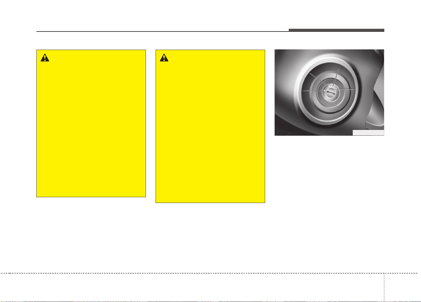
55
Driving your vehicle
Illuminated ignition switch
Whenever a front door is opened, the
ignition switch will be illuminated for your
convenience, provided the ignition switch
is not in the ON position. The light will go
off immediately when the ignition switch
is turned on or go off after about 30 sec-
onds when the door is closed.
KEY POSITIONS
WARNING - Driving under
the influence of alcohol or
drugs
Drinking and driving is dangerous.
Drunk driving is the number one
contributor to the highway death
toll each year. Even a small amount
of alcohol will affect your reflexes,
perceptions and judgement.
Driving while under the influence of
drugs is as dangerous or more dan-
gerous than driving drunk.
You are much more likely to have a
serious accident if you drink or
take drugs and drive.
If you are drinking or taking drugs,
don’t drive. Do not ride with a driv-
er who has been drinking or taking
drugs. Choose a designated driver
or call a cab.
WARNING
• When you intend to park or stop
the vehicle with the engine on, be
careful not to depress the accel-
erator pedal for a long period of
time. It may overheat the engine
or exhaust system and cause fire.
• When you make a sudden stop or
turn the steering wheel rapidly,
loose objects may drop on the
floor and it could interfere with
the operation of the foot pedals,
possibly causing an accident.
Keep all things in the vehicle
safely stored.
• If you do not focus on driving, it
may cause an accident. Be care-
ful when operating what may dis-
turb driving such as audio or
heater. It is the responsibility of
the driver to always drive safely.
OGDE051055
ACC
ON
START
LOCK
Driving your vehicle
65
Ignition switch position
LOCK
The steering wheel locks to protect
against theft. The ignition key can be
removed only in the LOCK position.
When turning the ignition switch to the
LOCK position, push the key inward at
the ACC position and turn the key toward
the LOCK position.
ACC (Accessory)
The steering wheel is unlocked and elec-
trical accessories are operative.
✽✽
NOTICE
If difficulty is experienced turning the
ignition switch to the ACC position, turn
the key while turning the steering wheel
right and left to release the tension.
ON
The warning lights can be checked
before the engine is started. This is the
normal running position after the engine
is started.
Do not leave the ignition switch ON if the
engine is not running to prevent battery
discharge.
START
Turn the ignition key to the START posi-
tion to start the engine. The engine will
crank until you release the key; then it
returns to the ON position. The brake
warning lamp can be checked in this
position.
WARNING - Ignition key
• Never turn the ignition switch to
LOCK or ACC while the vehicle is
moving. This would result in loss of
directional control and braking func-
tion, which could cause an accident.
• The anti-theft steering column lock
(if equipped) is not a substitute for
the parking brake. Before leaving
the driver’s seat, always make sure
the shift lever is engaged in 1
st
gear
for the manual transaxle or P (Park)
for the automatic transaxle, set the
parking brake fully and shut the
engine off. Unexpected and sud-
den vehicle movement may occur if
these precautions are not taken.
• Never reach for the ignition switch,
or any other controls through the
steering wheel while the vehicle is in
motion. The presence of your hand
or arm in this area could cause a
loss of vehicle control, an accident
and serious bodily injury or death.
• Do not place any movable objects
around the driver’s seat as they
may move while driving, interfere
with the driver and lead to an acci-
dent.
57
Driving your vehicle
Starting the engine
✽✽
NOTICE - Kick down mecha-
nism
If your vehicle is equipped with a kick
down mechanism in the accelerator
pedal, it prevents you from driving at
full throttle unintentionally by making
the driver require increased effort to
depress the accelerator pedal. However,
if you depress the pedal more than
approximately 80%, the vehicle can be
at full throttle and the accelerator pedal
will be easier to depress. This is not a
malfunction but a normal condition.
Starting the gasoline engine
1.Make sure the parking brake is
applied.
2.Manual Transaxle - Depress the
clutch pedal fully and shift the
transaxle into Neutral. Keep the clutch
pedal and brake pedal depressed
while turning the ignition switch to the
start position.
Automatic Transaxle/DCT* - Place
the transaxle shift lever in P (Park).
Depress the brake pedal fully.
You can also start the engine when the
shift lever is in the N (Neutral) position.
* DCT : Dual clutch transmission
3.Turn the ignition switch to START and
hold it there until the engine starts (a
maximum of 10 seconds), then release
the key.
It should be started without depressing
the accelerator pedal.
4.Do not wait for the engine to warm up
while the vehicle remains stationary.
Start driving at moderate engine
speeds. (Steep accelerating and decel-
erating should be avoided.)
CAUTION
If the engine stalls while you are in
motion, do not attempt to move the
shift lever to the P (Park) position. If
traffic and road conditions permit,
you may put the shift lever in the N
(Neutral) position while the vehicle
is still moving and turn the ignition
switch to the START position in an
attempt to restart the engine.
CAUTION
Do not engage the starter for more
than 10 seconds. If the engine stalls
or fails to start, wait 5 to 10 seconds
before re-engaging the starter.
Improper use of the starter may dam-
age it.
WARNING
Always wear appropriate shoes
when operating your vehicle.
Unsuitable shoes (high heels, ski
boots,etc.) may interfere with your
ability to use the brake and acceler-
ator pedal, and clutch (if equipped).
Driving your vehicle
85
Starting the diesel engine
To start the diesel engine when the
engine is cold, it has to be pre-heated
before starting the engine and then have
to be warmed up before starting to drive.
1.Make sure the parking brake is
applied.
2.Manual Transaxle - Depress the
clutch pedal fully and shift the
transaxle into Neutral. Keep the clutch
pedal and brake pedal depressed
while turning the ignition switch to the
start position.
Automatic Transaxle / DCT* - Place
the transaxle shift lever in P(park).
Depress the brake pedal fully.
You can also start the engine when the
shift lever is in the N(neutral) position.
* DCT : Dual clutch transmission
3. Turn the ignition switch to the ON posi-
tion to pre-heat the engine. Then the
glow indicator light will illuminate.
4. If the glow indicator light goes out, turn
the ignition switch to the START posi-
tion and hold it there until the engine
starts (a maximum of 10 seconds),
then release the key.
✽✽
NOTICE
If the engine does not start within 10
seconds after the preheating is complet-
ed, turn the ignition key once more to
the LOCK position for 10 seconds, and
then to the ON position, in order to pre-
heat again.
Starting and stopping the engine for tur-
bocharger intercooler
1. Do not race or accelerate the engine
immediately after starting.
If the engine is cold, idle for several
seconds before sufficient lubrication is
ensured in the turbocharger unit.
2. After high speed or extended driving,
requiring a heavy engine load, run the
engine on idle condition about 1
minute before turning it off.
This idle time will allow the tur-
bocharger to cool prior to shutting the
engine off.
W-60
Glow indicator light
CAUTION
Do not turn off the engine immedi-
ately after it has been subjected to
a heavy load. Doing so may cause
severe damage to the engine or
turbo charger unit.
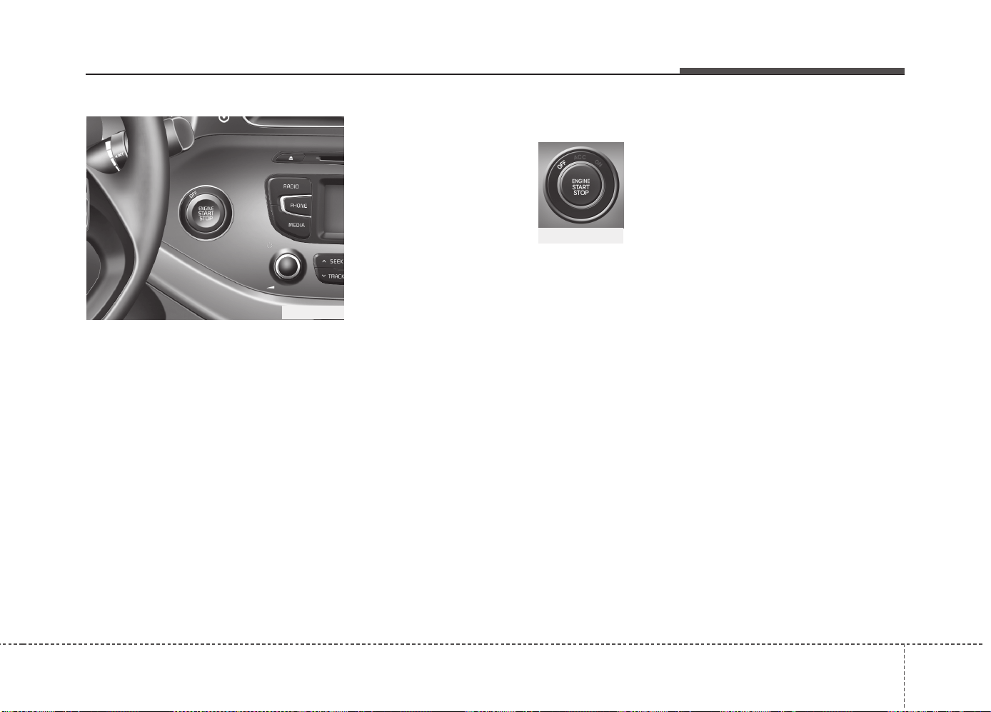
59
Driving your vehicle
ENGINE START/STOP BUTTON (IF EQUIPPED)
Illuminated engine start/stop but-
ton
Whenever the front door is opened, the
engine start/stop button will illuminate for
your convenience. The light will go off
after about 30 seconds when the door is
closed. It will also go off immediately
when the theft-alarm system is armed.
Engine start/stop button position
OFF
With manual transaxle
To turn off the engine (START/RUN posi-
tion) or vehicle power (ON position), stop
the vehicle then press the engine
start/stop button.
With automatic transaxle/DCT*
To turn off the engine (START/RUN posi-
tion) or vehicle power (ON position),
press the engine start/stop button with
the shift lever in the P (Park) position.
When you press the engine start/stop
button without the shift lever in the P
(Park) position, the engine start/stop but-
ton will not change to the OFF position
but to the ACC position.
* DCT : Dual clutch transmission
Vehicles equipped with anti-theft steering
column lock
The steering wheel locks when the
engine start/stop button is in the OFF
position to protect you against theft.
It locks when the door is opened.
If the steering wheel is not locked prop-
erly when you open the driver's door, the
warning chime will sound. Try locking the
steering wheel again. If the problem is
not solved, we recommend that the sys-
tem be checked by an authorized Kia
dealer.
In addition, if the engine start/stop button
is in the OFF position after the driver's
door is opened, the steering wheel will
not lock and the warning chime will
sound. In such a situation, close the door.
Then the steering wheel will lock and the
warning chime will stop.
✽✽
NOTICE
If the steering wheel doesn't unlock
properly, the engine start/stop button
will not work. Press the engine
start/stop button while turning the
steering wheel right and left to release
the tension.
OJD052001
White
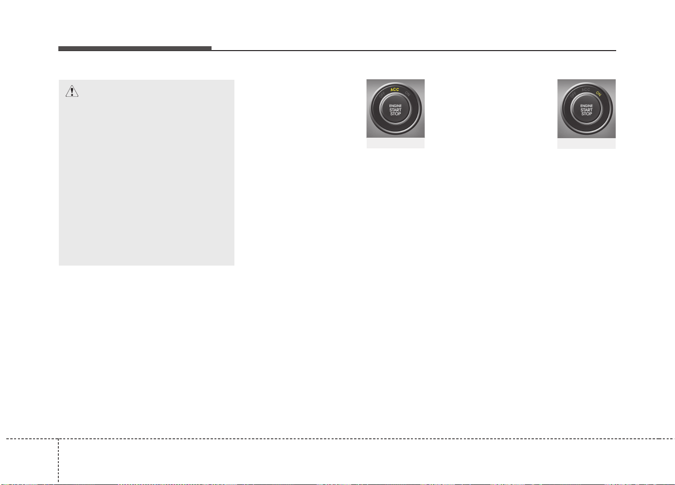
Driving your vehicle
105
ACC(Accessory)
With manual transaxle
Press the engine start/stop button when
the button is in the OFF position without
depressing the clutch pedal.
With automatic transaxle/DCT
Press the engine start/stop button while it
is in the OFF position without depressing
the brake pedal.
The steering wheel unlocks (if equipped
with anti-theft steering column lock) and
electrical accessories are operational.
If the engine start/stop button is in the
ACC position for more than 1 hour, the
button is turned off automatically to pre-
vent battery discharge.
ON
With manual transaxle
Press the engine start/stop button when
the button is in the ACC position without
depressing the clutch pedal.
With automatic transaxle/DCT
Press the engine start/stop button while it
is in the ACC position without depressing
the brake pedal.
The warning lights can be checked
before the engine is started. Do not leave
the engine start/stop button in the ON
position for a long time. The battery may
discharge, because the engine is not
running.
CAUTION
You are able to turn off the engine
(START/RUN) or vehicle power (ON),
only when the vehicle is not in
motion. In an emergency situation
while the vehicle is in motion, you are
able to turn the engine off and to the
ACC position by pressing the engine
start/stop button for more than 2 sec-
onds or 3 times successively within 3
seconds. If the vehicle is still moving,
you can restart the engine without
depressing the brake pedal by press-
ing the engine start/stop button with
the shift lever in the N (Neutral) posi-
tion.
Orange
Red
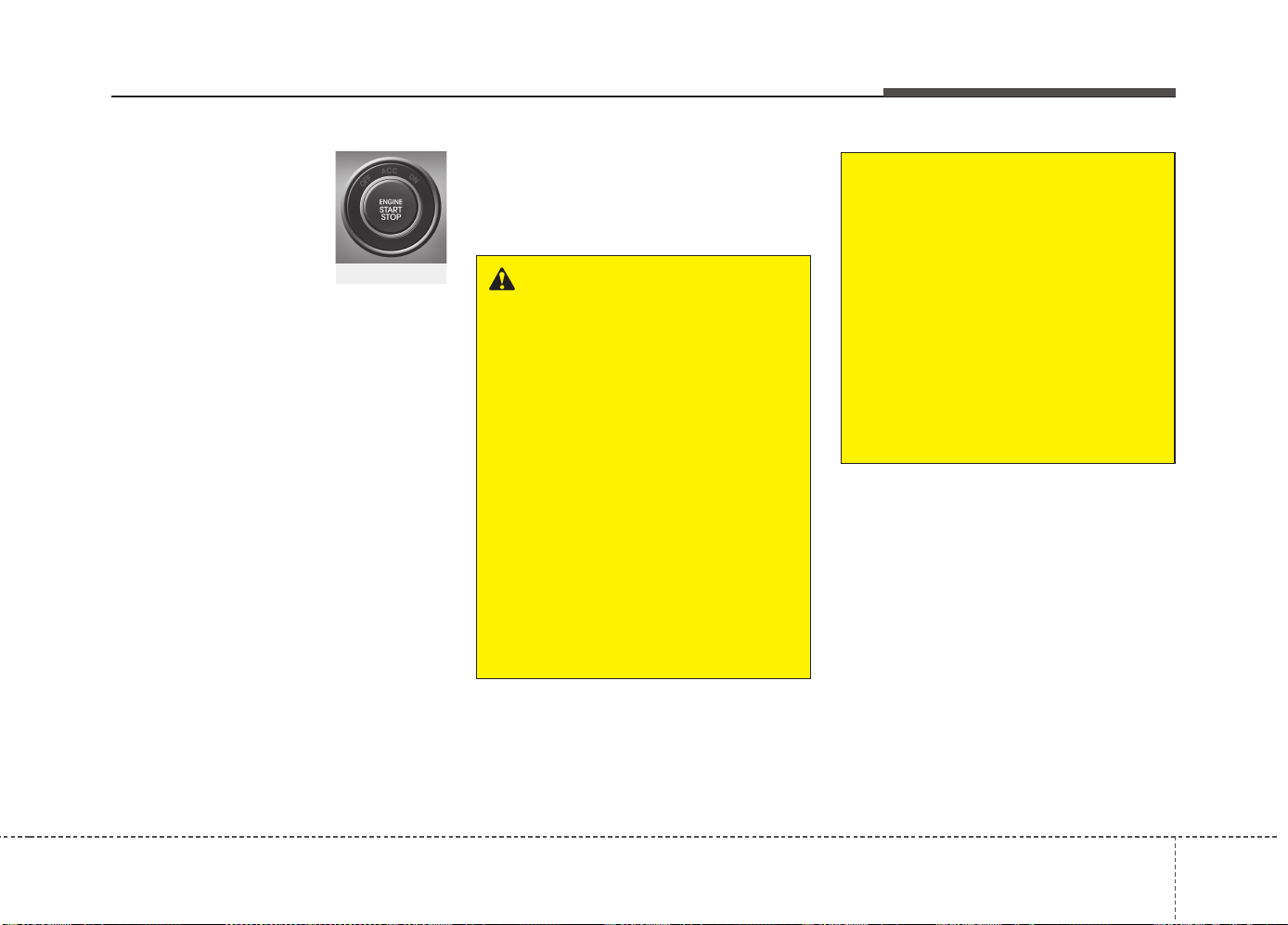
511
Driving your vehicle
START/RUN
With manual transaxle
To start the engine, depress the clutch
pedal and brake pedal, then press the
engine start/stop button with the shift
lever in the N (Neutral) position.
With automatic transaxle/DCT
To start the engine, depress the brake
pedal and press the engine start/stop
button with the shift lever in the P (Park)
or the N (Neutral) position. For your safe-
ty, start the engine with the shift lever in
the P (Park) position.
✽✽
NOTICE
If you press the engine start/stop button
without depressing the clutch pedal for
manual transaxle vehicles or without
depressing the brake pedal for automat-
ic transaxle vehicles, the engine will not
start and the engine start/stop button
changes as follow:
OFF
➔
➔
ACC
➔➔
ON
➔➔
OFF or ACC
✽
✽
NOTICE
If you leave the engine start/stop button
in the ACC or ON position for a long
time, the battery will discharge.
WARNING
• Never press the engine start/stop
button while the vehicle is in
motion. This would result in loss
of directional control and braking
function, which could cause an
accident.
• The anti-theft steering column
lock (if equipped) is not a substi-
tute for the parking brake. Before
leaving the driver's seat, always
make sure the shift lever is
engaged in P (Park), set the park-
ing brake fully and shut the
engine off. Unexpected and sud-
den vehicle movement may occur
if these precautions are not
taken.
(Continued)
(Continued)
• Never reach for the engine start/
stop button or any other controls
through the steering wheel while
the vehicle is in motion.The pres-
ence of your hand or arm in the
area could cause loss of vehicle
control, an accident and serious
bodily injury or death.
• Do not place any movable objects
around the driver's seat as they
may move while driving, interfere
with the driver and lead to an
accident.
Not illuminated

Driving your vehicle
125
Starting the engine
✽✽
NOTICE - Kick down mecha-
nism (if equipped)
If your vehicle is equipped with a kick
down mechanism in the accelerator
pedal, it prevents you from driving at
full throttle unintentionally by making
the driver require increased effort to
depress the accelerator pedal. However,
if you depress the pedal more than
approximately 80%, the vehicle can be
at full throttle and the accelerator pedal
will be easier to depress. This is not a
malfunction but a normal condition.
Starting the gasoline engine
1.Carry the smart key or leave it inside
the vehicle.
2.Make sure the parking brake is firmly
applied.
3.Manual Transaxle - Depress the
clutch pedal fully and shift the
transaxle into Neutral. Keep the clutch
pedal and brake pedal depressed
while starting the engine.
Automatic transaxle/DCT* - Place the
transaxle shift lever in P (Park).
Depress the brake pedal fully.
You can also start the engine when the
shift lever is in the N (Neutral) position.
* DCT : Dual clutch transmission
4.Press the engine start/stop button.
It should be started without depressing
the accelerator.
5.Do not wait for the engine to warm up
while the vehicle remains stationary.
Start driving at moderate engine
speeds. (Steep accelerating and decel-
erating should be avoided.)
Starting the diesel engine
To start the diesel engine when the
engine is cold, it has to be pre-heated
before starting the engine and then have
to be warmed up before starting to drive.
1.Make sure the parking brake is
applied.
2.Manual Transaxle - Depress the
clutch pedal fully and shift the
transaxle into Neutral. Keep the clutch
pedal and brake pedal depressed
while pressing the engine start/stop
button to the START position.
Automatic Transaxle / DCT* - Place
the transaxle shift lever in P (Park).
Depress the brake pedal fully.
You can also start the engine when the
shift lever is in the N (Neutral) position.
WARNING
• Always wear appropriate shoes
when operating your vehicle.
Unsuitable shoes (high heels, ski
boots,etc.) may interfere with
your ability to use the brake and
accelerator pedal.
• Do not start the vehicle with the
accelerator pedal depressed. The
vehicle can move and lead to an
accident.
• Wait until the engine rpm is normal.
The vehicle may suddenly move if
the brake padel is released when
the rpm is high.
513
Driving your vehicle
3. Press the engine start/stop button
while depressing the brake pedal.
4. Continue depressing the brake pedal
until the illuminated glow indicator
goes off. (approximately 5 seconds)
5. The engine starts running when the
glow indicator goes off.
✽✽
NOTICE
If the engine start/stop button is pressed
once more while the engine is pre-heat-
ing, the engine may start.
Starting and stopping the engine for tur-
bocharger intercooler
1. Do not race or accelerate the engine
immediately after starting.
If the engine is cold, idle for several
seconds before sufficient lubrication is
ensured in the turbocharger unit.
2. After high speed or extended driving,
requiring a heavy engine load, idle the
engine about 1 minute before turning it
off.
This idle time will allow the tur-
bocharger to cool prior to shutting the
engine off.
• Even if the smart key is in the vehicle,
if it is far away from you, the engine
may not start.
• When the engine start/stop button is in
the ACC position or above, if any door is
opened, the system checks for the
smart key. If the smart key is not in the
vehicle, a message “Key not in vehicle”
will appear on the LCD display. And if all
doors are closed, the chime will sound
for 5 seconds. The indicator or warning
will turn off while the vehicle is moving.
Always have the smart key with you.
WARNING
The engine will start, only when the
smart key is in the vehicle.
Never allow children or any person
who is unfamiliar with the vehicle
touch the engine start/stop button
or related parts.
CAUTION
Do not turn the engine off immedi-
ately after it has been subjected to
a heavy load. Doing so may cause
severe damage to the engine or tur-
bocharger unit.
W-60
Glow indicator light
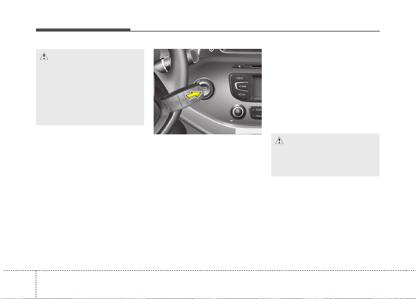
Driving your vehicle
145
✽✽
NOTICE
• If the battery is weak or the smart key
does not work correctly, you can start
the engine by pressing the engine
start/stop button with the smart key.
The side with the lock button should
be contacted directly.
If you press the smart key directly to
the engine start/stop button, the engine
start/stop button and the smart key
right angle to the direction
(Continued)
(Continued)
• When the stop lamp fuse is blown, you
cannot start the engine normally.
Replace the fuse with a new one. If it
is not possible, you can start the
engine by pressing the engine
start/stop button for 10 seconds while
it is in the ACC position. The engine
can start without depressing the brake
pedal. But for your safety always
depress the brake pedal before start-
ing the engine.
CAUTION
Do not press the engine start/stop
button for more than 10 seconds
except when the stop lamp fuse is
blown.
OJD052002
CAUTION
If the engine stalls while the vehicle
is in motion, do not attempt to move
the shift lever to the P (Park) posi-
tion. If the traffic and road condi-
tions permit, you may put the shift
lever in the N (Neutral) position
while the vehicle is still moving and
press the engine start/stop button
in an attempt to restart the engine.
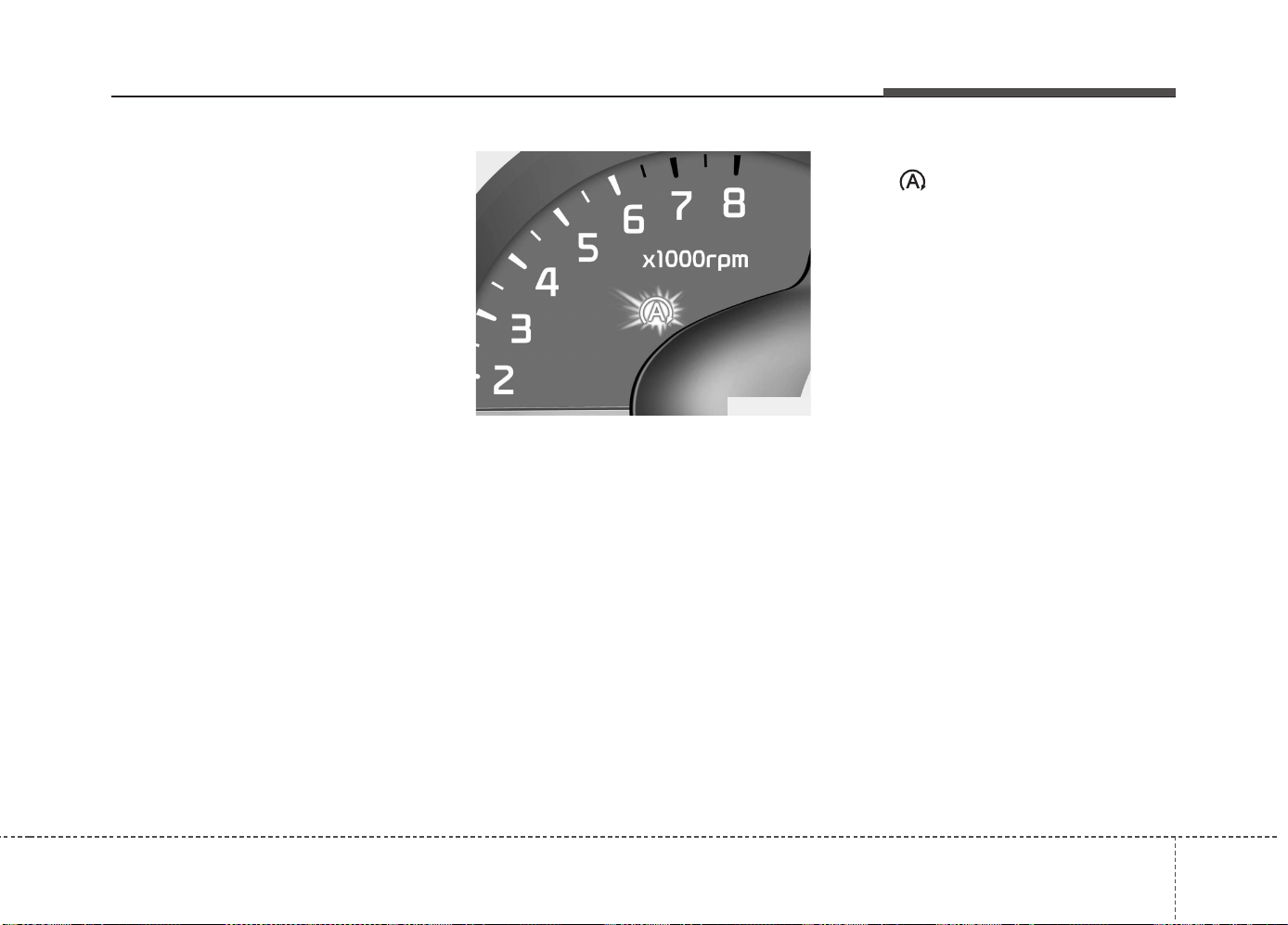
515
Driving your vehicle
Your vehicle may be equipped with the
ISG system, which reduces fuel con-
sumption by automatically shutting down
the engine, when the vehicle is at a
standstill. (For example : red light, stop
sign and traffic jam)
The engine starts automatically as soon
as the starting conditions are met.
The ISG system is ON whenever the
engine is running.
✽✽
NOTICE
When the engine automatically starts by
the ISG system, some warning lights
(ABS, ESC, ESC OFF, EPS or Parking
brake warning light) may turn on for a
few seconds.
This happens because of low battery
voltage. It does not mean the system has
malfunctioned.
Auto stop
To stop the engine in idle stop mode
1. Decrease the vehicle speed to less
than 5 km/h (3 mph).
2. Shift into N (Neutral) position.
3. Release the clutch pedal.
The engine will stop and the green AUTO
STOP( ) indicator on the instrument
cluster will illuminate.
ISG (IDLE STOP AND GO) SYSTEM (IF EQUIPPED)
OJD052026
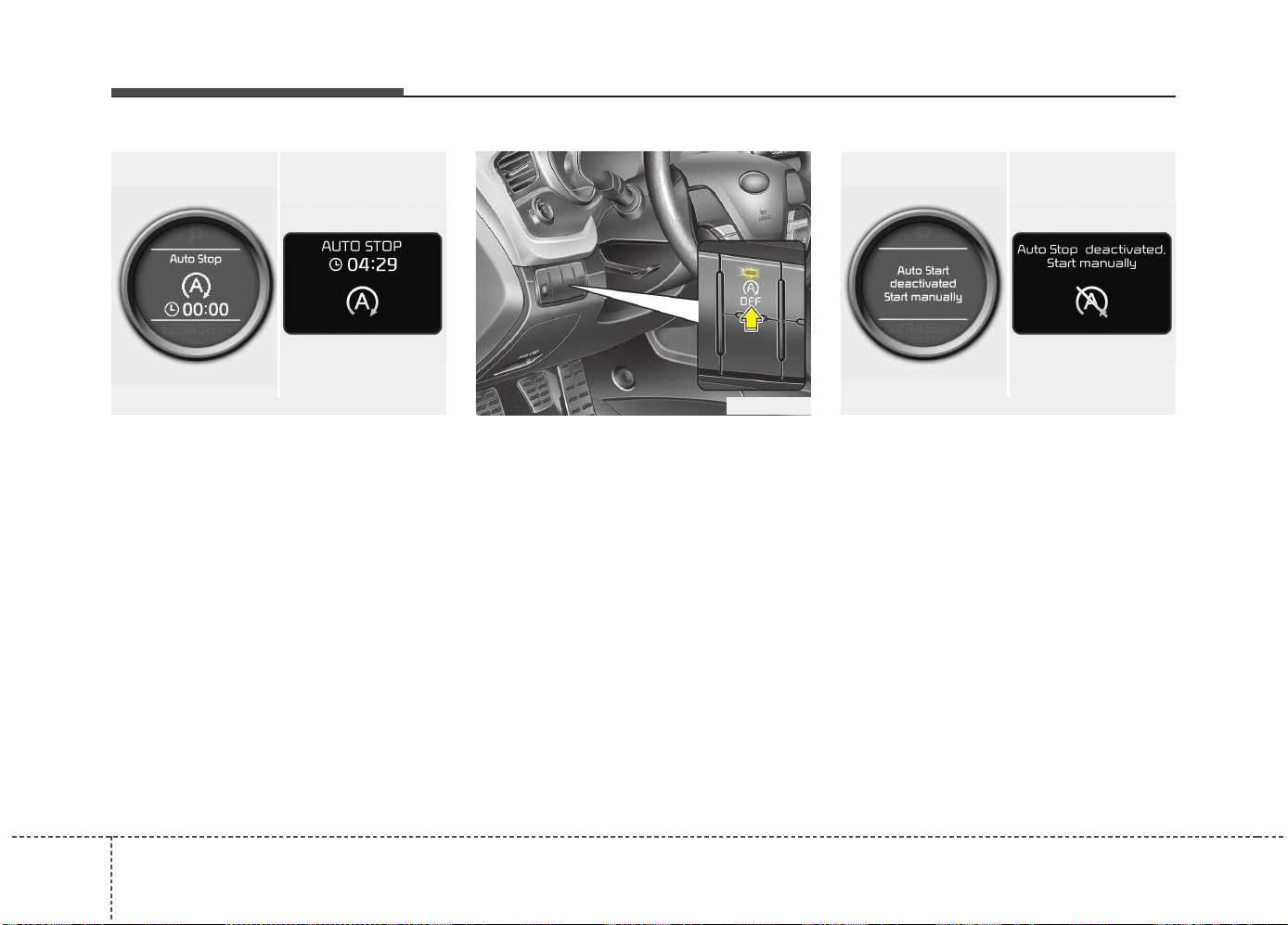
Driving your vehicle
165
Also, a message "Auto Stop" will appear
on the LCD display.
✽✽
NOTICE
You must reach a speed of at least 10
km/h (6 mph) since last idle stop.
✽
✽
NOTICE
If you unfasten the seatbelt or open the
driver's door (or engine hood) in auto
stop mode, the following will happen:
• The ISG system will deactivate (the
light on the ISG OFF button will illu-
minate).
(Continued)
(Continued)
• A message "Auto Start Deactivated
Start Manually" will appear on the
LCD display.
OJD055003
■ Normal vision
■ Supervision
■ Normal vision
■ Supervision
OJD052036/OUM054111L OJD052040/OUM054120L
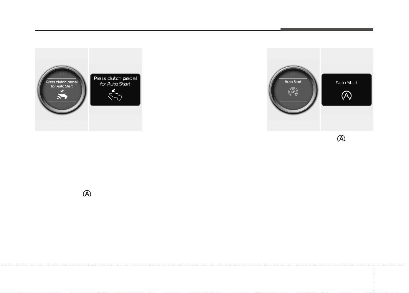
517
Driving your vehicle
Auto Start
To restart the engine from idle stop
mode
• Press the clutch pedal when the shift
lever is in the N (Neutral) position.
• A message "Press Clutch Pedal for Auto
Start" will appear on the LCD display.
• The engine will start and the green
AUTO STOP ( ) indicator on the
instrument cluster will go out.
The engine will also restart automati-
cally without the driver’s any actions
if the following occurs:
- The fan speed of manual climate con-
trol system is set above the 3rd position
when the air conditioning is on.
- The fan speed of automatic climate
control system is set above the 6th
position when the air conditioning is on.
- When a certain amount of time has
passed with the climate control system
on.
- When the defroster is on.
- The brake vaccum pressure is low.
- The battery charging status is low.
- The vehicle speed exceeds 5 km/h
(3 mph).
The green AUTO STOP ( ) indicator
on the instrument cluster will blink for 5
seconds and a message “Auto Start” will
appear on the LCD display.
OJD052041/OUM054175L
■ Normal vision
■ Supervision
OJD052037/OUM054118L
■ Normal vision
■ Supervision
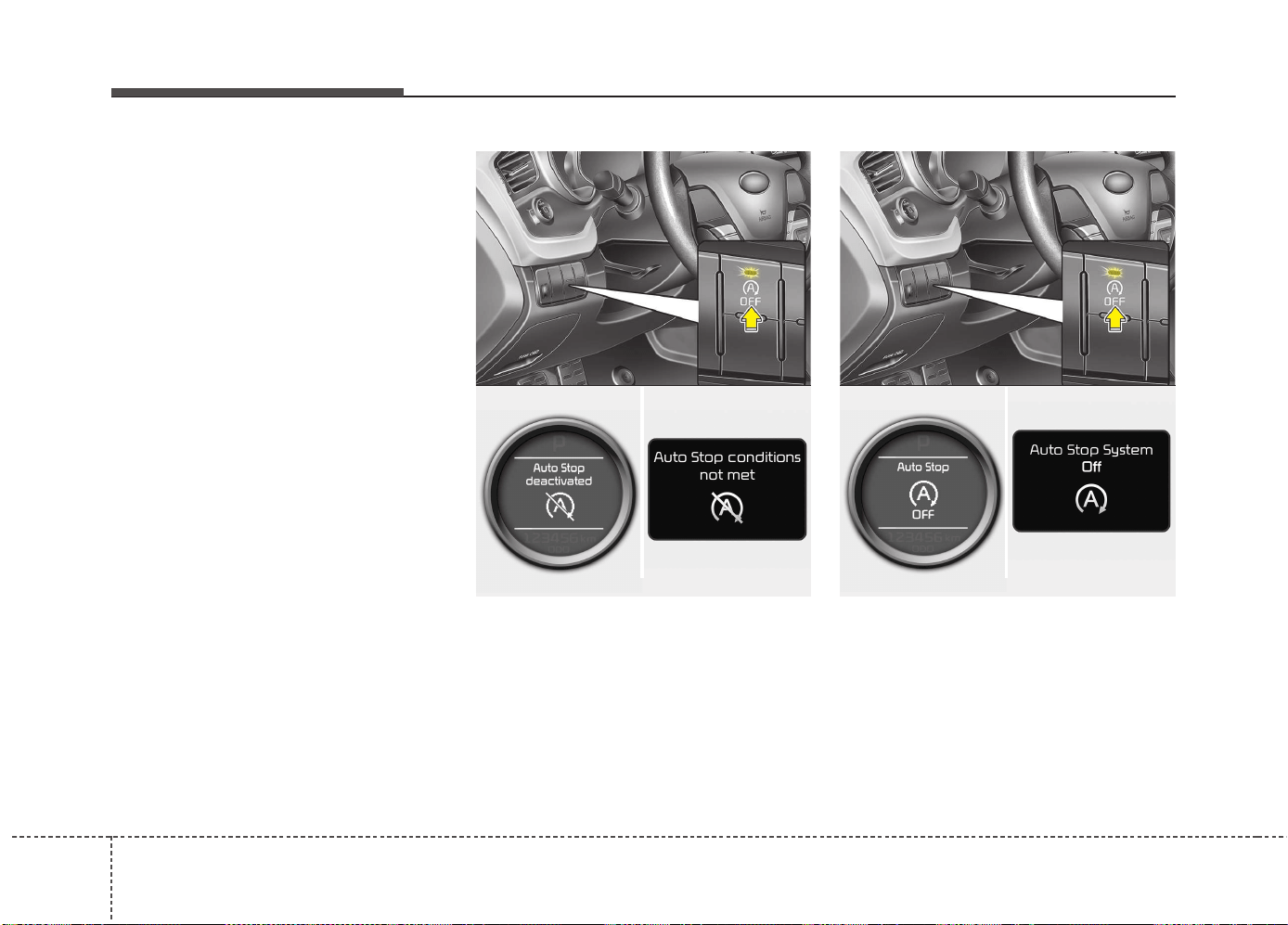
Driving your vehicle
185
Condition of ISG system opera-
tion
The ISG system will operate under
the following condition:
- The driver’s seat belt is fastened.
- The driver’s door and engine hood are
closed.
- The brake vaccum pressure is ade-
quate.
- The battery is sufficiently charged.
- The outside temperature is between
-2°C to 35°C (28.4°F to 95°F).
- The engine coolant temperature is not
too low.
✽✽
NOTICE
• If the ISG system does not meet the
operation condition, the ISG system is
deactivated. The light on the ISG OFF
button will illuminate and a message
“Auto Stop Deactivated” or “ Auto
Stop conditions not met” will appear
on the LCD display.
• If the light or notice comes on contin-
uously, please check the operation
condition.
ISG system deactivation
• If you wish to deactivate the ISG sys-
tem, press the ISG OFF button. The
light on the ISG OFF button will illumi-
nate and a message “Auto Stop OFF”
will appear on the LCD display.
• If you press the ISG OFF button again,
the system will be activated and the
light on the ISG OFF button will turn off.
■ Normal vision
■ Supervision
OJD055003/OJD052038/OUM054159L
■ Normal vision
■ Supervision
OJD055003/OJD052039/OUM054116L
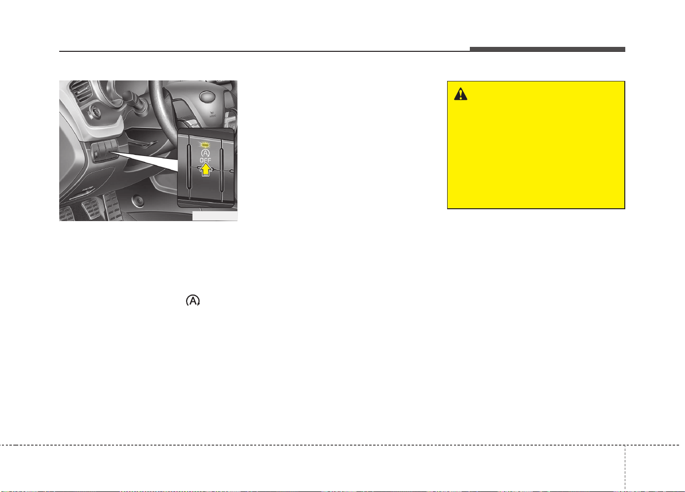
519
Driving your vehicle
ISG system malfunction
The system may not operate when:
The ISG related sensors or system error
occurs.
The following will happen:
• The yellow AUTO STOP ( ) indica-
tor on the instrument cluster will stay
on after blinking for 5 seconds.
• The light on the ISG OFF button will
illuminate.
✽✽
NOTICE
• If the ISG OFF button light is not
turned off by pressing the ISG OFF but-
ton again or if the ISG system continu-
ously does not work correctly, we rec-
ommend that you contact an authorized
Kia dealer as soon as possible.
• When the ISG OFF button light comes
on, it may stop illuminating after driv-
ing your vehicle at approximately 80
km/h for a maximum of two hours and
setting the fan speed control knob
below the 2nd position. If the ISG OFF
button light continues to be illuminat-
ed in spite of the procedure, we recom-
mend that you contact an authorized
Kia dealer as soon as possible.
WARNING
When the engine is in Idle Stop
mode, it's possible to restart the
engine without the driver taking
any action.
Before leaving the car or doing any-
thing in the engine room area, stop
the engine by turning the ignition
switch to the LOCK/OFF position or
removing the ignition key.
OJD055003
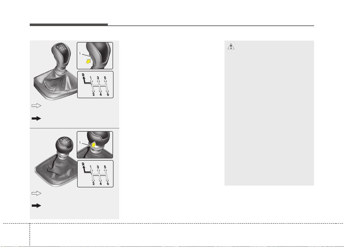
Driving your vehicle
205
Manual transaxle operation
• The manual transaxle has 6 forward
gears.
This shift pattern is imprinted on the
shift knob. The transaxle is fully syn-
chronized in all forward gears so shift-
ing to either a higher or a lower gear is
easily accomplished.
• Depress the clutch pedal down fully
while shifting, then release it slowly.
If your vehicle is equipped with an igni-
tion lock switch, the engine will not
start when starting the engine without
depressing the clutch pedal.
• The shift lever must return to the neutral
position before shifting into R (Reverse).
The button located immediately below
the shift knob must be pushed upward
(Type A) or the ring located below the
shift knob must be pulled upward (Type
B). while moving the shift lever to the R
(Reverse) position.
•
Make sure the vehicle is completely
stopped before shifting into R
(Reverse).
Never operate the engine with the
tachometer (rpm) in the red zone.
MANUAL TRANSAXLE (IF EQUIPPED)
CAUTION
• When downshifting from 5 (Fifth)
gear to 4 (Fourth) gear, caution
should be taken not to inadvertent-
ly move the shift lever sideways in
such a manner that second gear is
engaged. Such a drastic downshift
may cause the engine speed to
increase to the point that the
tachometer will enter the red-zone.
Such over-revving of the engine
may possibly cause engine and
transaxle damage.
• Do not downshift more than 2
gears or downshift the gear when
the engine is running at high
speed (5,000 RPM or higher). Such
a downshifting may damage the
engine, clutch and the transaxle.
• When shifting between 5th and
6th gear, you should always push
the gear level all the way to the
right. You could otherwise shift
unintentionally into 3rd or 4th
gear and damage the transaxle.
The button (1) must be pushed while
moving the shift lever.
The shift lever can be moved without
pushing the button (1).
■ Type B
■ Type A
The shift lever can be moved without
pulling the ring (1).
The ring (1) must be pulled while
moving the shift lever.
OJD053058
OJD055004
521
Driving your vehicle
• During cold weather, shifting may be
difficult until the transaxle lubricant has
warmed up. This is normal and not
harmful to the transaxle.
• If you've come to a complete stop and
it's hard to shift into 1 (First) or R
(Reverse), put the shift lever in neutral
position and release the clutch. Press
the clutch pedal back down, and then
shift into 1 (First) or R (Reverse) gear
position.
Using the clutch
The clutch pedal should be depressed all
the way to the floor before shifting, then
released slowly. The clutch pedal should
always be fully released while driving. Do
not rest your foot on the clutch pedal
while driving. This can cause unneces-
sary wear. Do not partially engage the
clutch to hold the vehicle on an incline.
This causes unnecessary wear. Use the
foot brake or parking brake to hold the
vehicle on an incline. Do not operate the
clutch pedal rapidly and repeatedly.
CAUTION
• To avoid premature clutch wear
and damage, do not drive with
your foot resting on the clutch
pedal. Also, don’t use the clutch
to hold the vehicle stopped on an
uphill grade, while waiting for a
traffic light, etc.
• Do not use the shift lever as a
handrest during driving, as this
can result in premature wear of
the transaxle shift forks.
• To prevent possible damage to the
clutch system, do not start with the
2nd (second) gear engaged except
when you start on a slippery road.
WARNING
• Before leaving the driver’s seat,
always set the parking brake fully
and shut the engine off. Then
make sure the transaxle is shifted
into 1 (First) gear when the vehi-
cle is parked on a level or uphill
grade, and shifted into R
(Reverse) on a downhill grade.
Unexpected and sudden vehicle
movement can occur if these pre-
cautions are not followed in the
order identified.
• If your vehicle has a manual
transaxle not equipped with a
ignition lock switch, it may move
and cause a serious accident
when starting the engine without
depressing the clutch pedal while
the parking brake is released and
the shift lever not in the neutral
position.
CAUTION
When operating the clutch pedal,
depress the clutch pedal down fully.
If you don’t depress the clutch
pedal fully, the clutch may be dam-
aged or noise may occur.
Driving your vehicle
225
Downshifting
When you must slow down in heavy traf-
fic or while driving up steep hills, down-
shift before the engine starts to labor.
Downshifting reduces the chance of
stalling and gives better acceleration
when you again need to increase your
speed. When the vehicle is traveling
down steep hills, downshifting helps
maintain safe speed and prolongs brake
life.
Good driving practices
• Never take the vehicle out of gear and
coast down a hill. This is extremely
hazardous. Always leave the vehicle in
gear.
• Don't "ride" the brakes. This can cause
them to overheat and malfunction.
Instead, when you are driving down a
long hill, slow down and shift to a lower
gear. When you do this, engine braking
will help slow down the vehicle.
• Slow down before shifting to a lower
gear. This will help avoid over-revving
the engine, which can cause damage.
• Slow down when you encounter cross
winds. This gives you much better con-
trol of your vehicle.
• Be sure the vehicle is completely
stopped before you attempt to shift into
R (Reverse). The transaxle can be dam-
aged if you do not. To shift into R
(Reverse), depress the clutch, move the
shift lever to neutral, wait three seconds,
then shift to the R (Reverse) position.
• Exercise extreme caution when driving
on a slippery surface. Be especially
careful when braking, accelerating or
shifting gears. On a slippery surface,
an abrupt change in vehicle speed can
cause the drive wheels to lose traction
and the vehicle to go out of control.
WARNING
• Always buckle-up! In a collision,
an unbelted occupant is signifi-
cantly more likely to be seriously
injured or killed than a properly
belted occupant.
• Avoid high speeds when corner-
ing or turning.
• Do not make quick steering
wheel movements, such as sharp
lane changes or fast, sharp turns.
• The risk of rollover is greatly
increased if you lose control of
your vehicle at highway speeds.
• Loss of control often occurs if
two or more wheels drop off the
roadway and the driver over-
steers to reenter the roadway.
• In the event your vehicle leaves
the roadway, do not steer sharply.
Instead, slow down before pulling
back into the travel lanes.
• Never exceed posted speed lim-
its.
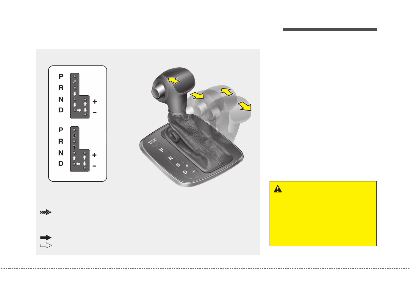
523
Driving your vehicle
Automatic transaxle operation
The highly efficient automatic transaxle
has 6 forward speeds and one reverse
speed. The individual speeds are select-
ed automatically, depending on the posi-
tion of the shift lever.
✽✽
NOTICE
The first few shifts on a new vehicle, if
the battery has been disconnected, may
be somewhat abrupt. This is a normal
condition, and the shifting sequence will
adjust after shifts are cycled a few times
by the TCM (Transaxle Control Module)
or PCM (Powertrain Control Module).
For smooth operation, depress the brake
pedal when shifting from N (Neutral) to a
forward or reverse gear.
AUTOMATIC TRANSAXLE (IF EQUIPPED)
OJD052005
+
+
++
((
((
UU
UU
PP
PP
))
))
--
--
((
((
DD
DD
OO
OO
WW
WW
NN
NN
))
))
The shift lever can be shifted freely.
Press the lock release button when shifting.
Depress the brake pedal and the lock release button when shifting.
(If the shift lock system is not equipped, it is not necessary to depress the brake pedal.
However, it is recommended to depress the brake pedal to avoid inadvertent movement
of the vehicle.)
WARNING - Automatic
transaxle
• Always check the surrounding
areas near your vehicle for peo-
ple, especially children, before
shifting a vehicle into D (Drive) or
R (Reverse).
(Continued)
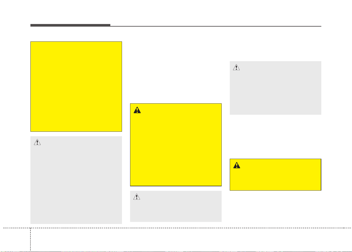
Driving your vehicle
245
Transaxle ranges
The indicator lights in the instrument clus-
ter displays the shift lever position when
the ignition switch is in the ON position.
P (Park)
Always come to a complete stop before
shifting into P (Park). This position locks
the transaxle and prevents the front
wheels from rotating.
R (Reverse)
Use this position to drive the vehicle
backward.
N (Neutral)
The wheels and transaxle are not
engaged. The vehicle will roll freely even
on the slightest incline unless the parking
brake or service brakes are applied.
(Continued)
• Before leaving the driver’s seat,
always make sure the shift lever
is in the P (Park) position; then
set the parking brake fully and
shut the engine off. Unexpected
and sudden vehicle movement
can occur if these precautions
are not followed in the order iden-
tified.
• Do not use the engine brake
(shifting from a high gear to
lower gear) rapidly on slippery
roads. The vehicle may slip caus-
ing an accident.
CAUTION
• To avoid damage to your
transaxle, do not accelerate the
engine in R (Reverse) or any for-
ward gear position with the
brakes on.
• When stopped on an upgrade, do
not hold the vehicle stationary
with engine power. Use the serv-
ice brake or the parking brake.
• Do not shift from N (Neutral) or P
(Park) into D (Drive), or R
(Reverse) when the engine is
above idle speed.
WARNING
• Shifting into P (Park) while the
vehicle is in motion will cause the
drive wheels to lock which will
cause you to lose control of the
vehicle.
• Do not use the P (Park) position
in place of the parking brake.
Always make sure the shift lever
is latched in the P (Park) position
and set the parking brake fully.
• Never leave a child unattended in
a vehicle.
CAUTION
The transaxle may be damaged if
you shift into P (Park) while the
vehicle is in motion.
CAUTION
Always come to a complete stop
before shifting into or out of R
(Reverse); you may damage the
transaxle if you shift into R (Reverse)
while the vehicle is in motion, except
as explained in “Rocking the vehi-
cle”, in this manual.
WARNING
Do not drive with the shift lever in N
(Neutral). The engine brake will not
work and lead to an accident.

525
Driving your vehicle
- Parking in N (Neutral) gear
Follow below steps when parking and
you want the vehicle to move when
pushed.
1.After parking your vehicle, depress the
brake pedal and move the shift lever to
[P] with the ignition button in [ON] or
while the engine is running.
2.If the parking brake is applied unlock
the parking brake.
- For EPB (Electronic Parking Brake)
equipped vehicles, push the brake
pedal with the ignition button in [ON]
or while the engine is running to dis-
engage the parking brake. If [AUTO
HOLD] function is used while driving
(If [AUTO HOLD] indicator is on in the
cluster), press [AUTO HOLD] switch
and [AUTO HOLD] function should be
turn off.
3.While pressing the brake pedal, turn
the ignition button [OFF].
- For smart key equipped vehicles, the
ignition switch can be moved to [OFF]
only when the shift lever is in [P].
4.Change the gear shift lever to [N]
(Neutral) while pressing the brake pedal
and pushing [SHIFT LOCK RELEASE]
button or inserting, pressing down a tool
(e.g. flathead screw-driver) into the
[SHIFT LOCK RELEASE] access hole
at the same time. Then, the vehicle will
move when external force is applied.
(Continued)
• After the ignition switch has
been turned off, the electronic
parking brake cannot be dis-
engaged.
• For EPB (Electronic Parking Brake)
equipped vehicles with [AUTO
HOLD] function used while driving,
if the ignition button has been
turned [OFF], the electronic park-
ing brake will be engaged automat-
ically.
Therefore, [AUTO HOLD] function
should be turned off before the
ignition button is turned off.
CAUTION
• With the exception of parking in
neutral gear, always park the vehi-
cle in [P] (Park) for safety and
engage the parking brake.
• Before parking in [N] (Neutral)
gear, first make sure the parking
ground is level and flat. Do not
park in [N] gear on any slopes or
gradients.
If parked and left in [N], the vehi-
cle may move and cause serious
damage and injury.
(Continued)
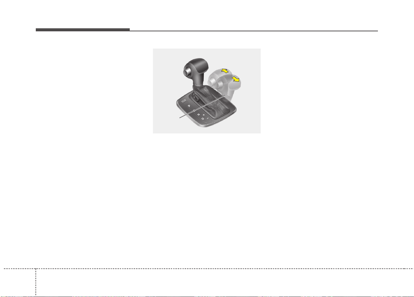
Driving your vehicle
265
D (Drive)
This is the normal forward driving posi-
tion. The transaxle will automatically shift
through a 6-gear sequence, providing the
best fuel economy and power.
For extra power when passing another
vehicle or climbing grades, depress the
accelerator pedal fully (more than 80%)
until the kick down mechanism works
with a clicking noise, at which time the
transaxle will automatically downshift to
the next lower gear.
✽✽
NOTICE
• Always come to a complete stop
before shifting into D (Drive).
• A clicking noise heard from the kick
down mechanism by depressing the
accelerator pedal fully is a normal
condition.
Sports mode
Whether the vehicle is stationary or in
motion, sports mode is selected by push-
ing the shift lever from the D (Drive) posi-
tion into the manual gate. To return to D
(Drive) range operation, push the shift
lever back into the main gate.
In sports mode, moving the shift lever
backwards and forwards will allow you to
make gearshifts rapidly. In contrast to a
manual transaxle, the sports mode
allows gearshifts with the accelerator
pedal depressed.
Up (+) : Push the lever forward once to
shift up one gear.
Down (-) : Pull the lever backwards once
to shift down one gear.
✽✽
NOTICE
• In sports mode, the driver must exe-
cute upshifts in accordance with road
conditions, taking care to keep the
engine speed below the red zone.
• In sports mode, only the 6 forward
gears can be selected. To reverse or
park the vehicle, move the shift lever
to the R (Reverse) or P (Park) position
as required.
• In sports mode, downshifts are made
automatically when the vehicle slows
down. When the vehicle stops, 1st gear
is automatically selected.
• In sports mode, when the engine rpm
approaches the red zone shift points
are varied to upshift automatically.
• To maintain the required levels of
vehicle performance and safety, the
system may not execute certain
gearshifts when the shift lever is oper-
ated.
• When driving on a slippery road,
push the shift lever forward into the
+(up) position. This causes the
transaxle to shift into the 2nd gear
which is better for smooth driving on
a slippery road. Push the shift lever to
the -(down) side to shift back to the 1st
gear.
OJD052006
Sports
mode
+
+
++
((
((
UU
UU
PP
PP
))
))
--
--
((
((
DD
DD
OO
OO
WW
WW
NN
NN
))
))
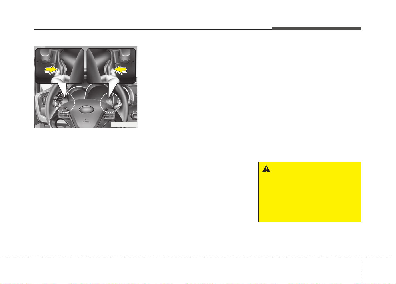
527
Driving your vehicle
Paddle shifter (if equipped)
The paddle shifter is available when the
shift lever is in the D (Drive) position or
the sports mode.
With the shift lever in the D position
The paddle shifter will operate when the
vehicle speed is more than 10km/h.
Pull the [+] or [-] paddle shifter once to
shift up or down one gear and the system
changes from automatic mode to manual
mode.
When the vehicle speed is lower than
10km/h, if you depress the accelerator
pedal for more than 5 seconds or if you
shift the shift lever from D (Drive) to
sports mode and shift it from sports
mode to D (Drive) again, the system
changes from manual mode to automatic
mode.
With the shift lever in the sports mode
Pull the [+] or [-] paddle shifter once to
shift up or down one gear.
✽✽
NOTICE
If you pull the [+] and [-] paddle shifters
at the same time, you cannot shift the
gear.
Shift lock system (if equipped)
For your safety, the automatic transaxle
has a shift lock system which prevents
shifting the transaxle from P (Park) or N
(Neutral) into R (Reverse) unless the
brake pedal is depressed.
To shift the transaxle from P (Park) or N
(Neutral) into R (Reverse):
1. Depress and hold the brake pedal.
2. Start the engine or turn the ignition
switch to the ON position.
3. Move the shift lever.
If the brake pedal is repeatedly
depressed and released with the shift
lever in the P (Park) position, a chattering
noise near the shift lever may be heard.
This is a normal condition.
OJD052025
WARNING
Always fully depress the brake
pedal before and while shifting out
of the P (Park) position into anoth-
er position to avoid inadvertent
motion of the vehicle which could
injure persons in or around the
vehicle.
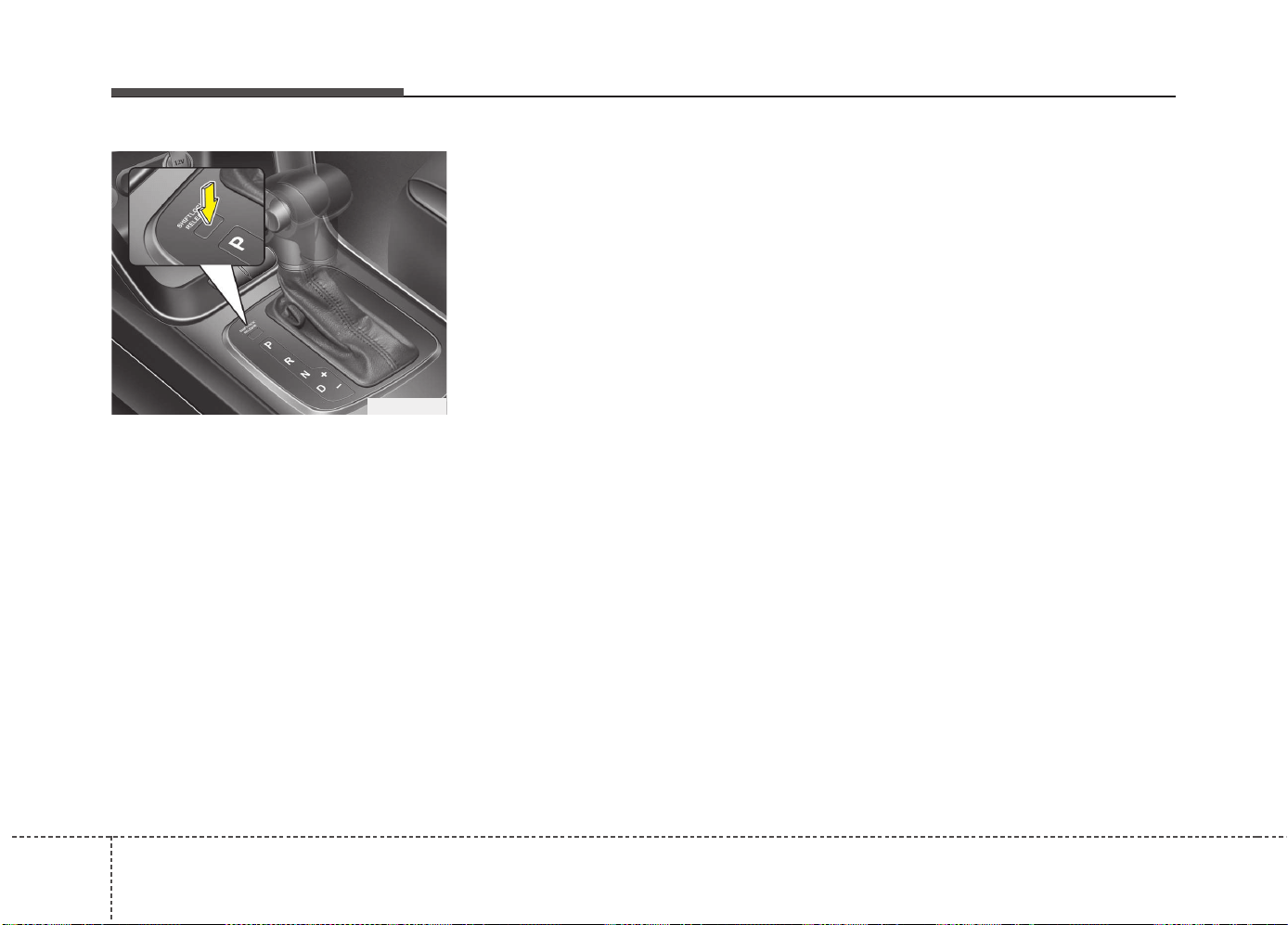
Driving your vehicle
285
Shift-lock override
If the shift lever cannot be moved from
the P (Park) or N (Neutral) position into R
(Reverse) position with the brake pedal
depressed, continue depressing the
brake, then do the following:
1. Press the shift-lock release button.
2. Move the shift lever.
3. We recommend that the system be
inspected by an authorized Kia dealer.
Ignition key interlock system
(if equipped)
The ignition key cannot be removed
unless the shift lever is in the P (Park)
position.
Good driving practices
• Never move the shift lever from P
(Park) or N (Neutral) to any other posi-
tion with the accelerator pedal
depressed.
• Never move the shift lever into P (Park)
when the vehicle is in motion.
• Be sure the vehicle is completely
stopped before you attempt to shift into
R (Reverse) or D (Drive).
• Never take the vehicle out of gear and
coast down a hill. This may be
extremely hazardous. Always leave the
vehicle in gear when moving.
• Do not "ride" the brakes. This can
cause them to overheat and malfunc-
tion. Instead, when you are driving
down a long hill, slow down and shift to
a lower gear. When you do this, engine
braking will help slow down the vehicle.
• Slow down before shifting to a lower
gear. Otherwise, the lower gear may
not be engaged.
• Always use the parking brake. Do not
depend on placing the transaxle in P
(Park) to keep the vehicle from moving.
• Exercise extreme caution when driving
on a slippery surface. Be especially
careful when braking, accelerating or
shifting gears. On a slippery surface,
an abrupt change in vehicle speed can
cause the drive wheels to lose traction
and the vehicle to go out of control.
• Optimum vehicle performance and
economy is obtained by smoothly
depressing and releasing the accelera-
tor pedal.
OJD052007
529
Driving your vehicle
Moving up a steep grade from a stand-
ing start
To move up a steep grade from a stand-
ing start, depress the brake pedal, shift
the shift lever to D (Drive). Select the
appropriate gear depending on load
weight and steepness of the grade, and
release the parking brake. Depress the
accelerator gradually while releasing the
service brakes.
When accelerating from a stop on a
steep hill, the vehicle may have a ten-
dency to roll backwards. Shifting the
shift lever into 2 (Second Gear) will
help prevent the vehicle from rolling
backwards.
WARNING
If your vehicle becomes stuck in
snow, mud, sand, etc., then you
may attempt to rock the vehicle free
by moving it forward and backward.
Do not attempt this procedure if
people or objects are anywhere
near the vehicle. During the rocking
operation the vehicle may suddenly
move forward of backward as it
becomes unstuck, causing injury
or damage to nearby people or
objects.
WARNING
• Always buckle-up! In a collision,
an unbelted occupant is signifi-
cantly more likely to be seriously
injured or killed than a properly
belted occupant.
• Avoid high speeds when corner-
ing or turning.
• Do not make quick steering
wheel movements, such as sharp
lane changes or fast, sharp turns.
• The risk of rollover is greatly
increased if you lose control of
your vehicle at highway speeds.
• Loss of control often occurs if
two or more wheels drop off the
roadway and the driver over-
steers to reenter the roadway.
• In the event your vehicle leaves
the roadway, do not steer sharply.
Instead, slow down before pulling
back into the travel lanes.
• Never exceed posted speed lim-
its.
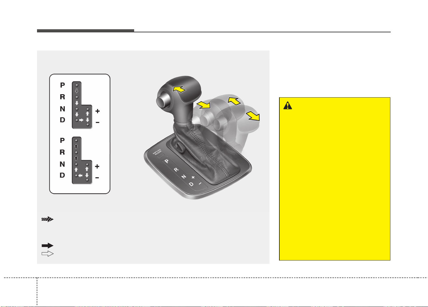
Driving your vehicle
305
DUAL CLUTCH TRANSMISSION (DCT) (IF EQUIPPED)
Dual clutch transmission opera-
tion
The dual clutch transmission has 7 (or 6)
forward speeds and one reverse speed.
The individual speeds are selected auto-
matically in the D (Drive) position.
OJD052005
+
+
++
((
((
UU
UU
PP
PP
))
))
--
--
((
((
DD
DD
OO
OO
WW
WW
NN
NN
))
))
The shift lever can be shifted freely.
Press the lock release button when shifting.
Depress the brake pedal and the lock release button when shifting.
(If the shift lock system is not equipped, it is not necessary to depress the brake pedal.
However, it is recommended to depress the brake pedal to avoid inadvertent movement
of the vehicle.)
WARNING
To reduce the risk of serious injury
or death:
• ALWAYS check the surrounding
areas near your vehicle for peo-
ple, especially children, before
shifting a vehicle into D (Drive) or
R (Reverse).
• Before leaving the driver’s seat,
always make sure the shift lever
is in the P (Park) position, then
set the parking brake, and place
the ignition switch in the
LOCK/OFF position. Unexpected
and sudden vehicle movement
can occur if these precautions
are not followed.
• Do not use engine braking (shift-
ing from a high gear to lower
gear) rapidly on slippery roads.
The vehicle may slip causing an
accident.
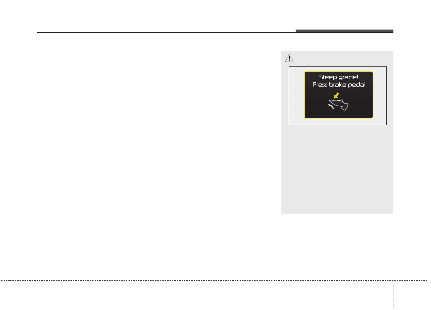
531
Driving your vehicle
• The Dual Clutch Transmission gives
the driving feel of a manual transmis-
sion, yet provides the ease of a fully
automatic transmission. Unlike a tradi-
tional automatic transmission, the gear
shifting can be felt (and heard) on the
dual clutch transmission
- Think of it as an automatically shifting
manual transmission.
- Shift into Drive range and get fully
automatic shifting, similar to a con-
ventional automatic transmission.
• Dual clutch transmission adopts dry-
type dual clutch, which is different from
torque converter of automatic trans-
mission, and shows better acceleration
performance during driving. But, initial
launch might be little bit slower than
Automatic Transmission.
• The dry-type clutch transfers torque
and provides a direct driving feeling
which may feel different from a con-
ventional automatic transmission with
a torque converter. This may be more
noticeable when starting from a stop or
low vehicle speed.
• When rapidly accelerating at low vehi-
cle speed, engine could rev at high rpm
depending on vehicle drive condition.
• For smooth launch uphill, press down
the accelerator pedal smoothly
depending on the current conditions.
• If you release your foot from the accel-
erator pedal at low vehicle speed, you
may feel strong engine brake, which is
similar to manual transmission.
• When driving downhill, you may use
Sports Mode and press the paddle
shifters to downshift to a lower gear in
order to control your speed without
using the brake pedal excessively.
• When you turn the engine on and off,
you may hear clicking sounds as the
system goes through a self test. This is
a normal sound for the Dual Clutch
Transmission.
CAUTION
• To hold the vehicle on a hill use
the foot brake or the parking
brake. If the vehicle is held by
applying the accelerator pedal on
a hill the clutch and transmission
will be overheated resulting in
damage.
At this time, a warning message
will appear on the LCD display
and you may feel a vibration.
(Continued)
OJD055176L
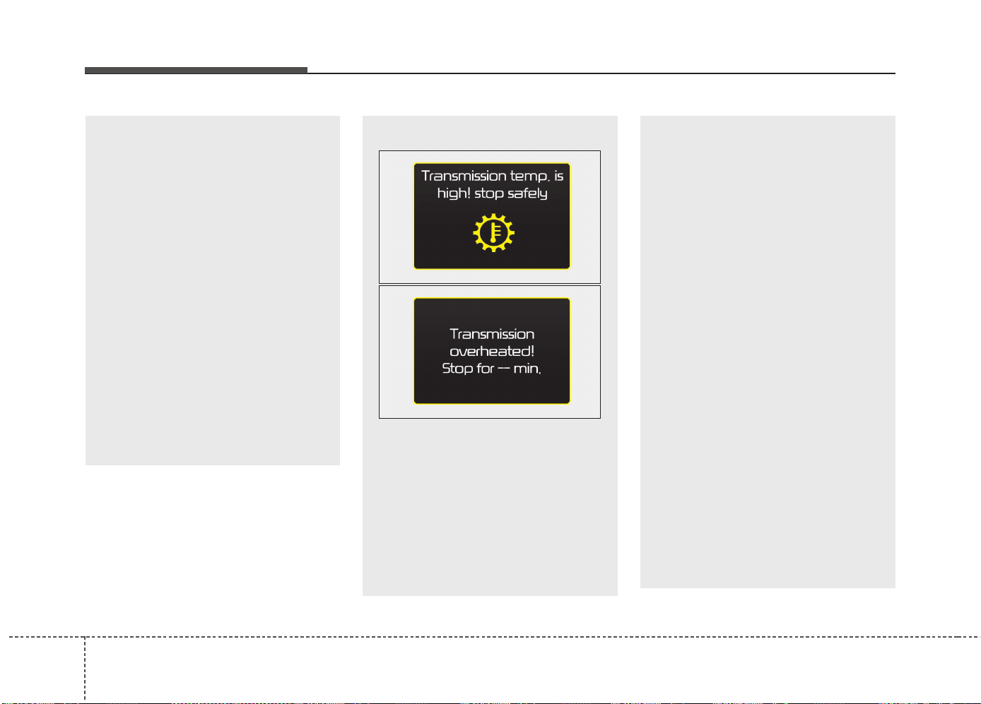
Driving your vehicle
325
(Continued)
• If the clutch becomes overheated
by excessive use of the clutch to
hold on a hill, you may notice a
shudder feeling and a blinking
display on the instrument cluster.
When this occurs, the clutch is
disabled until the clutch cools to
normal temperatures. If this
occurs, pull over to a safe loca-
tion, shift into P (Park) and apply
the foot brake for a few minutes.
• If the LCD warning is active, the
foot brake must be applied.
• Ignoring the warnings can lead to
damage to the transmission.
• If the display continues to blink,
for your safety, we recommend
that you contact an authorized
Kia dealer.
(Continued)
(Continued)
• Under certain conditions such as
repeated launch on steep grades,
the clutch in the transmission
could overheat. When the clutch
is overheated, the safe protection
mode engages. If the safe protec-
tion mode engages, the gear posi-
tion indicator on the cluster
blinks with a chime sound.
(Continued)
OJD055175L
OJD055177L
(Continued)
At this time, a warning message
will appear on the LCD display
and driving may not be smooth.
If you ignore this warning, the
driving condition may become
worse. To return the normal driv-
ing condition, stop the vehicle
and apply the foot brake for a few
minutes before driving off.
• Gear shifts may be more notice-
able than a conventional automat-
ic transmission. This is a normal
characteristic of this type of dual
clutch transmission.
• The overheated Dual clutch trans-
mission may change the gear
shifting characteristics, and illumi-
nate the warning message on the
LCD display under the conditions
that operation of the kickdown
mechanism is repetitively used.
• Do not use the kickdown mecha-
nism to return to the normal driv-
ing condition. Also, temporarily
stop the vehicle at a safe location,
when the warning message illu-
minates on the LCD display.
(Continued)
533
Driving your vehicle
The indicator in the instrument cluster
displays the shift lever position when the
ignition switch is in the ON position.
P (Park)
Always come to a complete stop before
shifting into P (Park).
To shift from P (Park), you must depress
firmly on the brake pedal and make sure
your foot is off the accelerator pedal.
The shift lever must be in P (Park) before
turning the engine off.
R (Reverse)
Use this position to drive the vehicle
backward.
N (Neutral)
The wheels and transmission are not
engaged.
Use N (Neutral) if you need to restart a
stalled engine, or if it is necessary to stop
with the engine ON. Shift into P (Park) if
you need to leave your vehicle for any
reason.
Always depress the brake pedal when
you are shifting from N (Neutral) to
another gear.
WARNING
• Shifting into P (Park) while the
vehicle is in motion may cause
you to lose control of the vehicle.
• After the vehicle has stopped,
always make sure the shift lever
is in P (Park), apply the parking
brake, and turn the engine off.
• Do not use the P (Park) position
in place of the parking brake.
(Continued)
• During the first 1,500 km (1,000
miles), you may feel that the vehi-
cle may not be smooth when
accelerating at low speed. During
this break-in period, the shift qual-
ity and performance of your new
vehicle is continuously optimized.
• Always come to a complete stop
before shifting into D (Drive) or R
(Reverse).
• Do not put the shift lever in N
(Neutral) while driving.
CAUTION
Always come to a complete stop
before shifting into or out of R
(Reverse); you may damage the
transmission if you shift into R
(Reverse) while the vehicle is in
motion.
WARNING
Do not shift into gear unless your
foot is firmly on the brake pedal.
Shifting into gear when the engine
is running at high speed can cause
the vehicle to move very rapidly.
You could lose control of the vehi-
cle and hit people or objects.
WARNING
Do not drive with the shift lever in N
(Neutral).
The engine brake will not work and
lead to an accident.
Driving your vehicle
345
- Parking in N (Neutral) gear
Follow below steps when parking and
you want the vehicle to move when
pushed.
1.After parking your vehicle, depress the
brake pedal and move the shift lever to
[P] with the ignition button in [ON] or
while the engine is running.
2.If the parking brake is applied unlock
the parking brake.
- For EPB (Electronic Parking Brake)
equipped vehicles, push the brake
pedal with the ignition button in [ON]
or while the engine is running to dis-
engage the parking brake. If [AUTO
HOLD] function is used while driving
(If [AUTO HOLD] indicator is on in the
cluster), press [AUTO HOLD] switch
and [AUTO HOLD] function should be
turn off.
3.While pressing the brake pedal, turn
the ignition button [OFF].
- For smart key equipped vehicles, the
ignition switch can be moved to [OFF]
only when the shift lever is in [P].
4.Change the gear shift lever to [N]
(Neutral) while pressing the brake pedal
and pushing [SHIFT LOCK RELEASE]
button or inserting, pressing down a tool
(e.g. flathead screw-driver) into the
[SHIFT LOCK RELEASE] access hole
at the same time. Then, the vehicle will
move when external force is applied.
D (Drive)
This is the normal driving position. The
transmission will automatically shift
through a 7 (or 6) gear sequence, pro-
viding the best fuel economy and power.
For extra power when passing another
vehicle or driving uphill depress the
accelerator pedal further until you feel the
transmission downshift to a lower gear.
(Continued)
• After the ignition switch has
been turned off, the electronic
parking brake cannot be dis-
engaged.
• For EPB (Electronic Parking Brake)
equipped vehicles with [AUTO
HOLD] function used while driving,
if the ignition button has been
turned [OFF], the electronic park-
ing brake will be engaged automat-
ically.
Therefore, [AUTO HOLD] function
should be turned off before the
ignition button is turned off.
CAUTION
• With the exception of parking in
neutral gear, always park the vehi-
cle in [P] (Park) for safety and
engage the parking brake.
• Before parking in [N] (Neutral)
gear, first make sure the parking
ground is level and flat. Do not
park in [N] gear on any slopes or
gradients.
If parked and left in [N], the vehi-
cle may move and cause serious
damage and injury.
(Continued)
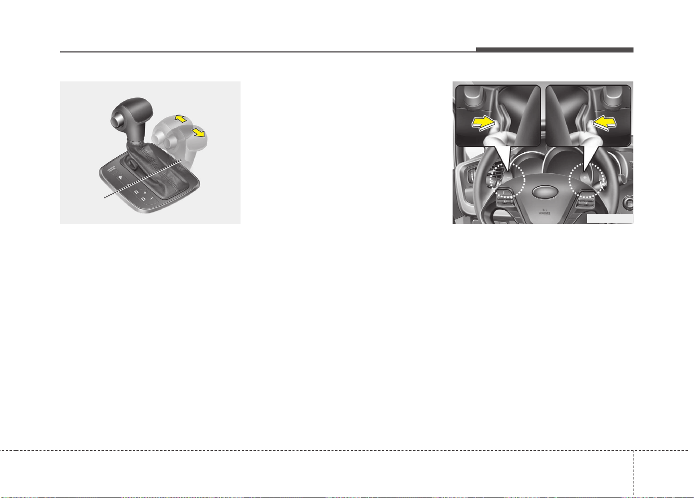
535
Driving your vehicle
Sports mode
Whether the vehicle is stationary or in
motion, sports mode is selected by push-
ing the shift lever from the D (Drive) posi-
tion into the manual gate. To return to D
(Drive) range operation, push the shift
lever back into the main gate.
In Sports Mode, moving the shift lever
backwards and forwards will allow you to
select the desired range of gears for the
current driving conditions.
+ (Up) : Push the lever forward once to
shift up one gear.
- (Down) : Pull the lever backwards once
to shift down one gear.
✽✽
NOTICE
• Only the 7 (or 6) forward gears can be
selected. To reverse or park the vehicle,
move the shift lever to the R (Reverse)
or P (Park) position as required.
• Downshifts are made automatically
when the vehicle slows down. When
the vehicle stops, 1st gear is automati-
cally selected.
• When the engine rpm approaches the
red zone the transmission will upshift
automatically.
• If the driver presses the lever to + (Up)
or - (Down) position, the transmission
may not make the requested gear
change if the next gear is outside of
the allowable engine rpm range. The
driver must execute upshifts in accor-
dance with road conditions, taking
care to keep the engine rpms below
the red zone.
Paddle shifter (if equipped)
The paddle shifter is available when the
shift lever is in the D (Drive) position or
the sports mode.
OJD052006
Sports
mode
+
+
++
((
((
UU
UU
PP
PP
))
))
--
--
((
((
DD
DD
OO
OO
WW
WW
NN
NN
))
))
OJD052025
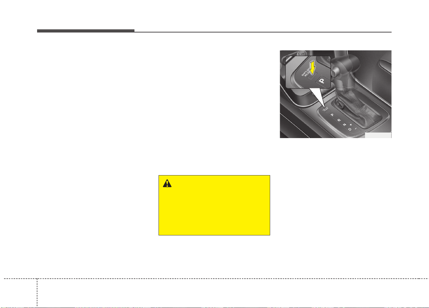
Driving your vehicle
365
With the shift lever in the D position
The paddle shifter will operate when the
vehicle speed is more than 10km/h.
Pull the [+] or [-] paddle shifter once to
shift up or down one gear and the system
changes from automatic mode to manual
mode.
When the vehicle speed is lower than
10km/h, if you depress the accelerator
pedal for more than 5 seconds or if you
shift the shift lever from D (Drive) to
sports mode and shift it from sports
mode to D (Drive) again, the system
changes from manual mode to automatic
mode.
With the shift lever in the sports mode
Pull the [+] or [-] paddle shifter once to
shift up or down one gear.
✽✽
NOTICE
If you pull the [+] and [-] paddle shifters
at the same time, you cannot shift the
gear.
Shift lock system (if equipped)
For your safety, the Dual clutch transmis-
sion has a shift lock system which pre-
vents shifting the transaxle from P (Park)
or N (Neutral) into R (Reverse) unless
the brake pedal is depressed.
To shift the transaxle from P (Park) or N
(Neutral) into R (Reverse):
1. Depress and hold the brake pedal.
2. Start the engine or turn the ignition
switch to the ON position.
3. Move the shift lever.
If the brake pedal is repeatedly
depressed and released with the shift
lever in the P (Park) position, a chattering
noise near the shift lever may be heard.
This is a normal condition.
Shift-lock override
If the shift lever cannot be moved from
the P (Park) or N (Neutral) position into R
(Reverse) position with the brake pedal
depressed, continue depressing the
brake, then do the following:
1. Press the shift-lock release button.
2. Move the shift lever.
3. We recommend that the system be
inspected by an authorized Kia dealer.
WARNING
Always fully depress the brake
pedal before and while shifting out
of the P (Park) position into anoth-
er position to avoid inadvertent
motion of the vehicle which could
injure persons in or around the car.
OJD052007

537
Driving your vehicle
Ignition key interlock system
(if equipped)
The ignition key cannot be removed
unless the shift lever is in the P (Park)
position.
Good driving practices
• Never move the shift lever from P
(Park) or N (Neutral) to any other posi-
tion with the accelerator pedal
depressed.
• Never move the shift lever into P (Park)
when the vehicle is in motion.
• Be sure the car is completely stopped
before you attempt to shift into R
(Reverse) or D (Drive).
• Never take the car out of gear and
coast down a hill. This may be
extremely hazardous. Always leave the
car in gear when moving.
• Do not "ride" the brakes. This can
cause them to overheat and malfunc-
tion. Instead, when you are driving
down a long hill, slow down and shift to
a lower gear. When you do this, engine
braking will help slow the car.
• Slow down before shifting to a lower
gear. Otherwise, the lower gear may
not be engaged.
• Always use the parking brake. Do not
depend on placing the transaxle in P
(Park) to keep the car from moving.
• Exercise extreme caution when driving
on a slippery surface. Be especially
careful when braking, accelerating or
shifting gears. On a slippery surface,
an abrupt change in vehicle speed can
cause the drive wheels to lose traction
and the vehicle to go out of control.
• Optimum vehicle performance and
economy is obtained by smoothly
depressing and releasing the accelera-
tor pedal.
Driving your vehicle
385
Moving up a steep grade from a stand-
ing start
To move up a steep grade from a stand-
ing start, depress the brake pedal, shift
the shift lever to D (Drive). Select the
appropriate gear depending on load
weight and steepness of the grade, and
release the parking brake. Depress the
accelerator gradually while releasing the
service brakes.
WARNING
If your vehicle becomes stuck in
snow, mud, sand, etc., then you may
attempt to rock the vehicle free by
moving it forward and backward. Do
not attempt this procedure if people
or objects are anywhere near the
vehicle. During the rocking opera-
tion the vehicle may suddenly move
forward of backward as it becomes
unstuck, causing injury or damage
to nearby people or objects.
WARNING
• Always buckle-up! In a collision,
an unbelted occupant is signifi-
cantly more likely to be seriously
injured or killed than a properly
belted occupant.
• Avoid high speeds when corner-
ing or turning.
• Do not make quick steering
wheel movements, such as sharp
lane changes or fast, sharp turns.
• The risk of rollover is greatly
increased if you lose control of
your vehicle at highway speeds.
• Loss of control often occurs if
two or more wheels drop off the
roadway and the driver over-
steers to reenter the roadway.
• In the event your vehicle leaves
the roadway, do not steer sharply.
Instead, slow down before pulling
back into the travel lanes.
• Never exceed posted speed lim-
its.
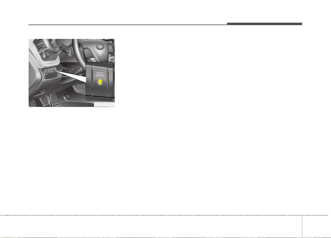
539
Driving your vehicle
Active ECO operation
Active ECO helps improve fuel efficiency
by controlling the engine and transaxle.
But fuel-efficiency can be changed by the
driver's driving habits and road conditions.
• When the Active ECO button is
pressed the ECO indicator (green) will
illuminate to show that the Active ECO
is operating.
• When the Active ECO is activated, it
does not turn off even though the
engine is restarted again. To turn off
the system, press the active ECO but-
ton again.
• If Active ECO is turned off, it will return
to the normal mode.
When Active ECO is activated :
• The acceleration may slightly be
reduced eventhough you depress the
accelerator fully.
• The air conditioner performance may
be limited.
• The shift pattern of the automatic
transaxle may change.
• The engine noise may get louder.
The above situations are normal condi-
tions when the active eco system is acti-
vated to improve fuel efficiency.
Limitation of Active ECO opera-
tion:
If the following conditions occur while
Active ECO is operating, the system
operation is limited even though there is
no change in the ECO indicator.
• When the coolant temperature is low:
The system will be limited until engine
performance becomes normal.
• When driving up a hill: The system will
be limited to gain power when driving
uphill because the engine torque is
restricted.
• When using sports mode: The system
will be limited according to the shift
location.
• When the accelerator pedal is deeply
pressed for a few seconds: The system
will be limited, judging that the driver
wants to speed up.
ACTIVE ECO SYSTEM (IF EQUIPPED)
OJD055008
Driving your vehicle
405
Power brakes
Your vehicle has power-assisted brakes
that adjust automatically through normal
usage.
In the event that the power-assisted
brakes lose power because of a stalled
engine or some other reason, you can
still stop your vehicle by applying greater
force to the brake pedal than you nor-
mally would. The stopping distance, how-
ever, will be longer.
When the engine is not running, the
reserve brake power is partially depleted
each time the brake pedal is applied. Do
not pump the brake pedal when the
power assist has been interrupted.
Pump the brake pedal only when neces-
sary to maintain steering control on slip-
pery surfaces.
BRAKE SYSTEM
(Continued)
• Always, confirm the position of
the brake and accelerator pedal
before driving. If you don't check
the position of the accelerator
and brake pedal before driving,
you may depress the accelerator
instead of the brake pedal. It may
cause a serious accident.
WARNING - Brakes
• Do not drive with your foot rest-
ing on the brake pedal. This will
create abnormal high brake tem-
peratures, excessive brake lining
and pad wear, and increased
stopping distances.
• When descending a long or steep
hill, shift to a lower gear and
avoid continuous application of
the brakes. Continuous brake
application will cause the brakes
to overheat and could result in a
temporary loss of braking per-
formance.
• Wet brakes may impair the vehi-
cle’s ability to sefely slow down;
the vehicle may also pull to one
side when the brakes are applied.
Applying the brakes lightly will
indicate whether they have been
affected in this way. Always test
your brakes in this fashion after
driving through deep water. To
dry the brakes, apply them lightly
while maintaining a safe forward
speed until brake performance
returns to normal.
(Continued)
541
Driving your vehicle
In the event of brake failure
If service brakes fail to operate while the
vehicle is in motion, you can make an
emergency stop with the parking brake.
The stopping distance, however, will be
much greater than normal.
Disc brakes wear indicator
When your brake pads are worn and new
pads are required, you will hear a high-
pitched warning sound from your front
brakes or rear brakes. You may hear this
sound come and go or it may occur
whenever you depress the brake pedal.
Please remember that some driving con-
ditions or climates may cause a brake
squeal when you first apply (or lightly
apply) the brakes. This is normal and
does not indicate a problem with your
brakes.
WARNING - Brake wear
This brake wear warning sound
means your vehicle needs service.
If you ignore this audible warning,
you will eventually lose braking
performance, which could lead to a
serious accident.
CAUTION
• To avoid costly brake repairs, do
not continue to drive with worn
brake pads.
• Always replace the front or rear
brake pads as pairs.
WARNING - Parking brake
Applying the parking brake while
the vehicle is moving at normal
speeds can cause a sudden loss of
control of the vehicle. If you must
use the parking brake to stop the
vehicle, use great caution in apply-
ing the brake.
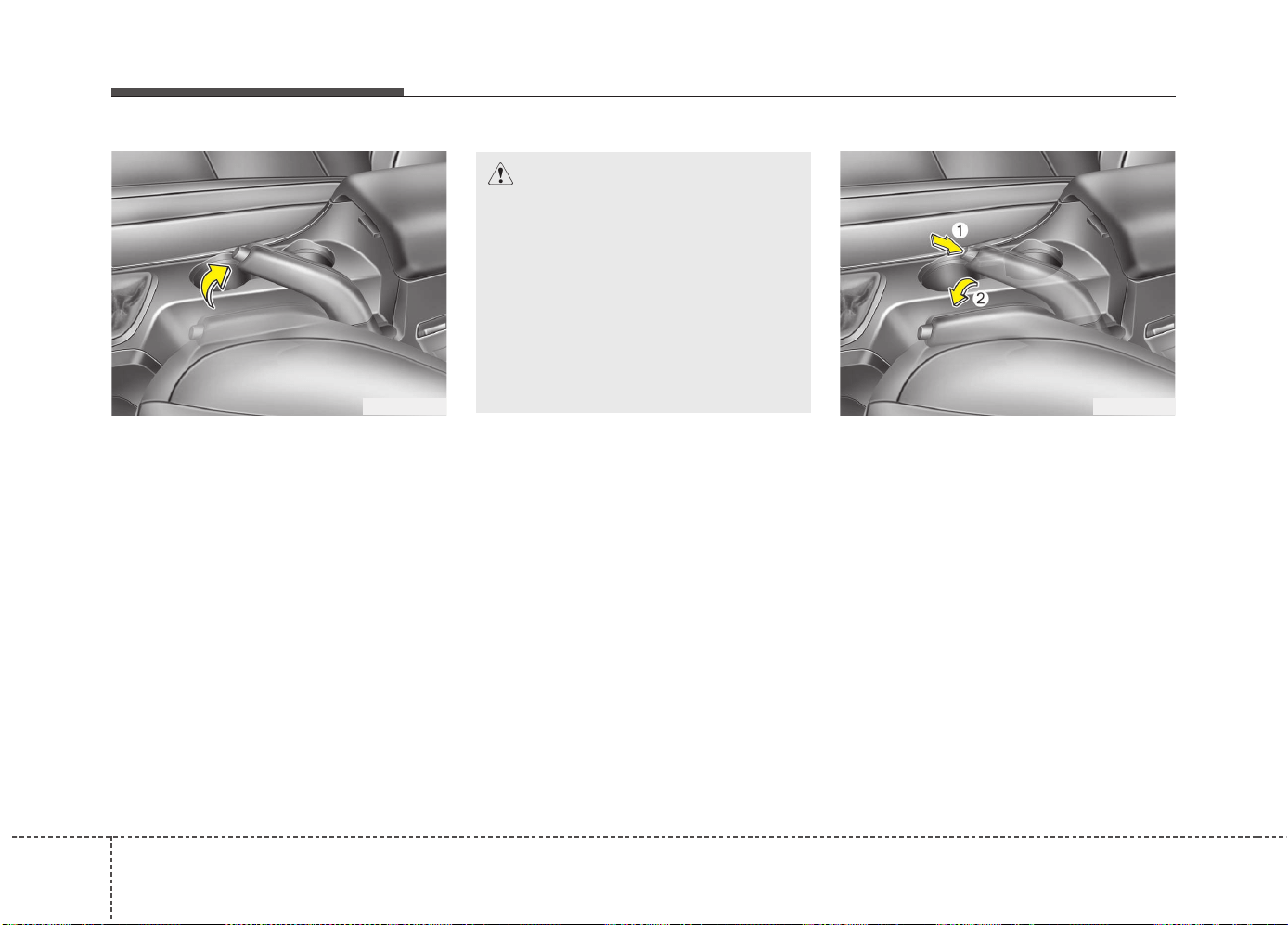
Driving your vehicle
425
Parking brake - Hand type
Applying the parking brake
To engage the parking brake, first apply
the foot brake and then without pressing
the release button in, pull the parking
brake lever up as far as possible. In addi-
tion it is recommended that when parking
the vehicle on a gradient, the shift lever
should be positioned in the appropriate
low gear for manual transaxle vehicles or
in the P (Park) position for automatic
transaxle vehicles.
Releasing the parking brake
To release the parking brake, first apply
the foot brake and pull up the parking
brake lever slightly. Secondly press the
release button (1) and lower the parking
brake lever (2) while pressing the button.
OJD052011OJD052010
CAUTION
• Driving with the parking brake
applied will cause excessive
brake pad (or lining) and brake
rotor wear.
• Do not operate the parking brake
while the vehicle is moving
except in an emergency situation.
It could damage the vehicle sys-
tem and make endanger driving
safety.
543
Driving your vehicle
Check the brake warning light by turning
the ignition switch ON (do not start the
engine). This light will illuminate when the
parking brake is applied with the ignition
switch in the START or ON position.
Before driving, be sure the parking brake
is fully released and the brake warning
light is off.
If the brake warning light remains on
after the parking brake is released while
the engine is running, there may be a
malfunction in the brake system.
Immediate attention is necessary.
If at all possible, cease driving the vehi-
cle immediately. If that is not possible,
use extreme caution while operating the
vehicle and only continue to drive the
vehicle until you can reach a safe loca-
tion or repair shop.
WARNING
• To prevent unintentional move-
ment when stopped and leaving
the vehicle, do not use the shift
lever instead of the parking
brake. Set the parking brake AND
make sure the shift lever is
securely positioned in 1st (First)
gear or R (Reverse) for manual
transaxle equipped vehicles and
in P (Park) for automatic transaxle
equipped vehicles.
• Never allow anyone who is unfa-
miliar with the vehicle to touch
the parking brake. If the parking
brake is released unintentionally,
serious injury may occur.
• All vehicles should always have
the parking brake fully engaged
when parking to avoid inadver-
tent movement of the vehicle
which can injure occupants or
pedestrians.
WK-23
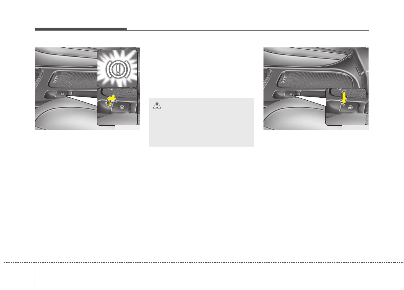
Driving your vehicle
445
Electric parking brake (EPB)
(if equipped)
Applying the parking brake
To apply the EPB (electric parking
brake):
Pull up the EPB switch.
Make sure the warning light comes on.
✽✽
NOTICE
On a steep incline or when pulling a
trailer if the vehicle does not stand still,
do as follows:
1. Apply the EPB.
2. Pull up the EPB switch for more than
3 seconds.
Releasing the parking brake
To release the EPB (electric parking
brake), press the EPB switch in the fol-
lowing condition:
• Have the ignition switch or engine
start/stop button in the ON position.
• Depress the brake pedal.
Make sure the brake warning light goes
off.
OJD052012
CAUTION
Do not operate the parking brake
while the vehicle is moving except
in an emergency situation. It could
damage the vehicle system and
endanger driving safety.
OJD052013
545
Driving your vehicle
To release EPB (electric parking brake)
automatically:
• Manual transaxle vehicle
1. Start the engine.
2. Fasten the driver's seat belt.
3. Close the driver's door, engine hood
and tailgate.
4. Depress the clutch pedal with the
gear engaged.
5. Depress the accelerator pedal while
releasing the clutch pedal.
• Automatic transaxle vehicle
1. Start the engine.
2. Fasten the driver's seat belt.
3. Close the driver's door, engine hood
and tailgate.
4. Depress the accelerator pedal while
the shift lever is in R (Rear), D (Drive).
• Shift lever in P (Park)
With the engine running depress the
brake pedal and shift out of P (Park) to
R (Rear) or D (Drive).
• Shift lever in N (Neutral)
With the engine running depress the
brake pedal and shift out of N (Neutral)
to R (Rear) or D (Drive).
Make sure the brake warning light goes
off.
✽✽
NOTICE
• For your safety, you can engage the
EPB even though the ignition switch or
engine stop/start button is in the OFF
position, but you cannot release it.
• For your safety, depress the brake
pedal and release the parking brake
manually with the EPB switch when
you drive downhill or when backing up
the vehicle.
✽
✽
NOTICE - Manual transaxle
A vehicle towing a trailer on a hill or on
an incline may slightly roll backwards
when starting the vehicle. To prevent the
situation follow the below instructions.
1. Depress the clutch pedal and select a
gear.
2. Keep pulling up the EPB switch.
3. Depress the accelerator pedal and
slowly release the clutch pedal.
4. If the vehicle starts off with enough
driving power release the EPB switch.
Do not follow the above procedure when
driving on a flat level ground. The vehi-
cle may suddenly move forward.
CAUTION
• If the parking brake warning light
is still on even though the EPB
has been released, we recom-
mend that the system be checked
by an authorized Kia dealer.
• Do not drive your vehicle with the
EPB applied. It may cause exces-
sive brake pad and brake rotor
wear.
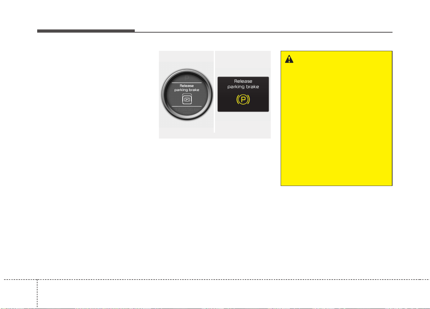
Driving your vehicle
465
EPB (electric parking brake) may be
automatically applied when:
• The EPB is overheated
• Requested by other systems
• If you try to drive off depressing the
accelerator pedal with the EPB applied,
but doesn't release automatically, a
warning will sound and a message will
appear.
• If the driver's seat belt is not fastened
and any door, the engine hood or tail-
gate is opened, a warning will sound
and a message will appear.
• If there is a problem with the vehicle, a
warning may sound and a message
may appear.
If the above situation occurs, depress the
brake pedal and release EPB by pressing
the EPB switch.
WARNING
• To prevent unintentional move-
ment when stopped and leaving
the vehicle, do not use the shift
lever in place of the parking
brake. Set the parking brake and
make sure the shift lever is
securely positioned in P (Park).
• Never allow anyone who is unfa-
miliar with the vehicle to touch
the parking brake. If the parking
brake is released unintentionally,
serious injury may occur.
• All vehicles should always have
the parking brake fully engaged
when parking to avoid inadvertent
movement of the car which can
injure occupants or pedestrians.
■ Normal vision
■ Supervision
OJD052035/OJD045195L
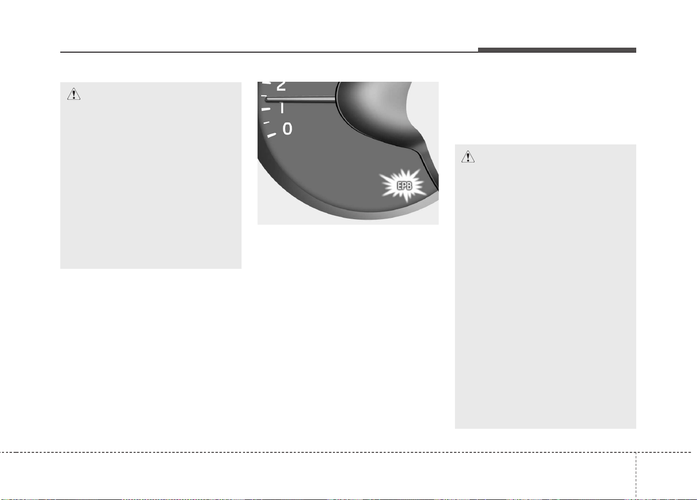
547
Driving your vehicle
EPB malfunction indicator
(if equipped)
This warning light illuminates if the
engine start/stop button is changed to
the ON position and goes off in approxi-
mately 3 seconds if the system is opera-
tion normally.
If the EPB malfunction indicator remains
on, comes on while driving, or does not
come on when the ignition switch or the
engine start/stop button is changed to
the ON position, this indicates that the
EPB may have malfunctioned.
If this occurs, we recommend that the
system be checked by an authorized Kia
dealer.
The EPB malfunction indicator may illu-
minate when the ESC indicator comes
on to indicate that the ESC is not working
properly, but it does not indicate a mal-
function of the EPB.
CAUTION
• A click sound may be heard while
operating or releasing the EPB,
but these conditions are normal
and indicate that the EPB is func-
tioning properly.
• When leaving your keys with a
parking lot attendant or valet,
make sure to inform him/her how
to operate the EPB.
• The EPB may malfunction if you
drive with the EPB applied.
• When you automatically release
EPB by depressing the accelera-
tor pedal, depress it slowly.
OJD052014
CAUTION
• The EPB warning light may illumi-
nate if the EPB switch operates
abnormally. Shut the engine off
and turn it on again after a few
minutes. The warning light will go
off and the EPB switch will oper-
ate normally. However, if the EPB
warning light is still on, we recom-
mend that the system be checked
by an authorized Kia dealer.
• If the parking brake warning light
does not illuminate or blinks even
though the EPB switch was pulled
up, the EPB is not applied.
• If the parking brake warning light
blinks when the EPB warning light
is on, press the switch, then pull it
up. Once more press it back to its
original position and pull it back
up. If the EPB warning does not
go off, we recommend that the
system be checked by an author-
ized Kia dealer.
Driving your vehicle
485
Emergency braking
If there is a problem with the brake pedal
while driving, emergency braking is pos-
sible by pulling up and holding the EPB
switch. Braking is possible only while you
are holding the EPB switch.
✽✽
NOTICE
During emergency braking by the EPB,
the parking brake warning light will
illuminate to indicate that the system is
operating.
When the EPB (electric parking
brake) does not release
If the EPB does not release normally, we
recommend that you take your vehicle to
an authorized Kia dealer by loading the
vehicle on a flatbed tow truck and have
the system checked.
Anti-lock brake system (ABS)
WARNING
Do not operate the parking brake
while the vehicle is moving except
in an emergency situation.
CAUTION
If you continuously notice a noise or
burning smell when the EPB is used
for emergency braking, we recom-
mend that the system be checked
by an authorized Kia dealer.
WARNING
ABS (or ESC) will not prevent acci-
dents due to improper or danger-
ous driving maneuvers. Even
though vehicle control is improved
during emergency braking, always
maintain a safe distance between
you and objects ahead. Vehicle
speeds should always be reduced
during extreme road conditions.
The braking distance for vehicle
equipped with an anti-lock braking
system (or Electronic Stability
Control) may be longer than for
those without it in the following
road conditions.
During these conditions the vehicle
should be driven at reduced
speeds:
• Rough, gravel or snow-covered
roads.
• With tire chains installed.
• On roads where the road surface
is pitted or has different surface
height.
(Continued)

549
Driving your vehicle
The ABS continuously senses the speed
of the wheels. If the wheels are going to
lock, the ABS system repeatedly modu-
lates the hydraulic brake pressure to the
wheels.
When you apply your brakes under con-
ditions which may lock the wheels, you
may hear a “tik-tik’’ sound from the
brakes, or feel a corresponding sensation
in the brake pedal. This is normal and it
means your ABS is active.
In order to obtain the maximum benefit
from your ABS in an emergency situa-
tion, do not attempt to modulate your
brake pressure and do not try to pump
your brakes. Press your brake pedal as
hard as possible or as hard as the situa-
tion warrants and allow the ABS to con-
trol the force being delivered to the
brakes.
✽✽
NOTICE
A click sound may be heard in the
engine compartment when the vehicle
begins to move after the engine is start-
ed. These conditions are normal and
indicate that the anti-lock brake system
is functioning properly.
• Even with the anti-lock brake system,
your vehicle still requires sufficient
stopping distance. Always maintain a
safe distance from the vehicle in front
of you.
• Always slow down when cornering.
The anti-lock brake system cannot pre-
vent accidents resulting from exces-
sive speeds.
• On loose or uneven road surfaces,
operation of the anti-lock brake system
may result in a longer stopping dis-
tance than for vehicles equipped with a
conventional brake system.
(Continued)
The safety features of an ABS (or
ESC) equipped vehicle should not
be tested by high speed driving or
cornering. This could endanger the
safety of yourself or others.
Driving your vehicle
505
✽✽
NOTICE
When you jump start your vehicle
because of a drained battery, the engine
may not run as smoothly and the ABS
warning light may turn on at the same
time. This happens because of the low
battery voltage. It does not mean your
ABS is malfunctioning.
• Do not pump your brakes!
• Have the battery recharged before
driving the vehicle.
CAUTION
• If the ABS warning light is on and
stays on, you may have a problem
with the ABS. In this case, howev-
er, your regular brakes will work
normally.
• The ABS warning light will stay on
for approximately 3 seconds after
the ignition switch is ON. During
that time, the ABS will go through
self-diagnosis and the light will go
off if everything is normal. If the
light stays on, you may have a
problem with your ABS.We recom-
mend that you contact an author-
ized Kia dealer.
CAUTION
• When you drive on a road having
poor traction, such as an icy road,
and operate your brakes continu-
ously, the ABS will be active con-
tinuously and the ABS warning
light may illuminate. Pull your
vehicle over to a safe place and
stop the engine.
• Restart the engine. If the ABS
warning light is off, then your ABS
system is normal. Otherwise, you
may have a problem with the ABS.
We recommend that you contact
an authorized Kia dealer.
W-78
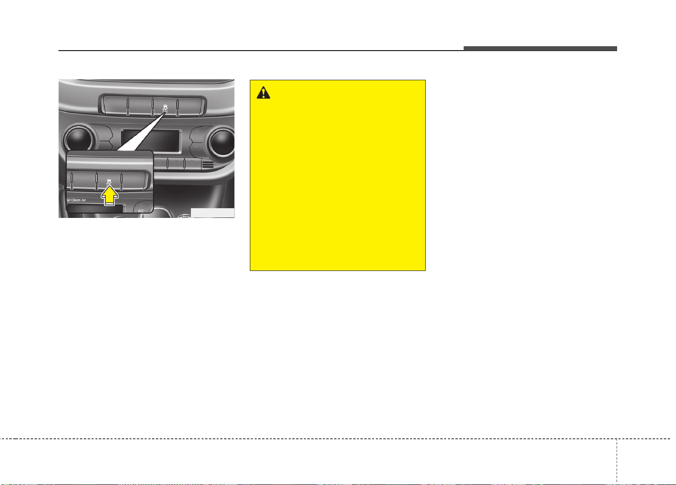
551
Driving your vehicle
Electronic stability control (ESC)
(if equipped)
The Electronic Stability Control (ESC)
system is designed to stabilize the vehi-
cle during cornering maneuvers. ESC
checks where you are steering and
where the vehicle is actually going. ESC
applies the brakes at individual wheels
and intervenes with engine management
system to stabilize the vehicle.
The Electronic stability control (ESC)
system is an electronic system designed
to help the driver maintain vehicle control
under adverse conditions. It is not a
substitute for safe driving practices.
Factors including speed, road conditions
and driver steering input can all affect
whether ESC will be effective in
preventing a loss of control. It is still your
responsibility to drive and corner at
reasonable speeds and to leave a
sufficient margin of safety.
When you apply your brakes under con-
ditions which may lock the wheels, you
may hear a “tik-tik’’ sound from the
brakes, or feel a corresponding sensation
in the brake pedal. This is normal and it
means your ESC is active.
✽✽
NOTICE
A click sound may be heard in the
engine compartment when the vehicle
begins to move after the engine is start-
ed. These conditions are normal and
indicate that the Electronic stability
control (ESC) System is functioning
properly.
WARNING
Never drive too fast for the road
conditions or too quickly when cor-
nering. Electronic stability control
(ESC) will not prevent accidents.
Excessive speed in turns, abrupt
maneuvers and hydroplaning on
wet surfaces can still result in seri-
ous accidents. Only a safe and
attentive driver can prevent acci-
dents by avoiding maneuvers that
cause the vehicle to lose traction.
Even with ESC installed, always fol-
low all the normal precautions for
driving - including driving at safe
speeds for the conditions.
OJD052009
Driving your vehicle
525
ESC operation
ESC ON condition
• When the ignition is turned
ON, ESC and ESC OFF indi-
cator lights illuminate for
approximately 3 seconds,
then ESC is turned on.
• Press the ESC OFF button
for at least half a second after
turning the ignition ON to turn
ESC off. (ESC OFF indicator
will illuminate). To turn the
ESC on, press the ESC OFF
button (ESC OFF indicator
light will go off).
• When starting the engine,
you may hear a slight ticking
sound. This is the ESC per-
forming an automatic system
self-check and does not indi-
cate a problem.
When operating
When the ESC is in operation,
ESC indicator light blinks.
• When the Electronic Stability
Control is operating properly,
you can feel a slight pulsation
in the vehicle. This is only the
effect of brake control and indi-
cates nothing unusual.
• When moving out of the mud
or slippery road, the engine
rpm (revolution per minute)
may not increase even if you
press the accelerator pedal
deeply. This is to maintain the
stability and traction of the
vehicle and does not indicate
a problem.
ESC operation off
ESC OFF state
This car has 2 kinds of ESC off
states.
If the engine stops when ESC is
off, ESC remains off. Upon
restarting the engine, the ESC
will automatically turn on again.
-
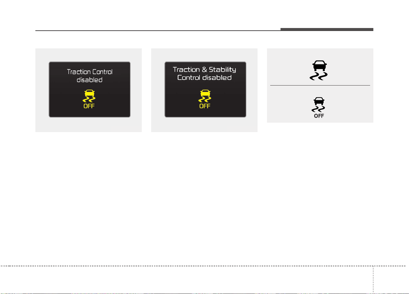
553
Driving your vehicle
• ESC off state 1
To cancel ESC operation, press the ESC
OFF button shortly (ESC OFF indicator
light illuminates). At this state, the engine
control function does not operate. It
means the traction control function does
not operate. Brake control function only
operates.
• ESC off state 2
To cancel ESC operation, press the ESC
OFF button for more than 3 seconds.
ESC OFF indicator light illuminates and
ESC OFF warning chime will sound. At
this state, the engine control function and
brake control function do not operate. It
means the car stability control function
does not operate any more.
Indicator light
When ignition switch is turned to ON, the
indicator light illuminates, then goes off if
the ESC system is operating normally.
The ESC indicator light blinks whenever
ESC is operating or illuminates when
ESC fails to operate.
ESC OFF indicator light comes on when
the ESC is turned off with the button.
■ ESC indicator light
■ ESC OFF indicator light
OUM054161L OUM054163L
Driving your vehicle
545
ESC OFF usage
When driving
• ESC should be turned on for daily driv-
ing whenever possible.
• To turn ESC off while driving, press the
ESC OFF button while driving on a flat
road surface.
✽✽
NOTICE
• When operating the vehicle on a
dynamometer, ensure that the ESC is
turned off by pressing the ESC OFF
button for more than 3 seconds (ESC
OFF light illuminated). If the ESC is
left on, it may prevent the vehicle
speed from increasing, and result in
false diagnosis.
• Turning the ESC off does not affect
ABS or brake system operation.
Vehicle stability management
(VSM) (if equipped)
This system provides further enhance-
ments to vehicle stability and steering
responses when a vehicle is driving on a
slippery road or a vehicle detected
changes in coefficient of friction between
right wheels and left wheels when brak-
ing.
VSM operation
When the VSM is operating:
• ESC (Electronic Stability Control) ( )
light will blink.
• The steering wheel may be controlled.
When the vehicle stability management
is operating properly, you can feel a slight
pulsation in the vehicle. This is only the
effect of brake control and indicates noth-
ing unusual.
The VSM does not operate when:
• Driving on bank road such as gradient
or incline
• Driving rearward
• ESC OFF indicator light ( ) remains
on the instrument cluster
• EPS (Electronic Power Steering) indi-
cator light remains on the instrument
cluster
CAUTION
Driving with varying tire or wheel
sizes may cause the ESC system to
malfunction. When replacing tires,
make sure they are the same size as
your original tires.
WARNING
The Electronic Stability Control sys-
tem is only a driving aid; use pre-
cautions for safe driving by slowing
down on curved, snowy, or icy
roads. Drive slowly and don’t
attempt to accelerate whenever the
ESC indicator light is blinking, or
when the road surface is slippery.
WARNING
Never press the ESC OFF button
while ESC is operating (ESC indica-
tor light blinks).
If ESC is turned off while ESC is
operating, the vehicle may slip out
of control.
555
Driving your vehicle
VSM operation off
If you press the ESC OFF button to turn
off the ESC, the VSM will also cancel and
the ESC OFF indicator light ( ) illumi-
nates.
To turn on the VSM, press the button again.
The ESC OFF indicator light goes out.
Malfunction indicator
The VSM can be deactivated even if you
don’t cancel the VSM operation by press-
ing the ESC OFF button. It indicates that
a malfunction has been detected some-
where in the EPS (Electronic Power
Steering) system or VSM system. If the
ESC indicator light ( ) or EPS warning
light remains on, we recommend that the
system be checked by an authorized Kia
dealer.
✽✽
NOTICE
• The VSM is designed to function
above approximately 15 km/h (9 mph)
on curves.
• The VSM is designed to function
above approximately 30 km/h (18
mph) when a vehicle is braking on a
split-mu road. The split-mu road is
made of surfaces which have different
friction forces.
Hill-start assist control (HAC)
(if equipped)
A vehicle has the tendency to slip back
on a steep hill when it starts to go after
stopping. The Hill-start Assist Control
(HAC) prevents the vehicle from slipping
back by operating the brakes automati-
cally for about 1~2 seconds. The brakes
are released when the accelerator pedal
is depressed or after about 1~2 seconds.
✽✽
NOTICE
• The HAC does not operate when the
transaxle shift lever is in the P (Park)
or N (Neutral) position.
• The HAC activates even though the
ESC is off but it does not activate
when the ESC has malfunctioned.
WARNING
The HAC is activated only for about
1~2 seconds, so when the vehicle
is starting off always depress the
accelerator pedal.
WARNING
• The Vehicle Stability Management
system is not a substitute for
safe driving practices but a sup-
plementary function only. It is the
responsibility of the driver to
always check the speed and the
distance to the vehicle ahead.
Always hold the steering wheel
firmly while driving.
• Your vehicle is designed to acti-
vate according to the driver’s
intention, even with the VSM
installed. Always follow all the
normal precautions for driving at
safe speeds for the conditions –
including driving in inclement
weather and on a slippery road.
• Driving with varying tire or wheel
sizes may cause the VSM system
to malfunction. When replacing
tires, make sure they are the
same size as your original tires.
Driving your vehicle
565
Emergency Stop Signal (ESS)
The Emergency Stop Signal system
alerts the driver behind by blinking the
stop light when the vehicle is braked rap-
idly and severely.
The system is activated when:
• The vehicle suddenly stops (vehicle
speed is over 55km/h and the vehicle
deceleration at greater than 7 m/s
2
)
• The ABS is activating
When the vehicle speed is under 40 km/h
and the ABS deactivates or the sudden
stop situation is over, the stop light blink-
ing will stop. Instead, the hazard warning
flasher will turn on automatically.
The hazard warning flasher will turn off
when vehicle speed is over 10km/h after
the vehicle has stopped. Also, it will turn
off when the vehicle is driven at low
speed for some time. You can turn it off
manually by pushing the hazard warning
flasher switch.
Good braking practices
• Check to be sure the parking brake is
not engaged and that the parking
brake indicator light is out before driv-
ing away.
• Driving through water may get the
brakes wet. They can also get wet
when the vehicle is washed. Wet
brakes can be dangerous! Your vehicle
will not stop as quickly if the brakes are
wet. Wet brakes may cause the vehicle
to pull to one side.
To dry the brakes, apply the brakes
lightly until the braking action returns to
normal, taking care to keep the vehicle
under control at all times. If the braking
action does not return to normal, stop
as soon as it is safe to do so and we
recommend that you call an authorized
Kia dealer.
• Do not coast down hills with the vehicle
out of gear. This is extremely haz-
ardous. Keep the vehicle in gear at all
times, use the brakes to slow down,
then shift to a lower gear so that
engine braking will help you maintain a
safe speed.
WARNING
• Whenever you leave or park your
vehicle, always set the parking
brake as far as possible and fully
engage the vehicle's transaxle
into the P (Park) position. If the
parking brake is not fully
engaged, the vehicle may move
inadvertently and injure yourself
and others.
• All vehicles should always have
the parking brake fully engaged
when parking to avoid inadver-
tent movement of the vehicle
which can injure occupants or
pedestrians.
CAUTION
The Emergency Stop Signal (ESS)
system will not work if the hazard
warning flasher is already on.

557
Driving your vehicle
• Do not "ride" the brake pedal. Resting
your foot on the brake pedal while driv-
ing can be dangerous because it can
result in the brakes overheating and
losing their effectiveness. It also
increases the wear of the brake com-
ponents.
• If a tire goes flat while you are driving,
apply the brakes gently and keep the
vehicle pointed straight ahead while
you slow down. When you are moving
slowly enough for it to be safe to do so,
pull off the road and stop in a safe
place.
• If your vehicle is equipped with an
automatic transaxle, do not let your
vehicle creep forward. To avoid creep-
ing forward, keep your foot firmly on
the brake pedal when the vehicle is
stopped.
• Be cautious when parking on a hill.
Firmly engage the parking brake and
place the shift lever in P (automatic
transaxle) or in first or reverse gear
(manual transaxle). If your vehicle is
facing downhill, turn the front wheels
into the curb to help keep the vehicle
from rolling. If your vehicle is facing
uphill, turn the front wheels away from
the curb to help keep the vehicle from
rolling. If there is no curb or if it is
required by other conditions to keep the
vehicle from rolling, block the wheels.
• Under some conditions your parking
brake can freeze in the engaged posi-
tion. This is most likely to happen when
there is an accumulation of snow or ice
around or near the rear brakes or if the
brakes are wet. If there is a risk that the
parking brake may freeze, apply it only
temporarily while you put the shift
lever in P (automatic transaxle) or in
first or reverse gear (manual transaxle)
and block the rear wheels so the vehi-
cle cannot roll. Then release the park-
ing brake.
• Do not hold the vehicle on the upgrade
with the accelerator pedal. This can
cause the transaxle to overheat.
Always use the brake pedal or parking
brake.
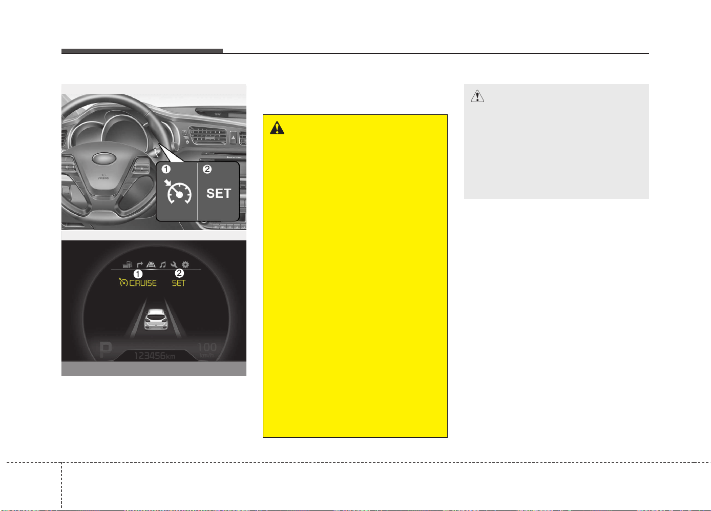
Driving your vehicle
585
1. Cruise indicator
2. Cruise set indicator
The cruise control system allows you to
program the vehicle to maintain a con-
stant speed without pressing the acceler-
ator pedal.
This system is designed to function
above approximately 30 km/h (20 mph).
✽✽
NOTICE
• During normal cruise control opera-
tion, when the SET switch is activated
or reactivated after applying the
brakes, the cruise control will ener-
gize after approximately 3 seconds.
This delay is normal.
• To activate cruise control, depress the
brake pedal at least once after turning
the ignition switch to the ON position
or starting the engine. This is to check
if the brake switch which is important
part to cancel cruise control is in nor-
mal condition.
CRUISE CONTROL SYSTEM (IF EQUIPPED)
WARNING
• If the cruise control is left on,
(cruise indicator light is illuminat-
ed), the cruise control can be
switched on accidentally. Keep
the cruise control system off
when the cruise control is not in
use, to avoid inadvertently set-
ting a speed.
• Use the cruise control system
only when traveling on open
highways in good weather.
• Do not use the cruise control
when it may not be safe to keep
the vehicle at a constant speed,
for instance, driving in heavy or
varying traffic, or on slippery
(rainy, icy or snow-covered) or
winding roads or over 6% up-hill
or down-hill roads.
• Pay particular attention to the
driving conditions whenever
using the cruise control system.
• Be careful when driving downhill
using the cruise control system,
which may increase the vehicle
speed.
CAUTION
During cruise-speed driving of a
manual transaxle vehicle, do not
shift into neutral without depress-
ing the clutch pedal, since the
engine will be overrevved. If this
happens, depress the clutch pedal
or release the cruise control ON-
OFF switch.
OJD052015/OJD055048L
■ Supervision
■ Normal vision
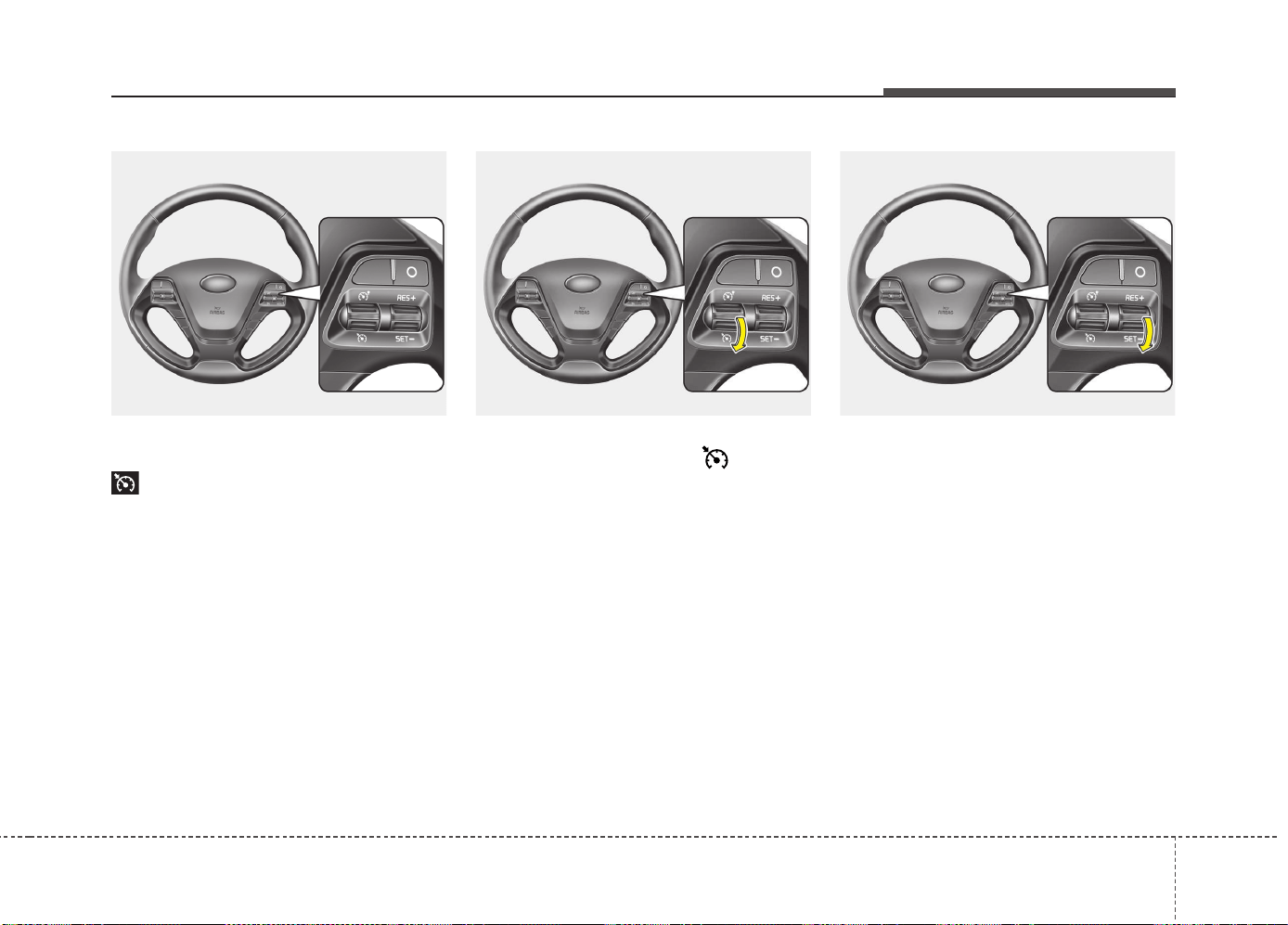
559
Driving your vehicle
Cruise control switch
O: Cancels cruise control operation.
: Turns cruise control system on or
off.
RES+: Resumes or increases cruise
control speed.
SET-: Sets or decreases cruise control
speed.
To set cruise control speed:
1. Move the lever down ( ) on the
steering wheel, to turn the system on.
The cruise indicator light will illumi-
nate.
2. Accelerate to the desired speed, which
must be more than 30 km/h (20 mph).
✽✽
NOTICE - Manual transaxle
For manual transaxle vehicles, you
should depress the brake pedal at least
once to set the cruise control after start-
ing the engine.
3. Move the lever down (to SET-), and
release it at the desired speed. The
cruise set indicator light will illuminate.
Release the accelerator pedal at the
same time. The desired speed will
automatically be maintained.
On a steep grade, the vehicle may slow
down or speed up slightly while going
downhill.
OJD053016 OJD053017 OJD053018
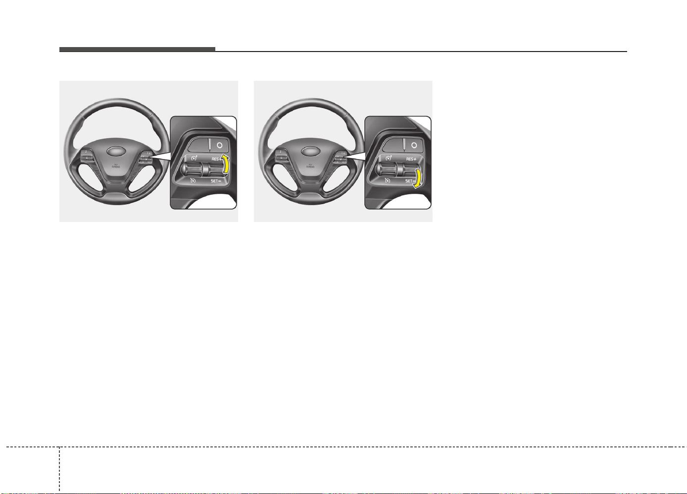
Driving your vehicle
605
To increase cruise control set
speed:
Follow either of these procedures:
• Move the lever up (to RES+) and hold
it. Your vehicle will accelerate. Release
the lever at the speed you want.
• Move the lever up (to RES+) and
release it immediately. The cruising
speed will increase by 2 km/h (1 mph)
each time you move the lever up (to
RES+) in this manner.
To decrease the cruising speed:
Follow either of these procedures:
• Move the lever down (to SET-) and
hold it. Your vehicle will gradually slow
down. Release the lever at the speed
you want to maintain.
• Move the lever down (to SET-) and
release it immediately. The cruising
speed will decrease by 2 km/h (1 mph)
each time you move the lever down (to
SET-) in this manner.
To temporarily accelerate with the
cruise control on:
If you want to speed up temporarily when
the cruise control is on, depress the
accelerator pedal. Increased speed will
not interfere with cruise control operation
or change the set speed.
To return to the set speed, take your foot
off the accelerator pedal.
OJD053019 OJD053018
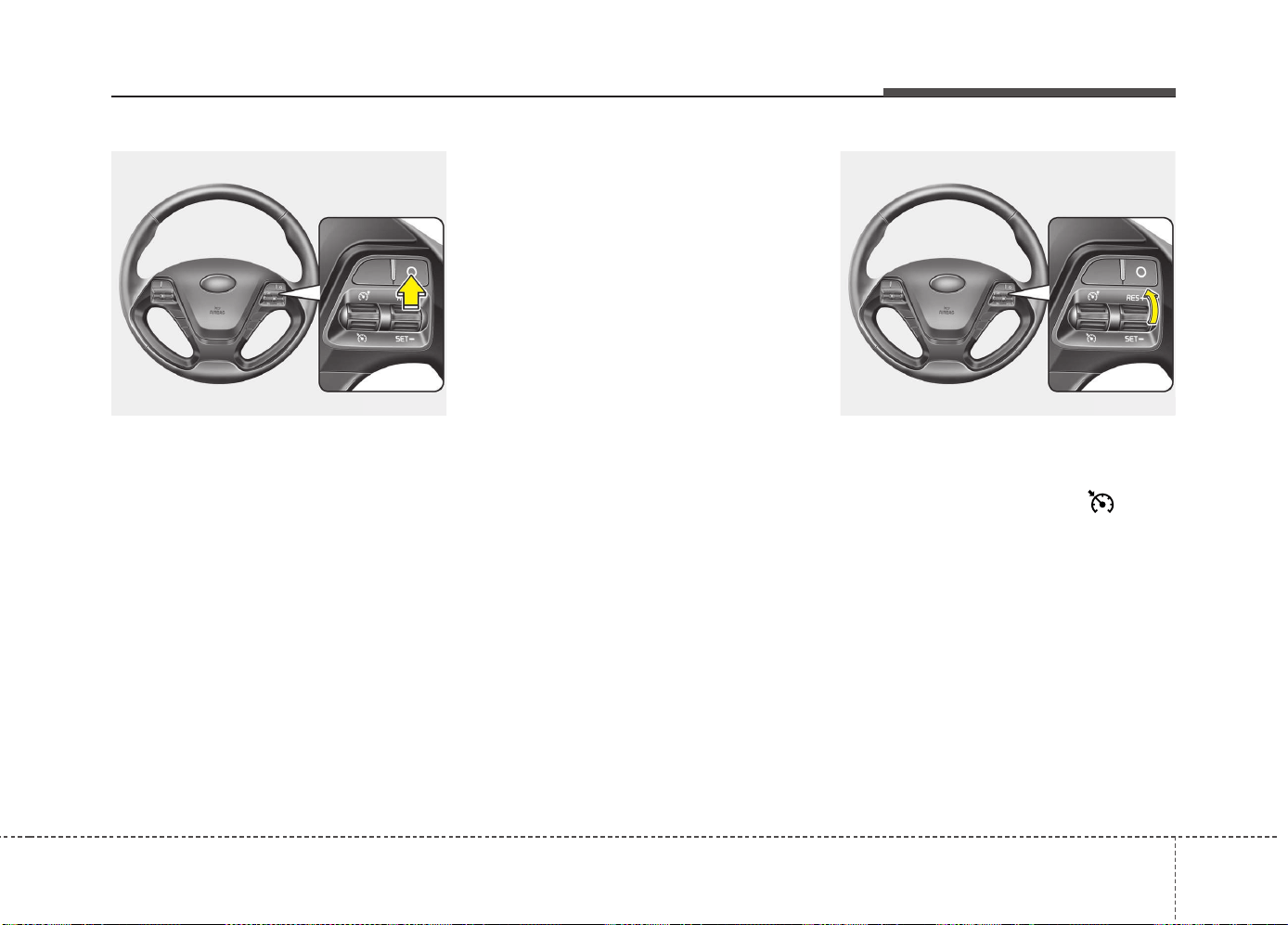
561
Driving your vehicle
To cancel cruise control, do one
of the following:
• Depress the brake pedal.
• Depress the clutch pedal if equipped
with a manual transaxle.
• Shift into N (Neutral) if equipped with
an automatic transaxle.
• Press the O (Cancel) button located on
the steering wheel.
• Decrease the vehicle speed lower than
the memory speed by 20 km/h (12
mph).
• Decrease the vehicle speed to less
than approximately 30 km/h (20 mph).
Each of these actions will cancel cruise
control operation (the
cruise set
indicator
light will go off), but it will not turn the
system off. If you wish to resume cruise
control operation, move up the lever (to
RES+) located on your steering wheel.
You will return to your previously preset
speed.
To resume cruising speed at
more than approximately 30 km/h
(20 mph):
If any method other than the button
was used to cancel cruising speed and
the system is still activated, the most
recent set speed will automatically
resume when the +RES switch is
pushed.
It will not resume, however, if the vehicle
speed has dropped below approximately
30 km/h (20 mph).
OJD053020 OJD053019

Driving your vehicle
625
To turn cruise control off, do one
of the following:
• Move the lever down ( ).
• Move the lever up ( ). (If you move
the lever up, the speed limit system will
turn on)
• Turn the ignition off.
Both of these actions cancel cruise con-
trol operation. If you want to resume
cruise control operation, repeat the steps
provided in “To set cruise control speed”
on the previous page.
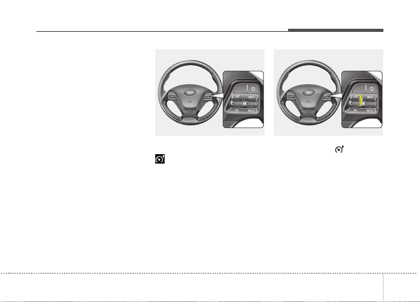
563
Driving your vehicle
You can set the speed limit when you do
not want to drive over a specific speed.
If you drive over the preset speed limit,
the warning system operates (set speed
limit will blink and chime will sound) until
the vehicle speed returns within the
speed limit.
✽✽
NOTICE
While speed limit control is in opera-
tion, the cruise control system cannot be
activated.
Speed limit control switch
O: Cancels set speed limit.
: Turns speed limit control system on
or off.
RES+: Resumes or increases speed limit
control speed.
SET-: Sets or decreases speed limit con-
trol speed.
To set speed limit :
1. Move the lever up ( ) on the steer-
ing wheel, to turn the system on.
SPEED LIMIT CONTROL SYSTEM (IF EQUIPPED)
OJD053021OJD053016
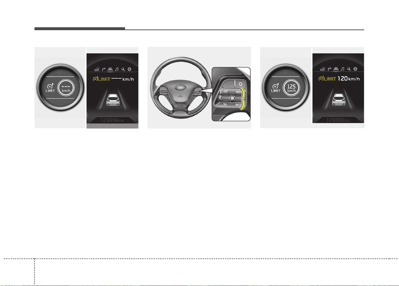
Driving your vehicle
645
The speed limit indicator light will illumi-
nate.
2. Move the lever down (to SET-).
3. Move the lever up (to RES+) or down
(to SET-), and release it at the desired
speed. Move the lever up (to RES+) or
down (to SET-) and hold it. The speed
will increase or decrease by 5 km/h (3
mph).
Move the lever up (to RES+) or down
(SET-) and release it immediately. The
speed will increase or decrease by 1
km/h.
The set speed limit will display on the
instrument cluster.
The set speed limit will be displayed.
OJD052031/OJD055034L
■ Normal vision
■ Supervision
OJD053022
■ Normal vision
■ Supervision
OJD052032/OJD055044L
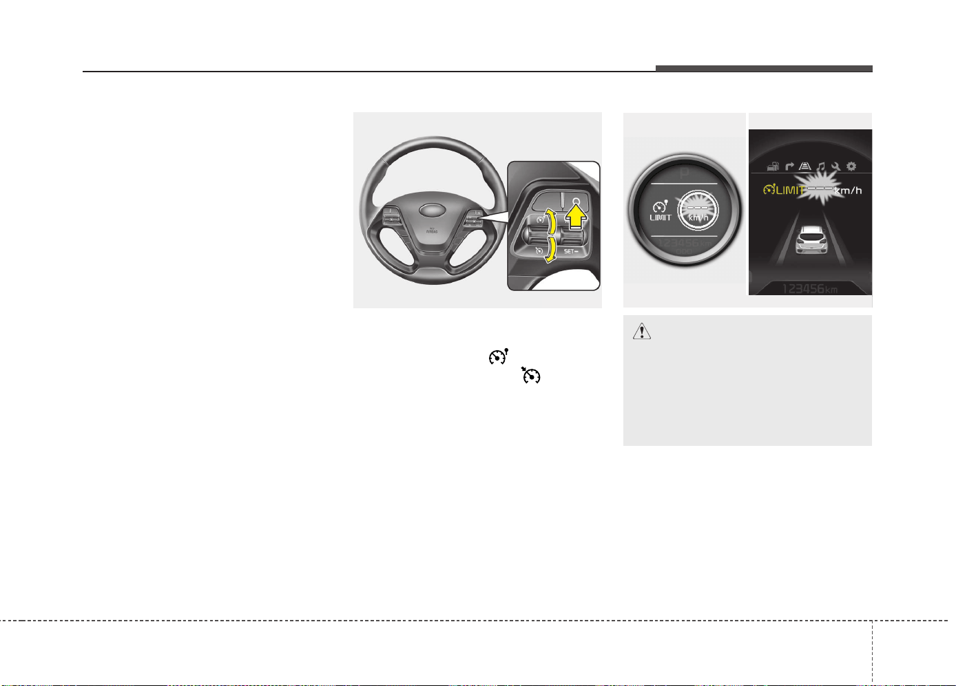
565
Driving your vehicle
To drive over the preset speed limit you
must depress hard on the accelerator
pedal (more than approximately 80%)
until the kick down mechanism works
with a clicking noise. Then the set speed
limit will blink and chime will sound until
you return the vehicle speed within the
speed limit.
✽✽
NOTICE
• Depressing the accelerator pedal less
than approximately 50%, the vehicle
will not speed over the preset speed
limit but maintain the vehicle speed
within the speed limit.
• A clicking noise heard from the kick
down mechanism by depressing the
accelerator pedal fully is a normal
condition.
To turn off the speed limit con-
trol, do one of the following:
• Move the lever up ( ).
• Move the lever down ( ). (If you
move the lever down, the cruise sys-
tem will turn on)
• Turn the ignition off.
If you press the O (CANCEL) button
once, the set speed limit will cancel, but
it will not turn the system off. If you wish
to reset the speed limit, move the lever
up (to RES+) or down (to SET-) on your
steering wheel to your desired speed.
CAUTION
The “---” indicator will blink if there
is a problem with speed limit con-
trol system.
If this occurs, we recommend that
the system be checked by an
authorized Kia dealer.
OJD053023
■ Normal vision
■ Supervision
OJD052033/OJD055046L
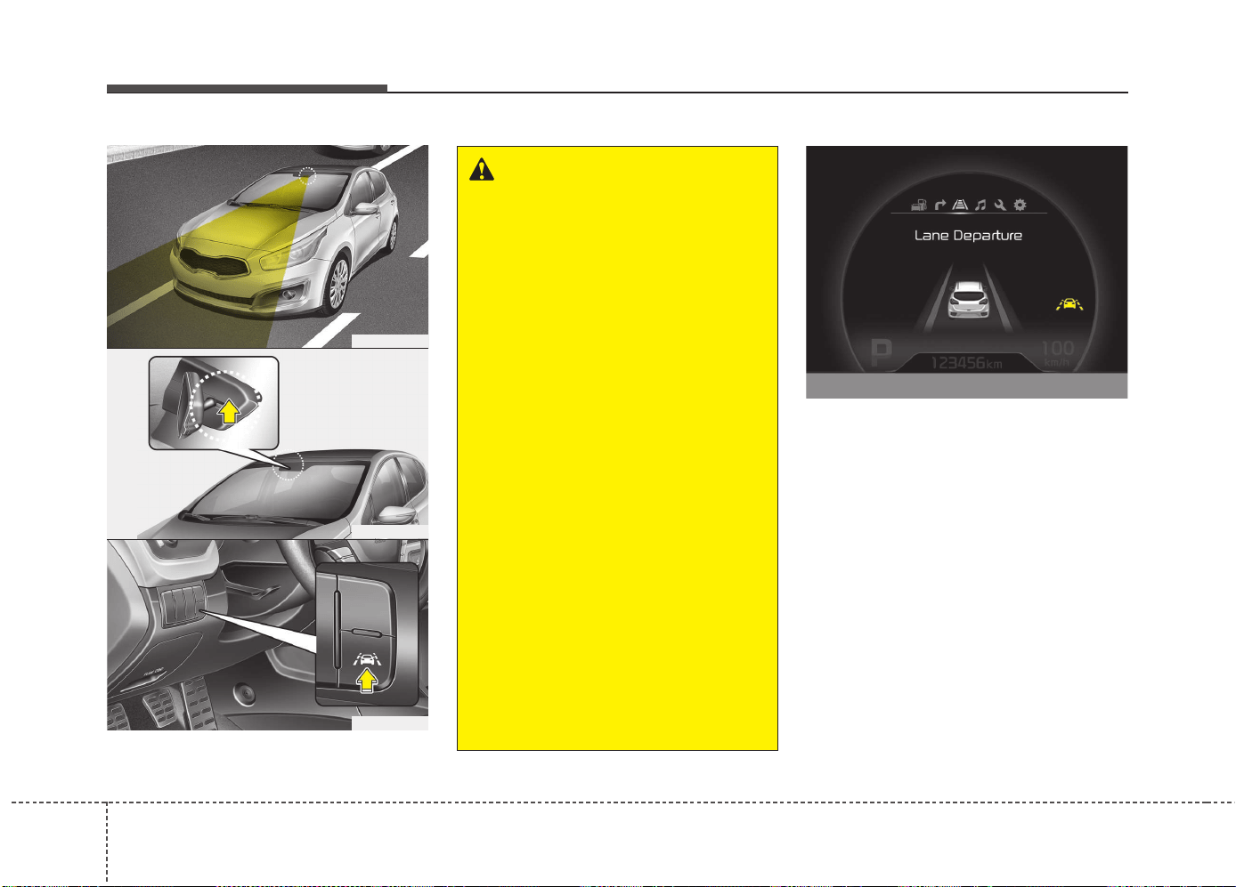
Driving your vehicle
665
This system detects the lane with the
sensor at the front windshield and warns
you when your vehicle leaves the lane.
To operate the LDWS, press the switch
with the ignition in the ON position. The
indicator illuminates on the cluster. To
cancel the LDWS, press the switch
again.
LANE DEPARTURE WARNING SYSTEM (LDWS) (IF EQUIPPED)
WARNING
• The LDWS does not make the vehi-
cle change lanes. It is the driver's
responsibility to always check the
road conditions.
• Do not turn the steering wheel sud-
denly, when the LDWS warns you
that your vehicle is leaving the lane.
• If the sensor can not detect the lane
or if the vehicle speed does not
exceed 60km/h, the LDWS won't
warn you even though the vehicle
leaves the lane.
• If your vehicle has window tint or
other types of coating on the front
windshield, the LDWS may not
work properly.
• Do not let water or any kind of liq-
uid come in contact with the LDWS
sensor.
• Do not remove the LDWS parts and
do not affect the sensor by a strong
impact.
• Do not put objects that reflect light
on the dash board.
• Always check road conditions
because you may not hear the
warning chime because of audio
and external conditions.
OJD052030
OJD052029
OJD045178L
OJD055028
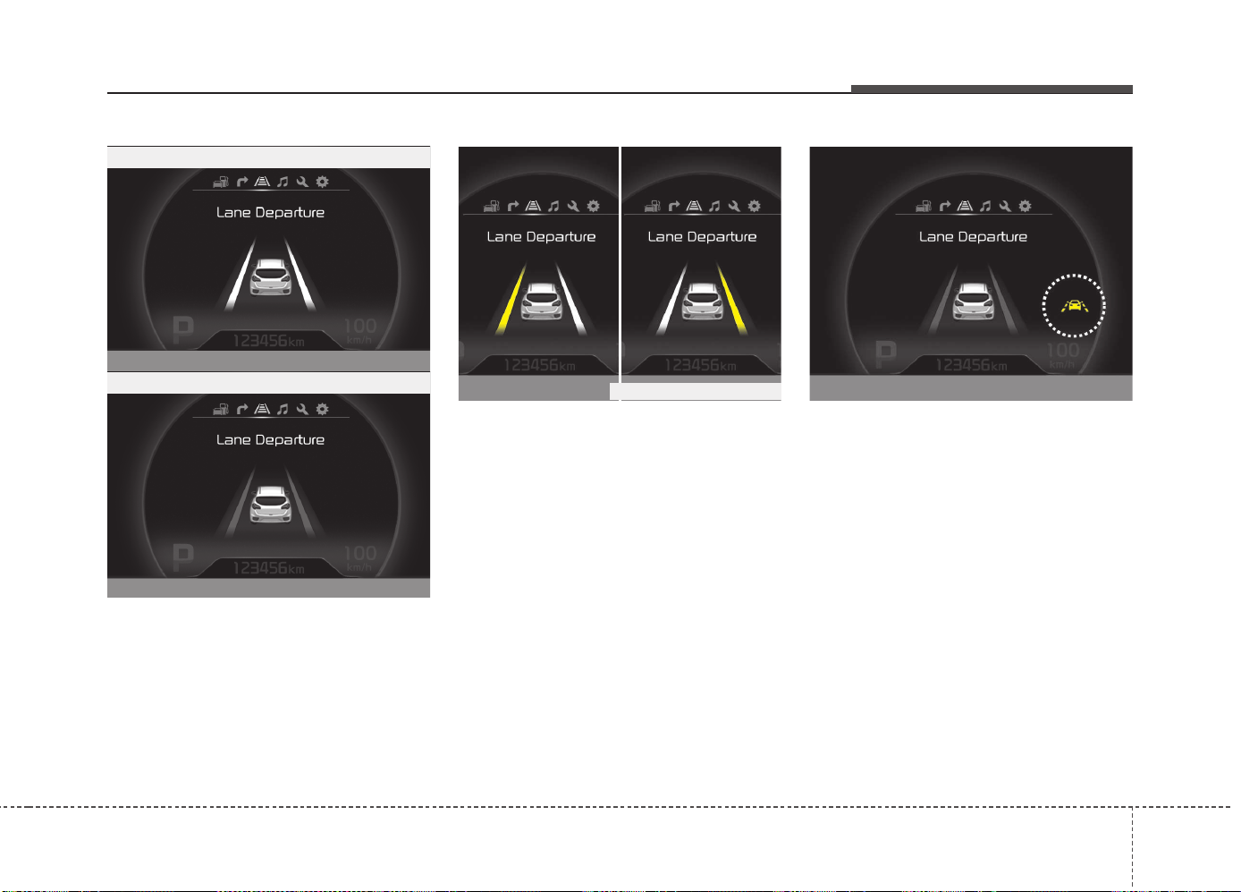
567
Driving your vehicle
If your vehicle leaves the lane when the
LDWS is operating and vehicle speed
exceeds 60km/h, the warning operates
as follows:
1. Visual warning
If you leave the lane, the lane you leave
on the LCD display blinks yellow with 0.8
second of interval.
2. Auditory warning
If you leave the lane, the warning sound
operates with 0.8 second of interval.
If you change the display mode of trip
computer while the LDWS is ON, the
symbol of the LDWS will display like a
picture.
The color of symbol will change depend
on the condition of LDWS system.
- White color : It means the sensor does
not detect the lane line.
- Green color : It means the sensor detects
the lane line.
OJD045180L
OJD045179L
• When the sensor detects the lane line
• When the sensor doesn’t detect the lane line
OJD055057LOJD045181L/OJD045182L
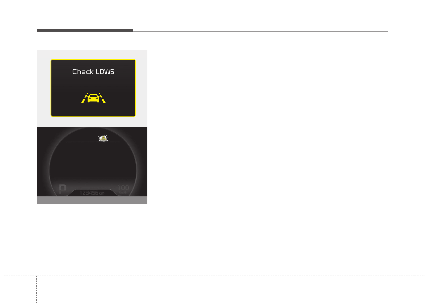
Driving your vehicle
685
Warning indicator
When the LDWS is not working properly,
the warning light will illuminate and the
warning message will come on for a few
second. After the message disappears,
the master warning light will illuminate.
We recommend that the system be
checked by an authorized Kia dealer.
The LDWS does not operate
when:
• The driver turns on the turn signal or
the hazard warning flasher to change
lane.
• Driving on the lane line.
✽✽
NOTICE
To change lane, operate the turn signal
switch, then change the lane.
The LDWS may not warn you even
if the vehicle leaves the lane, or
may warn you even if the vehicle
does not leave the lane when:
• The lane is not visible due to snow, rain,
stain, a puddle or many other things.
• The brightness of the outside changes
suddenly.
• Not turning on the headlight even at
night or in the tunnel.
• Difficult to distinguish the color of the
lane from the road.
• Driving on a steep grade or a curve.
• Light reflects from the water on the
road.
• The lens or windshield is stained with
foreign matter.
• The sensor can not detect the lane
because of fog, heavy rain or heavy
snow.
• The surrounding temperature of the
inside rear view mirror is high due to a
direct ray of light.
• The lane is very wide or narrow.
• The lane line is damaged or indistinct.
• The shadow is on the lane line by a
median strip.
• There is a mark similar to a lane line.
• There is a boundary structure.
• The distance from vehicle ahead is
very short or the vehicle ahead hides
the lane line.
• The vehicle shakes heavily.
• The lane number increases or decreas-
es or the lane lines are crossing com-
plicatedly.
• Putting something on the dashboard.
• Driving with the sun in front of you.
• Driving in areas under construction.
• The lane line is more than two in either
side (Left/Right).
OUM054158L
OJD055174L
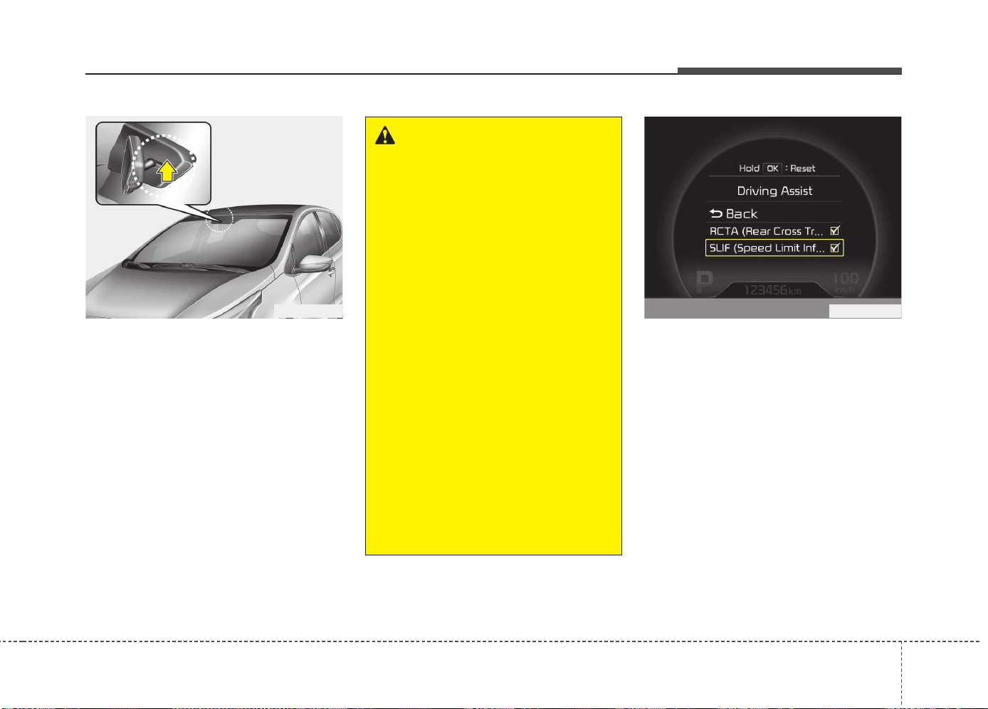
569
Driving your vehicle
The system displays the information of
speed limit and no passing restriction to
the driver in both the instrument cluster
and navigation screen. SLIF detects traf-
fic signs with camera system attached
behind the top of the windscreen.
The SLIF also utilizes the navigation
information to display the speed limit
information.
SLIF activation / deactivation
• SLIF Setting method :
Cluster User Settings → Driving Assist
→ SLIF (Speed Limit Information
Function)
• The information of speed limit and no
passing restriction will appear on the
cluster using a symbol if you have acti-
vated SLIF in User Settings of cluster.
• If SLIF is activated in navigation set-
ting, the information also displayed in
navigation screen.
SPEED LIMIT INFORMATION FUNCTION (SLIF) (IF EQUIPPED)
OJD052029
WARNING
• Speed Limit Information Function
is only an aid and is not always able
to correctly display speed limits
and overtaking restrictions.
• The driver always keeps the
responsibility to not exceed the
maximum allowed speed
• Do not place any accessories,
stickers or tint the windshield near
the rearview mirror.
• The system detects traffic signs
and displays speed limit informa-
tion by a camera therefore, if traffic
signs are hard to detect, the system
may not work properly.
Please refer to "Driver's Attention".
• Do not remove any LDWS parts or
apply impact.
• Do not place objects on the dash-
board that reflects light such as
mirrors, white paper, etc. The sys-
tem may malfunction if the sunlight
is reflected.
• The system is not available in all
countries.
OJD055153L
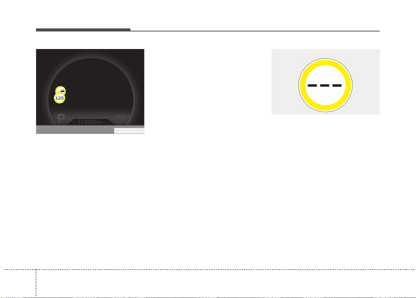
Driving your vehicle
705
Operation
• If a traffic sign that is relevant to your
vehicle is passed, the system displays
the information of the speed limits and
no passing restrictions to the driver.
• When the driver turn on the ignition,
the system displays stored information
of the speed limit before turn off the
ignition.
• Sometimes different speed limits are
displayed for the same road. The infor-
mation displayed depending on the sit-
uation. Because, traffic signs with addi-
tional sign (e.g rainy, arrow...) are also
detected and compared with vehicle
interior data(e.g wiper operation, turn
signal...).
• The system can update the speed limit
information without visible speed limit
signs in the following situations.
- When you change your driving direc-
tion with right or left or U turning.
- When vehicle changes roads. (e.g.
from highway to country road…)
- When you enter or exit into town or
village.
✽✽
NOTICE
If speed limit value has the difference
between cluster and navigation, check
the speed unit setting in navigation.
Display
• If the system doesn’t have a reliable
speed limit information, the following
symbol is displayed in both the instru-
ment cluster and navigation screen.
WUM-203
■ No reliable speed limit information
OJD055173L
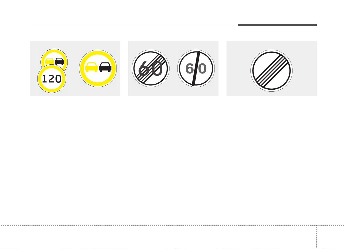
571
Driving your vehicle
• If the system detect no passing sign,
no passing is displayed in both the
instrument cluster and navigation
screen.
• After passing "end of speed limitation“
sign SLIF provides information from
navigation to inform driver of perhaps
afterwards applicable speed limit.
• For some areas on highways in ger-
many there's no speed limit applicable.
In that case SLIF shows "end of limita-
tion" traffic sign as long as you don't
pass another speed limit sign.
WUM-206/WUM-204
■ No passing information
WUM-207/WUM-208
■ End of a speed limit
WUM-205
■ Unlimited speed (only in Germany)
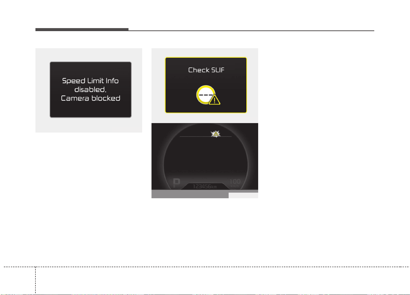
Driving your vehicle
725
Warning message
The message will appear when camera’s
field of view is covered by some objects.
The system stops until the field of view is
normal.
Check the windshield around the camera
view area.
If the system does not work normally
even though camera’s field of view is
cleared, we recommend that the system
be checked by an authorized Kia dealer.
When SLIF is not working properly, the
warning message will come on for a few
second. After the message disappears,
the master warning light will illuminate.
We recommend that the system be
checked by an authorized Kia dealer.
The system may not fully operate and
provide correct information in the follow-
ing situations.
• Traffic signs are positioned on sharp
curve.
• Poorly positioned traffic sign. (eg.
Rotated, shaded by any object, dam-
aged…)
• Concealed traffic signs by other vehicle.
• Broken LED traffic signs.
• Poor weather like snow, rain, fog
• There is glare around traffic signs by
low sun in the sky.
• There is insufficient illumination of the
traffic signs in the night.
• There is bright lights around traffic signs.
• There is dirt, ice or frost on the wind-
shield in the area of the camera.
• When camera field of view is covered by
objects such as a sticker, paper, leaf fall.
• When driving very close to the vehicle
in front of you.
• When navigation system has malfunc-
tion.
• When bus or trucks attached with a
speed sticker are passing you.
• When you are in area or countries
where navigation system is not covered.
• When a navigation system not updated
latest map version.
OJD055155L
OUM054154L
OJD055174L

573
Driving your vehicle
DRIVER'S ATTENTION
The driver must be cautious in the below
situations for the system may
not assist the driver and may not work
properly.
• Do not stick or attach anything to the
windshield in front of the camera as
this may reduce effectiveness or cause
one more of the systems dependent on
the camera to stop working.
• Keep the windshield in the area behind
the interior rear view mirror clean.
• Do not place reflective materials, such
as white paper or a mirror, on the
instrument panel.
• Do not strike or damage the areas
around the camera unit.
• Do not touch the camera lens or
remove the screw located on the cam-
era unit.
• The system does not work in all situa-
tions but is designed merely as a sup-
plementary aid.
• The system assists the driver and does
not replace the human eye.
• The driver always bears ultimate
responsibility for ensuring that the
vehicle is driven safely and that appli-
cable road traffic rules and regulations
are followed.
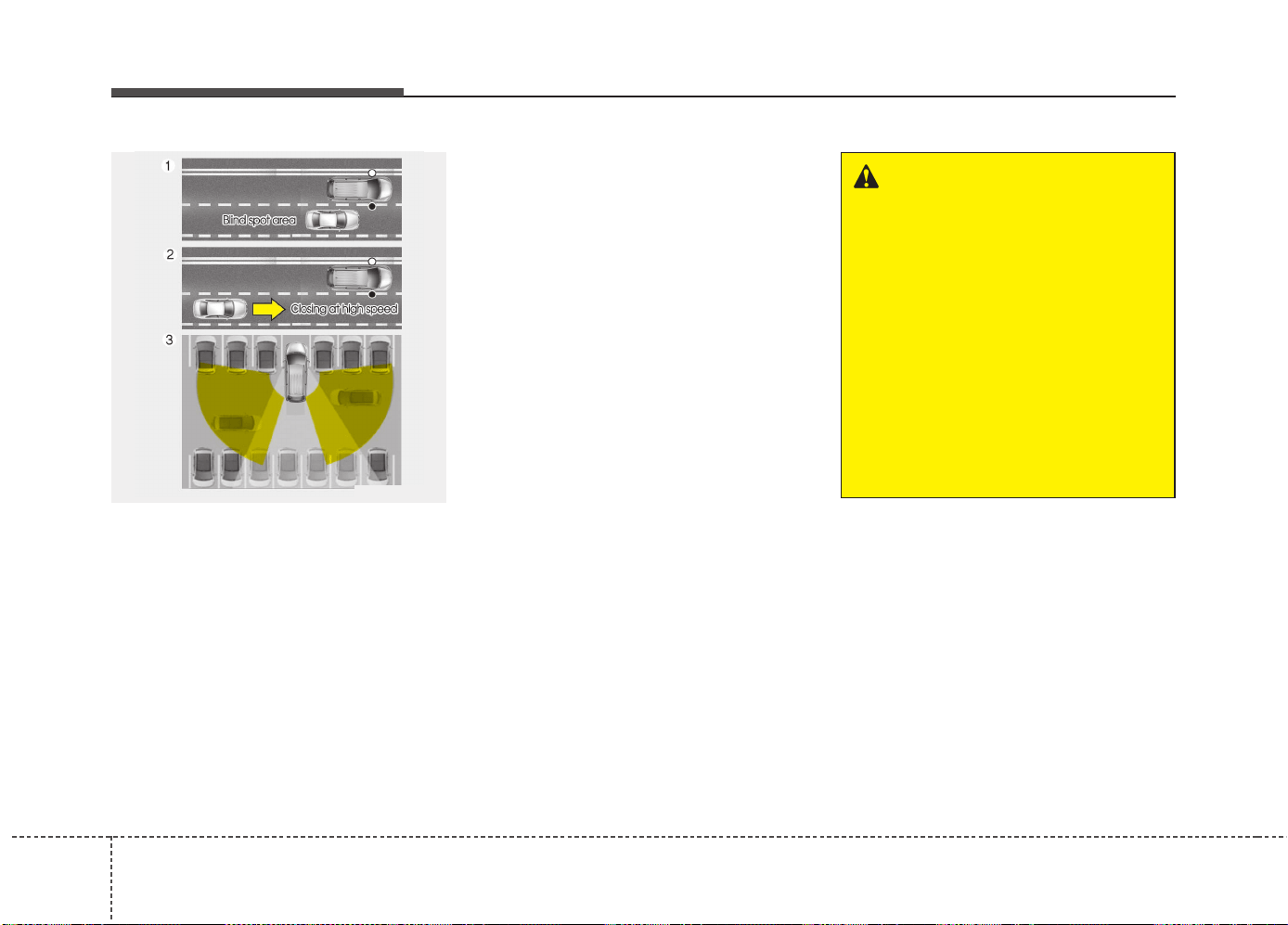
Driving your vehicle
745
The Blind Spot Detection System (BSD)
uses radar sensors in the rear bumper to
monitor and warn the driver of an
approaching vehicle in the driver's blind
spot area.
The system monitors the rear area of the
vehicle and provides information to the
driver with an audible alert and a indica-
tor on the outside rearview mirrors.
➀ BSD (Blind Spot Detection)
The blind spot detection range varies
relative to vehicle speed. Note that if
your vehicle is traveling much faster
than the vehicles around you, the
warning will not occur.
➁ LCA (Lane Change Assist)
The Lane Change Assist feature will
alert you when a vehicle is approach-
ing in an adjacent lane at a high rate of
speed. If the driver activates the turn
signal when the system detects an
oncoming vehicle, the system sounds
an audible alert. The time of alert
varies according to the speed differ-
ence between you and the approach-
ing vehicle.
➂ RCTA (Rear Cross Traffic Alert)
The Rear Cross Traffic Alert feature
monitors approaching cross traffic from
the left and right side of the vehicle
when your vehicle is in reverse. The
feature will operate when the vehicle is
moving in reverse below about 10 km/h
(6 mph). If oncoming cross traffic is
detected a warning chime will sound.
The time of alert varies according to
the speed difference between you and
the approaching vehicle.
BLIND SPOT DETECTION SYSTEM (BSD) (IF EQUIPPED)
OUM054176L
WARNING
• Always be aware of road condi-
tions while driving and be alert
for unexpected situations even
though the Blind Spot Detection
System is operating.
• The Blind Spot Detection System
(BSD) is not a substitute for prop-
er and safe driving. Always drive
safely and use caution when
changing lanes or backing up the
vehicle. The Blind Spot Detection
System (BSD) may not detect
every object alongside the vehi-
cle.
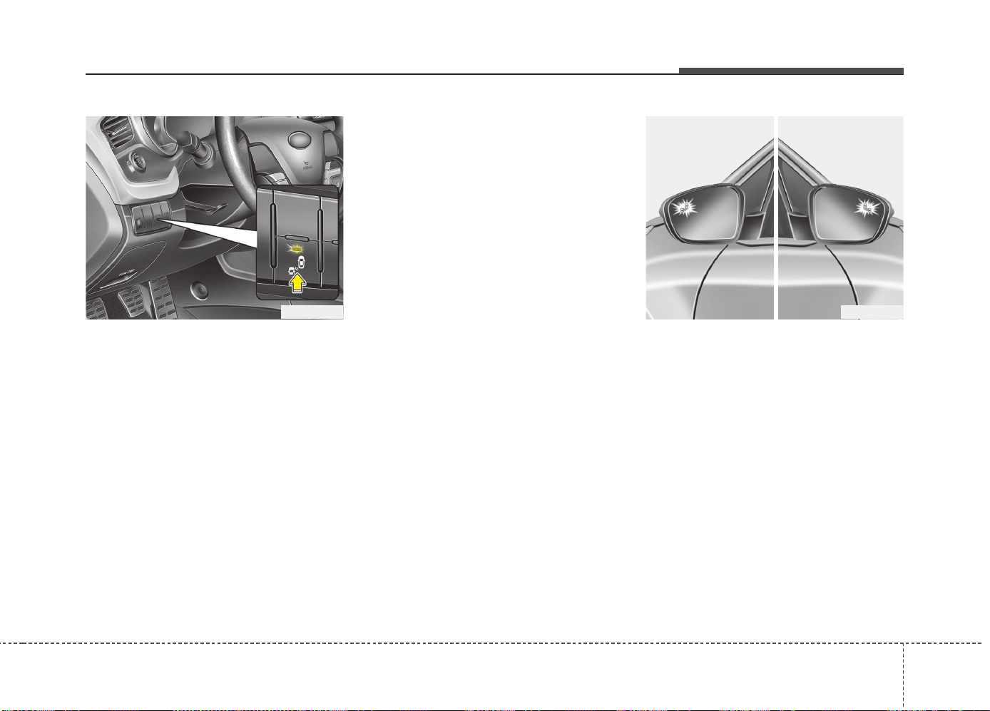
575
Driving your vehicle
BSD (Blind Spot Detection) /
LCA (Lane Change Assist)
Operating conditions
To operate:
Press the BSD switch with the Ignition
switch in the ON position.
The indicator on the BSD switch will illumi-
nate. When the vehicle speed exceeds 30
km/h (20 mph), the system will be activat-
ed.
To cancel:
Press the BSD switch again. The indicator
on the switch will go off.
When the system is not used, turn the sys-
tem off by turning off the switch.
✽✽
NOTICE
• If the vehicle is turned off then on
again, the BSD system returns to the
previous state.
• When the system is turned on, the
warning light will illuminate for 3 sec-
onds on the outside rearview mirror.
The system will activate when:
1. The system is on.
2. The vehicle speed is above about 30
km/h (20 mph).
3. An oncoming vehicle is detected in the
blind spot area.
First stage alert
If a vehicle is detected within the bound-
ary of the system, an amber warning light
will illuminate on the outside rearview
mirror.
Once the detected vehicle is no longer
within the blind spot area, the warning
will turn off according to the driving con-
ditions of the vehicle
OJD055061 OJD055059
1st stage
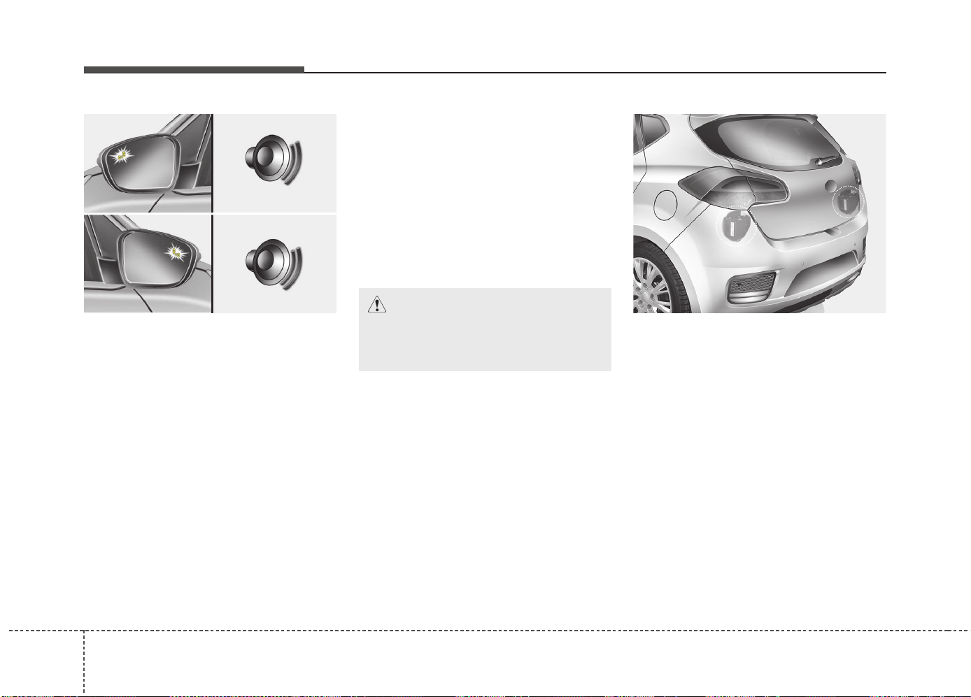
Driving your vehicle
765
Second stage alert
A warning chime to alert the driver will
activate when:
1. A vehicle has been detected in the
blind spot area by the radar system
(the warning light will illuminate on the
outside rearview mirror) AND
2. The turn signal is applied (same side
as where the vehicle is being detect-
ed).
When this alert is activated, the warning
light on the outside rearview mirror will
also blink.
If you turn off the turn signal indicator, the
warning chime will be deactivated.
- The second stage alarm can be deac-
tivated.
• To activate the alarm:
Go to the User Settings Mode →
Sound and select "BSD" on the LCD
display.
• To deactivate the alarm:
Go to the User Settings Mode →
Sound and deselect "BSD" on the LCD
display.
Non-operating condition
The sensors are located inside of the
rear bumper.
Always keep the rear bumper clean for
the system to work properly.
OJD055060
2st stage
CAUTION
The alarm function helps alert the
driver. Deactivate this function only
when it is necessary
OJD055058
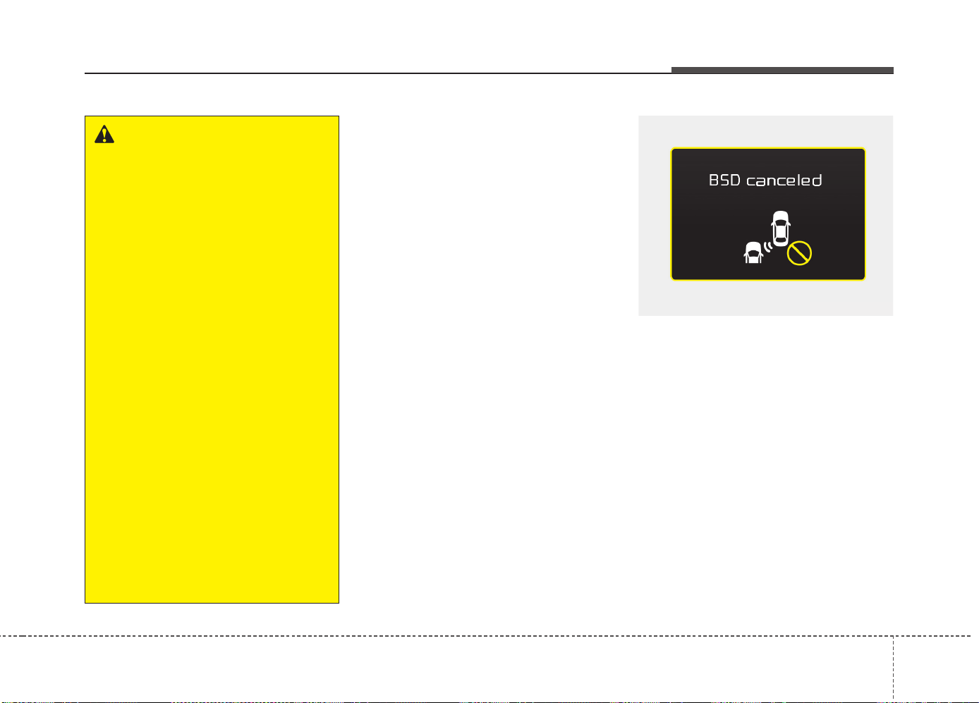
577
Driving your vehicle
✽✽
NOTICE
• The system may not work properly
when the bumper has been damaged,
or if the rear bumper has been
replaced or repaired.
• The sensing range differs somewhat
according to the width of the road.
When the road is narrow, the system
may detect other vehicles in the next
lane Or when the road is wide, the sys-
tem may not detect other vehicles in
the next lane.
• The system may turn off due to strong
electromagnetic waves.
Warning message
• This warning message may appear
when :
- One or both of the sensors on the
rear bumper is blocked by dirt or snow
or a foreign object.
- Driving in rural areas where the BSD
sensor does not detect another vehicle
for an extended period of time.
- When there is inclement weather
such as heavy snow or rain.
- A trailer or carrier is installed. (To use
the BSD system, remove the trailer or
carrier from your vehicle.)
If any of these conditions occur, the light
on the BSD switch and the system will
turn off automatically.
OUM054177L
WARNING
• The warning light on the outside
rearview mirror will illuminate
whenever a vehicle is detected at
the rear side by the system.
To avoid accidents, do not focus
only on the warning light and neg-
lect to see the surrounding of the
vehicle.
• Drive safely even though the vehi-
cle is equipped with a Blind Spot
Detection System (BSD) and Rear
Cross Traffic Alert (RCTA). Do not
solely rely on the system but check
your surrounding before changing
lanes or backing the vehicle up.
The system may not alert the driver
in some conditions so always
check your surroundings while
driving.
• The Blind Spot Detection System
(BSD) and Rear Cross Traffic Alert
(RCTA) are not a substitute for
proper and safe driving practices.
Always drive safely and use cau-
tion when changing lanes or back-
ing up your vehicle. The Blind Spot
Detection System (BSD) may not
detect every object alongside the
vehicle.
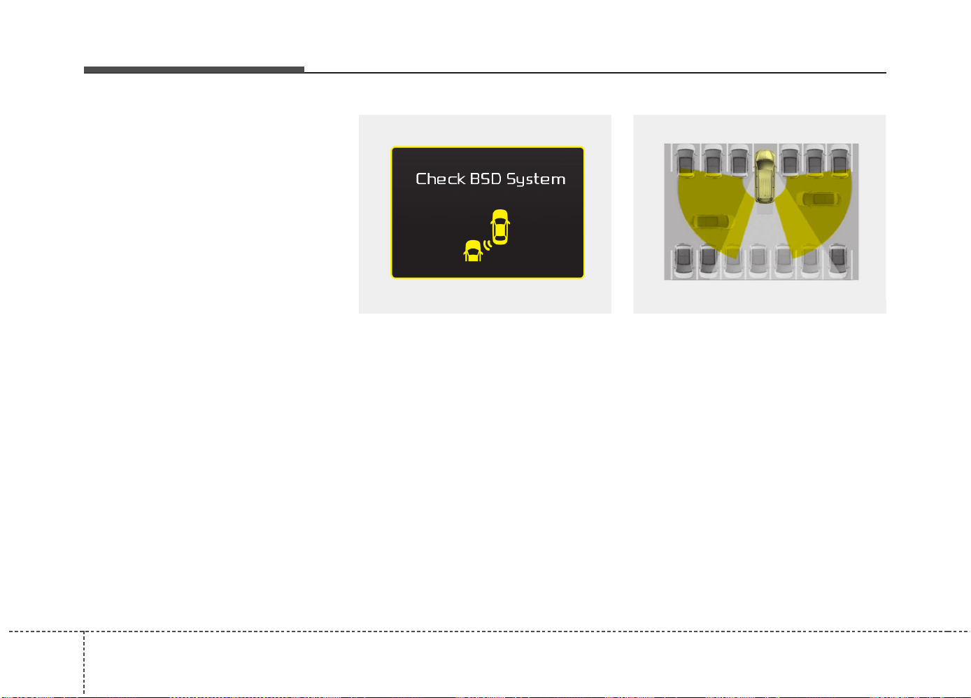
Driving your vehicle
785
When the BSD canceled warning mes-
sage is displayed in the cluster, check to
make sure that the rear bumper is free
from any dirt or snow in the areas where
the sensor is located. Remove any dirt,
snow, or foreign material that could inter-
fere with the radar sensors.
After any dirt or debris is removed, the
BSD system should operate normally
after about 10 minutes of driving the
vehicle.
If the system still does not operate nor-
mally have your vehicle inspected by an
authorized Kia dealer.
If there is a problem with the BSD sys-
tem, a warning message will appear and
the light on the switch will turn off. The
system will turn off automatically. We rec-
ommend that you have your vehicle
inspected by an authorized Kia dealer.
RCTA (Rear cross traffic alert)
The Rear Cross Traffic Alert feature mon-
itors approaching cross traffic from the
left and right side of the vehicle when
your vehicle is in reverse.
OYP054026KOUM054178L
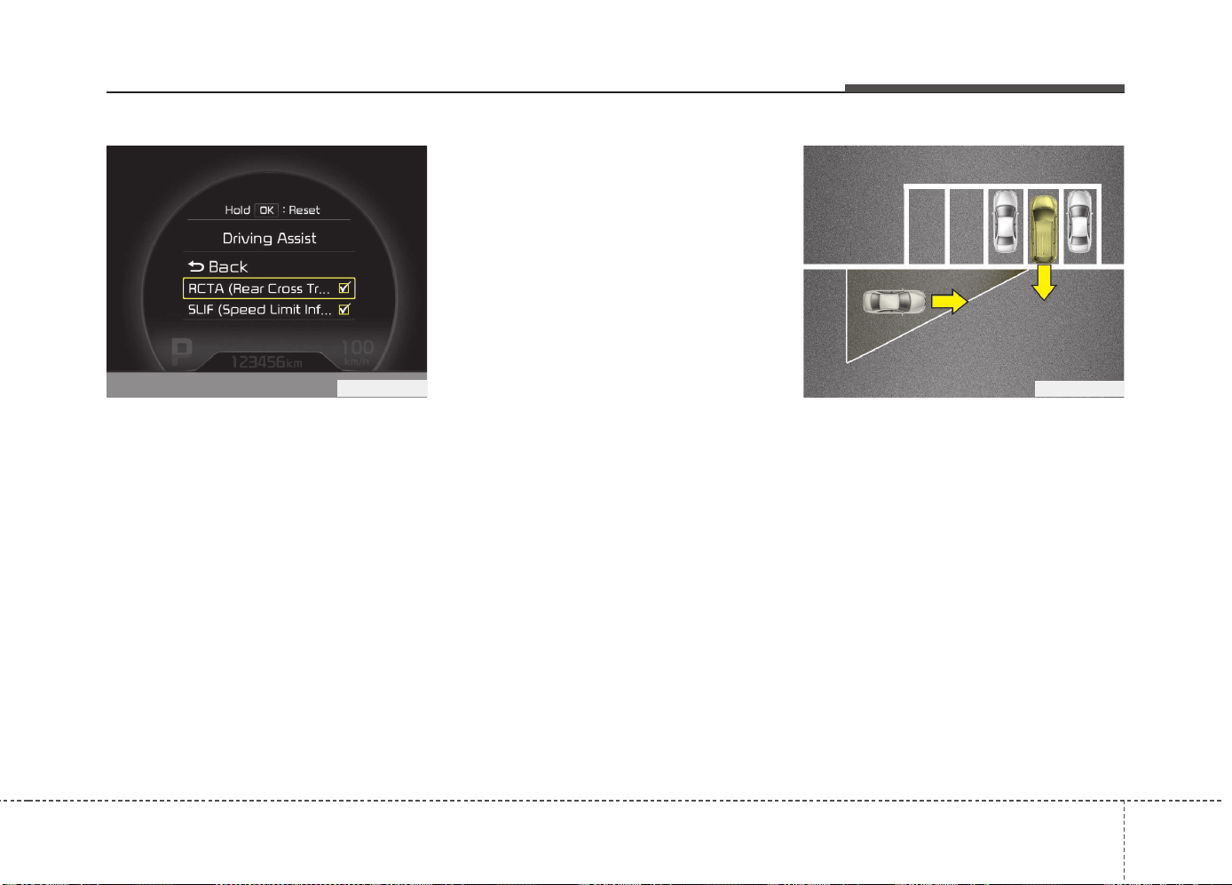
579
Driving your vehicle
Operating conditions
• Select RCTA (Rear Cross Traffic Alert)
in "User Settings" under "Driving Assist"
on the instrument cluster. The system
will turn on and stand by to be activated.
• Select RCTA again, to turn the system
off.
• If the vehicle is turned off and on
again, the RCTA system will return to
the state right before the vehicle was
turned off. Turn the RCTA system off
when not in use.
• The system is operated when the vehi-
cle speed is below 10km/h (6.2mph)
with the shift lever in R (Reverse).
✽✽
NOTICE
The Rear Cross Traffic Alert (RCTA)
detecting range is approximately
0.5 m ~ 20 m (1 ft ~ 65 ft). An approach-
ing vehicle will be detected if their vehi-
cle speed is within 4 km/h ~ 36 km/h (2.5
~ 22.5 mph ).
Note that the detecting range may vary
under certain conditions. As always, use
caution and pay close attention to your
surroundings when backing up your
vehicle.
Warning type
• If the vehicle detected by the sensors
approaches your vehicle, the warning
chime will sound, the warning light on
the outside rearview mirror will blink.
• If the detected vehicle is out of detec-
tion range, moving away in the oppo-
site direction or moving slow, the warn-
ing is cancelled.
• The system may not operate properly
due to other factors or circumstances.
Always pay attention to your surround-
ing.
• If the sensing area near the rear
bumper is blocked by either a wall or
barrier or by a parked vehicle, the sys-
tem sensing area may be reduced.
OYP054027KOJD055124L

Driving your vehicle
805
The BSD indicator on the outer side view
mirror may not illuminate properly when:
• The outside rearview mirror housing is
damaged.
• The mirror is covered with dirt, snow,
or debris.
• The window is covered with dirt, snow,
or debris.
• The window is tinted.
Driver’s Attention
The driver must be cautious in the below
situations, because the system may not
detect other vehicles or objects in certain
circumstances.
• The vehicle drives on a curved road or
through a tollgate.
• The vehicle is turning left or right at a
crossroad.
• The sensor is polluted with rain, snow,
mud, etc.
• The rear bumper where the sensor is
located is covered with a foreign object
such as a bumper sticker, a bumper
guard, a bike rack, etc.
• The rear bumper is damaged, or the
sensor is out of the original default
position.
• The vehicle height gets lower or higher
due to heavy loading in the luggage
compartment, abnormal tire pressure,
etc.
• The vehicle drives in inclement weath-
er such as heavy rain or snow.
• There is a fixed object near the vehicle,
such as a guardrail, person, animal,
etc.
• The vehicle is driven near areas con-
taining metal substances such as a
construction zone, railroad, etc.
• A big vehicle is near such as a bus or
truck.
• A motorcycle or bicycle is near.
• A flat trailer is near.
• If the vehicle has started at the same
time as the vehicle next to you and has
accelerated.
• When the other vehicle passes at a
very fast speed.
• While changing lanes.
• When going down or up a steep,
uneven road.
• When the other vehicle approaches
very close.
• When a trailer or carrier is installed.
• When the temperature near the rear
bumper area is high or low.
• When the sensors are blocked by other
vehicles, walls or parking-lot pillars.
• When the detected vehicle also moves
back, as your vehicle drives back.
• If there are small objects in the detect-
ing area such as a shopping cart or a
baby stroller.
• If there is a low height vehicle such as
a sports car.
• When other vehicles are close to your
vehicle.
• When the vehicle in the next lane
moves two lanes away from you OR
when the vehicle two lanes away
moves to the next lane from you.
• When driving through a narrow road
with many plants.
• When driving through a large area with
few cars or structures around, such as
a desert, rural area, etc.
• When driving on wet surface.

581
Driving your vehicle
ECONOMICAL OPERATION
Your vehicle's fuel economy depends
mainly on your style of driving, where you
drive and when you drive.
Each of these factors affects how many
kilometers (miles) you can get from a
liter (gallon) of fuel. To operate your vehi-
cle as economically as possible, use the
following driving suggestions to help
save money in both fuel and repairs:
• Drive smoothly. Accelerate at a moder-
ate rate. Do not make "jack-rabbit"
starts or full-throttle shifts and maintain
a steady cruising speed. Do not race
between stoplights. Try to adjust your
speed to the traffic so you do not have
to change speeds unnecessarily. Avoid
heavy traffic whenever possible.
Always maintain a safe distance from
other vehicles so you can avoid unnec-
essary braking. This also reduces
brake wear.
• Drive at a moderate speed. The faster
you drive, the more fuel your vehicle
uses. Driving at a moderate speed,
especially on the highway, is one of the
most effective ways to reduce fuel con-
sumption.
• Do not "ride" the brake or clutch pedal.
This can increase fuel consumption
and also increase wear on these com-
ponents. In addition, driving with your
foot resting on the brake pedal may
cause the brakes to overheat, which
reduces their effectiveness and may
lead to more serious consequences.
• Take care of your tires. Keep them
inflated to the recommended pressure.
Incorrect inflation, either too much or
too little, results in unnecessary tire
wear. Check the tire pressures at least
once a month.
• Be sure that the wheels are aligned
correctly. Improper alignment can
result from hitting curbs or driving too
fast over irregular surfaces. Poor align-
ment causes faster tire wear and may
also result in other problems as well as
greater fuel consumption.
• Keep your vehicle in good condition.
For better fuel economy and reduced
maintenance costs, maintain your vehi-
cle in accordance with the mainte-
nance schedule. If you drive your vehi-
cle in severe conditions, more frequent
maintenance is required.
• Keep your vehicle clean. For maximum
service, your vehicle should be kept
clean and free of corrosive materials. It
is especially important that mud, dirt,
ice, etc. not be allowed to accumulate
on the underside of the vehicle. This
extra weight can result in increased
fuel consumption and also contribute
to corrosion.
• Travel lightly. Do not carry unnecessary
weight in your vehicle. Weight reduces
fuel economy.
• Do not let the engine idle longer than
necessary. If you are waiting (and not
in traffic), turn off your engine and
restart only when you're ready to go.
Driving your vehicle
825
• Remember, your vehicle does not
require extended warm-up. After the
engine has started, allow the engine to
run for 10 to 20 seconds prior to plac-
ing the vehicle in gear. In very cold
weather, however, give your engine a
slightly longer warm-up period.
• Do not "lug" or "over-rev" the engine.
Lugging is driving too slowly in too
high a gear resulting engine bucking. If
this happens, shift to a lower gear.
Over-revving is racing the engine
beyond its safe limit. This can be avoid-
ed by shifting at the recommended
speeds.
• Use your air conditioning sparingly.
The air conditioning system is operat-
ed by engine power so your fuel econ-
omy is reduced when you use it.
• Open windows at high speeds can
reduce fuel economy.
• Fuel economy is less in crosswinds
and headwinds. To help offset some of
this loss, slow down when driving in
these conditions.
Keeping a vehicle in good operating con-
dition is important both for economy and
safety. We recommend in general that the
vehicle be serviced by an authorized Kia
dealer.
WARNING - Engine off dur-
ing motion
Never turn the engine off to coast
down hills or anytime the vehicle is
in motion. The power steering and
power brakes will not function
properly without the engine run-
ning. Instead, keep the engine on
and downshift to an appropriate
gear for engine braking effect. In
addition, turning off the ignition
while driving could engage the
steering wheel lock (if equipped)
resulting in loss of vehicle steering
which could cause serious injury
or death.
583
Driving your vehicle
Hazardous driving conditions
When hazardous driving conditions are
encountered such as water, snow, ice,
mud, sand, or similar hazards, follow
these suggestions:
• Drive cautiously and allow extra dis-
tance for braking.
• Avoid sudden braking or steering.
• When braking with non-ABS brakes
pump the brake pedal with a light up-
and-down motion until the vehicle is
stopped.
• If stalled in snow, mud, or sand, use
second gear. Accelerate slowly to
avoid spinning the drive wheels.
• Use sand, rock salt, tire chains, or
other non-slip material under the drive
wheels to provide traction when stalled
in ice, snow, or mud.
Rocking the vehicle
If it is necessary to rock the vehicle to
free it from snow, sand, or mud, first turn
the steering wheel right and left to clear
the area around your front wheels. Then,
shift back and forth between 1 (First) and
R (Reverse) in vehicles equipped with a
manual transaxle or R (Reverse) and any
forward gear in vehicles equipped with
an automatic transaxle. Do not race the
engine, and spin the wheels as little as
possible. If you are still stuck after a few
tries, have the vehicle pulled out by a tow
vehicle to avoid engine overheating and
possible damage to the transaxle.
SPECIAL DRIVING CONDITIONS
WARNING - Downshifting
Downshifting with an automatic
transaxle, while driving on slippery
surfaces can cause an accident.
The sudden change in tire speed
could cause the tires to skid. Be
careful when downshifting on slip-
pery surfaces.
WARNING - ABS
Do not pump the brake pedal on a
vehicle equipped with ABS.
CAUTION
Prolonged rocking may cause
engine over-heating, transaxle dam-
age or failure, and tire damage.
Driving your vehicle
845
✽✽
NOTICE
The ESC system should be turned OFF
prior to rocking the vehicle.
Smooth cornering
Avoid braking or gear changing in cor-
ners, especially when roads are wet.
Ideally, corners should always be taken
under gentle acceleration. If you follow
these suggestions, tire wear will be held
to a minimum.
Driving at night
Because night driving presents more
hazards than driving in the daylight, here
are some important tips to remember:
• Slow down and keep more distance
between you and other vehicles, as it
may be more difficult to see at night,
especially in areas where there may
not be any street lights.
• Adjust your mirrors to reduce the glare
from other driver's headlights.
• Keep your headlights clean and prop-
erly aimed on vehicles not equipped
with the automatic headlight aiming
feature. Dirty or improperly aimed
headlights will make it much more diffi-
cult to see at night.
• Avoid staring directly at the headlights
of oncoming vehicles. You could be
temporarily blinded, and it will take
several seconds for your eyes to read-
just to the darkness.
Driving in the rain
Rain and wet roads can make driving
dangerous, especially if you’re not pre-
pared for the slick pavement. Here are a
few things to consider when driving in the
rain:
• A heavy rainfall will make it harder to
see and will increase the distance
needed to stop your vehicle, so slow
down.
• Keep your windshield wiping equip-
ment in good shape. Replace your
windshield wiper blades when they
show signs of streaking or missing
areas on the windshield.
• If your tires are not in good condition,
making a quick stop on wet pavement
can cause a skid and possibly lead to
an accident. Be sure your tires are in
good shape.
• Turn on your headlights to make it eas-
ier for others to see you.
• Driving too fast through large puddles
can affect your brakes. If you must go
through puddles, try to drive through
them slowly.
• If you believe you may have gotten
your brakes wet, apply them lightly
while driving until normal braking oper-
ation returns.
WARNING - Spinning tires
Do not spin the wheels, especially
at speeds more than 56 km/h (35
mph). Spinning the wheels at high
speeds when the vehicle is station-
ary could cause a tire to overheat
which could result in tire damage
that may injure bystanders.
WARNING
If your vehicle becomes stuck in
snow, mud, sand, etc., then you
may attempt to rock the vehicle free
by moving it forward and backward.
Do not attempt this procedure if
people or objects are anywhere
near the vehicle. During the rocking
operation the vehicle may suddenly
move forward or backward as it
becomes unstuck, causing injury
or damage to nearby people or
objects.
585
Driving your vehicle
Driving in flooded areas
Avoid driving through flooded areas
unless you are sure the water is no high-
er than the bottom of the wheel hub.
Drive through any water slowly. Allow
adequate stopping distance because
brake performance may be affected.
After driving through water, dry the
brakes by gently applying them several
times while the vehicle is moving slowly.
Driving off-road
Drive carefully off-road because your
vehicle may be damaged by rocks or
roots of trees. Become familiar with the
off-road conditions where you are going
to drive before you begin driving.
Highway driving
Tires
Adjust the tire inflation pressures to
specification. Low tire inflation pressures
will result in overheating and possible
failure of the tires.
Avoid using worn or damaged tires which
may result in reduced traction or tire fail-
ure.
✽✽
NOTICE
Never exceed the maximum tire inflation
pressure shown on the tires.
Fuel, engine coolant and engine oil
High speed travel consumes more fuel
than urban motoring. Do not forget to
check both engine coolant and engine oil.
Drive belt
A loose or damaged drive belt may result
in overheating of the engine.
WARNING
• Underinflated or overinflated
tires can cause poor handling,
loss of vehicle control, and sud-
den tire failure leading to acci-
dents, injuries, and even death.
Always check the tires for proper
inflation before driving. For prop-
er tire pressures, refer to chapter
8, “Tires and wheels”.
(Continued)
(Continued)
• Driving on tires with no or insuffi-
cient tread is dangerous. Worn-
out tires can result in loss of
vehicle control, collisions, injury,
and even death. Worn-out tires
should be replaced as soon as
possible and should never be
used for driving. Always check
the tire tread before driving your
vehicle. For further information
and tread limits, refer to chapter
7, “Tires and wheels”.
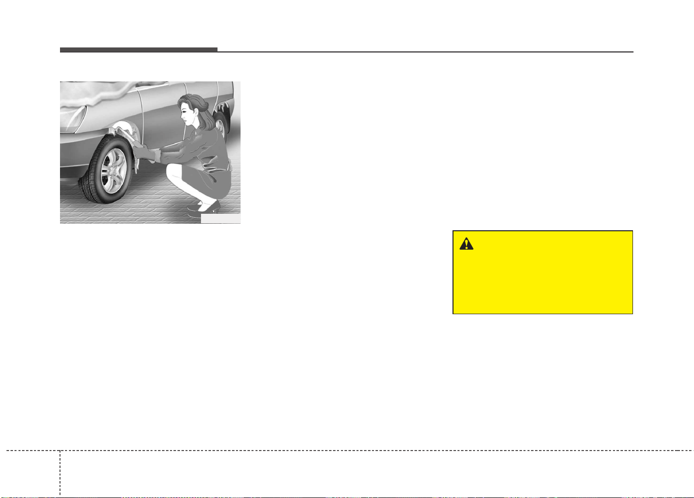
Driving your vehicle
865
Severe weather conditions in the winter
result in greater wear and other prob-
lems. To minimize the problems of winter
driving, you should follow these sugges-
tions:
Snowy or Icy conditions
To drive your vehicle in deep snow, it may
be necessary to use snow tires or to
install tire chains on your tires. If snow
tires are needed, it is necessary to select
tires equivalent in size and type of the
original equipment tires. Failure to do so
may adversely affect the safety and han-
dling of your vehicle. Furthermore,
speeding, rapid acceleration, sudden
brake applications, and sharp turns are
potentially very hazardous practices.
During deceleration, use engine braking
to the fullest extent. Sudden brake appli-
cations on snowy or icy roads may cause
skids to occur. You need to keep suffi-
cient distance between the vehicle in
operation in front and your vehicle. Also,
apply the brake gently. It should be noted
that installing tire chains on the tire will
provide a greater driving force, but will
not prevent side skids.
✽✽
NOTICE
Tire chains are not legal in all countries.
Check the country laws before fitting
tire chains.
Snow tires
If you mount snow tires on your vehicle,
make sure they are radial tires of the
same size and load range as the original
tires. Mount snow tires on all four wheels
to balance your vehicle’s handling in all
weather conditions. Keep in mind that the
traction provided by snow tires on dry
roads may not be as high as your vehi-
cle's original equipment tires. You should
drive cautiously even when the roads are
clear. Check with the tire dealer for max-
imum speed recommendations.
Do not install studded tires without first
checking local, state and municipal regu-
lations for possible restrictions against
their use.
WINTER DRIVING
WARNING - Snow tire size
Snow tires should be equivalent in
size and type to the vehicle's stan-
dard tires. Otherwise, the safety
and handling of your vehicle may
be adversely affected.
1VQA3005
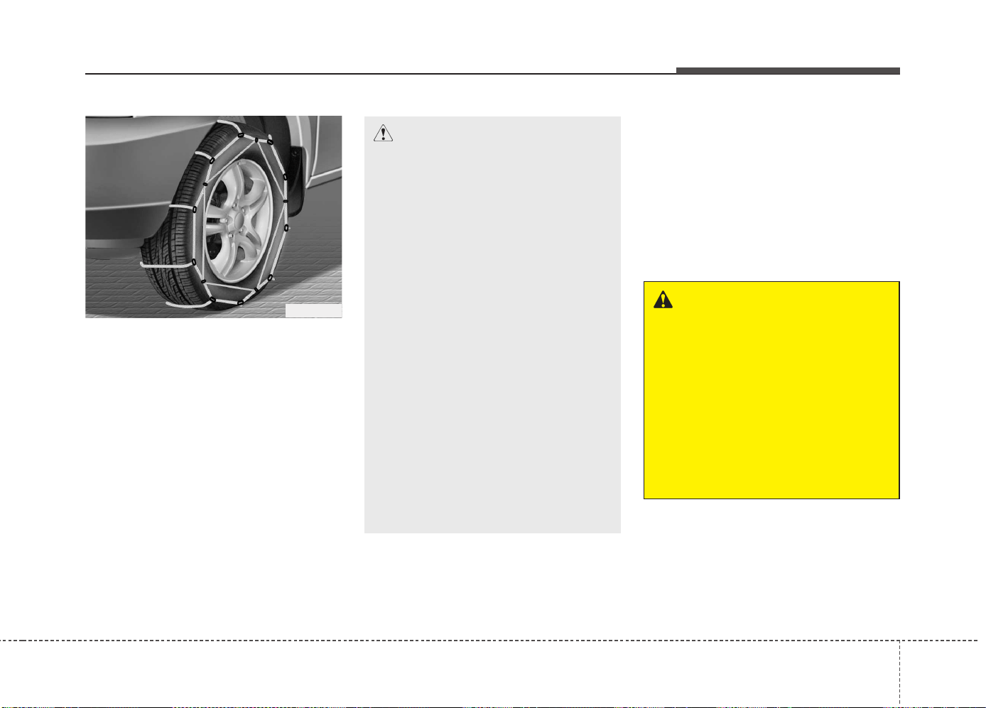
587
Driving your vehicle
Tire chains
Since the sidewalls of radial tires are
thinner, they can be damaged by mount-
ing some types of snow chains on them.
Therefore, the use of snow tires is rec-
ommended instead of snow chains. Do
not mount tire chains on vehicles
equipped with aluminum wheels; snow
chains may cause damage to the wheels.
If snow chains must be used, use wire-
type chains with a thickness of less than
15 mm (0.59 in). Damage to your vehicle
caused by improper snow chain use is
not covered by your vehicle manufactur-
ers warranty.
Install tire chains only on the front tires.
Chain installation
When installing chains, follow the manu-
facturer's instructions and mount them as
tightly as you can. Drive slowly with
chains installed. If you hear the chains
contacting the body or chassis, stop and
tighten them. If they still make contact,
slow down until it stops. Remove the
chains as soon as you begin driving on
cleared roads.
CAUTION
• Make sure the snow chains are
the correct size and type for your
tires. Incorrect snow chains can
cause damage to the vehicle body
and suspension and may not be
covered by your vehicle manufac-
turer warranty. Also, the snow
chain connecting hooks may be
damaged from contacting vehicle
components causing the snow
chains to come loose from the
tire. Make sure the snow chains
are SAE class “S” certified.
• Always check chain installation
for proper mounting after driving
approximately 0.5 to 1 km (0.3 to
0.6 miles) to ensure safe mount-
ing. Retighten or remount the
chains if they are loose.
• If your vehicle has 225/45R17 or
225/40ZR18 size tires do not use
tire chain; they can damage your
vehicle (wheel, suspension and
body).
WARNING
- Mounting chains
When mounting snow chains, park
the vehicle on level ground away
from traffic. Turn on the vehicle
Hazard Warning flashers and place
a triangular emergency warning
device behind the vehicle if avail-
able. Always place the vehicle in P
(Park), apply the parking brake and
turn off the engine before installing
snow chains.
1VQA3007
Driving your vehicle
885
Use high quality ethylene glycol
coolant
Your vehicle is delivered with high quality
ethylene glycol coolant in the cooling
system. It is the only type of coolant that
should be used because it helps prevent
corrosion in the cooling system, lubri-
cates the water pump and prevents
freezing. Be sure to replace or replenish
your coolant in accordance with the
maintenance schedule. Before winter,
have your coolant tested to assure that
its freezing point is sufficient for the tem-
peratures anticipated during the winter.
Check battery and cables
Winter puts additional burdens on the
battery system. Visually inspect the bat-
tery and cables as described in chapter
7. We recommend that the system be
checked by an authorized Kia dealer.
Change to "winter weight" oil if
necessary
In some climates it is recommended that
a lower viscosity "winter weight" oil be
used during cold weather. See chapter 8
for recommendations. If you aren't sure
what weight oil you should use, we rec-
ommend that you consult an authorized
Kia dealer.
Check spark plugs and ignition
system
Inspect your spark plugs as described in
chapter 7 and replace them if necessary.
Also check all ignition wiring and compo-
nents to be sure they are not cracked,
worn or damaged in any way.
CAUTION
• Chains that are the wrong size or
improperly installed can damage
your vehicle's brake lines, sus-
pension, body and wheels.
• Stop driving and retighten the
chains any time you hear them
hitting the vehicle.
WARNING - Tire chains
• The use of chains may adversely
affect vehicle handling.
• Do not exceed 30 km/h (20 mph)
or the chain manufacturer’s rec-
ommended speed limit, whichev-
er is lower.
• Drive carefully and avoid bumps,
holes, sharp turns, and other
road hazards, which may cause
the vehicle to bounce.
• Avoid sharp turns or locked-
wheel braking.

589
Driving your vehicle
To keep locks from freezing
To keep the locks from freezing, squirt an
approved de-icer fluid or glycerine into
the key opening. If a lock is covered with
ice, squirt it with an approved de-icing
fluid to remove the ice. If the lock is
frozen internally, you may be able to thaw
it out by using a heated key. Handle the
heated key with care to avoid injury.
Use approved window washer
anti-freeze in system
To keep the water in the window washer
system from freezing, add an approved
window washer anti-freeze solution in
accordance with instructions on the con-
tainer. Window washer anti-freeze is
available from an authorized Kia dealer
and most auto parts outlets. Do not use
engine coolant or other types of anti-
freeze as these may damage the paint
finish.
Don't let your parking brake
freeze
Under some conditions your parking
brake can freeze in the engaged position.
This is most likely to happen when there
is an accumulation of snow or ice around
or near the rear brakes or if the brakes
are wet. If there is a risk the parking
brake may freeze, apply it only temporar-
ily while you put the shift lever in P (auto-
matic transaxle) or in first or reverse gear
(manual transaxle) and block the rear
wheels so the vehicle cannot roll. Then
release the parking brake.
Don't let ice and snow accumu-
late underneath
Under some conditions, snow and ice
can build up under the fenders and inter-
fere with the steering. When driving in
severe winter conditions where this may
happen, you should periodically check
underneath the vehicle to be sure the
movement of the front wheels and the
steering components is not obstructed.
Carry emergency equipment
Depending on the severity of the weath-
er, you should carry appropriate emer-
gency equipment. Some of the items you
may want to carry include tire chains, tow
straps or chains, flashlight, emergency
flares, sand, shovel, jumper cables, win-
dow scraper, gloves, ground cloth, cover-
alls, blanket, etc.
Driving your vehicle
905
If you are considering towing with your
vehicle, you should first check with your
country's Department of Motor Vehicles
to determine their legal requirements.
Since laws vary the requirements for tow-
ing trailers, cars, or other types of vehicles
or apparatus may differ. We recommend
that you ask an authorized Kia dealer.
✽✽
NOTICE - For Europe
• The technically permissible maximum
load on the rear axle(s) may be
exceeded by not more than 15 % and
the technically permissible maximum
laden mass of the vehicle may be
exceeded by not more than 10 % or
100 kg (220.4 lbs), whichever value is
lower. In this case, do not exceed 100
km/h (62.1 mph) for vehicle of catego-
ry M1 or 80 km/h (49.7 mph) for vehi-
cle of category N1.
• When towing a trailer, the additional
load imposed at the trailer coupling
device may cause the rear tire maxi-
mum load ratings to be exceeded, but
not by more than 15%. In such a case,
do not exceed 100km/h, and the rear
tire pressure should be at least 20
kPa(0.2 bar) above the tire pressure(s)
as recommended for normal use (i.e.
without a trailer attached).
TRAILER TOWING
CAUTION
Pulling a trailer improperly can
damage your vehicle and result in
costly repairs not covered by your
warranty. To pull a trailer correctly,
follow the advice in this chapter.
WARNING - Towing a trailer
If you don't use the correct equip-
ment and/or drive improperly, you
can lose control when you pull a trail-
er. For example, if the trailer is too
heavy, the brakes may not work well -
or even at all. You and your passen-
gers could be seriously or fatally
injured. Pull a trailer only if you have
followed all the steps in this chapter.
WARNING - Weight limits
Before towing, make sure the total
trailer weight, GCW (gross combi-
nation weight), GVW (gross vehicle
weight), GAW (gross axle weight )
and trailer tongue load are all with-
in the limits.
WARNING
When you tow the trailer, make sure
that you turn off the ISG function.
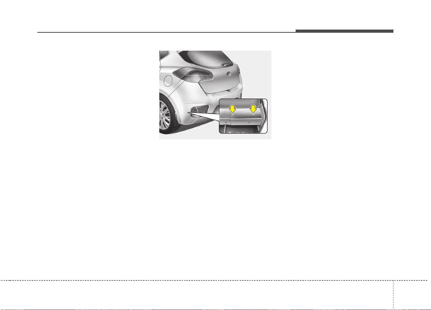
591
Driving your vehicle
Your vehicle can tow a trailer. To identify
what the vehicle trailering capacity is for
your vehicle, you should read the infor-
mation in “Weight of the trailer” that
appears later in this chapter.
Remember that trailering is different than
just driving your vehicle by itself.
Trailering means changes in handling,
durability, and fuel economy. Successful,
safe trailering requires correct equip-
ment, and it has to be used properly.
This chapter contains many time-tested,
important trailering tips and safety rules.
Many of these are important for your
safety and that of your passengers.
Please read this chapter carefully before
you pull a trailer.
Load-pulling components such as the
engine, transaxle, wheel assemblies, and
tires are forced to work harder against the
load of the added weight. The engine is
required to operate at relatively higher
speeds and under greater loads.This addi-
tional burden generates extra heat. The
trailer also considerably adds wind resist-
ance, increasing the pulling requirements.
Hitches
It's important to have the correct hitch
equipment. Crosswinds, large trucks
going by, and rough roads are a few rea-
sons why you’ll need the right hitch. Here
are some rules to follow:
• Do you have to make any holes in the
body of your vehicle when you install a
trailer hitch? If you do, then be sure to
seal the holes later when you remove
the hitch.
If you do not seal them, deadly carbon
monoxide (CO) from your exhaust can
get into your vehicle, as well as dirt and
water.
• The bumpers on your vehicle are not
intended for hitches. Do not attach
rental hitches or other bumper-type
hitches to them. Use only a frame-
mounted hitch that does not attach to
the bumper.
• A Kia accessory trailer hitch is avail-
able at an authorized Kia dealer.
OJD055024
Driving your vehicle
925
Safety chains
You should always attach chains
between your vehicle and your trailer.
Cross the safety chains under the tongue
of the trailer so that the tongue will not
drop to the road if it becomes separated
from the hitch.
Instructions about safety chains may be
provided by the hitch manufacturer or by
the trailer manufacturer. Follow the man-
ufacturer’s recommendation for attaching
safety chains. Always leave just enough
slack so you can turn with your trailer.
And, never allow safety chains to drag on
the ground.
Trailer brakes
If your trailer is equipped with a braking
system, make sure it conforms to your
country’s regulations and that it is prop-
erly installed and operating correctly.
If your trailer weight exceeds the maxi-
mum allowed weight without trailer
brakes, then the trailer will also require its
own brakes as well. Be sure to read and
follow the instructions for the trailer
brakes so you’ll be able to install, adjust
and maintain them properly.
• Do not tap into or modify your vehicle's
brake system.
Driving with a trailer
Towing a trailer requires a certain amount
of experience. Before setting out for the
open road, you must get to know your
trailer. Acquaint yourself with the feel of
handling and braking with the added
weight of the trailer. And always keep in
mind that the vehicle you are driving is
now a good deal longer and not nearly so
responsive as your vehicle is by itself.
Before you start, check the trailer hitch
and platform, safety chains, electrical
connector(s), lights, tires and mirror
adjustment. If the trailer has electric
brakes, start your vehicle and trailer mov-
ing and then apply the trailer brake con-
troller by hand to be sure the brakes are
working. This lets you check your electri-
cal connection at the same time.
During your trip, check occasionally to be
sure that the load is secure, and that the
lights and any trailer brakes are still work-
ing.
WARNING - Trailer brakes
Do not use a trailer with its own
brakes unless you are absolutely
certain that you have properly set
up the brake system. This is not a
task for amateurs. Use an experi-
enced, competent trailer shop for
this work.
593
Driving your vehicle
Following distance
Stay at least twice as far behind the vehi-
cle ahead as you would when driving
your vehicle without a trailer. This can
help you avoid situations that require
heavy braking and sudden turns.
Passing
You’ll need more passing distance up
ahead when you’re towing a trailer. And,
because of the increased vehicle length,
you’ll need to go much farther beyond the
passed vehicle before you can return to
your lane.
Backing up
Hold the bottom of the steering wheel
with one hand. Then, to move the trailer
to the left, just move your hand to the left.
To move the trailer to the right, move your
hand to the right. Always back up slowly
and, if possible, have someone guide you.
Making turns
When you’re turning with a trailer, make
wider turns than normal. Do this so your
trailer won’t strike soft shoulders, curbs,
road signs, trees, or other objects. Avoid
jerky or sudden maneuvers. Signal well
in advance.
Turn signals when towing a trailer
When you tow a trailer, your vehicle has
to have a different turn signal flasher and
extra wiring. The green arrows on your
instrument panel will flash whenever you
signal a turn or lane change. Properly
connected, the trailer lights will also flash
to alert other drivers you’re about to turn,
change lanes, or stop.
When towing a trailer, the green arrows
on your instrument panel will flash for
turns even if the bulbs on the trailer are
burned out. Thus, you may think drivers
behind you are seeing your signals
when, in fact, they are not. It is important
to check occasionally to be sure the trail-
er bulbs are still working. You must also
check the lights every time you discon-
nect and then reconnect the wires.
Do not connect a trailer lighting system
directly to your vehicle’s lighting system.
Use only an approved trailer wiring har-
ness.
An authorized Kia dealer can assist you
in installing the wiring harness.
WARNING
Failure to use an approved trailer
wiring harness could result in dam-
age to the vehicle electrical system
and/or personal injury.
Driving your vehicle
945
Driving on grades
Reduce speed and shift to a lower gear
before you start down a long or steep
downgrade. If you don’t shift down, you
might have to use your brakes so much
that they would get hot and no longer
operate efficiently.
On a long uphill grade, shift down and
reduce your speed to around 70 km/h (45
mph) to reduce the possibility of engine
and transaxle overheating.
If your trailer weighs more than the max-
imum trailer weight without trailer brakes
and you have an automatic transaxle,
you should drive in D (Drive) when tow-
ing a trailer.
Operating your vehicle in D (Drive) when
towing a trailer will minimize heat build up
and extend the life of your transaxle.
CAUTION
• When towing a trailer on steep
grades (in excess of 6%) pay close
attention to the engine coolant
temperature gauge to ensure the
engine does not overheat.
If the coolant temperature red
warning light illuminates or the
coolant temperature gauge
moves towards “130”, pull over
and stop as soon as it is safe to
do so, and allow the engine to idle
until it cools down. You may pro-
ceed once the engine has cooled
sufficiently.
• You must decide driving speed
depending on trailer weight and
uphill grade to reduce the possi-
bility of engine and transaxle
overheating.
(Continued)
(Continued)
• For vehicles equipped with a dual
clutch transmission when towing
a trailer on steep grades, the
clutch in the transmission could
overheat.
When the clutch is overheated,
the safe protection mode
engages. If the safe protection
mode engages, the gear position
indicator on the cluster blinks
with a chime sound.
At this time, a warning message
will appear on the LCD display
and driving may not be smooth.
If you ignore this warning, the driv-
ing condition may become worse.
To return to normal driving condi-
tion, stop the vehicle on a flat
road and apply the foot brake for
a few minutes before driving off.
595
Driving your vehicle
Parking on hills
Generally, if you have a trailer attached to
your vehicle, you should not park your
vehicle on a hill. People can be seriously
or fatally injured, and both your vehicle
and the trailer can be damaged if unex-
pectedly roll down hill.
However, if you ever have to park your
trailer on a hill, here is how to do it:
1. Pull the vehicle into the parking space.
Turn the steering wheel in the direction
of the curb (right if headed down hill,
left if headed up hill).
2. If the vehicle has a manual transaxle,
place the car in neutral. If the vehicle
has an automatic transaxle, place the
car in P (Park).
3. Set the parking brake and shut off the
vehicle.
4. Place chocks under the trailer wheels
on the down hill side of the wheels.
5. Start the vehicle, hold the brakes, shift
to neutral, release the parking brake
and slowly release the brakes until the
trailer chocks absorb the load.
6. Reapply the brakes, reapply the park-
ing brake and shift the vehicle to R
(Reverse) for manual transaxle or P
(Park) for automatic transaxle.
7. Shut off the vehicle and release the
vehicle brakes but leave the parking
brake set.
WARNING - Parking on a
hill
Parking your vehicle on a hill with a
trailer attached could cause seri-
ous injury or death, should the trail-
er break loose.
Do not apply the accelerator pedal
to hold the vehicle on an uphill.
WARNING - Parking brake
It can be dangerous to get out of
your vehicle if the parking brake is
not firmly set.
If you have left the engine running,
the vehicle can move suddenly. You
or others could be seriously or
fatally injured.

Driving your vehicle
965
When you are ready to leave after park-
ing on a hill
1. With the manual transaxle in Neutral
or automatic transaxle in P (Park),
apply your brakes and hold the brake
pedal down while you:
• Start your engine;
• Shift into gear; and
• Release the parking brake.
2. Slowly remove your foot from the
brake pedal.
3. Drive slowly until the trailer is clear of
the chocks.
4. Stop and have someone pick up and
store the chocks.
Maintenance when trailer towing
Your vehicle will need service more often
when you regularly pull a trailer.
Important items to pay particular atten-
tion to include engine oil, automatic
transaxle fluid, axle lubricant and cooling
system fluid. Brake condition is another
important item to frequently check. Each
item is covered in this manual, and the
Index will help you find them quickly. If
you’re trailering, it is a good idea to
review these chapters before you start
your trip.
Do not forget to also maintain your trailer
and hitch. Follow the maintenance
schedule that accompanied your trailer
and check it periodically. Preferably, con-
duct the check at the start of each day’s
driving. Most importantly, all hitch nuts
and bolts should be tight.
CAUTION
• Due to higher load during trailer
usage, overheating might occur
in hot days or during uphill driv-
ing. If the coolant gauge indicates
over-heating, switch off the air
conditioner and stop the vehicle
in a safe area to cool down the
engine.
• When towing check transaxle
fluid more frequently.
• If your vehicle is not equipped
with an air conditioner, you
should install a condenser fan to
improve engine performance
when towing a trailer.

597
Driving your vehicle
If you do decide to pull a trailer
Here are some important points if you decide to pull a trailer:
• Consider using a sway control. You can ask a hitch dealer about sway control.
• Do not do any towing with your car during its first 2,000 km (1,200 miles) in order to allow the engine to properly break in. Failure
to heed this caution may result in serious engine or transaxle damage.
• When towing a trailer, we recommend that you consult an authorized Kia dealer on additional requirements such as a towing kit, etc.
• Always drive your vehicle at a moderate speed (less than 100 km/h (60 mph)).
• On a long uphill grade, do not exceed 70 km/h (45 mph) or the posted towing speed limit, whichever is lower.
• The chart contains important considerations that have to do with weight:
Engine
Item
Gasoline
1.0L T-GDI
Gasoline
1.4L
Gasoline
1.6L MPI
Gasoline
1.6L GDI
Gasoline
1.6L T-GDI
Diesel
1.4L
Diesel
1.6L
M/T M/T M/T A/T M/T DCT M/T M/T M/T DCT
Maximum
trailer weight
kg (Ibs.)
Without brake
System
600
(1,323)
600
(1,323)
600
(1,323)
600
(1,323)
600
(1,323)
600
(1,323)
600
(1,323)
650
(1,433)
650
(1,433)
650
(1,433)
With brake
System
1,200
(2,646)
1,200
(2,646)
1,300
(2,866)
1200
(2,646)
1,400
(3,086)
1,300
(2,866)
1,400
(3,086)
1,500
(3,307)
1,500
(3,307)
1,500
(3,307)
Maximum permissible static
vertical load on the coupling
device
kg (Ibs.)
60
(132)
60
(132)
60
(132)
60
(132)
60
(132)
60
(132)
60
(132)
75
(165)
75
(165)
75
(165)
Recommended distance from
rear wheel center to coupling
point
mm (inch)
3 Door and 5 Door : 859 (33.8)
Wagon : 1,055 (41.54)
For Europe
M/T : Manual transaxle
A/T : Automatic transaxle
DCT : Dual clutch transmission
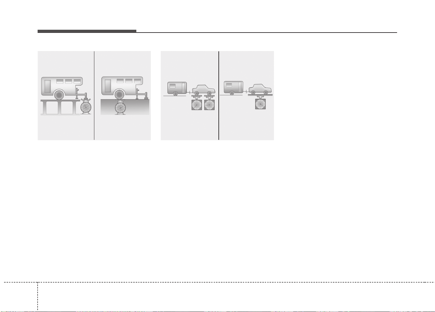
Driving your vehicle
985
Weight of the trailer
What is the maximum safe weight of a
trailer? It should never weigh more than
the maximum trailer weight with trailer
brakes. But even that can be too heavy.
It depends on how you plan to use your
trailer. For example, speed, altitude, road
grades, outside temperature and how
often your vehicle is used to pull a trailer
are all important. The ideal trailer weight
can also depend on any special equip-
ment that you have on your vehicle.
Weight of the trailer tongue
The tongue load of any trailer is an
important weight to measure because it
affects the total gross vehicle weight
(GVW) of your vehicle. This weight
includes the curb weight of the vehicle,
any cargo you may carry in it, and the
people who will be riding in the vehicle.
And if you will tow a trailer, you must add
the tongue load to the GVW because
your vehicle will also be carrying that
weight.
The trailer tongue should weigh a maxi-
mum of 10% of the total loaded trailer
weight, within the limits of the maximum
permissible trailer tongue load. After
you've loaded your trailer, weigh the trail-
er and then the tongue, separately, to
see if the weights are proper. If they
aren’t, you may be able to correct them
simply by moving some items around in
the trailer.
C190E02JM
Gross Axle Weight
Gross Vehicle Weight
C190E01JM
Tongue Load Total Trailer Weight

599
Driving your vehicle
✽✽
NOTICE
With increasing altitude the engine per-
formance decreases. From 1.000 m
above sea level and for every 1.000 m
thereafter 10% of vehicle/trailer weight
(trailer weighter + gross vehicle weight)
must be deducted.
WARNING - Trailer
• Never load a trailer with more
weight in the rear than in the
front. The front should be loaded
with approximately 60% of the
total trailer load; the rear should
be loaded with approximately
40% of the total trailer load.
• Never exceed the maximum
weight limits of the trailer or trail-
er towing equipment. Improper
loading can result in damage to
your vehicle and/or personal
injury. Check weights and loading
at a commercial scale or highway
patrol office equipped with
scales.
• An improperly loaded trailer can
cause loss of vehicle control.
This chapter will guide you in the proper
loading of your vehicle and/or trailer, to
keep your loaded vehicle weight within its
design rating capability, with or without a
trailer. Properly loading your vehicle will
provide maximum return of the vehicle
design performance. Before loading your
vehicle, familiarize yourself with the fol-
lowing terms for determining your vehi-
cle's weight ratings, with or without a
trailer, from the vehicle's specifications
and the certification label:
Base curb weight
This is the weight of the vehicle including
a full tank of fuel and all standard equip-
ment. It does not include passengers,
cargo, or optional equipment.
Vehicle curb weight
This is the weight of your new vehicle
when you picked it up from your dealer
plus any aftermarket equipment.
Cargo weight
This figure includes all weight added to
the Base Curb Weight, including cargo
and optional equipment.
GAW (Gross axle weight)
This is the total weight placed on each
axle (front and rear) - including vehicle
curb weight and all payload.
GAWR (Gross axle weight rating)
This is the maximum allowable weight
that can be carried by a single axle (front
or rear). These numbers are shown on
the certification label.
The total load on each axle must never
exceed its GAWR.
GVW (Gross vehicle weight)
This is the Base Curb Weight plus actual
Cargo Weight plus passengers.
GVWR (Gross vehicle weight rat-
ing)
This is the maximum allowable weight of
the fully loaded vehicle (including all
options, equipment, passengers and
cargo). The GVWR is shown on the cer-
tification label.
Overloading
VEHICLE WEIGHT
5100
Driving your vehicle
WARNING - Vehicle weight
The gross axle weight rating
(GAWR) and the gross vehicle
weight rating (GVWR) for your vehi-
cle are on the certification label
attached to the driver's (or front
passenger’s) door. Exceeding
these ratings can cause an acci-
dent or vehicle damage. You can
calculate the weight of your load by
weighing the items (and people)
before putting them in the vehicle.
Be careful not to overload your
vehicle.

What to do in an emergency
Road warning . . . . . . . . . . . . . . . . . . . . . . . . . . . . . . 6-2
• Hazard warning flasher . . . . . . . . . . . . . . . . . . . . . . . . 6-2
In case of an emergency while driving. . . . . . . . . . 6-3
• If the engine stalls at a crossroad or crossing. . . . . . . 6-3
• If you have a flat tire while driving. . . . . . . . . . . . . . . 6-3
• If engine stalls while driving . . . . . . . . . . . . . . . . . . . . 6-3
If the engine will not start . . . . . . . . . . . . . . . . . . . . 6-4
• If engine doesn’t turn over or turns over slowly . . . . 6-4
• If engine turns over normally but does not start . . . . 6-4
Emergency starting . . . . . . . . . . . . . . . . . . . . . . . . . 6-5
• Jump starting. . . . . . . . . . . . . . . . . . . . . . . . . . . . . . . . . 6-5
• Push-starting . . . . . . . . . . . . . . . . . . . . . . . . . . . . . . . . . 6-7
If the engine overheats. . . . . . . . . . . . . . . . . . . . . . . 6-8
If you have a flat tire (with spare tire). . . . . . . . . . 6-9
• Jack and tools . . . . . . . . . . . . . . . . . . . . . . . . . . . . . . . . 6-9
• Removing and storing the spare tire . . . . . . . . . . . . . 6-10
• Changing tires . . . . . . . . . . . . . . . . . . . . . . . . . . . . . . . 6-10
• Wheel nut tightening torque . . . . . . . . . . . . . . . . . . . 6-14
• Jack label . . . . . . . . . . . . . . . . . . . . . . . . . . . . . . . . . . . 6-17
• EC Declaration of Conformity for Jack . . . . . . . . . . 6-18
If you have a flat tire
(with Tire Mobility Kit). . . . . . . . . . . . . . . . . . . . 6-19
• For 15, 16 inch tire . . . . . . . . . . . . . . . . . . . . . . . . . . . 6-19
• For 17, 18 inch tire . . . . . . . . . . . . . . . . . . . . . . . . . . . 6-27
Tire Pressure Monitoring System (TPMS) . . . . . 6-30
• Changing a tire with TPMS . . . . . . . . . . . . . . . . . . . . 6-33
Towing . . . . . . . . . . . . . . . . . . . . . . . . . . . . . . . . . . . 6-36
• Towing service . . . . . . . . . . . . . . . . . . . . . . . . . . . . . . . 6-36
• Removable towing hook . . . . . . . . . . . . . . . . . . . . . . . 6-37
• Emergency towing . . . . . . . . . . . . . . . . . . . . . . . . . . . . 6-37
Emergency commodity . . . . . . . . . . . . . . . . . . . . . 6-40
• Fire extinguisher . . . . . . . . . . . . . . . . . . . . . . . . . . . . . 6-40
• First aid kit. . . . . . . . . . . . . . . . . . . . . . . . . . . . . . . . . . 6-40
• Triangle reflector. . . . . . . . . . . . . . . . . . . . . . . . . . . . . 6-40
• Tire pressure gauge . . . . . . . . . . . . . . . . . . . . . . . . . . . 6-40
6
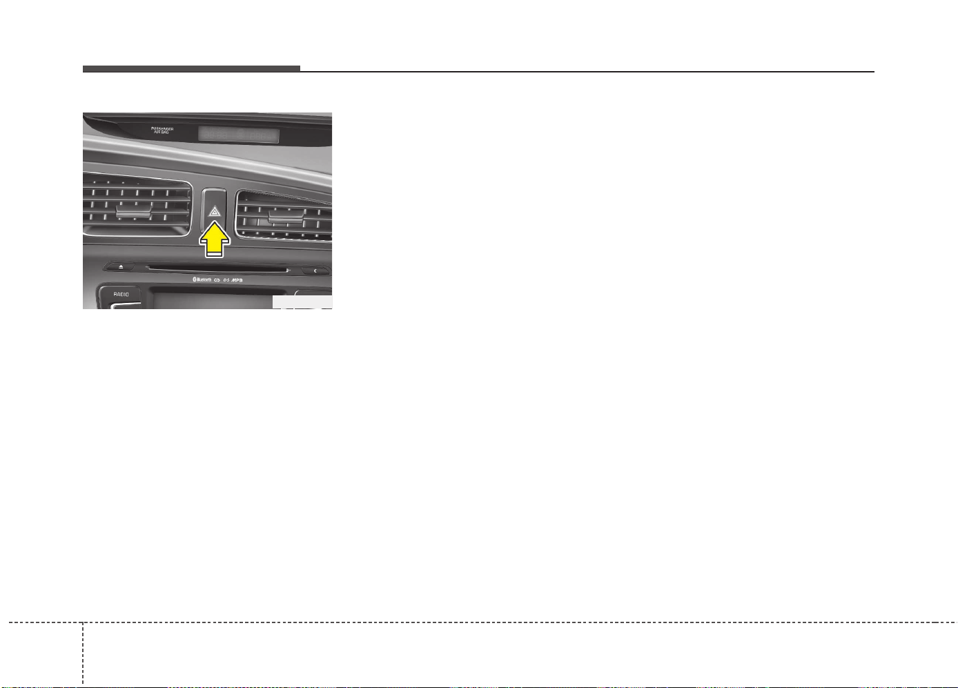
What to do in an emergency
26
ROAD WARNING
Hazard warning flasher
The hazard warning flasher serves as a
warning to other drivers to exercise
extreme caution when approaching,
overtaking, or passing your vehicle.
It should be used whenever emergency
repairs are being made or when the vehi-
cle is stopped near the edge of a road-
way.
Press the flasher switch with the ignition
switch in any position. The flasher switch
is located in the center facia switch
panel. All turn signal lights will flash
simultaneously.
• The hazard warning flasher operates
whether your vehicle is running or not.
• The turn signals do not work when the
hazard flasher is on.
• The hazard warning flasher should
always be on while the vehicle is being
towed.
OJD042089

63
What to do in an emergency
IN CASE OF AN EMERGENCY WHILE DRIVING
If the engine stalls at a crossroad
or crossing
• If the engine stalls at a crossroad or
crossing, set the shift lever in the N
(Neutral) position and then push the
vehicle to a safe place.
• If your vehicle has a manual transaxle
not equipped with a ignition lock
switch, the vehicle can move forward
by shifting to the 2(Second) or 3(Third)
gear and then turning the starter with-
out depressing the clutch pedal.
If you have a flat tire while driving
If a tire goes flat while you are driving:
1.Take your foot off the accelerator pedal
and let the vehicle slow down while
driving straight ahead. Do not apply the
brakes immediately or attempt to pull
off the road as this may cause a loss of
control. When the vehicle has slowed
to such a speed that it is safe to do so,
brake carefully and pull off the road.
Drive off the road as far as possible
and park on firm, level ground. If you
are on a divided highway, do not park
in the median area between the two
traffic lanes.
2.When the vehicle is stopped, turn on
your emergency hazard flashers, set
the parking brake and put the transaxle
in P (automatic transaxle) or reverse
(manual transaxle).
3.Have all passengers get out of the
vehicle. Be sure they all get out on the
side of the vehicle that is away from
traffic.
4.When changing a flat tire, follow the
instruction provided later in this chap-
ter.
If engine stalls while driving
1. Reduce your speed gradually, keeping
a straight line. Move cautiously off the
road to a safe place.
2. Turn on your emergency flashers.
3. Try to start the engine again. If your
vehicle does not start, we recommend
that you consult an authorized Kia
dealer.
What to do in an emergency
46
IF THE ENGINE WILL NOT START
If engine doesn't turn over or
turns over slowly
1. If your vehicle has an automatic
transaxle, be sure the shift lever is in N
(Neutral) or P (Park) and the emer-
gency brake is set.
2. Check the battery connections to be
sure they are clean and tight.
3. Turn on the interior light. If the light
dims or goes out when you operate the
starter, the battery is discharged.
4. Check the starter connections to be
sure they are securely tightened.
5. Do not push or pull the vehicle to start
it. See instructions for "Jump starting".
If engine turns over normally but
does not start
1. Check fuel level.
2. With the ignition switch in the LOCK/
OFF position, check all connectors at
ignition, coil and spark plugs.
Reconnect any that may be discon-
nected or loose.
3. Check the fuel line in the engine com-
partment.
4. If the engine still does not start, we
recommend that you call an author-
ized Kia dealer.
WARNING
If the engine does not start, do not
push or pull the vehicle to start it.
This could result in a collision or
cause other damage. In addition,
push or pull starting may cause the
catalytic converter (if equipped) to
be overloaded and create a fire haz-
ard.
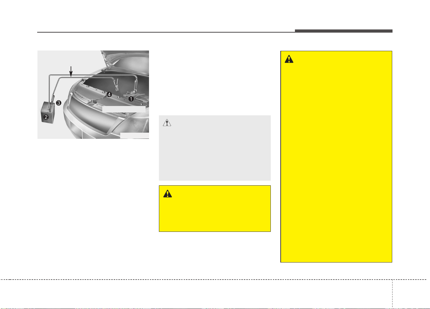
65
What to do in an emergency
EMERGENCY STARTING
Connect cables in numerical order and
disconnect in reverse order.
Jump starting
Jump starting can be dangerous if done
incorrectly. Therefore, to avoid harm to
yourself or damage to your vehicle or
battery, follow the jump starting proce-
dures. If in doubt, we strongly recom-
mend that you have a competent techni-
cian or towing service jump start your
vehicle.
CAUTION
Use only a 12-volt jumper system.
You can damage a 12-volt starting
motor, ignition system, and other
electrical parts beyond repair by
use of a 24-volt power supply (either
two 12-volt batteries in series or a
24-volt motor generator set).
WARNING - Battery
• Keep all flames or sparks away
from the battery. The battery pro-
duces hydrogen gas which may
explode if exposed to flame or
sparks.
If these instructions are not fol-
lowed exactly, serious personal
injury and damage to the vehicle
may occur! If you are not sure how
to follow this procedure, seek
qualified assistance. Automobile
batteries contain sulfuric acid.
This is poisonous and highly cor-
rosive. When jump starting, wear
protective glasses and be careful
not to get acid on yourself, your
clothing or on the vehicle.
• Do not attempt to jump start the
vehicle if the discharged battery
is frozen or if the electrolyte level
is low; the battery may rupture or
explode.
• Do not allow the (+) and (-)
jumper cables to touch. It may
cause sparks.
• The battery may rupture or
explode when you jump start with
a low or frozen battery.
WARNING - Battery
Never attempt to check the elec-
trolyte level of the battery as this
may cause the battery to rupture or
explode causing serious injury.
1VQA4001
Discharged battery
Jumper Cables
■ Engine compartment
Booster battery
(-)
(+)
(+)
(-)

What to do in an emergency
66
Jump starting procedure
✽✽
NOTICE
If the battery is discharged, the engine
can be started using a battery of anoth-
er vehicle and two jumper cables. Only
use jumper cables with fully insulated
clamp handles.
To prevent personal injury or damage to
both vehicles, adhere strictly to the fol-
lowing procedure.
1. Make sure the booster battery is 12-
volt and that its negative terminal is
grounded.
2. If the booster battery is in another
vehicle, do not allow the vehicles to
touch.
3. Turn off all unnecessary electrical
loads.
4. Connect the jumper cables in the exact
sequence shown in the illustration.
First connect one end of a jumper
cable to the positive terminal of the
discharged battery (1), then connect
the other end to the positive terminal
on the booster battery (2). Proceed to
connect one end of the other jumper
cable to the negative terminal of the
booster battery (3), then the other end
to a solid, stationary, metallic point (for
example, the engine lifting bracket)
away from the battery (4). Do not con-
nect it to or near any part that moves
when the engine is cranked. Make
sure that there is no contact between
the bodywork of the two vehicles; oth-
erwise, there is the danger of short cir-
cuits.
Do not allow the jumper cables to con-
tact anything except the correct battery
terminals or the correct ground. Do not
lean over the battery when making
connections.
CAUTION - AGM battery
(if equipped)
• Absorbent Glass Matt (AGM) bat-
teries are maintenance-free and
we recommend that the AGM bat-
teries be serviced by an author-
ized Kia dealer. For charging your
AGM battery, use only fully auto-
matic battery chargers that are
specially developed for AGM bat-
teries.
• When replacing the AGM battery,
we recommend that you use parts
for replacement from an author-
ized Kia dealer.
• Do not open or remove the cap on
top of the battery. This may cause
leaks of internal electrolyte that
could result in severe injury.
• If the AGM battery is reconnected
or replaced, ISG function will not
operate immediately.
If you want to use the ISG func-
tion, the battery sensor needs to
be calibrated for approximately 4
hours with the ignition off.
67
What to do in an emergency
5. Start the engine of the vehicle with the
booster battery and let it run at 2,000
rpm, then start the engine of the vehi-
cle with the discharged battery. If the
first starting attempt is not successful,
wait a few minutes before making
another attempt in order to allow the
discharged battery to recharge.
If the cause of your battery discharging is
not apparent, we recommend that the
system be checked by an authorized Kia
dealer.
Push-starting
Your manual transaxle-equipped vehicle
should not be push-started because it
might damage the emission control sys-
tem. Vehicles equipped with automatic
transaxle cannot be push-started. Follow
the directions in this chapter for “Jump-
starting”.
WARNING
Never tow a vehicle to start it
because the sudden surge forward
when the engine starts could cause
a collision with the tow vehicle.
CAUTION - Battery cables
Do not connect the jumper cable
from the negative terminal of the
booster battery to the negative ter-
minal of the discharged battery.
This can cause the discharged bat-
tery to overheat and crack, releas-
ing battery acid.
Make sure to connect one end of
the jumper cable to the negative ter-
minal of the booster battery, and the
other end to a metallic point, far
away from the battery.
What to do in an emergency
86
IF THE ENGINE OVERHEATS
If your temperature gauge indicates over-
heating, you will experience a loss of
power, or hear loud pinging or knocking,
the engine is probably too hot. If this hap-
pens, you should:
1. Pull off the road and stop as soon as it
is safe to do so.
2. Place the shift lever in P (automatic
transaxle) or neutral (manual
transaxle) and set the parking brake. If
the air conditioning is on, turn it off.
3. If engine coolant is running out under
the vehicle or steam is coming out
from the hood, stop the engine. Do not
open the hood until the coolant has
stopped running or the steaming has
stopped. If there is no visible loss of
engine coolant and no steam, leave
the engine running and check to be
sure the engine cooling fan is operat-
ing. If the fan is not running, turn the
engine off.
4. Check to see if the water pump drive
belt is missing. If it is not missing,
check to see that it is tight. If the drive
belt seems to be satisfactory, check
for coolant leaking from the radiator,
hoses or under the vehicle. (If the air
conditioning had been in use, it is nor-
mal for cold water to be draining from
it when you stop).
5. If the water pump drive belt is broken
or engine coolant is leaking out, stop
the engine immediately and we recom-
mend that you call an authorized Kia
dealer.
6.If you cannot find the cause of the
overheating, wait until the engine tem-
perature has returned to normal. Then,
if coolant has been lost, carefully add
coolant to the reservoir to bring the
fluid level in the reservoir up to the
halfway mark.
7.Proceed with caution, keeping alert for
further signs of overheating. If over-
heating happens again, we recom-
mend that you call an authorized Kia
dealer.
CAUTION
Serious loss of coolant indicates
there is a leak in the cooling system
and we recommend that the system
be checked by an authorized Kia
dealer.
WARNING
While the engine is running, keep
hair, hands and clothing away from
moving parts such as the fan and
drive belts to prevent injury.
WARNING
Do not remove the radiator cap
when the engine is hot. This can
allow coolant to blow out of the
opening and cause serious burns.
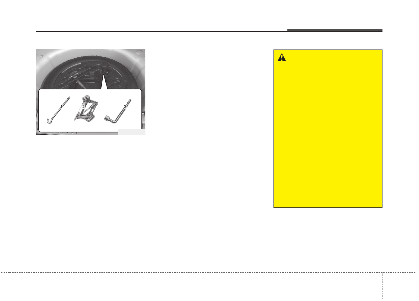
69
What to do in an emergency
IF YOU HAVE A FLAT TIRE (WITH SPARE TIRE, IF EQUIPPED)
Jack and tools
The jack, jack handle, wheel lug nut
wrench are stored in the luggage
compartment.
Pull up the luggage box cover to
reach this equipment.
(1) Jack handle
(2) Jack
(3) Wheel lug nut wrench
Jacking instructions
The jack is provided for emergency
tire changing only.
To prevent the jack from “rattling”
while the vehicle is in motion, store it
properly and fasten the jack screw
fully.
Follow jacking instructions to reduce
the possibility of personal injury.
OJD062001
WARNING - Changing tires
• Never attempt vehicle repairs
in the traffic lanes of a public
road or highway.
• Always move the vehicle com-
pletely off the road and onto
the shoulder before trying to
change a tire. The jack should
be used on firm level ground.
If you cannot find a firm level
place off the road, call a tow-
ing service company for
assistance.
• Be sure to use the correct
front and rear jacking posi-
tions on the vehicle; never
use the bumpers or any other
part of the vehicle for jacking
support.
(Continued)
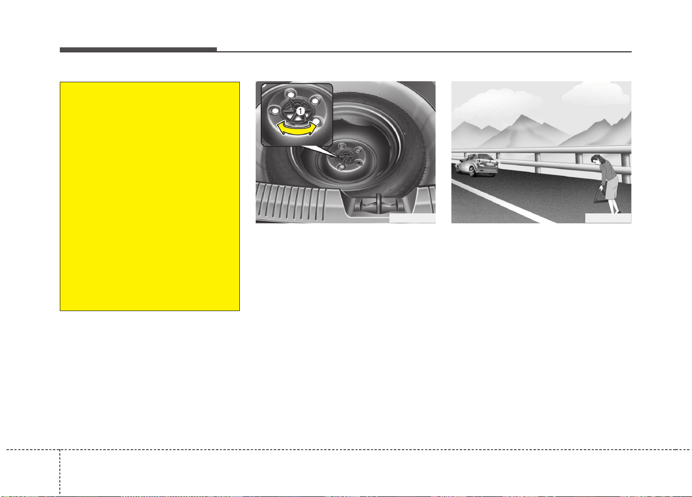
What to do in an emergency
106
Removing and storing the spare
tire
Turn the tire hold-down wing bolt (1)
counterclockwise.
Store the tire in the reverse order of
removal.
To prevent the spare tire and tools
from “rattling” while the vehicle is in
motion, store them properly.
Changing tires
1. Park on a level surface and apply
the parking brake firmly.
2. Shift the shift lever into R
(Reverse) with manual transaxle
or P (Park) with automatic
transaxle.
3. Activate the hazard warning flash-
er.
OGD061004
(Continued)
• The vehicle can easily roll off
the jack causing serious
injury or death.
• Do not get under a vehicle
that is supported by a jack.
• Do not start or run the engine
while the vehicle is on the
jack.
• Do not allow anyone to remain
in the vehicle while it is on the
jack.
• Make sure any children pres-
ent are in a secure place away
from the road and from the
vehicle to be raised with the
jack.
OED066033
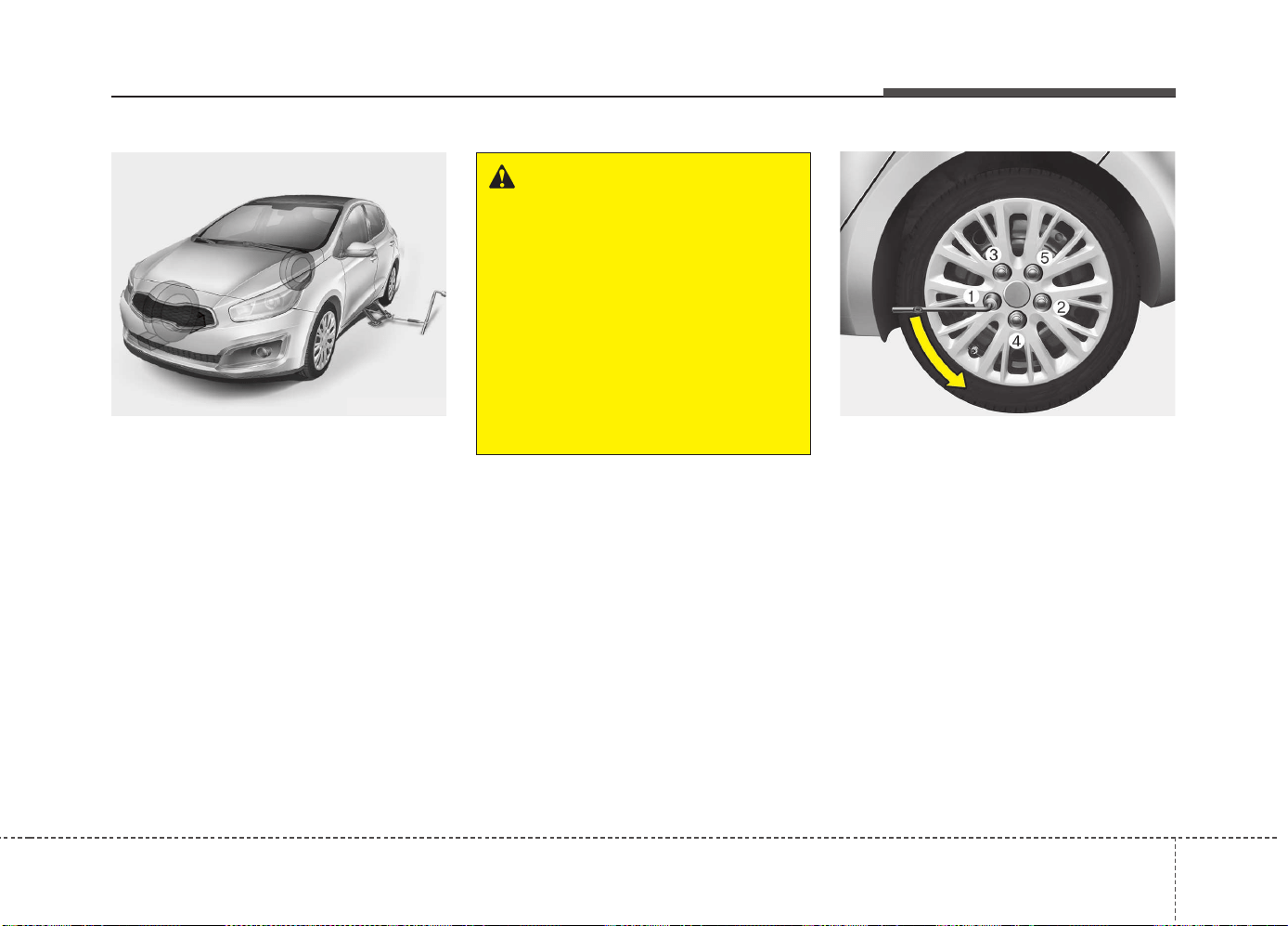
611
What to do in an emergency
4. Remove the wheel lug nut wrench,
jack, jack handle, and spare tire
from the vehicle.
5. Block both the front and rear of the
wheel that is diagonally opposite
the jack position.
6. Loosen the wheel lug nuts coun-
terclockwise one turn each, but do
not remove any nut until the tire
has been raised off the ground.
WARNING -
Changing a tire
• To prevent vehicle movement
while changing a tire, always
set the parking brake fully,
and always block the wheel
diagonally opposite the wheel
being changed.
• We recommend that the
wheels of the vehicle be
chocked, and that no person
remain in a vehicle that is
being jacked.
OJD065003
OJD065004
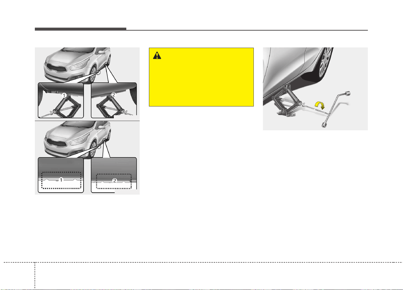
What to do in an emergency
126
7. Place the jack at the front (1) or
rear (2) jacking position closest to
the tire you are changing. Place
the jack at the designated loca-
tions under the frame. The jacking
positions are plates welded to the
frame with two tabs and a raised
dot to index with the jack.
8. Insert the jack handle into the jack
and turn it clockwise, raising the
vehicle until the tire just clears the
ground. This measurement is
approximately 30 mm (1.2 in).
Before removing the wheel lug
nuts, make sure the vehicle is sta-
ble and that there is no chance for
movement or slippage.
WARNING - Jack location
To reduce the possibility of
injury, be sure to use only the
jack provided with the vehicle
and in the correct jack position;
never use any other part of the
vehicle for jack support.
OJD065016
OJD065018
OJD065019
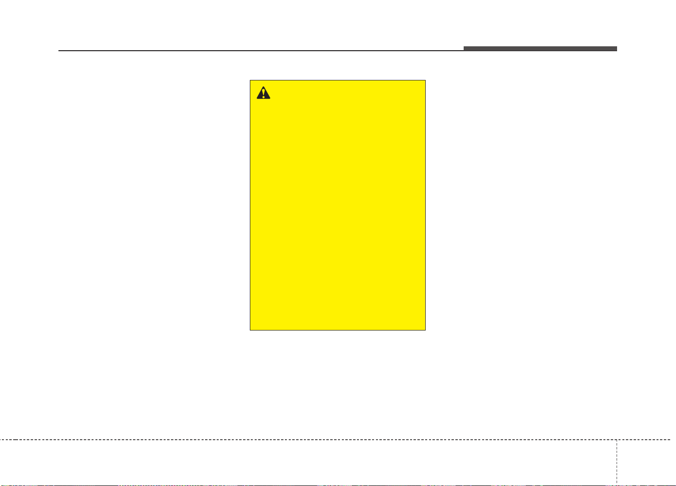
613
What to do in an emergency
9. Loosen the wheel nuts and
remove them with your fingers.
Slide the wheel off the studs and
lay it flat so it cannot roll away. To
put the wheel on the hub, pick up
the spare tire, line up the holes
with the studs and slide the wheel
onto them. If this is difficult, tip the
wheel slightly and get the top hole
in the wheel lined up with the top
stud. Then jiggle the wheel back
and forth until the wheel can be
slid over the other studs.
10. To reinstall the wheel, hold it on
the studs, put the wheel nuts on
the studs and tighten them finger
tight. The nuts should be installed
with their tapered small diameter
ends directed inward. Jiggle the
tire to be sure it is completely
seated, then tighten the nuts as
much as possible with your fin-
gers again.
11. Lower the vehicle to the ground
by turning the wheel nut wrench
counterclockwise.
WARNING
• Wheels and wheel covers may
have sharp edges. Handle
them carefully to avoid possi-
ble severe injury.
• Before putting the wheel into
place, be sure that there is
nothing on the hub or wheel
(such as mud, tar, gravel, etc.)
that interferes with the wheel
from fitting solidly against the
hub. If there is, remove it. If the
contact of the mounting sur-
face between the wheel and
hub is not good, the wheel
nuts could come loose and
cause loss of a wheel. Loss of
a wheel may result in losing
control of the vehicle. This may
cause serious injury or death.
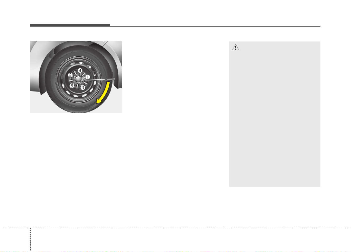
What to do in an emergency
146
Then position the wrench as shown
in the drawing and tighten the wheel
nuts. Be sure the socket is seated
completely over the nut. Do not stand
on the wrench handle or use an
extension pipe over the wrench han-
dle. Go around the wheel tightening
every nut following the numerical
sequence shown in the image until
they are all tight. Then double-check
each nut for tightness. After changing
wheels, we recommend that the sys-
tem be checked by an authorized Kia
dealer.
Wheel nut tightening torque:
Steel wheel & aluminium alloy wheel:
9~11 kgf·m (65~79 lbf·ft)
If you have a tire gauge, remove the
valve cap and check the air pressure.
If the pressure is lower than recom-
mended, drive slowly to the nearest
service station and inflate to the cor-
rect pressure. If it is too high, adjust it
until it is correct. Always reinstall the
valve cap after checking or adjusting
tire pressure. If the cap is not
replaced, air may leak from the tire. If
you lose a valve cap, buy another and
install it as soon as possible.
After you have changed wheels,
always secure the flat tire in its place
and return the jack and tools to their
proper storage locations.
CAUTION
Your vehicle has metric threads
on the wheel studs and nuts.
Make certain during wheel
removal that the same nuts that
were removed are reinstalled -
or, if replaced, that nuts with
metric threads and the same
chamfer configuration are used.
Installation of a non-metric
thread nut on a metric stud or
vice-versa will not secure the
wheel to the hub properly and
will damage the stud so that it
must be replaced.
Note that most lug nuts do not
have metric threads. Be sure to
use extreme care in checking
for thread style before installing
aftermarket lug nuts or wheels.
If in doubt, we recommend that
you consult an authorized Kia
dealer.
OGD061013
615
What to do in an emergency
To prevent the jack, jack handle,
wheel lug nut wrench and spare tire
from rattling while the vehicle is in
motion, store them properly.
Important - use of compact spare tire
(if equipped)
Your vehicle is equipped with a com-
pact spare tire. This compact spare
tire takes up less space than a regu-
lar-size tire. This tire is smaller than a
conventional tire and is designed for
temporary use only.
The compact spare should be inflat-
ed to 420 kPa (60 psi).
✽✽
NOTICE
Check the inflation pressure after
installing the spare tire. Adjust it to
the specified pressure, as necessary.
CAUTION
• You should drive carefully
when the compact spare is in
use. The compact spare
should be replaced by the
proper conventional tire and
rim at the first opportunity.
• The operation of this vehicle
is not recommended with
more than one compact spare
tire in use at the same time.
WARNING
The compact spare tire is for
emergency use only. Do not
operate your vehicle on this
compact spare at the speed
over 80 km/h (50 mph).The orig-
inal tire should be repaired or
replaced as soon as possible to
avoid failure of the spare possi-
bly leading to personal injury or
death.
WARNING - Wheel studs
If the studs are damaged, they
may lose their ability to retain
the wheel. This could lead to the
loss of the wheel and a collision
resulting in serious injuries.
WARNING - Inadequate
spare tire pressure
Check the inflation pressures as
soon as possible after installing
the spare tire. Adjust it to the
specified pressure, if necessary.
Refer to “Tires and wheels” in
chapter 8.

What to do in an emergency
166
When using a compact spare tire,
observe the following precautions:
• Under no circumstances should
you exceed 80 km/h (50 mph); a
higher speed could damage the
tire.
• Ensure that you drive slowly
enough to avoid all hazards. Any
road hazard, such as a pothole or
debris, could seriously damage the
compact spare.
• Any continuous road use of this tire
could result in tire failure, loss of
vehicle control, and possible per-
sonal injury.
• Do not exceed the vehicle’s maxi-
mum load rating or the load-carry-
ing capacity shown on the sidewall
of the compact spare tire.
• Avoid driving over obstacles. The
compact spare tire diameter is
smaller than the diameter of a con-
ventional tire and reduces the
ground clearance approximately
25 mm (1 inch), which could result
in damage to the vehicle.
• Do not take this vehicle through an
automatic car wash while the com-
pact spare tire is installed.
• Do not use tire chains on the com-
pact spare tire. Because of the
smaller size, a tire chain will not fit
properly. This could damage the
vehicle and result in loss of the
chain.
• The compact spare tire should not
be installed on the front axle if the
vehicle must be driven in snow or
on ice.
• Do not use the compact spare tire
on any other vehicle because this
tire has been designed especially
for your vehicle.
• The compact spare tire’s tread life
is shorter than a regular tire.
Inspect your compact spare tire
regularly and replace worn com-
pact spare tires with the same size
and design, mounted on the same
wheel.
• The compact spare tire should not
be used on any other wheels, nor
should standard tires, snow tires,
wheel covers or trim rings be used
with the compact spare wheel. If
such use is attempted, damage to
these items or other car compo-
nents may occur.
• Do not use more than one compact
spare tire at a time.
• Do not tow a trailer while the com-
pact spare tire is installed.
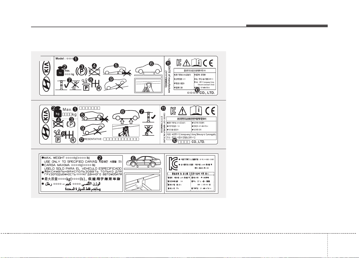
617
What to do in an emergency
Jack label 1. Model Name
2. Maximum allowable load
3. When using the jack, set your
parking brake.
4. When using the jack, stop the
engine.
5. Do not get under a vehicle that is
supported by a jack.
6. The designated locations under
the frame
7. When supporting the vehicle, the
base plate of jack must be vertical
under the lifting point.
8. Shift into Reverse gear on vehicles
with manual transaxle or move the
shift lever to the P position on
vehicles with automatic transaxle.
9. The jack should be used on firm
level ground.
10. Jack manufacturer
11. Production date
12. Representative company and
address
❈ The actual Jack label in the vehicle may differ from the illustration. For
more detailed specifications, refer to the label attached to the jack.
OHYK064001
OHYK064005
OHYK064002
■ Type A
■ Example
■ Type B
■ Type C
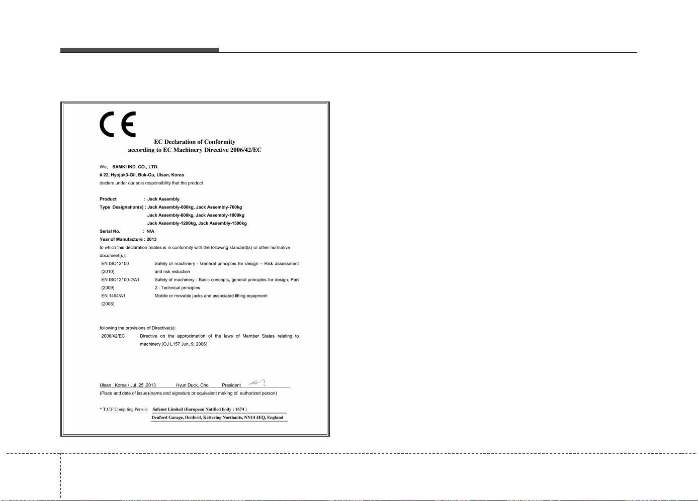
What to do in an emergency
186
EC Declaration of Conformity for Jack
JACKDOC14S
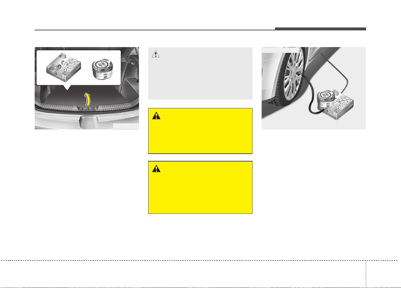
619
What to do in an emergency
IF YOU HAVE A FLAT TIRE (WITH TIRE MOBILITY KIT, IF EQUIPPED)
For 15, 16 inch tire
For safe operation, carefully read
and follow the instructions in this
manual before use.
(1) Compressor
(2) Sealant bottle
The Tire Mobility Kit is a temporary
fix to the tire and we recommend that
the system be inspected by an
authorized Kia dealer.
Introduction
With the Tire Mobility Kit you stay
mobile even after experiencing a tire
puncture.
The system of compressor and seal-
ing compound effectively and com-
fortably seals most punctures in a
passenger car tire caused by nails
or similar objects and reinflates the
tire.
After you ensured that the tire is
properly sealed you can drive cau-
tiously on the tire (distance up to 200
km (120 miles)) at a max. speed of
80 km/h (50 mph) in order to reach a
service station or tire dealer to have
the tire replaced.
WARNING
Have your tire repaired as soon
as possible. The tire may loose
air pressure at any time after
inflating with the Tire Mobility
Kit.
OJD064011 OJD065017
CAUTION
When two or more tires are flat,
do not use the tire mobility kit
because the supported one
sealant of Tire Mobility Kit is only
used for one flat tire.
WARNING
Do not use the Tire Mobility Kit
to repair punctures in the tire
walls. This can result in an acci-
dent due to tire failure.
■ for 15 inch tire
What to do in an emergency
206
It is possible that some tires, espe-
cially with larger punctures or dam-
age to the sidewall, cannot be sealed
completely.
Air pressure loss in the tire may
adversely affect tire performance.
For this reason, you should avoid
abrupt steering or other driving
maneuvers, especially if the vehicle
is heavily loaded or if a trailer is in
use.
The Tire Mobility Kit is not designed
or intended as a permanent tire
repair method and is to be used for
one tire only. This instruction shows
you step by step how to temporarily
seal the puncture simply and reliably.
Read the section “Notes on the safe
use of the Tire Mobility Kit”.
Notes on the safe use of the Tire
Mobility Kit
• Park your car at the side of the
road so that you can work with the
Tire Mobility Kit away from moving
traffic.
• To be sure your vehicle will not
move, even when you're on fairly
level ground, always set your park-
ing brake.
• Only use the Tire Mobility Kit for
sealing/inflation passenger car
tires. Only punctured areas located
within the tread region of the tire
can be sealed using the tire mobil-
ity kit.
• Do not use on motorcycles, bicy-
cles or any other type of tires.
• When the tire and wheel are dam-
aged, do not use Tire Mobility Kit
for your safety.
• Use of the Tire Mobility Kit may not
be effective for tire damage larger
than approximately 6 mm (0.24 in).
If the tire cannot be made roadwor-
thy with the Tire Mobility Kit, we
recommend that you contact an
authorized Kia dealer.
WARNING
Do not use the TMK if a tire is
severely damaged by driving
run flat or with insufficient air
pressure.
Only punctured areas located
within the tread region of the
tire can be sealed using the
TMK.
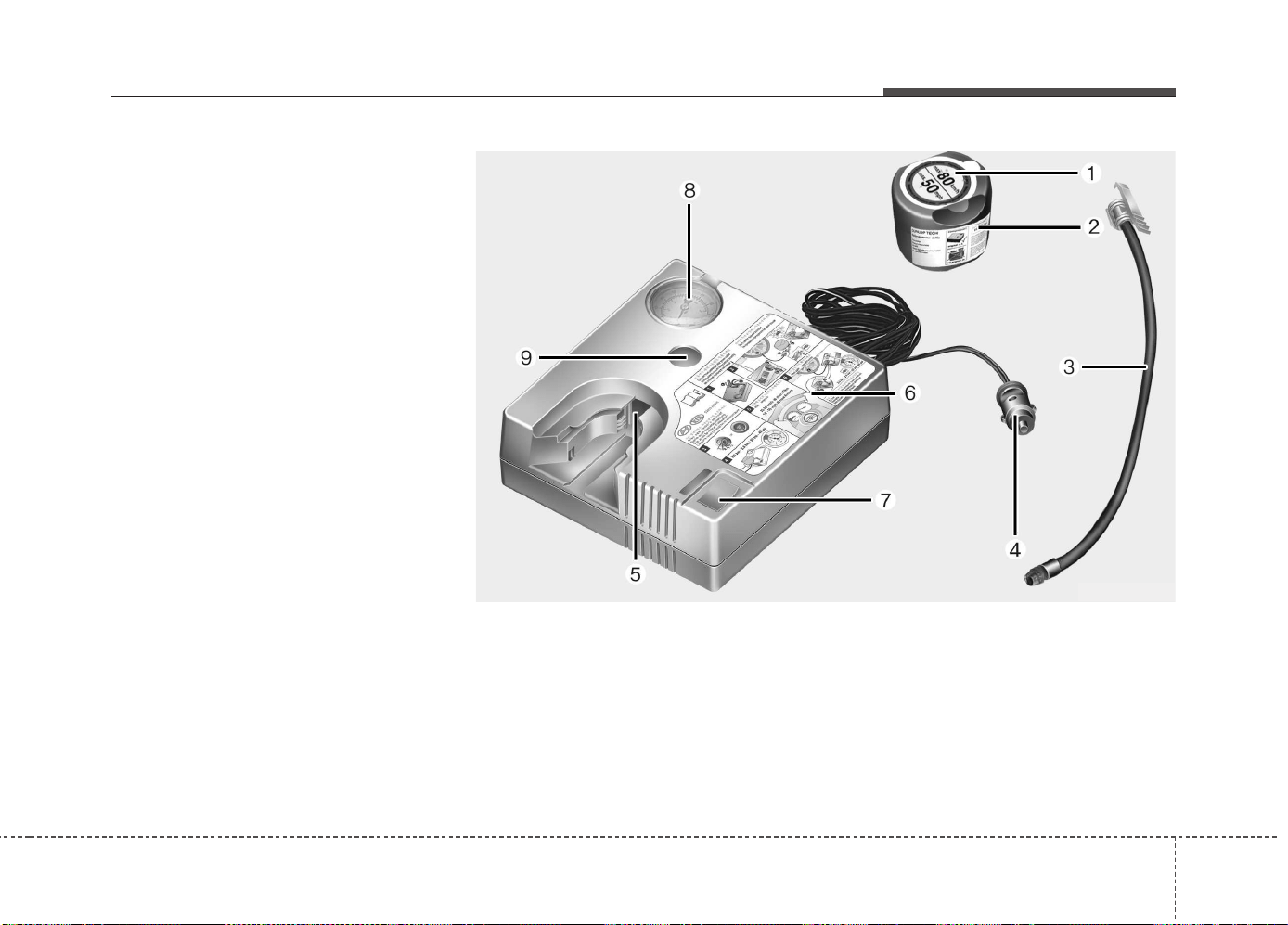
621
What to do in an emergency
• Do not use the Tire Mobility Kit if a
tire is severely damaged by driving
run flat or with insufficient air pres-
sure.
• Do not remove any foreign objects
such as nails or screws that have
penetrated the tire.
• Provided the car is outdoors, leave
the engine running. Otherwise
operating the compressor may
eventually drain the car battery.
• Never leave the Tire Mobility Kit
unattended while it is being used.
• Do not leave the compressor run-
ning for more than 10 min. at a time
or it may overheat.
• Do not use the Tire Mobility Kit if
the ambient temperature is below -
30°C (-22°F).
1. Speed restriction label
2. Sealant bottle and label with
speed restriction
3. Filling hose from sealant bottle to
wheel
4. Connectors and cable for the bat-
tery direct connection
5. Holder for the sealant bottle
6. Compressor
7. On/off switch
8. Pressure gauge for displaying the
tire inflation pressure
9. Button for reducing tire inflation
Pressure
Components of the Tire Mobility Kit
ODE066039L
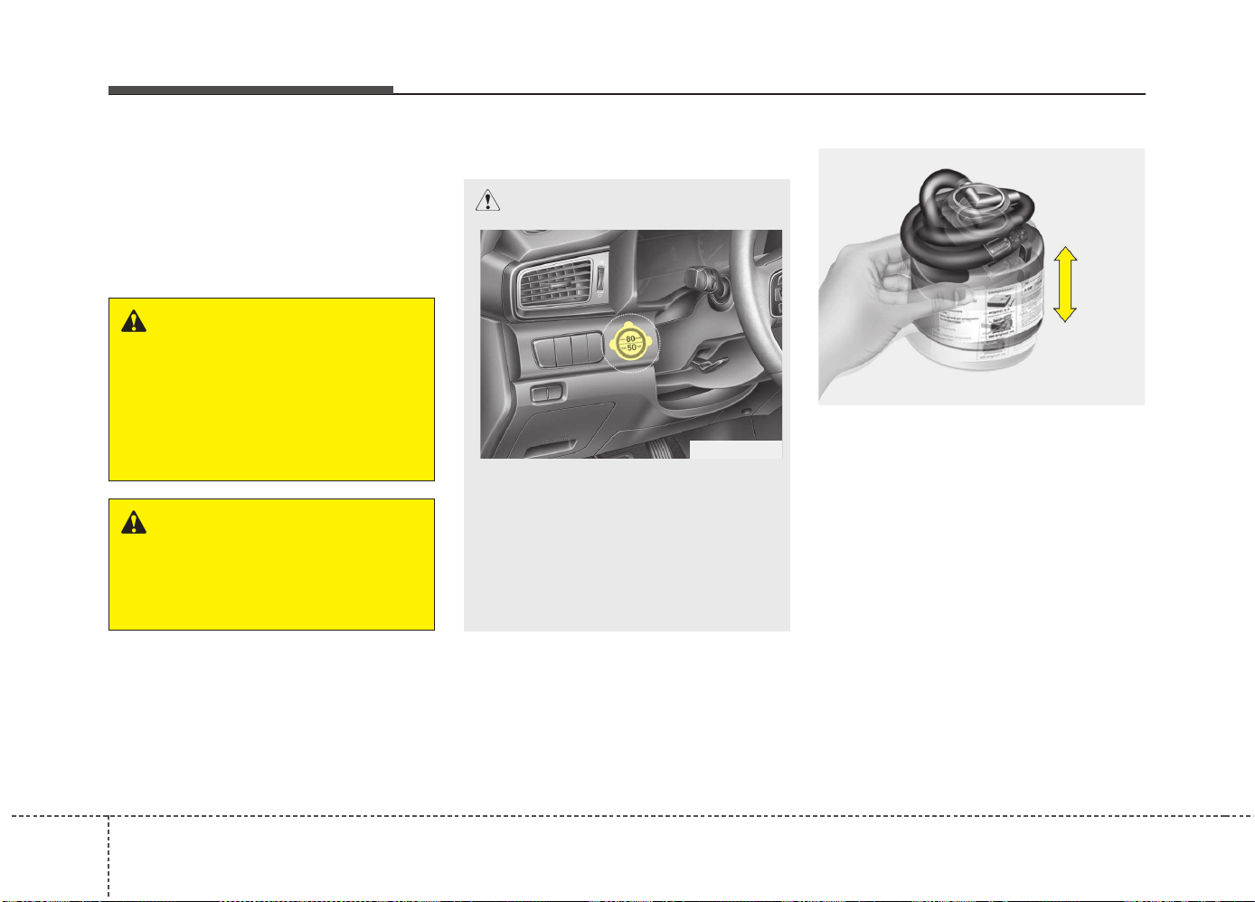
What to do in an emergency
226
Connectors, cable and connection
hose are stored in the compressor
housing.
Strictly follow the specified
sequence, otherwise the sealant
may escape under high pressure.
Using the Tire Mobility Kit
1. Shake the sealant bottle.
WARNING - Expired
sealant
Do not use the Tire sealant after
the sealant has expired (i.e. past-
ed the expiration date on the
sealant container). This can
increase the risk of tire failure.
WARNING - Sealant
• Keep out of reach of children.
• Avoid contact with eyes.
• Do not swallow.
CAUTION
Detach the speed restriction
label (0) from the sealant bottle
(1), and place it in a highly visi-
ble place inside the vehicle
such as on the steering wheel to
remind the driver not to drive
too fast.
ODE066006N
OTAM061022
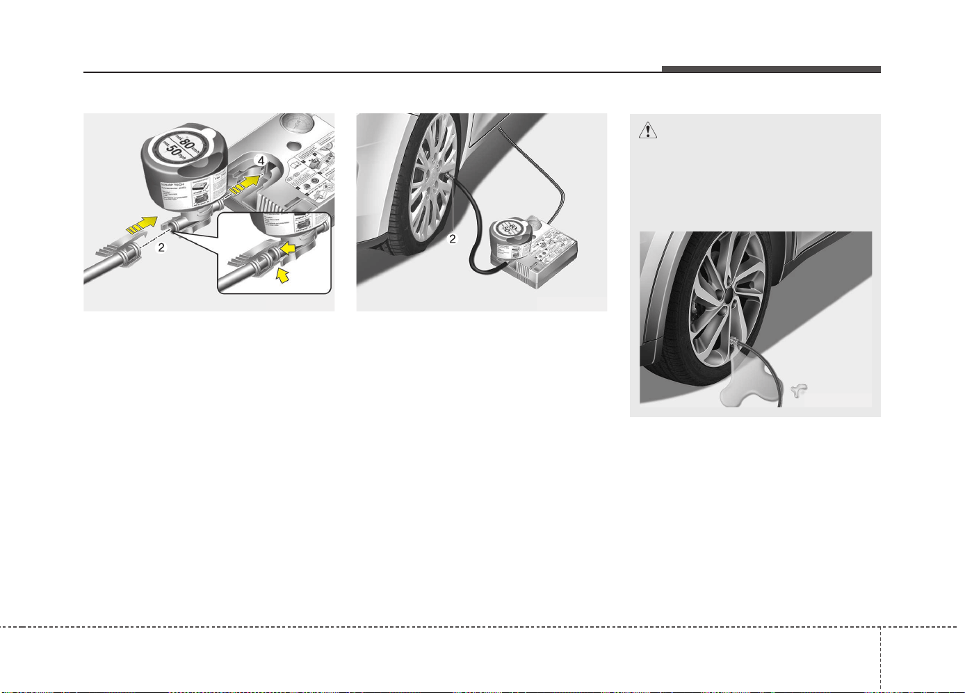
623
What to do in an emergency
2. Screw the filling hose (2) onto the
connector of the sealant bottle (1).
3. Insert the sealant bottle into the
housing of the compressor (4) so
that the bottle is upright.
4. Ensure that the button (9) on the
compressor is not pressed.
5. Unscrew the valve cap from the
valve of the defective wheel and
screw the filling hose (2) of the
sealant bottle onto the valve.
6. Ensure that the compressor is
switched off, position 0.
OJD065017OYN064021
CAUTION
Securely install the sealant fill-
ing hose to the valve. If not,
sealant may flow backward,
possibly clogging the filling
hose.
ODE066041N
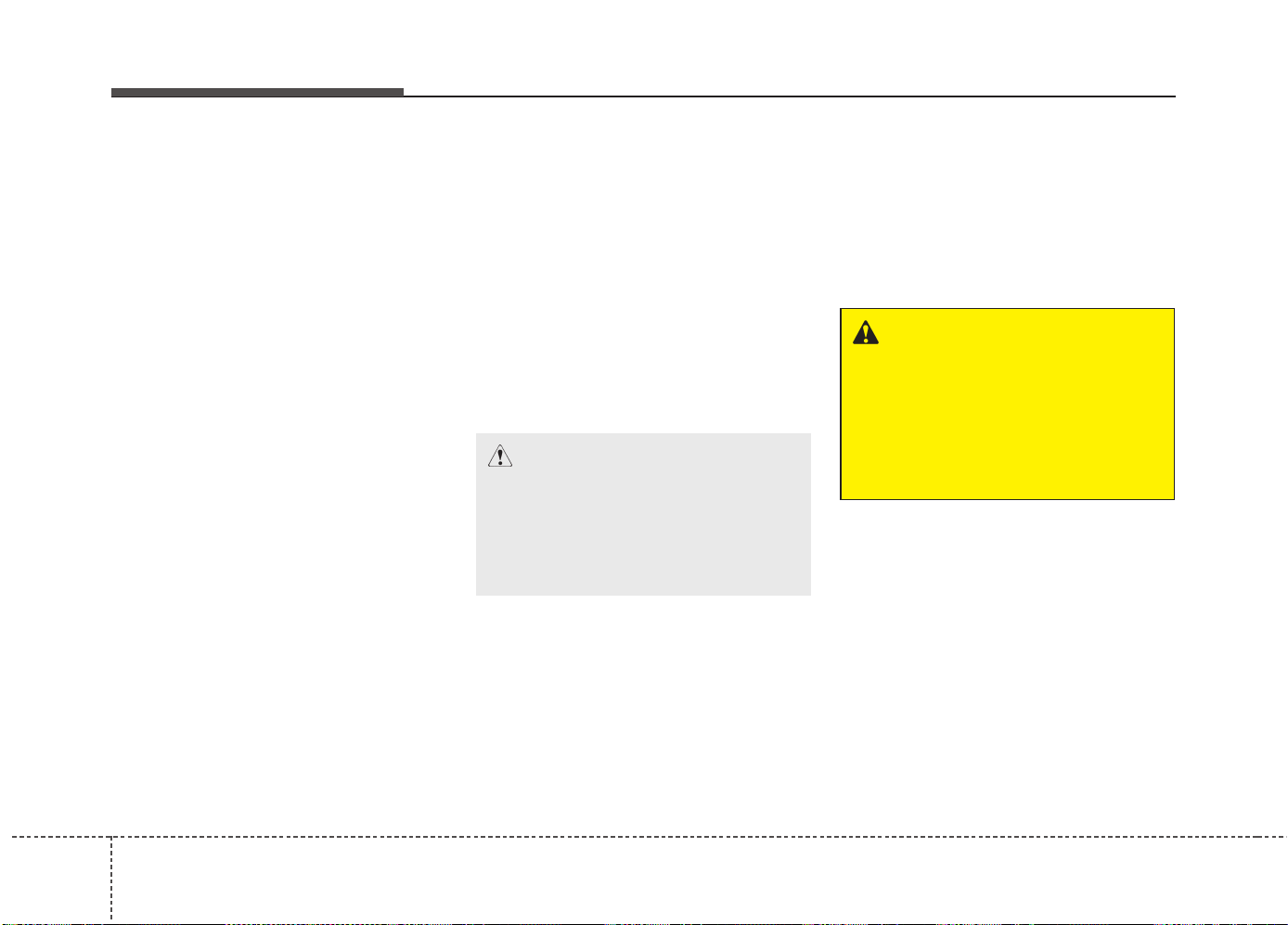
What to do in an emergency
246
7. Plug the compressor power cord
into the vehicle power outlet.
✽✽
NOTICE
Only use the front passenger side
power outlet when connecting the
power cord.
8. With the ignition switch in the ON
position, switch on the compressor
and let it run for approximately 5~7
minutes to fill the sealant up to
proper pressure. (refer to the Tire
and Wheels, chapter 8). The infla-
tion pressure of the tire after filling
is unimportant and will be
checked/corrected later.
Be careful not to overinflate the
tire and stay away from the tire
when filling it.
9. Switch off the compressor.
10. Detach the hoses from the
sealant bottle connector and
from the tire valve.
Return the Tire Mobility Kit to its stor-
age location in the vehicle.
WARNING - Carbon
monoxide
Do not leave your vehicle run-
ning in a poorly ventilated area
for extended periods of time.
Carbon monoxide poisoning
and suffocation can occur.
CAUTION - Tire pressure
Do not attempt to drive your
vehicle if the tire pressure is
below 200 kPa (29 psi). This
could result in an accident due
to sudden tire failure.
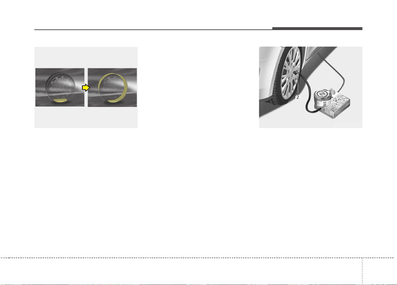
625
What to do in an emergency
Distributing the sealant
11. Immediately drive approximately
7~10 km (4~6 miles or, about
10min) to evenly distribute the
sealant in the tire.
Do not exceed a speed of 80 km/h
(50 mph). If possible, do not fall
below a speed of 20 km/h (12 mph).
While driving, if you experience any
unusual vibration, ride disturbance or
noise, reduce your speed and drive
with caution until you can safely pull
off of the side of the road.
Call for road side service or towing.
When you use the Tire Mobility Kit,
the tire pressure sensors and wheel
may be damaged by sealant, remove
the sealant stained with tire pressure
sensors and wheel and inspect in
authorized dealer.
Checking the tire inflation pressure
1. After driving approximately 7~10
km (4~6 miles or about 10 min),
stop at a safety location.
2. Connect the filling hose (2) of the
compressor directly to the tire
valve.
3. Plug the compressor power cord
into the vehicle power outlet.
4. Adjust the tire inflation pressure to
the recomended tire inflation.
With the ignition swithched on,
proceed as follows.
ODE066040N OJD065017
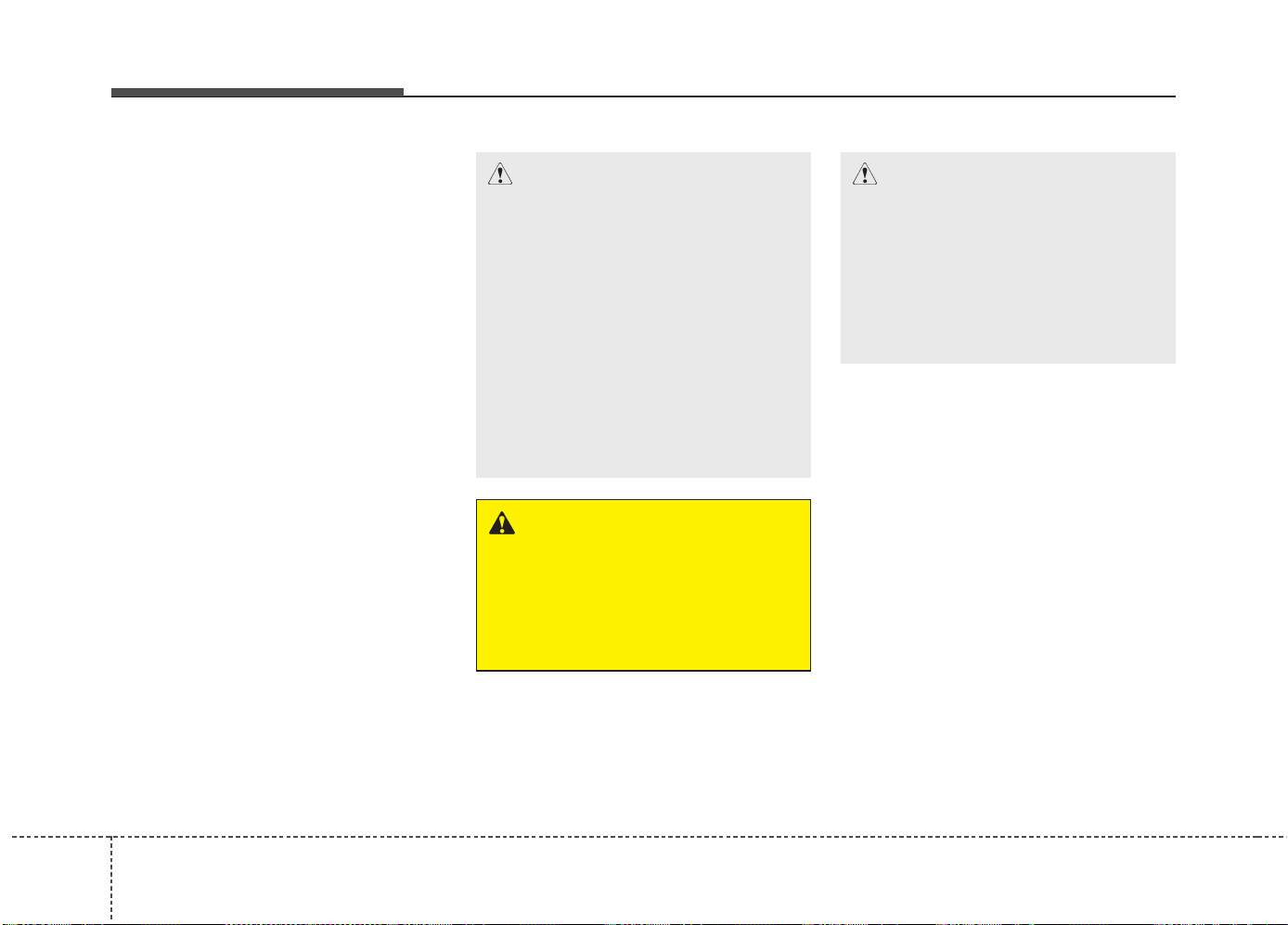
What to do in an emergency
266
- To increase the inflation pres-
sure : Switch on the compressor,
position I. To check the current
inflation pressure setting, briefly
switch off the compressor.
- To reduce the inflation pres-
sure: Press the button (8) on the
compressor.
✽✽
NOTICE
Do not let the compressor run for
more than 10 minutes, otherwise the
device will overheat and may be
damaged.
✽
✽
NOTICE
The pressure gauge may show high-
er than actual reading when the
compressor is running. To get an
accurate tire reading, the compres-
sor needs to be turned off.
CAUTION
If the inflation pressure is not
maintained, drive the vehicle a
second time, refer to Distributing
the sealant. Then repeat steps 1
to 4.
Use of the TMK may be ineffectu-
al for tire damage larger than
approximately 4 mm (0.16 in).
We recommend that you contact
an authorized Kia dealer if the
tire cannot be made roadworthy
with the Tire Mobility Kit.
CAUTION - Tire pressure
sensor
The sealant on the tire pressure
sensor and wheel should be
removed when you replace the
tire with a new one and inspect
the tire pressure sensors at an
authorized dealer.
WARNING
The tire inflation pressure must
be at least 220 kPa (32 psi). If it
is not, do not continue driving.
Call for road side service or
towing.
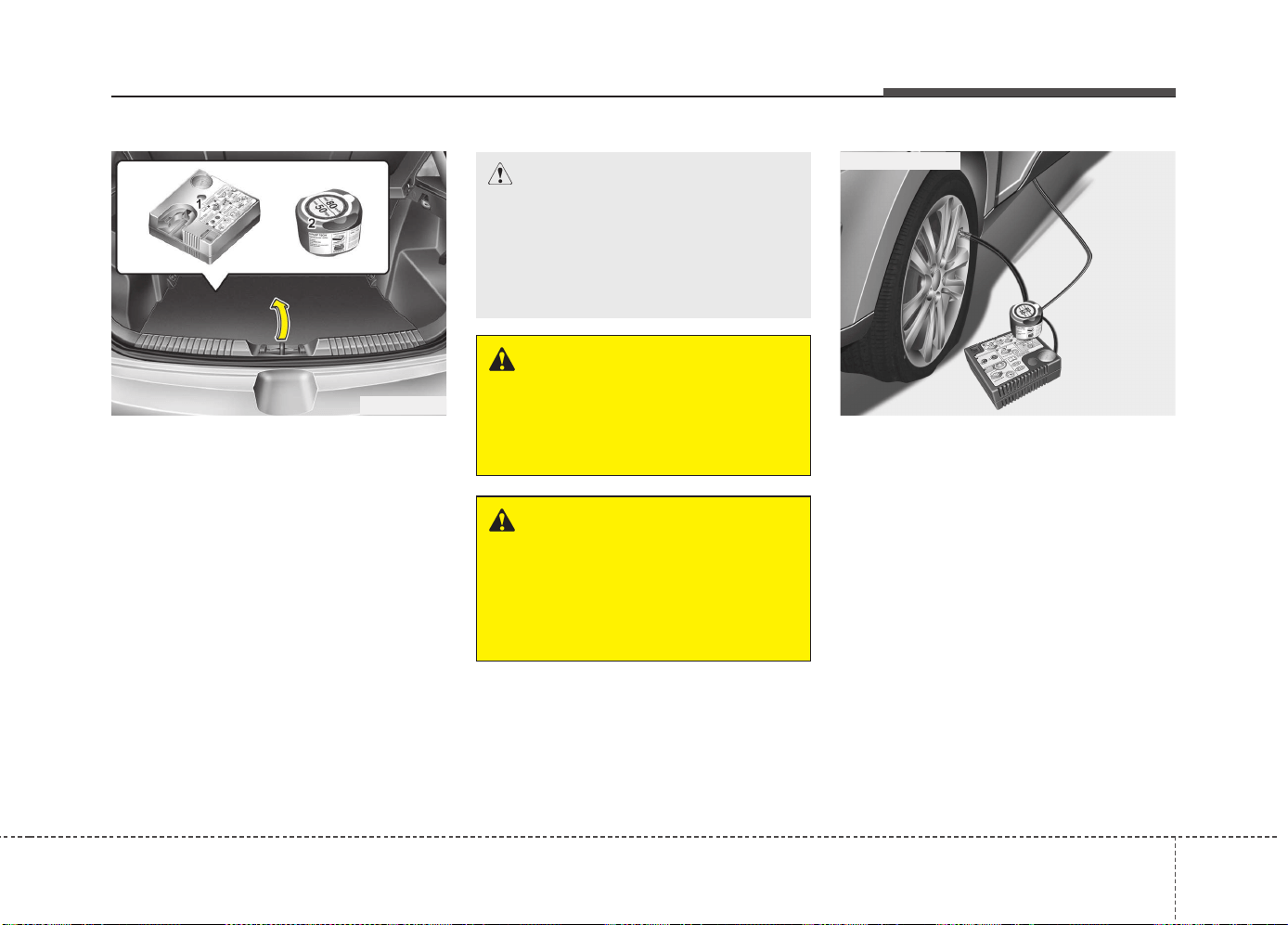
627
What to do in an emergency
For 17, 18 inch tire
For safe operation, carefully read
and follow the instructions in this
manual before use.
(1) Compressor
(2) Sealant bottle
The Tire Mobility Kit is a temporary
fix to the tire and we recommend that
the system be inspected by an
authorized Kia dealer.
Introduction
With the Tire Mobility Kit you stay
mobile even after experiencing a tire
puncture.
The system of compressor and seal-
ing compound effectively and com-
fortably seals most punctures in a
passenger car tire caused by nails
or similar objects and reinflates the
tire.
After you ensured that the tire is
properly sealed you can drive cau-
tiously on the tire (distance up to 200
km (120 miles)) at a max. speed of
80 km/h (50 mph) in order to reach a
service station or tire dealer to have
the tire replaced.
OJD064011
CAUTION
When two or more tires are flat,
do not use the tire mobility kit
because the supported one
sealant of Tire Mobility Kit is only
used for one flat tire.
WARNING
Do not use the Tire Mobility Kit
to repair punctures in the tire
walls. This can result in an acci-
dent due to tire failure.
WARNING
Have your tire repaired as soon
as possible. The tire may loose
air pressure at any time after
inflating with the Tire Mobility
Kit.
OEL069019
■ for 17 inch tire
What to do in an emergency
286
It is possible that some tires, espe-
cially with larger punctures or dam-
age to the sidewall, cannot be sealed
completely.
Air pressure loss in the tire may
adversely affect tire performance.
For this reason, you should avoid
abrupt steering or other driving
maneuvers, especially if the vehicle
is heavily loaded or if a trailer is in
use.
The Tire Mobility Kit is not designed
or intended as a permanent tire
repair method and is to be used for
one tire only. This instruction shows
you step by step how to temporarily
seal the puncture simply and reliably.
Read the section “Notes on the safe
use of the Tire Mobility Kit”.
Notes on the safe use of the Tire
Mobility Kit
• Park your car at the side of the
road so that you can work with the
Tire Mobility Kit away from moving
traffic.
• To be sure your vehicle will not
move, even when you're on fairly
level ground, always set your park-
ing brake.
• Only use the Tire Mobility Kit for
sealing/inflation passenger car
tires. Only punctured areas located
within the tread region of the tire
can be sealed using the tire mobil-
ity kit.
• Do not use on motorcycles, bicy-
cles or any other type of tires.
• When the tire and wheel are dam-
aged, do not use Tire Mobility Kit
for your safety.
• Use of the Tire Mobility Kit may not
be effective for tire damage larger
than approximately 6 mm (0.24 in).
If the tire cannot be made roadwor-
thy with the Tire Mobility Kit, we
recommend that you contact an
authorized Kia dealer.
WARNING
Do not use the TMK if a tire is
severely damaged by driving
run flat or with insufficient air
pressure.
Only punctured areas located
within the tread region of the
tire can be sealed using the
TMK.

629
What to do in an emergency
• Do not use the Tire Mobility Kit if a
tire is severely damaged by driving
run flat or with insufficient air pres-
sure.
• Do not remove any foreign objects
such as nails or screws that have
penetrated the tire.
• Provided the car is outdoors, leave
the engine running. Otherwise
operating the compressor may
eventually drain the car battery.
• Never leave the Tire Mobility Kit
unattended while it is being used.
• Do not leave the compressor run-
ning for more than 10 min. at a time
or it may overheat.
• Do not use the Tire Mobility Kit if
the ambient temperature is below -
30°C (-22°F).
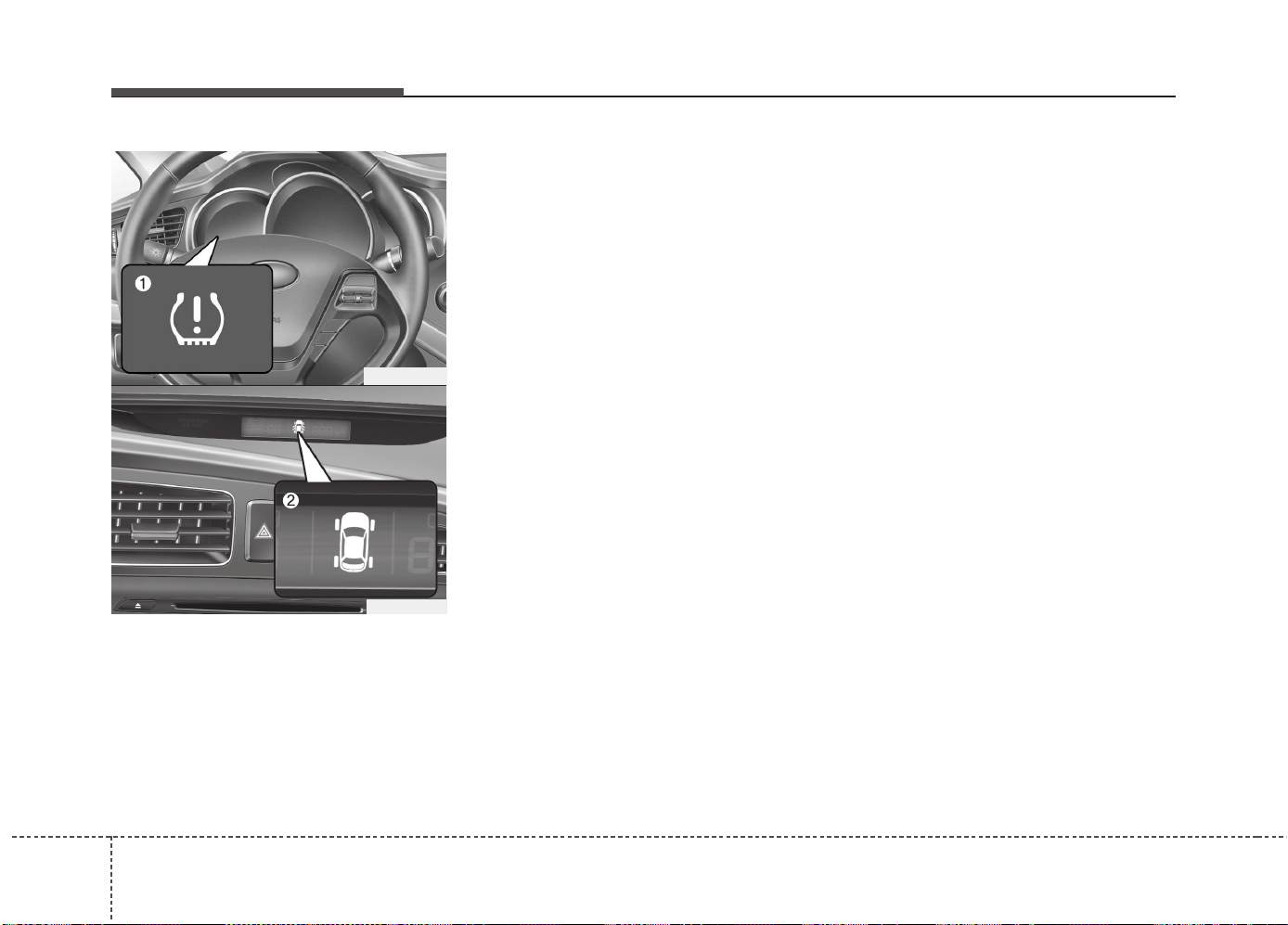
What to do in an emergency
306
TIRE PRESSURE MONITORING SYSTEM (TPMS)
(1) Low tire pressure telltale /
TPMS malfunction indicator
(2) Low tire pressure position telltale
(Shown on the instrument panel
display)
Each tire, including the spare (if pro-
vided), should be checked monthly
when cold and inflated to the inflation
pressure recommended by the vehicle
manufacturer on the vehicle placard or
tire inflation pressure label. (If your
vehicle has tires of a different size than
the size indicated on the vehicle plac-
ard or tire inflation pressure label, you
should determine the proper tire infla-
tion pressure for those tires.)
As an added safety feature, your vehi-
cle has been equipped with a tire pres-
sure monitoring system (TPMS) that
illuminates a low tire pressure telltale
when one or more of your tires is sig-
nificantly under-inflated. Accordingly,
when the low tire pressure telltale illu-
minates, you should stop and check
your tires as soon as possible, and
inflate them to the proper pressure.
Driving on a significantly under-inflat-
ed tire causes the tire to overheat and
can lead to tire failure. Under-inflation
also reduces fuel efficiency and tire
tread life, and may affect the vehicle’s
handling and stopping ability.
Please note that the TPMS is not a
substitute for proper tire maintenance,
and it is the driver’s responsibility to
maintain correct tire pressure, even if
under-inflation has not reached the
level to trigger illumination of the
TPMS low tire pressure telltale.
Your vehicle has also been equipped
with a TPMS malfunction indicator to
indicate when the system is not oper-
ating properly. The TPMS malfunction
indicator is combined with the low tire
pressure telltale. When the system
detects a malfunction, the telltale will
flash for approximately 1 minute and
then remain continuously illuminated.
This sequence will continue upon
subsequent vehicle start-ups as long
as the malfunction exists. When the
TPMS malfunction indicator remains
illuminated after blinking for approxi-
mately 1 minute, the system may not
be able to detect or signal low tire
pressure as intended.
OJD062006
OJD042144
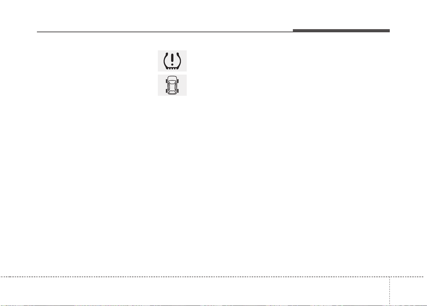
631
What to do in an emergency
TPMS malfunctions may occur for a
variety of reasons, including the
installation of replacement or alter-
nate tires or wheels on the vehicle
that prevent the TPMS from function-
ing properly. Always check the
TPMS malfunction telltale after
replacing one or more tires or wheels
on your vehicle to ensure that the
replacement or alternate tires and
wheels allow the TPMS to continue
to function properly.
✽✽
NOTICE
If any of the below happens, we rec-
ommend that the system be checked
by an authorized Kia dealer.
1.The low tire pressure telltale/
TPMS malfunction indicator do
not illuminate for 3 seconds when
the ignition switch is turned to the
ON position or engine is running.
2.The TPMS malfunction indicator
remains illuminated after blinking
for approximately 1 minute.
3.The Low tire pressure position
telltale remains illuminated.
Low tire pressure tell-
tale
Low tire pressure posi-
tion telltale
When the tire pressure monitoring
system warning indicators are illumi-
nated, one or more of your tires is
significantly under-inflated. The low
tire pressure position telltale light will
indicate which tire is significantly
under-inflated by illuminating the cor-
responding position light.
If either telltale illuminates, immedi-
ately reduce your speed, avoid hard
cornering and anticipate increased
stopping distances. You should stop
and check your tires as soon as pos-
sible. Inflate the tires to the proper
pressure as indicated on the vehicle’s
placard or tire inflation pressure label
located on the driver’s side center pil-
lar outer panel. If you cannot reach a
service station or if the tire cannot
hold the newly added air, replace the
low pressure tire with a spare tire.
If you drive the vehicle for about 10
minutes at speeds above 25 km/h
after replaceing the low pressure tire
with the spare tire, the below will
happen:
• The TPMS malfunction indicator
may blink for approximately 1
minute and then remain continuous-
ly illuminated because the TPMS
sensor is not mounted on the spare
wheel.
What to do in an emergency
326
Tire Pressure Monitoring
System (TPMS) malfunc-
tion indicator
The TPMS malfunction indicator will
illuminate after it blinks for approxi-
mately one minute when there is a
problem with the Tire Pressure
Monitoring System. If the system is
able to correctly detect an under infla-
tion warning at the same time as sys-
tem failure then the TPMS malfunc-
tion indicator remains illuminated after
blinking for approximately 1 minute.
We recommend that the system be
checked by an authorized Kia dealer to
determine the cause of the problem.
WARNING - Low pressure
damage
Significantly low tire pressure
makes the vehicle unstable and
can contribute to loss of vehicle
control and increased braking
distances.
Continued driving on low pres-
sure tires can cause the tires to
overheat and fail.
CAUTION
In winter or cold weather, the
low tire pressure telltale may
illuminate if the tire pressure
was adjusted to the recom-
mended tire inflation pressure
in warm weather. It does not
mean your TPMS is malfunction-
ing because the decreased tem-
perature leads to a proportional
lowering of tire pressure.
When you drive your vehicle
from a warm area to a cold area
or from a cold area to a warm
area, or the outside temperature
is greatly higher or lower, you
should check the tire inflation
pressure and adjust the tires to
the recommended tire inflation
pressure.

633
What to do in an emergency
Changing a tire with TPMS
If you have a flat tire, the low Tire
Pressure and Position telltales will
come on. We recommend that the
system be checked by an authorized
Kia dealer.
Each wheel is equipped with a tire
pressure sensor mounted inside the
tire behind the valve stem. You must
use TPMS specific wheels. It is rec-
ommended that you have your tires
serviced by an authorized Kia dealer.
If you drive the vehicle for about 10
minutes at speeds above 25 km/h
after replaceing the low pressure tire
with the spare tire, the below will
happen:
• The TPMS malfunction indicator
may blink for approximately 1
minute and then remain continuous-
ly illuminated because the TPMS
sensor is not mounted on the
sparewheel.
CAUTION
• The TPMS malfunction indica-
tor may blink for approximate-
ly 1 minute and then remain
continuously illuminated if the
vehicle is moving around elec-
tric power supply cables or
radios transmitter such as at
police stations, government
and public offices, broadcast-
ing stations, military installa-
tions, airports, or transmitting
towers, etc. This can interfere
with normal operation of the
Tire Pressure Monitoring
System (TPMS).
• The TPMS malfunction indica-
tor may blink for approximate-
ly 1 minute and then remain
continuously illuminated if
snow chains are used or some
separate electronic devices
such as notebook computer,
mobile charger, remote starter
or navigation etc., are used in
the vehicle. This can interfere
with normal operation of the
Tire Pressure Monitoring
System (TPMS).
CAUTION
We recommend that you use the
sealant approved by Kia.
The sealant on the tire pressure
sensor and wheel shall be elem-
inated when you replace the tire
with a new one.
What to do in an emergency
346
You may not be able to identify a low
tire by simply looking at it. Always
use a good quality tire pressure
gauge to measure the tire's inflation
pressure. Please note that a tire that
is hot (from being driven) will have a
higher pressure measurement than a
tire that is cold (from sitting station-
ary for at least 3 hours and driven
less than 1.6 km (1 mile) during that
3 hour period).
Allow the tire to cool before measur-
ing the inflation pressure. Always be
sure the tire is cold before inflating to
the recommended pressure.
A cold tire means the vehicle has
been sitting for 3 hours and driven for
less than 1.6 km (1 mile) in that 3
hour period.
WARNING - Protecting
TPMS
Tampering with, modifying, or
disabling the Tire Pressure
Monitoring System (TPMS) com-
ponents may interfere with the
system's ability to warn the driv-
er of low tire pressure condi-
tions and/or TPMS malfunctions.
Tampering with, modifying, or
disabling the Tire Pressure
Monitoring System (TPMS) com-
ponents may void the warranty
for that portion of the vehicle.
WARNING - TPMS
• The TPMS cannot alert you to
severe and sudden tire dam-
age caused by external factors
such as nails or road debris.
• If you feel any vehicle instabil-
ity, immediately take your foot
off the accelerator, apply the
brakes gradually and with
light force, and slowly move to
a safe position off the road.
CAUTION
We recommend that you use the
sealant approved by Kia if your
vehicle is equipped with a Tire
Pressure Monitoring System.
The liquid sealant can damage
the tire pressure sensors.

635
What to do in an emergency
WARNING - For EUROPE
• Do not modify the vehicle, it
may interfere with the TPMS
function.
• The wheels on the market do
not have a TPMS sensor.
For your safety, we recom-
mend that you use parts for
replacement from an author-
ized Kia dealer.
• If you use the wheels on the
market, use a TPMS sensor
approved by a Kia dealer. If
your vehicle is not equipped
with a TPMS sensor or TPMS
does not work properly, you
may fail the periodic vehicle
inspection conducted in your
country.
❈
❈
All vehicles sold in the
EUROPE market during
below period must be
equipped with TPMS.
- New model vehicle :
Nov. 1, 2012 ~
- Current model vehicle :
Nov. 1, 2014~ (Based on vehi-
cle registrations)
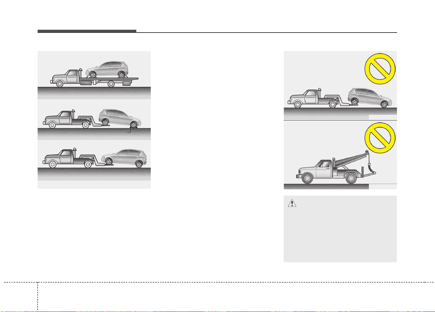
What to do in an emergency
366
TOWING
Towing service
If emergency towing is necessary, we
recommend having it done by an author-
ized Kia dealer or a commercial tow-truck
service. Proper lifting and towing proce-
dures are necessary to prevent damage
to the vehicle. The use of wheel dollies or
flatbed is recommended.
For trailer towing guidelines information,
refer to “Trailer towing” in chapter 5.
It is acceptable to tow the vehicle with the
rear wheels on the ground (without dol-
lies) and the front wheels off the ground.
If any of the loaded wheels or suspen-
sion components are damaged or the
vehicle is being towed with the front
wheels on the ground, use a towing dolly
under the front wheels.
When being towed by a commercial tow
truck and wheel dollies are not used, the
front of the vehicle should always be lift-
ed, not the rear.
✽✽
NOTICE
If the EPB does not release normally, we
recommend taking your vehicle to an
authorized Kia dealer by loading the
vehicle on a flatbed tow truck and have
the system checked.
CAUTION
• Do not tow the vehicle backwards
with the front wheels on the
ground as this may cause dam-
age to the vehicle.
• Do not tow with sling-type equip-
ment. Use wheel lift or flatbed
equipment.
OED066011
OED066012
dolly
OED066014
OED066013
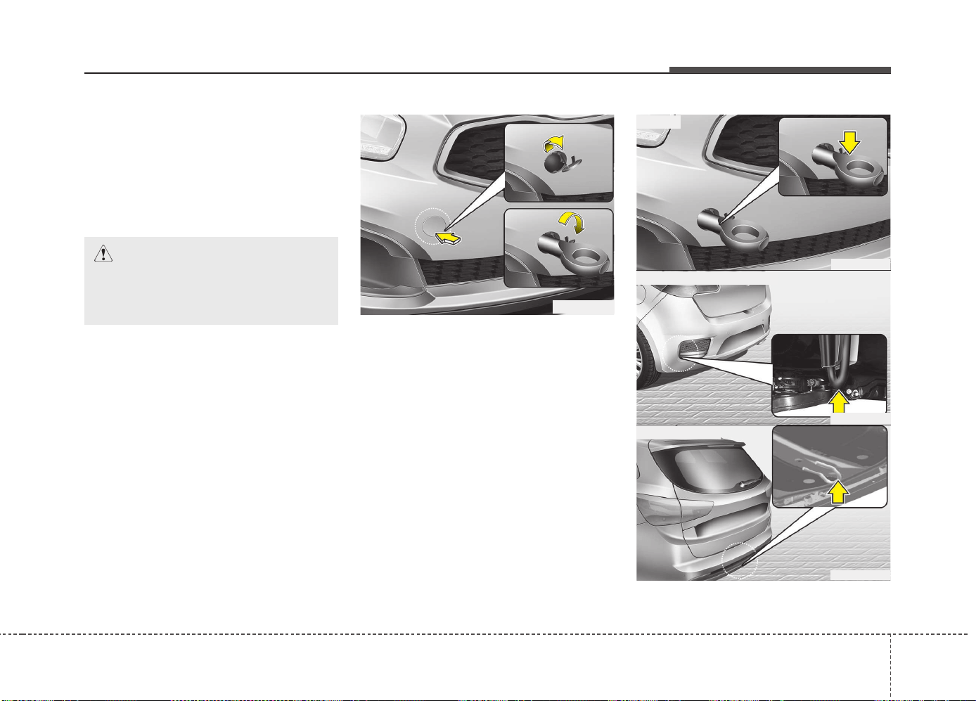
637
What to do in an emergency
When towing your vehicle in an emer-
gency without wheel dollies :
1. Set the ignition switch in the ACC posi-
tion.
2. Place the transaxle shift lever in N
(Neutral).
3. Release the parking brake.
Removable towing hook
(if equipped)
1. Open the tailgate/trunk, and remove
the towing hook from the tool case.
2. Remove the hole cover pressing the
lower part of the cover on the front
bumper.
3. Install the towing hook by turning it
clockwise into the hole until it is fully
secured.
4. Remove the towing hook and install
the cover after use.
Emergency towing
CAUTION
Failure to place the transaxle shift
lever in N (Neutral) may cause inter-
nal damage to the transaxle.
OJD065008
■ Rear (3 Door and 5 Door)
OJD062012
■ Rear (wagon)
■ Front
OJD065009
OJD065010
What to do in an emergency
386
If towing is necessary, we recommend
you to have it done by an authorized
Kia dealer or a commercial tow truck
service.
If towing service is not available in an
emergency, your vehicle may be tem-
porarily towed using a cable or chain
secured to the emergency towing hook
under the front (or rear) of the vehicle.
Use extreme caution when towing the
vehicle. A driver must be in the vehicle to
steer it and operate the brakes.
Towing in this manner may be done only
on hard-surfaced roads for a short dis-
tance and at low speed. Also, the wheels,
axles, power train, steering and brakes
must all be in good condition.
• Do not use the towing hooks to pull a
vehicle out of mud, sand or other con-
ditions from which the vehicle cannot
be driven out under its own power.
• Avoid towing a vehicle heavier than the
vehicle doing the towing.
• The drivers of both vehicles should com-
municate with each other frequently.
• Before emergency towing, check that
the hook is not broken or damaged.
• Fasten the towing cable or chain
securely to the hook.
• Do not jerk the hook. Apply steady and
even force.
• To avoid damaging the hook, do not
pull from the side or at a vertical angle.
Always pull straight ahead.
CAUTION
• Attach a towing strap to the tow
hook.
• Using a portion of the vehicle
other than the tow hooks for tow-
ing may damage the body of your
vehicle.
• Use only a cable or chain specifi-
cally intended for use in towing
vehicles. Securely fasten the
cable or chain to the towing hook
provided.
WARNING
Use extreme caution when towing
the vehicle.
• Avoid sudden starts or erratic
driving maneuvers which would
place excessive stress on the
emergency towing hook and tow-
ing cable or chain. The hook and
towing cable or chain may break
and cause serious injury or dam-
age.
• If the disabled vehicle is unable
to be moved, do not forcibly con-
tinue the towing. We recommend
that you contact an authorized
Kia dealer or a commercial tow
truck service for assistance.
• Tow the vehicle as straight ahead
as possible.
• Keep away from the vehicle dur-
ing towing.
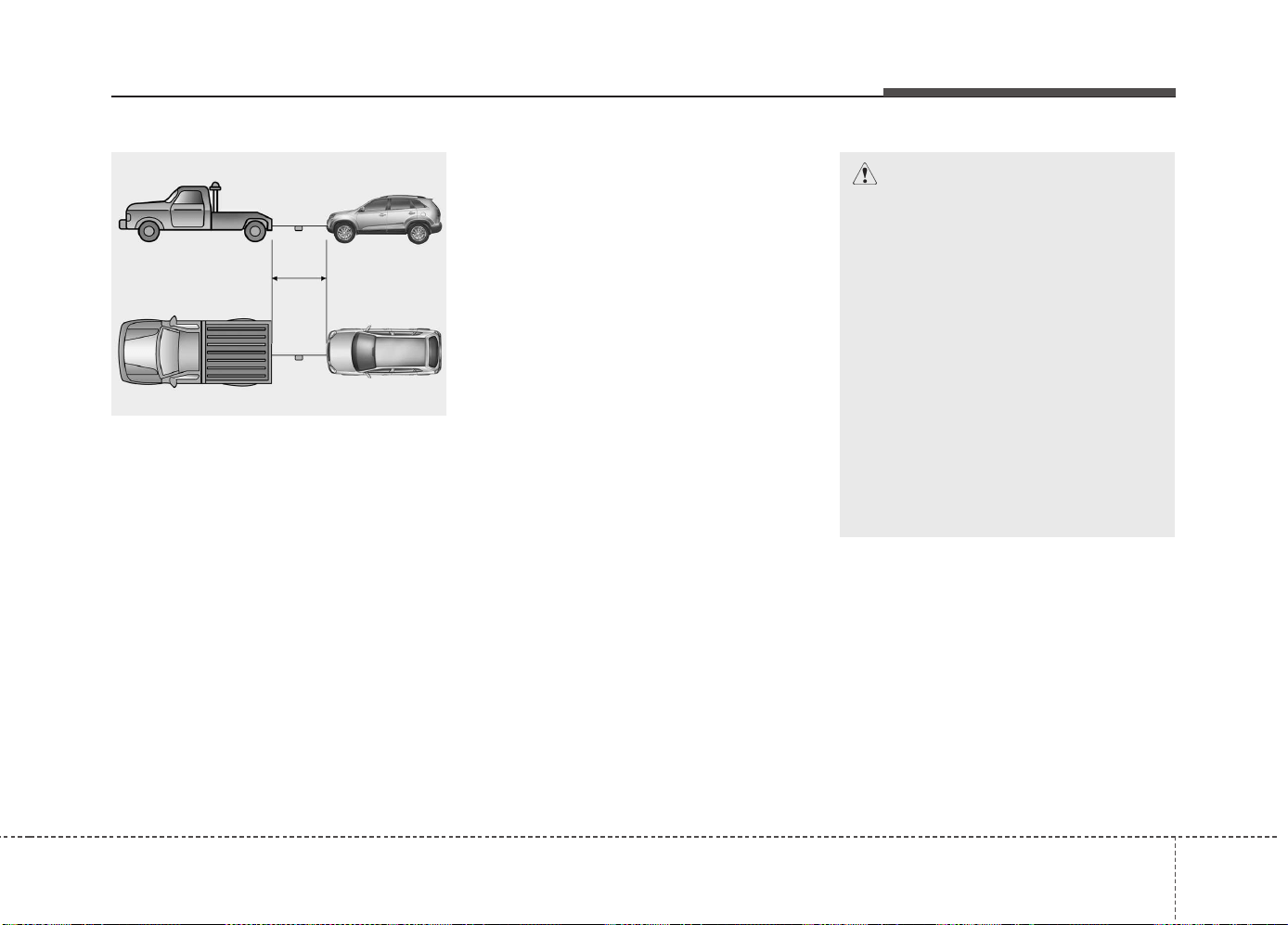
639
What to do in an emergency
• Use a towing strap less than 5 m (16
feet) long. Attach a white or red cloth
(about 30 cm (12 inches) wide) in the
middle of the strap for easy visibility.
• Drive carefully so that the towing strap
is not loosened during towing.
Emergency towing precautions
• Turn the ignition switch to ACC so the
steering wheel isn’t locked.
• Place the transaxle shift lever in N
(Neutral).
• Release the parking brake.
• Depress the brake pedal with more
force than normal since you will have
reduced brake performance.
• More steering effort will be required
because the power steering system
will be disabled.
• If you are driving down a long hill, the
brakes may overheat and brake per-
formance will be reduced. Stop often
and let the brakes cool off.
OXM069009
CAUTION - Automatic
transaxle / Double clutch
transmission
• If the car is being towed with all
four wheels on the ground, it can
be towed only from the front. Be
sure that the transaxle is in neu-
tral. Be sure the steering is
unlocked by placing the ignition
switch in the ACC position. A driv-
er must be in the towed vehicle to
operate the steering and brakes.
• To avoid serious damage to the
automatic transaxle, limit the
vehicle speed to 15 km/h (10 mph)
and drive less than 1.5 km (1
mile) when towing.

What to do in an emergency
406
EMERGENCY COMMODITY (IF EQUIPPED)
There are some emergency commodities
in the vehicle to help you respond to the
emergency situation.
Fire extinguisher
If there is small fire and you know how to
use the fire extinguisher, take the follow-
ing steps carefully.
1. Pull the pin at the top of the extin-
guisher that keeps the handle from
being accidentally pressed.
2. Aim the nozzle toward the base of the
fire.
3. Stand approximately 2.5 m (8 ft) away
from the fire and squeeze the handle
to discharge the extinguisher. If you
release the handle, the discharge will
stop.
4. Sweep the nozzle back and forth at the
base of the fire. After the fire appears
to be out, watch it carefully since it
may re-ignite.
First aid kit
There are some items such as scissors,
bandage and adhesive tape and etc. in
the kit to give first aid to an injured per-
son.
Triangle reflector
Place the triangle reflector on the road to
warn oncoming vehicles during emer-
gencies, such as when the vehicle is
parked by the roadside due to any prob-
lems.
Tire pressure gauge
(If equipped)
Tires normally lose some air in day-to-
day use, and you may have to add a few
pounds of air periodically and it is not
usually a sign of a leaking tire, but of nor-
mal wear. Always check tire pressure
when the tires are cold because tire pres-
sure increases with temperature.
To check the tire pressure, take the fol-
lowing steps:
1. Unscrew the inflation valve cap that is
located on the rim of the tire.
2. Press and hold the gauge against the
tire valve. Some air will escape as you
begin and more will escape if you don't
press the gauge in firmly.
3. A firm non-leaking push will activate
the gauge.
4. Read the tire pressure on the gauge to
know whether the tire pressure is low
or high.
5. Adjust the tire pressures to the speci-
fied pressure. Refer to “Tires and
wheels” in chapter 8.
6. Reinstall the inflation valve cap.
Maintenance
Engine compartment . . . . . . . . . . . . . . . . . . . . . . . . 7-3
Maintenance services. . . . . . . . . . . . . . . . . . . . . . . . 7-7
• Owner’s responsibility . . . . . . . . . . . . . . . . . . . . . . . . . 7-7
• Owner maintenance precautions . . . . . . . . . . . . . . . . 7-7
• Engine compartment precautions (Diesel engine). . . 7-8
Owner maintenance . . . . . . . . . . . . . . . . . . . . . . . . . 7-9
• Owner maintenance schedule . . . . . . . . . . . . . . . . . . . 7-9
Scheduled maintenance service . . . . . . . . . . . . . . . 7-11
• Normal maintenance schedule
- for Europe (Except Russia). . . . . . . . . . . . . . . . . . . 7-12
• Maintenance under severe usage conditions
- for Europe (Except Russia). . . . . . . . . . . . . . . . . . . 7-16
• Normal maintenance schedule
- except Europe (Including Russia) . . . . . . . . . . . . . 7-18
• Maintenance under severe usage conditions
- except Europe (Including Russia) . . . . . . . . . . . . . 7-22
Explanation of scheduled maintenance items . . . . 7-24
Engine oil . . . . . . . . . . . . . . . . . . . . . . . . . . . . . . . . . 7-27
• Checking the engine oil level. . . . . . . . . . . . . . . . . . . . 7-27
• Changing the engine oil and filter . . . . . . . . . . . . . . . 7-28
Engine coolant . . . . . . . . . . . . . . . . . . . . . . . . . . . . . 7-29
• Checking the coolant level. . . . . . . . . . . . . . . . . . . . . . 7-29
• Changing the coolant . . . . . . . . . . . . . . . . . . . . . . . . . . 7-31
Brake/clutch fluid . . . . . . . . . . . . . . . . . . . . . . . . . . 7-32
• Checking the brake fluid level . . . . . . . . . . . . . . . . . . 7-32
Washer fluid . . . . . . . . . . . . . . . . . . . . . . . . . . . . . . . 7-33
• Checking the washer fluid level . . . . . . . . . . . . . . . . . 7-33
Parking brake - hand type . . . . . . . . . . . . . . . . . . . 7-33
• Checking the parking brake . . . . . . . . . . . . . . . . . . . . 7-33
Fuel filter (for Diesel) . . . . . . . . . . . . . . . . . . . . . . . 7-34
• Draining water from fuel filter . . . . . . . . . . . . . . . . . . 7-34
Air cleaner . . . . . . . . . . . . . . . . . . . . . . . . . . . . . . . . 7-35
• Filter replacement . . . . . . . . . . . . . . . . . . . . . . . . . . . . 7-35
Climate control air filter . . . . . . . . . . . . . . . . . . . . . 7-37
• Filter inspection . . . . . . . . . . . . . . . . . . . . . . . . . . . . . . 7-37
• Filter replacement . . . . . . . . . . . . . . . . . . . . . . . . . . . . 7-37
Wiper blades. . . . . . . . . . . . . . . . . . . . . . . . . . . . . . . 7-39
• Blade inspection . . . . . . . . . . . . . . . . . . . . . . . . . . . . . . 7-39
• Blade replacement . . . . . . . . . . . . . . . . . . . . . . . . . . . . 7-39
Battery. . . . . . . . . . . . . . . . . . . . . . . . . . . . . . . . . . . . 7-42
• For best battery service . . . . . . . . . . . . . . . . . . . . . . . . 7-42
• Battery capacity label . . . . . . . . . . . . . . . . . . . . . . . . . 7-43
• Battery recharging . . . . . . . . . . . . . . . . . . . . . . . . . . . . 7-43
• Reset items . . . . . . . . . . . . . . . . . . . . . . . . . . . . . . . . . . 7-44
Tires and wheels. . . . . . . . . . . . . . . . . . . . . . . . . . . . 7-45
• Tire care. . . . . . . . . . . . . . . . . . . . . . . . . . . . . . . . . . . . . 7-45
• Recommended cold tire inflation pressures. . . . . . . . 7-45
• Checking tire inflation pressure . . . . . . . . . . . . . . . . . 7-47
• Tire rotation . . . . . . . . . . . . . . . . . . . . . . . . . . . . . . . . . 7-48
• Wheel alignment and tire balance . . . . . . . . . . . . . . . 7-49
7
JD PE eng 7.QXP 03.01.2017 17:16 Page 1
• Tire replacement. . . . . . . . . . . . . . . . . . . . . . . . . . . . . . 7-49
• Wheel replacement . . . . . . . . . . . . . . . . . . . . . . . . . . . . 7-51
• Tire traction . . . . . . . . . . . . . . . . . . . . . . . . . . . . . . . . . 7-51
• Tire maintenance . . . . . . . . . . . . . . . . . . . . . . . . . . . . . 7-51
• Tire sidewall labeling . . . . . . . . . . . . . . . . . . . . . . . . . . 7-51
• Low aspect ratio tire . . . . . . . . . . . . . . . . . . . . . . . . . . 7-55
Fuses . . . . . . . . . . . . . . . . . . . . . . . . . . . . . . . . . . . . . 7-56
• Fuse/relay panel description . . . . . . . . . . . . . . . . . . . . 7-61
Light bulbs . . . . . . . . . . . . . . . . . . . . . . . . . . . . . . . . 7-79
• Front light replacement . . . . . . . . . . . . . . . . . . . . . . . . 7-80
• Headlight and front fog light aiming (for Europe) . . 7-85
• Side repeater light bulb replacement . . . . . . . . . . . . . 7-93
• Rear combination light bulb replacement . . . . . . . . . 7-93
• High mounted stop light bulb replacement . . . . . . . . 7-98
• License plate light bulb replacement . . . . . . . . . . . . . 7-98
• Interior light bulb replacement. . . . . . . . . . . . . . . . . . 7-99
Appearance care. . . . . . . . . . . . . . . . . . . . . . . . . . . . 7-100
• Exterior care . . . . . . . . . . . . . . . . . . . . . . . . . . . . . . . . . 7-100
• Interior care . . . . . . . . . . . . . . . . . . . . . . . . . . . . . . . . . 7-105
Emission control system . . . . . . . . . . . . . . . . . . . . . 7-107
7
JD PE eng 7.QXP 03.01.2017 17:16 Page 2
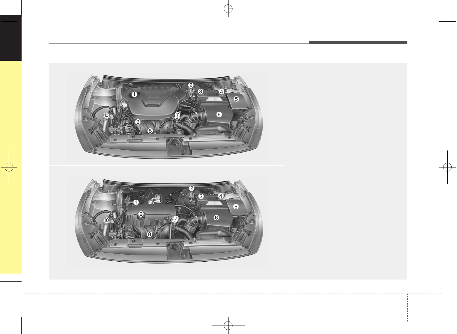
73
Maintenance
ENGINE COMPARTMENT
OJD072001/OJD072002
❈ The actual engine room in the vehicle may differ from the illustration.
1. Engine oil filler cap
2. Brake/clutch fluid reservoir
3. Positive battery terminal
4. Negative battery terminal
5. Fuse box
6. Air cleaner
7. Radiator cap
8. Engine coolant reservoir
9. Engine oil dipstick
10. Windshield washer fluid reservoir
■■
Gasoline engine (Gamma 1.6GDI)
■■
Gasoline engine (Gamma 1.6MPI)
JD PE eng 7.QXP 03.01.2017 17:16 Page 3
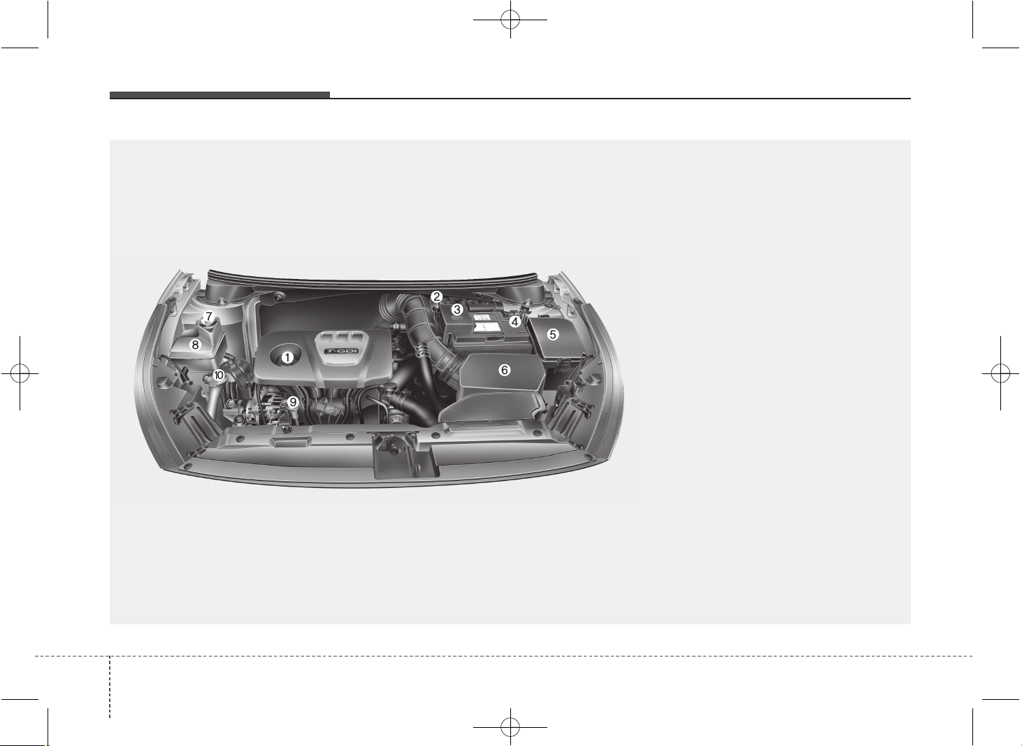
Maintenance
47
OJD075106L
❈ The actual engine room in the vehicle may differ from the illustration.
■
■
Gasoline engine (Gamma 1.6T-GDI)
1. Engine oil filler cap
2. Brake/clutch fluid reservoir
3. Positive battery terminal
4. Negative battery terminal
5. Fuse box
6. Air cleaner
7. Radiator cap
8. Engine coolant reservoir
9. Engine oil dipstick
10. Windshield washer fluid reservoir
JD PE eng 7.QXP 03.01.2017 17:16 Page 4
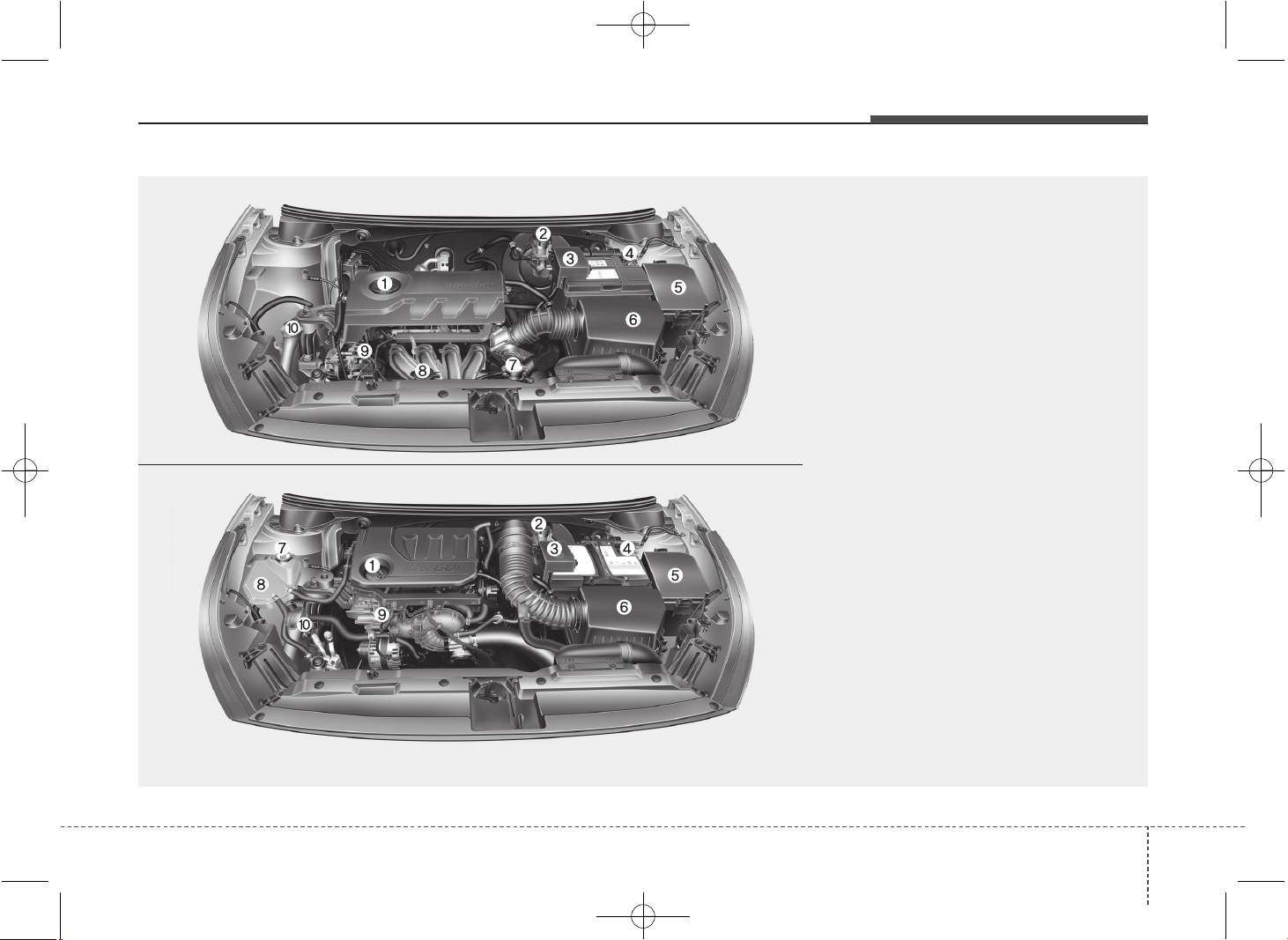
75
Maintenance
OJD075002/OJD075100L
❈ The actual engine room in the vehicle may differ from the illustration.
1. Engine oil filler cap
2. Brake/clutch fluid reservoir
3. Positive battery terminal
4. Negative battery terminal
5. Fuse box
6. Air cleaner
7. Radiator cap
8. Engine coolant reservoir
9. Engine oil dipstick
10. Windshield washer fluid reservoir
■■
Gasoline Engine (Kappa 1.4MPI)
■■
Gasoline Engine (Kappa 1.0 T-GDI)
JD PE eng 7.QXP 03.01.2017 17:16 Page 5
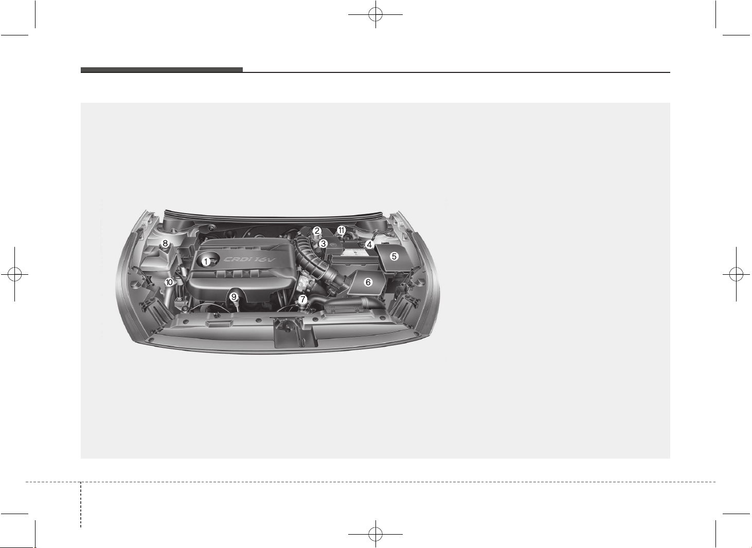
Maintenance
67
OJD075101L
❈ The actual engine room in the vehicle may differ from the illustration.
1. Engine oil filler cap
2. Brake/clutch fluid reservoir
3. Positive battery terminal
4. Negative battery terminal
5. Fuse box
6. Air cleaner
7. Radiator cap
8. Engine coolant reservoir
9. Engine oil dipstick
10. Windshield washer fluid reservoir
11. Fuel filter
■■
Diesel engine (UII)
JD PE eng 7.QXP 03.01.2017 17:16 Page 6
77
Maintenance
MAINTENANCE SERVICES
You should exercise the utmost care to
prevent damage to your vehicle and injury
to yourself whenever performing any
maintenance or inspection procedures.
Inadequate, incomplete or insufficient
servicing may result in operational prob-
lems with your vehicle that could lead to
vehicle damage, an accident, or person-
al injury.
Owner’s responsibility
✽✽
NOTICE
Maintenance Service and Record
Retention are the owner's responsibility.
We recommend in general that you have
your vehicle serviced by an authorized
Kia dealer. You should retain documents
that show proper maintenance has been
performed on your vehicle in accordance
with the maintenance schedule.You need
this information to establish your compli-
ance with the servicing and maintenance
requirements of your vehicle warranties.
Detailed warranty information is provided
in your Warranty & Maintenance book.
Repairs and adjustments required as a
result of improper maintenance or a lack
of required maintenance are not covered
when your vehicle is covered by warranty.
Owner maintenance precautions
Improper or incomplete service may
result in problems. This chapter gives
instructions only for the maintenance
items that are easy to perform.
✽✽
NOTICE
Improper owner maintenance during
the warranty period may affect warran-
ty coverage. For details, read the sepa-
rate Warranty & Maintenance book
provided with the vehicle. If you're
unsure about any servicing or mainte-
nance procedure, we recommend that
the system be checked by an authorized
Kia dealer.
CAUTION
• Do not put heavy objects or apply
excessive force on top of the
engine cover (if equipped) or fuel
related parts.
• When you inspect the fuel system
(fuel lines and fuel injection
devices), we recommend that you
contact an authorized kia dealer.
• Do not drive long time with the
engine cover (if equipped)
removed.
• When checking the engine room,
do not go near fire.
Fuel, washer fluid, etc. are flam-
mable oils that may cause fire.
• Before touching the battery, igni-
tion cables and electrical wiring,
you should disconnect the battery
"-" terminal. You may get an elec-
tric shock from the electric current.
• When you remove the interior trim
cover with a flat bed (-) driver, be
careful not to damage the cover.
• Be careful when you replace and
clean bulbs to avoid burns or
electrical shock.
JD PE eng 7.QXP 03.01.2017 17:16 Page 7
Maintenance
87
Engine compartment precautions
(Diesel engine)
• The injector operates at high voltage
(maximum 200v). Therefore, the follow-
ing accidents may occur.
- Direct contact with the injector or
injector wiring may cause electric
shock or damage your muscle or
nerve system.
- The electromagnetic wave from the
operating injector may cause the arti-
ficial heart pacemaker to malfunction.
• Follow the safety tips provided below,
when you are checking the engine
room while the engine is running.
- Do not touch the injector, injector
wirings, and the engine computer
while the engine is running.
- Do not remove the injector connector
while the engine is running.
- People using pacemakers must not
go near the engine while the engine
is starting or running.
WARNING - Maintenance
work
• Performing maintenance work on
a vehicle can be dangerous. You
can be seriously injured while
performing some maintenance
procedures. If you lack sufficient
knowledge and experience or the
proper tools and equipment to do
the work, we recommend that the
system be serviced by an author-
ized Kia dealer.
• Working under the hood with the
engine running is dangerous. It
becomes even more dangerous
when you wear jewelry or loose
clothing. These can become
entangled in moving parts and
result in injury. Therefore, if you
must run the engine while work-
ing under the hood, make certain
that you remove all jewelry (espe-
cially rings, bracelets, watches,
and necklaces) and all neckties,
scarves, and similar loose cloth-
ing before getting near the
engine or cooling fans.
WARNING - Diesel Engine
Never work on injection system
with engine running or within 30
seconds after shutting off engine.
High-pressure pump, rail, injectors
and high-pressure pipes are sub-
ject to high pressure even after the
engine stopped. The fuel jet pro-
duced by fuel leaks may cause seri-
ous injury, if it touches the body.
People using pacemakers should
not move than 30cm closer to the
ECU or wiring harness within the
engine room while engine is run-
ning, since the high currents in the
electronic engine control system
produce considerable magnetic
fields.
JD PE eng 7.QXP 03.01.2017 17:16 Page 8
79
Maintenance
OWNER MAINTENANCE
We recommend that the following lists
are vehicle checks and inspections that
should be performed by the owner or an
authorized Kia dealer at the frequencies
indicated to help ensure safe, depend-
able operation of your vehicle.
If you have any question, we recommend
that you consult an authorized Kia deal-
er.
These Owner Maintenance Checks are
generally not covered by warranties and
you may be charged for labor, parts and
lubricants used.
Owner maintenance schedule
When you stop for fuel:
• Check the engine oil level.
• Check coolant level in coolant reser-
voir.
• Check the windshield washer fluid
level.
• Look for low or under-inflated tires.
• Check the radiator and condenser.
Check if the front of the radiator and
condenser are clean and not blocked
with leaves, dirt or insects etc.
If any of the above parts are extremely
dirty or you are not sure of their condi-
tion, we recommend that you contact
an authorized Kia dealer.
While operating your vehicle:
• Note any changes in the sound of the
exhaust or any smell of exhaust fumes
in the vehicle.
• Check for vibrations in the steering
wheel. Notice any increased steering
effort or looseness in the steering
wheel, or change in its straight-ahead
position.
• Notice if your vehicle constantly turns
slightly or “pulls” to one side when trav-
eling on smooth, level road.
• When stopping, listen and check for
unusual sounds, pulling to one side,
increased brake pedal travel or “hard-
to-push” brake pedal.
• If any slipping or changes in the oper-
ation of your transaxle occurs, check
the transaxle fluid level.
• Check manual transaxle operation,
including clutch operation.
• Check automatic transaxle/dual clutch
transmission P (Park) function.
• Check parking brake.
• Check for fluid leaks under your vehicle
(water dripping from the air conditioning
system during or after use is normal).
WARNING
Be careful when checking your
engine coolant level when the
engine is hot. Scalding hot coolant
and steam may blow out under
pressure. This could cause burns
or other serious injury.
JD PE eng 7.QXP 03.01.2017 17:16 Page 9
Maintenance
107
At least monthly:
• Check coolant level in the engine
coolant reservoir.
• Check the operation of all exterior
lights, including the stoplights, turn sig-
nals and hazard warning flashers.
• Check the inflation pressures of all
tires including the spare.
At least twice a year
(i.e., every Spring and Fall) :
• Check radiator, heater and air condi-
tioning hoses for leaks or damage.
• Check windshield washer spray and
wiper operation. Clean wiper blades
with clean cloth dampened with wash-
er fluid.
• Check headlight alignment.
• Check muffler, exhaust pipes, shields
and clamps.
• Check the lap/shoulder belts for wear
and function.
• Check for worn tires and loose wheel
lug nuts.
At least once a year :
• Clean body and door drain holes.
• Lubricate door hinges and checks, and
hood hinges.
• Lubricate door and hood locks and
latches.
• Lubricate door rubber weatherstrips.
• Check the air conditioning system.
• Inspect and lubricate automatic
transaxle linkage and controls.
• Clean battery and terminals.
• Check the brake (and clutch) fluid
level.
JD PE eng 7.QXP 03.01.2017 17:16 Page 10

711
Maintenance
SCHEDULED MAINTENANCE SERVICE
Follow Normal Maintenance Schedule
if the vehicle is usually operated where
none of the following conditions apply. If
any of the following conditions apply, fol-
low Maintenance Under Severe Usage
Conditions.
• Repeated driving short distance of less
than 8 km (5 miles) in normal tempera-
ture or less than 16 km(10 miles) in
freezing temperature
• Extensive engine idling or low speed
driving for long distances
• Driving on rough, dusty, muddy,
unpaved, graveled or salt-spread
roads
• Driving in areas using salt or other cor-
rosive materials or in very cold weath-
er
• Driving in heavy dust condition
• Driving in heavy traffic area
• Driving on uphill, downhill, or mountain
road repeatedly
• Towing a trailer or using a camper, or
roof rack
• Driving as a patrol car, taxi, other com-
mercial use of vehicle towing
• Driving over 170 km/h (106 mile/h)
• Frequently driving in stop-and-go con-
dition
If your vehicle is operated under the
above conditions, you should inspect,
replace or refill more frequently than the
following Normal Maintenance Schedule.
After the periods or distance shown in
the chart, continue to follow the pre-
scribed maintenance intervals.
JD PE eng 7.QXP 03.01.2017 17:16 Page 11

Maintenance
127
NORMAL MAINTENANCE SCHEDULE - FOR EUROPE (EXCEPT RUSSIA)
The following maintenance services must be performed to ensure good emission control and performance. Keep receipts for all
vehicle emission services to protect your warranty. Where both mileage and time are shown, the frequency of service is deter-
mined by whichever occurs first.
*
1
: Check the engine oil level and leak every 500 km (350
miles) or before starting a long trip.
*
2
: This maintenance schedule depends on fuel quality. It is
applicable only when using a qualified fuel <"EN590 or
equivalent">. If the diesel fuel specifications don't meet the
EN590, it must be replaced according to the severe mainte-
nance schedule.
*
3
: If the recommended oil is not available, replace engine oil
and engine oil filter every 20,000 km or 12 months.
*
4
: If the recommended oil is not available, replace engine oil
and filter every 15,000 km for MPI engine and replace
engine oil and filter every 10,000 km for GDI engine.
*
5
: The engine oil level should be checked regularly and main-
tained properly. Operating with an insufficient amount of oil
can damage the engine, and such damage is not covered
by warranty.
*
6
: This maintenance schedule depends on fuel quality. It is
applicable only when using a qualified fuel <"EN590 or
equivalent">. If the diesel fuel specifications don't meet the
EN590, it must be replaced more frequently. If there are
some important safety matters like fuel flow restriction,
surging, loss of power, hard starting problem etc., replace
the fuel filter immediately regardless of maintenance sched-
ule and we recommended that you consult an authorized
Kia dealer for details.
*
7
: The fuel filter is considered to be maintenance free but peri-
odic inspection is recommended for this maintenance
schedule depends on fuel quality. If there are some impor-
tant matters like fuel flow restriction, surging, loss of power,
hard starting problem etc, replace the fuel filter immediately
regardless of maintenance schedule and we recommended
that you consult an authorized Kia dealer for details.
*
8
: Manual transaxle and dual clutch transmission fluid should
be changed anytime they have been submerged in water.
*
9
: Inspect drive belt tensioner, idler and alternator pulley and if
necessary correct or replace.
*
10
: When adding coolant, use only deionized water or soft
water for your vehicle and never mix hard water in the
coolant filled at the factory. An improper coolant mixture
can result in serious malfunction or engine damage.
*
11
: Inspect for excessive valve noise and/or engine vibration
and adjust if necessary. We recommended that the system
should be checked by an authorized Kia dealer.
*
12
: If good quality gasolines that meet Europe Fuel standards
(EN228) or equivalents including fuel additives is not avail-
able, one bottle of additive is recommended. Additives are
available from your authorized Kia dealer along with infor-
mation on how to use them. Do not mix other additives.
JD PE eng 7.QXP 03.01.2017 17:16 Page 12
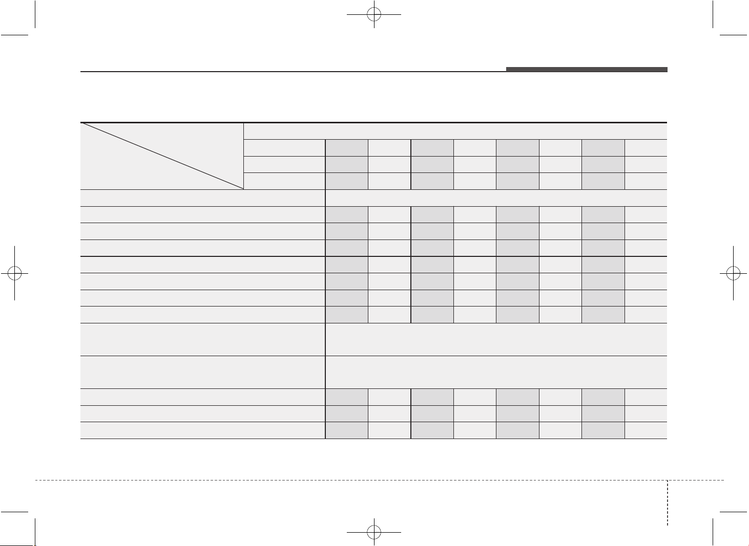
713
Maintenance
NORMAL MAINTENANCE SCHEDULE - FOR EUROPE (EXCEPT RUSSIA) (CONT.)
MAINTENANCE
INTERVALS
MAINTENANCE
ITEM
Number of months or driving distance, whichever comes first
Months
24 48 72 96 120 144 168 192
Kmx1,000
30 60 90 120 150 180 210 240
Milesx1,000
20 40 60 80 100 120 140 160
Add fuel additives (Gasoline) *
12
Every 15,000 km(10,000miles) or 12months
Air cleaner filter I R IRIRIR
Air conditioner refrigerant/compressor (if equipped) I I IIIIII
Battery condition IIIIIIII
Brake lines, hoses and connections
IIIIIIII
Brake / Clutch pedal (if equipped) IIIIIIII
Brake / Clutch fluid (if equipped) RRRRRRRR
Climate control air filter R R R R R R R R
Cooling system
At first, inspect 60,000 km (40,000 miles) or 48months
after that, every 30,000 km (20,000 miles) or 24months
Coolant *
8
At first, replace 210,000 km (140,000 miles) or 120 months
after that, every 30,000 km (20,000 miles) or 24 months *
5
Disc brakes and pads I I I I I I I I
Double clutch transmission fluid *
8
I I I I
Drive shafts and boots I I I I I I I I
JD PE eng 7.QXP 03.01.2017 17:17 Page 13
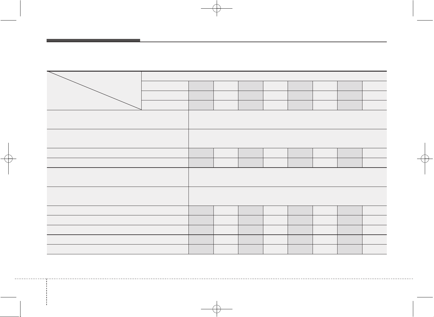
Maintenance
147
NORMAL MAINTENANCE SCHEDULE - FOR EUROPE (EXCEPT RUSSIA) (CONT.)
MAINTENANCE
INTERVALS
MAINTENANCE
ITEM
Number of months or driving distance, whichever comes first
Months
24 48 72 96 120 144 168 192
Kmx1,000
30 60 90 120 150 180 210 240
Milesx1,000
20 40 60 80 100 120 140 160
Drive belt (Diesel) *
9
At first, inspect 90,000 km (60,000 miles) or 48months
after that, every 30,000 km (20,000 miles) or 24months
Drive belt (Gasoline) *
9
At first, inspect 90,000 km (60,000 miles) or 72months
after that, every 30,000 km (20,000 miles) or 24months
Exhaust system I I IIIIII
Engine oil and filter (Diesel - UII) *
1
*
2
*
3
*
5
R R R R R R R R
Engine oil and filter
(Gamma GDI,MPI/Kappa MPI)*
1
*
4
*
5
Replace every 30,000km(20,000miles) or 24 months
Engine oil and filter
(Gasoline- Gamma /Kappa T-GDI)
*
1
*
5
Replace every 15,000km(10,000miles) or 12 months
All Electrical system IIIIIIII
Front suspension ball joints IIIIIIII
Fuel filter cartridge (Diesel) *
6
I R I R I R I R
Fuel filter (Gasoline) *
7
I I I I
Fuel tank air filter (Gasoline, if equipped) I I I I
JD PE eng 7.QXP 03.01.2017 17:17 Page 14
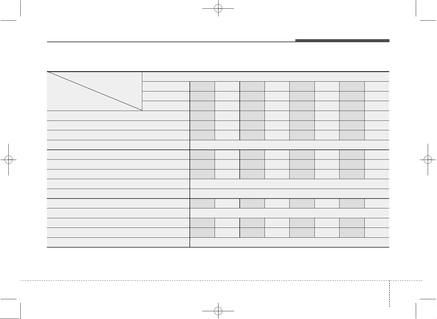
715
Maintenance
NORMAL MAINTENANCE SCHEDULE - FOR EUROPE (EXCEPT RUSSIA) (CONT.)
MAINTENANCE
INTERVALS
MAINTENANCE
ITEM
Number of months or driving distance, whichever comes first
Months
24 48 72 96 120 144 168 192
Kmx1,000
30 60 90 120 150 180 210 240
Milesx1,000
20 40 60 80 100 120 140 160
Fuel lines, fuel hoses and connections (Diesel) I I IIIIII
Fuel lines, fuel hoses and connections (Gasoline) I I I I
Fuel filler cap (Diesel) I I I I
Intercooler, in/out hose, air intake hose (Gasoline T-GDI) Inspect every 15,000 km (10,000 miles)
Manual transaxle fluid (if equipped) *
8
I I I I
Parking brake (Hand type) IIIIIIII
Spark plugs (Gamma MPI, Nickel) R R R R
Spark plugs (Gamma/Kappa T-GDI ,Iridium) Replace every 75,000 km (50,000 miles) or 60 months
Spark plugs (Gamma GDI, Kappa MPI, Iridium) Replace every 150,000 km (100,000 miles) or 120 months
Steering gear rack, linkage and boots I I I I I I I I
Tire (pressure & tread wear) Inspect every 30,000km(20,000miles) or 12 months
Valve clearance (Gasoline) *
11
I I
Vapor hose and fuel filler cap (Gasoline) I I I I
Automatic transaxle fluid No check, No service required
JD PE eng 7.QXP 03.01.2017 17:17 Page 15
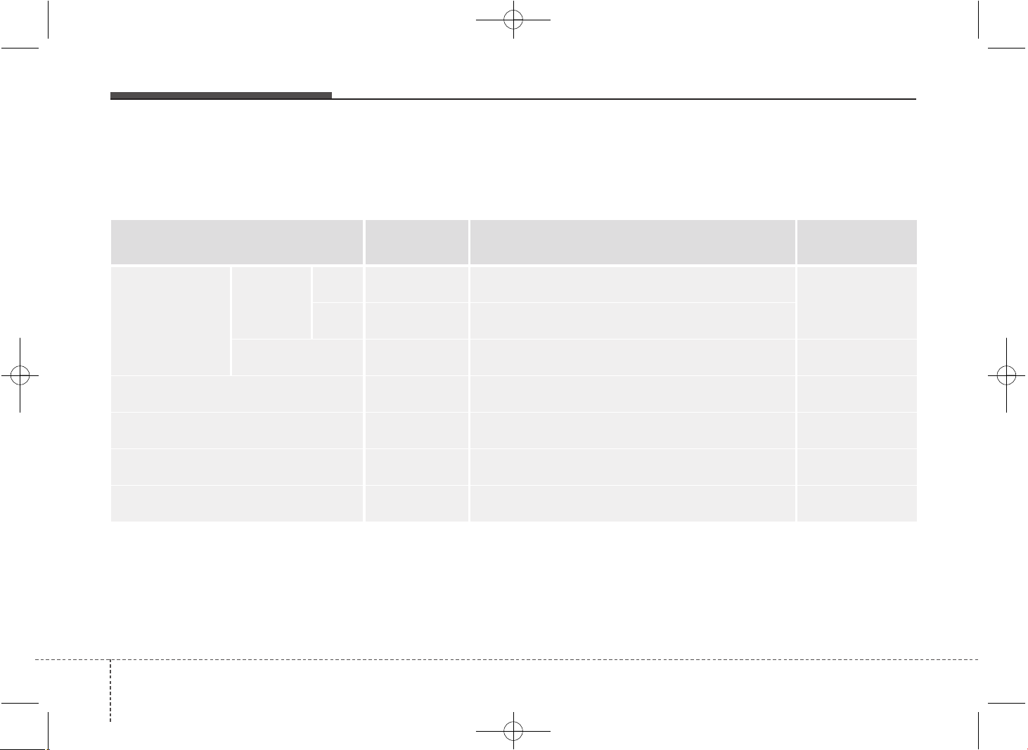
Maintenance
167
MAINTENANCE UNDER SEVERE USAGE CONDITIONS - FOR EUROPE (EXCEPT RUSSIA)
The following items must be serviced more frequently on cars mainly used under severe driving conditions.
Refer to the chart below for the appropriate maintenance intervals.
R : Replace I : Inspect and if necessary, adjust, correct, clean or replace
MAINTENANCE ITEM
MAINTENANCE
OPERATION
MAINTENANCE INTERVALS
DRIVING
CONDITION
Engine oil and
engine oil filter
Gasoline
MPI,
GDI*
1
R Every 15,000 km (10,000 miles) or 12 months
A, B, C, D, E, F,
G, H, I, J, K, L
T-GDI R Every 7,500km (5,000miles) or 6 months
Diesel *
2
R Every 15,000 km (10,000 miles) or 12 months
A, B, C, F, G,
H, I, J, K, L
Air cleaner filter R Replace more frequently depending on the condition C, E
Manual transaxle fluid (if equipped) R Every 120,000 km (80,000 miles)
C, D, E, F, G,
H, I, K
Dual clutch transmission fluid
(if equipped)
R Every 120,000 km (80,000 miles)
C, D, E, F, G,
H, I, K
Automatic transaxle fluid (if equipped) R Every 90,000 km (60,000 miles)
A, C, D, E, F,
G, H, I, K
*
1
: If the recommended oil is not available, replace engine oil and engine oil filter every 7,500 km or 6 months for MPI engine and
5,000 km or 6 months for GDI engine.
*
2
: If the recommended oil is not available, replace engine oil and engine oil filter every 10,000 km or 6 months.
JD PE eng 7.QXP 03.01.2017 17:17 Page 16
717
Maintenance
SEVERE DRIVING CONDITIONS
A : Repeated short distance driving
B : Extensive idling
C : Driving on rough, dusty, muddy, unpaved, graveled or
salt spread roads
D : Driving in areas using salt or other corrosive materials or
in very cold weather
E : Driving in sandy areas
F : More than 50 % driving in heavy city traffic during hot
weather above 32 °C (90 °F)
G : Driving in mountainous areas.
H : Towing a trailer or using a camper on roof rack
I : Driving for patrol car, taxi, commercial car or vehicle tow-
ing
J : Driving in very cold weather
K : Driving over 170 km/h (106 mile/h)
L : Frequently driving in stop-and-go conditions
MAINTENANCE ITEM
MAINTENANCE
OPERATION
MAINTENANCE INTERVALS
DRIVING
CONDITION
Steering gear rack, linkage and boots I Inspect more frequently depending on the condition C, D, E, F, G
Front suspension ball joints I Inspect more frequently depending on the condition C, D, E, F, G
Disc brakes and pads,
calipers and rotors
I Inspect more frequently depending on the condition C, D, E, G, H
Parking brake (Hand type) I Inspect more frequently depending on the condition C, D, G, H
Drive shaft and boots I Inspect more frequently depending on the condition
C, D, E, F,
G, H, I, J, K
Climate control air filter R Replace more frequently depending on the condition C, E, G
JD PE eng 7.QXP 03.01.2017 17:17 Page 17

Maintenance
187
NORMAL MAINTENANCE SCHEDULE - EXCEPT EUROPE (INCLUDING RUSSIA)
The following maintenance services must be performed to ensure good emission control and performance. Keep receipts for all
vehicle emission services to protect your warranty. Where both mileage and time are shown, the frequency of service is deter-
mined by whichever occurs first.
*
1
: Inspect drive belt tensioner, idler and alternator pulley and
if necessary correct or replace.
*
2
: Check the engine oil level and leak every 500 km (350
miles) or before starting a long trip.
*
3
: The engine oil level should be checked regularly and main-
tained properly. Operating with an insufficient amount of oil
can damage the engine, and such damage is not covered
by warranty.
*
4
: This maintenance schedule depends on fuel quality. It is
applicable only when using a qualified fuel <"EN590 or
equivalent">. If the diesel fuel specifications don't meet the
EN590, it must be replaced more frequently.
If there are some important safety matters like fuel flow
restriction, surging, loss of power, hard starting problem
etc., replace the fuel filter immediately regardless of main-
tenance schedule and we recommend that you consult an
authorized Kia dealer for details
*
5
: For your convenience, it can be replaced prior to it's interval
when you do maintenance of other items.
*
6
: Inspect for excessive valve noise and/or engine vibration
and adjust if necessary. We recommended that the system
should be checked by an authorized Kia dealer.
*
7
: The fuel filter is considered to be maintenance free but peri-
odic inspection is recommended for this maintenance
schedule depends on fuel quality. If there are some impor-
tant matters like fuel flow restriction, surging, loss of power,
hard starting problem etc, replace the fuel filter immediate-
ly regardless of maintenance schedule and we recommend
that you consult an authorized Kia dealer for details.
*
8
: When adding coolant, use only deionized water or soft
water for your vehicle and never mix hard water in the
coolant filled at the factory. An improper coolant mixture can
result in serious malfunction or engine damage.
*
9
: If good quality gasolines that meet Europe Fuel standards
(EN228) or equivalents including fuel additives is not avail-
able, one bottle of additive is recommended. Additives are
available from your authorized Kia dealer along with infor-
mation on how to use them. Do not mix other additives.
*
10
: If 5W-20 is used for GDI engine, replace engine oil and fil-
ter every 10,000 km.
JD PE eng 7.QXP 03.01.2017 17:17 Page 18
719
Maintenance
NORMAL MAINTENANCE SCHEDULE - EXCEPT EUROPE (INCLUDING RUSSIA) (CONT.)
MAINTENANCE
INTERVALS
MAINTENANCE
ITEM
Number of months or driving distance, whichever comes first
Months
12 24 36 48 60 72 84 96
Kmx1,000
15 30 45 60 75 90 105 120
Milesx1,000
10 20 30 40 50 60 70 80
Add fuel additives (Gasoline) *
9
Every 10,000 km (6,500miles) or 6months
Air cleaner filter (Except Middle East) I I RI IRII
Air cleaner filter (For Middle East) R R R R R R R R
Air conditioner refrigerant/compressor (if equipped)
I I I I I I I I
Battery condition IIIIIIII
Brake lines, hoses and connections IIIIIIII
Brake / Clutch pedal (if equipped) I I I I
Brake / Clutch fluid (if equipped) IIIIIIII
Climate control air filter R R R R R R R R
Cooling system
At first, inspect 60,000 km (40,000 miles) or 48 months
after that, every 30,000 km (20,000 miles) or 24 months
Coolant *
8
At first, replace 210,000 km (140,000 miles) or 120 months
after that, every 30,000 km (20,000 miles) or 24 months *
5
Disc brakes and pads I I I I I I I I
Drive shafts and boots I I I I
JD PE eng 7.QXP 03.01.2017 17:17 Page 19
Maintenance
207
NORMAL MAINTENANCE SCHEDULE - EXCEPT EUROPE (INCLUDING RUSSIA) (CONT.)
MAINTENANCE
INTERVALS
MAINTENANCE
ITEM
Number of months or driving distance, whichever comes first
Months
12 24 36 48 60 72 84 96
Kmx1,000
15 30 45 60 75 90 105 120
Milesx1,000
10 20 30 40 50 60 70 80
Drive belt (Diesel-For Russia) *
1
At first, inspect 90,000 km (60,000 miles) or 48months
after that, inspect every 30,000 km (20,000 miles) or 24monthsI
Drive belt (Diesel-Except Russia) *
1
At first, inspect 80,000 km (50,000 miles) or 48months
after that, inspect every 20,000 km (12,500 miles) or 12months
Drive belt (Gasoline) *
1
I I I I
Exhaust system
I I I I
Engine oil and filter (Diesel - UII)-For Russia *
2
*
3
RRRRRRRR
Engine oil and filter (Diesel - UII)-Except Russia *
2
*
3
Replace every 10,000 km (6,500 miles) or 12months
Engine oil and filter (Gasoline - Gamma MPI/GDI) *
2
*
10
RRRRRRRR
Engine oil and filter
(Gasoline - Gamma MPI ,For Middle east) *
2
Replace every 15,000 km (6,500 miles) or 12months
Engine oil and filter (Gasoline - Gamma T-GDI) *
2
*
3
Replace every 10,000 km (6,500 miles) or 6 months
All Electrical system I I I I
Front suspension ball joints I I I I I I I I
Fuel filter cartridge (Diesel) *
4
I R I R
Fuel filter (Gasoline) *
7
I R I R
JD PE eng 7.QXP 03.01.2017 17:17 Page 20
721
Maintenance
NORMAL MAINTENANCE SCHEDULE - EXCEPT EUROPE (INCLUDING RUSSIA) (CONT.)
MAINTENANCE
INTERVALS
MAINTENANCE
ITEM
Number of months or driving distance, whichever comes first
Months
12 24 36 48 60 72 84 96
Kmx1,000
15 30 45 60 75 90 105 120
Milesx1,000
10 20 30 40 50 60 70 80
Fuel filler cap (Diesel)
I I
Fuel tank air filter (Gasoline, if equipped)
I R I R
Fuel lines, fuel hoses and connections (Diesel)
I I I I
Fuel lines, fuel hoses and connections (Gasoline)
I I
Intercooler, in/out hose, air intake hose
(Gasoline T-GDI)
I I I I I I I I
Manual transaxle fluid (if equipped)
I I
Parking brake (Hand type)
I I I I
Spark plugs (Gamma MPI, Nickel)
R R
Spark plugs (Gamma/Kappa T-GDI ,Iridium) *
5
Replace every 75,000 km (50,000 miles) or 60 months
Spark plugs (Gamma GDI, Kappa MPI, Iridium)
Replace every 150,000 km (100,000 miles) or 120 months
Steering gear rack, linkage and boots
I I I I I I I I
Tire (pressure & tread wear) I I I I I I I I
Valve clearance (Gasoline) *
6
I
Vapor hose and fuel filler cap (Gasoline) I I
Automatic transaxle fluid No check, No service required
ERA-GLONASS system battery (if equipped) Replace every 3 years
JD PE eng 7.QXP 03.01.2017 17:17 Page 21
Maintenance
227
MAINTENANCE UNDER SEVERE USAGE CONDITIONS - EXCEPT EUROPE (INCLUDING RUSSIA)
The following items must be serviced more frequently on cars mainly used under severe driving conditions.
Refer to the chart below for the appropriate maintenance intervals.
R : Replace I : Inspect and if necessary, adjust, correct, clean or replace
Maintenance item
Maintenance
operation
Maintenance intervals Driving condition
Engine oil and
engine oil filter
Gasoline
Except Middle
East
R
Every 7,500 km (5,000 miles) or
6 months
A, B, C, D, E,
F, G, H, I, J, K
For Middle East R
Every 5,000 km (3,000 miles) or
6 months
Diesel
For Russia R
Every 7,500 km (5,000 miles) or
6 months
A, B, C, F, G,
H, I, J, K, L
Except Russia R
Every 5,000 km (3,000 miles) or
6 months
Air cleaner filter R
Replace more frequently
depending on the condition
C, E
Manual transaxle fluid (if equipped) R Every 120,000 km (80,000 miles) C, D, E, G, H, I, J
Automatic transaxle fluid (if equipped) R Every 90,000 km (60,000 miles)
A, C, D, E, F,
G, H, I, J
Steering gear rack, linkage and boots I
Inspect more frequently
depending on the condition
C, D, E, F, G
JD PE eng 7.QXP 03.01.2017 17:17 Page 22
723
Maintenance
SEVERE DRIVING CONDITIONS
A : Repeated short distance driving
B : Extensive idling
C : Driving in dusty, rough roads
D : Driving in areas using salt or other corrosive
materials or in very cold weather
E : Driving in heavy dust condition
F : Driving in heavy traffic area.
G : Driving in mountainous areas.
H : Towing a trailer or using a camper on roof rack
I : Driving for patrol car, taxi, commercial car or vehicle tow-
ing
J : Driving over 170 km/h (106 mile/h)
K : Frequently driving in stop-and-go conditions
L : Driving in very cold weather
Maintenance item
Maintenance
operation
Maintenance intervals Driving condition
Front suspension ball joints I
Inspect more frequently
depending on the condition
C, D, E, F, G
Disc brakes and pads, calipers and rotors I
Inspect more frequently
depending on the condition
C, D, E, G, H
Parking brake (Hand type) I
Inspect more frequently
depending on the condition
C, D, G, H
Driveshaft and boots I
Inspect more frequently
depending on the condition
C, D, E, F,
G, H, I, J
Climate control air filter R
Replace more frequently
depending on the condition
C, E, G
JD PE eng 7.QXP 03.01.2017 17:17 Page 23
Maintenance
247
EXPLANATION OF SCHEDULED MAINTENANCE ITEMS
Engine oil and filter
The engine oil and filter should be
changed at the intervals specified in the
maintenance schedule. If the car is being
driven in severe conditions, more fre-
quent oil and filter changes are required.
Drive belts
Inspect all drive belts for evidence of cuts,
cracks, excessive wear or oil saturation
and replace if necessary. Drive belts
should be checked periodically for proper
tension and adjusted as necessary.
Fuel filter (cartridge)
A clogged filter can limit the speed at
which the vehicle may be driven, damage
the emission system and cause multiple
issues such as hard starting. If an exces-
sive amount of foreign matter accumu-
lates in the fuel tank, the filter may
require replacement more frequently.
After installing a new filter, run the engine
for several minutes, and check for leaks
at the connections. We recommend that
the fuel filter be replaced by an author-
ized Kia dealer.
Fuel lines, fuel hoses and con-
nections
Check the fuel lines, fuel hoses and con-
nections for leakage and damage. We
recommend that the fuel lines, fuel hoses
and connections be replaced by an
authorized Kia dealer.
Vapor hose and fuel filler cap
The vapor hose and fuel filler cap should
be inspected at those intervals specified
in the maintenance schedule. Make sure
that a new vapor hose or fuel filler cap is
correctly replaced.
Vacuum crankcase ventilation
hoses (if equipped)
Inspect the surface of hoses for evidence
of heat and/or mechanical damage. Hard
and brittle rubber, cracking, tears, cuts,
abrasions, and excessive swelling indi-
cate deterioration. Particular attention
should be paid to examine those hose
surfaces nearest to high heat sources,
such as the exhaust manifold.
Inspect the hose routing to assure that
the hoses do not come in contact with
any heat source, sharp edges or moving
component which might cause heat dam-
age or mechanical wear. Inspect all hose
connections, such as clamps and cou-
plings, to make sure they are secure, and
that no leaks are present. Hoses should
be replaced immediately if there is any
evidence of deterioration or damage.
WARNING - Diesel only
Never work on injection system
with engine running or within 30
seconds after shutting off engine.
High pressure pump, rail, injectors
and high pressure pipes are sub-
ject to high pressure even after the
engine stopped. The fuel jet pro-
duced by fuel leaks may cause seri-
ous injury, if it touch the body.
People using pacemakers should
not move more than 30cm closer to
the ECU or wiring harness within
the engine room while engine is
running, since the high currents in
the Common Rail system produce
considerable magnetic fields.
JD PE eng 7.QXP 03.01.2017 17:17 Page 24
725
Maintenance
Air cleaner filter
We recommend that the air cleaner filter
be replaced by an authorized Kia dealer.
Spark plugs (for gasoline engine)
Make sure to install new spark plugs of
the correct heat range.
Valve clearance
(for gasoline engine)
Inspect excessive valve noise and/or
engine vibration and adjust if necessary.
We recommend that the valve clearance
be serviced by an authorized Kia dealer.
Cooling system
Check the cooling system parts, such as
radiator, coolant reservoir, hoses and
connections for leakage and damage.
Replace any damaged parts.
Coolant
The coolant should be changed at the
intervals specified in the maintenance
schedule.
Manual transaxle fluid
(if equipped)
Inspect the manual transaxle fluid
according to the maintenance schedule.
Dual clutch transmission fluid
(if equipped)
Inspect the dual clutch transmission fluid
according to the maintenance schedule.
Automatic transaxle fluid
(if equipped)
Automatic transaxle fluid should not be
checked under normal usage conditions.
But in severe conditions, we recommend
that the system be serviced by an author-
ized Kia dealer in accordance to the
maintenance schedule.
✽✽
NOTICE
Automatic transaxle fluid color is basi-
cally red.
As the vehicle is driven, the automatic
transaxle fluid will begin to look darker.
It is normal condition and you should
not judge the need to replace the fluid
based upon the changed color.
CAUTION
The use of a non-specified fluid
could result in transaxle malfunc-
tion and failure.
Use only specified automatic
transaxle fluid. (Refer to
“Recommended lubricants and
capacities” in chapter 8.)
JD PE eng 7.QXP 03.01.2017 17:17 Page 25
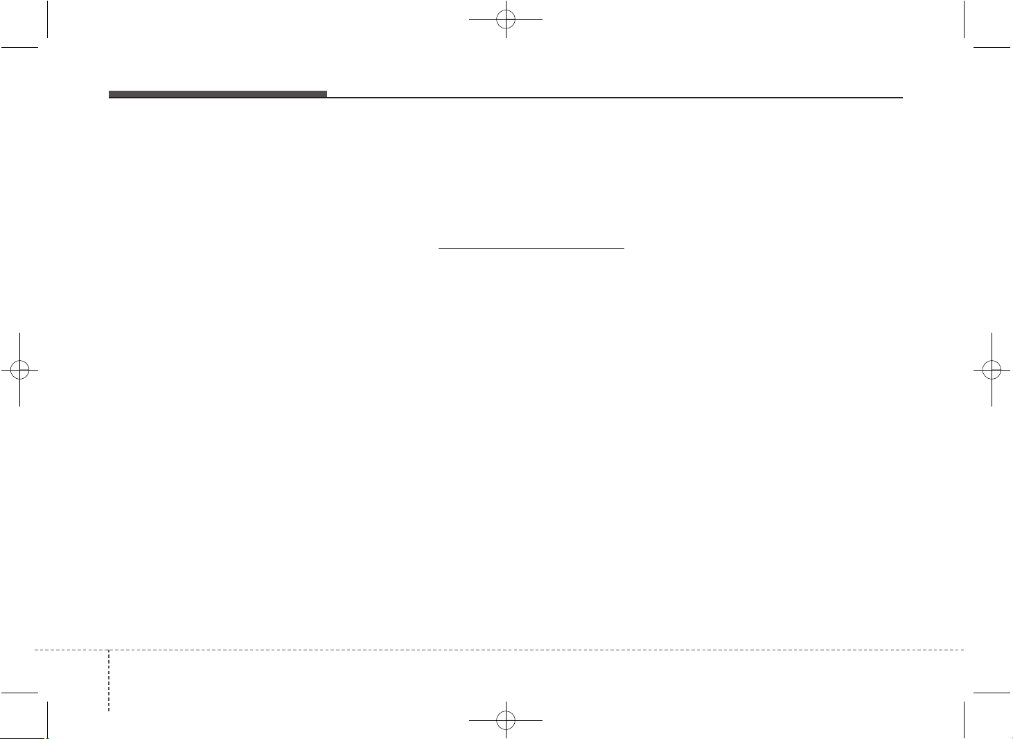
Maintenance
267
Brake hoses and lines
Visually check for proper installation,
chafing, cracks, deterioration and any
leakage. Replace any deteriorated or
damaged parts immediately.
Brake fluid
Check brake fluid level in the brake fluid
reservoir. The level should be between
“MIN” and “MAX” marks on the side of
the reservoir. Use only hydraulic brake
fluid conforming to DOT 3 or DOT 4
specification.
Brake pads, calipers and rotors
Check the pads for excessive wear, discs
for run out and wear, and calipers for fluid
leakage.
For more information on checking the
pads or lining wear limit, refer to the Kia
web site. (http://www
.kia-hotline.com)
Suspension mounting bolts
Check the suspension connections for
looseness or damage. Retighten to the
specified torque.
Parking brake
Inspect the parking brake system
including the EPB actuator, wiring
and connectors.
Steering gear box, linkage &
boots/lower arm ball joint
With the vehicle stopped and engine off,
check for excessive free-play in the
steering wheel.
Check the linkage for bends or damage.
Check the dust boots and ball joints for
deterioration, cracks, or damage.
Replace any damaged parts.
Drive shafts and boots
Check the drive shafts, boots and clamps
for cracks, deterioration, or damage.
Replace any damaged parts and, if nec-
essary, repack the grease.
Air conditioning refrigerant/
compressor (if equipped)
Check the air conditioning lines and con-
nections for leakage and damage.
JD PE eng 7.QXP 03.01.2017 17:17 Page 26
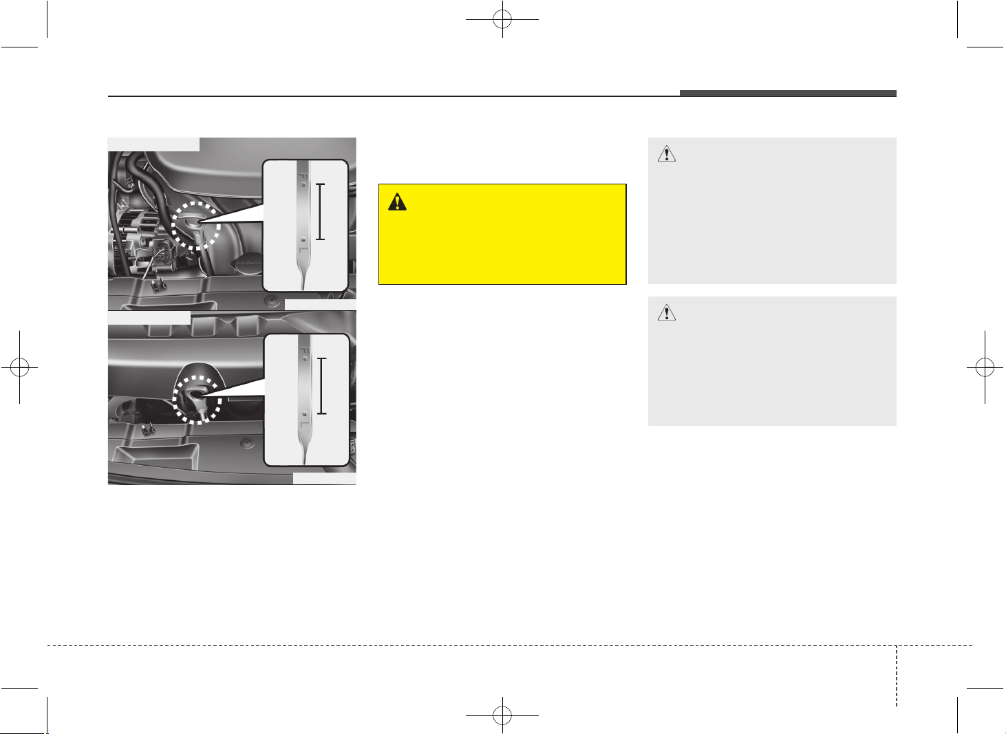
727
Maintenance
ENGINE OIL
Checking the engine oil level
1. Be sure the vehicle is on level ground.
2. Start the engine and allow it to reach
normal operating temperature.
3. Turn the engine off and wait for a few
minutes (about 5 minutes) for the oil to
return to the oil pan.
4. Pull the dipstick out, wipe it clean, and
re-insert it fully.
5. Pull the dipstick out again and check
the level. The level should be between
F and L.
WARNING - Radiator hose
Be very careful not to touch the
radiator hose when checking or
adding the engine oil as it may be
hot enough to burn you.
CAUTION - Diesel engine
Overfilling the engine oil may cause
severe dieseling due to churning
effect. It may lead to engine damage
accompanied with abrupt engine
speed increment, combustion noise
and white smoke emission.
CAUTION
• Do not overfill the engine oil. It
may damage the engine.
• Do not spill engine oil, when
adding or changing engine oil. If
you drop the engine oil on the
engine room, wipe it off immedi-
ately.
OGDE071003
■ Gasoline engine
OGD071004
■ Diesel engine
JD PE eng 7.QXP 03.01.2017 17:17 Page 27
Maintenance
287
If it is near or at L, add enough oil to bring
the level to F. Do not overfill.
Use a funnel to help prevent oil from
being spilled on engine components.
Use only the specified engine oil. (Refer
to “Recommended lubricants and capac-
ities” in chapter 8.)
Changing the engine oil and filter
We recommend that the engine oil and
filter be replaced by an authorized Kia
dealer.
WARNING
Used engine oil may cause irrita-
tion or cancer of the skin if left in
contact with the skin for prolonged
periods of time. Used engine oil
contains chemicals that have
caused cancer in laboratory ani-
mals. Always protect your skin by
washing your hands thoroughly
with soap and warm water as soon
as possible after handling used oil.
OGD071005
■ Gasoline engine
OGD071006
■ Diesel engine
JD PE eng 7.QXP 03.01.2017 17:17 Page 28
729
Maintenance
ENGINE COOLANT
The high-pressure cooling system has a
reservoir filled with year-round antifreeze
coolant. The reservoir is filled at the fac-
tory.
Check the antifreeze protection and
coolant concentration level at least once a
year, at the beginning of the winter season,
and before traveling to a colder climate.
Checking the coolant level
WARNING
Removing radiator
cap
• Never attempt to remove the radi-
ator cap while the engine is oper-
ating or hot. Doing so might lead
to cooling system and engine
damage and could result in seri-
ous personal injury from escap-
ing hot coolant or steam.
• Turn the engine off and wait until it
cools down. Use extreme care
when removing the radiator cap.
Wrap a thick towel around it, and
turn it counterclockwise slowly to
the first stop. Step back while the
pressure is released from the cool-
ing system. When you are sure all
the pressure has been released,
press down on the cap, using a
thick towel, and continue turning
counterclockwise to remove it.
(Continued)
(Continued)
• Even if the engine is not operat-
ing, do not remove the radiator
cap or the drain plug while the
engine and radiator are hot. Hot
coolant and steam may still blow
out under pressure, causing seri-
ous injury.
CAUTION
• When the engine overheats from
low engine coolant, suddenly
adding engine coolant may cause
cracks in the engine. To prevent
damage, add engine coolant
slowly in small quantities.
• Do not drive with no engine
coolant. It may cause water pump
failure and engine seizure, etc.
JD PE eng 7.QXP 03.01.2017 17:17 Page 29
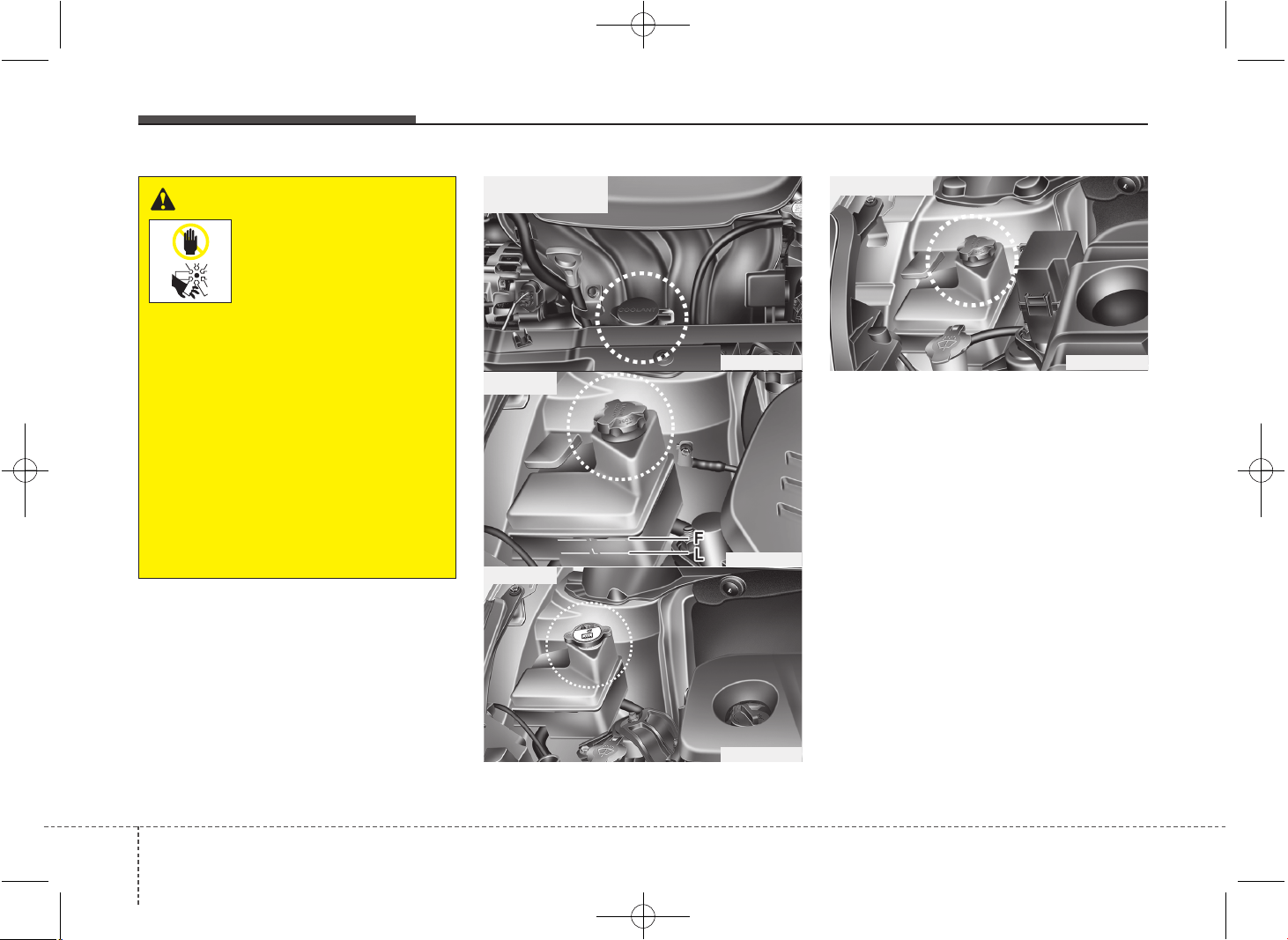
Maintenance
307
Check the condition and connections of
all cooling system hoses and heater
hoses. Replace any swollen or deterio-
rated hoses.
The coolant level should be filled
between F (MAX) and L (MIN) marks on
the side of the coolant reservoir when the
engine is cool.
If the coolant level is low, add enough
distilled (deionized) water. Bring the level
to F (MAX), but do not overfill. If frequent
coolant refill is required, we recommend
that the system be inspected by an
authorized Kia dealer.
OGD071007
■ Gasoline engine
• Type A
OJD073078
OJD075107L
• Type B
• Type C
WARNING
The electric motor (cool-
ing fan) is controlled by
engine coolant tempera-
ture, refrigerant pres-
sure and vehicle speed.
It may sometimes operate even
when the engine is not running.
Use extreme caution when working
near the blades of the cooling fan
so that you are not injured by a
rotating fan blades. As the engine
coolant temperature decreases, the
electric motor will automatically
shut off. This is a normal condition.
If your vehicle is equipped with
GDI, the electric motor (cooling fan)
may operate until you disconnect
the negative battery cable.
OGD071008
■ Diesel engine
JD PE eng 7.QXP 03.01.2017 17:17 Page 30
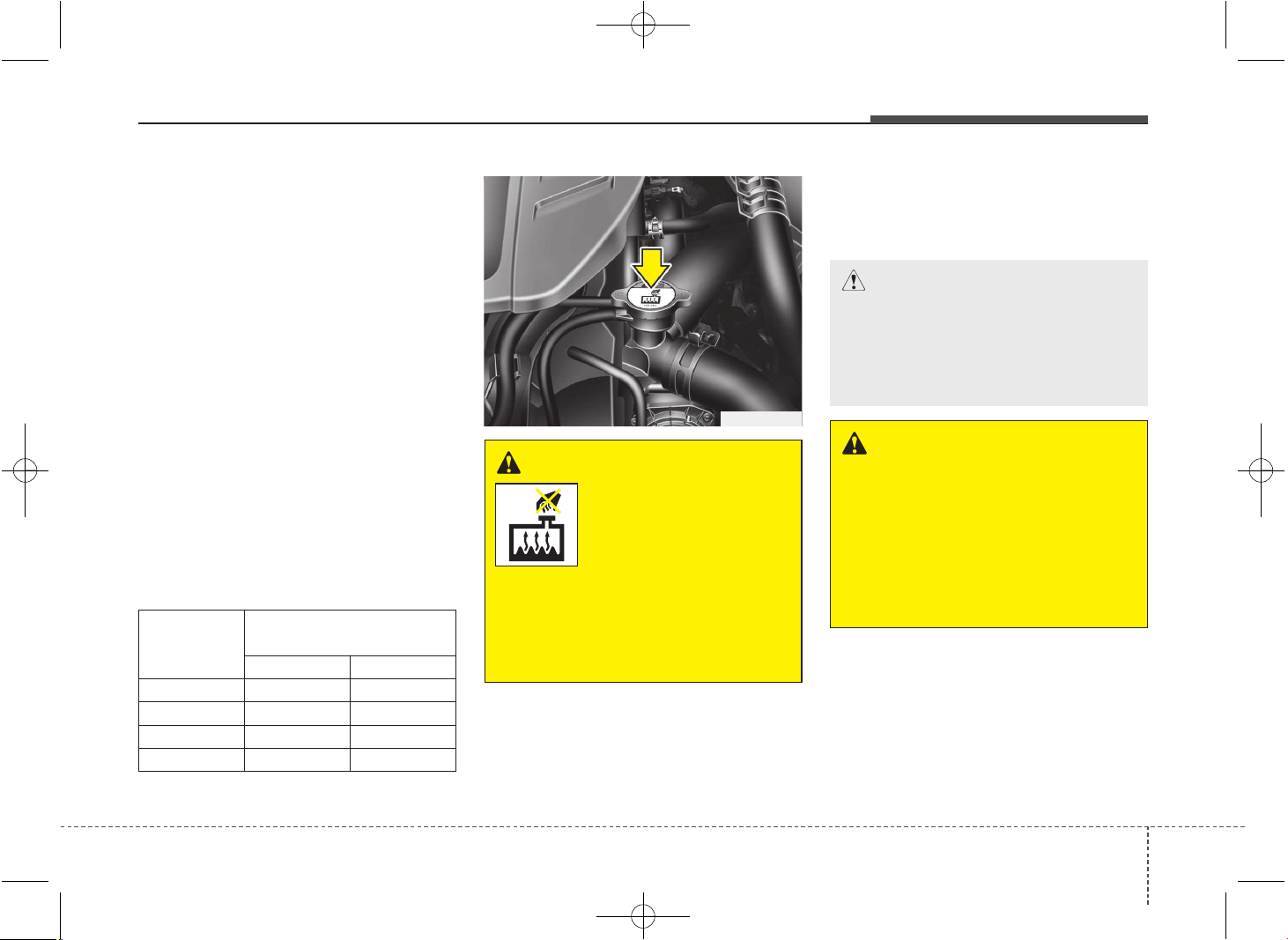
731
Maintenance
Recommended engine coolant
• When adding coolant, use only deion-
ized water or soft water for your vehicle
and never mix hard water in the
coolant filled at the factory. An improp-
er coolant mixture can result in serious
malfunction or engine damage.
• The engine in your vehicle has alu-
minum engine parts and must be pro-
tected by an ethylene-glycol with phos-
phate based coolant to prevent corro-
sion and freezing.
• DO NOT USE alcohol or methanol
coolant or mix them with the specified
coolant.
• Do not use a solution that contains
more than 60% antifreeze or less than
35% antifreeze, which would reduce
the effectiveness of the solution.
For mixture percentage, refer to the fol-
lowing table.
Changing the coolant
We recommend that the coolant be
replaced by an authorized Kia dealer.
WARNING
Radiator cap
Do not remove the radiator cap
when the engine and radiator are
hot. Scalding hot coolant and
steam may blow out under pres-
sure causing serious injury.
CAUTION
Put a thick cloth or fabric around
the radiator cap before refilling the
coolant in order to prevent the
coolant from overflowing into
engine parts such as generator.
WARNING - Coolant
• Do not use radiator coolant or
antifreeze in the washer fluid
reservoir.
• Radiator coolant can severely
obscure visibility when sprayed
on the windshield and may cause
loss of vehicle control or damage
to paint and body trim.
OJD073079
Ambient
Temperature
Mixture Percentage
(volume)
Antifreeze Water
-15°C (5°F) 35 65
-25°C (-13°F) 40 60
-35°C (-31°F) 50 50
-45°C (-49°F) 60 40
JD PE eng 7.QXP 03.01.2017 17:17 Page 31
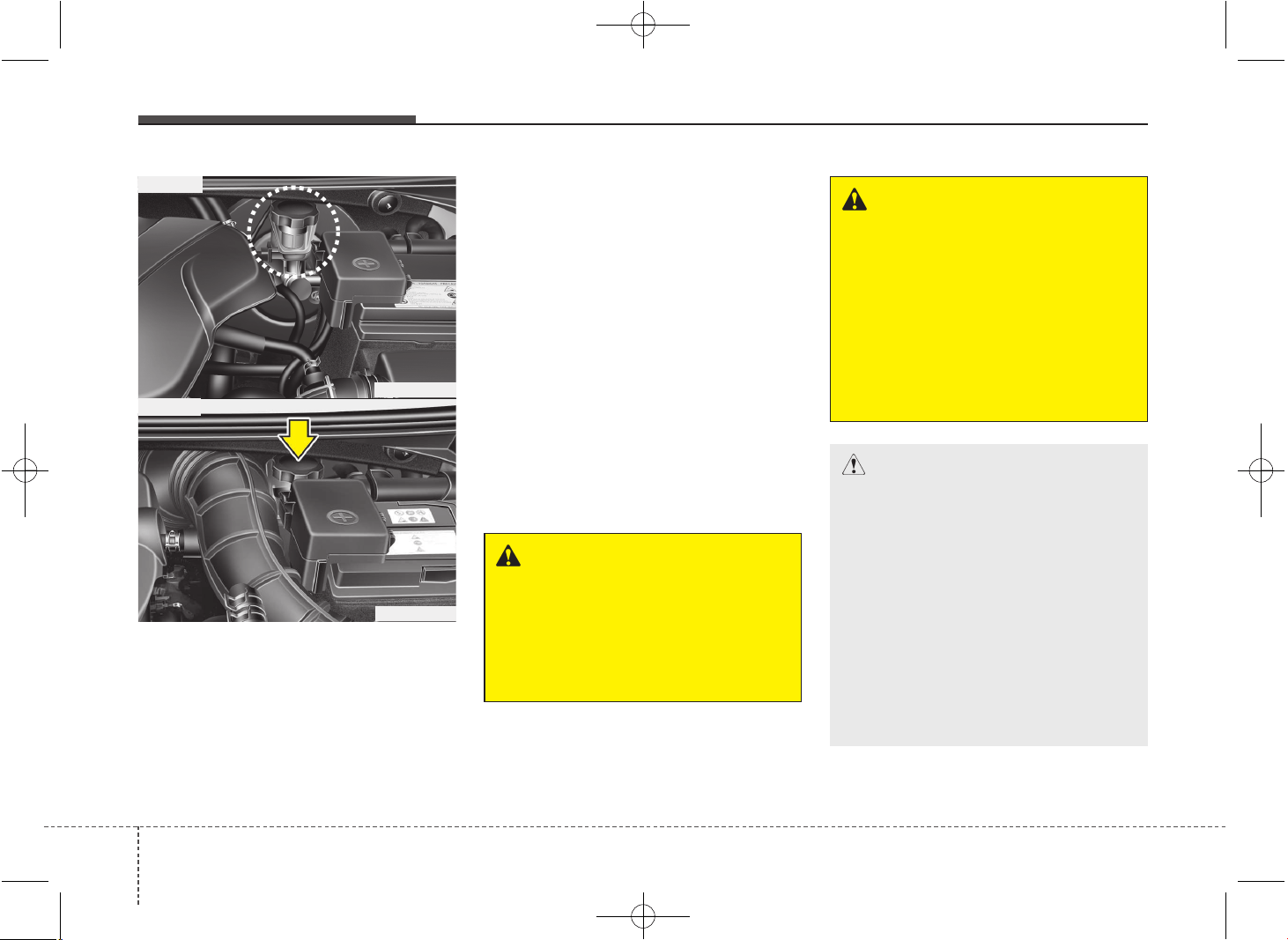
Maintenance
327
BRAKE/CLUTCH FLUID
Checking the brake/clutch fluid
level
Check the fluid level in the reservoir peri-
odically. The fluid level should be
between MAX and MIN marks on the
side of the reservoir.
Before removing the reservoir cap and
adding brake/clutch fluid, clean the area
around the reservoir cap thoroughly to
prevent brake/clutch fluid contamination.
If the level is low, add fluid to the MAX
level. The level will fall with accumulated
mileage. This is a normal condition asso-
ciated with the wear of the brake linings.
If the fluid level is excessively low, we
recommend that the system be checked
by an authorized Kia dealer.
Use only the specified brake/clutch fluid.
(Refer to “Recommended lubricants and
capacities” in chapter 8.)
Never mix different types of fluid.
WARNING - Brake/clutch
fluid
When changing and adding
brake/clutch fluid, handle it careful-
ly. Do not let it come in contact with
your eyes. If brake/clutch fluid
should come in contact with your
eyes, immediately flush them with a
large quantity of fresh tap water.
Have your eyes examined by a doc-
tor as soon as possible.
WARNING - Loss of
brake/clutch fluid
In the event the brake/clutch sys-
tem requires frequent additions of
fluid, we recommend that the sys-
tem be inspected by an authorized
Kia dealer.
CAUTION
Do not allow brake/clutch fluid to
contact the vehicle's body paint, as
paint damage will result.
Brake/clutch fluid, which has been
exposed to open air for an extended
time should never be used as its
quality cannot be guaranteed. It
should be disposed of properly.
Don't put in the wrong kind of fluid.
A few drops of mineral-based oil,
such as engine oil, in your
brake/clutch system can damage
brake/clutch system parts.
OGD071009
■ Type A
OJD073083
■ Type B
JD PE eng 7.QXP 03.01.2017 17:17 Page 32
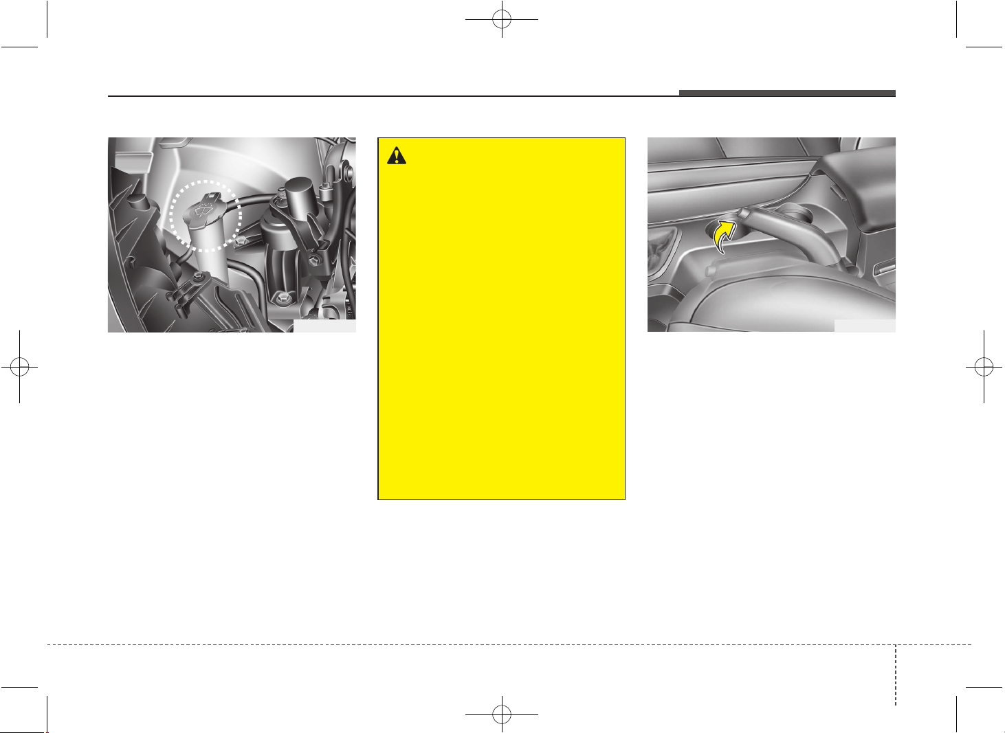
733
Maintenance
WASHER FLUID
Checking the washer fluid level
Check the fluid level in the washer fluid
reservoir and add fluid if necessary.
Plain water may be used if washer fluid is
not available. However, use washer sol-
vent with antifreeze characteristics in
cold climates to prevent freezing.
Checking the parking brake
Check the stroke of the parking brake by
counting the number of “clicks’’ heard
while fully applying it from the released
position. Also, the parking brake alone
should securely hold the vehicle on a fair-
ly steep grade. If the stroke is more or
less than specified, we recommend that
the system be serviced by an authorized
Kia dealer.
Stroke : 6~8 “clicks’’ at a force of
20 kg (44 lbs, 196 N).
OGD071010
WARNING - Coolant
• Do not use radiator coolant or
antifreeze in the washer fluid
reservoir.
• Radiator coolant can severely
obscure visibility when sprayed
on the windshield and may cause
loss of vehicle control or damage
to paint and body trim.
• Windshield Washer fluid agents
contain some amounts of alcohol
and can be flammable under cer-
tain circumstances. Do not allow
sparks or flame to contact the
washer fluid or the washer fluid
reservoir. Damage to the vehicle
or occupants could occur.
• Windshield washer fluid is poi-
sonous to humans and animals.
Do not drink and avoid contacting
windshield washer fluid. Serious
injury or death could occur.
PARKING BRAKE - HAND TYPE
OJD052010
JD PE eng 7.QXP 03.01.2017 17:18 Page 33
Maintenance
347
FUEL FILTER (FOR DIESEL)
Draining water from fuel filter
The fuel filter for diesel engine plays an
important role of separating water from
fuel and accumulating the water in its
bottom.
If water accumulates in the fuel filter, the
warning light comes on when the ignition
switch is in the ON position.
If this warning light illuminates,
we recommend that the system
be serviced by an authorized
Kia dealer.
Fuel filter cartridge replacement
We recommend the fuel filter cartridge
be replaced by an authorized Kia dealer
according to the Maintenance Schedule
at the beginning of this chapter.
CAUTION
If the water accumulated in the fuel
filter is not drained at proper times,
damages to the major parts such as
the fuel system can be caused by
water permeation in the fuel filter.
JD PE eng 7.QXP 03.01.2017 17:18 Page 34
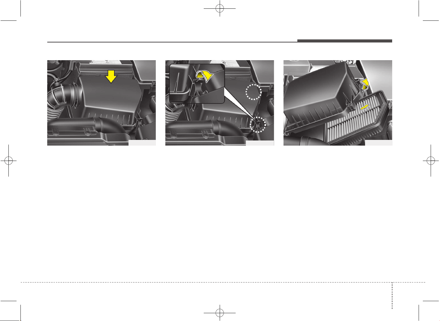
735
Maintenance
AIR CLEANER
Filter replacement
It must be replaced when necessary, and
should not be washed.
You can clean the filter when inspecting
the air cleaner element.
Clean the filter by using compressed air.
1. Loosen the air cleaner cover attaching
clips and open the cover.
2. Wipe the inside of the air cleaner.
3. Replace the air cleaner filter.
4. Lock the cover with the cover attaching
clips.
OMD070011
OMD070010 OMD070012
JD PE eng 7.QXP 03.01.2017 17:18 Page 35
Maintenance
367
Replace the filter according to the
Maintenance Schedule.
If the vehicle is operated in extremely
dusty or sandy areas, replace the ele-
ment more often than the usual recom-
mended intervals. (Refer to
“Maintenance under severe usage condi-
tions” in this chapter.)
CAUTION
• Do not drive with the air cleaner
removed; this will result in exces-
sive engine wear.
• When removing the air cleaner fil-
ter, be careful that dust or dirt
does not enter the air intake, or
damage may result.
• We recommend that you use
parts for replacement from an
authorized Kia dealer.
JD PE eng 7.QXP 03.01.2017 17:18 Page 36
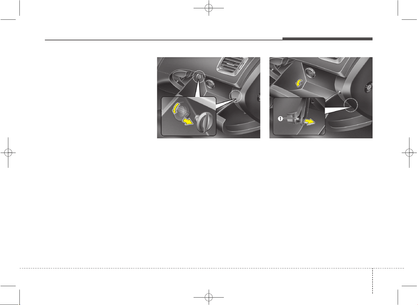
737
Maintenance
CLIMATE CONTROL AIR FILTER
Filter inspection
If the vehicle is operated in the severely
air-polluted cities or on dusty rough
roads for a long period, it should be
inspected more frequently and replaced
earlier. When you, the owner, replace the
climate control air filter, replace it per-
forming the following procedure, and be
careful to avoid damaging other compo-
nents.
Replace the filter according to the main-
tenance Schedule.
Filter replacement
1. With the glove box open, remove the
stoppers on both sides.
2. Open the glove box and remove the
support strap (1).
OJD072013OJD072012
JD PE eng 7.QXP 03.01.2017 17:18 Page 37
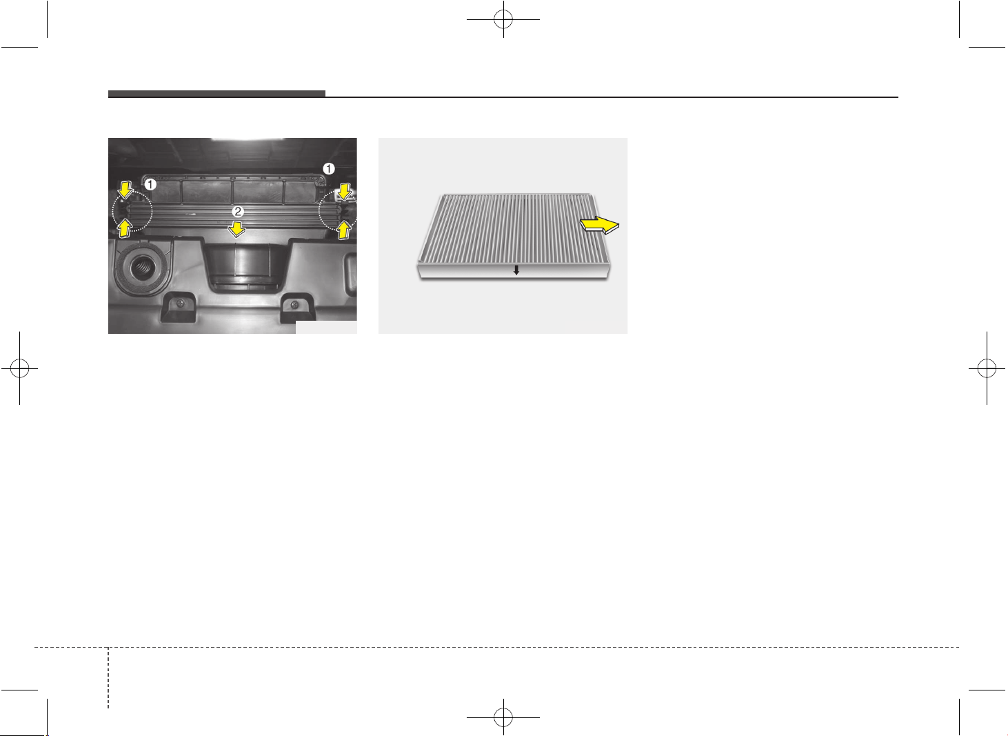
Maintenance
387
3. Remove the cover while pressing the
lock on both side of the cover and
remove the climate control air filter.
4. Replace the climate control air filter.
5. Reassemble in the reverse order of
disassembly.
✽✽
NOTICE
When replacing the climate control air
filter install it properly. Otherwise, the
system may produce noise and the effec-
tiveness of the filter may be reduced.
OVG079016OJD072014
JD PE eng 7.QXP 03.01.2017 17:18 Page 38
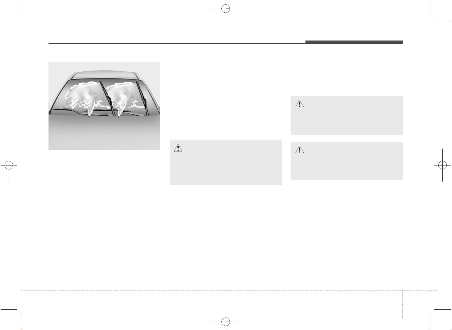
739
Maintenance
WIPER BLADES
Blade inspection
✽✽
NOTICE
Commercial hot waxes applied by auto-
matic car washes have been known to
make the windshield difficult to clean.
Contamination of either the windshield or
the wiper blades with foreign matter can
reduce the effectiveness of the wind-
shield wipers. Common sources of con-
tamination are insects, tree sap, and hot
wax treatments used by some commer-
cial car washes. If the blades are not wip-
ing properly, clean both the window and
the blades with a good cleaner or mild
detergent, and rinse thoroughly with
clean water.
Blade replacement
When the wipers no longer clean ade-
quately, the blades may be worn or
cracked, and require replacement.
CAUTION
To prevent damage to the wiper
blades, do not use gasoline,
kerosene, paint thinner, or other
solvents on or near them.
CAUTION
To prevent damage to the wiper arms
or other components, do not attempt
to move the wipers manually.
CAUTION
The use of a non-specified wiper
blade could result in wiper malfunc-
tion and failure.
1JBA5122
JD PE eng 7.QXP 03.01.2017 17:18 Page 39
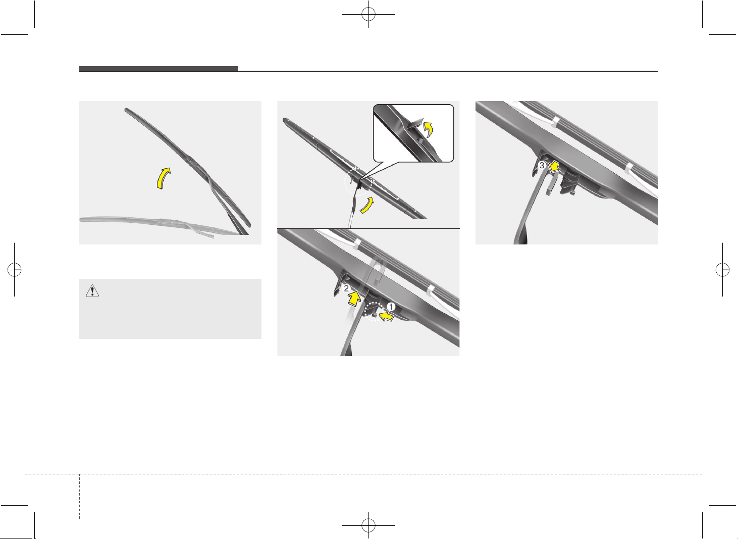
Maintenance
407
Front windshield wiper blade
1. Raise the wiper arm.
2. Turn the wiper blade clip. Then lift up
the blade clip.
3. Push the clip (1) and push up the
wiper arm (2).
4. Push down the wiper arm (3) and
install the new blade assembly in the
reverse order of removal.
5. Return the wiper arm on the wind-
shield.
CAUTION
Do not allow the wiper arm to fall
against the windshield, since it may
chip or crack the windshield.
OHM078059
OSBL071001
OSBL071003
OSBL071002
JD PE eng 7.QXP 03.01.2017 17:18 Page 40
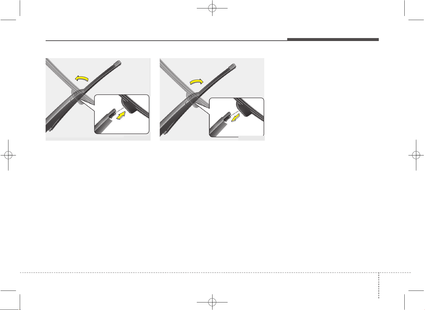
741
Maintenance
Rear window wiper blade
1. Raise the wiper arm and pull out the
wiper blade assembly.
2. Install the new blade assembly by
inserting the center part into the slot in
the wiper arm until it clicks into place.
3. Make sure the blade assembly is
installed firmly by trying to pull it slightly.
To prevent damage to the wiper arms or
other components, we recommend that
the wiper blade be replaced by an
authorized Kia dealer.
OGD071041 OGD071042
JD PE eng 7.QXP 03.01.2017 17:18 Page 41
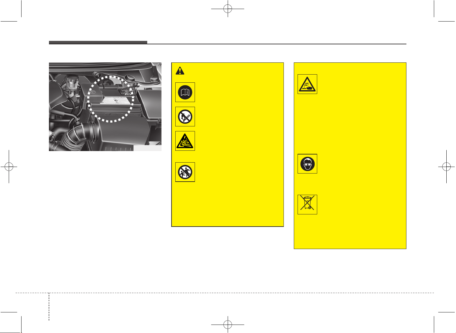
Maintenance
427
BATTERY
For best battery service
• Keep the battery securely mounted.
• Keep the battery top clean and dry.
• Keep the terminals and connections
clean, tight, and coated with petroleum
jelly or terminal grease.
• Rinse any spilled electrolyte from the
battery immediately with a solution of
water and baking soda.
• If the vehicle is not going to be used for
an extended time, disconnect the bat-
tery cables.
WARNING - Battery
dangers
Always read the following
instructions carefully when
handling a battery.
Keep lighted cigarettes and
all other flames or sparks
away from the battery.
Hydrogen, a highly com-
bustible gas, is always
present in battery cells and
may explode if ignited.
Keep batteries out of the
reach of children because
batteries contain highly
corrosive SULFURIC ACID.
Do not allow battery acid to
contact your skin, eyes,
clothing or paint finish.
(Continued)
OGD071015
(Continued)
If any electrolyte gets into
your eyes, flush your eyes
with clean water for at least
15 minutes and get immedi-
ate medical attention.
If electrolyte gets on your
skin, thoroughly wash the
contacted area. If you feel a
pain or a burning sensa-
tion, get medical attention
immediately.
Wear eye protection when
charging or working near a
battery. Always provide
ventilation when working in
an enclosed space.
An inappropriately disposed
battery can be harmful to
the environment and human
health. Dispose the battery
according to your local
law(s) or regulation.
(Continued)
Pb
JD PE eng 7.QXP 03.01.2017 17:18 Page 42
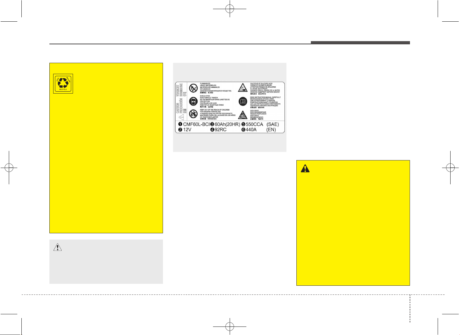
743
Maintenance
❈ The actual battery label in the vehicle may
differ from the illustration.
Battery capacity label
(see the example)
1. CMF60L-BCI : The Kia model name of
battery
2. 12V : The nominal voltage
3. 60Ah(20HR) : The nominal capacity
(in Ampere hours)
4. 92RC : The nominal reserve capacity
(in min.)
5. 550CCA : The cold-test current in
amperes by SAE
6. 440A : The cold-test current in amperes
by EN
Battery recharging
Your vehicle has a maintenance-free,
calcium-based battery.
• If the battery becomes discharged in a
short time (because, for example, the
headlights or interior lights were left on
while the vehicle was not in use),
recharge it by slow charging (trickle)
for 10 hours.
• If the battery gradually discharges
because of high electric load while the
vehicle is being used, recharge it at 20-
30A for two hours.
(Continued)
The battery contains lead.
Do not dispose of it after
use. Please return the bat-
tery to an authorized Kia
dealer to be recycled.
• When lifting a plastic-cased bat-
tery, excessive pressure on the
case may cause battery acid to
leak, resulting in personal injury.
Lift with a battery carrier or with
your hands on opposite corners.
• Never attempt to recharge the
battery when the battery cables
are connected.
• The electrical ignition system
works with high voltage. Never
touch these components with the
engine running or the ignition
switched on.
Failure to follow the above warn-
ings can result in serious bodily
injury or death.
CAUTION
If you use unauthorized electronic
devices, the battery may be dis-
charged. Never use unauthorized
devices.
OJD072039
WARNING - Recharging
battery
When recharging the battery,
observe the following precautions:
• The battery must be removed
from the vehicle and placed in an
area with good ventilation.
• Do not allow cigarettes, sparks,
or flame near the battery.
• Watch the battery during charg-
ing, and stop or reduce the charg-
ing rate if the battery cells begin
gassing (boiling) violently or if
the temperature of the electrolyte
of any cell exceeds 49°C (120°F).
(Continued)
■ Example
JD PE eng 7.QXP 03.01.2017 17:18 Page 43
Maintenance
447
Reset items
Items should be reset after the battery
has been discharged or the battery has
been disconnected.
• Auto up/down window (See chapter 4)
• Sunroof (See chapter 4)
• Trip computer (See chapter 4)
• Climate control system
(See chapter 4)
• Audio (See chapter 4)
(Continued)
• Wear eye protection when check-
ing the battery during charging.
• Disconnect the battery charger in
the following order.
1. Turn off the battery charger
main switch.
2. Unhook the negative clamp
from the negative battery ter-
minal.
3. Unhook the positive clamp
from the positive battery termi-
nal.
• Before performing maintenance
or recharging the battery, turn off
all accessories and stop the
engine.
• The negative battery cable must
be removed first and installed
last when the battery is discon-
nected.
JD PE eng 7.QXP 03.01.2017 17:19 Page 44
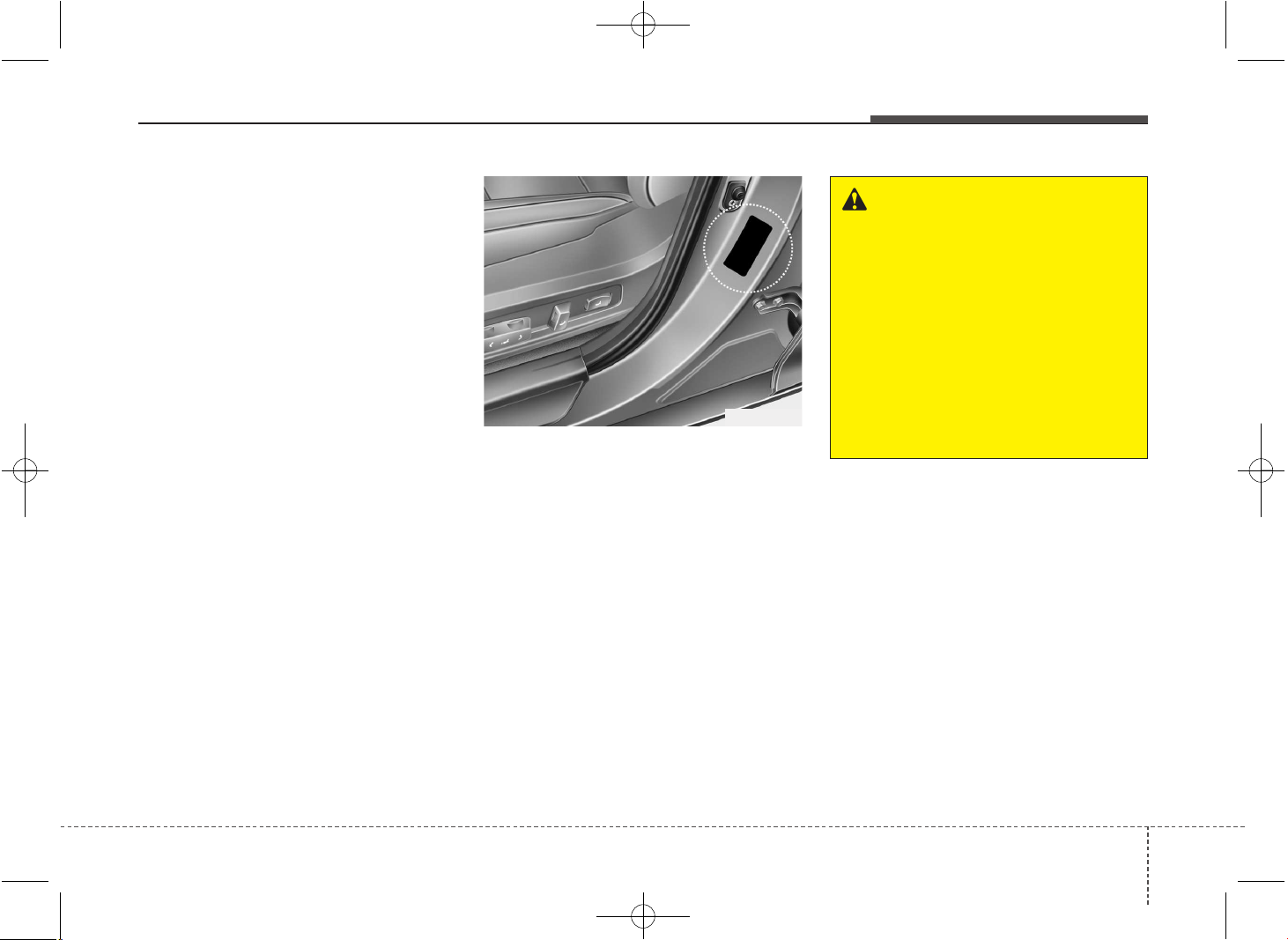
745
Maintenance
TIRES AND WHEELS
Tire care
For proper maintenance, safety, and
maximum fuel economy, you must
always maintain recommended tire
inflation pressures and stay within
the load limits and weight distribution
recommended for your vehicle.
Recommended cold tire inflation
pressures
All tire pressures (including the
spare) should be checked when the
tires are cold. “Cold Tires” means the
vehicle has not been driven for at
least three hours or driven less than
1.6 km (1 mile).
Recommended pressures must be
maintained for the best ride, top vehi-
cle handling, and minimum tire wear.
For recommended inflation pressure
refer to “Tire and wheels” in chapter 8.
All specifications (sizes and pres-
sures) can be found on a label
attached to the vehicle.
WARNING - Tire underin-
flation
Severe underinflation (70 kPa
(10 psi) or more) can lead to
severe heat build-up, causing
blowouts, tread separation and
other tire failures that can result
in the loss of vehicle control
leading to severe injury or
death. This risk is much higher
on hot days and when driving
for long periods at high speeds.
OJD082005
JD PE eng 7.QXP 03.01.2017 17:19 Page 45
Maintenance
467
WARNING - Tire inflation
Overinflation or underinflation
can reduce tire life, adversely
affect vehicle handling, and
lead to sudden tire failure. This
could result in loss of vehicle
control and potential injury.
CAUTION - Tire pressure
Always observe the following:
• Check tire pressure when the
tires are cold. (After vehicle
has been parked for at least
three hours or hasn't been
driven more than 1.6 km (1
mile) since startup.)
• Check the pressure of your
spare tire each time you check
the pressure of other tires.
• Never overload your vehicle.
Be careful not to overload a
vehicle luggage rack if your
vehicle is equipped with one.
• Worn, old tires can cause acci-
dents. If your tread is badly
worn, or if your tires have
been damaged, replace them.
CAUTION
• Underinflation also results in
excessive wear, poor handling
and reduced fuel economy.
Wheel deformation also is
possible. Keep your tire pres-
sures at the proper levels. If a
tire frequently needs refilling,
we recommend that the sys-
tem be checked by an author-
ized Kia dealer.
• Overinflation produces a
harsh ride, excessive wear at
the center of the tire tread, and
a greater possibility of dam-
age from road hazards.
CAUTION
• Warm tires normally exceed
recommended cold tire pres-
sures by 28 to 41 kPa (4 to 6
psi). Do not release air from
warm tires to adjust the pres-
sure or the tires will be under-
inflated.
• Be sure to reinstall the tire
inflation valve caps. Without
the valve cap, dirt or moisture
could get into the valve core
and cause air leakage. If a
valve cap is missing, install a
new one as soon as possible.
JD PE eng 7.QXP 03.01.2017 17:19 Page 46
747
Maintenance
Checking tire inflation pressure
Check your tires once a month or
more.
Also, check the tire pressure of the
spare tire.
How to check
Use a good quality gauge to check
tire pressure. You can not tell if your
tires are properly inflated simply by
looking at them. Radial tires may
look properly inflated even when
they're underinflated.
Check the tire's inflation pressure
when the tires are cold. - "Cold"
means your vehicle has been sitting
for at least three hours or driven no
more than 1.6 km (1 mile).
Remove the valve cap from the tire
valve stem. Press the tire gauge firm-
ly onto the valve to get a pressure
measurement. If the cold tire inflation
pressure matches the recommended
pressure on the tire and loading
information label, no further adjust-
ment is necessary. If the pressure is
low, add air until you reach the rec-
ommended amount.
If you overfill the tire, release air by
pushing on the metal stem in the
center of the tire valve. Recheck the
tire pressure with the tire gauge. Be
sure to put the valve caps back on
the valve stems. They help prevent
leaks by keeping out dirt and mois-
ture.
WARNING
• Inspect your tires frequently
for proper inflation as well as
wear and damage. Always use
a tire pressure gauge.
• Tires with too much or too little
pressure wear unevenly caus-
ing poor handling, loss of vehi-
cle control, and sudden tire
failure leading to accidents,
injuries, and even death. The
recommended cold tire pres-
sure for your vehicle can be
found in this manual and on
the tire label located on the dri-
ver's side center pillar.
• Worn tires can cause acci-
dents. Replace tires that are
worn, show uneven wear, or
are damaged.
• Remember to check the pres-
sure of your spare tire. Kia
recommends that you check
the spare every time you
check the pressure of the
other tires on your vehicle.
JD PE eng 7.QXP 03.01.2017 17:19 Page 47
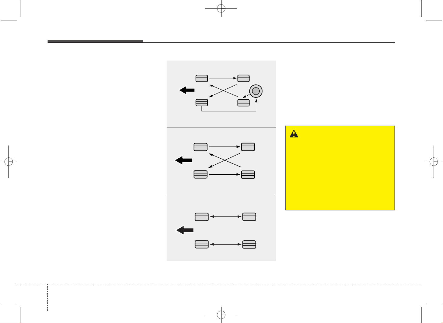
Maintenance
487
Tire rotation
To equalize tread wear, it is recom-
mended that the tires be rotated
every 12,000 km (7,500 miles) or
sooner if irregular wear develops.
During rotation, check the tires for
correct balance.
When rotating tires, check for uneven
wear and damage. Abnormal wear is
usually caused by incorrect tire pres-
sure, improper wheel alignment, out-
of-balance wheels, severe braking or
severe cornering. Look for bumps or
bulges in the tread or side of tire.
Replace the tire if you find either of
these conditions. Replace the tire if
fabric or cord is visible. After rotation,
be sure to bring the front and rear tire
pressures to specification and check
lug nut tightness.
Refer to “Tire and wheels” in chapter
8.
Disc brake pads should be inspected
for wear whenever tires are rotated.
✽✽
NOTICE
Rotate radial tires that have an
asymmetric tread pattern only from
front to rear and not from right to
left.
WARNING
• Do not use the compact spare
tire for tire rotation.
• Do not mix bias ply and radial
ply tires under any circum-
stances. This may cause
unusual handling characteris-
tics that could result in death,
severe injury, or property
damage.
S2BLA790
S2BLA790A
CBGQ0707A
■ Without a spare tire
■ With a full-size spare tire (if equipped)
■ Directional tires (if equipped)
JD PE eng 7.QXP 03.01.2017 17:19 Page 48
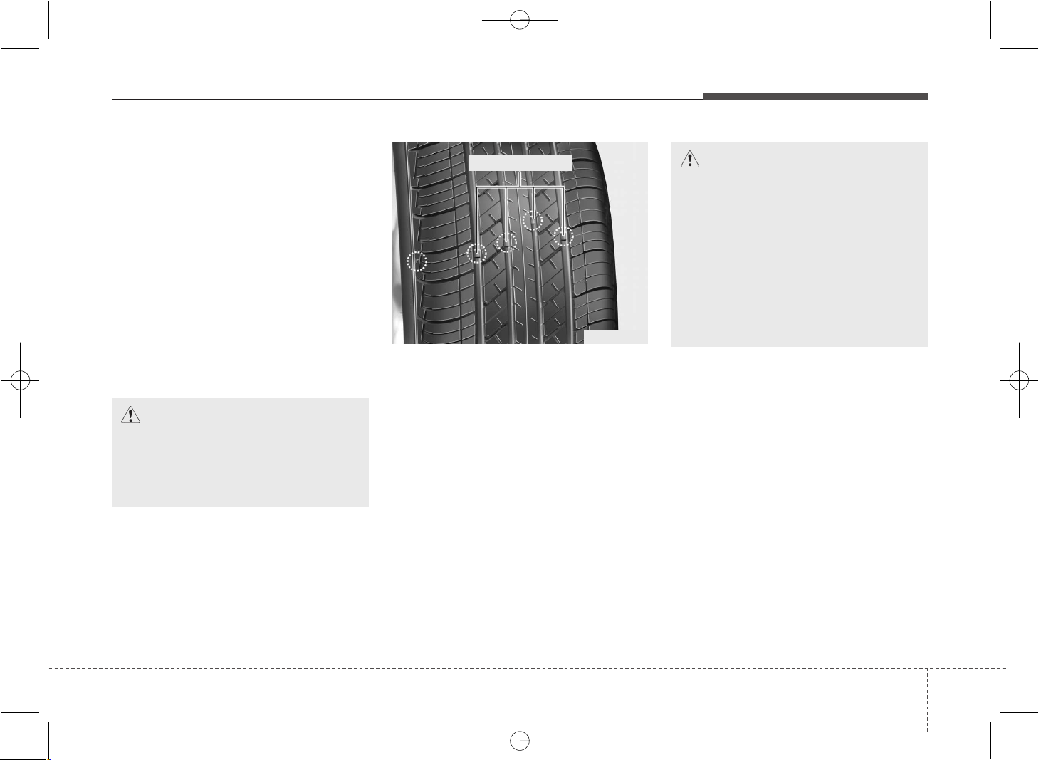
749
Maintenance
Wheel alignment and tire balance
The wheels on your vehicle were
aligned and balanced carefully at the
factory to give you the longest tire life
and best overall performance.
In most cases, you will not need to
have your wheels aligned again.
However, if you notice unusual tire
wear or your vehicle pulling one way
or the other, the alignment may need
to be reset.
If you notice your vehicle vibrating
when driving on a smooth road, your
wheels may need to be rebalanced.
Tire replacement
If the tire is worn evenly, a tread wear
indicator will appear as a solid band
across the tread. This shows there is
less than 1.6 mm (1/16 in.) of tread
left on the tire. Replace the tire when
this happens.
Do not wait for the band to appear
across the entire tread before replac-
ing the tire.
✽✽
NOTICE
We recommend that when replacing
tires, use the same originally sup-
plied with the vehicles.
If not, that affects driving perform-
ance.
CAUTION
Improper wheel weights can
damage your vehicle's alu-
minum wheels. Use only
approved wheel weights.
CAUTION
When replacing the tires,
recheck and tighten the wheel
nuts after driving about 1,000 km
(620miles). If the steering wheel
shakes or the vehicle vibrates
while driving, the tire is out of
balance. Align the tire balance. If
the problem is not solved, we
recommend that you contact an
authorized kia dealer.
OEN076053
Tread wear indicator
JD PE eng 7.QXP 03.01.2017 17:19 Page 49
Maintenance
507
Compact spare tire replacement
(if equipped)
A compact spare tire has a shorter
tread life than a regular size tire.
Replace it when you can see the
tread wear indicator bars on the tire.
The replacement compact spare tire
should be the same size and design
tire as the one provided with your
new vehicle and should be mounted
on the same compact spare tire
wheel. The compact spare tire is not
designed to be mounted on a regular
size wheel, and the compact spare
tire wheel is not designed for mount-
ing a regular size tire.
(Continued)
• The use of any other tire size or
type may seriously affect ride,
handling, ground clearance,
stopping distance, body to tire
clearance, snow tire clearance,
and speedometer reliability.
• It is best to replace all four tires
at the same time. If that is not
possible, or necessary, then
replace the two front or two
rear tires as a pair. Replacing
just one tire can seriously
affect your vehicle’s handling.
• The ABS works by comparing
the speed of the wheels. Tire
size can affect wheel speed.
When replacing tires, all 4
tires must use the same size
originally supplied with the
vehicle. Using tires of a differ-
ent size can cause the ABS
(Anti-lock Brake System) and
ESC (Electronic Stability
Control) to work irregularly.
WARNING - Replacing
tires
• Driving on worn-out tires is
very hazardous and will reduce
braking effectiveness, steering
accuracy, and traction.
• Your vehicle is equipped with
tires designed to provide for
safe ride and handling capa-
bility. Do not use a size and
type of tire and wheel that is
different from the one that is
originally installed on your
vehicle. It can affect the safety
and performance of your vehi-
cle, which could lead to han-
dling failure or rollover and
serious injury. When replacing
the tires, be sure to equip all
four tires with the tire and
wheel of the same size, type,
tread, brand and load-carrying
capacity.
(Continued)
JD PE eng 7.QXP 03.01.2017 17:19 Page 50
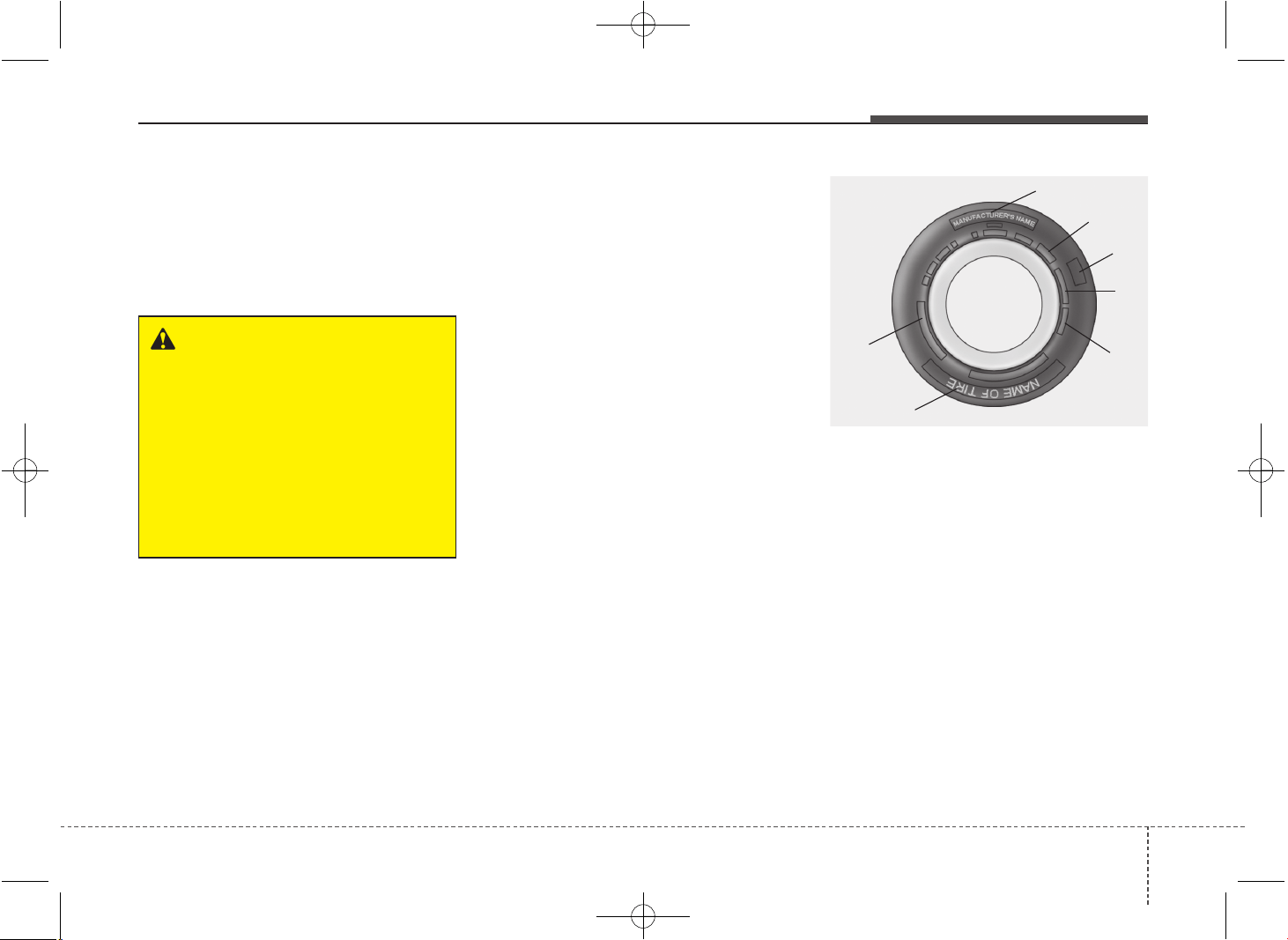
751
Maintenance
Wheel replacement
When replacing the metal wheels for
any reason, make sure the new
wheels are equivalent to the original
factory units in diameter, rim width
and offset.
Tire traction
Tire traction can be reduced if you
drive on worn tires, tires that are
improperly inflated or on slippery
road surfaces. Tires should be
replaced when tread wear indicators
appear. To reduce the possibility of
losing control, slow down whenever
there is rain, snow or ice on the road.
Tire maintenance
In addition to proper inflation, correct
wheel alignment helps to decrease
tire wear. If you find a tire is worn
unevenly, have your dealer check the
wheel alignment.
When you have new tires installed,
make sure they are balanced. This
will increase vehicle ride comfort and
tire life. Additionally, a tire should
always be rebalanced if it is removed
from the wheel.
Tire sidewall labeling
This information identifies and
describes the fundamental charac-
teristics of the tire and also provides
the tire identification number (TIN)
for safety standard certification. The
TIN can be used to identify the tire in
case of a recall.
1. Manufacturer or brand name
Manufacturer or Brand name is
shown.
I030B04JM
1
1
2
3
4
5,6
7
WARNING
A wheel that is not the correct
size may adversely affect wheel
and bearing life, braking and
stopping abilities, handling char-
acteristics, ground clearance,
body-to-tire clearance, snow
chain clearance, speedometer
and odometer calibration, head-
light aim and bumper height.
JD PE eng 7.QXP 03.01.2017 17:19 Page 51

Maintenance
527
2. Tire size designation
A tire’s sidewall is marked with a tire
size designation. You will need this
information when selecting replace-
ment tires for your car. The following
explains what the letters and numbers
in the tire size designation mean.
Example tire size designation:
(These numbers are provided as an
example only; your tire size designa-
tor could vary depending on your
vehicle.)
195/65R15 91H
P - Applicable vehicle type (tires
marked with the prefix “P’’ are
intended for use on passenger
vehicles or light trucks; however,
not all tires have this marking).
195 - Tire width in millimeters.
65 - Aspect ratio. The tire’s chapter
height as a percentage of its
width.
R - Tire construction code (Radial).
15 - Rim diameter in inches.
91 - Load Index, a numerical code
associated with the maximum
load the tire can carry.
H - Speed Rating Symbol. See the
speed rating chart in this chapter
for additional information.
Wheel size designation
Wheels are also marked with impor-
tant information that you need if you
ever have to replace one. The follow-
ing explains what the letters and
numbers in the wheel size designa-
tion mean.
Example wheel size designation:
6.0JX15
6.0 - Rim width in inches.
J - Rim contour designation.
15 - Rim diameter in inches.
Tire speed ratings
The chart below lists many of the dif-
ferent speed ratings currently being
used for passenger cars. The speed
rating is part of the tire size designa-
tion on the sidewall of the tire. This
symbol corresponds to that tire's
designed maximum safe operating
speed.
S 180 km/h (112 mph)
T 190 km/h (118 mph)
H 210 km/h (130 mph)
V 240 km/h (149 mph)
W 270 km/h (167 mph)
Y 300 km/h (186 mph)
Maximum Speed
Speed
Rating
Symbol
JD PE eng 7.QXP 03.01.2017 17:19 Page 52
753
Maintenance
3. Checking tire life
(TIN : Tire Identification Number)
Any tires that are over 6 years, based
on the manufacturing date, tire
strength and performance, decline
with age naturally (even unused
spare tires). Therefore, the tires
(including the spare tire) should be
replaced by new ones. You can find
the manufacturing date on the tire
sidewall (possibly on the inside of the
wheel), displaying the DOT Code.
The DOT Code is a series of num-
bers on a tire consisting of numbers
and English letters. The manufactur-
ing date is designated by the last four
digits (characters) of the DOT code.
DOT : XXXX XXXX OOOO
The front part of the DOT means a
plant code number, tire size and tread
pattern and the last four numbers indi-
cate week and year manufactured.
For example:
DOT XXXX XXXX 1617 represents
that the tire was produced in the 16th
week of 2017.
4. Tire ply composition and material
The number of layers or plies of rub-
ber-coated fabric are in the tire. Tire
manufacturers also must indicate the
materials in the tire, which include
steel, nylon, polyester, and others.
The letter "R" means radial ply con-
struction; the letter "D" means diago-
nal or bias ply construction; and the
letter "B" means belted-bias ply con-
struction.
5. Maximum permissible inflation
pressure
This number is the greatest amount
of air pressure that should be put in
the tire. Do not exceed the maximum
permissible inflation pressure. Refer
to the Tire and Loading Information
label for recommended inflation
pressure.
6. Maximum load rating
This number indicates the maximum
load in kilograms and pounds that can
be carried by the tire. When replacing
the tires on the vehicle, always use a
tire that has the same load rating as
the factory installed tire.
WARNING - Tire age
Tires degrade over time, even
when they are not being used.
Regardless of the remaining
tread, it is recommended that
tires generally be replaced after
six (6) years of normal service.
Heat caused by hot climates or
frequent high loading condi-
tions can accelerate the aging
process. Failure to follow this
Warning can result in sudden
tire failure, which could lead to
a loss of control and an acci-
dent involving serious injury or
death.
JD PE eng 7.QXP 03.01.2017 17:19 Page 53
Maintenance
547
7. Uniform tire quality grading
Quality grades can be found where
applicable on the tire sidewall
between tread shoulder and maxi-
mum chapter width.
For example:
TREADWEAR 200
TRACTION AA
TEMPERATURE A
Tread wear
The tread wear grade is a compara-
tive rating based on the wear rate of
the tire when tested under controlled
conditions on a specified govern-
ment test course. For example, a tire
graded 150 would wear one-and-a-
half times (1½) as well on the gov-
ernment course as a tire graded 100.
The relative performance of tires
depends upon the actual conditions
of their use, however, and may depart
significantly from the norm because
of variations in driving habits, service
practices and differences in road
characteristics and climate.
These grades are molded on the
side-walls of passenger vehicle tires.
The tires available as standard or
optional equipment on your vehicles
may vary with respect to grade.
Traction - AA, A, B & C
The traction grades, from highest to
lowest, are AA, A, B and C. Those
grades represent the tires ability to
stop on wet pavement as measured
under controlled conditions on speci-
fied government test surfaces of
asphalt and concrete. A tire marked C
may have poor traction performance.
Temperature -A, B & C
The temperature grades are A (the
highest), B and C representing the
tire’s resistance to the generation of
heat and its ability to dissipate heat
when tested under controlled condi-
tions on a specified indoor laboratory
test wheel.
Sustained high temperature can
cause the material of the tire to
degenerate and reduce tire life, and
excessive temperature can lead to
sudden tire failure. Grades B and A
represent higher levels of perform-
ance on the laboratory test wheel
than the minimum required by the law.
WARNING
The traction grade assigned to
this tire is based on straight-
ahead braking traction tests,
and does not include accelera-
tion, cornering, hydroplaning,
or peak traction characteristics.
WARNING - Tire
temperature
The temperature grade for this
tire is established for a tire that is
properly inflated and not over-
loaded. Excessive speed, under-
inflation, or excessive loading,
either separately or in combina-
tion, can cause heat build-up and
possible sudden tire failure. This
can cause loss of vehicle control
and serious injury or death.
JD PE eng 7.QXP 03.01.2017 17:19 Page 54
755
Maintenance
Low aspect ratio tire
(if equipped)
Low aspect ratio tires, whose aspect
ratio is lower than 50, are provided
for sporty looks.
Because the low aspect ratio tires
are optimized for handling and brak-
ing, it may be more uncomfortable to
ride in and there is more noise com-
pare with normal tires.
CAUTION
Because the sidewall of the low
aspect ratio tire is shorter than
the normal, the wheel and tire of
the low aspect ratio tire is easi-
er to be damaged. So, follow the
instructions below.
- When driving on a rough road
or off road, drive cautiously
because tires and wheels may
be damaged. And after driving,
inspect tires and wheels.
- When passing over a pothole,
speed bump, manhole, or curb
stone, drive slowly so that the
tires and wheels are not dam-
aged.
- If the tire is impacted, we rec-
ommend that you inspect the
tire condition or contact an
authorized Kia dealer.
- To prevent damage to the tire,
inspect the tire condition and
pressure every 3,000km.
CAUTION
• It is not easy to recognize the
tire damage with your own
eyes. But if there is the slight-
est hint of tire damage, even
though you cannot see the tire
damage with your own eyes,
have the tire checked or
replaced because the tire
damage may cause air leak-
age from the tire.
• If the tire is damaged by driv-
ing on a rough road, off road,
pothole, manhole, or curb
stone, it will not be covered by
the warranty.
• You can find out the tire infor-
mation on the tire sidewall.
JD PE eng 7.QXP 03.01.2017 17:19 Page 55
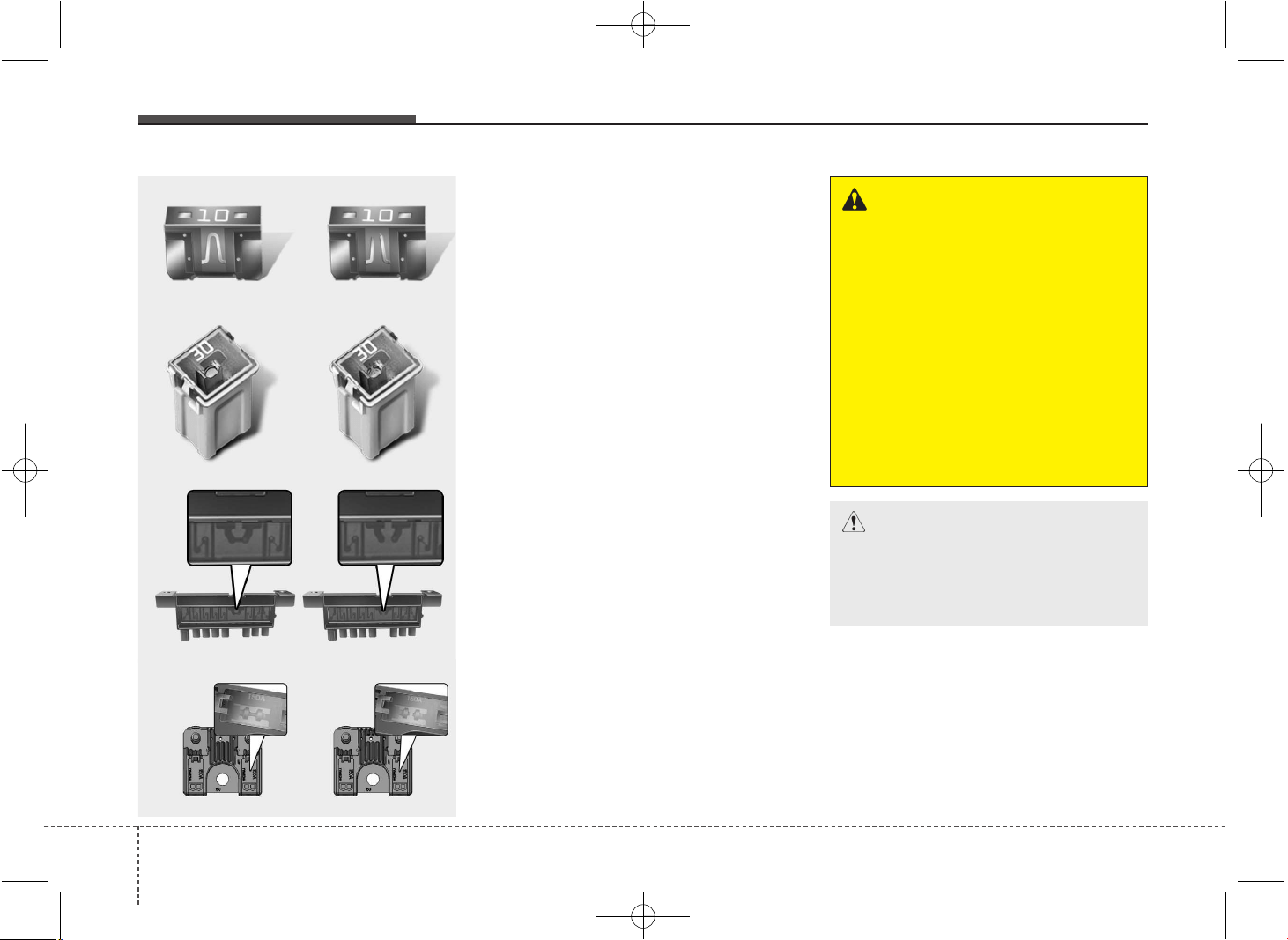
Maintenance
567
FUSES
A vehicle’s electrical system is protected
from electrical overload damage by
fuses.
This vehicle has 3 (or 4) fuse panels, one
located in the driver’s side panel bolster,
others in the engine compartment near
the battery.
If any of your vehicle’s lights, acces-
sories, or controls do not work, check the
appropriate circuit fuse. If a fuse has
blown, the element inside the fuse will be
melted.
If the electrical system does not work,
first check the driver’s side fuse panel.
Always replace a blown fuse with one of
the same rating.
Before replacing a blown fuse, move to
safe place, turn off the engine and all
electric devices, and disconnect the neg-
ative battery cable.
If the replacement fuse blows, this indi-
cates an electrical problem. Avoid using
the system involved and we recommend
that you consult an authorized Kia dealer.
Four kinds of fuses are used: blade type
for lower amperage rating, cartridge type,
battery fuse terminal and multi fuse type
for higher amperage ratings.
✽✽
NOTICE
The actual fuse/relay panel label may
differ from equipped items.
WARNING - Fuse
replacement
• Never replace a fuse with any-
thing but another fuse of the
same rating.
• A higher capacity fuse could
cause damage and possibly a fire.
• Never install a wire or aluminum
foil instead of the proper fuse -
even as a temporary repair. It may
cause extensive wiring damage
and a possible fire.
• Do not arbitrarily modify or add-
on electric wiring of the vehicle.
CAUTION
Do not use a screwdriver or any
other metal object to remove fuses
because it may cause a short circuit
and damage the system.
Normal
Normal
■ Blade type
■ Cartridge type
■ Multi fuse type
Blown
Blown
Normal Blown
ORB072110/ODM072020
Normal
Blown
■ Battery fuse terminal (BFT)
JD PE eng 7.QXP 03.01.2017 17:19 Page 56
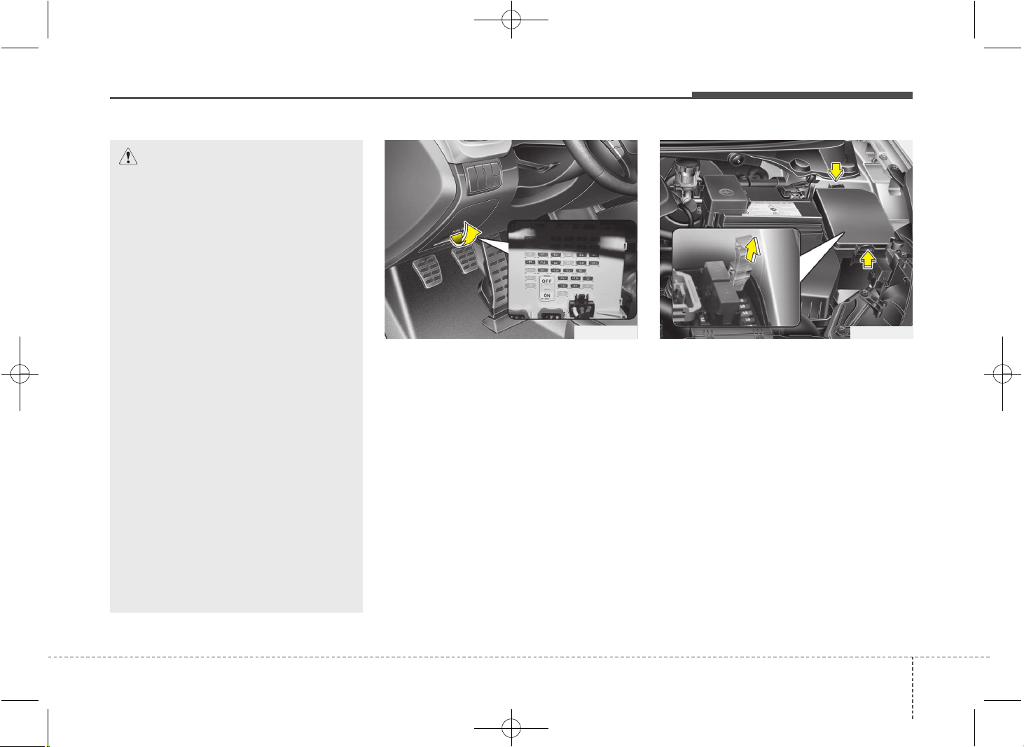
757
Maintenance
Inner panel fuse replacement
1. Turn the ignition switch and all other
switches off.
2. Open the fuse panel cover.
3. Pull the suspected fuse straight out.
Use the removal tool provided in the
engine compartment fuse panel.
4. Check the removed fuse; replace it if it
is blown.
5. Push in a new fuse of the same rating,
and make sure it fits tightly in the clips.
If it fits loosely, we recommend that you
consult an authorized Kia dealer.
If you do not have a spare, use a fuse of
the same rating from a circuit you may
not need for operating the vehicle, such
as the cigar lighter fuse.
If the headlights, fog lights, turn signal
lights, position lights or interior lights do
not work and there is nothing wrong with
the bulbs, we recommend that you con-
sult with an authorized Kia dealer.
OJD072016
OGD071017
CAUTION
• When replacing a blown fuse or
relay with a new one, make sure
the new fuse or relay fits tightly
into the clips. The incomplete fas-
tening fuse or relay may cause the
vehicle wiring and electric sys-
tems damage and a possible fire.
• Do not remove fuses, relays and
terminals fastened with bolts or
nuts. The fuses, relays and termi-
nals may be fastened incomplete-
ly, and it may cause a possible fire.
If fuses, relays and terminals fas-
tened with bolts or nuts are blown,
we recommend that you consult
with an authorized Kia dealer.
• Do not input any other objects
except fuses or relays into
fuse/relay terminals such as a driv-
er or wiring. It may cause contact
failure and system malfunction.
• Do not plug in screwdrivers or
aftermarket wiring into the terminal
originally designed for fuse and
relays only. The electrical system
and wiring of the vehicle interior
may be damaged or burned due to
contact failure.
JD PE eng 7.QXP 03.01.2017 17:19 Page 57
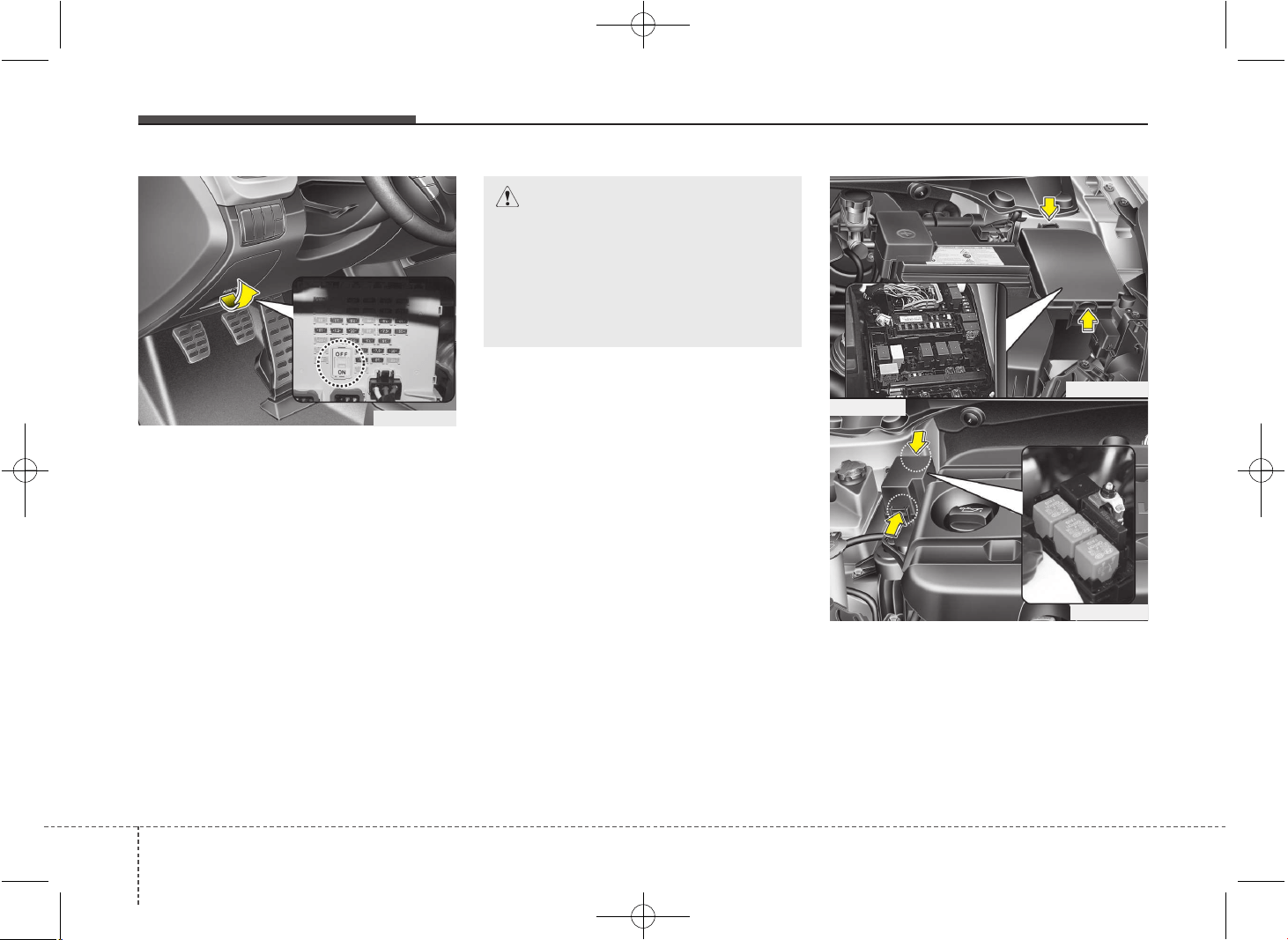
Maintenance
587
Fuse switch
Always, put the fuse switch at the ON
position.
If you move the switch to the OFF posi-
tion, some items such as audio and digi-
tal clock must be reset and transmitter
(or smart key) may not work properly.
When the fuse switch is in the OFF posi-
tion, a message "Turn on fuse switch" will
illuminate on the cluster.
✽✽
NOTICE
If you need to park your vehicle for pro-
longed periods more than 1 month,
move the fuse switch to the OFF position
to prevent the battery being discharged.
Engine compartment panel fuse
replacement
1. Turn the ignition switch and all other
switches off.
OGD071019
OGD071021
Diesel only
OJD072017
CAUTION
• Always place the fuse switch in
the ON position while driving the
vehicle.
• Do not move the fuse switch
repeatedly. The fuse switch may
be worn out.
JD PE eng 7.QXP 03.01.2017 17:19 Page 58
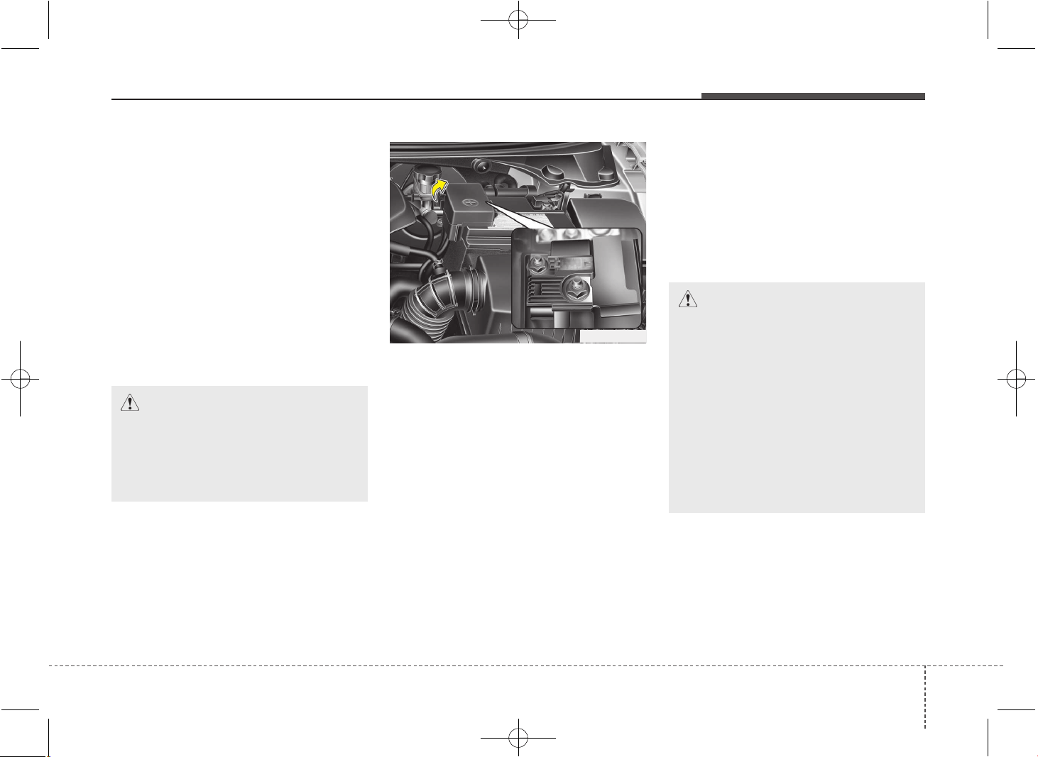
759
Maintenance
2. Remove the fuse box cover by press-
ing the tap and pulling up. When the
blade type fuse is disconnected,
remove it by using the clip designed for
changing fuses located in the engine
room fuse box. Upon removal, secure-
ly insert reserve fuse of equal quantity.
3. Check the removed fuse; replace it if it
is blown. To remove or insert the fuse,
use the fuse puller in the engine com-
partment fuse panel.
4. Push in a new fuse of the same rating,
and make sure it fits tightly in the clips.
If it fits loosely, we recommend that you
consult an authorized Kia dealer.
Main fuse
Electrical equipments are not working
even though inner panel and engine
compartment fuses are not blown, or
many of these are not working at the
same time, it may has blown the main
fuse(Battery Fuse Terminal type) inside
of the battery(+) cap.
If the main fuse is blown, it must be
removed as follows:
1. Turn off the engine.
2. Disconnect the negative battery cable.
3. Remove the nuts shown in the picture
above.
4. Replace the fuse with a new one of the
same rating.
5. Reinstall in the reverse order of
removal.
OGD071020
CAUTION
After checking the fuse box in the
engine compartment, install the
fuse box cover securely. If not,
water leaking may cause electrical
failures.
CAUTION
• After checking the main fuse,
install the cover securely when
you close the cover, check the
locking sound.
If not, electrical failures may
occur from water leaking in.
• Visually inspect the battery cap
for secure closing. If the battery
cap is not securely latched, the
electrical system may be dam-
aged to due influx of moisture
into the system.
JD PE eng 7.QXP 03.01.2017 17:19 Page 59
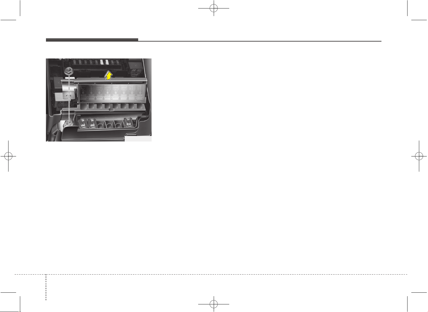
Maintenance
607
Multi fuse
If the multi fuse is blown, it must be
removed as follows:
1. Turn off the engine.
2. Disconnect the negative battery cable.
3. Remove the fuse panel on the right
side in the engine compartment.
4. Remove the nuts shown in the picture
above.
5. Replace the fuse with a new one of the
same rating.
6. Reinstall in the reverse order of
removal.
✽✽
NOTICE
If the multi fuse or main fuse is blown,
we recommend that you consult an
authorized Kia dealer.
OJD072018
JD PE eng 7.QXP 03.01.2017 17:19 Page 60
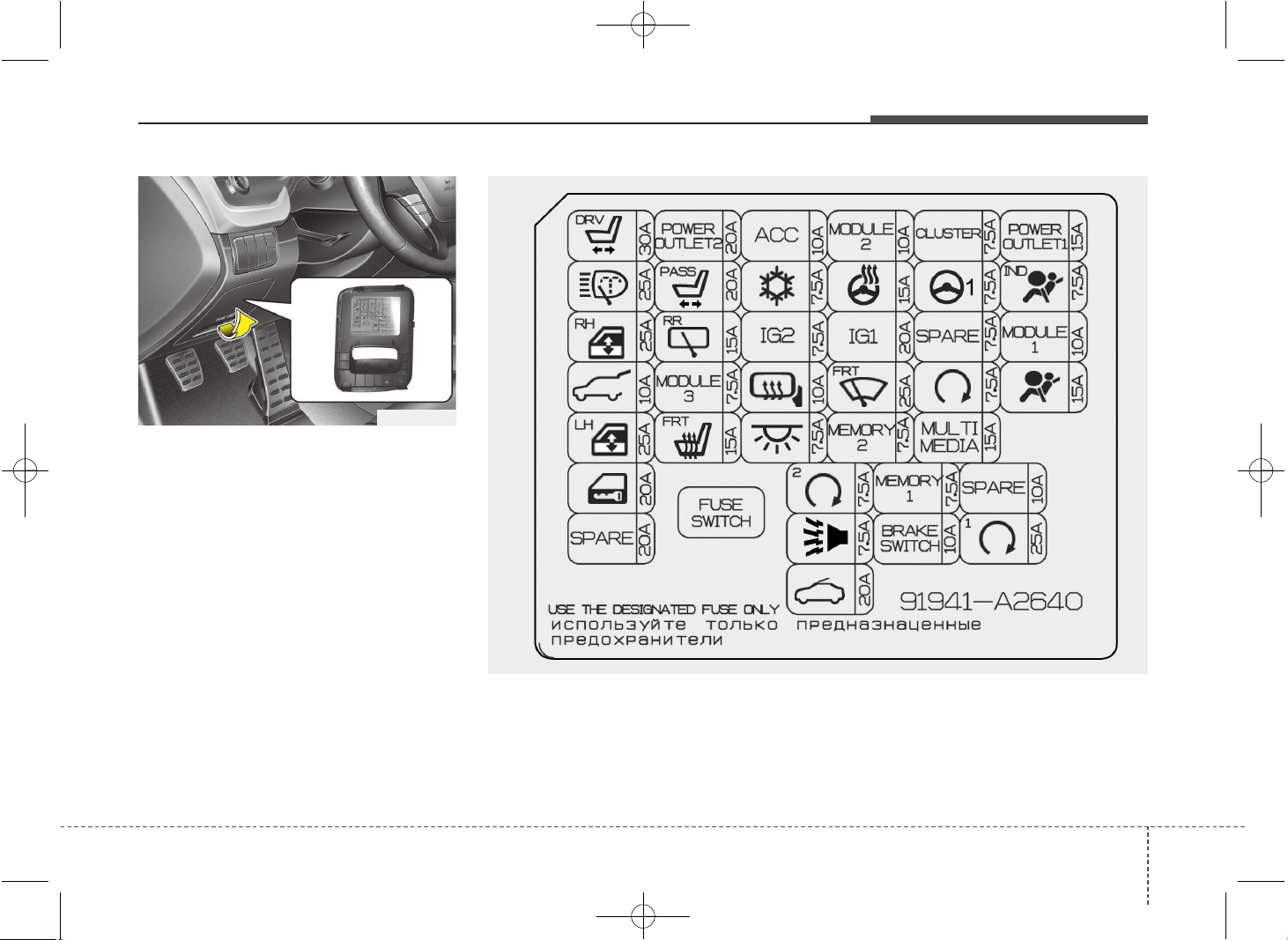
761
Maintenance
Fuse/relay panel description
Inner fuse panel
Inside the fuse/relay panel covers, you
can find the fuse/relay label describing
fuse/relay name and capacity.
✽✽
NOTICE
Not all fuse panel descriptions in this
manual may be applicable to your vehi-
cle. It is accurate at the time of printing.
When you inspect the fuse panel in your
vehicle, refer to the fuse panel label.
✽
✽
NOTICE
The actual fuse/relay panel label may
differ from equipped items.
OJD072019
OJD072020
JD PE eng 7.QXP 03.01.2017 17:19 Page 61
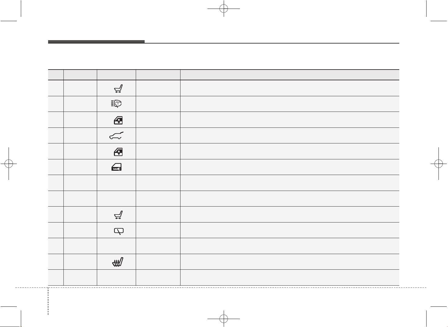
Maintenance
627
Instrument panel (Driver’s side fuse panel)
No. Fuse rating Symbol Fuse Name Protected component
1 30A
DRV
P/SEAT DRV
4WAY : Driver Lumbar Support Switch
6WAY : Driver Seat Manual Switch, Driver IMS Module
2 25A H/LP WASHER ICM Relay Box (Head Lamp Washer Relay)
3 25A
RH
P/WDW RH
Power Window Relay RH, Driver/Passenger Safety Power Window Module,
Rear Safety Power Window Module RH
4 10A T/GATE OPEN Tail Gate Relay
5 25A
LH
P/WDW LH
Power Window Relay LH, Driver/Passenger Safety Power
Window Module, Rear Safety Power Window Module LH
6 20A DR LOCK Door Lock/Unlock Relay, Dead Lock Relay
7 20A
SPAR
E
SPARE -
8 20A
POWER
OUTLET2
POWER
OUTLET 2
Cigarette Lighter, Rear Power Outlet
9 20A
PASS
P/SEAT ASS Passenger Lumbar Support Switch
10 15A
RR
RR WIPER ICM Relay Box (Rear Wiper Relay), Rear Wiper Motor
11 7.5A
MODULE
3
MODULE 3 Auto Light & Photo Sensor, AT lever (Shift Lock), Hazard Switch
12 15A
FRT
S/HEATER FRT Driver/Passenger Seat Warmer Module
13 10A
ACC
ACC
A/V & Navigation Head Unit (W/O ISG), Audio (W/O ISG), DC-DC Convertor (With ISG),
Digital Clock, Smart Key Control Module, BCM, Outside Mirror Switch, Outside Mirror
JD PE eng 7.QXP 03.01.2017 17:19 Page 62
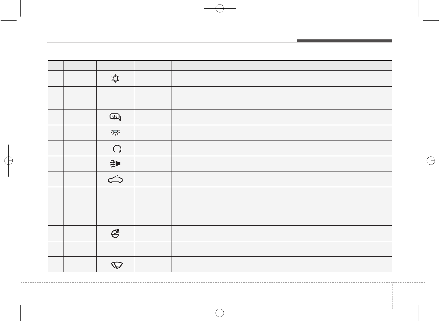
763
Maintenance
No. Fuse rating Symbol Fuse Name Protected component
14 7.5A A/CON Cluster Ionizer, A/C Control Module, Blower Relay, PTC Relay
15 7.5A
IG2
IG2
ICM Relay Box (Head Lamp Washer Relay), Rain Sensor, BCM, Electro Chromic Mirror,
Panorama Sunroof, Smart, Key Control Module, Passenger Seat Warmer Module,
Driver Seat Warmer Module
16 10A HTD MIRR Driver/Passenger Outside Mirror, ECU, A/C Control Module
17 7.5A
INTERIOR
LAMP
Glove Box Lamp, Luggage Lamp, Vanity Lamp LH/RH, Room Lamp,
Overhead Console Lamp
18 7.5A
2
PDM 2 Smart Key Control Module, Start/Stop Button Switch
19 7.5A B/HORN ICM Relay Box (Burglar Alarm Horn Relay)
20 20A SUNROOF Panorama Sunroof
21 10A
MODULE
2
MODULE 2
Electric Parking Brake Module, DC-DC Convertor (With ISG),
Head Lamp Leveling Device Switch, A/C Control Module, Rear Parking Assist Sensor,
Smart Parking Assist Control Module, Head Lamp LH/RH, ATM Shift Lever IND.,
Center Facia Switch, Crash Pad Lower Switch, Driver/Passenger Seat Warmer Module,
Driver IMS Module
22 15A HTD STRG Steering Wheel Heater
23 20A
IG1
IG1 E/R Fuse & Relay Box (ECU4, B/UP LAMP, ABS3, TCU2 FUSE)
24 25A
FRT
WIPER Wiper Relay , ICM Relay Box (Rain Sensor Relay), Front Wiper Motor
JD PE eng 7.QXP 03.01.2017 17:19 Page 63
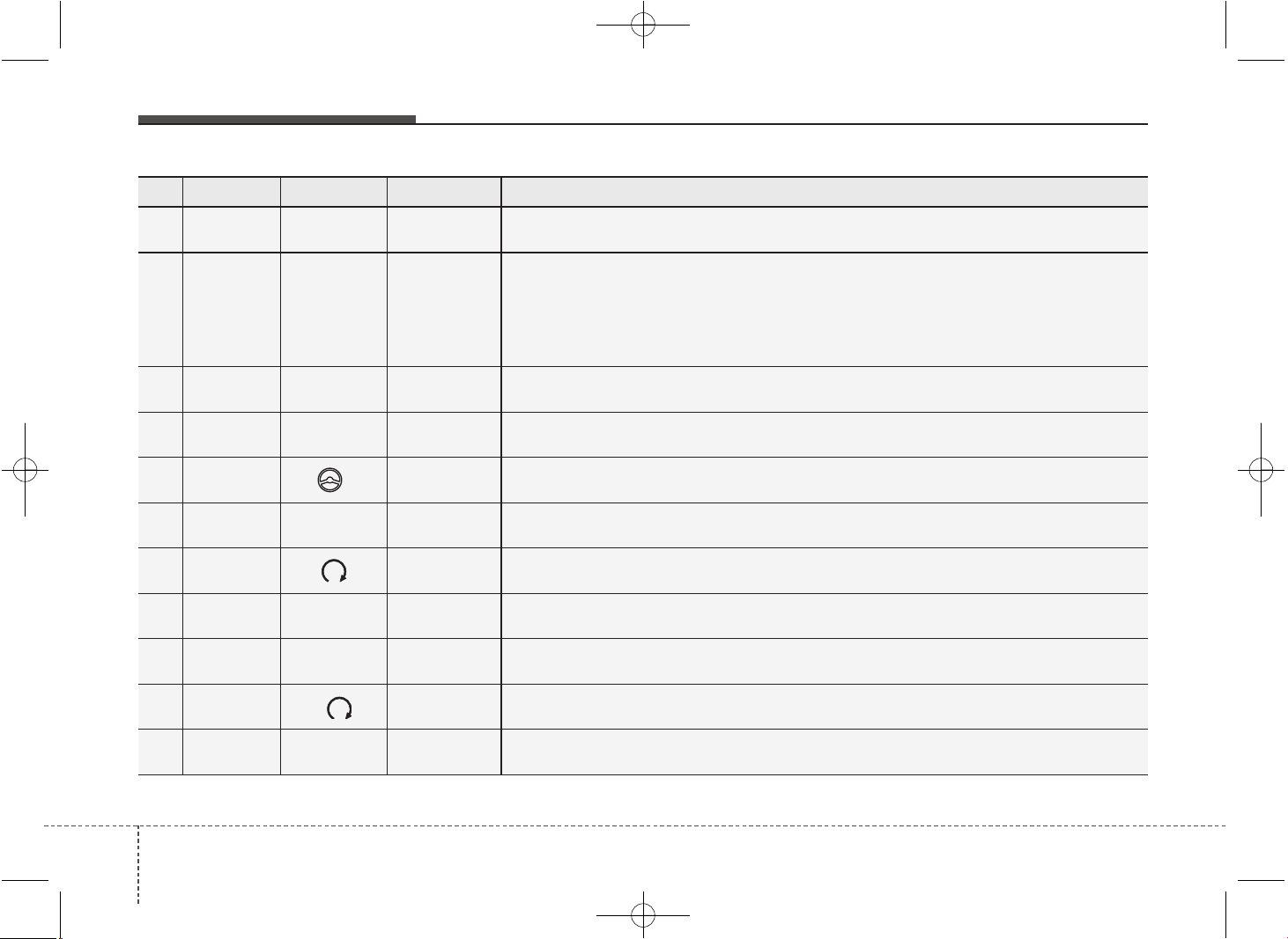
Maintenance
647
No. Fuse rating Symbol Fuse Name Protected component
25 7.5A
MEMOR
Y
2
MEMORY 2 Immobilizer Module (W/O Smart Key)
26 7.5A
MEMOR
Y
1
MEMORY 1
Driver/Passenger Outside Mirror (Folding), Driver/Passenger Smart Key Outside Handle,
Driver IMS Module, Center Facia Switch, Instrument Cluster, Tire Pressure Monitoring Module,
BCM, A/C Control Module, ICM Relay Box (Outside Mirror Folding/Unfolding Relay),
Ignition Key ILL. & Door Warning Switch, Rear Parking Assist Switch,
Data Link Connector, Buzzer
27 10A
BRAKE
SWITCH
BRAKE
SWITCH
Smart Key Control Module, Stop Lamp Switch
28 7.5A
CLUSTER
CLUSTER Instrument Cluster, Digital Clock
29 7.5A
1
POWER
STEERING
EPS Unit
30 7.5A
SPAR
E
SPARE -
31 7.5A START
Start Relay, ECU, Ignition Lock Switch, Transaxle Range Switch,
TCU, Smart Key Control Module
32 15A
MULTI
MEDIA
MULTI MEDIA
A/V & Navigation Head Unit (W/O ISG), Audio (W/O ISG),
DC-DC Convertor (With ISG), Digital Clock
33 10A
SPAR
E
SPARE -
34 25A
1
PDM 1 Smart Key Control Module
35 15A
POWER
OUTLET1
P/OUTLET 1 Front Power Outlet
JD PE eng 7.QXP 03.01.2017 17:20 Page 64
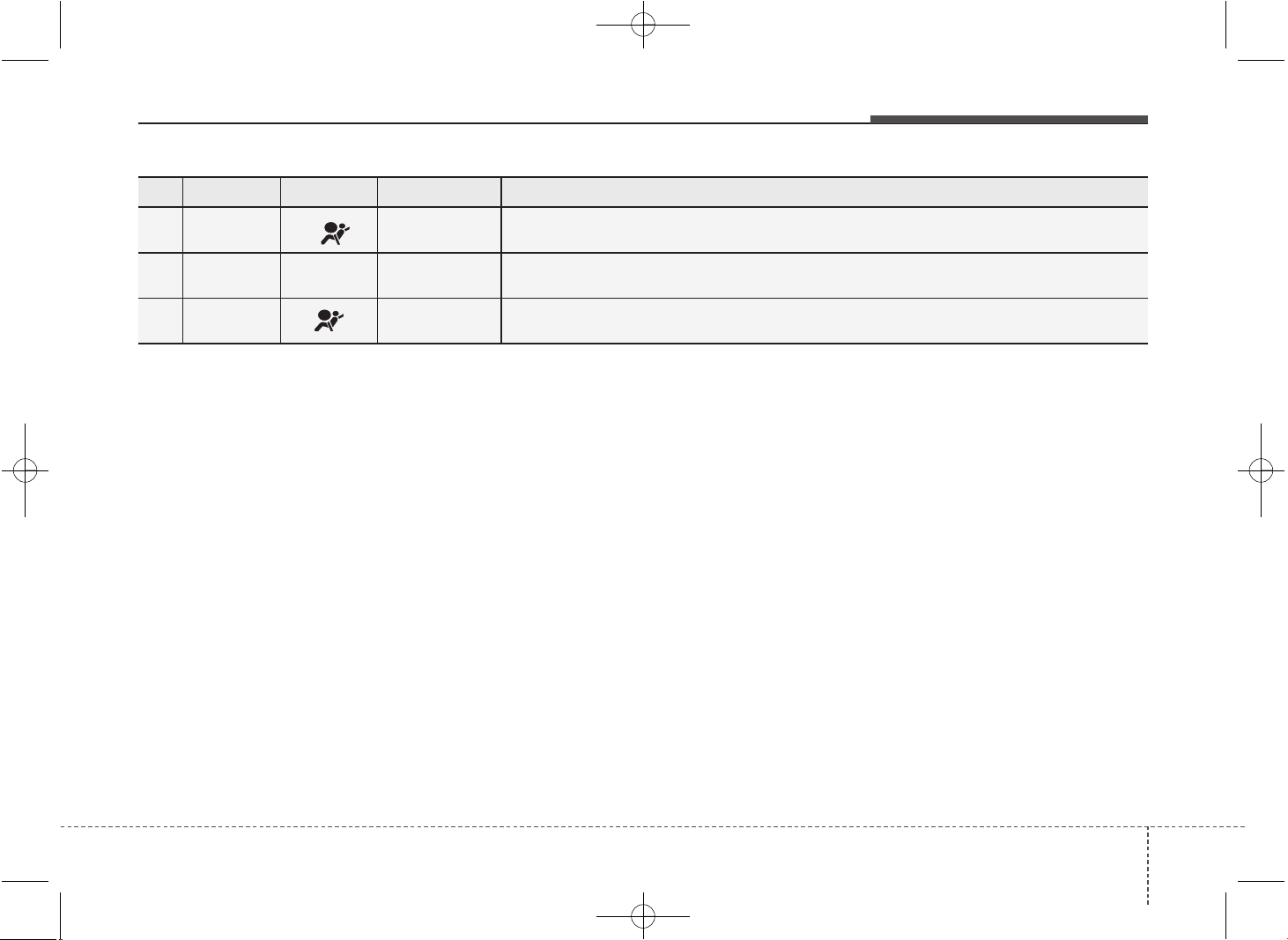
765
Maintenance
No. Fuse rating Symbol Fuse Name Protected component
36 7.5A
IND
A/BAG IND Instrument Cluster
37 10A
MODULE
1
MODULE 1
BCM, Tire Pressure Monitoring Module, AT Lever,
Audio, Adaptive Front Lighting Module, LDWS Unit
38 15A A/BAG SRS Control Module
JD PE eng 7.QXP 03.01.2017 17:20 Page 65
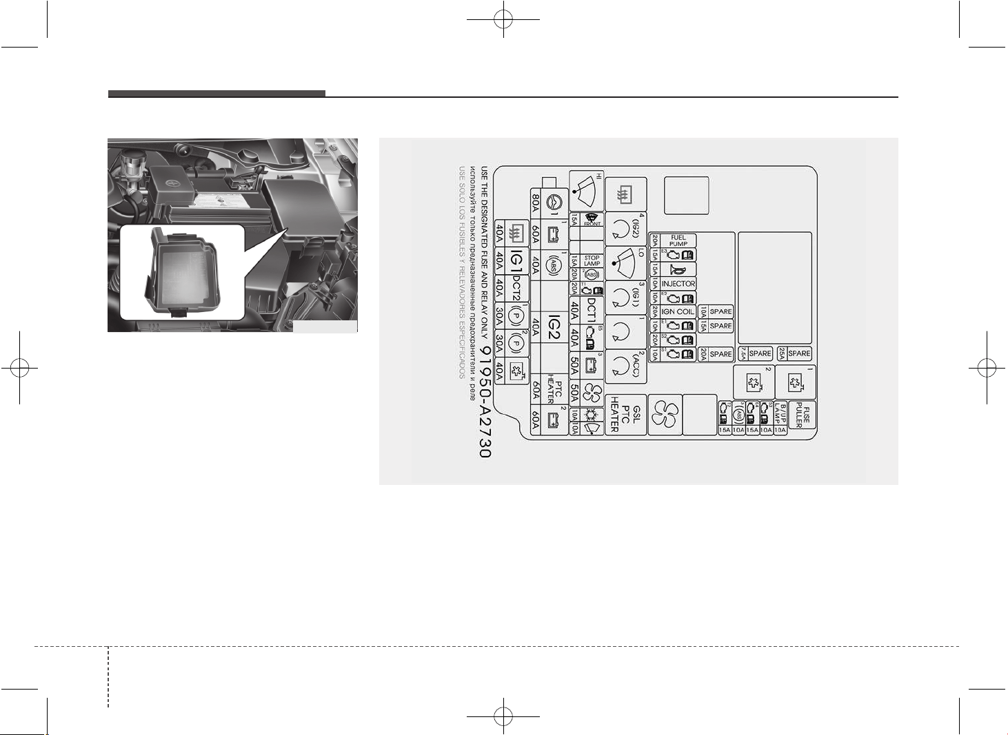
Maintenance
667
Engine compartment fuse panel
(for gasoline engine MPI, GDI)
✽✽
NOTICE
The actual fuse/relay panel label may
differ from equipped items.
OGD071023
OJD075105L
JD PE eng 7.QXP 03.01.2017 17:20 Page 66
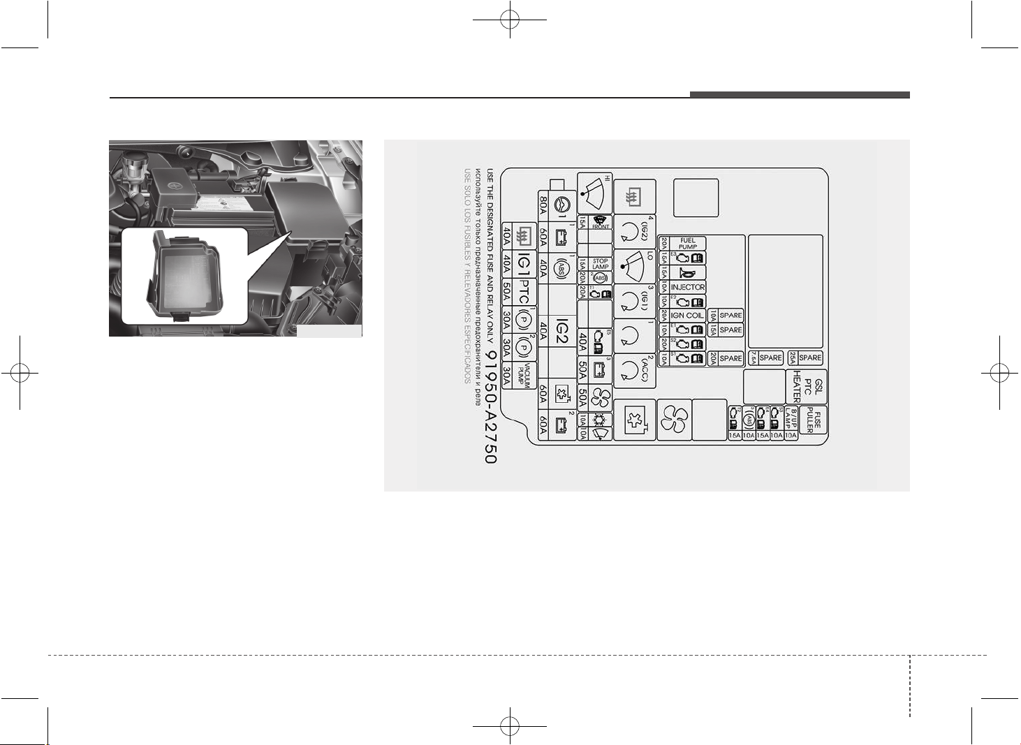
767
Maintenance
Engine compartment fuse panel
(for gasoline engine T-GDI)
✽✽
NOTICE
The actual fuse/relay panel label may
differ from equipped items.
OGD071023
OJD075104L
JD PE eng 7.QXP 03.01.2017 17:20 Page 67
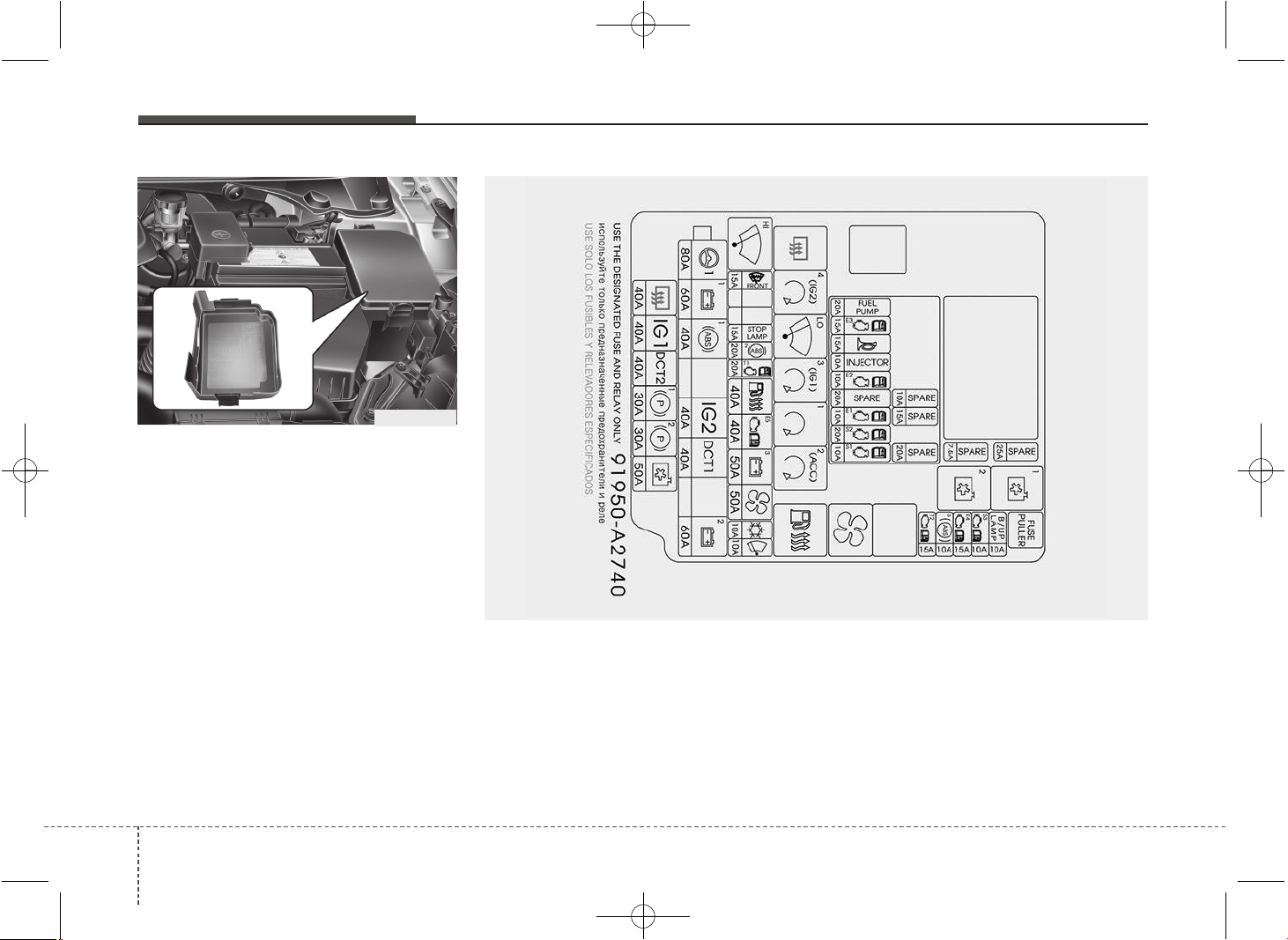
Maintenance
687
Engine compartment fuse panel
(for diesel engine)
✽✽
NOTICE
The actual fuse/relay panel label may
differ from equipped items.
OGD071023
OJD075103L
JD PE eng 7.QXP 03.01.2017 17:20 Page 68
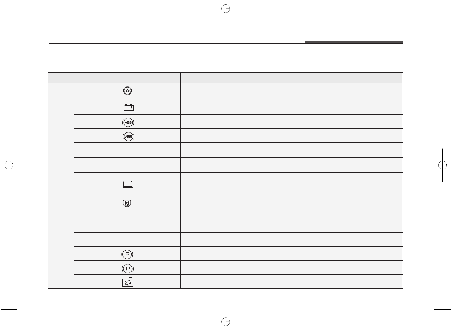
769
Maintenance
Fuse Fuse rating Symbol Fuse Name Protected component
MULTI
FUSE
80A
1
POWER
STEERING
EPS Unit
60A
B+1
B+1
Inner Fuse Panel, IPS1 (H/LAMP HI LH,H/LAMP LOW LH, FRT TURN LH,
POSITION LAMP LH), IPS2 (STATIC BENDING LAMP LH/RH, DRL LH/RH)
40A
1
ABS1 ESC Control Module, ABS Control Module
40A
2
ABS2 ESC Control Module, ABS Control Module, Multipurpose Check Connector
40A
IG2
IG2
W/O Smart Key : Ignition Switch, START RELAY
With Smart Key : IG2 RELAY, START RELAY
60A
PTC
HEATER
PTC
HEATER
PTC Relay (Gasoline)
60A
B+2
B+2
Inner Fuse Panel, IPS3 (H/LAMP HI RH,H/LAMP LOW RH, FRT TURN RH,POSITION
LAMP RH), IPS4 (FRT FOG LAMP LH/RH, REAR TURN LH/RH), IPS5 (REAR FOG LAMP,
INT TAIL LAMP)
FUSE
40A RR HTD RR HTD RELAY , RR HTD
40A
IG1
IG1
W/O Smart Key : Ignition Switch
With Smart Key : IG1 RELAY, ACC RELAY,
INNER FUSE PANEL (FUSE No. - 8/13/21/23/28/29/35/36/37/38)
40A
DCT2
DCT2 TCU (DCT)
30A
1
EPB1 Electric Parking Brake Module
30A
2
EPB2 Electric Parking Brake Module
40A C/FAN C/FAN LO RELAY, C/FAN HI RELAY
Engine compartment main fuse panel (for gasoline engine MPI, GDI)
JD PE eng 7.QXP 03.01.2017 17:20 Page 69
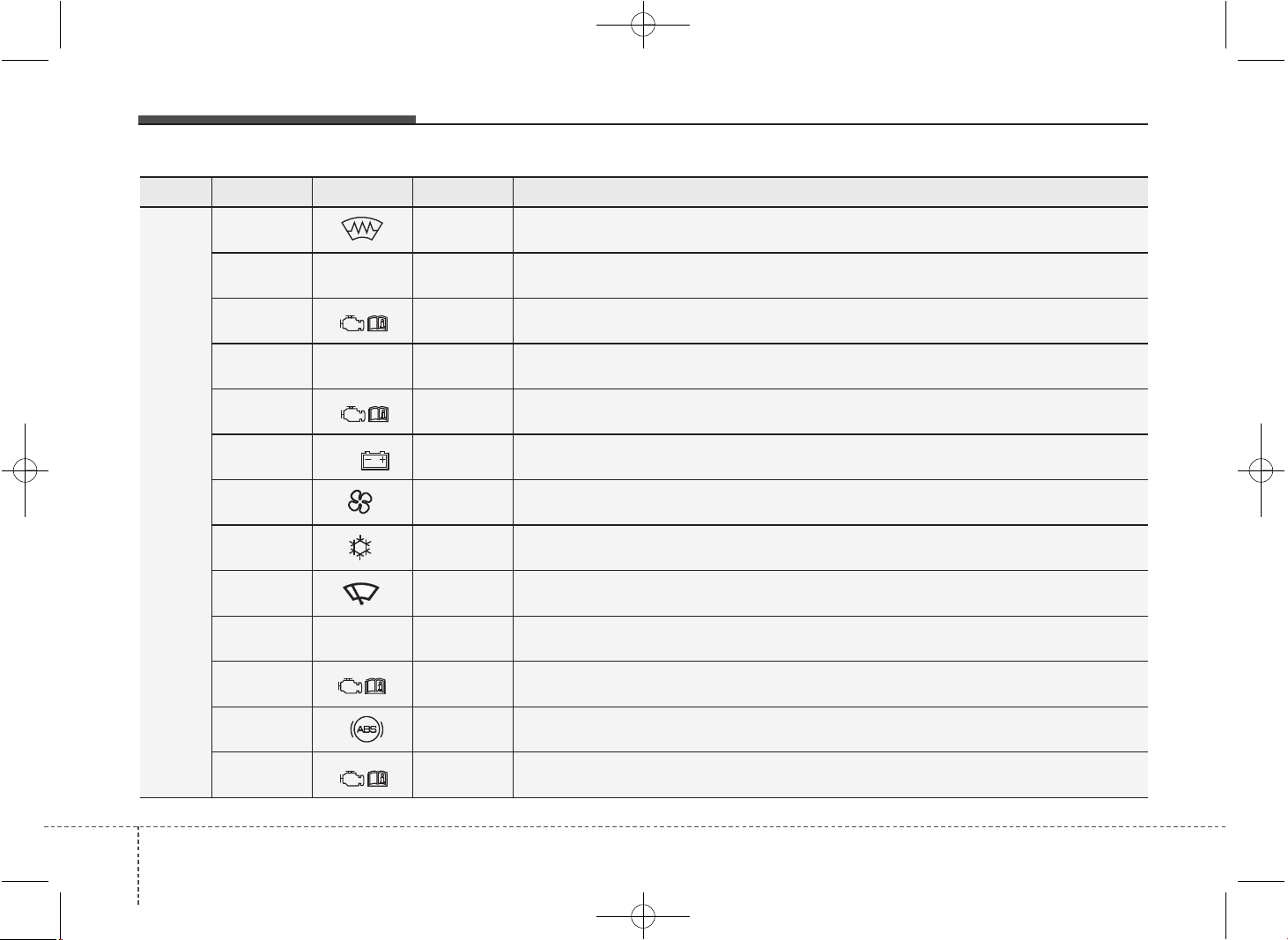
Maintenance
707
Fuse Fuse rating Symbol Fuse Name Protected component
FUSE
15A DEICER ICM Relay Box (Front Deicer Relay)
15A
STOP
LAMP
STOP LAMP Stop signal electronic module
20A
5
TCU1 TCU
40A
DCT1
DCT1 TCU (DCT)
40A
7
EMS EMS Box (FUSE No. - 1/2/3/4/5/6/7/8/9)
50A
B+3
B+3 Inner Fuse Panel (Leak Current Autocut Device, Fuse No. - 6/19/20/17/32/26/25)
50A BLOWER BLOWER RELAY
10A A/CON A/C Control Module
10A WIPER FRT ECU, Rain Sensor
10A
B/UP
LAMP
B/UP LP M/T : Back-up Lamp Switch, A/T : Transaxle Range Switch, TCU
15A
4
ECU4 Smart Key Control Module, Immobilizer Module, ECU
10A
3
ABS3 ESC Control Module, ABS Control Module, Yaw Rate Sensor, HAC, ESS RELAY
15A
6
TCU2 Transaxle Range Switch, TCU, Stop Lamp Switch
JD PE eng 7.QXP 03.01.2017 17:20 Page 70
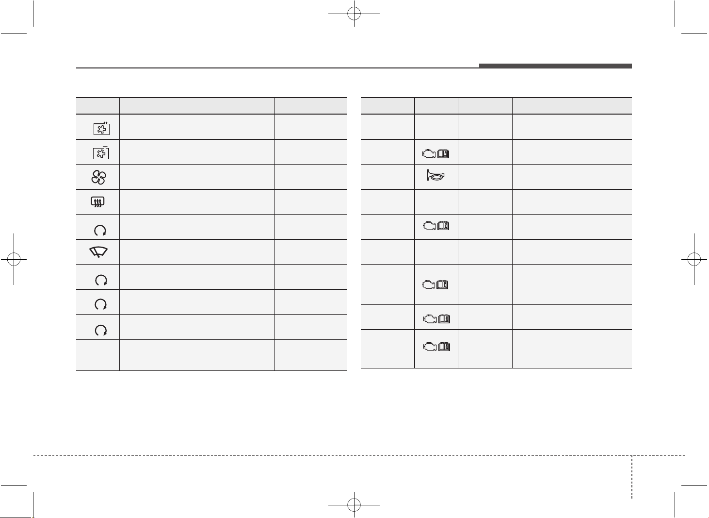
771
Maintenance
Symbol Relay Name Type
LO
COOLING FAN LOW RELAY PLUG MICRO
HI
COOLING FAN HIGH RELAY PLUG MICRO
BLOWER RELAY PLUG MICRO
REAR DEFOGGER RELAY PLUG MICRO
4 (IG2)
IG2 RELAY PLUG MICRO
FRT WIPER RELAY PLUG MICRO
3 (IG1)
IG1 RELAY PLUG MICRO
1
START RELAY PLUG MICRO
2 (ACC)
ACC RELAY PLUG MICRO
GSL
PTC
HEATER
PTC RELAY (GASOLINE) PLUG MINI
Fuse rating Symbol Fuse Name Relay Name
15A
F/PUMP
F/PUMP FUEL PUMP RELAY
15A
3
ECU3 ECU
15A HORN Horn Relay
10A
INJECTOR
INJECTOR
INJECTOR, ECU,
FUEL PUMP RELAY
10A
2
ECU2 ECU
20A
IGN
COIL
IGN COIL
Ignition Coil #1/#2/#3/#4,
Condenser
10A
9
SENSOR2
E/R Fuse & Relay Box
(COOLING LOW RELAY),
Oil Control Valve #1/#2
20A
1
ECU1 ECU
10A
8
SENSOR1
Oxygen Sensor (UP/DOWN),
Variable Intake Solenoid Valve,
Purge Control Solenoid Valve
JD PE eng 7.QXP 03.01.2017 17:20 Page 71
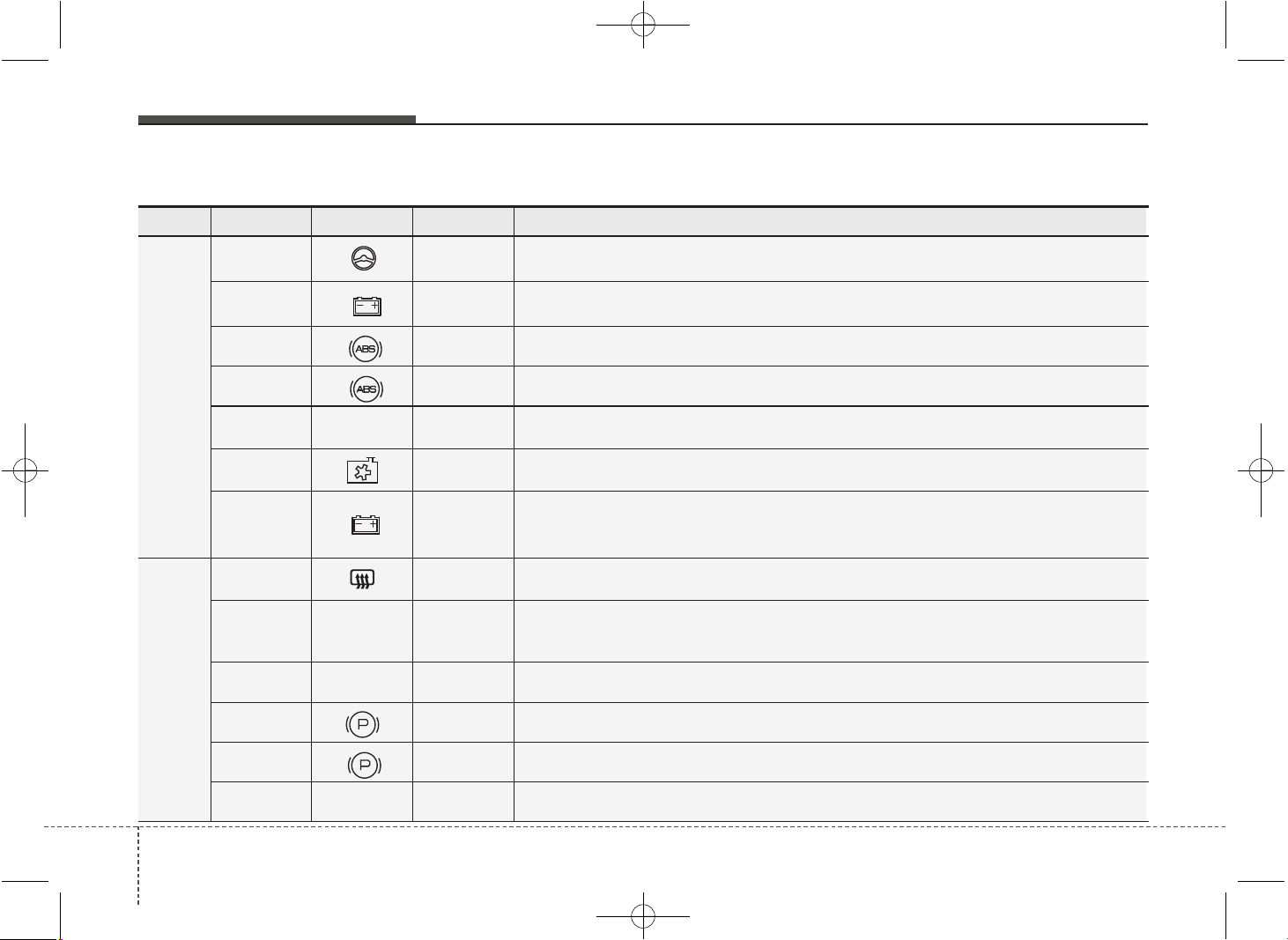
Maintenance
727
Fuse Fuse rating Symbol Fuse Name Protected component
MULTI
FUSE
80A
1
POWER
STEERING
EPS Unit
60A
B+1
B+1
Inner Fuse Panel, IPS1 (H/LAMP HI LH,H/LAMP LOW LH, FRT TURN LH,
POSITION LAMP LH), IPS2 (STATIC BENDING LAMP LH/RH, DRL LH/RH)
40A
1
ABS1 ESC Control Module, ABS Control Module
40A
2
ABS2 ESC Control Module, ABS Control Module, Multipurpose Check Connector
40A
IG2
IG2
W/O Smart Key : Ignition Switch, START RELAY
With Smart Key : IG2 RELAY, START RELAY
60A C/FAN C/FAN Relay
60A
B+2
B+2
Inner Fuse Panel, IPS3 (H/LAMP HI RH,H/LAMP LOW RH, FRT TURN RH,
POSITION LAMP RH), IPS4 (FRT FOG LAMP LH/RH, REAR TURN LH/RH),
IPS5 (REAR FOG LAMP, INT TAIL LAMP)
FUSE
40A RR HTD RR HTD RELAY , RR HTD
40A
IG1
IG1
W/O Smart Key : Ignition Switch
With Smart Key : IG1 RELAY, ACC RELAY,
INNER FUSE PANEL (FUSE No. - 8/13/21/23/28/29/35/36/37/38)
50A
PTC
HEATER
PTC
HEATER
PTC Relay (Gasoline)
30A
1
EPB1 Electric Parking Brake Module
30A
2
EPB2 Electric Parking Brake Module
30A
VACUUM
PUMP
VACUUM
PUMP
VACUUM PUMP
Engine compartment main fuse panel (for gasoline engine T-GDI)
JD PE eng 7.QXP 03.01.2017 17:20 Page 72
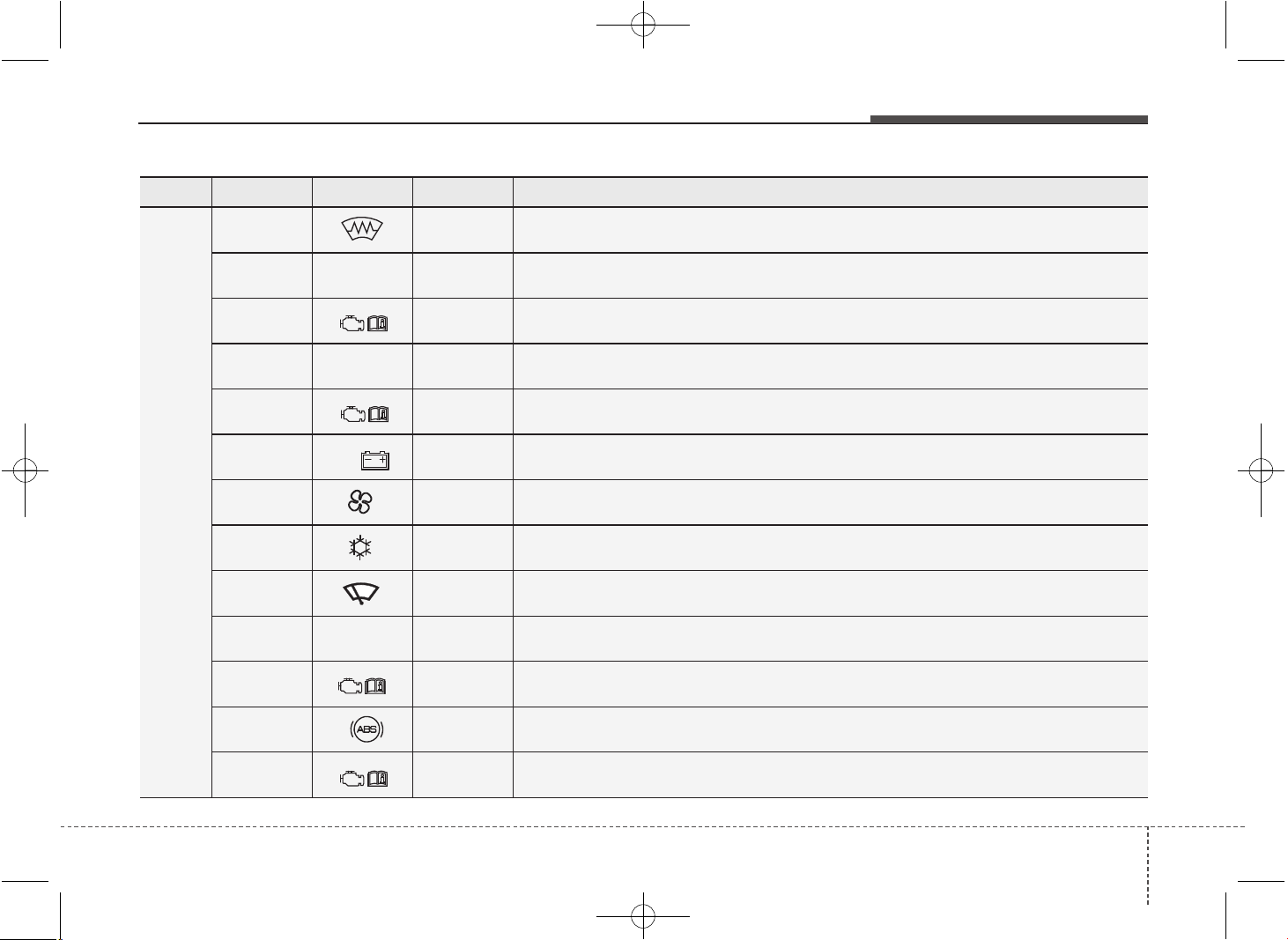
773
Maintenance
Fuse Fuse rating Symbol Fuse Name Protected component
FUSE
15A DEICER ICM Relay Box (Front Deicer Relay)
15A
STOP
LAMP
STOP LAMP Stop signal electronic module
20A
5
TCU1 TCU
40A
DCT1
DCT1 TCU (DCT)
40A
7
EMS EMS Box (FUSE No. - 1/2/3/4/5/6/7/8/9)
50A
B+3
B+3 Inner Fuse Panel (Leak Current Autocut Device, Fuse No. - 6/19/20/17/32/26/25)
50A BLOWER BLOWER RELAY
10A A/CON A/C Control Module
10A WIPER FRT ECU, Rain Sensor
10A
B/UP
LAMP
B/UP LP M/T : Back-up Lamp Switch, A/T : Transaxle Range Switch, TCU
15A
4
ECU4 Smart Key Control Module, Immobilizer Module, ECU
10A
3
ABS3 ESC Control Module, ABS Control Module, Yaw Rate Sensor, HAC, ESS RELAY
15A
6
TCU2 Transaxle Range Switch, TCU, Stop Lamp Switch
JD PE eng 7.QXP 03.01.2017 17:20 Page 73
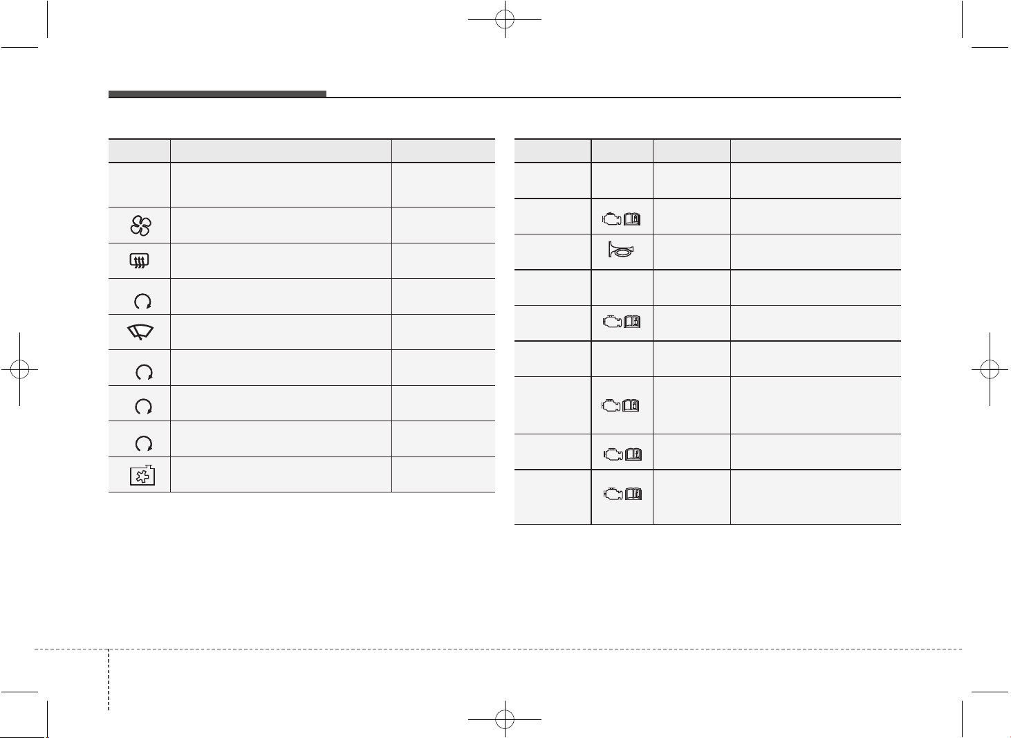
Maintenance
747
Symbol Relay Name Type
GSL
PTC
HEATER
PTC RELAY (GASOLINE) PLUG MICRO
BLOWER RELAY PLUG MICRO
REAR DEFOGGER RELAY PLUG MICRO
4 (IG2)
IG2 RELAY PLUG MICRO
FRT WIPER RELAY PLUG MICRO
3 (IG1)
IG1 RELAY PLUG MICRO
1
START RELAY PLUG MICRO
2 (ACC)
ACC RELAY PLUG MICRO
COOLING FAN PLUG MINI
Fuse rating Symbol Fuse Name Relay Name
15A
F/PUMP
F/PUMP FUEL PUMP RELAY
15A
3
ECU3 ECU
15A HORN Horn Relay
10A
INJECTOR
INJECTOR
INJECTOR, ECU,
FUEL PUMP RELAY
10A
2
ECU2 ECU
20A
IGN
COIL
IGN COIL
Ignition Coil #1/#2/#3/#4,
Condenser
10A
9
SENSOR2
E/R Fuse & Relay Box
(COOLING LOW RELAY),
Oil Control Valve #1/#2
20A
1
ECU1 ECU
10A
8
SENSOR1
Oxygen Sensor (UP/DOWN),
Variable Intake Solenoid Valve,
Purge Control Solenoid Valve
JD PE eng 7.QXP 03.01.2017 17:20 Page 74
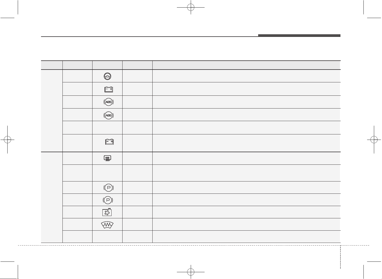
775
Maintenance
Fuse Fuse rating Symbol Fuse Name Protected component
MULTI
FUSE
80A
1
POWER
STEERING
EPS Unit
60A
B+1
B+1
Inner Fuse Panel, IPS1 (H/LAMP HI LH,H/LAMP LOW LH, FRT TURN LH, POSITION LAMP LH),
IPS2 (STATIC BENDING LAMP LH/RH, DRL LH/RH)
40A
1
ABS1 ESC Control Module, ABS Control Module
40A
2
ABS2 ESC Control Module, ABS Control Module, Multipurpose Check Connector
40A
IG2
IG2
W/O Smart Key : Ignition Switch, START RELAY
With Smart Key
: IG2 RELAY, START RELAY, INNER FUSE PANEL (
Fuse No. -
14/24/22/15/10)
60A
B+2
B+2
Inner Fuse Panel, IPS3 (H/LAMP HI RH,H/LAMP LOW RH, FRT TURN RH,
POSITION LAMP RH), IPS4 (FRT FOG LAMP LH/RH, REAR TURN LH/RH),
IPS5 (REAR FOG LAMP, INT TAIL LAMP)
FUSE
40A RR HTD RR HTD RELAY , RR HTD
40A
IG1
IG1
W/O Smart Key : Ignition Switch
With Smart Key : IG1 RELAY, ACC RELAY, INNER FUSE PANEL (Fuse No. - 38/36/21/37/
23/29/28, Fuse No. - 13/8/35)
30A
1
EPB1 Electric Parking Brake Module
30A
2
EPB2 Electric Parking Brake Module
50A C/FAN C/FAN LO RELAY, C/FAN HI RELAY
15A DEICER ICM Relay Box (Front Deicer Relay)
15A
STOP
LAMP
STOP LAMP Stop signal electronic module
Engine compartment main fuse panel (for diesel engine)
JD PE eng 7.QXP 03.01.2017 17:21 Page 75
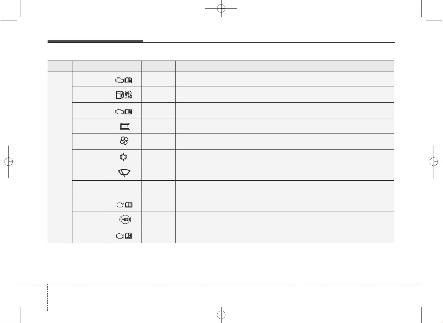
Maintenance
767
Fuse Fuse rating Symbol Fuse Name Protected component
FUSE
20A
5
TCU1 TCU
40A
FUEL
HEATER
FUEL HEATER RELAY
40A
7
EMS EMS BOX (Fuse No. - 1/2/3/4/5/6/7/8/9)
50A
B+3
B+3 Inner Fuse Panel (Leak Current Autocut Device, Fuse No. - 6/19/20/17/32/26/25)
50A BLOWER BLOWER RELAY
10A A/CON A/C Control Module
10A WIPER FRT ECU, Rain Sensor
10A
B/UP
LAMP
B/UP LP M/T : Back-up Lamp Switch, A/T : Transaxle Range Switch, TCU
15A
4
ECU4
Smart Key Control Module, Immobilizer Module, ECU, Air Flow Sensor,
Fuel Water Sensor
10A
3
ABS3 ESC Control Module, ABS Control Module, Yaw Rate Sensor
15A
6
TCU2 Transaxle Range Switch, TCU
JD PE eng 7.QXP 03.01.2017 17:21 Page 76
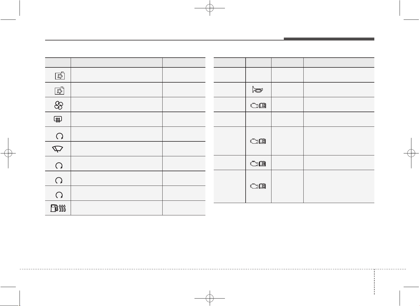
777
Maintenance
Symbol Relay Name Type
LO
COOLING FAN LOW RELAY PLUG MICRO
HI
COOLING FAN HIGH RELAY PLUG MICRO
BLOWER RELAY PLUG MICRO
REAR DEFOGGER RELAY PLUG MICRO
4 (IG2)
IG2 RELAY PLUG MICRO
FRT WIPER RELAY PLUG MICRO
3 (IG1)
IG1 RELAY PLUG MICRO
1
START RELAY PLUG MICRO
2 (ACC)
ACC RELAY PLUG MICRO
FUEL HEATER RELAY PLUG MINI
Fuse rating Symbol Fuse Name Relay Name
15A
SPARE
SPARE -
15A HORN HORN RELAY
10A
2
ECU2
Oil Level Sensor, Fuel
Pressure Control Valve
20A
SPARE
SPARE -
10A
9
SENSOR2
E/R Fuse & Relay Box
(COOLING FAN LOW RELAY),
Lambda Sensor (D4FB),
Stop Lamp Switch
20A
1
ECU1 ECU
10A
8
SENSOR1
DSL Box (PTC1 RELAY,
GLOW RELAY),
VGT Control Sensor,
Camshaft Position Sensor,
Electrical EGR Valve
JD PE eng 7.QXP 03.01.2017 17:21 Page 77
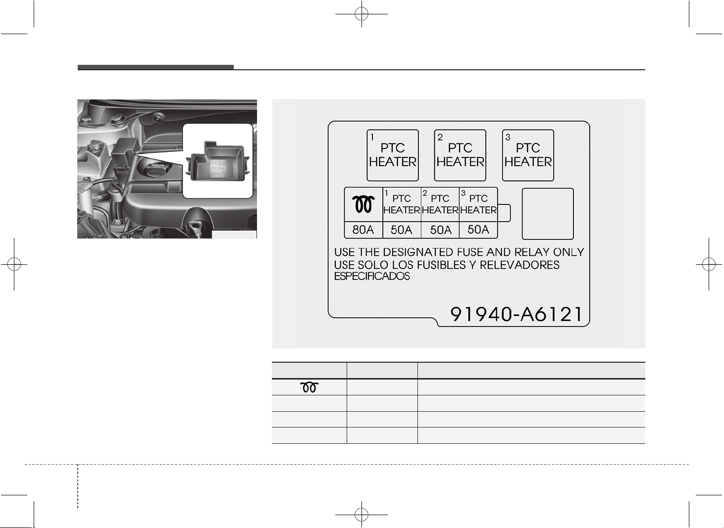
Maintenance
787
Engine compartment fuse panel
(Diesel engine only)
✽✽
NOTICE
The actual fuse/relay panel label may
differ from equipped items.
Description Fuse rating Protected Component
80A Glow Unit
PTC 1 50A PTC 1 Relay, PTC HEATER
PTC 2 50A PTC 2 Relay, PTC HEATER
PTC 3 50A PTC 3 Relay, PTC HEATER
OGD071024
OJD075102L
JD PE eng 7.QXP 03.01.2017 17:21 Page 78
779
Maintenance
LIGHT BULBS
Use only the bulbs of the specified
wattage.
✽✽
NOTICE
After driving in heavy rain or washing
the vehicle, headlight and taillight lenses
could appear foggy. This condition is
caused by the temperature difference
between the lamp inside and outside.
This is similar to the condensation on
your windows inside your vehicle during
rain and does not indicate a problem
with your vehicle. If the water leaks into
the lamp bulb circuitry, we recommend
that the system be checked by an
authorized Kia dealer.
WARNING - Working on
the lights
Prior to working on the light, firmly
apply the parking brake, ensure
that the ignition switch is turned to
the “LOCK” position (smart key:
turn off the engine) and turn off the
lights to avoid sudden movement
of the vehicle and burning your fin-
gers or getting an electric shock.
CAUTION
Be sure to replace the burned-out
bulb with one of the same wattage
rating. Otherwise, it may cause
damage to the fuse or electric
wiring system.
CAUTION
• If you do not have necessary
tools, the correct bulbs and the
expertise, we recommend that
you consult an authorized Kia
dealer. In many cases, it is diffi-
cult to replace vehicle light bulbs
because other parts of the vehicle
must be removed before you can
get to the bulb. This is especially
true if you have to remove the
headlight assembly to get to the
bulb(s).
Removing/installing the headlight
assembly can result in damage to
the vehicle.
• Do not install additional bulb or
LED. If you install that, the lamp
may not be operated properly and
fuse box or electric wiring system
may have problem.
JD PE eng 7.QXP 03.01.2017 17:21 Page 79
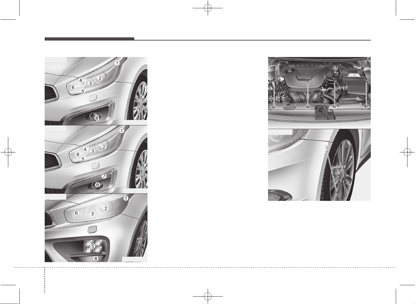
Maintenance
807
Front light replacement
(1) Front turn signal light
(2) Headlight (Low)
(3) Static bending light (if equipped)
(4) Position light
(5) Position light / Daytime running light
(DRL, LED Type) (if equipped)
(6) Headlight (High)
(7) Daytime running light (DRL, Bulb type)
(if equipped)
(8) Front fog light (if equipped)
1. Turn off the engine and open the hood.
2. Disconnect the negative battery cable.
3. Disconnect the power connector front
the back of the headlight assembly.
If you can reach the bulb without remov-
ing the headlight assembly, you do not
need to do step 4 to 7.
4. Loosen the retaining bolts on the front
bumper .
- Front bumper upper board : 4 EA
- Front bumper cover : 1 EA
OJD075052
OJD075066
■ Type A
■ Type B
OJD073081
■ Type C
OJD072053
OJD072054
Diesel only
JD PE eng 7.QXP 03.01.2017 17:21 Page 80
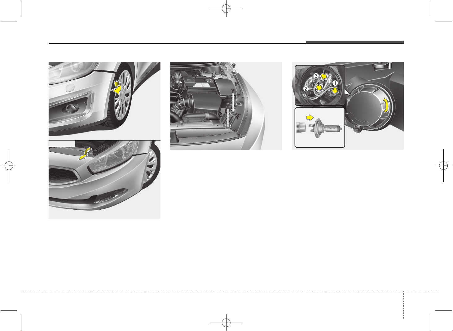
781
Maintenance
5. Pull out the front bumper cover.
6. Loosen the retaining bolt .
7. Pull out the headlight assembly from
the body of the vehicle.
Headlight (High, 1) and static bending
light (2, if equipped)
Follow the steps 1 to 7 from the previous
chapter.
8. Remove the cover by turning it coun-
terclockwise.
9. Disconnect the headlight bulb socket-
connector.
10. Unsnap the headlight bulb retaining
wire by depressing the end and push-
ing it upward.
11. Remove the bulb from the headlight
assembly.
12. Install a new headlight bulb and snap
the headlight bulb retaining wire into
position by aligning the wire with the
groove on the bulb.
OJD072041OJD072056
OJD075055
OJD075062
Diesel only
JD PE eng 7.QXP 03.01.2017 17:22 Page 81
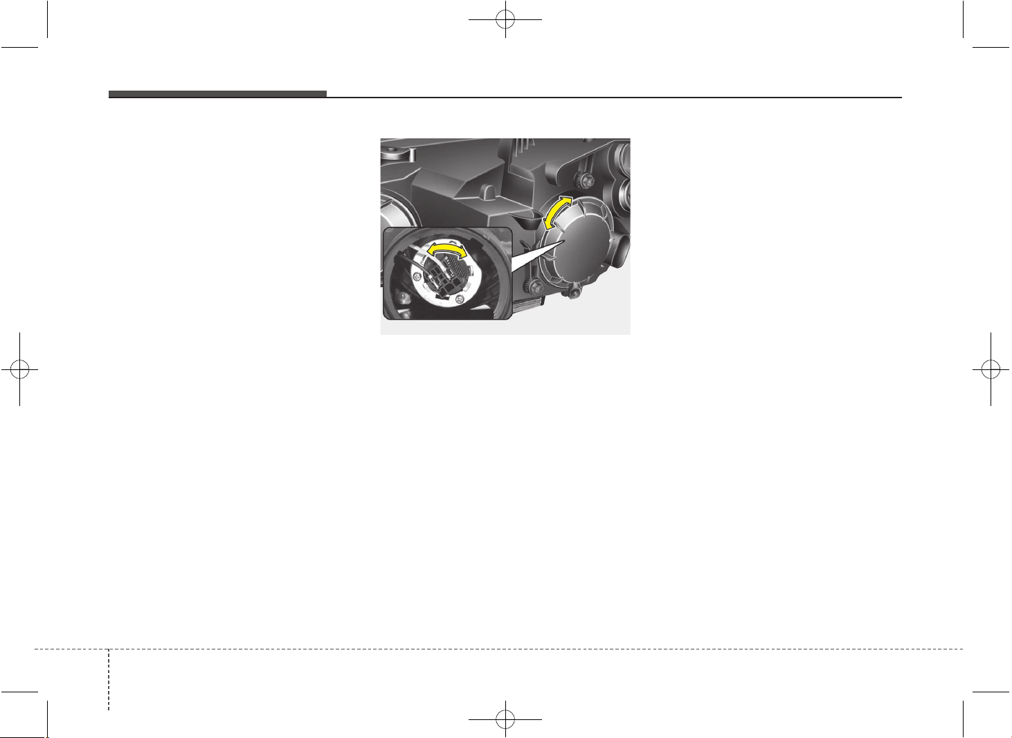
Maintenance
827
13. Connect the headlight bulb socket
connector.
14. Install the headlight bulb cover by
turning it clockwise.
15. Connect the power connector to the
back of the headlight assembly.
Position light (3, bulb type)
Follow the steps 1 to 9 from the previous
page.
10. Pull out the socket from the assembly.
11. Pull the bulb out of the socket.
12. Insert a new bulb into the socket.
13. Install the socket into the assembly.
14. Install the headlight bulb cover by
turning it clockwise.
Headlight (Low, Non-HID Type)
Follow the steps 1 to 7 from the previous
page.
8. Remove the cover by turning it coun-
terclockwise.
9. Remove the socket from the assembly
by turning the socket counterclockwise
until the tabs on the socket align with
the slots on the assembly.
10. Pull the bulb out of the socket.
11. Insert a new bulb into the socket.
12. Install the socket in the assembly by
aligning the tabs on the socket with
the slots in the assembly. Push the
socket into the assembly and turn the
socket clockwise.
13. Install the headlight bulb cover by
turning it clockwise.
✽✽
NOTICE
We recommend that the headlight aim-
ing be adjusted after an accident or
after the headlight assembly is rein-
stalled at an authorized Kia dealer.
OJD072042
JD PE eng 7.QXP 03.01.2017 17:22 Page 82
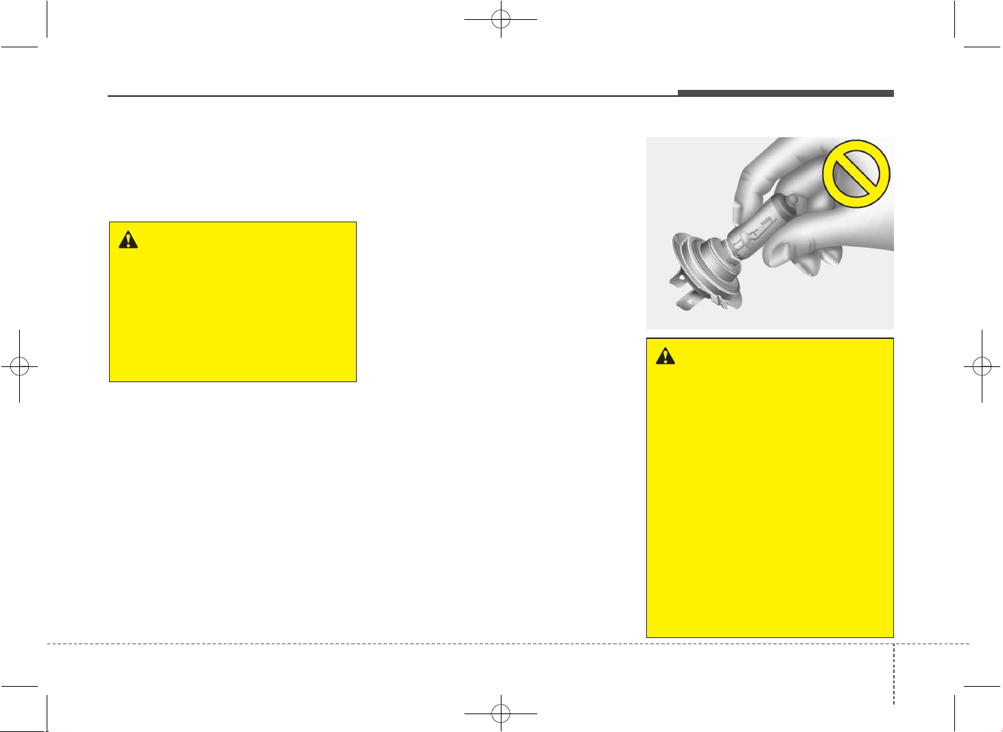
783
Maintenance
Headlight (Low, HID type),
Position light/DRL (LED type)
If the light does not operate, we recom-
mend that the system be checked by an
authorized Kia dealer.
✽✽
NOTICE
HID lamps have superior performance
vs. halogen bulbs. HID lamps are esti-
mated by the manufacturer to last twice
as long or longer than halogen bulbs
depending on their frequency of use.
They will probably require replacement
at some point in the life of the vehicle.
Cycling the headlamps on and off more
than typical use will shorten HID lamps
life. HID lamps do not fail in the same
manner as halogen incandescent lamps.
If a headlamp goes out after a period of
operation but will immediately relight
when the headlamp switch is cycled it is
likely the HID lamp needs to be replaced.
HID lighting components are more com-
plex than conventional halogen bulbs
thus have higher replacement cost.
❈❈
Traffic Change (For Europe)
The low beam light distribution is asym-
metric. If you go abroad to a country with
opposite traffic direction, this asymmetric
part will dazzle oncoming car driver. To
prevent dazzle, ECE regulation demand
several technical solutions (ex. automatic
change system, adhesive sheet, down
aiming). This headlamps are designed
not to dazzle opposite drivers. So, you
need not change your headlamps in a
country with opposite traffic direction.
WARNING - HID Headlight
low beam (if equipped)
Do not attempt to replace or
inspect the low beam (XENON bulb)
due to electric shock danger. If the
low beam (XENON bulb) is not
working, we recommend that the
system be checked by an author-
ized Kia dealer.
OHD076046
WARNING -
Halogen bulbs
• Halogen bulbs contain pressurized
gas that will produce flying pieces
of glass if broken.
• Always handle them carefully, and
avoid scratches and abrasions. If
the bulbs are lit, avoid contact with
liquids. Never touch the glass with
bare hands. Residual oil may cause
the bulb to overheat and burst
when lit. A bulb should be operated
only when installed in a headlight.
• If a bulb is damaged or cracked,
replace it immediately and carefully
dispose of it.
• Wear eye protection when chang-
ing a bulb. Allow the bulb to cool
down before handling it.
JD PE eng 7.QXP 03.01.2017 17:22 Page 83
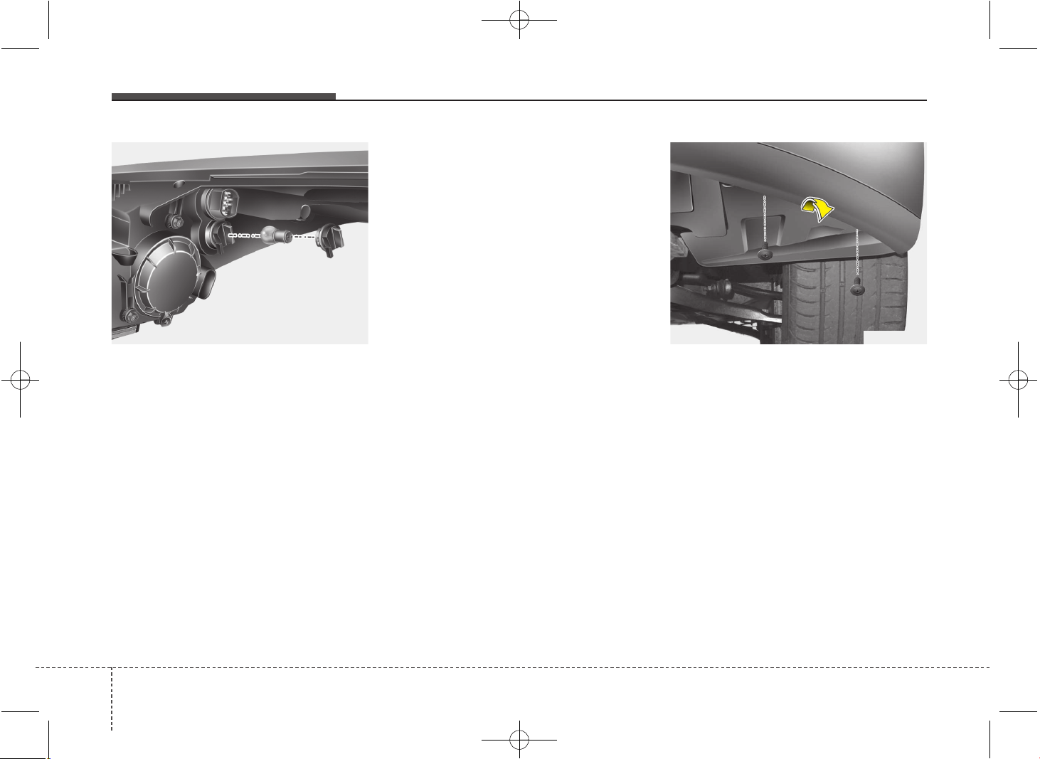
Maintenance
847
Turn signal light
Follow the steps 1 to 7 from the previous
page.
8. Remove the socket from the assembly
by turning the socket counterclockwise
until the tabs on the socket align with
the slots on the assembly.
9. Remove the bulb from the socket by
pressing it in and rotating it counter-
clockwise until the tabs on the bulb
align with the slots in the socket. Pull
the bulb out of the socket.
10. Insert a new bulb by inserting it into
the socket and rotating it until it locks
into place.
11. Install the socket in the assembly by
aligning the tabs on the socket with
the slots in the assembly. Push the
socket into the assembly and turn the
socket clockwise.
Front fog light, Daytime running light
(if equipped)
1. Pull the wheel guard down by rotating
the screws.
2. Reach your hand into the back of the
front bumper.
3. Disconnect the power connector from
the socket.
OJD072044 OJD072050
JD PE eng 7.QXP 03.01.2017 17:22 Page 84
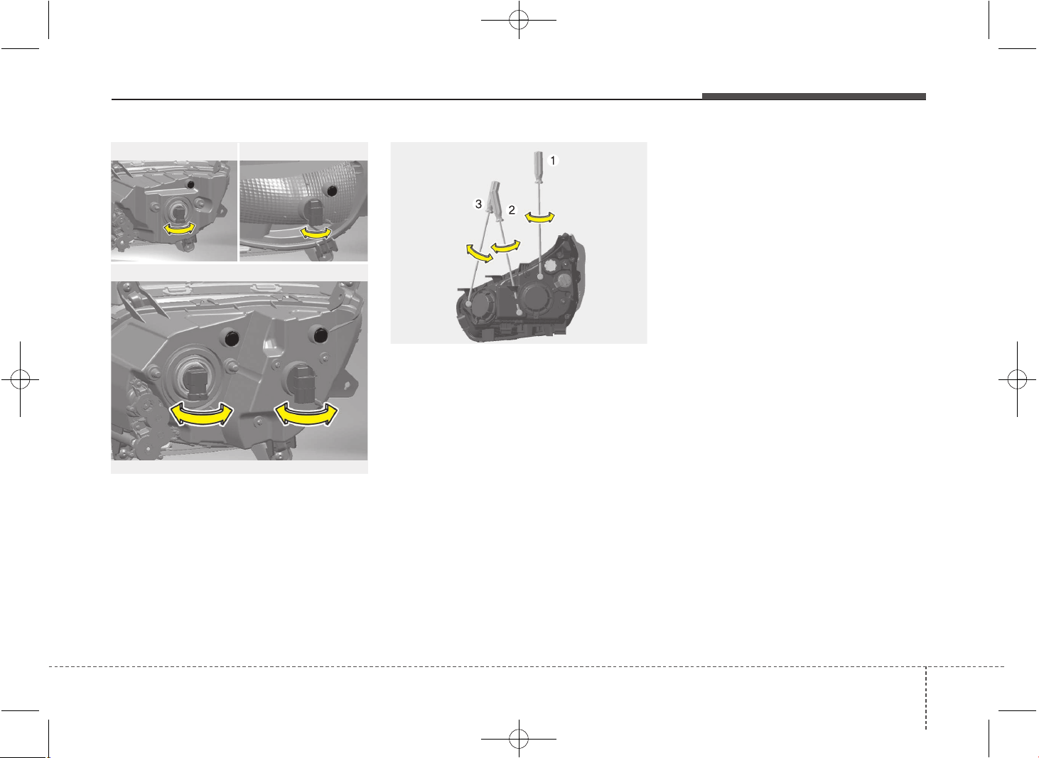
785
Maintenance
4. Remove the bulb-socket from the
housing by turning the socket counter
clockwise until the tabs on the socket
align with the slots on the housing.
5. Install the new bulb-socket into the
housing by aligning the tabs on the
socket with the slots in the housing.
Push the socket into the housing and
turn the socket clockwise.
6. Connect the power connector to the
socket.
Headlight and front fog light aim-
ing (for Europe)
Headlight aiming
Without AFLS
1. Inflate the tires to the specified pres-
sure and remove any loads from the
vehicle except the driver, spare tire,
and tools.
2. The vehicle should be placed on a flat
floor.
3. Draw vertical lines (Vertical lines pass-
ing through respective head lamp cen-
ters) and a horizontal line (Horizontal
line passing through center of head
lamps) on the screen.
4. With the head lamp and battery in nor-
mal condition, aim the head lamps so
the brightest portion falls on the hori-
zontal and vertical lines.
5. To aim the low beam left or right, turn
the driver (1) clockwise or counter-
clockwise. To aim the low beam up or
down, turn the driver (2) clockwise or
counterclockwise.
To aim the high beam up or down, turn
the driver (3) clockwise or counter-
clockwise.
OJD072027
■ Fog light
■ Fog light+DRL (Bulb type)
■ DRL
OJD073067/OJD073068/OJD073069
JD PE eng 7.QXP 03.01.2017 17:22 Page 85
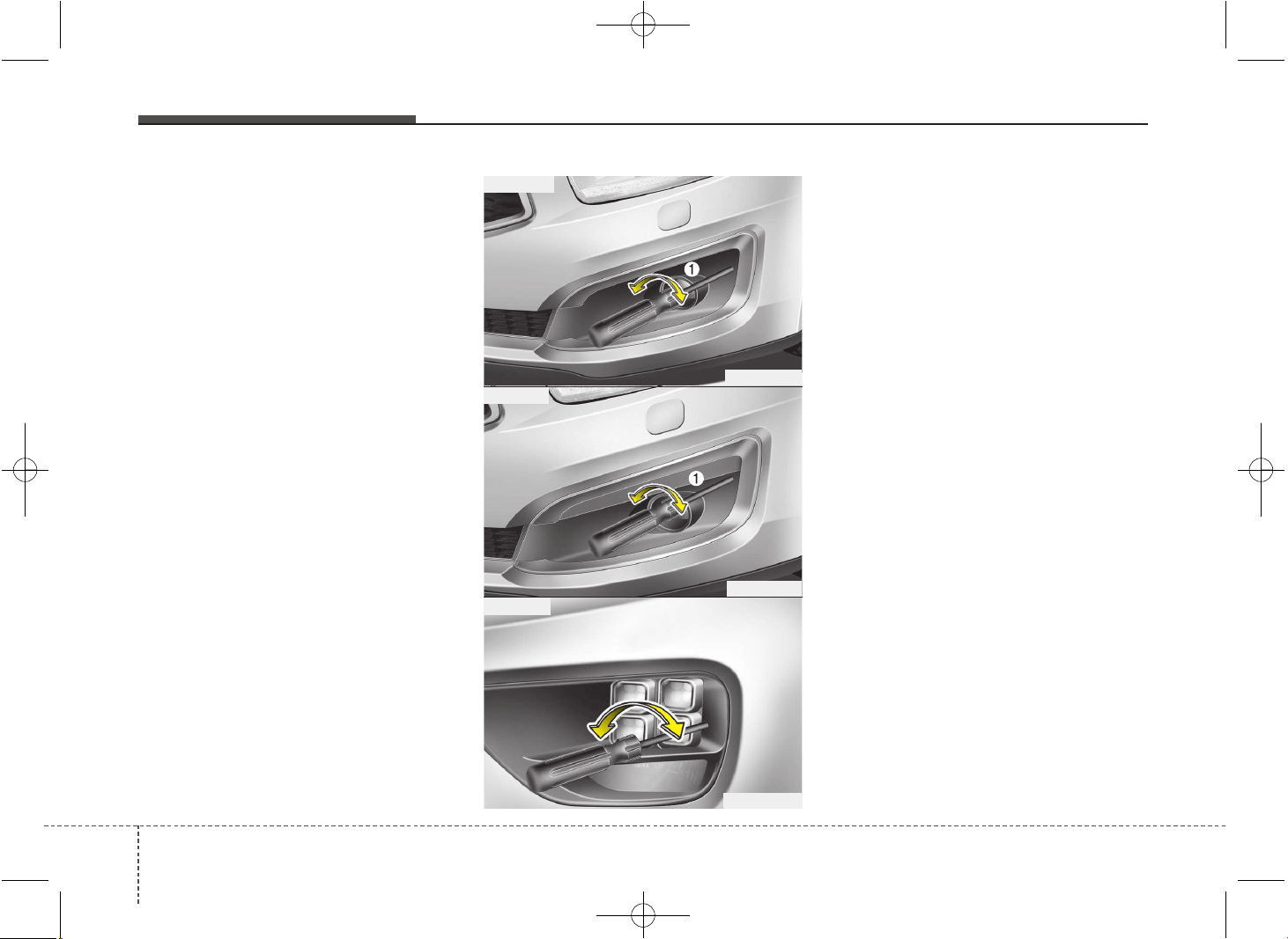
Maintenance
867
With AFLS
1. Turn off the engine
2. Turn the light switch to the low beam
position.
3. Position the tires straight ahead with
the steering wheel.
4. Turn on the engine.
5. Inflate the tires to the specified pres-
sure and remove any loads from the
vehicle except the driver, spare tire,
and tools.
6. The vehicle should be placed on a flat
floor.
7. Draw vertical lines (Vertical lines pass-
ing through respective head lamp cen-
ters) and a horizontal line (Horizontal
line passing through center of head
lamps) on the screen.
8. With the head lamp and battery in nor-
mal condition, aim the head lamps so
the brightest portion falls on the hori-
zontal and vertical lines.
9. To aim the low beam left or right, turn
the driver (1) clockwise or counter-
clockwise. To aim the low beam up or
down, turn the driver (2) clockwise or
counterclockwise. To aim the high
beam up or down, turn the driver (3)
clockwise or counterclockwise.
Front fog light aiming
The front fog lamp can be aimed as the
same manner of the head lamps aiming.
With the front fog lamps and battery nor-
mal condition, aim the front fog lamps. To
aim the front fog lamp up or down, turn the
driver (1) clockwise or counterclockwise.
OJD075028
OJD075070
OJD073082
■ Type A
■ Type B
■ Type C
JD PE eng 7.QXP 03.01.2017 17:22 Page 86
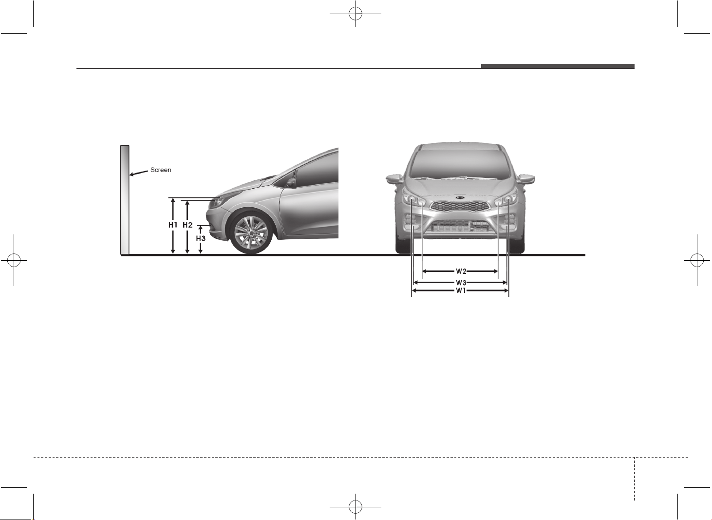
787
Maintenance
Aiming point
OJD075051
< Ground Height >
< Distance between lamps >
H1 : Height between the head lamp bulb center and ground (Low beam)
H2 : Height between the head lamp bulb center and ground (High beam)
H3 : Height between the fog lamp bulb center and ground
W1 : Distance between the two head lamp bulbs centers (Low beam)
W2 : Distance between the two head lamp bulbs centers (High beam)
W3 : Distance between the two fog lamp bulbs centers
JD PE eng 7.QXP 03.01.2017 17:22 Page 87
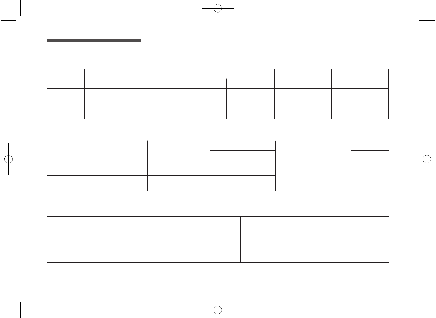
Maintenance
887
Vehicle
condition
H1 H2
H3
W1 W2
W3
FOG ONLY
FOG+DRL FOG ONLY FOG+DRL
Without
driver
689/699/684
(27.1)/(27.5)/(26.9)
646/656/641
(25.4)/(25.8)/(25.2)
345/355/340
(13.6)/(13.9)/(13.4)
328/338/323
(12.9)/(13.3)/(12.7)
1,300
(51.2)
1,049
(41.3)
1,346
(52.9)
1,334
(52.5)
With driver
680/690/675
(26.7)/(27.2)/(26.6)
637/647/632
(25.1)/(25.5)/(24.9)
336/346/331
(13.2)/(13.6)/(13.0)
319/329/314
(12.6)/(12.9)/(12.4)
■ 3,5 Door and Wagon
■ 3 and 5Door (for T-GDI)
Vehicle
condition
H1 H2 H3 W1 W2 W3
Without
driver
689/699/684
(27.1)/(27.5)/(26.9)
646/656/641
(25.4)/(25.8)/(25.2)
305/315/300
(12.0)/(12.4)/(11.8)
1,300
(51.2)
1,049
(41.3)
1,332
(52.4)
With driver
680/690/675
(26.7)/(27.2)/(26.6)
637/647/632
(25.1)/(25.5)/(24.9)
296/306/291
(11.7)/(12.0)/(11.5)
■ 3,5 Door and Wagon (for Sports Pack)
Unit: mm (in)
Vehicle
condition
H1
H2
H3
W1 W2
W3
FOG ONLY FOG ONLY
Without
driver
689/699/684
(27.1)/(27.5)/(26.9)
646/656/641
(25.4)/(25.8)/(25.2)
308/318/303
(12.1)/(12.5)/(11.9)
1,300
(51.2)
1,049
(41.3)
1,308
(51.5)
With driver
680/690/675
(26.7)/(27.2)/(26.6)
637/647/632
(25.1)/(25.5)/(24.9)
299/309/294
(11.8)/(12.2)/(11.6)
JD PE eng 7.QXP 03.01.2017 17:23 Page 88
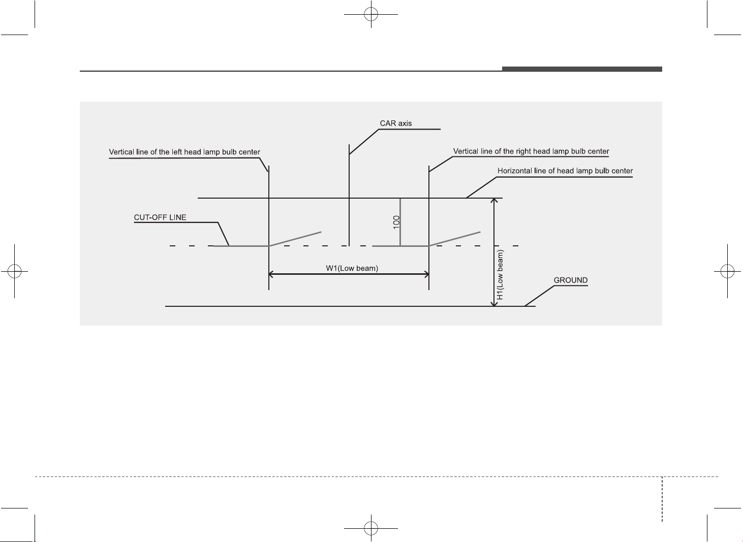
789
Maintenance
OMD051054L
Head lamp low beam (driver’s side)
1. Turn the low beam on without driver aboard.
2. The cut-off line should be projected in the cut-off line shown in the picture.
3. When aiming the low beam, vertical aiming should be adjusted after adjusting the horizontal aiming.
4. If head lamp leveling device is equipped, adjust the head lamp leveling device switch with 0 positions.
■ Based on 10m screen
JD PE eng 7.QXP 03.01.2017 17:23 Page 89
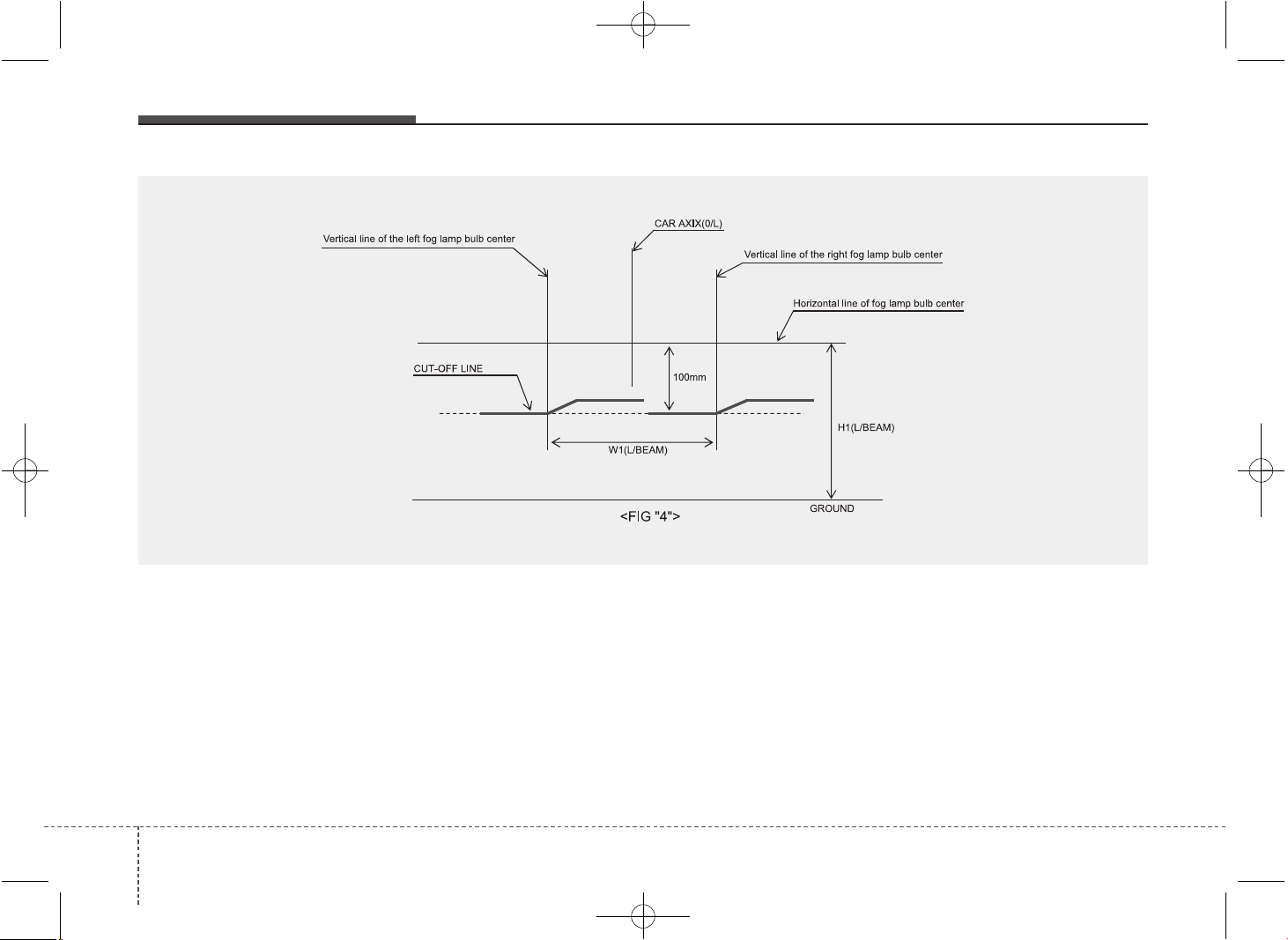
Maintenance
907
OXM073102
Head lamp low beam (LHD)
1. Turn the low beam on without driver aboard.
2. The cut-off line should be projected in the cut-off line shown in the picture.
3. When aiming the low beam, vertical aiming should be adjusted after adjusting the horizontal aiming.
4. If head lamp leveling device is equipped, adjust the head lamp leveling device switch with 0 positions.
■ Based on 10m screen
JD PE eng 7.QXP 03.01.2017 17:23 Page 90
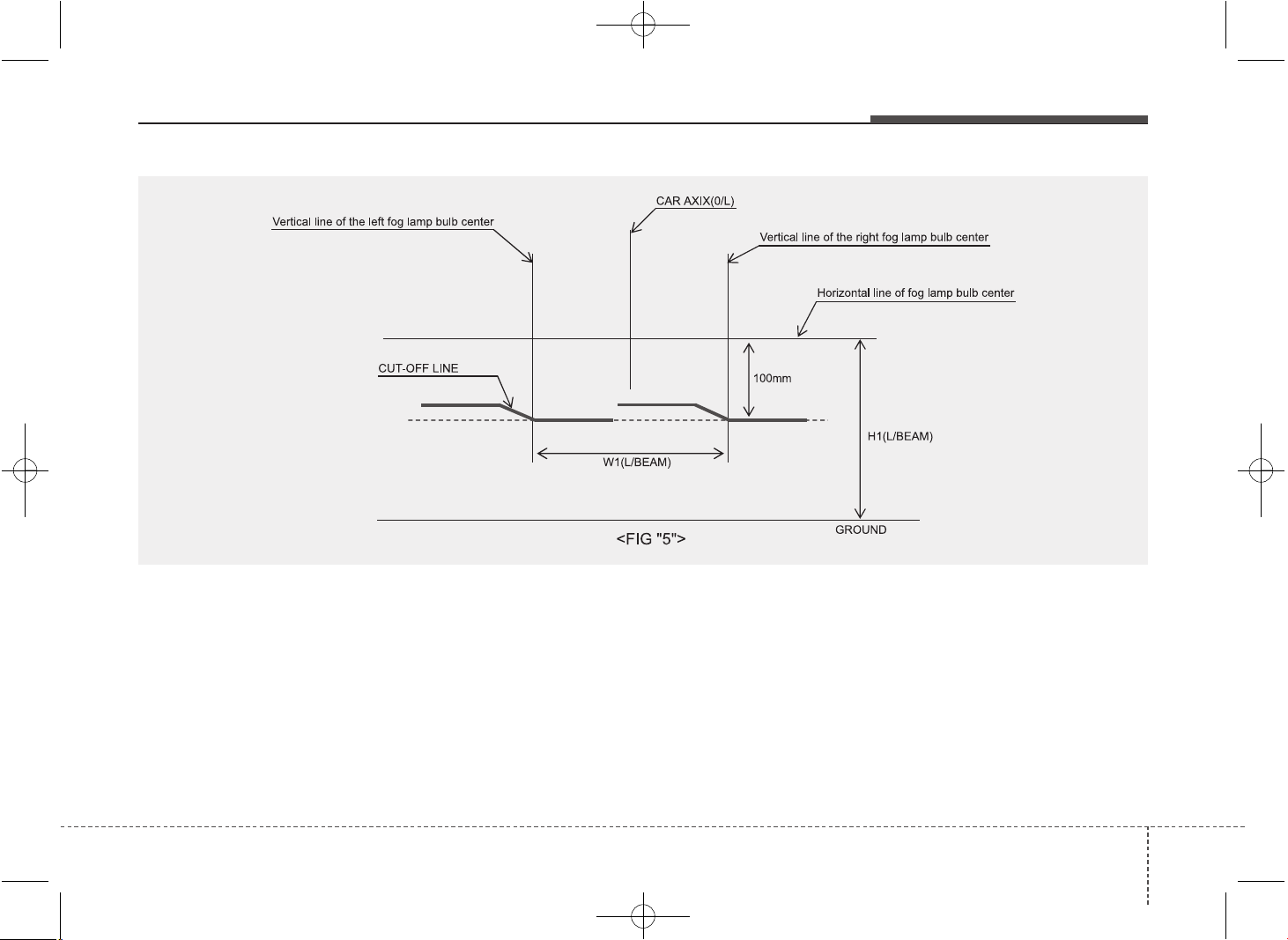
791
Maintenance
OXM073103
Head lamp low beam (RHD)
1. Turn the low beam on without driver aboard.
2. The cut-off line should be projected in the cut-off line shown in the picture.
3. When aiming the low beam, vertical aiming should be adjusted after adjusting the horizontal aiming.
4. If head lamp leveling device is equipped, adjust the head lamp leveling device switch with 0 positions.
JD PE eng 7.QXP 03.01.2017 17:23 Page 91
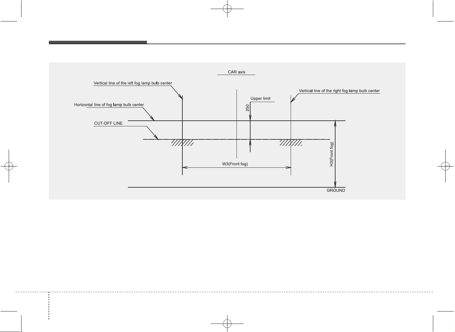
Maintenance
927
OGDE071056-JD
Front fog light
1. Turn the front fog lamp on without the driver aboard.
2. The cut-off line should be projected in the allowable range (shaded region).
■ Based on 10m screen
JD PE eng 7.QXP 03.01.2017 17:23 Page 92
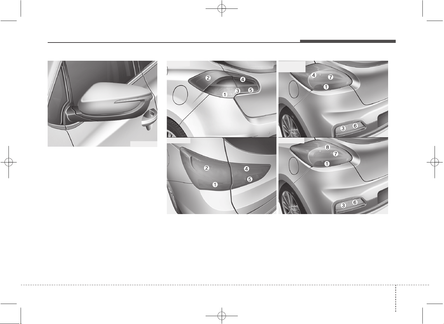
793
Maintenance
Side repeater light bulb replace-
ment
If the light bulb does not operate, we rec-
ommend that the system be checked by
an authorized Kia dealer.
(1) Rear turn signal light
(2) Stop/tail light
(3) Back-up light
(for 3 Door and 5 Door)
(4) Tail light or stop/tail light
(for LED type)
(5) Rear fog light (for 5 Door), Rear fog
light (Driver’s side) or back-up light
(Passenger’s side), (for wagon)
(6) Rear fog light (for 3 Door)
(7) Stop light (for 3 Door)
(8) Tail light (for 3 Door)
OJD072029
Rear combination light bulb replacement
■ 5 Door
■ Wagon
■ 3 Door
• Type A
• Type B
OJD075030/OJD075063/OJD073072/OJD073072
JD PE eng 7.QXP 03.01.2017 17:23 Page 93
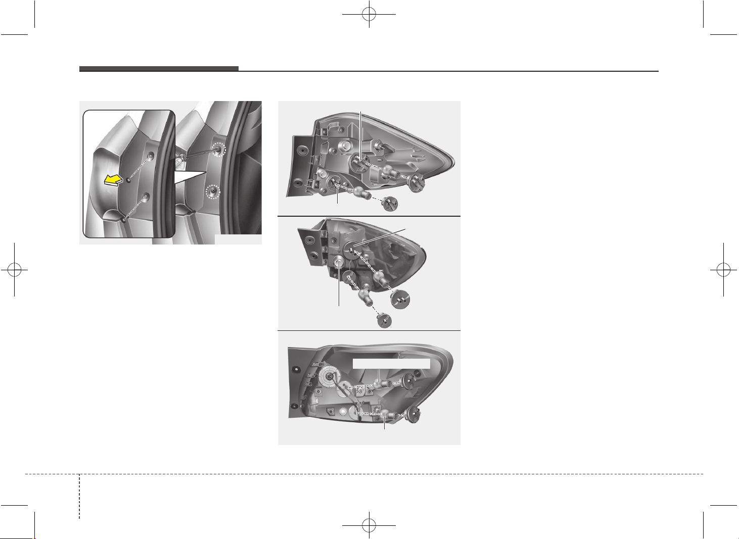
Maintenance
947
❈ The actual rear combination lamp shape in
the vehicle may differ from illustration.
Outside light
Rear turn signal light and stop/tail light
1. Turn off the engine.
2. Open the tailgate.
3. Loosen the light assembly retaining
screws with a cross-tip screwdriver.
4. Remove the rear combination light
assembly from the body of the vehicle.
5. Remove the socket from the assembly
by turning the socket counterclockwise
until the tabs on the socket align with
the slots on the assembly.
6. Remove the bulb from the socket by
pressing it in and rotating it counter-
clockwise until the tabs on the bulb
align with the slots in the socket. Pull
the bulb out of the socket.
7. Insert a new bulb by inserting it into
the socket and rotating it until it locks
into place.
8. Install the socket in the assembly by
aligning the tabs on the socket with the
slots in the assembly. Push the socket
into the assembly and turn the socket
clockwise.
9. Reinstall the light assembly to the
body of the vehicle.
OJD072057
OJD072064
■ 5 Door
■ Wagon
OJD073073
■ 3 Door
Turn signal light
Stop/tail light
Stop or Stop/tail light
Turn signal light
Stop/tail light
OJD072045
Turn signal light
JD PE eng 7.QXP 03.01.2017 17:23 Page 94
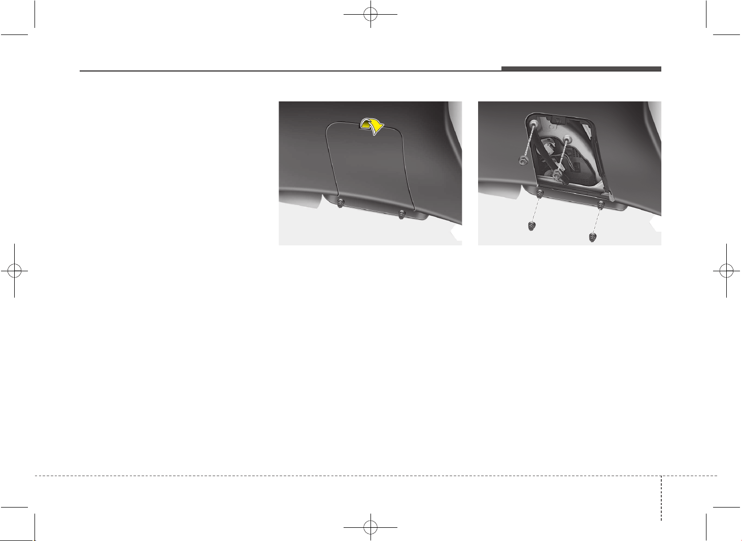
795
Maintenance
Stop and tail light or tail light (LED type)
If the light does not operate, we recom-
mend that the system be checked by an
authorized Kia dealer.
Inside light (5 Door and Wagon)
1. Turn off the engine.
2. Open the tailgate.
3. Remove the service cover using a flat-
blade screwdriver.
❈ These below steps (4~6) only for the 5 Door
vehicle.
4. Loosen the retaining nuts.
5. Disconnect the power connector.
6. Remove the rear combination light
assembly from the body of the vehicle.
OJD072048OJD072047
JD PE eng 7.QXP 03.01.2017 17:23 Page 95
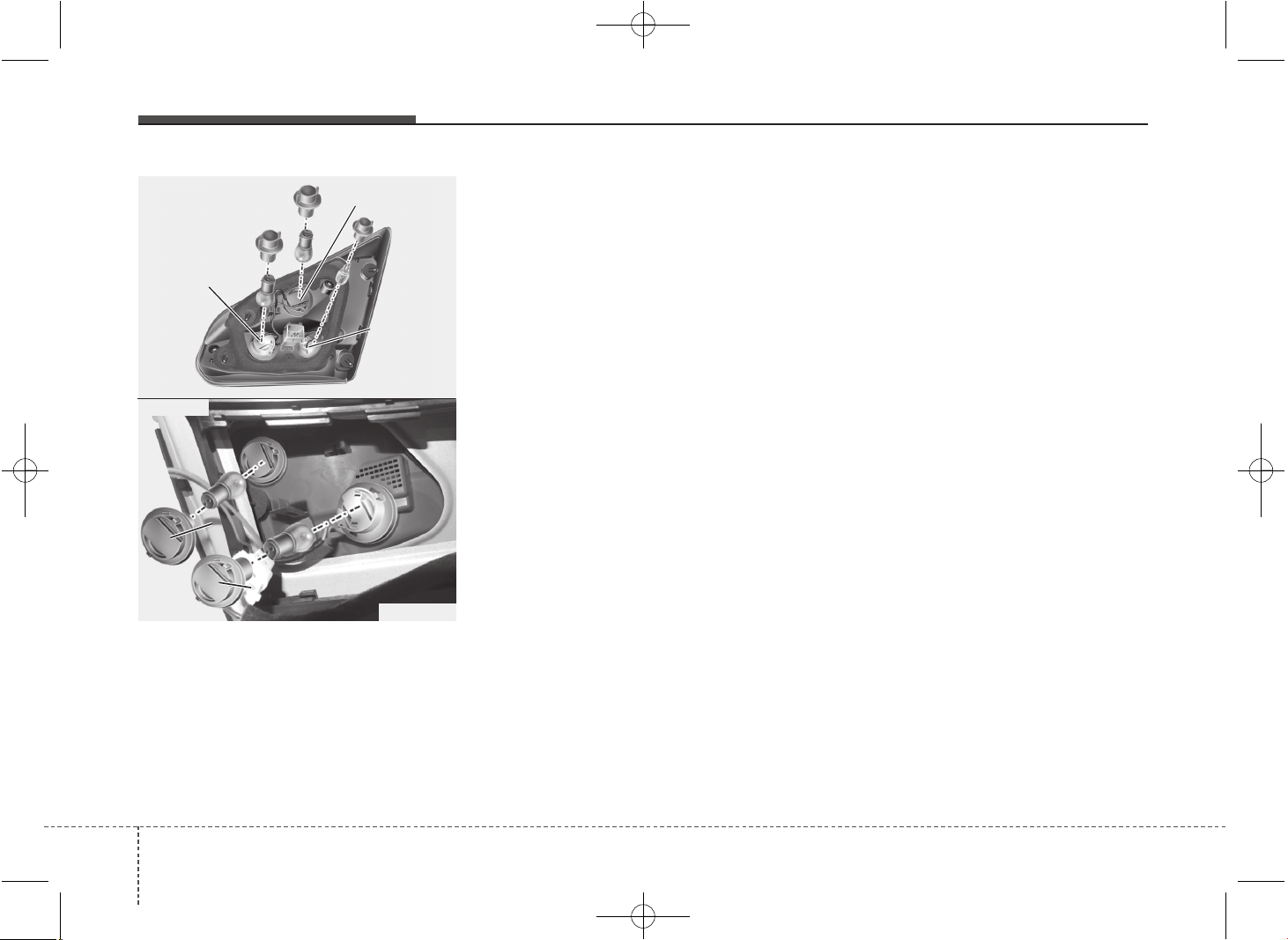
Maintenance
967
❈ Rear fog light is located only on the driver’s
side (for wagon)
Tail light or tail and stop light (Bulb type)
7. Remove the socket from the assembly
by turning the socket counterclockwise
until the tabs on the socket align with
the slots on the assembly.
8. Remove the bulb from the socket by
pressing it in and rotating it counter-
clockwise until the tabs on the bulb
align with the slots in the socket. Pull
the bulb out of the socket.
9. Insert a new bulb by inserting it into
the socket and rotating it until it locks
into place.
10. Install the socket in the assembly by
aligning the tabs on the socket with
the slots in the assembly. Push the
socket into the assembly and turn the
socket clockwise.
11. Install the service cover by putting it
into the service hole.
Back-up light and rear fog light
(5 Door and Wagon) (if equipped)
7. Remove the socket from the assembly
by turning the socket counterclockwise
until the tabs on the socket align with
the slots on the assembly.
8. Pull the bulb out of the socket.
9. Insert a new bulb into the socket.
10. Install the socket into the assembly
by aligning the tabs on the socket
with the slots on the assembly and
turning the socket clockwise.
11. Reinstall the light assembly to the
body of the vehicle
❈ Rear fog light is located only on the
driver’s side. (for wagon)
OJD072058
■ 5 Door
■ Wagon
Rear fog light
Back up light
Stop light
OJD072065
RR
RR
ee
ee
aa
aa
rr
rr
ff
ff
oo
oo
gg
gg
//
//
BB
BB
aa
aa
cc
cc
kk
kk
uu
uu
pp
pp
ll
ll
ii
ii
gg
gg
hh
hh
tt
tt
TT
TT
aa
aa
ii
ii
ll
ll
ll
ll
ii
ii
gg
gg
hh
hh
tt
tt
JD PE eng 7.QXP 03.01.2017 17:23 Page 96
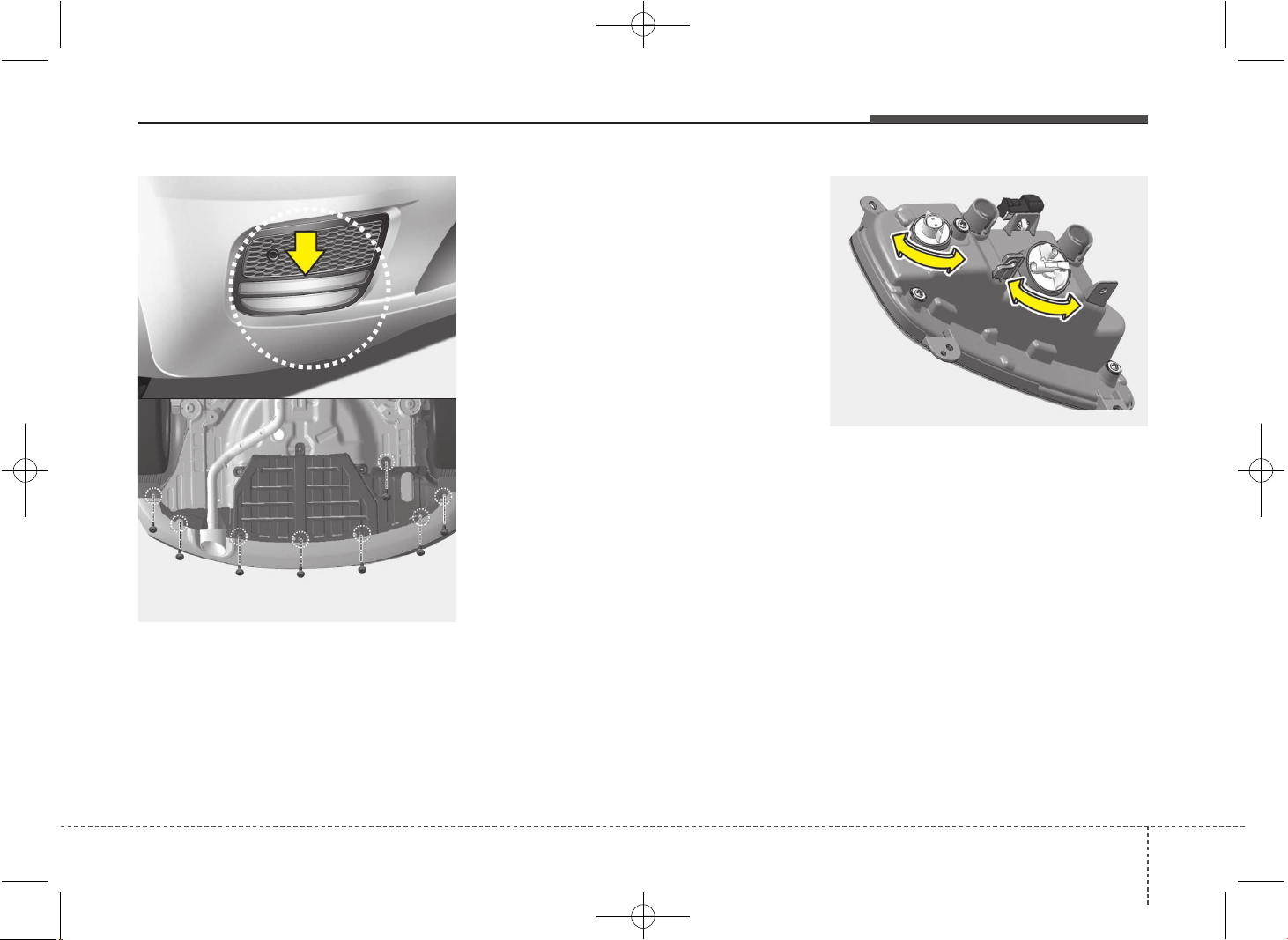
797
Maintenance
Rear fog light (if equipped)
1. Remove the under cover by rotating
the screws.
2. Reach your hand into the back of the
rear bumper.
3. Disconnect the power connector.
4. Remove the bulb-socket from the
housing by turning the socket counter
clockwise until the tabs on the socket
align with the slots on the housing.
5.Install the new bulb-socket into the
housing by aligning the tabs on the
socket with the slots in the housing.
Push the socket into the housing and
turn the socket clockwise.
6.Connect the power connector.
7.Reinstall the rear under cover.
✽✽
NOTICE
Rear fog light is only on the driver’s side
(5 door, if equipped).
OJD073075
OJD075071
OJD073074
JD PE eng 7.QXP 03.01.2017 17:23 Page 97
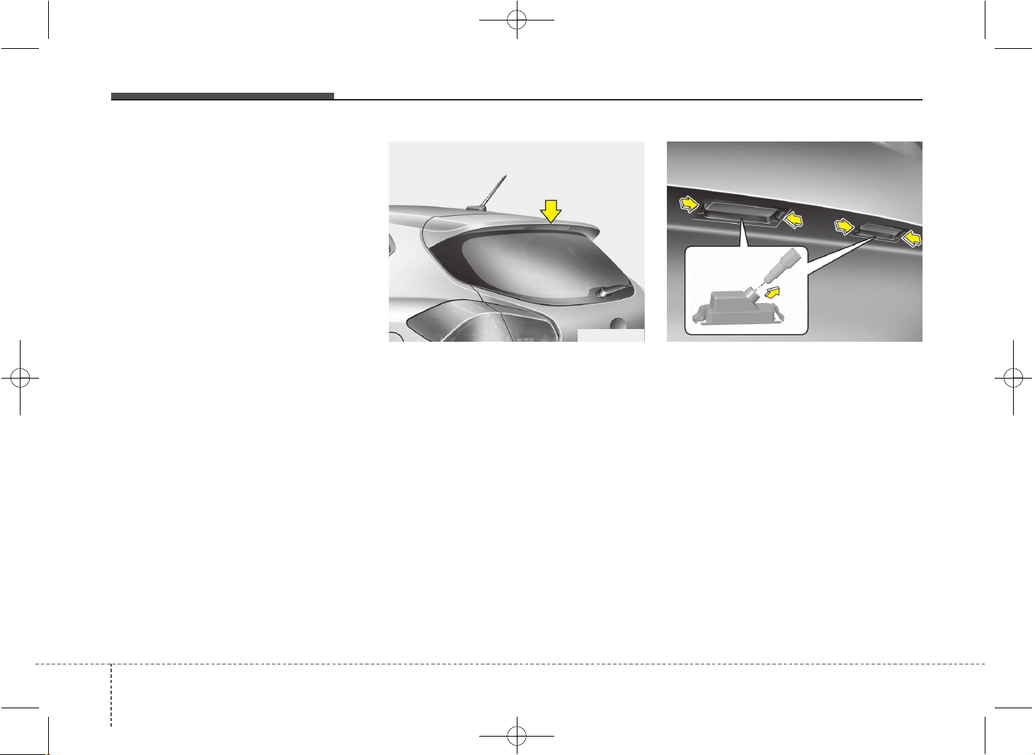
Maintenance
987
Tail light or stop and tail light (LED type)
If the light does not operate, we recom-
mend that the system be checked by an
authorized Kia dealer.
High mounted stop light bulb
replacement
If the light does not operate, we recom-
mend that the system be checked by an
authorized Kia dealer.
License plate light bulb replace-
ment
1. Turn off the engine.
2. Remove the bulb assembly by press-
ing the tabs.
3. Remove the socket by turning it coun-
terclockwise.
4. Remove the bulb by pulling it straight
out.
5. Install a new bulb.
6. Reinstall the bulb assembly securely
with the retaining screws.
OJD072037 OGD071046
JD PE eng 7.QXP 03.01.2017 17:24 Page 98
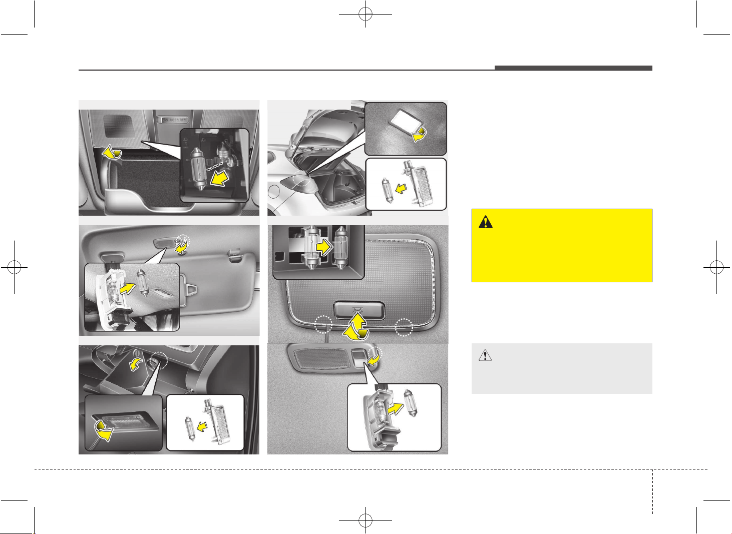
799
Maintenance
Interior light bulb replacement
Map lamp, vanity mirror lamp,
room lamp, luggage room lamp
and glove box lamp
1. Using a flat-blade screwdriver, gently
pry the lens from the interior light
housing.
2. Remove the bulb by pulling it straight
out.
3. Install a new bulb in the socket.
4. Align the lens tabs with the interior
light housing notches and snap the
lens into place.
■ Map lamp
■ Glove box lamp
■ Vanity mirror lamp
■ Luggage room lamp
■ Room lamp
OGD071039/OTD079035/OJD072043/OJD072038/OGDE071057/OGD071038
--
--
TT
TT
yy
yy
pp
pp
ee
ee
AA
AA
--
--
TT
TT
yy
yy
pp
pp
ee
ee
BB
BB
WARNING
Prior to working on the interior
lights, ensure that the light is off to
avoid burning your fingers or
receiving an electric shock.
CAUTION
Be careful not to dirt or damage
lens, lens tab, and plastic housings.
JD PE eng 7.QXP 03.01.2017 17:24 Page 99
Maintenance
1007
APPEARANCE CARE
Exterior care
Exterior general caution
It is very important to follow the label
directions when using any chemical clean-
er or polish. Read all warning and caution
statements that appear on the label.
Finish maintenance
Washing
To help protect your vehicle’s finish from
rust and deterioration, wash it thoroughly
and frequently at least once a month with
lukewarm or cold water.
If you use your vehicle for off-road driv-
ing, you should wash it after each off-
road trip. Pay special attention to the
removal of any accumulation of salt, dirt,
mud, and other foreign materials. Ensure
drain holes in the lower edges of the
doors and rocker panels are kept clean.
Insects, tar, tree sap, bird droppings,
industrial pollution and similar deposits
can damage your vehicle’s finish if not
removed immediately.
Even prompt washing with plain water may
not completely remove all these deposits.
A mild soap, safe for use on painted sur-
faces, may be used.
After washing, rinse the vehicle thor-
oughly with lukewarm or cold water. Do
not allow soap to dry on the finish.
High-pressure washing
When using the High Pressure car wash
system for cleaning the exterior of your
vehicle, be aware that without following
the proper precautions, it may damage
your car.
• Never let the high pressure car wash
nozzle come too close to the windows,
soft materials, light system (headlights,
taillights and such), camera, sensors,
bumpers, rubber (including tires), and
also the underside of the vehicle.
• The high pressure could damage
these parts especially if injected from a
short distance.
Never clean a specific point on the
vehicle for a prolonged time. Applying
the high pressure car wash nozzle for
a prolonged time it could damage and
harm the vehicle.
• Even while the high pressure car wash
nozzle is applied from a distance for a
limited time only, always bear in mind
that a direct stream would greatly
affect the surface of the vehicle.
• Always use high pressure car washes
which supply jet spray nozzle system,
not direct stream nozzle system
WARNING - Wet brakes
After washing the vehicle, test the
brakes while driving slowly to see if
they have been affected by water. If
braking performance is impaired,
dry the brakes by applying them
lightly while maintaining a slow for-
ward speed.
CAUTION
• Do not use strong soap, chemical
detergents or hot water, and do
not wash the vehicle in direct
sunlight or when the body of the
vehicle is warm.
• Be careful when washing the side
windows of your vehicle.
Especially, with high-pressure
water, water may leak through the
windows and wet the interior.
• To prevent damage to the plastic
parts and lamps, do not clean
with chemical solvents or strong
detergents.
JD PE eng 7.QXP 03.01.2017 17:24 Page 100
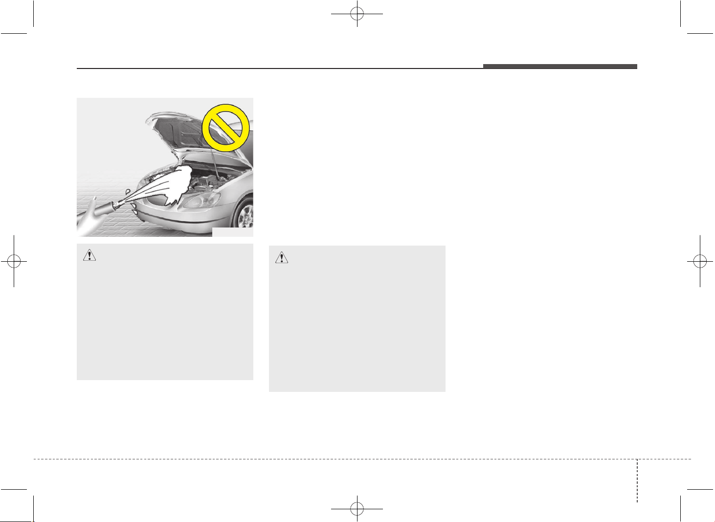
7101
Maintenance
Waxing
Wax the vehicle when water will no
longer bead on the paint.
Always wash and dry the vehicle before
waxing. Use a good quality liquid or
paste wax, and follow the manufacturer’s
instructions. Wax all metal trim to protect
it and to maintain its luster.
Removing oil, tar, and similar materials
with a spot remover will usually strip the
wax from the finish. Be sure to re-wax
these areas even if the rest of the vehicle
does not yet need waxing.
Finish damage repair
Deep scratches or stone chips in the
painted surface must be repaired
promptly. Exposed metal will quickly rust
and may develop into a major repair
expense.
✽✽
NOTICE
If your vehicle is damaged and requires
any metal repair or replacement, be sure
the body shop applies anti-corrosion
materials to the parts repaired or
replaced.
CAUTION
• Wiping dust or dirt off the body
with a dry cloth will scratch the
finish.
• Do not use steel wool, abrasive
cleaners, or strong detergents
containing highly alkaline or
caustic agents on chrome-plated
or anodized aluminum parts. This
may result in damage to the pro-
tective coating and cause discol-
oration or paint deterioration.
CAUTION
• Water washing in the engine com-
partment including high pressure
water washing may cause the fail-
ure of electrical circuits located in
the engine compartment.
• Never allow water or other liquids
to come in contact with electri-
cal/electronic components and
air duct inside the vehicle as this
may damage them.
OJB037800
JD PE eng 7.QXP 03.01.2017 17:24 Page 101
Maintenance
1027
Bright-metal maintenance
• To remove road tar and insects, use a
tar remover, not a scraper or other
sharp object.
• To protect the surfaces of bright-metal
parts from corrosion, apply a coating of
wax or chrome preservative and rub to
a high luster.
• During winter weather or in coastal
areas, cover the bright metal parts with
a heavier coating of wax or preserva-
tive. If necessary, coat the parts with
non-corrosive petroleum jelly or other
protective compound.
Underbody maintenance
Corrosive materials used for ice and
snow removal and dust control may col-
lect on the underbody. If these materials
are not removed, accelerated rusting can
occur on underbody parts such as the
fuel lines, frame, floor pan and exhaust
system, even though they have been
treated with rust protection.
Thoroughly flush the vehicle underbody
and wheel openings with lukewarm or
cold water once a month, after off-road
driving and at the end of each winter. Pay
special attention to these areas because
it is difficult to see all the mud and dirt. It
will do more harm than good to wet down
the road grime without removing it. The
lower edges of doors, rocker panels, and
frame members have drain holes that
should not be allowed to clog with dirt;
trapped water in these areas can cause
rusting.
WARNING
After washing the vehicle, test the
brakes while driving slowly to see if
they have been affected by water. If
braking performance is impaired,
dry the brakes by applying them
lightly while maintaining a slow for-
ward speed.
JD PE eng 7.QXP 03.01.2017 17:24 Page 102
7103
Maintenance
Aluminum wheel maintenance
The aluminum wheels are coated with a
clear protective finish.
• Do not use any abrasive cleaner, pol-
ishing compound, solvent, or wire
brushes on aluminum wheels. They
may scratch or damage the finish.
• Clean the wheel when it has cooled.
• Use only a mild soap or neutral deter-
gent, and rinse thoroughly with water.
Also, be sure to clean the wheels after
driving on salted roads. This helps pre-
vent corrosion.
• Avoid washing the wheels with high-
speed car wash brushes.
• Do not use any alkaline or acid deter-
gent. It may damage and corrode the
aluminum wheels coated with a clear
protective finish.
Corrosion protection
Protecting your vehicle from corrosion
By using the most advanced design and
construction practices to combat corro-
sion, we produce cars of the highest
quality. However, this is only part of the
job. To achieve the long-term corrosion
resistance your vehicle can deliver, the
owner's cooperation and assistance is
also required.
Common causes of corrosion
The most common causes of corrosion
on your car are:
• Road salt, dirt and moisture that is
allowed to accumulate underneath the
car.
• Removal of paint or protective coatings
by stones, gravel, abrasion or minor
scrapes and dents which leave unpro-
tected metal exposed to corrosion.
High-corrosion areas
If you live in an area where your car is
regularly exposed to corrosive materials,
corrosion protection is particularly impor-
tant. Some of the common causes of
accelerated corrosion are road salts,
dust control chemicals, ocean air and
industrial pollution.
Moisture breeds corrosion
Moisture creates the conditions in which
corrosion is most likely to occur. For
example, corrosion is accelerated by
high humidity, particularly when tempera-
tures are just above freezing. In such
conditions, the corrosive material is kept
in contact with the car surfaces by mois-
ture that is slow to evaporate.
Mud is particularly corrosive because it is
slow to dry and holds moisture in contact
with the vehicle. Although the mud
appears to be dry, it can still retain the
moisture and promote corrosion.
High temperatures can also accelerate
corrosion of parts that are not properly
ventilated so the moisture can be dis-
persed. For all these reasons, it is par-
ticularly important to keep your car clean
and free of mud or accumulations of
other materials. This applies not only to
the visible surfaces but particularly to the
underside of the car.
To help prevent corrosion
You can help prevent corrosion from get-
ting started by observing the following:
JD PE eng 7.QXP 03.01.2017 17:24 Page 103

Maintenance
1047
Keep your car clean
The best way to prevent corrosion is to
keep your car clean and free of corrosive
materials. Attention to the underside of
the car is particularly important.
• If you live in a high-corrosion area —
where road salts are used, near the
ocean, areas with industrial pollution,
acid rain, etc.—, you should take extra
care to prevent corrosion. In winter,
hose off the underside of your car at
least once a month and be sure to
clean the underside thoroughly when
winter is over.
• When cleaning underneath the car,
give particular attention to the compo-
nents under the fenders and other
areas that are hidden from view. Do a
thorough job; just dampening the accu-
mulated mud rather than washing it
away will accelerate corrosion rather
than prevent it. Water under high pres-
sure and steam are particularly effec-
tive in removing accumulated mud and
corrosive materials.
• When cleaning lower door panels,
rocker panels and frame members, be
sure that drain holes are kept open so
that moisture can escape and not be
trapped inside to accelerate corrosion.
Keep your garage dry
Don't park your car in a damp, poorly
ventilated garage. This creates a favor-
able environment for corrosion. This is
particularly true if you wash your car in
the garage or drive it into the garage
when it is still wet or covered with snow,
ice or mud. Even a heated garage can
contribute to corrosion unless it is well
ventilated so moisture is dispersed.
Keep paint and trim in good condition
Scratches or chips in the finish should be
covered with "touch-up" paint as soon as
possible to reduce the possibility of cor-
rosion. If bare metal is showing through,
the attention of a qualified body and paint
shop is recommended.
Bird droppings : Bird droppings are high-
ly corrosive and may damage painted
surfaces in just a few hours. Always
remove bird droppings as soon as possi-
ble.
Don't neglect the interior
Moisture can collect under the floor mats
and carpeting to cause corrosion. Check
under the mats periodically to be sure
the carpeting is dry. Use particular care if
you carry fertilizers, cleaning materials or
chemicals in the car.
These should be carried only in proper
containers and any spills or leaks should
be cleaned up, flushed with clean water
and thoroughly dried.
JD PE eng 7.QXP 03.01.2017 17:24 Page 104
7105
Maintenance
Interior care
Interior general precautions
Prevent chemicals such as perfume, cos-
metic oil, sun cream, hand cleaner, and
air freshener from contacting the interior
parts because they may cause damage
or discoloration. If they do contact the
interior parts, wipe them off immediately.
See the instructions that follow for the
proper way to clean vinyl.
Taking care of leather seats
• Vacuum the seat periodically to
remove dust and sand on the seat. It
will prevent abrasion or damage of the
leather and maintain its quality.
• Wipe the natural leather seat cover
often with dry or soft cloth.
• Sufficient use of a leather protective
may prevent abrasion of the cover and
helps maintain the color. Be sure to
read the instructions and consult a
specialist when using leather coating
or protective agents.
• Leather with bright colors(beige, cream
beige) is easily contaminated and clear
in appearance. Clean the seats fre-
quently.
• Avoid wiping with wet cloth. It may
cause the surface to crack.
Cleaning the leather seats
• Remove all contaminations instantly.
Refer to instructions below for removal
of each contaminant.
• Cosmetic products(sunscreen, founda-
tion, etc.)
- Apply cleansing cream on a cloth and
wipe the contaminated point. Wipe off
the cream with a wet cloth and
remove water with a dry cloth.
• Beverages(coffee, soft drink, etc.)
- Apply a small amount of neutral
detergent and wipe until contamina-
tions do not smear.
•Oil
- Remove oil instantly with absorbable
cloth and wipe with stain remover for
natural leather only.
• Chewing gum
- Harden the gum with ice and remove
gradually.
CAUTION
Never allow water or other liquids
to come in contact with
electrical/electronic components
inside the vehicle as this may dam-
age them.
CAUTION
When cleaning leather products
(steering wheel, seats etc.), use
neutral detergents or low alcohol
content solutions. If you use high
alcohol content solutions or
acid/alkaline detergents, the color
of the leather may fade or the sur-
face may get stripped off.
JD PE eng 7.QXP 03.01.2017 17:24 Page 105
Maintenance
1067
Fabric seat cover (If equipped)
Please clean the fabric seats regularly
with a vacuum cleaner in consideration of
fabric material characteristics. If they are
heavily soiled with beverage stains, etc.,
use a suitable interior cleaner. To prevent
damage to seat covers, wipe off the seat
covers down to the seams with a large
wiping motion and moderate pressure
using a soft sponge or microfiber cloth.
Velcro closures on clothing or sharp
objects may cause snagging or scratch-
es on the surface of the seats.
Make sure not to rub such objects
against the surface.
Cleaning the upholstery and interior
trim
Vinyl
Remove dust and loose dirt from vinyl
with a whisk broom or vacuum cleaner.
Clean vinyl surfaces with a vinyl cleaner.
Fabric
Remove dust and loose dirt from fabric
with a whisk broom or vacuum cleaner.
Clean with a mild soap solution recom-
mended for upholstery or carpets.
Remove fresh spots immediately with a
fabric spot cleaner. If fresh spots do not
receive immediate attention, the fabric
can be stained and its color can be
affected. Also, its fire-resistant properties
can be reduced if the material is not
properly maintained.
Cleaning the lap/shoulder belt web-
bing
Clean the belt webbing with any mild
soap solution recommended for cleaning
upholstery or carpet. Follow the instruc-
tions provided with the soap. Do not
bleach or re-dye the webbing because
this may weaken it.
Cleaning the interior window glass
If the interior glass surfaces of the vehi-
cle become fogged (that is, covered with
an oily, greasy or waxy film), they should
be cleaned with glass cleaner. Follow the
directions on the glass cleaner container.
CAUTION
Using anything but recommended
cleaners and procedures may affect
the fabric’s appearance and fire-
resistant properties.
CAUTION
Do not scrape or scratch the inside
of the rear window. This may result
in damage to the rear window
defroster grid.
JD PE eng 7.QXP 03.01.2017 17:24 Page 106

7107
Maintenance
EMISSION CONTROL SYSTEM
The emission control system of your
vehicle is covered by a written limited
warranty. Please see the warranty infor-
mation contained in the Warranty &
Maintenance book in your vehicle.
Your vehicle is equipped with an emis-
sion control system to meet all emission
regulations.
There are three emission control sys-
tems which are as follows.
(1) Crankcase emission control system
(2) Evaporative emission control system
(3) Exhaust emission control system
In order to assure the proper function of
the emission control systems, it is rec-
ommended that you have your car
inspected and maintained by an author-
ized Kia dealer in accordance with the
maintenance schedule.
Caution for the Inspection and
Maintenance Test (With Electronic
Stability Control (ESC) system)
• To prevent the vehicle from misfir-
ing during dynamometer testing,
turn the Electronic Stability Control
(ESC) system off by pressing the
ESC switch.
• After dynamometer testing is com-
pleted, turn the ESC system back on
by pressing the ESC switch again.
1. Crankcase emission control
system
The positive crankcase ventilation sys-
tem is employed to prevent air pollution
caused by blow-by gases being emitted
from the crankcase.This system supplies
fresh filtered air to the crankcase through
the air intake hose. Inside the crankcase,
the fresh air mixes with blow-by gases,
which then pass through the PCV valve
into the induction system.
2. Evaporative emission control
System
The Evaporative Emission Control
System is designed to prevent fuel
vapors from escaping into the atmos-
phere.
Canister
Fuel vapors generated inside the fuel
tank are absorbed and stored in the
onboard canister. When the engine is
running, the fuel vapors absorbed in the
canister are drawn into the surge tank
through the purge control solenoid valve.
Purge Control Solenoid Valve (PCSV)
The purge control solenoid valve is con-
trolled by the Engine Control Module
(ECM); when the engine coolant temper-
ature is low during idling, the PCSV clos-
es so that evaporated fuel is not taken
into the engine. After the engine warms-
up during ordinary driving, the PCSV
opens to introduce evaporated fuel to the
engine.
JD PE eng 7.QXP 03.01.2017 17:24 Page 107
Maintenance
1087
3. Exhaust emission control
system
The Exhaust Emission Control System is
a highly effective system which controls
exhaust emissions while maintaining
good vehicle performance.
Vehicle modifications
This vehicle should not be modified.
Modification of your vehicle could affect
its performance, safety or durability and
may even violate governmental safety
and emissions regulations.
In addition, damage or performance
problems resulting from any modification
may not be covered under warranty.
• If you use unauthorized electronic
devices, it may cause the vehicle to
operate abnormally, wire damage, bat-
tery discharge or fire. For your safety,
do not use unauthorized electric
devices.
Engine exhaust gas precautions
(carbon monoxide)
• Carbon monoxide can be present with
other exhaust fumes. Therefore, if you
smell exhaust fumes of any kind inside
your vehicle, have it inspected and
repaired immediately. If you ever sus-
pect exhaust fumes are coming into
your vehicle, drive it only with all the
windows fully open. Have your vehicle
checked and repaired immediately.
• Do not operate the engine in confined
or closed areas (such as garages) any
more than what is necessary to move
the vehicle in or out of the area.
• When the vehicle is stopped in an
open area for more than a short time
with the engine running, adjust the
ventilation system (as needed) to draw
outside air into the vehicle.
• Never sit in a parked or stopped vehi-
cle for any extended time with the
engine running.
• When the engine stalls or fails to start,
excessive attempts to restart the
engine may cause damage to the
emission control system.
WARNING - Exhaust
Engine exhaust gases contain car-
bon monoxide (CO). Though color-
less and odorless, it is dangerous
and could be lethal if inhaled.
Follow the instructions following to
avoid CO poisoning.
JD PE eng 7.QXP 03.01.2017 17:24 Page 108
7109
Maintenance
Operating precautions for catalytic
converters (if equipped)
Your vehicle is equipped with a catalytic
converter emission control device.
Therefore, the following precautions
must be observed:
• Make sure to refuel your vehicle
according to the "Fuel requirements"
suggested in chapter 1.
• Do not operate the vehicle when there
are signs of engine malfunction, such
as misfire or a noticeable loss of per-
formance.
• Do not misuse or abuse the engine.
Examples of misuse are coasting with
the ignition off and descending steep
grades in gear with the ignition off.
• Do not operate the engine at high idle
speed for extended periods (5 minutes
or more).
• Do not modify or tamper with any part
of the engine or emission control sys-
tem. We recommend that the system be
inspected by an authorized Kia dealer.
• Avoid driving with an extremely low fuel
level. Running out of fuel cause the
engine to misfire, damaging the cat-
alytic converter.
Failure to observe these precautions
could result in damage to the catalytic
converter and to your vehicle.
Additionally, such actions could void your
warranties.
Diesel Particulate Filter (if equipped)
The Diesel Particulate Filter (DPF) sys-
tem removes the soot in the exhaust gas.
Unlike a disposable air filter, the DPF
system automatically burns (oxidizes)
and removes the accumulated soot
according to the driving condition. In
other words, the active burning by engine
control system and high exhaust gas
temperature caused by normal/high driv-
ing condition burns and removes the
accumulated soot.
However, if the vehicle continues to be
driven at repeated short
distance or driven at low speed for a long
time, the accumulated soot may not be
automatically removed because of low
exhaust gas temperature. More than a
certain amount of soot deposited, the
malfunction indicator light ( ) illumi-
nates.
When the malfunction indicator light
blinks, it may stop blinking by driving the
vehicle at more than 60km/h (37 mph) or
at more than second gear with 1500 ~
2500 engine rpm for a certain time (for
about 25 minutes).
WARNING - Fire
• A hot exhaust system can ignite
flammable items under your vehi-
cle. Do not park, idle, or drive the
vehicle over or near flammable
objects, such as dry grass, paper,
leaves, etc.
• The exhaust system and catalytic
system are very hot while the
engine is running or immediately
after the engine is turned off.
Keep away from the exhaust sys-
tem and catalytic, you may get
burned.
Also, do not remove the heat sink
around the exhaust system, do
not seal the bottom of the vehicle
or do not coat the vehicle for cor-
rosion control. It may present a
fire risk under certain conditions.
JD PE eng 7.QXP 03.01.2017 17:24 Page 109
If the malfunction indicator light contin-
ues to be blinked in spite of the proce-
dure, we recommend that the system be
checked by an authorized Kia dealer.
If you continue to drive with the malfunc-
tion indicator light blinking for a long
time, the DPF system can be damaged
and fuel consumption can be worsen.
Lean NOx Trap (if equipped)
The Lean NOx Trap (LNT) system
removes the nitrogen oxide in the
exhaust gas. The smell can occur in the
exhaust gas depending on the quality of
the fuel and it can degrade NOx reduc-
tion performance, please use the regulat-
ed automotive diesel fuel.
CAUTION - Diesel Fuel
(if equipped with DPF)
It is recommended to use the regu-
lated automotive diesel fuel for
diesel vehicle equipped with the
DPF system.
If you use diesel fuel including high
sulfur (more than 50 ppm sulfur) and
unspecified additives, it can cause
the DPF system to be damaged and
white smoke can be emitted.
7 110
Maintenance
JD PE eng 7.QXP 03.01.2017 17:24 Page 110

Specifications & Consumer information
Dimensions . . . . . . . . . . . . . . . . . . . . . . . . . . . . . . . . 8-2
Engine . . . . . . . . . . . . . . . . . . . . . . . . . . . . . . . . . . . . 8-3
Air conditioning system. . . . . . . . . . . . . . . . . . . . . . 8-4
Gross vehicle weight . . . . . . . . . . . . . . . . . . . . . . . . 8-5
Luggage volume . . . . . . . . . . . . . . . . . . . . . . . . . . . . 8-5
Bulb wattage . . . . . . . . . . . . . . . . . . . . . . . . . . . . . . . 8-6
Tires and wheels. . . . . . . . . . . . . . . . . . . . . . . . . . . . 8-8
Recommended lubricants and capacities . . . . . . . 8-9
• Recommended SAE viscosity number . . . . . . . . . . . . 8-12
Vehicle identification number (VIN) . . . . . . . . . . . 8-13
Vehicle certification label . . . . . . . . . . . . . . . . . . . . 8-13
Tire specification and pressure label . . . . . . . . . . . 8-14
Engine number . . . . . . . . . . . . . . . . . . . . . . . . . . . . . 8-14
Air conditioner compressor label . . . . . . . . . . . . . . 8-15
Refrigerant label . . . . . . . . . . . . . . . . . . . . . . . . . . . 8-15
Declaration of conformity . . . . . . . . . . . . . . . . . . . . 8-15
8

Specifications & Consumer information
28
DIMENSIONS
Item
mm (in)
3 Door 5 Door Wagon
Overall length 4,310 (169.7) 4,310 (169.7) 4,505 (177.4)
Overall width
1,780 (70.1)
2,035 (80.1) *
1
1,780 (70.1)
2,035 (80.1) *
1
1,780 (70.1)
2,035 (80.1) *
1
Overall height
Except Russia
1,430 (56.3)
1,425 (56.1) *
2
1,470 (57.9)
1,465 (57.7) *
2
1,485 (58.5)
1,480 (58.3) *
2
For Russia 1,440 (56.7) 1,480 (58.3) 1,495 (58.9)
Front tread
195/65R15 Steel wheel 1,563 (61.5) 1,563 (61.5) 1,563 (61.5)
205/55R16
Steel wheel 1,553 (61.1) 1,553 (61.1) 1,553 (61.1)
Aluminum wheel 1,555 (61.2) 1,555 (61.2) 1,555 (61.2)
225/45R17 Aluminum wheel 1,549 (61.0) 1,549 (61.0) 1,549 (61.0)
225/40R18 Aluminum wheel 1,545 (60.8) 1,545 (60.8) -
Rear tread
195/65R15 Steel wheel 1,571 (61.9) 1,571 (61.9) 1,571 (61.9)
205/55R16
Steel wheel 1,561 (61.5) 1,561 (61.5) 1,561 (61.5)
Aluminum wheel 1,563 (61.5) 1,563 (61.5) 1,563 (61.5)
225/45R17 Aluminum wheel 1,557 (61.3) 1,557 (61.3) 1,557 (61.3)
225/40ZR18 Aluminum wheel 1,553 (61.1) 1,553 (61.1) -
Wheelbase 2,650 (104.3)
*
1
: Width including outside mirrors (except T-GDI engine)
*
2
: Emission Package

83
Specifications & Consumer information
ENGINE
Item Gasoline 1.0 Gasoline 1.4 Gasoline 1.6 Diesel 1.4 Diesel 1.6
Displacement cc
(cu. in)
998 (60.9) 1,368 (83.48) 1,591 (97.09) 1,396 (85.12)
1,582 (96.53)
Bore x Stroke mm
(in.)
71 x 84
(2.80 x 3.31)
72x84
(2.83x3.31)
77x85.44
(3.03x3.36)
75x79
(2.95x3.11)
77.2x84.5
(3.03x3.32)
Firing order 1-2-3 1-3-4-2 1-3-4-2 1-3-4-2 1-3-4-2
No. of cylinders 3, In-line 4, in-line 4, In-line 4, In-line
4, In-line

Specifications & Consumer information
48
AIR CONDITIONING SYSTEM
Item Weight or Volume Classification
Refrigerant 500±25g R-1234yf
Compressor lubricant 110±10g PAG (FD46XG)
For vehicles equipped with R-1234yf *
For vehicles equipped with R-134a *
Item Weight or Volume Classification
Refrigerant 500±25g R-134a
Compressor lubricant 110±10g PAG (FD46XG)
*: Your vehicle is filled with R-134a or R-1234yf according to the regulation in your country at the time of producing.
You can find out which air conditioning refrigerant is applied your vehicle at the label inside of hood.
Refer to chapter 8 for more detail location of air conditioning refrigerant label.
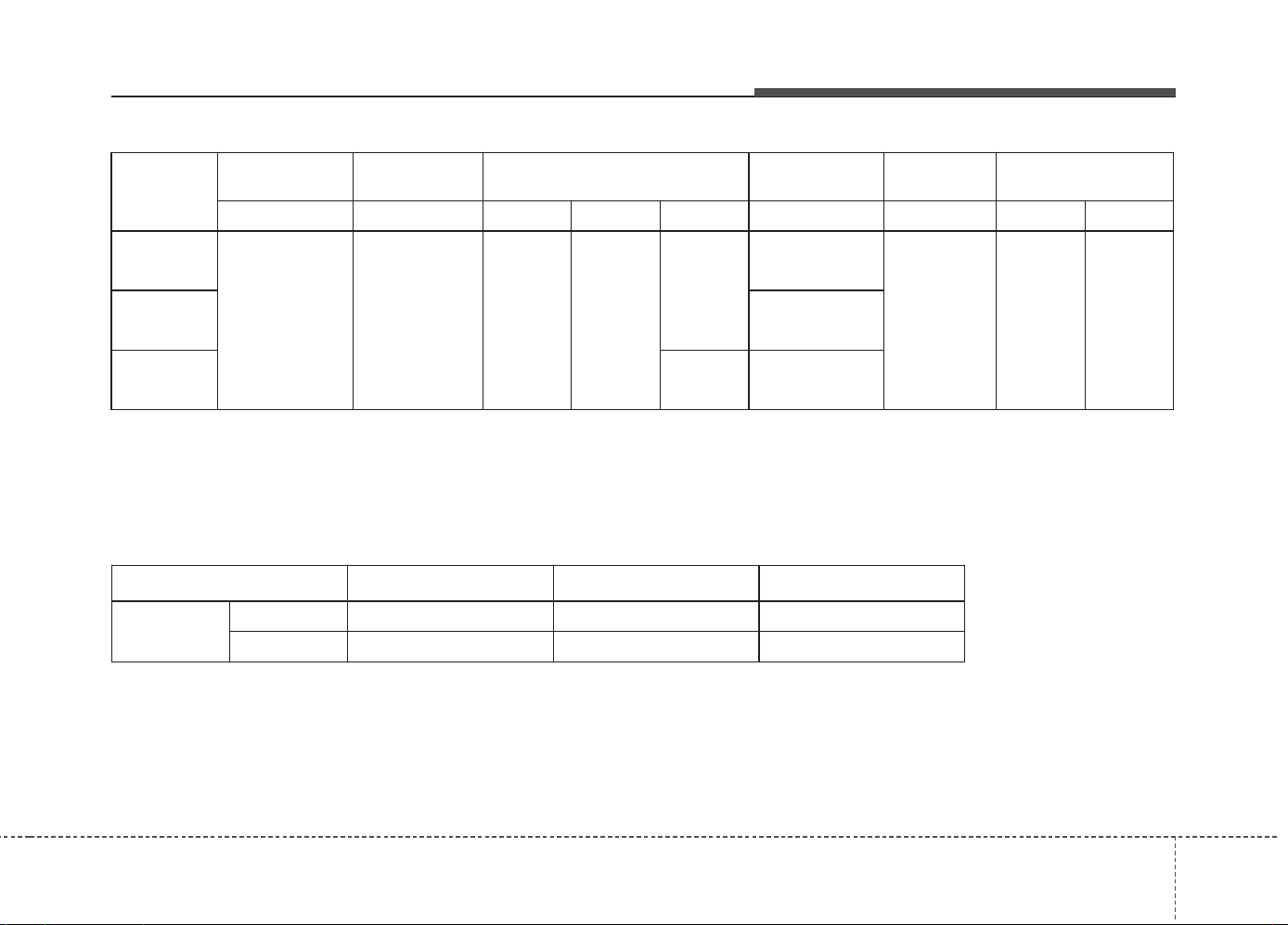
85
Specifications & Consumer information
Item 5 Door 3 Door Wagon
VDA
MIN. 380L (13.42 cu ft) 380L (13.42 cu ft) 528L (18.65 cu ft)
MAX. 1,318L (46.54 cu ft) 1,225L (42.26 cu ft) 1,642L (57.99 cu ft)
GROSS VEHICLE WEIGHT
M/T : Manual transaxle
A/T : Automatic transaxle
DCT : Double clutch transaxle
Min. : Behind rear seat to upper edge of the seat back.
Max. : Behind front seat to roof.
Item
Gasoline 1.0L
(T-GDI)
Gasoline 1.4L Gasoline 1.6L (MPI/GDI)
Gasoline 1.6L
(T-GDI)
Diesel 1.4L Diesel 1.6L
M/T M/T M/T A/T DCT M/T M/T M/T DCT
5 Door
1,820
(4,012)
1,820
(4,012)
1,820
(4,012)
1,850
(4,079)
1,840
(4,057)
1,870
(4,123)
1,910
(4,211)
1,920
(4,232)
1,940
(4,277)
3 Door
1,850
(4,079)
Wagon
1,850
(4,079)
-
LUGGAGE VOLUME

Specifications & Consumer information
68
BULB WATTAGE
Light Bulb
5 Door 3 Door Wagon
Wattage (W) Bulb type Wattage (W) Bulb type Wattage (W) Bulb type
Front
Headlights
Low
55 or 35
(AFLS with
HID)
H7LL or D1S*
55 or 35
(AFLS with
HID)
H7LL or D1S*
55 or 35
(AFLS with
HID)
H7LL or D1S*
High 55 H7LL 55 H7LL 55 H7LL
Static bending light* 55 H7LL 55 H7LL 55 H7LL
Daytime running light at
bumper (GTI)
21 (LED)
P21/5WXL
(LED)
21 (LED)
P21/5WXL
(LED)
21(LED)
P21/5WXL
(LED)
Daytime running light +
Position lights* at h/lamp
LED LED LED LED LED LED
Front turn signal lights 21 PY21WLL 21 PY21WLL 21 PY21WLL
Position lights 5/LED W5WLL/LED 5/LED W5WLL/LED 5/LED W5WLL/LED
Side repeater lights 5 5W 5 5W 5 5W
Puddle lamps* LED LED LED LED LED LED
Front fog lights(GTI) 51W(35W) 9006(H8L) 51W(35W) 9006(H8L) 51W(35W) 9006(H8L)
Rear
Rear fog light 21 P21WL 21 P21WL 21 P21WL
Stop and tail lights 21 P21/5WL 21/5 or LED
P21/5WL or
LED
21 P21/5WL
Rear turn signal lights 21 P21WL 21 P21WL 21 P21WL
Tail light 5 or LED
P21/5WL or
LED
5 or LED
P21/5WL or
LED
5 or LED
P21WL or
LED
Back-up lights 16 W16W 16 W16W 16 W16W
High mounted stop light LED LED LED LED LED LED
License plate lights 5 W5W 5 W5W 5 W5W
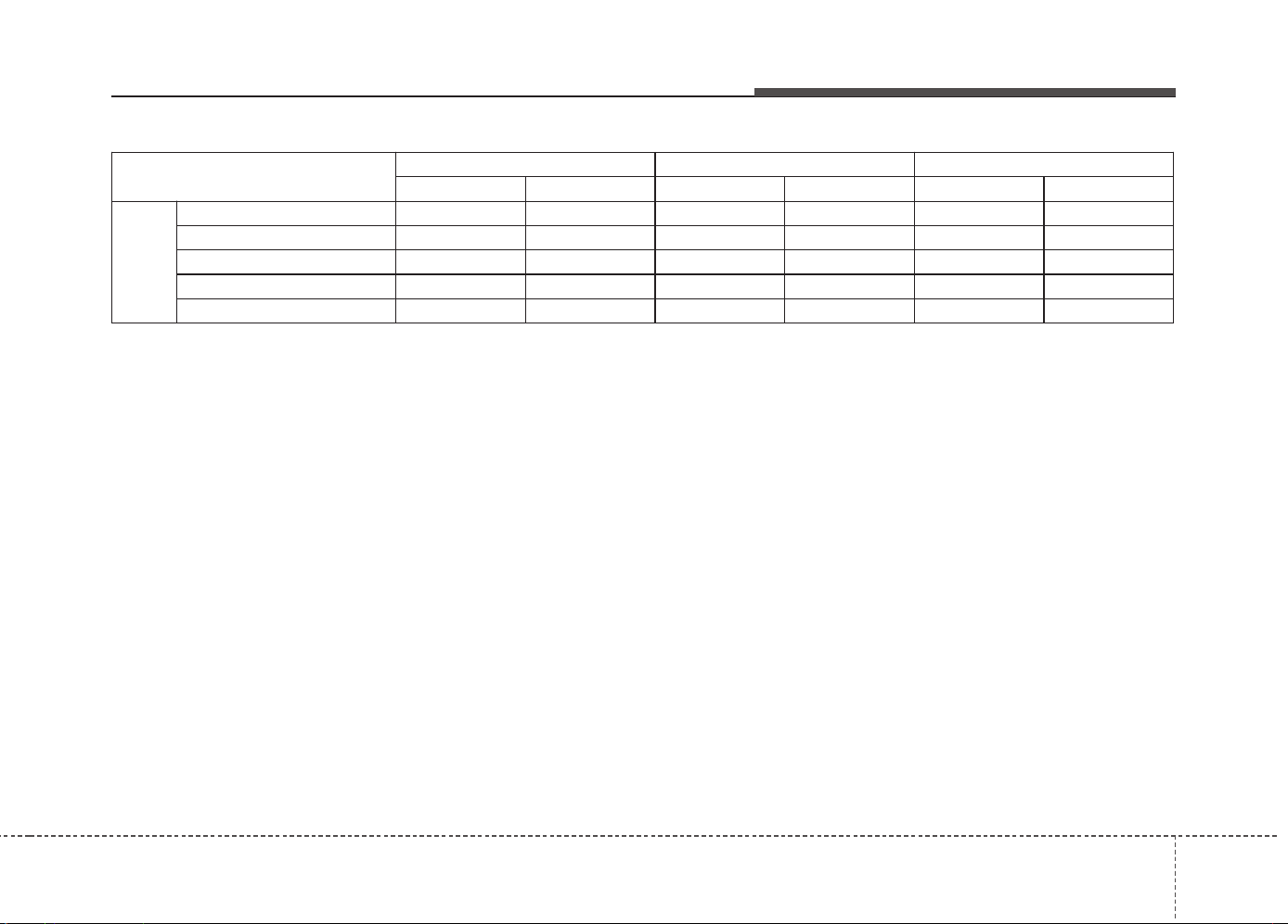
87
Specifications & Consumer information
Light Bulb
5 Door 3 Door Wagon
Wattage (W) Bulb type Wattage (W) Bulb type Wattage (W) Bulb type
Interior
Map lamps 8 FESTOON 8 FESTOON 8 FESTOON
Room lamps 8 FESTOON 8 FESTOON 8 FESTOON
Luggage lamp 8 FESTOON 8 FESTOON 8 FESTOON
Glove box lamp 5 FESTOON 5 FESTOON 5 FESTOON
Vanity mirror lamps 5 FESTOON 5 FESTOON 5 FESTOON
HID : High Intensity Discharge
AFLS : Adaptive Front-Lighting System
* : if equipped

Specifications & Consumer information
88
TIRES AND WHEELS
*
1
: Load Index
*
2
: Speed Symbol
*
3
: For 1.0 T-GDI Low Power Engine
Item Tire size
Wheel
size
Load Capacity Speed capacity
Inflation pressure bar(psi, kPa)
Wheel lug nut
torque Kgf·m
(lbf·ft, N·m)
Normal load Maximum load
LI *
1
Kg SS *
2
Km/h Front Rear Front Rear
Full size
tire
195/65R15 *
3
6.0J×15 91 615 H 210
2.5
(36,250)
2.5
(36,250)
2.5
(36,250)
2.5
(36,250)
9~11
(65~79, 88~107)
195/65R15 6.0J×15 91 615 H 210
2.5
(36,250)
2.5
(36,250)
2.5
(36,250)
2.5
(36,250)
205/55R16 6.5J×16 91 615 H 210
2.2
(32,220)
2.2
(32,220)
2.2
(32,220)
2.2
(32,220)
225/45R17 7.0J×17 91 615 V 240
2.2
(32,220)
2.2
(32,220)
2.2
(32,220)
2.2
(32,220)
225/45R17
(Sports pack)
7.0J×17 91 615 V 240
2.35
(34,235)
2.35
(34,235)
2.35
(34,235)
2.35
(34,235)
225/40ZR18 7.5J×18 92 630 Y 300
2.35
(34,235)
2.35
(34,235)
2.35
(34,235)
2.35
(34,235)
Compact
spare tire
T125/80D15 4.0T×15 95 690 M 130
4.2
(60, 420)
4.2
(60, 420)
4.2
(60, 420)
4.2
(60, 420)
T125/80D16 4.0T×16 97 730 M 130
4.2
(60, 420)
4.2
(60, 420)
4.2
(60, 420)
4.2
(60, 420)
✽✽
NOTICE
• We recommend that when replacing tires, use the same originally supplied with the vehicles.
If not, that affects driving performance.
• When driving in high altitude grades, it is natural for the atmospheric pressure to decrease. Therefore, please check the tire
pressure and add more air when necessary.
Additionally required tire air pressure per km above sea level: 1.5psi/km
89
Specifications & Consumer information
To help achieve proper engine and powertrain performance and durability, use only lubricants of the proper quality. The correct
lubricants also help promote engine efficiency that results in improved fuel economy.
These lubricants and fluids are recommended for use in your vehicle.
RECOMMENDED LUBRICANTS AND CAPACITIES
Lubricant Volume Classification
Engine oil *
1
*
2
(drain and refill)
Recommends
(or equivalent)
Gasoline
Engine *
4
Kappa 1.0 T-GDI 3.6 L (3.8 US qt.) ACEA A5 or above / 5W-30
Kappa 1.4 MPI 3.6 L (3.8 US qt.)
For Europe, MIDDLE EAST, North AFRICA :
5W-30 ACEA A5/B5
Except Europe, MIDDLE EAST, North AFRICA :
5W-20 ILSAC GF-4(or above), API SM, ACEA A5/B5
Gamma 1.6 MPI 3.6 L (3.8 US qt.)
For Europe, Egypt : ACEA A5 or above / 5W-30
Except Europe, Egypt : ILSAC GF-4 & API SM,
ACEA A5 or above / 5W-20
Gamma 1.6 GDI 3.6 L (3.8 US qt.) ACEA A5 or above / 5W-30
Gamma 1.6 T-GDI 4.5 L (4.75 US qt.)
For Europe : ACEA A5 / 5W-30
Except Europe : ACEA A5 / 5W-40
Diesel
Engine
U II 1.4 WGT
5.3 L (5.60 US qt.)
With DPF*
3
: ACEA C2 / 0W-30
Without DPF*
3
: ACEA B4 / 5W-30
U II 1.6 VGT

Specifications & Consumer information
108
Lubricant Volume Classification
Manual transaxle
fluid
Gasoline
Engine
Kappa 1.0 T-GDI
1.6 ~ 1.7 L
(1.69 ~ 1.80 US qt.)
SAE 70W, API GL-4
(Recommended SK HK MTF 70W, SHELL SPIRAX S6
GHME 70W, GS CALTEX GS MTF HD 70W)
Kappa 1.4 MPI
1.6 ~ 1.7 L
(1.69 ~ 1.80 US qt.)
Gamma 1.6 MPI
1.6 ~ 1.7 L
(1.69 ~ 1.80 US qt.)
Gamma 1.6 GDI
1.6 ~ 1.7 L
(1.69 ~ 1.80 US qt.)
Gamma 1.6 T-GDI
1.7 ~ 1.8 L
(1.80 ~ 1.90 US qt.)
Diesel
Engine
U II 1.4 WGT
1.7 ~ 1.8 L
(1.80 ~ 1.90 US qt.)
U II 1.6 VGT
1.7 ~ 1.8 L
(1.80 ~ 1.90 US qt.)
Automatic transaxle
fluid
Gasoline
Engine
Gamma 1.6 MPI 7.3 L (7.71 US qt.) ATF SP-IV
Dual clutch
transmission fluid
Gasoline
Engine
Gamma 1.6 GDI
1.9 ~ 2.0 L
(2.01 ~ 2.11 US qt.)
SAE 70W, API GL-4
(Recommended SK HK MTF 70W, SHELL SPIRAX S6
GHME 70W, GS CALTEX GS MTF HD 70W)
Diesel
Engine
U II 1.6 VGT
1.9 ~ 2.0 L
(2.01 ~ 2.11 US qt.)
811
Specifications & Consumer information
Recommends Engine oil (For Europe)
*
1
Refer to the recommended SAE viscosity numbers on next page.
*
2
Engine oils labeled Energy Conserving Oil are now available. Along with other additional benefits, they contribute to fuel economy by reducing
the amount of fuel necessary to overcome engine friction. Often, these improvements are difficult to measure in everyday driving, but in a year’s
time, they can offer significant cost and energy savings.
*
3
Diesel Particulate Filter
*
4
: If the API service SM, ILSAC GF-4, ACEA A5 engine oil is not available in your country, you are able to use API service SL, IL SAC GF-3, ACEA A3.
Supplier
Product
Gasoline Engine Diesel Engine
Shell
HELIX ULTRA AH-E 5W-30
HELIX ULTRA AP 5W-30
HELIX ULTRA 5W-40
Lubricant Volume Classification
Coolant
Gasoline
Engine
Kappa 1.0 T-GDI 6.0 L (6.3 US qt.)
Mixture of antifreeze and distilled water
(Ethylene-glycol with phosphate based coolant for
cooling device)
Kappa 1.4 MPI 5.8 L (6.1 US qt.)
Gamma 1.6 MPI
5.7 ~ 5.8 L
(6.0 ~ 6.1 US qt.)
Gamma 1.6 GDI
5.7 ~ 5.8 L
(6.0 ~ 6.1 US qt.)
Gamma 1.6 T-GDI 6.1 L (6.4 US qt.)
Diesel
Engine
U II 1.4 WGT
6.7 ~ 6.9 l
(7.1 ~ 7.3 US qt.)
U II 1.6 VGT
Brake/clutch fluid
0.7 ~ 0.8 l
(0.7 ~ 0.8 US qt.)
FMVSS116 DOT-3 or DOT-4
Fuel 53L (14.0 US gal.) Refer to “Fuel requirements” in section 1
Specifications & Consumer information
128
Recommended SAE viscosity
number
Engine oil viscosity (thickness) has an
effect on fuel economy and cold weather
operating (engine start and engine oil
flowability). Lower viscosity engine oils can
provide better fuel economy and cold
weather performance, however, higher vis-
cosity engine oils are required for satisfac-
tory lubrication in hot weather. Using oils of
any viscosity other than those recom-
mended could result in engine damage.
When choosing an oil, consider the
range of temperature your vehicle will be
operated in before the next oil change.
Proceed to select the recommended oil
viscosity from the chart.
CAUTION
Always be sure to clean the area
around any filler plug, drain plug, or
dipstick before checking or drain-
ing any lubricant. This is especially
important in dusty or sandy areas
and when the vehicle is used on
unpaved roads. Cleaning the plug
and dipstick areas will prevent dirt
and grit from entering the engine
and other mechanisms that could
be damaged.
*
1
: If you use the engine oil of a viscosity grade SAE 5W-20, replace engine oil and filter after
driving 15,000 km or 12 month with MPI engine (10,000 km or 6 month with GDI engine) in
normal condition and replace engine oil and engine oil filter after driving 7,500 km or 6 month
with MPI engine (5,000 km or 6 month with GDI engine) in severe condition.
*
2
: For better fuel economy, it is recommended to use the engine oil of a viscosity grade SAE
5W-20,5W-30 (API SM / ILSAC GF 4 or above). However, if the engine oil is not available in
your country, select the proper engine oil using the engine oil viscosity chart.
*
3
: In Middle East, do not use the engine oil of viscosity grade SAE 5W-20.
*
4
: For better fuel economy, it is recommended to use the engine oil of a viscosity grade SAE
5W-30 (ACEA A5 or above).
Temperature Range for SAE Viscosity Numbers
Temperature
Gasoline Engine Oil
(MPI/GDI - For Europe)
°C
(°F)
-30 -20 -10 0 10 20 30 40 50
-10 0 20 40 60 80 100 120
0W-40, 5W-20 *
1
,5W-30, 5W-40
Gasoline
Engine Oil *
2
(MPI/GDI -
Except Europe)
20W-50
10W-30
15W-40
5W-20*
3
, 5W-30
Diesel Engine Oil
5W-30
15W-40
10W-30
0W-30
Gasoline Engine Oil *
4
(T-GDI)
5W-30, 5W-40
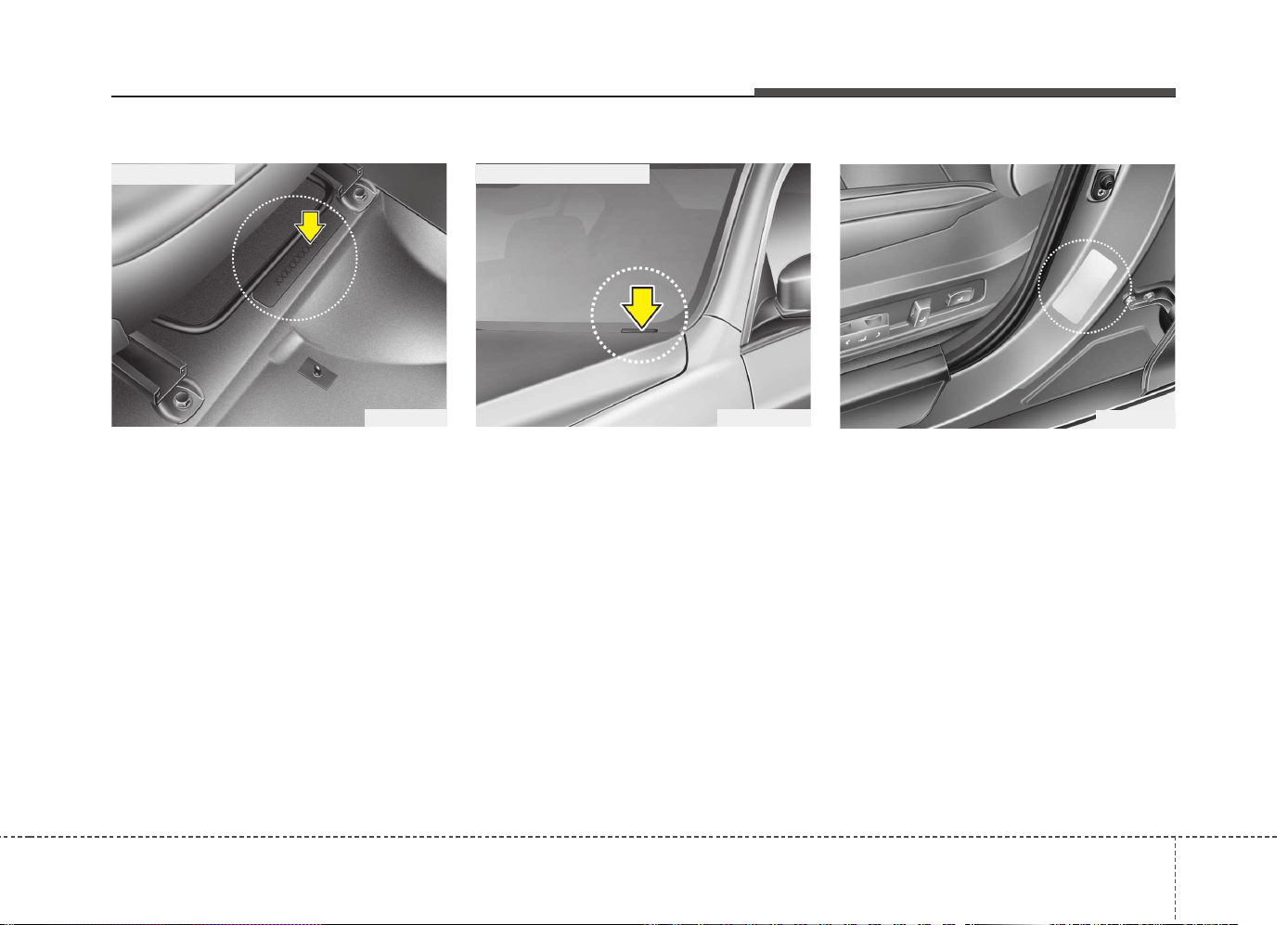
813
Specifications & Consumer information
The vehicle identification number (VIN) is
the number used in registering your vehi-
cle and in all legal matters pertaining to
its ownership, etc.
The number is punched on the floor
under the passenger seat. To check the
number, open the cover.
The VIN is also on a plate attached to the
top of the dashboard. The number on the
plate can easily be seen through the
windshield from outside.
The vehicle certification label attached
on the driver’s (or front passenger’s) side
center pillar gives the vehicle identifica-
tion number (VIN).
VEHICLE IDENTIFICATION NUMBER (VIN)
OJD082002
■ Frame number
VEHICLE CERTIFICATION
LABEL
OBH088005N
■ VIN label (if equipped)
OJD082003
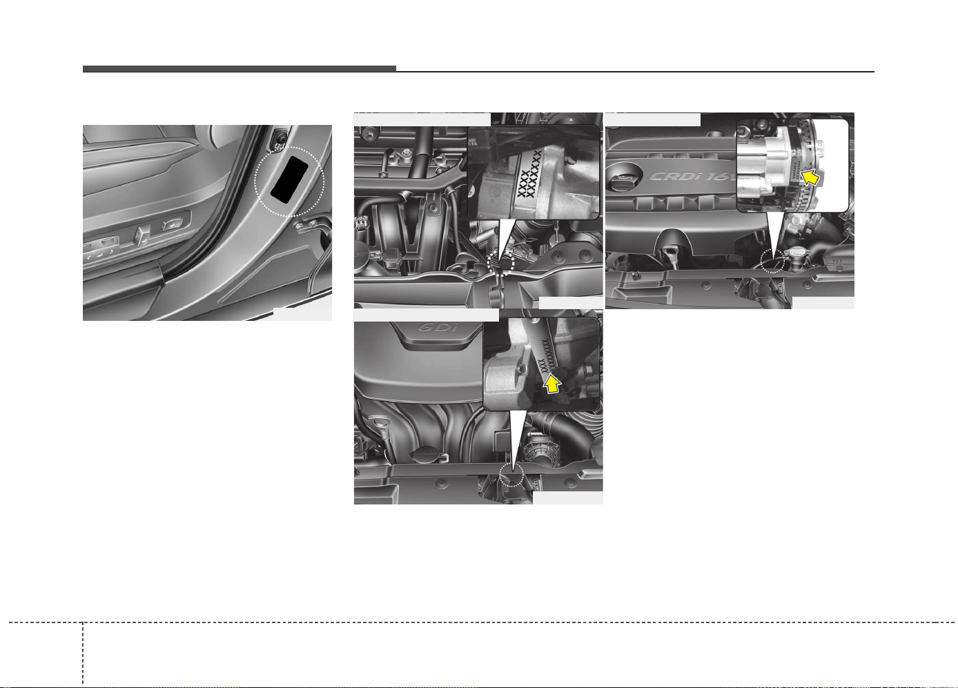
Specifications & Consumer information
148
The tires supplied on your new vehicle
are chosen to provide the best perform-
ance for normal driving.
The tire label located on the driver's side
center pillar gives the tire pressures rec-
ommended for your vehicle.
TIRE SPECIFICATION AND
PRESSURE LABEL
ENGINE NUMBER
OJD082005
■ Gasoline engine (Kappa)
■ Gasoline engine (Gamma)
OTA080004L
■ Diesel engine
OGD081005
OGDE081006
The engine number is stamped on the
engine block as shown in the drawing.
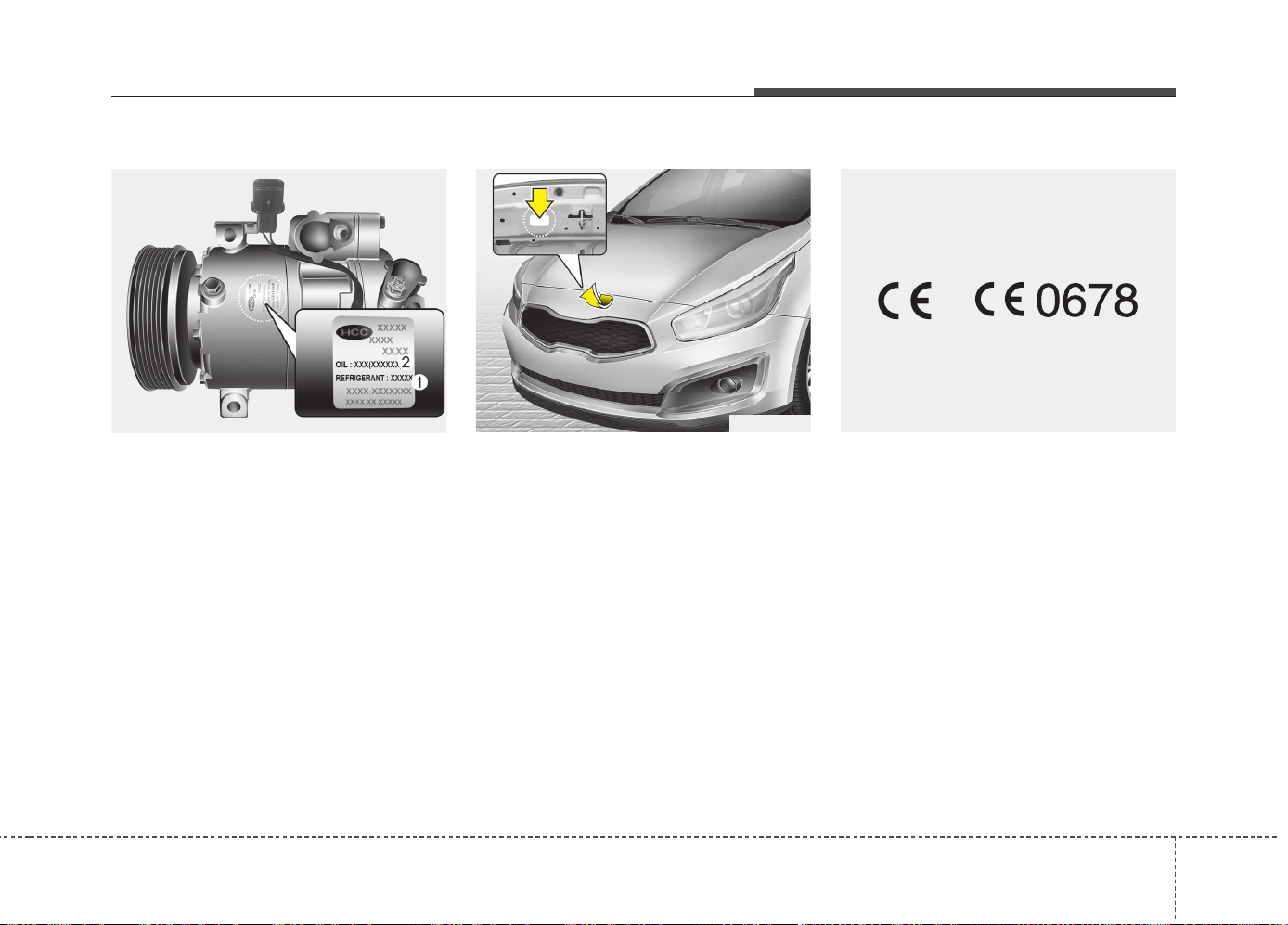
815
Specifications & Consumer information
A compressor label informs you the type
of compressor your vehicle is equipped
with such as model, supplier part num-
ber, production number, refrigerant (1)
and refrigerant oil (2).
The refrigerant label is located on the
underside of the hood.
The radio frequency components of the
vehicle comply with requirements and
other relevant provisions of Directive
1995/5/EC.
Further information including the manu-
facturer's declaration of conformity is
available on Kia web site as follows;
http://www.kia-hotline.com
DECLARATION OF
CONFORMITY
REFRIGERANT LABEL
AIR CONDITIONER
COMPRESSOR LABEL
OHC081001
OJD085001
CE0678
■ Example

Index
I
I

Index
2
I
Active ECO system ......................................................5-39
Active ECO operation ................................................5-39
Limitation of Active ECO operation ..........................5-39
When Active ECO is activated ..................................5-39
Air bag - supplemental restraint system........................3-43
Additional safety precautions ....................................3-65
Air bag warning and indicator ....................................3-46
Air bag warning label ................................................3-66
Curtain air bag ............................................................3-57
Driver's and passenger's front air bag ........................3-51
How does the air bag system operate ........................3-44
Side impact air bag ....................................................3-56
SRS Care ....................................................................3-64
SRS components and functions ..................................3-48
Air cleaner ....................................................................7-35
Filter replacement ......................................................7-35
Air conditioner compressor label ..................................8-15
Air conditioning system ..................................................8-4
Appearance care ..........................................................7-100
Exterior care..............................................................7-100
Interior care ..............................................................7-105
Audio System ..............................................................4-185
Antenna ....................................................................4-185
AUX, USB and iPod
®
port ......................................4-187
Steering wheel audio controls ..................................4-186
Automatic climate control system ..............................4-149
Automatic heating and air conditioning ..................4-150
Checking the amount of air conditioner refrigerant and
compressor lubricant ..............................................4-160
Climate control air filter ..........................................4-157
Manual heating and air conditioning ........................4-152
System operation ......................................................4-157
Automatic transaxle ......................................................5-23
Automatic transaxle operation ....................................5-23
Good driving practices................................................5-28
Battery............................................................................7-42
Battery capacity label..................................................7-43
Battery recharging ......................................................7-43
For best battery service ..............................................7-42
Reset items..................................................................7-44
Before driving..................................................................5-4
Before entering vehicle ................................................5-4
Before starting ..............................................................5-4
Necessary inspections ..................................................5-4
Blind Spot Detection system (BSD)..............................5-74
BSD (Blind Spot Detection)/
LCA (Lane Change Assist) ......................................5-74
Driver’s Attention ......................................................5-80
RCTA (Rear cross traffic alert) ..................................5-78
A
B

I
3
Index
Brake system..................................................................5-40
Anti-lock brake system (ABS)....................................5-48
Electric parking brake (EPB)......................................5-44
Electronic stability control (ESC) ..............................5-51
Emergency Stop Signal (ESS) ....................................5-56
Good braking practices ..............................................5-56
Hill-start assist control (HAC)....................................5-55
Parking brake - Hand type ..........................................5-42
Power brakes ..............................................................5-40
Vehicle stability management (VSM) ........................5-54
Brake/clutch fluid ..........................................................7-32
Checking the brake fluid level....................................7-32
Bulb wattage ....................................................................8-6
Child restraint system ....................................................3-32
Using a child restraint system ....................................3-34
Clean air ......................................................................4-163
Climate control air filter ................................................7-37
Filter inspection ..........................................................7-37
Filter replacement ......................................................7-37
Cruise Control system ..................................................5-58
Declaration of conformity ............................................8-15
Defroster ......................................................................4-139
Rear window defroster..............................................4-139
Dimensions ......................................................................8-2
Door locks......................................................................4-17
Child-protector rear door lock ....................................4-21
Deadlocks....................................................................4-20
Door lock/unlock features ..........................................4-20
From inside ................................................................4-18
From outside ..............................................................4-17
Dual Clutch Transmission (DCT)..................................5-30
Dual clutch transmission operation ............................5-30
Good driving practices................................................5-37
Economical operation ....................................................5-81
Emergency commodity..................................................6-40
Fire extinguisher ........................................................6-40
First aid kit..................................................................6-40
Tire pressure gauge ....................................................6-40
Triangle reflector ........................................................6-40
Emergency starting ..........................................................6-5
Jump starting ................................................................6-5
Push-starting ................................................................6-7
Emission control system..............................................7-107
Engine ..............................................................................8-3
Engine compartment ................................................2-6, 7-3
C
D
E

Index
4
I
Engine coolant ..............................................................7-29
Changing the coolant ..................................................7-31
Checking the coolant level..........................................7-29
Engine number ..............................................................8-14
Engine oil ......................................................................7-27
Changing the engine oil and filter ..............................7-28
Checking the engine oil level ....................................7-27
Engine start/stop button ..................................................5-9
Engine start/stop button position ..................................5-9
Illuminated engine start/stop button ............................5-9
Starting the engine ......................................................5-12
Explanation of scheduled maintenance items ..............7-24
Exterior features ..........................................................4-182
Mounting bracket for roof carrier ............................4-182
Roof rack ..................................................................4-183
Exterior overview (Front)................................................2-2
Exterior overview (Rear) ................................................2-3
Fuel filler lid ..................................................................4-31
Closing the fuel filler lid ............................................4-31
Opening the fuel filler lid ..........................................4-31
Fuel filter (for Diesel)....................................................7-34
Draining water from fuel filter ..................................7-34
Fuel requirements ............................................................1-2
Diesel engine ................................................................1-4
Gasoline engine ............................................................1-2
Fuses ..............................................................................7-56
Fuse/relay panel description ......................................7-61
Gross vehicle weight ......................................................8-5
Hazard warning flasher................................................4-120
Hood ..............................................................................4-29
Closing the hood ........................................................4-30
Opening the hood........................................................4-29
How to use this manual ..................................................1-2
If the engine overheats ....................................................6-8
If the engine will not start ..............................................6-4
If engine doesn’t turn over or turns over slowly ..........6-4
If engine turns over normally but does not start ..........6-4
If you have a flat tire (with spare tire) ............................6-9
Changing tires ............................................................6-10
EC Declaration of Conformity for Jack......................6-18
Jack and tools................................................................6-9
Jack label ....................................................................6-17
Removing and storing the spare tire ..........................6-10
Wheel nut tightening torque ......................................6-14
F
G
H
I

I
5
Index
If you have a flat tire (with Tire Mobility Kit)..............6-19
For 15, 16 inch tire ....................................................6-19
For 17, 18 inch tire ....................................................6-27
In case of an emergency while driving............................6-3
If engine stalls while driving ........................................6-3
If the engine stalls at a crossroad or crossing ..............6-3
If you have a flat tire while driving..............................6-3
Instrument cluster (Normal vision) ..............................4-48
Automatic transaxle shift position indicator ..............4-51
Dual clutch transmission shift indicator ....................4-52
Gauges ........................................................................4-49
Instrument panel illumination ....................................4-49
Manual transaxle shift indicator ................................4-51
Odometer ....................................................................4-53
Speed limiter indicator................................................4-53
Trip computer..............................................................4-53
Instrument cluster (Super vision) ..................................4-61
Automatic transaxle shift position indicator ..............4-67
Dual clutch transmission shift indicator ....................4-67
Gauges ........................................................................4-63
Instrument panel illumination ....................................4-63
LCD display information............................................4-76
Manual transaxle shift indicator ................................4-66
Odometer ....................................................................4-68
Speed limiter indicator................................................4-68
Trip computer..............................................................4-69
Warnings and indicators..............................................4-82
Instrument panel overview ..............................................2-5
Interior features............................................................4-168
Ashtray......................................................................4-168
Aux, USB and iPod ..................................................4-173
Barrier net ................................................................4-176
Bottle holder ............................................................4-170
Cargo area cover ......................................................4-175
Cargo security screen................................................4-178
Cigarette lighter ........................................................4-168
Clothes hanger ..........................................................4-173
Cup holder ................................................................4-169
Floor mat anchor(s) ..................................................4-174
Luggage net (holder) ................................................4-175
Luggage rail system..................................................4-180
Power outlet ..............................................................4-172
Shopping bag holder ................................................4-181
Sunvisor ....................................................................4-171
Interior light ................................................................4-135
Glove box lamp ........................................................4-137
Interior lamp AUTO cut............................................4-135
Luggage room lamp..................................................4-137
Map lamp ..................................................................4-135
Room lamp................................................................4-136
Vanity mirror lamp....................................................4-136
Interior overview ............................................................2-4
ISG (Idle Stop and Go) system......................................5-15
Auto Start....................................................................5-17
Auto stop ....................................................................5-15
Condition of ISG system operation ............................5-18

Index
6
I
ISG system deactivation ............................................5-18
ISG system malfunction ............................................5-19
Key positions ..................................................................5-5
Ignition switch position ................................................5-6
Illuminated ignition switch ..........................................5-5
Starting the engine ........................................................5-7
Keys ................................................................................4-4
Immobilizer system ......................................................4-4
Key operations ..............................................................4-4
Record your key number ..............................................4-4
Lane departure warning system (LDWS)......................5-66
LCD display warnings and indicators
(Instrument panel display) ..........................................4-93
Light bulbs ....................................................................7-79
Front light replacement ..............................................7-80
Headlight and front fog light aiming (for Europe) ....7-85
High mounted stop light bulb replacement ................7-98
Interior light bulb replacement ..................................7-99
License plate light bulb replacement ..........................7-98
Rear combination light bulb replacement ..................7-93
Side repeater light bulb replacement ..........................7-93
Lighting........................................................................4-121
Adaptive Front Lighting System (AFLS) ................4-129
Battery saver function ..............................................4-121
Daytime running light ..............................................4-128
Front fog light ..........................................................4-127
Headlamp delay function..........................................4-121
Headlight (Headlamp) welcome function ................4-121
Headlight leveling device ........................................4-128
High - beam operation ..............................................4-124
High beam assist (HBA) ..........................................4-125
Lighting control ........................................................4-122
Rear fog light ............................................................4-128
Static bending light ..................................................4-122
Turn signals and lane change signals ......................4-126
Luggage volume ..............................................................8-5
Maintenance services ......................................................7-7
Engine compartment precautions (Diesel engine)........7-8
Owner maintenance precautions ..................................7-7
Owner’s responsibility..................................................7-7
Manual climate control system....................................4-140
Checking the amount of air conditioner refrigerant and
compressor lubricant ..............................................4-148
Climate control air filter ..........................................4-147
Heating and air conditioning ....................................4-141
System operation ......................................................4-145
K
L
M

I
7
Index
Manual Transaxle ..........................................................5-20
Good driving practices................................................5-22
Manual transaxle operation ........................................5-20
Mirrors ..........................................................................4-44
Inside rearview mirror ................................................4-44
Outside rearview mirror..............................................4-45
Owner maintenance ........................................................7-9
Owner maintenance schedule ......................................7-9
Panorama sunroof ..........................................................4-34
Closing the sunroof ....................................................4-36
Resetting the sunroof ..................................................4-37
Sliding the sunroof......................................................4-35
Sunroof open warning ................................................4-35
Sunshade ....................................................................4-35
Tilting the sunroof ......................................................4-36
Parking assist system ....................................................4-99
Non-operational conditions ......................................4-102
Operation ..................................................................4-100
Self-diagnosis............................................................4-103
Parking brake - hand type..............................................7-33
Checking the parking brake ........................................7-33
Rear parking assist system ............................................4-95
Non-operational conditions ........................................4-97
Operation ....................................................................4-95
Precautions..................................................................4-97
Self-diagnosis..............................................................4-98
Rearview camera ........................................................4-120
Recommended lubricants and capacities ........................8-9
Recommended SAE viscosity number ......................8-12
Refrigerant label ............................................................8-15
Remote keyless entry ......................................................4-6
Battery replacement ......................................................4-9
Remote keyless entry system operations ......................4-6
Transmitter precautions ................................................4-8
Road warning ..................................................................6-2
Hazard warning flasher ................................................6-2
Scheduled maintenance service ....................................7-11
Maintenance under severe usage conditions
- except Europe (Including Russia) ..........................7-22
Maintenance under severe usage conditions
- for Europe (Except Russia) ....................................7-16
Normal maintenance schedule
- except Europe (Including Russia) ..........................7-18
R
P
O
S

Index
8
I
Normal maintenance schedule
- for Europe (Except Russia) ....................................7-12
Seat ..................................................................................3-2
Driver position memory system....................................3-8
Front seat ......................................................................3-4
Rear seat......................................................................3-14
Seat belts........................................................................3-20
Care of seat belts ........................................................3-31
Pre-tensioner seat belt ................................................3-26
Seat belt precautions ..................................................3-28
Seat belt restraint system ............................................3-20
Smart key ......................................................................4-11
Door lock/unlock in an emergency situation..............4-13
Smart key function......................................................4-11
Smart key precautions ................................................4-13
Smart Parking Assist System (SPAS)..........................4-104
Additional instructions (Messages) ..........................4-118
How the system works (Exit mode) ........................4-115
How the system works (Parking mode)....................4-109
Non-operating condition ..........................................4-106
Operating condition ..................................................4-105
System malfunction ..................................................4-119
Special driving conditions ............................................5-83
Driving at night ..........................................................5-84
Driving in flooded areas ............................................5-85
Driving in the rain ......................................................5-84
Driving off-road..........................................................5-85
Hazardous driving conditions ....................................5-83
Highway driving ........................................................5-85
Rocking the vehicle ....................................................5-83
Smooth cornering........................................................5-84
Speed limit control system ............................................5-63
Speed Limit Information Function (SLIF) ....................5-69
Display ........................................................................5-70
Driver's attention ........................................................5-73
Operation ....................................................................5-70
SLIF activation/deactivation ......................................5-69
Warning message ........................................................5-72
Steering wheel................................................................4-39
Electronic power steering ..........................................4-39
Flex steering wheel ....................................................4-42
Heated steering wheel ................................................4-40
Horn ............................................................................4-41
Tilt and telescopic steering ........................................4-40
Storage compartment ..................................................4-164
Center console storage..............................................4-164
Cool box....................................................................4-165
Glove box..................................................................4-165
Luggage side tray......................................................4-167
Luggage tray ............................................................4-166
Sliding armrest..........................................................4-164
Sunglass holder ........................................................4-166

I
9
Index
Tailgate ..........................................................................4-22
Closing the tailgate ....................................................4-22
Emergency tailgate safety release ..............................4-23
Opening the tailgate....................................................4-22
Theft-alarm system ........................................................4-14
Armed stage ................................................................4-14
Disarmed stage............................................................4-16
Theft-alarm stage ........................................................4-15
Tire Pressure Monitoring System (TPMS)....................6-30
Changing a tire with TPMS ........................................6-33
Tire specification and pressure label ............................8-14
Tires and wheels ....................................................7-45, 8-8
Checking tire inflation pressure..................................7-47
Low aspect ratio tire ..................................................7-55
Recommended cold tire inflation pressures................7-45
Tire care ......................................................................7-45
Tire maintenance ........................................................7-51
Tire replacement ........................................................7-49
Tire rotation ................................................................7-48
Tire sidewall labeling..................................................7-51
Tire traction ................................................................7-51
Wheel alignment and tire balance ..............................7-49
Wheel replacement ....................................................7-51
Towing ..........................................................................6-36
Emergency towing ......................................................6-37
Removable towing hook ............................................6-37
Towing service ............................................................6-36
Trailer Towing ..............................................................5-90
Driving with a trailer ..................................................5-92
Hitches ........................................................................5-91
If you do decide to pull a trailer ................................5-97
Maintenance when trailer towing ..............................5-96
Safety chains ..............................................................5-92
Trailer brakes ..............................................................5-92
Vehicle break-in process..................................................1-5
Vehicle certification label ..............................................8-13
Vehicle identification number (VIN) ............................8-13
Vehicle weight ............................................................5-100
Base curb weight ......................................................5-100
Cargo weight ............................................................5-100
GAW (Gross axle weight) ........................................5-100
GAWR (Gross axle weight rating) ..........................5-100
GVW (Gross vehicle weight) ..................................5-100
GVWR (Gross vehicle weight rating) ......................5-100
Overloading ..............................................................5-100
Vehicle curb weight ..................................................5-100
T
V

Index
10
I
Washer fluid ..................................................................7-33
Checking the washer fluid level ................................7-33
Welcome system ..........................................................4-138
Headlamp welcome ..................................................4-138
Interior light ..............................................................4-138
Puddle lamp ..............................................................4-138
Windows ........................................................................4-24
Manual windows ........................................................4-28
Power windows ..........................................................4-25
Windshield defrosting and defogging..........................4-161
Automatic climate control system ............................4-162
Manual climate control system ................................4-161
Winter driving................................................................5-86
Carry emergency equipment ......................................5-89
Change to “winter weight” oil if necessary................5-88
Check battery and cables ............................................5-88
Check spark plugs and ignition system ......................5-88
Don't let ice and snow accumulate underneath ..........5-89
Don't let your parking brake freeze ............................5-89
Snowy or Icy conditions ............................................5-86
To keep locks from freezing ......................................5-89
Use approved window washer anti-freeze in system ..5-89
Use high quality ethylene glycol coolant ..................5-88
Wiper blades ..................................................................7-39
Blade inspection..........................................................7-39
Blade replacement ......................................................7-39
Wipers and washers ....................................................4-131
Rear window wiper and washer switch ....................4-134
Windshield washers (Front)......................................4-133
Windshield wipers (Front) ........................................4-131
W
