Loading ...
2
Important Safety Information is supplied in a separate document “Important Additional Operation Information Guide
”
Copyright 2020 © by McIntosh Laboratory, Inc.
Inside the Box
Besides all the protective packaging you should nd:
• A literature pack including this manual
• An AC Power Cord
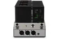
• An MHA200 Headphone Amplier
Taking it out of the Box
The easiest way to remove the MHA200 from its
shipping carton is to:
• Open the top of the box
• Remove and read this manual
• Gently turn the box over with the aps
extended outward
• Lift the box upward to reveal the foam
encased MHA200
• Carefully remove the MHA200 from the
packaging
Where to Put it
Place the MHA200 upright on a sturdy at surface
that can support its weight with adequate open space.
Cool operation ensures the longest possible operating
life for any electronic instrument. Always allow air to
ow through the ventilation holes on the bottom of the
amplier and space for the warm air to escape at the
top.
Allow at least 19 inches (48.3cm) above the top; 4
inches (10.2cm) for the Rear and Sides; allow 1/2 inch
(1.3cm) below the Power Amplier so the airow is
not obstucted. Do not remove the feet.
For dimensions see “Dimensions” on page 6.
DO THIS FIRST
Removal of Foam Inserts over Vacuum
Tubes
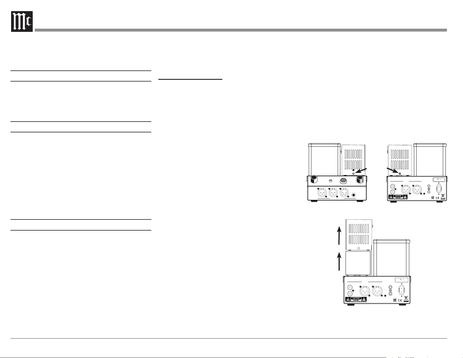
IMPORTANT!
REMOVE THE FOAM INSERTS OVER THE
VACUUM TUBES PRIOR TO CONNECTING
THE A.C. POWER SUPPLY CORD.
• To prevent damage to the Tubes during
shipping, there are special foam inserts
surrounding the Tubes of the Power Amplier
• The Foam Inserts must be removed from
the MHA200 before connecting the AC Power
Supply Cord to the Power Amplier
• Failure to do so has the potential of a
Fire Hazard, resulting in damage to the
MHA200 and the surrounding environment
• Follow these instructions for removal of
the packing foam before connecting the AC
Power Supply Cord to the MHA200
To remove the protective foam, it is necessary to
temporarily remove the two Tube Covers. To remove
each Tube Cover:
• Use a Phillips Head #2 screw driver to remove
the two screws that hold the Tube Cover (see
Figure 01)
• Pull the Tube Cover upward o of the Tube
Cover Retaining Posts (see Figure 02)
• Pull the protective foam straight up o the
Vacuum Tubes (see Figure 02)
• Replace the Tube Cover
• Replace the two screws to secure the cover to
the Tube Cover Retaining Posts (see Figure
01)
Save the protective foam and warning label for
possible future use.
POWER
CONTROL
IN
OUT
L
R
L
R
BALANCEDUNBALANCED
INPUTS
50 WATTS
120V 50 60Hz/
4
ANDBY /
ST ON
1
LOAD RANGE
STER EO
R
HEAD PHONE OUTPUT S
STER EO
L
Screws
Figure 01– Tube cover screws
POWER
CONTROL
IN
OUT
L
R
L
R
BALANCEDUNBALANCED
INPUTS
50 WATTS
120V 50 60Hz/
Figure 02– Lift Tube Cover and foam up
Loading ...
Loading ...
Loading ...