
Integrated Refrigeration Installation Guide
BUILT-IN REFRIGERATION
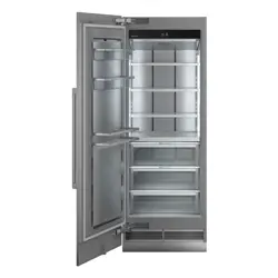
SKSCF1801P
SKSCF2401P
SKSCF3001P
SKSCR2401P
SKSCR3001P
Copyright © 2017 - 2018 Signature Kitchen Suite. All Rights Reserved.
www.signaturekitchensuite.com
MFL67410814_Rev.04
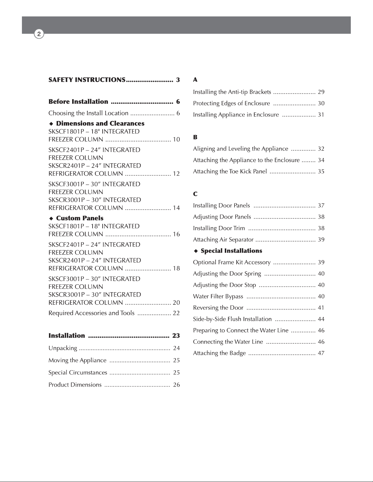
Table of Contents

SAFETY INSTRUCTIONS
WARNING
TIP-OVER HAZARD
Use two or more people to move and install the refrigerator.
To prevent the refrigerator from tipping over, install anti-tip brackets
(provided). Failure to follow the refrigerator installation instructions
can result in serious injury or death.
WARNING
You may be killed or seriously injured if you don’t follow instructions.
WARNING
the product, basic safety precautions should be followed, including the
following. Read all instructions before using this appliance.
CAUTION
Indicates an imminently hazardous situation which, if not avoided, may
result in minor or moderate injury, or product damage.
IMPORTANT SAFETY INSTRUCTIONS
This guide contains many important safety messages.
Always read and obey all safety messages.
This is the safety alert symbol. It alerts you to safety messages that inform you of hazards
that can kill or hurt you or others or cause damage to the product.
All safety messages will be preceded by the safety alert symbol and the hazard signal word
WARNING, or CAUTION. These words mean:
All safety messages will identify the hazard, tell you how to reduce the chance of injury, and
tell you what can happen if the instructions are not followed.
Installation
risk of tipover, personal injury, and product or property damage.
ventilated area.
product malfunction.
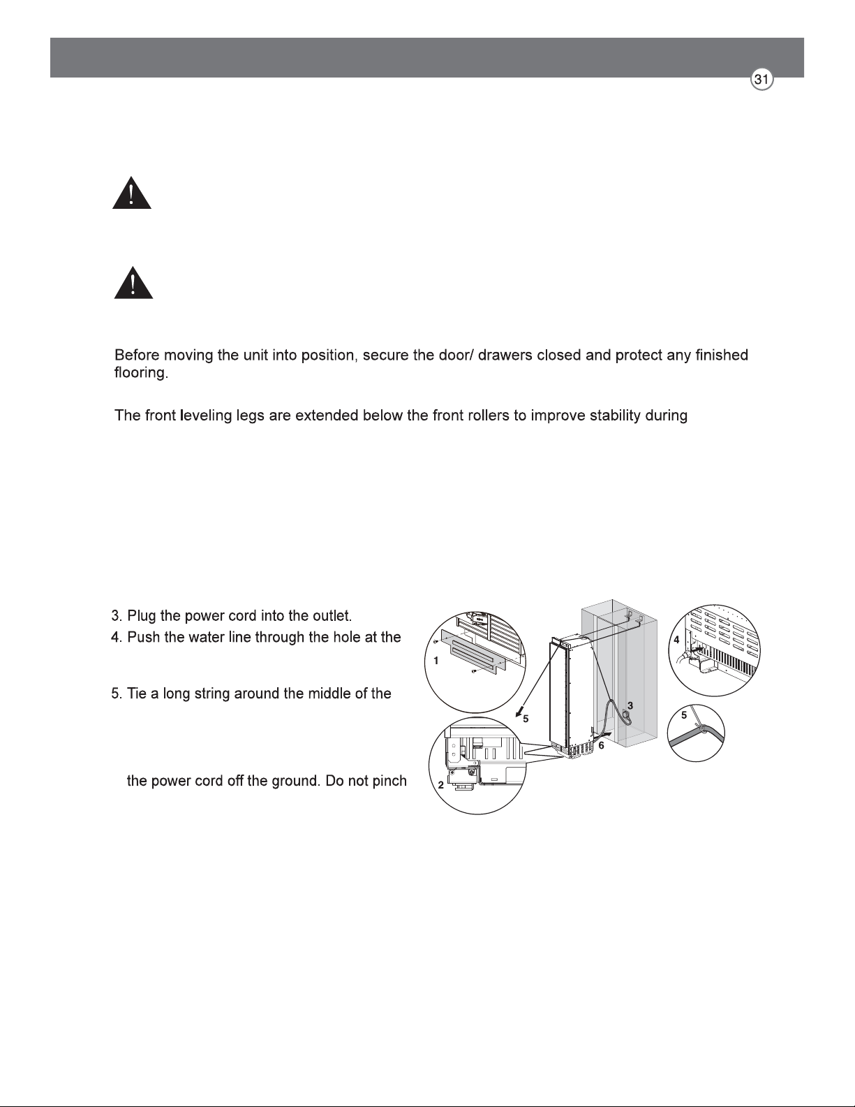
during installation and frequent use.
operation and use without twisting or deforming.
bending. The product must be level both horizontally and vertically.
Electrical Connection
Use a dedicated outlet.
Plug in the power plug with the power cord facing downward.
When installing or moving the refrigerator, be careful not to roll over or damage the
power cord. Do not squeeze or crush the cord or plug when pushing the refrigerator in.
Do not allow the power cord to be bent, crushed, or damaged. Do not run the power
Do not extend or modify the length of the power cord.
Turn off the power before cleaning or moving the refrigerator.
Do not pull out the cord or touch the power plug with wet hands.
Remove water or dust from the power plug and insert it securely into the wall socket.
Do not unplug the refrigerator by pulling on the cord.
Do not use the power cord or the power plug if it is damaged or if the outlet is damaged.
Wait for 5 minutes or longer when reconnecting the plug or turning the power back on.
Give the compressor time to cycle before restarting.
General
electrical power and grounding must comply with local codes and ordinances and be made by
licensed personnel when required. In the absence of a local code:
Appliance is very heavy:
CAUTION
Do not remove the cover of the automatic ice dispenser.
The internal mechanism of the icemaker can cause injury if handled.
Do not stick your hands under the refrigerator.
Sharp edges, fans, and wires may cause an injury
Save these instructions for the local inspector's use.
Observe all governing codes and ordinances.
Installer: Leave these instructions with the consumer.
Consumer: Keep these instructions with the owner's manual for future reference.
If the supply cord is damaged, it must be replaced by the manufacturer or its service
Before Installation
Choosing the Install Location
Anti-tip Devices
WARNING
Temperature and Humidity
The appliance should be installed in a dry, well ventilated area.
-
tions.
oven or radiator.
WARNING: Tip Hazard
securely installed.
installing the appliance in a stable position is to use the supplied anti-tip devices.
If the enclosure is sturdy enough, attaching the appliance to the upper and side walls of the enclo-
If in doubt, contact an architect or structural engineer.
Enclosure
Floor
-
nals of the opening to make sure corners are square.
cabinets. Make sure the enclosure or the adjacent cabinets are securely connected to the
WARNING
-
mance.
-
Electrical Requirements
WARNING
The receptacle must be installed by a licensed electrician only.
Grounding
This appliance must be grounded. In the event of a malfunction or breakdown, grounding will
reduce the risk of electric shock by providing a path of least resistance for the electric current.
WARNING: Improper connection of the equipment grounding conductor may result in electric
if you are in doubt as to whether the appliance has been properly grounded.
NOTE
Some local regulations may require a separate ground. In such cases, the required ground
wire, clamp and screw are available as a separate accessory and must be purchased sepa-
rately.
Never ground the appliance to plastic plumbing lines, gas lines or water pipes.
Water Connection
CAUTION
-
ily accessible.
-

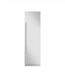
SKSCF1801P – 18" INTEGRATED FREEZER COLUMN
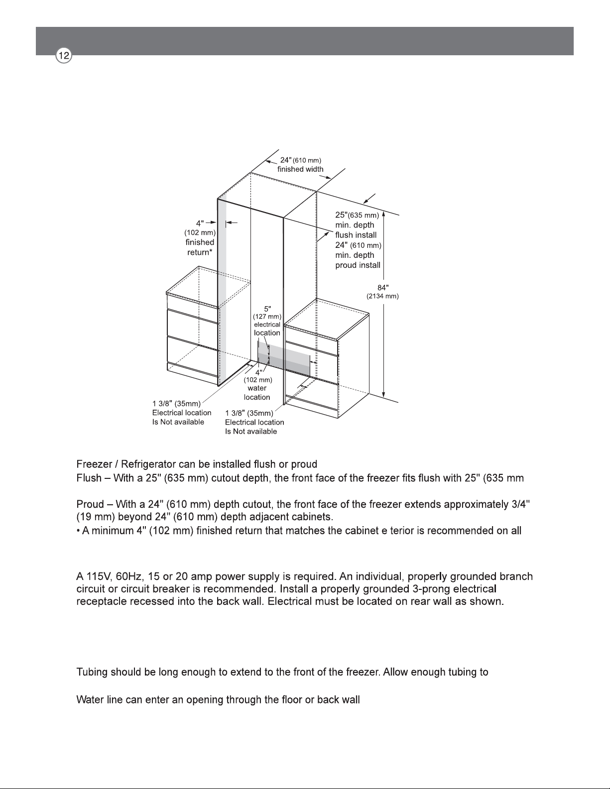
NOTE
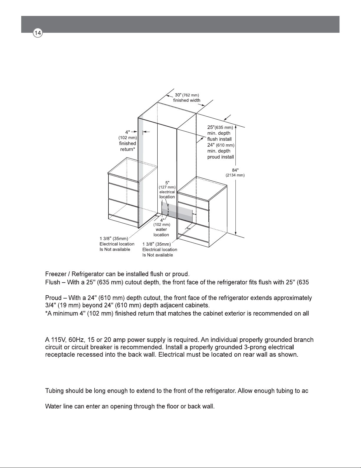
depth adjacent cabinets.
sides and the top of the cutout opening. The shaded area will be visible after installation.
ELECTRICAL
Note: GFI (ground fault interrupter) is not recommended.
WATER LINE
A cold water supply is required for automatic icemaker operation.
The water pressure must be between 20 and 120 psi.
-
date a bend leading into the water line connection.
Install a shut-off valve between the icemaker water valve and the cold water supply in the home.
CUTOUT DIMENSIONS – FLUSH OR PROUD INSTALLATION, SINGLE COLUMN
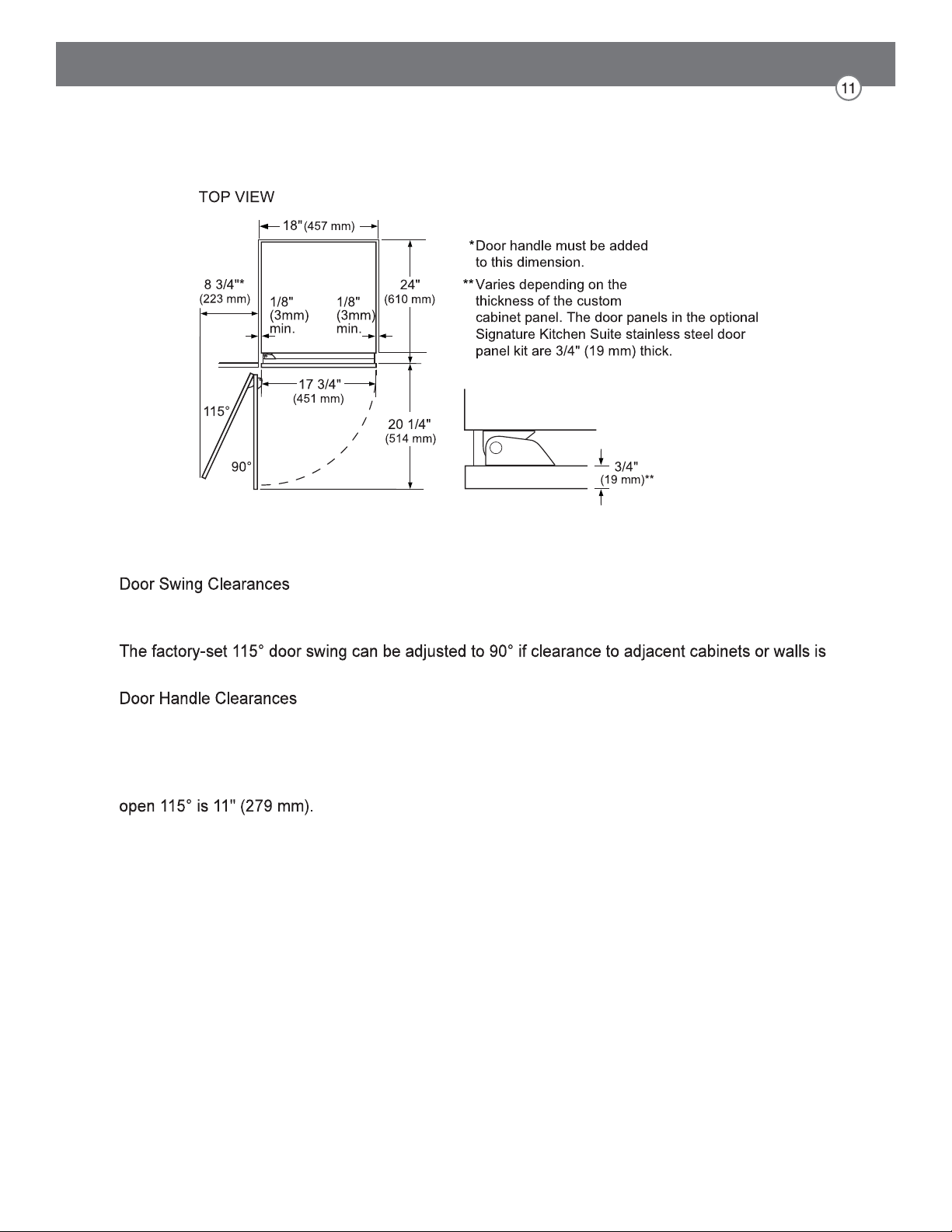
NOTE
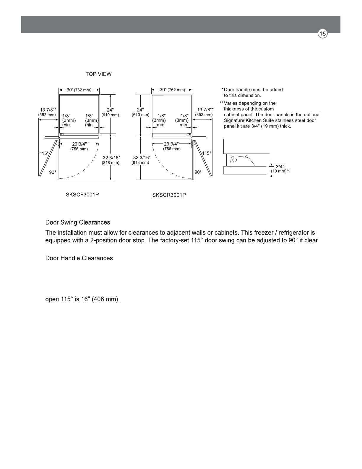
The installation must allow for clearances to adjacent walls or cabinets. This freezer is equipped with
a 2-position door stop.
restricted.
The door handle depth must be added to the dimension where noted to determine the total
clearance required from adjacent cabinets or walls. This clearance will vary depending on the custom
handle used. When using Signature Kitchen Suite handles or the Signature Kitchen Suite stainless
steel door panel kit with handles (optional accessories), the door handle clearance with the door
INSTALLATION CLEARANCES
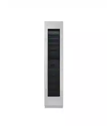
SKSCF2401P – 24" INTEGRATED FREEZER COLUMN
SKSCR2401P – 24" INTEGRATED REFRIGERATOR COLUMN
NOTE
depth adjacent cabinets.
sides and the top of the cutout opening. The shaded area will be visible after installation.
ELECTRICAL
Note: GFI (ground fault interrupter) is not recommended.
WATER LINE
A cold water supply is required for automatic icemaker operation.
The water pressure must be between 20 and 120 psi.
accommodate a bend leading into the water line connection.
Install a shut-off valve between the icemaker water valve and the cold water supply in the home.
CUTOUT DIMENSIONS – FLUSH OR PROUD INSTALLATION, SINGLE COLUMN

NOTE
equipped with 2-position door stops.
restricted.
The door handle depth must be added to the dimension where noted to determine the total clearance
required from adjacent cabinets or walls. This clearance will vary depending on the custom handle
used. When using Signature Kitchen Suite handles or the Signature Kitchen Suite stainless steel
door panel kit with handles (optional accessories), the door handle clearance with the door open
INSTALLATION CLEARANCES
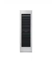
SKSCF3001P – 30" INTEGRATED FREEZER COLUMN
SKSCR3001P – 30" INTEGRATED REFRIGERATOR COLUMN
NOTE
mm) depth adjacent cabinets.
sides and the top of the cutout opening. The shaded area will be visible after installation.
ELECTRICAL
Note: GFI (ground fault interrupter) is not recommended.
WATER LINE
The water pressure must be between 20 and 120 psi.
-
commodate a bend leading into the water line connection.
Install a shut-off valve between the water valve and cold water supply in the home.
CUTOUT DIMENSIONS – FLUSH OR PROUD INSTALLATION, SINGLE COLUMN
NOTE
-
ance to adjacent cabinets or walls is restricted.
The door handle depth must be added to the dimension where noted to determine the total clear-
ances required from adjacent cabinets or walls. This clearance will vary depending on the custom
handle used. When using Signature Kitchen Suite handles or the Signature Kitchen Suite stainless
steel door panel kit with handles (optional accessories), the door handle clearance with the door
INSTALLATION CLEARANCES
SKSCF1801P – 18" INTEGRATED FREEZER COLUMN
NOTES
custom door panels are required.
For custom panels: Use templates provided with units to pre-drill holes for mounting panel brackets
(provided with unit). Adjustment screws and instructions also provided with units.
DESIGN TIPS
the optional frame kit may be used.
If using custom panels, a custom toe kick is required.
Custom handles are required for installation. Brushed aluminum handles are available as an optional
accessory.
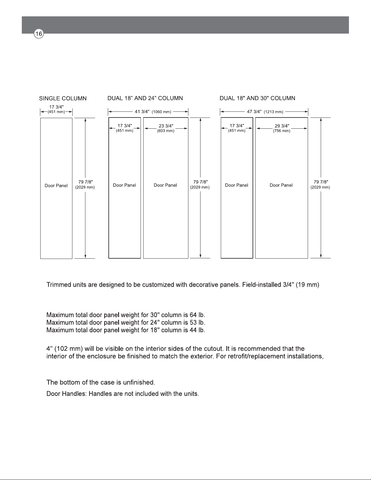
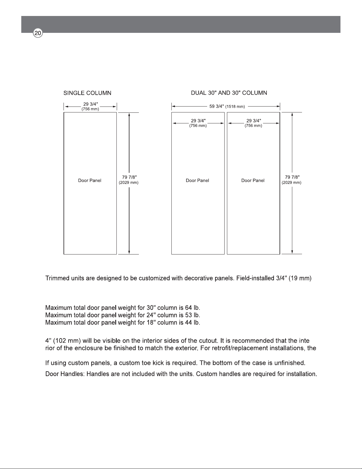
3/4" (19 MM) CUSTOM PANEL DIMENSIONS – FLUSH INSTALLATION
COLUMN
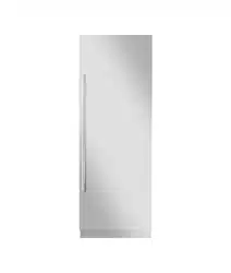
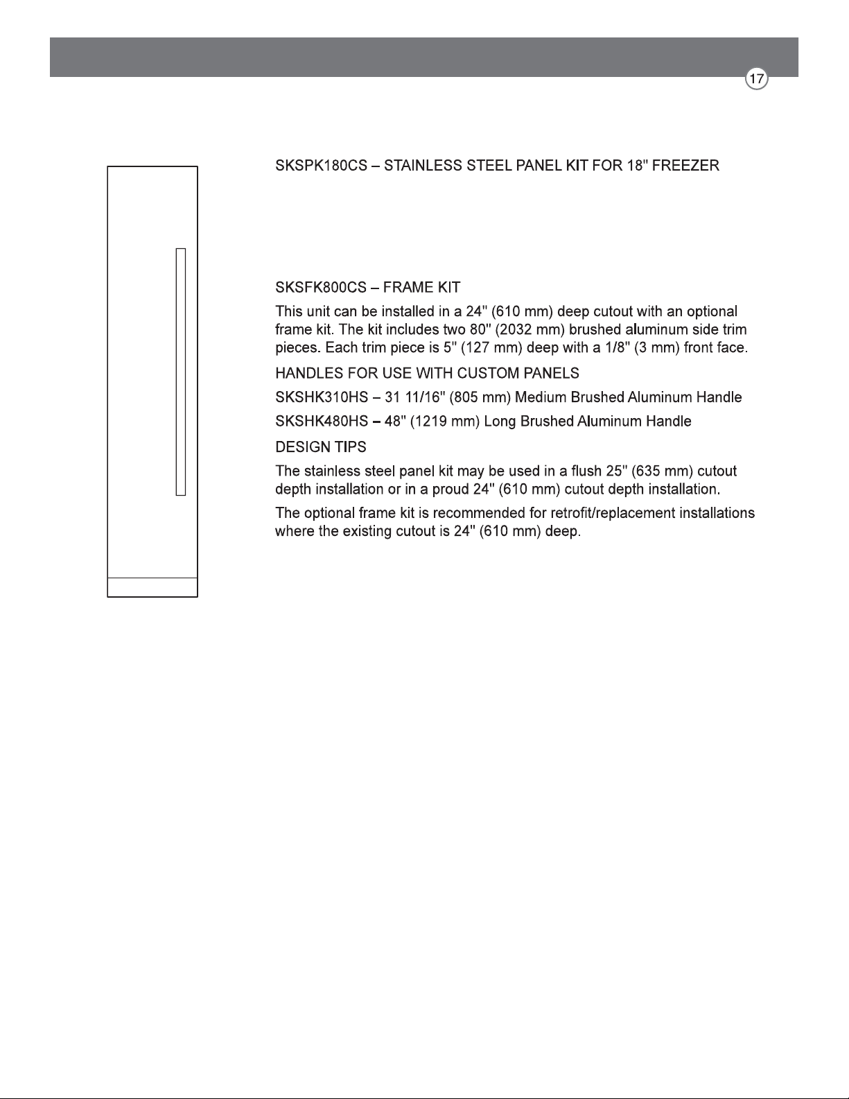
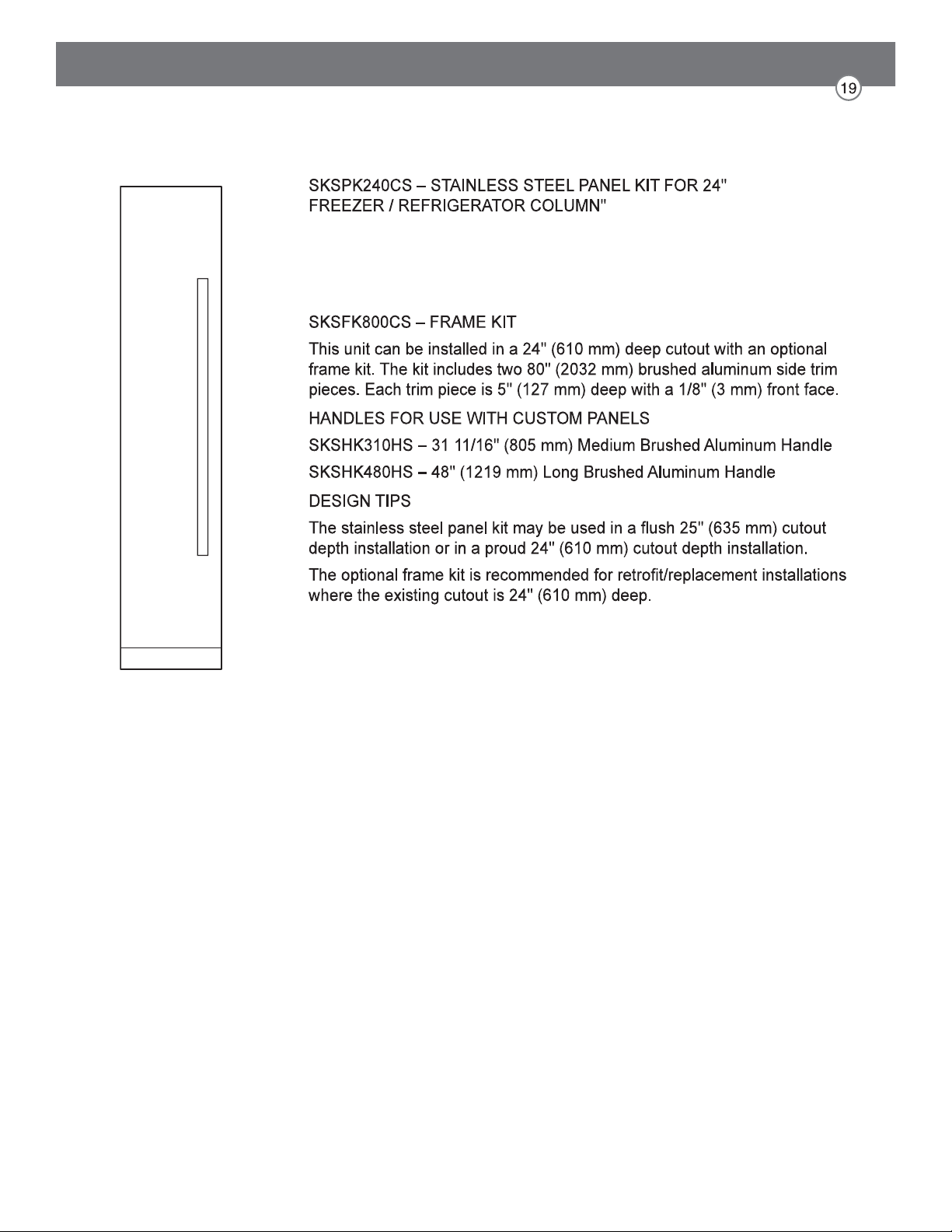
This unit can be installed with an optional stainless steel panel kit. The kit
includes one door panel, one toe kick and one handle. This kit is
reversible and can be used in both right hand and left hand door swing
installations.
OPTIONAL ACCESSORIES – FLUSH OR PROUD INSTALLATION

SKSCF2401P – 24" INTEGRATED FREEZER COLUMN
SKSCR2401P – 24" INTEGRATED REFRIGERATOR COLUMN
NOTES
custom door panels are required.
For custom panels: Use templates provided with units to pre-drill holes for mounting panel brackets
(provided with unit). Adjustment screws and instructions also provided with units.
DESIGN TIPS
the optional frame kit may be used.
If using custom panels, a custom toe kick is required.
Custom handles are required for installation. Brushed aluminum handles are available as an optional
accessory.
3/4" (19 MM) CUSTOM PANEL DIMENSIONS – FLUSH INSTALLATION
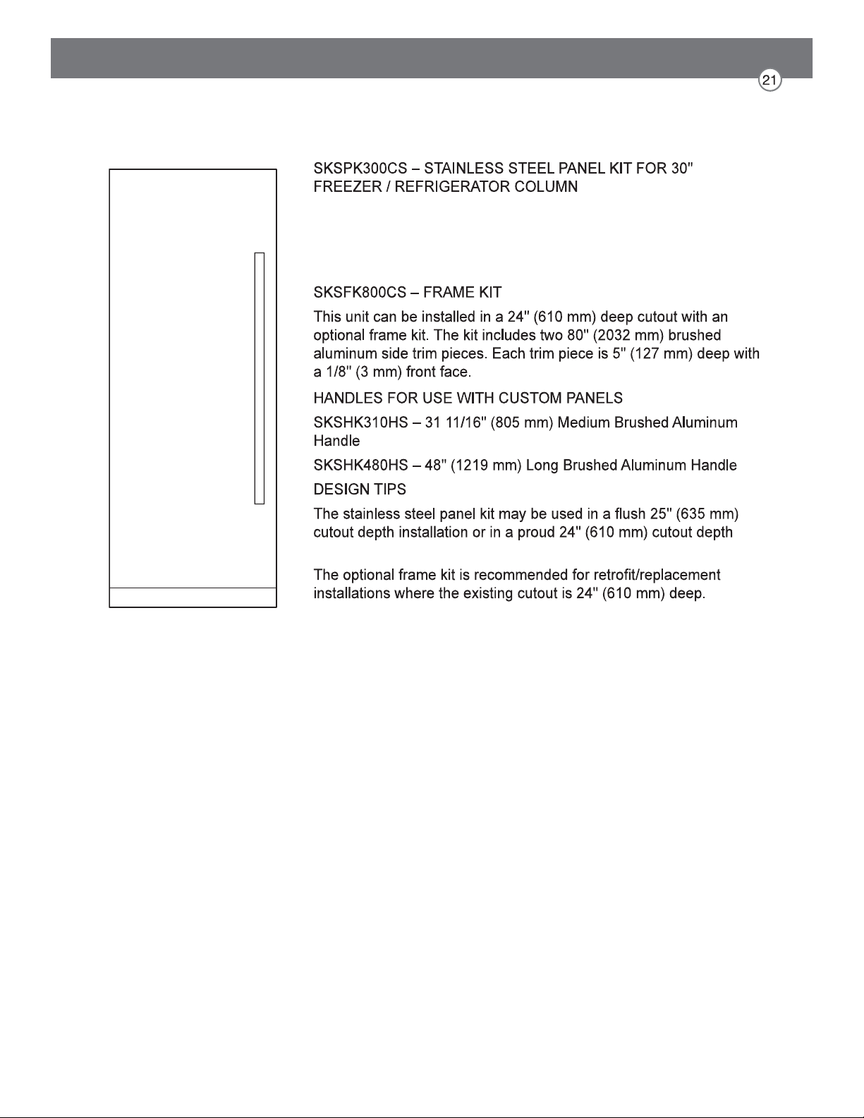
This unit can be installed with an optional stainless steel panel kit. The kit
includes one door panel, one toe kick and one handle. This kit is
reversible and can be used in both right hand and left hand door swing
installations.
OPTIONAL ACCESSORIES – FLUSH OR PROUD INSTALLATION
SKSCF3001P – 30" INTEGRATED FREEZER COLUMN
SKSCR3001P – 30" INTEGRATED REFRIGERATOR COLUMN
NOTES
custom door panels are required.
For custom panels: Use templates provided with units to pre-drill holes for mounting panel brackets
(provided with unit). Adjustment screws and instructions also provided with units.
DESIGN TIPS
-
optional frame kit may be used.
Brushed aluminum handles are available as an optional accessory.
3/4" (19 MM) CUSTOM PANEL DIMENSIONS – FLUSH INSTALLATION
This unit can be installed with an optional stainless steel panel kit.
The kit includes one door panel, one toe kick and one handle. This
kit is reversible and can be used in both right hand and left hand door
swing installations.
installation.
OPTIONAL ACCESSORIES – FLUSH OR PROUD INSTALLATION
Required Accessories and Tools
Supplied Accessories
Installation instructions
Operating instructions
Installation kit
Other
Stepladder
materials
Wood screws in different sizes
Thin plywood sheet, particle board or
Suitable material for covering and protecting
furniture (e.g. protective sheets)
Adhesive tape
Signature Kitchen Suite.
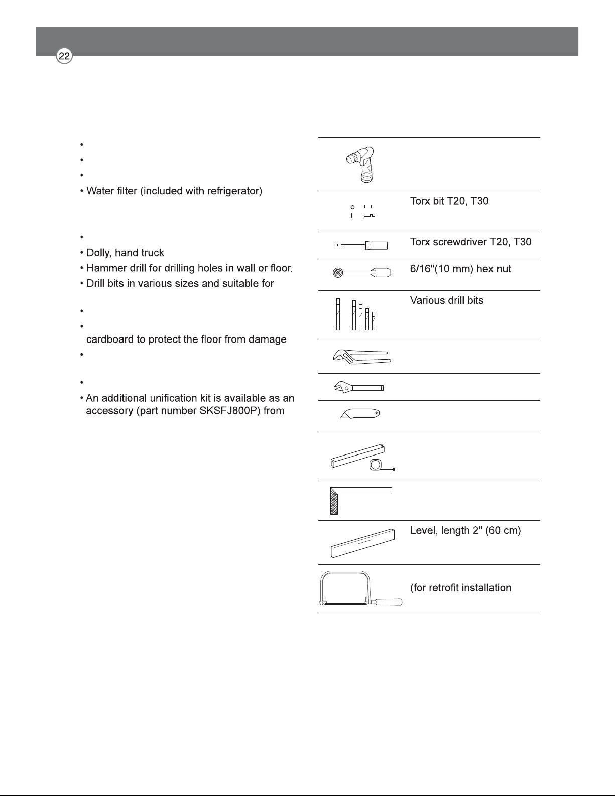
Tools
Cordiess screwdriver
and magnetic holder
driver
Multigrip pliers
Adjustable wrench
Cutter with adustable
blade
Metal tape measure, fold-
ing rule
Square
and 4'(1.2 m)
saw to cut top trim pieces
only)
Installation
The following installation instructions describe the installation steps for various appliance
types:
The diagrams may be a general representation of your appliance.
Unpacking
Check appliance for damage in transit.
If in doubt, contact your dealer.
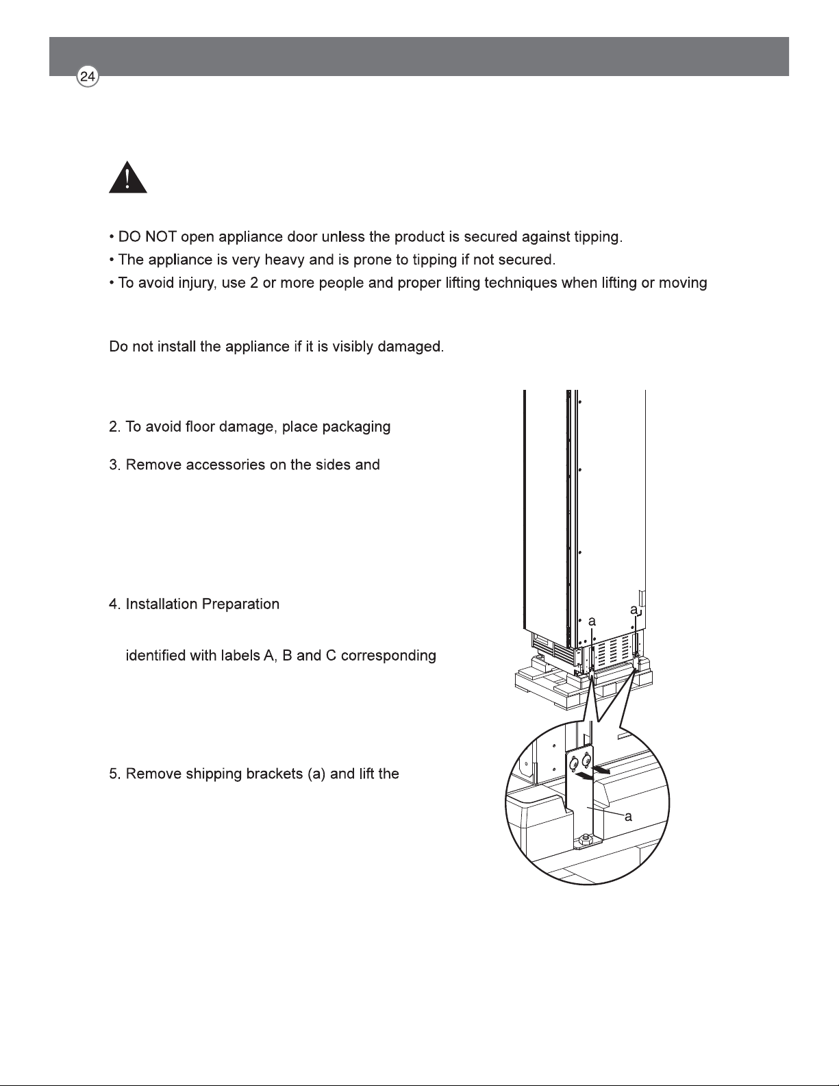
1. Remove the packaging carton, being careful not
to damage the surface of the appliance.
cardboard or plywood under the appliance.
underneath the appliance.
NOTE:
To avoid damaging parts, do not remove the
protective shipping materials inside the appliance
until the installation is complete.
Unpack installation materials and accessories.
To simplify installation, the packages are
to the manual sections.
CAUTION:
Appliance is very heavy. Use two or more people
when lifting or moving the appliance.
appliance off the pallet.
WARNING
To avoid serious injury or product damage:
the appliance.
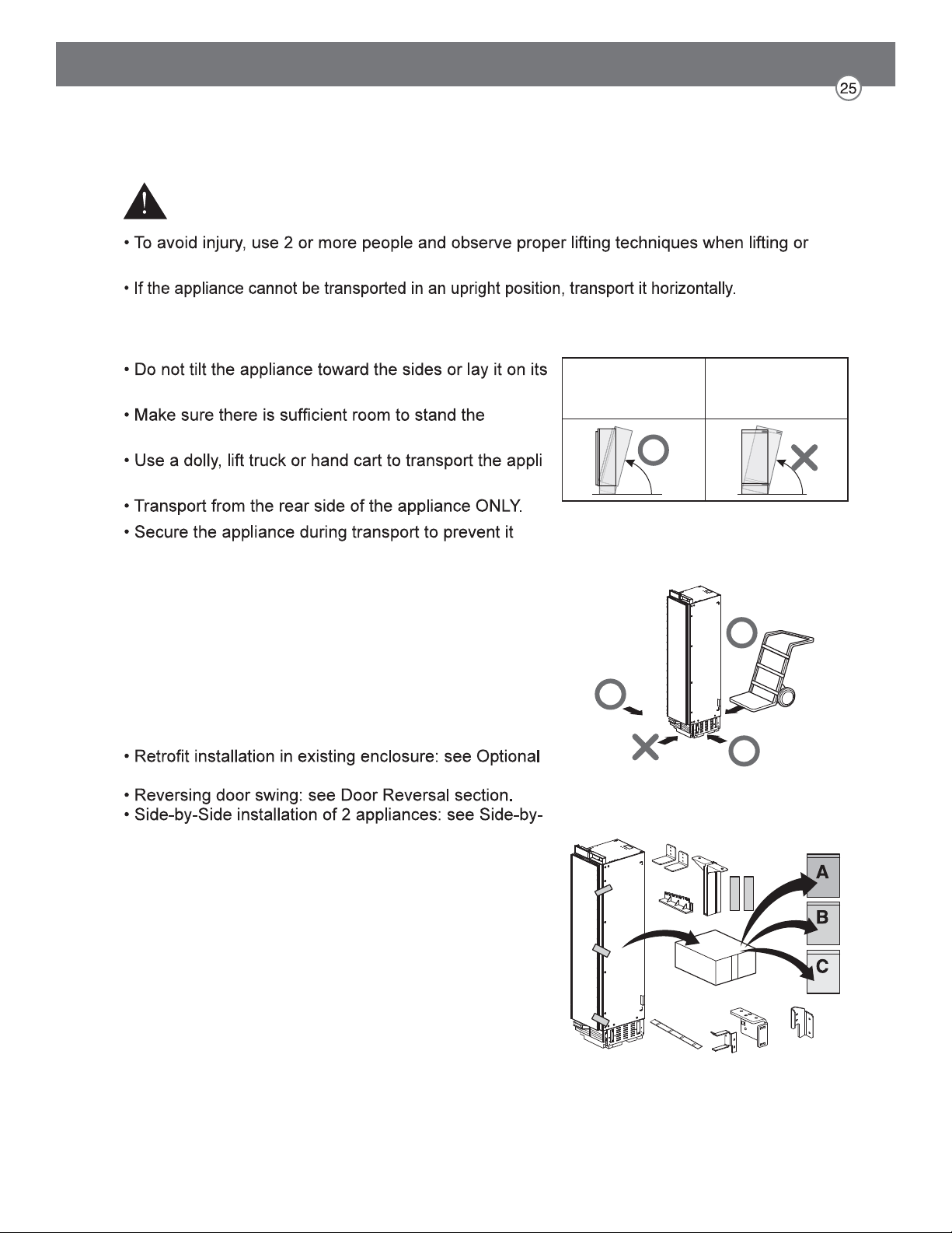
Moving the Appliance
WARNING
moving the appliance.
To avoid product damage:
sides.
appliance upright before doing so.
-
ance.
from tipping.
Special Circumstances
Before proceeding with your installation, check if any of
the following special circumstances apply to your instal-
lation. If so, follow the relevant instructions in the
Special Installations section before continuing the
installation.
Frame Kit Accessory section.
Side Installation section.
Raise up via
appliance rear
Do not raise up
from appliance
side
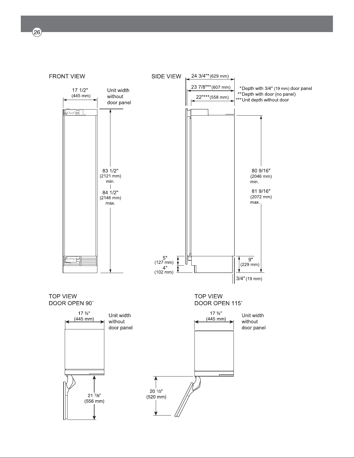
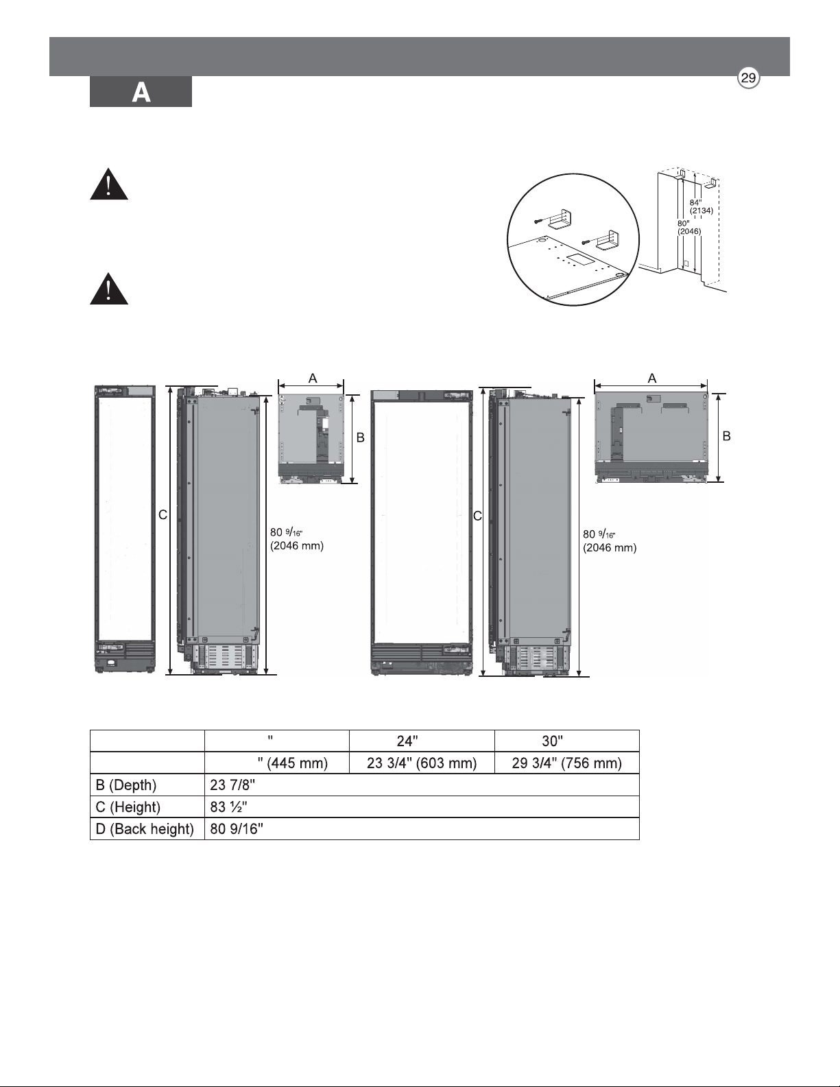
Product Dimensions
18" Freezer Column
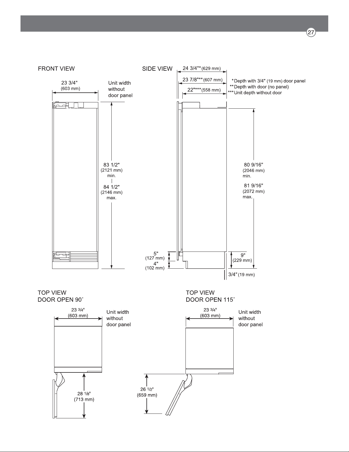
24" Freezer / Refrigerator Column
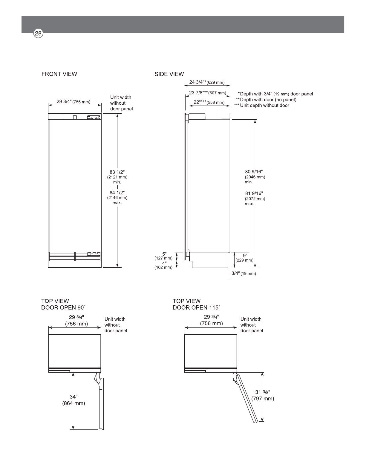
30" Freezer / Refrigerator Column
Installing the Anti-tip Brackets
WARNING
To avoid injury or damage, check for electrical wires or
plumbing in walls before drilling or installing screws.
CAUTION
To avoid injury, observe all safety practices during
installation, including wearing safety glasses and other
safety apparel.
18 Unit Unit Unit
A (Width) 17 ½
(607 mm)
(2121 mm)
(2046 mm)
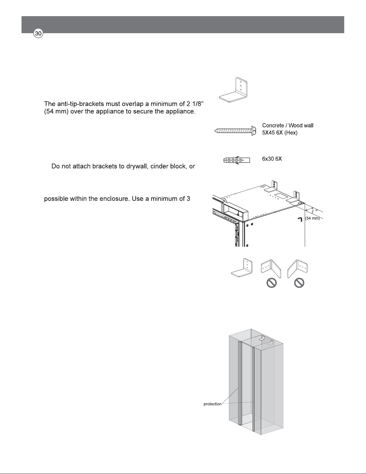
NOTE:
2 anti-tip-brackets are required for each appliance.
1. Install the anti-tip brackets at the rear of the enclosure,
locating the brackets based on stud locations and
product and enclosure dimensions.
2. Make sure the anti-tip brackets are securely attached
to a stud or other weight-bearing structure.
uncured concrete.
To ensure safety, at least one bracket must be
attached to a stud. Attach brackets to studs wherever
screws or bolts to attach each bracket.
Anti-tip brackets (2)
>2
1
8
Protecting Edges of Enclosure
To protect the front edges of the enclosure, tape thin
cardboard or some other protective material around the
edges.
Brackets must be attached as shown at right. The brackets
could fail to prevent tipover of the unit if installed in an
alternate orientation.
Installing Appliance in Enclosure
1. Remove the base panel.
2. Retract the leveling legs so the appliance
can be wheeled forward.
rear of the appliance until it emerges from
the hole at the front of the appliance.
power cord. Feed the string over the top of
the appliance, pull it until the power cord
is held high off the ground, then tape the
string to the front of the appliance to hold
or strain the power cord. Make sure it is still
plugged in.
6. Carefully move the appliance into the
enclosure, making sure not to pinch the
power cord or water line under or behind the
appliance.
7. Remove the edge protection on the
enclosure.
CAUTION
Take care to avoid damaging the water line or power cord when moving the appliance into the
enclosure.
Use an appliance dolly to move the unit near the opening.
placement. Once the unit is placed in front of the opening, completely retract the front leveling
legs to allow the unit to be rolled into position. Front and rear leveling legs can be adjusted
from the front once the unit is positioned.
If the unit has been on its back or side, it must stand upright for a minimum of 24 hours before
turning on the power.
After the appliance is rolled into position, verify that the anti-tip brackets are properly engaged.
WARNING
Use 2 or more people when installing the appliance. Take care when moving the appliance. It
is very heavy and prone to tipping when not secured.
Aligning and Leveling the Appliance
DEPTH ADJUSTMENT
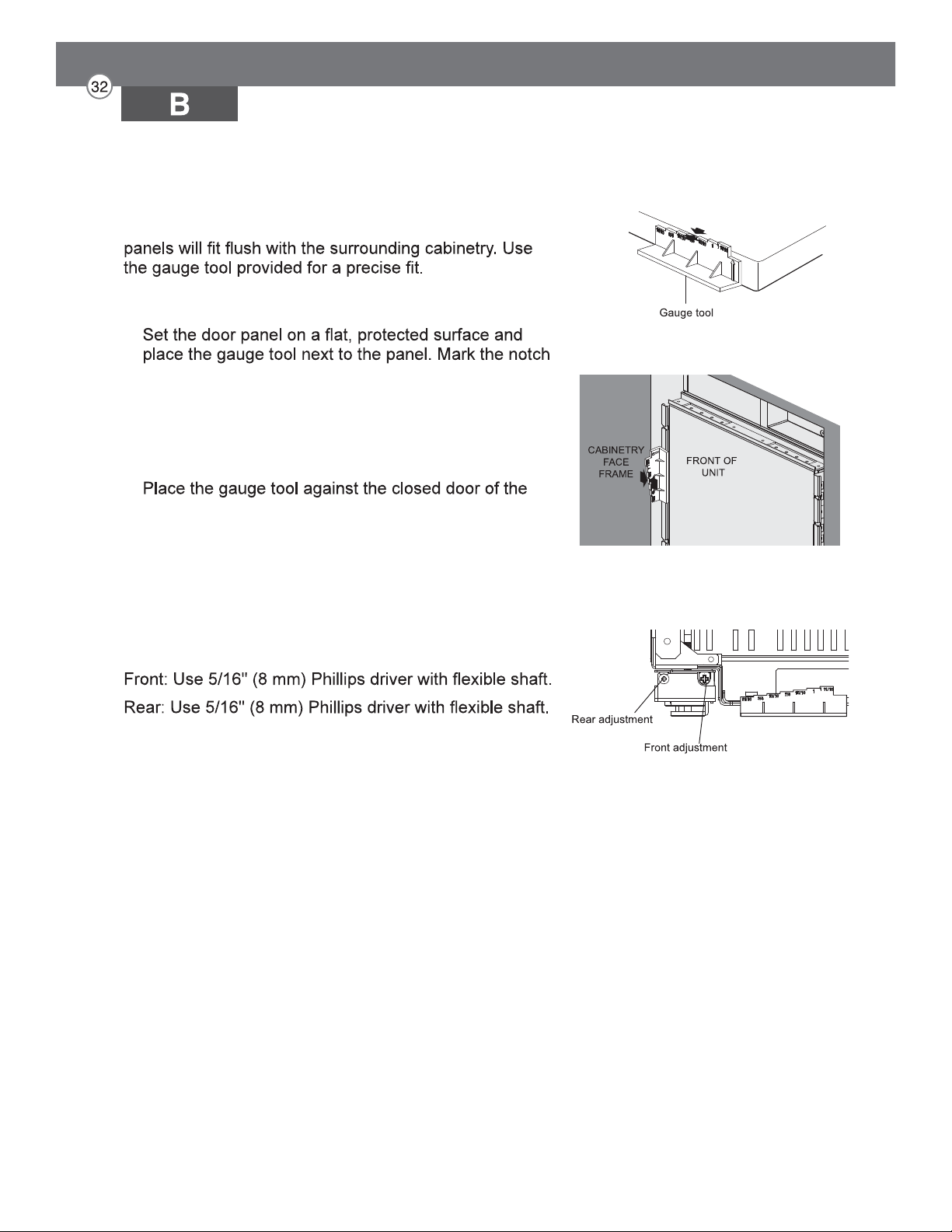
Adjust the depth of the unit in the enclosure so the door
1. Measure the thickness of your decorative door
panels using the gauge tool.
on the gauge tool that matches the thickness of the
door panel.
2. Use the mark on the gauge tool to adjust the depth
of the appliance in the enclosure.
appliance at the side of the enclosure. The marked
notch on the gauge tool should align with the front
edge of the enclosure.
HEIGHT ADJUSTMENT
The front and rear leveling legs can both be adjusted
from the front.
Measure panel thickness
Align depth of unit
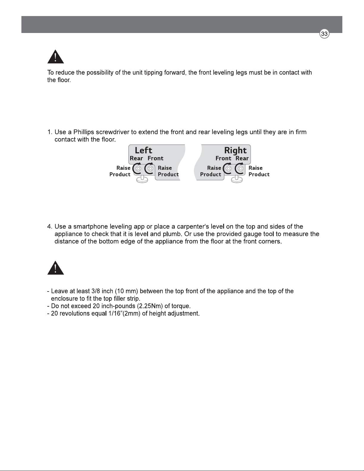
LEVELING
Once the appliance is aligned properly in the enclosure, level it using the front and rear leveling
legs.
2. Turn the screws as shown above to raise the appliance. Turn the screws in the opposite
direction to lower the appliance.
3. Make sure the weight of the refrigerator is carried on the legs, not the wheels.
WARNING
CAUTION
- If using a power drill, use the lowest torque setting.
Leveling
Attaching Appliance to Enclosure
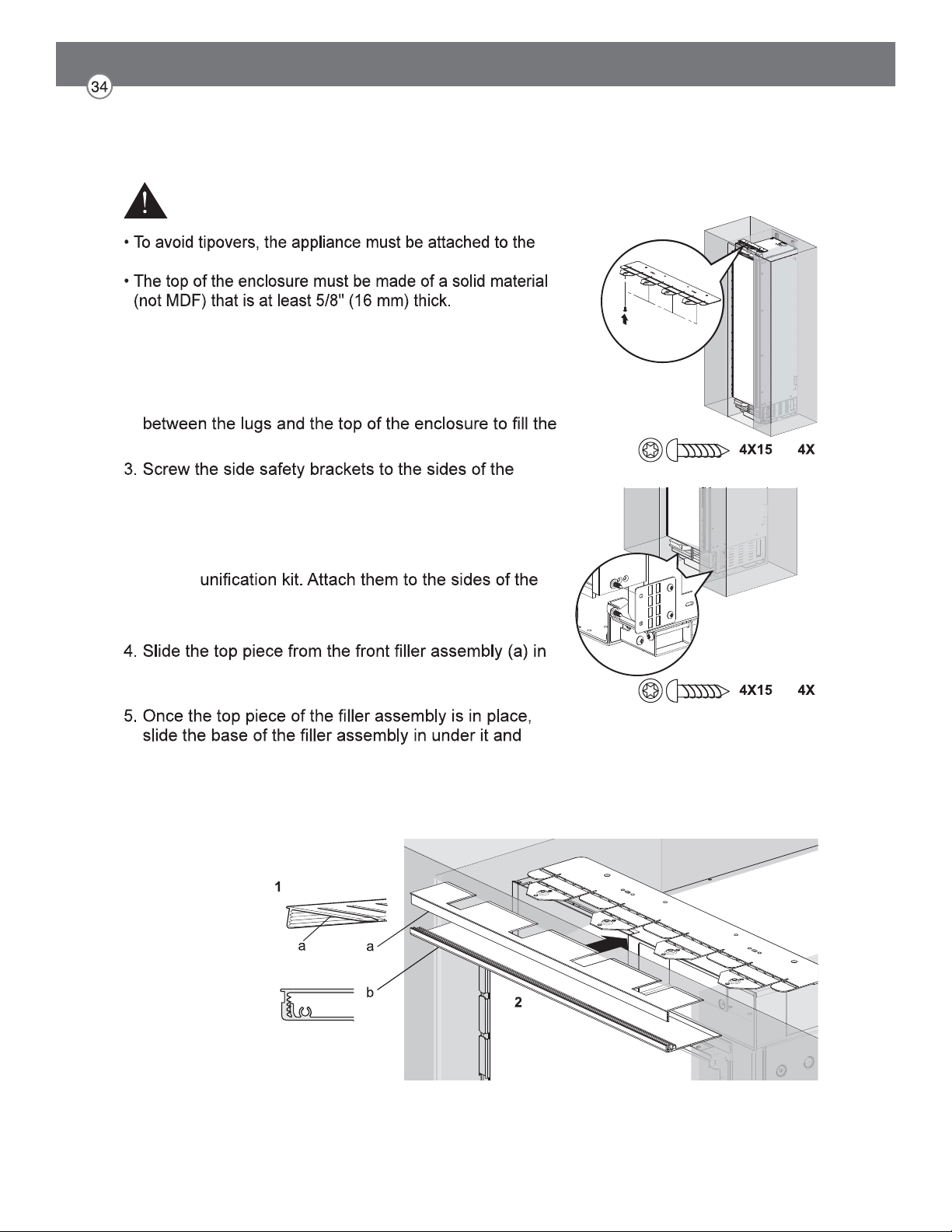
1. Screw the lugs on the safety bracket at the top of the
appliance to the top of the enclosure.
2. If there is a large gap between the top of the appliance
and the top of the enclosure, insert a piece of wood
gap.
enclosure.
NOTE: If installing two appliances side-by-side, attach
the appliances to each other using the
enclosure as if they were one unit.
at the top of the appliance until it engages with the top
safety bracket.
snap the top into the base (b).
NOTE: If installing two appliances side-by-side, attach
both top covers using the bolt found in the
accessories package.
WARNING
top of the enclosure.
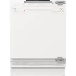
Attaching the Toe Kick Panel
Stainless Toe Kick Panel (Optional Accessory)
1. Screw the base panel to the appliance.
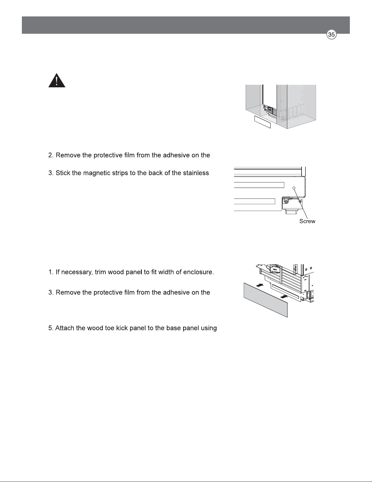
provided magnetic strips.
toe kick panel.
4. Attach the stainless toe kick panel to the base panel
using the magnetic strips.
Wood Toe Kick Panel
2. Screw the base panel to the appliance.
provided magnetic strips.
4. Stick the magnetic strips to the back of the wood toe
kick panel.
the magnetic strips.
CAUTION
To avoid damage to the appliance, do not block the
ventilation slots in the base panel.
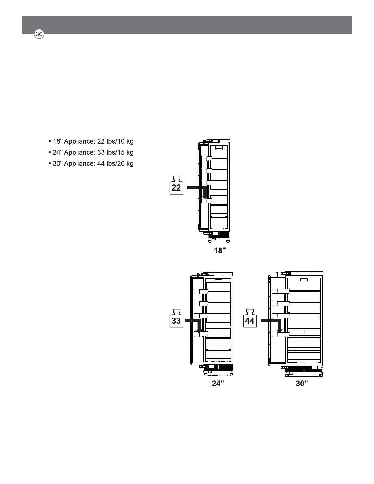
Loading the Appliance Door
For precise results, before attaching the door panels,
load the door bins with weights to ensure the gap width
remains correct after food is stored in the door.
Recommendations:
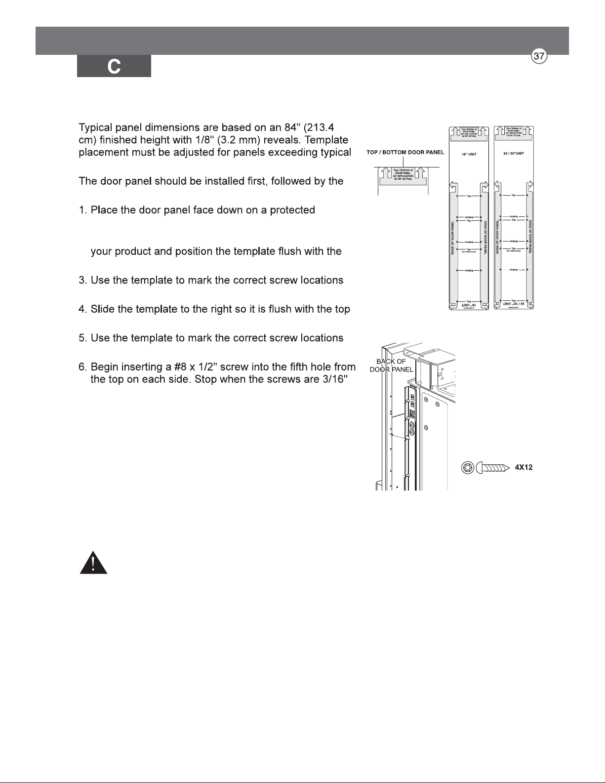
Installing Door Panels
dimensions.
upper then lower drawer panel, if needed.
surface.
2. Locate the correct side of the door panel template for
top and left sides of the panel.
on the back of the panel.
and right sides of the panel.
on the back of the panel.
(4 mm) proud of the panel. These will be the
support screws during the panel installation.
7. Insert the support screws in the slotted holes on the
appliance door mounting brackets so that the panel is
hanging on the door.
CAUTION
Beware of pinch points when installing door panels or opening
and closing doors.
Mounting door panel
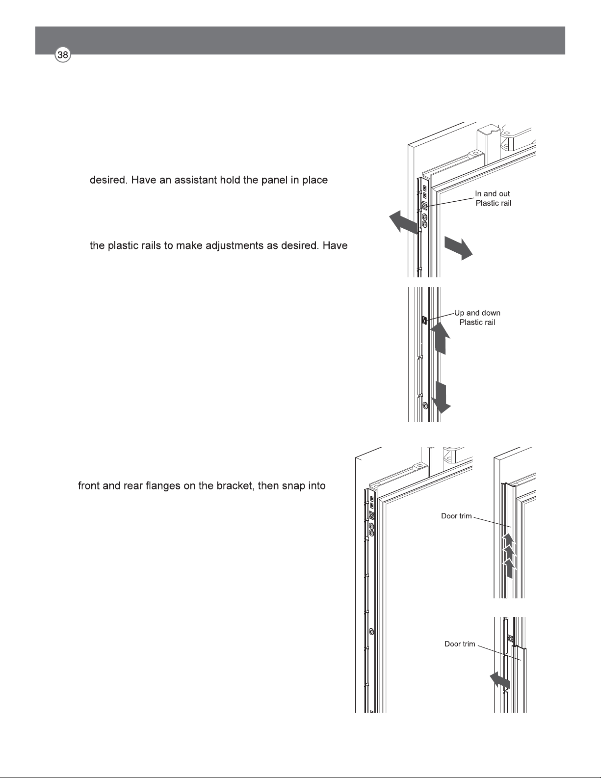
Adjusting Door Panels
Fine adjustments can now be made to align the door
panels.
1. To adjust the door panel horizontally, slide the panel
support screws left or right in the slotted holes as
while you tighten the support screws and insert and
tighten all remaining mounting screws.
2. To adjust the door panel vertically or back and forward,
loosen the screws in the appliance door bracket. Move
an assistant hold the bracket in place while you tighten
all the bracket screws.
Installing Door Trim
After panels have been adjusted, install the decorative
side trim on the doors.
To install, start at the middle and align the trim with the
place by pushing the trim toward the back of the panel.
Once the middle is secure, continue the installation
upward until the remaining trim is completely secure.
Attaching Air Separator
Special Installations
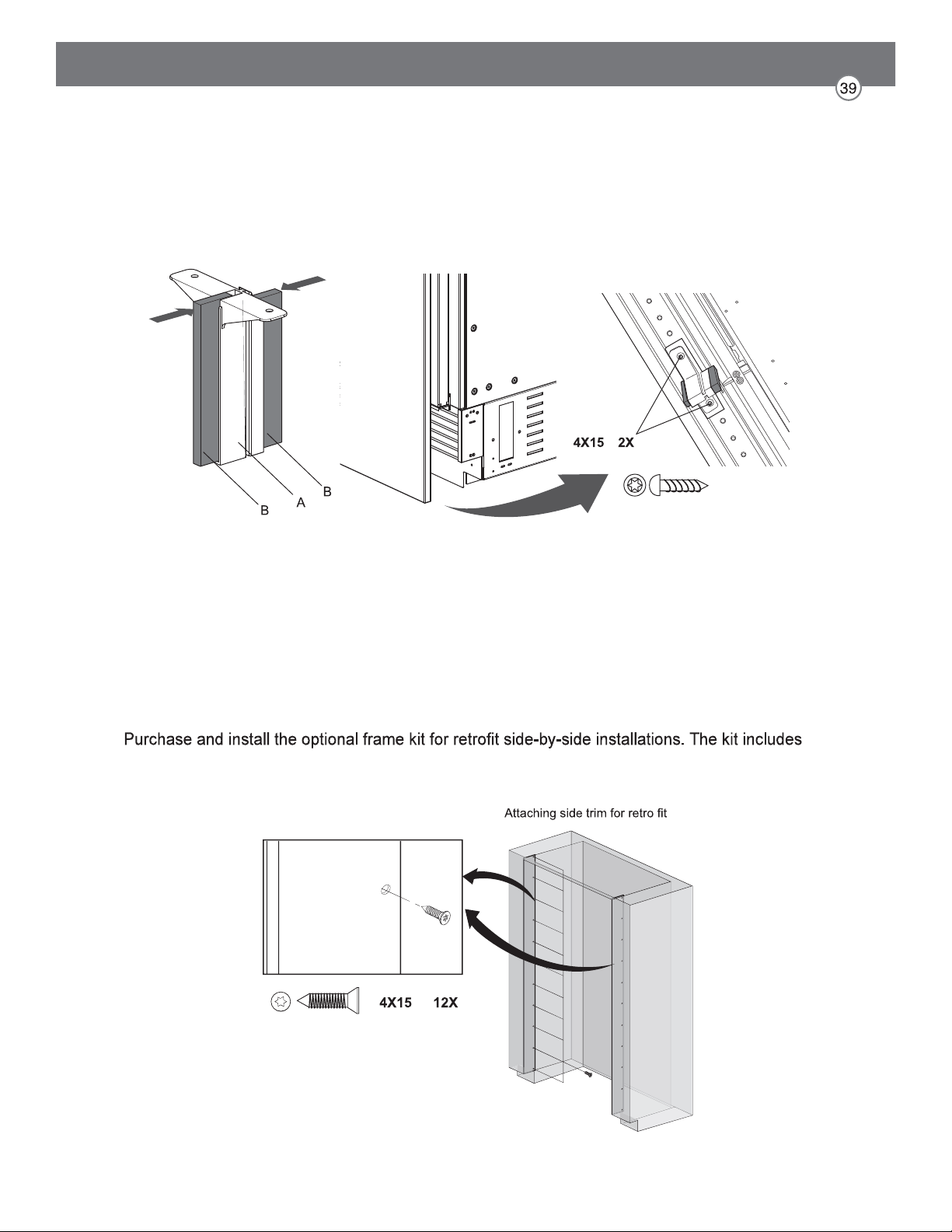
Optional Frame Kit Accessory
stainless trim pieces to cover the front edges inside the enclosure. See detailed installation
instructions with the kit.
Assemble A with B and attach on bottom front center of door.
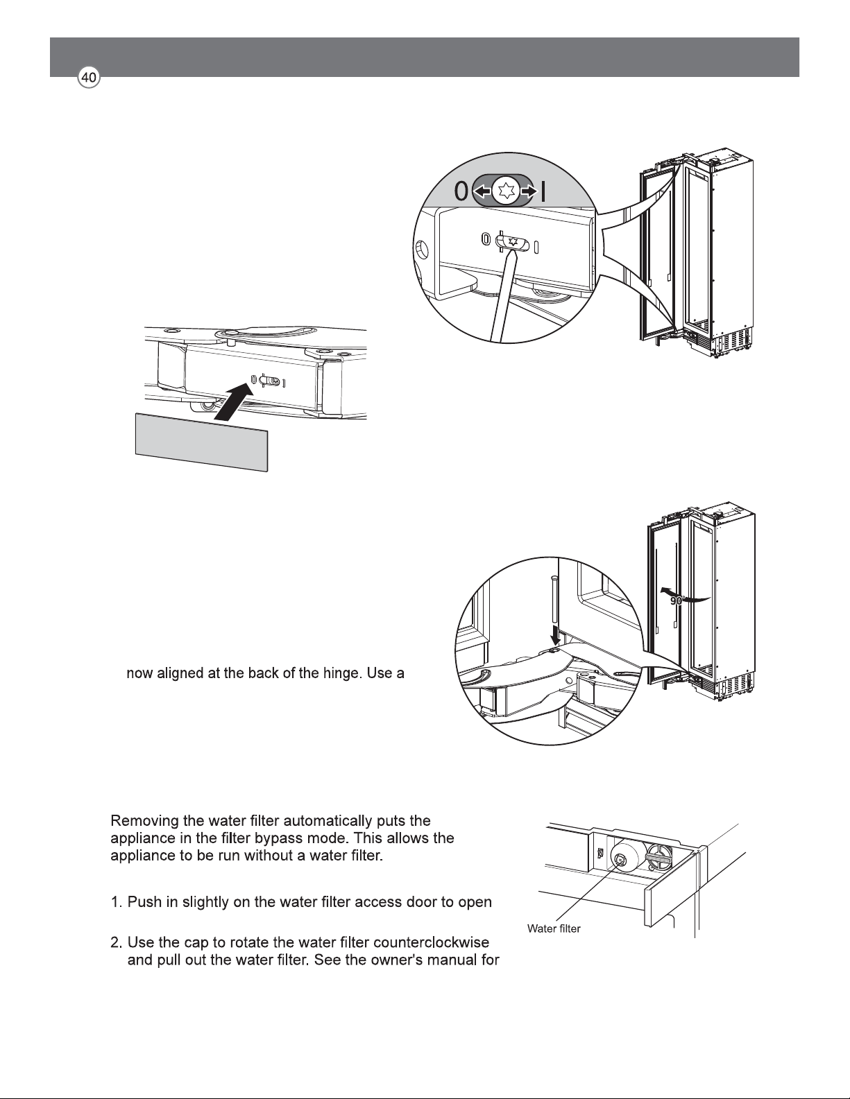
Adjusting the Door Spring
Adjusting the Door Stop
Rotate the adjusting screw with the T20 bit
provided.
I = maximum spring tension
0 = no spring tension
(Optional) After adjusting the door spring,
attach the gray plastic sheets to hide the
adjusting screws.
Water Filter Bypass
Removing the Water Filter
it.
detailed instructions.
The default door stop position is 115°. Follow
these instructions to change the door stop
position to 90°.
1. Open the door to 90°.
2. Insert the door stop pin in the holes which are
rubber mallet to fully insert the pin.
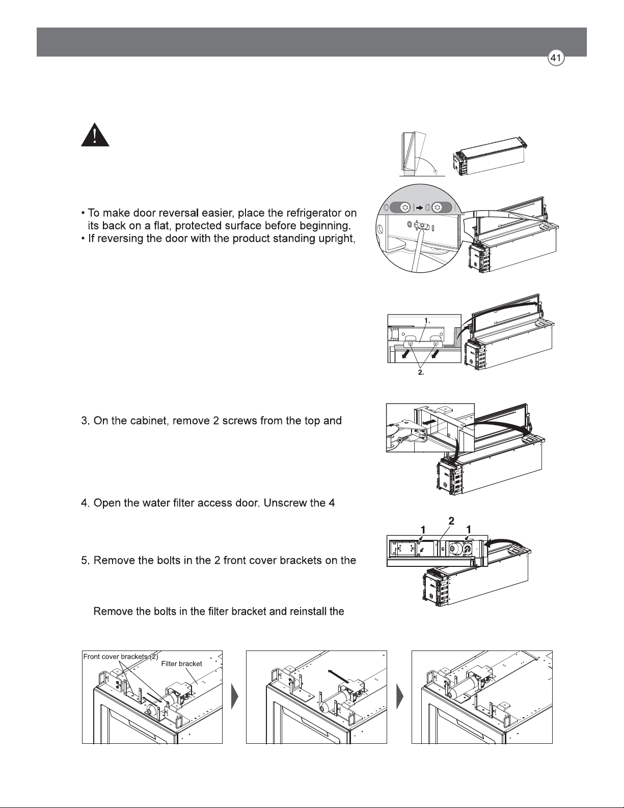
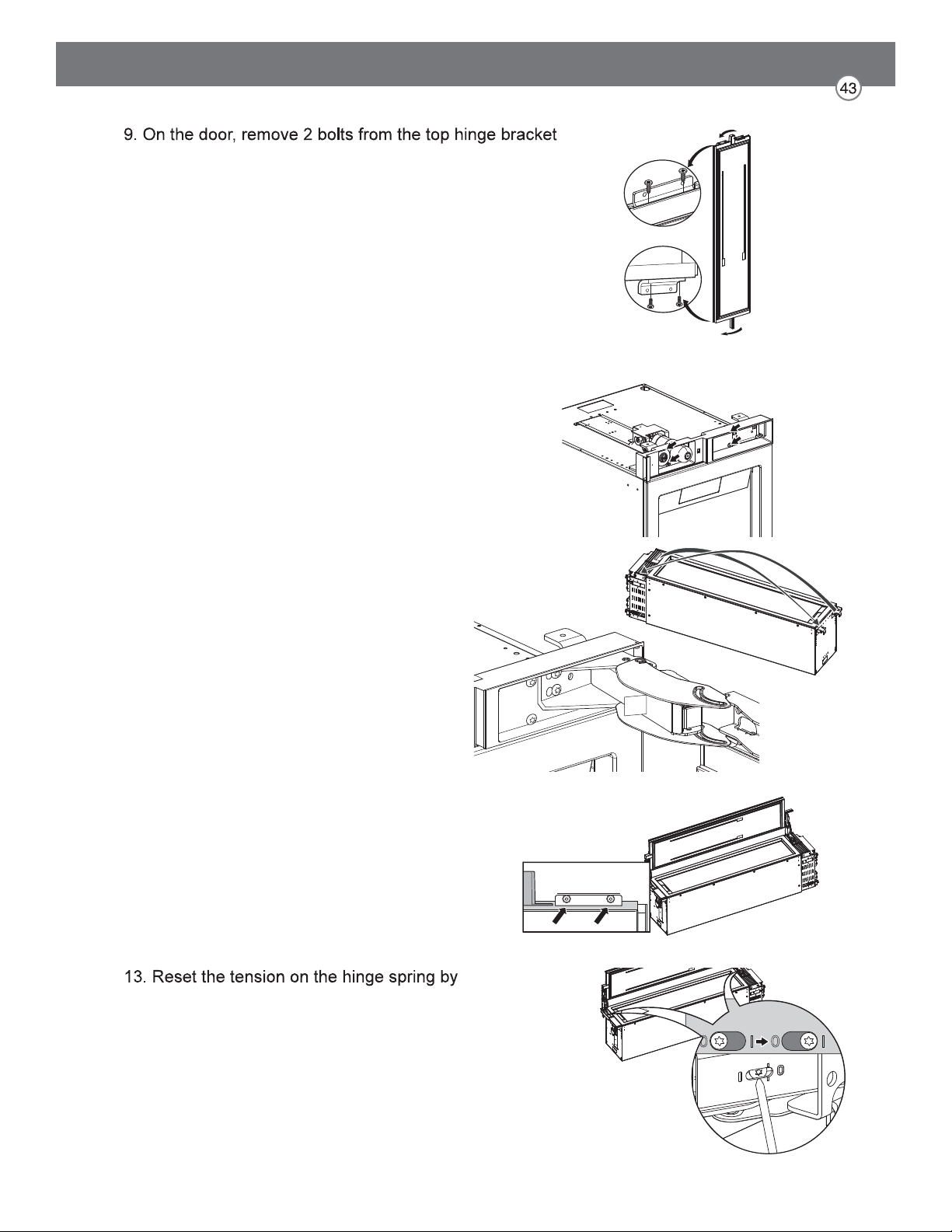
Reversing the Door
1. Open the door and release the tension on the hinge
spring by using the T20 bit provided to turn the screw
from | to O.
2. If the air separator is attached, remove it. Remove the
2 mounting bolts at the top and bottom of the door (1).
Remove the door (2) and lay it aside on a protected
surface.
bottom hinges, remove the hinges, and lay the parts
aside.
screws (1) and remove the front cover assembly (2).
top of the appliance. Swap the positions of the 2
brackets, rotating one 180 degrees, and reinstall the
bolts.
bracket assembly on the opposite side.
WARNING
Risk of Injury
Before working on the hinge, release the tension on the
hinge spring.
NOTE:
the door MUST be supported while removing or
installing mounting bolts.
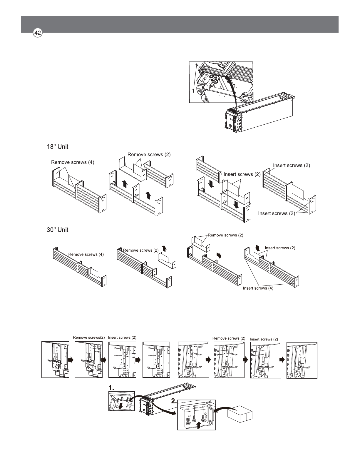
6. Unscrew and remove the vent cover assembly at the bottom of the appliance.
7. Follow the diagrams below to disassemble and
reassemble the vent grille. Screw the vent cover assembly back onto the appliance.
8. Remove the lower hinge socket. Install the hinge socket provided in the installation
accessories on the opposite side. Keep all parts in case door is reversed in future.
and install the bracket on the opposite side of the door.
Repeat with the bottom hinge bracket.
10. Rotate the front cover 180 degrees and reinstall it at
the top of the cabinet.
11. Install the hinge removed from the top of the cabinet
on the opposite side at the bottom of the
cabinet.
Install the hinge removed from the bottom
of the cabinet on the opposite side at the
top of the cabinet.
12. Insert 2 bolts at the top and bottom of the door
to reattach the door.
using the T20 bit provided to turn the tension
screw from O to |.
14. Stand the product upright. The power cord can
be connected, but wait 24 hours before turning
on the power.
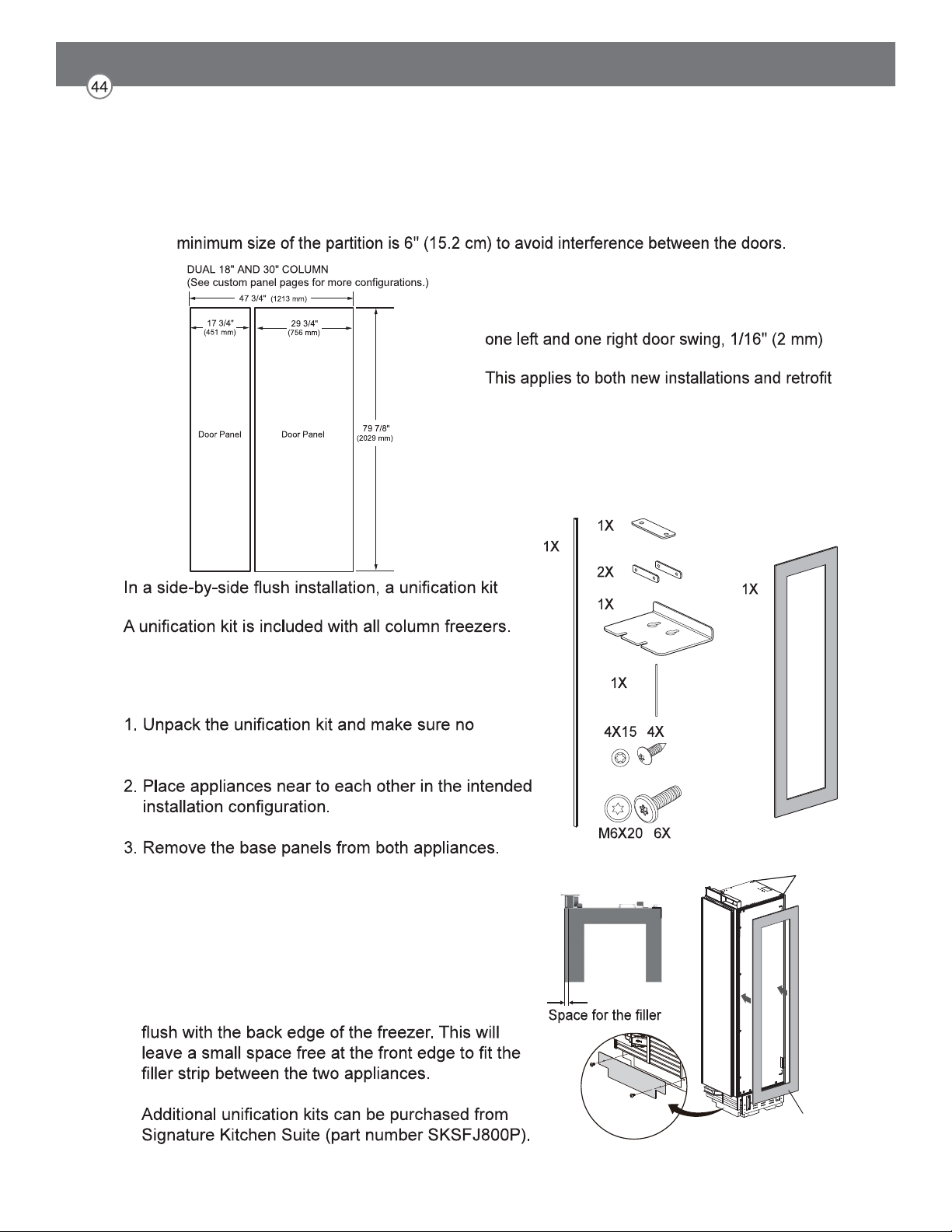
Side-by-Side Flush Installation
FLUSH INSTALLATION CLEARANCES
must be used to seal the appliances together.
The kit contains a sealing mat which helps prevent
condensation from forming between the two
appliances.
accessories are missing.
4. Attach the included sealing mat on the side of the
freezer that faces the refrigerator. (The sealing mat
should be between the two appliances after they
are connected.)
Install the gray sealing mat over the preinstalled
black sealing strips so that the edge of the mat is
sealing mat
strip
sealing strip
(both sides)
NOTE: When installing products with a partition between them, follow the standard installation. The
NOTE:
When installing 2 side-by-side products with
clearance is required between the products.
installations.
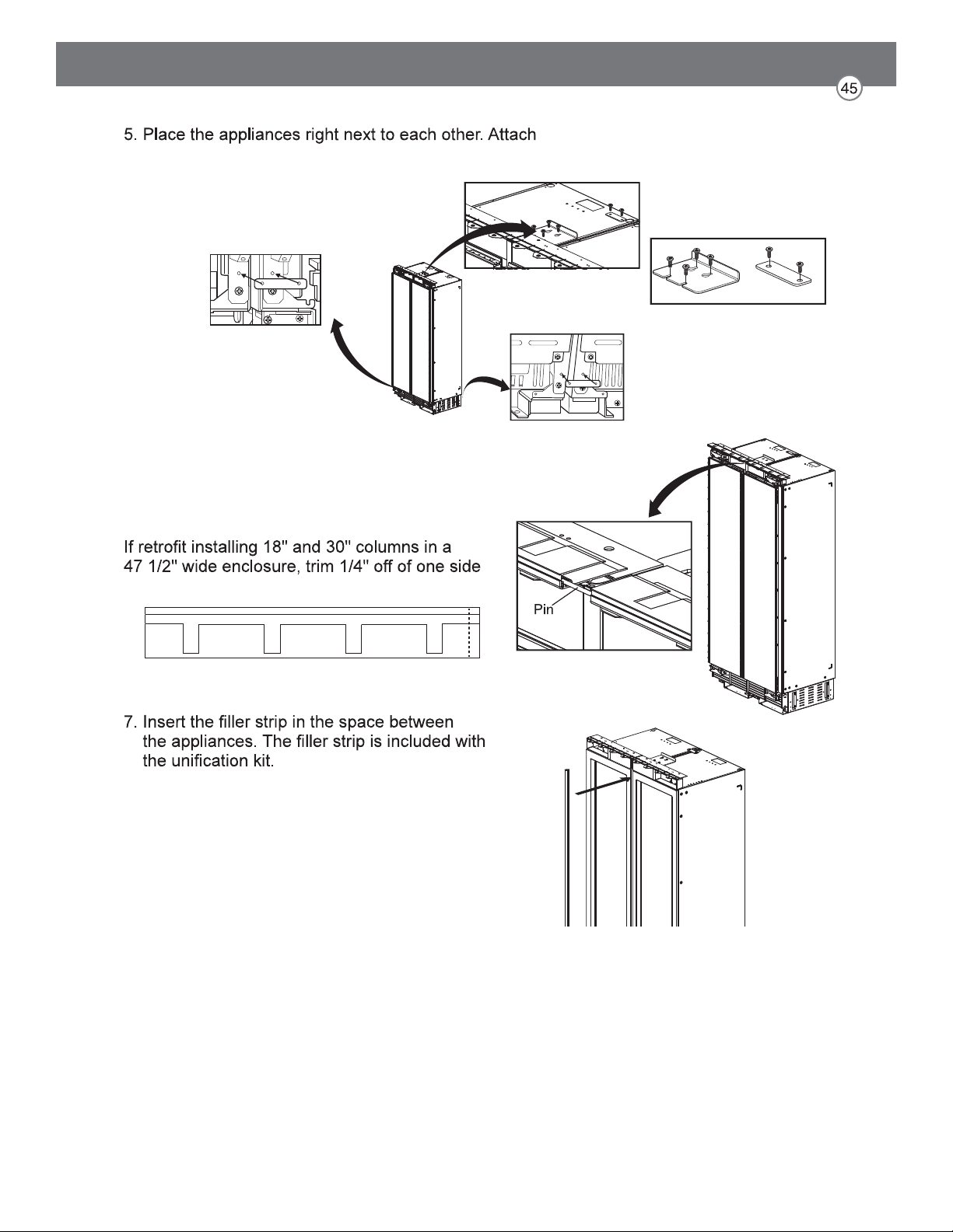
the two appliances together by installing connection
brackets between the two appliances at
top and bottom.
6. Insert the provided pin into both cover rails at the
top of the combined units.
NOTE:
of both cover rails.
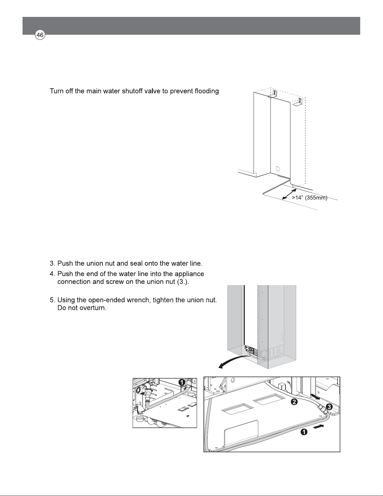
Preparing to Connect the Water Line
NOTE:
and property damage.
Install the water line.
Always observe the indicated dimensions to prevent
damage to the water line when pushing in the appliance
Connecting Water Line
NOTE:
When bending the water line, do not kink it, otherwise
there is a risk of leaks and water damage.
1. Remove the cap from the appliance connection (1.).
2. Bend the water line according to the location of the
connection on the appliance (2.).
Tighten hand-tight.
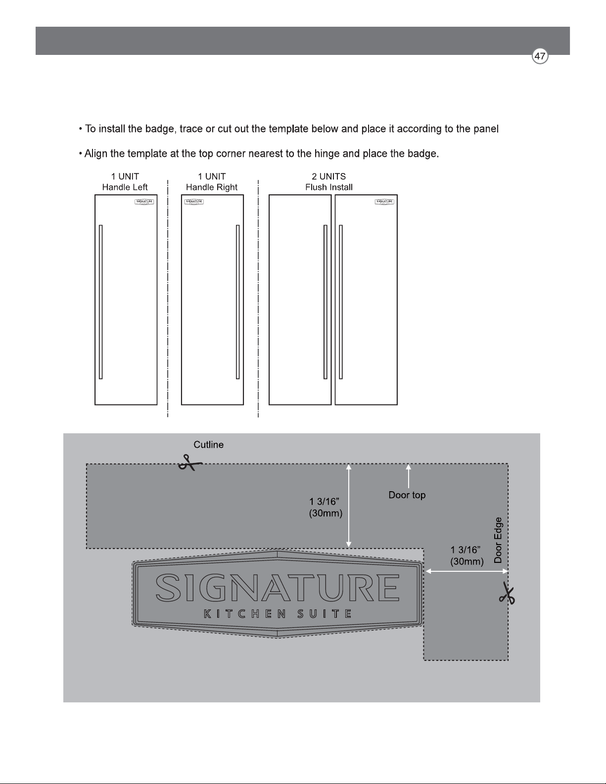
Attaching the Badge
layouts below.