Loading ...
Loading ...
Loading ...
Application Guide - 7
EdgeMax Design Considerations
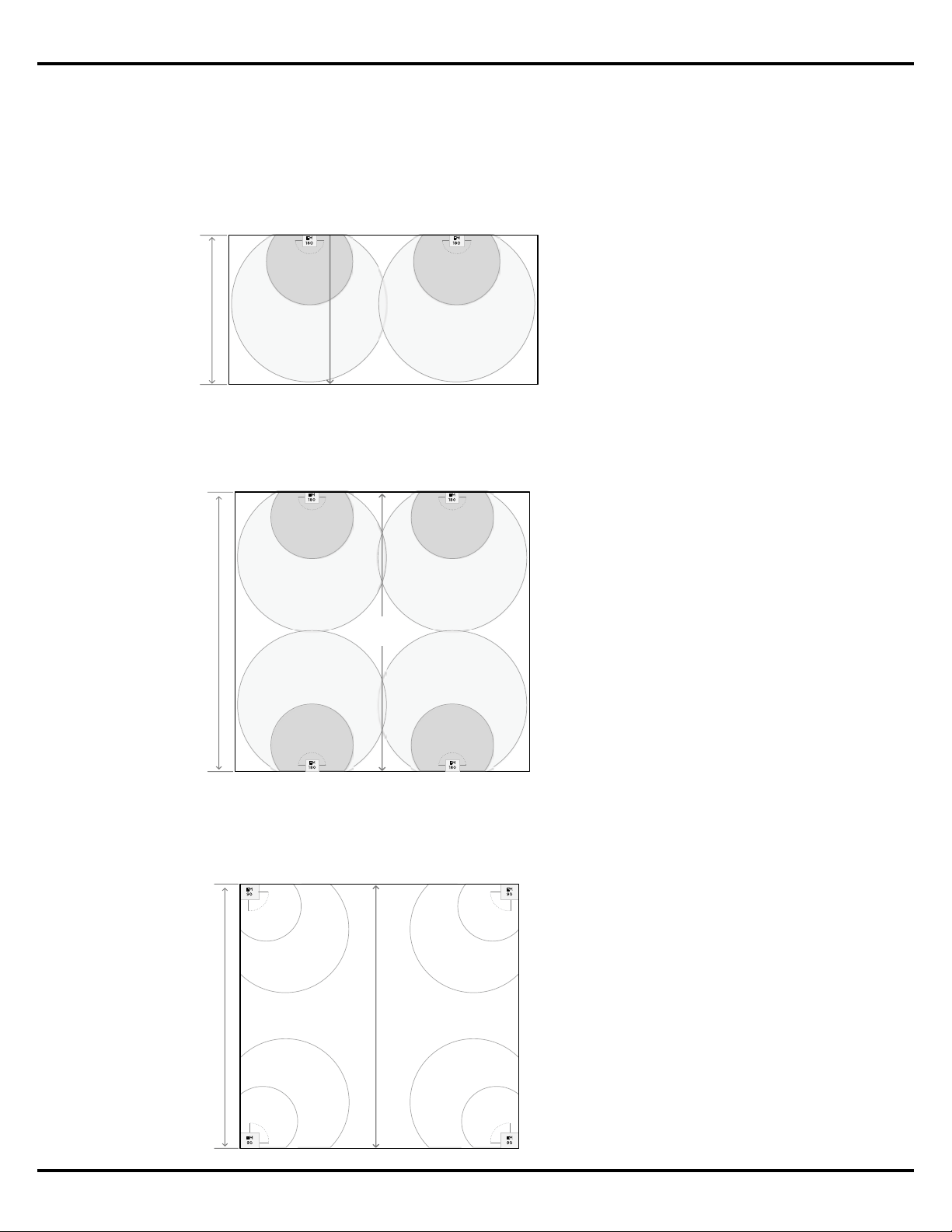
The following are two examples of how the Maximum Room Dimension is applied in an
EdgeMax design. The first is when EdgeMax loudspeakers are used along one side of the
coverage area. The second is when they are installed along both sides of the coverage area.
When placing EdgeMax loudspeakers along one side of the coverage area, the Maximum
Room Dimension should be less than or equal to the Usable Throw Distance.
In applications where EdgeMax loudspeakers will be mounted on two opposing sides of the
room, the Maximum Room Dimension is twice the Usable Throw Distance for the planned
ceiling height.
4.2 m | 14 ft ceiling
EM180 Single Wall Mounting
E
M
1
80
Maximum Room Dimension
(8 m | 25 ft)
E
M
1
8
0
Usable
Throw
Distance
Figure 8. The Maximum Room
Dimension is less than or equal
to the Usable Throw Distance
when EdgeMax loudspeakers
are placed along one edge of
the area to be covered.
Figure 9. The Maximum Room
Dimension is equal to twice
the Usable Throw Distance
when EdgeMax loudspeakers
are mounted on two opposing
sides of the area to be covered.
4.2 m | 14 ft ceiling
EM180 Perimeter Mounting
E
M
18
0
Maximum Room Dimension
(16 m | 50 ft)
E
M
1
80
EM
180
EM
180
2x Usable
Throw
Distance
The Maximum Room Dimension is applied to EdgeMax designs to prevent the creation of a
design which lacks sucient coverage in the center of the room – particularly in the case of a
square room where EM90 loudspeakers are used in the corners.
Figure 10. In this example the
Maximum Room Dimension has
been exceeded, resulting in a
coverage gap in the center of
the room.
E
M
9
0
4.2 m | 14 ft ceiling
EM90 Corner Mounting
Exceeds Maximum Room Dimension
> 2 x Usable Throw Distance
E
M
9
0
E
M
9
0
E
M
9
0
Loading ...
Loading ...
Loading ...