Loading ...
Loading ...
Loading ...
28 - Installation Guide
Installation
pro.Bose.com
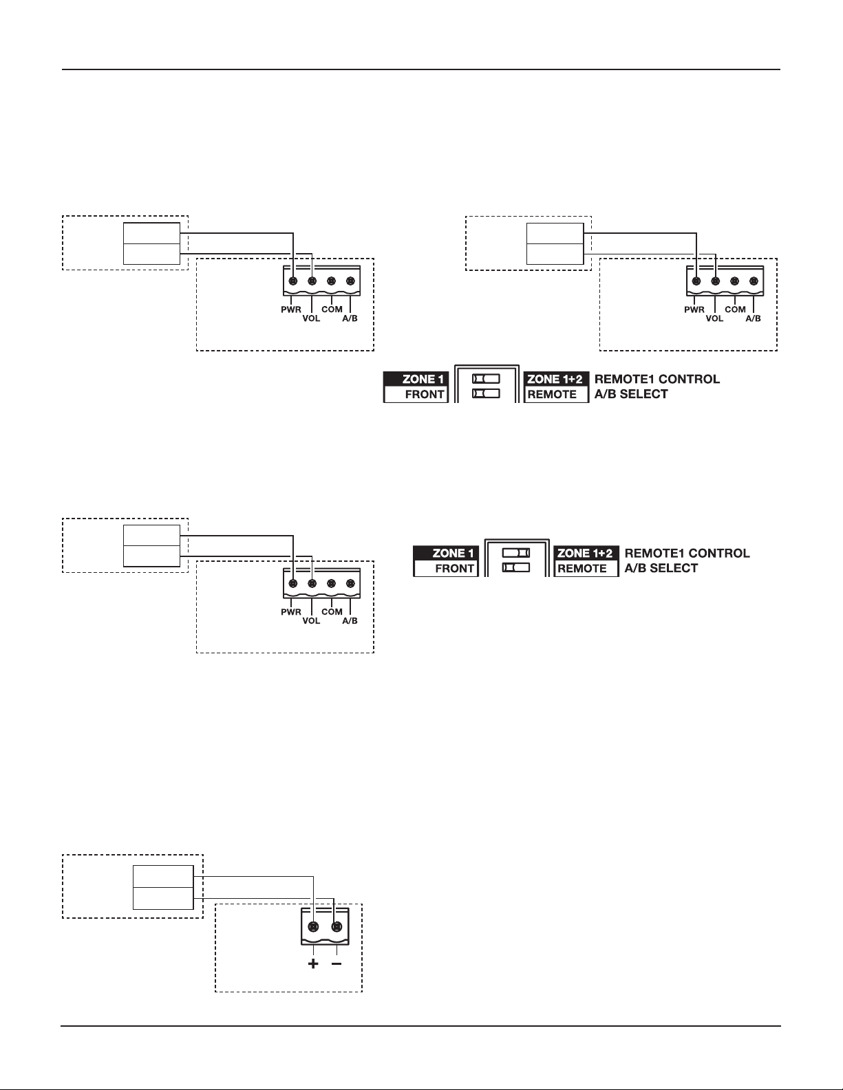
Configuration example #4:
REMOTE 1 and REMOTE 2 can be a volume control user interface accessory (PC 041966). In this
configuration, REMOTE 1 controls the level of output one and REMOTE 2 controls the level for output
two. A/B source selection for both outputs is simultaneously controlled by the front panel switch. This
configuration requires setting the REMOTE 1 CONTROL DIP switch to ZONE 1 and the A/B SELECT DIP
switch to FRONT.
Configuration example #5:
REMOTE 1 can be a volume control user interface accessory (PC 041966). In this configuration, REMOTE 1
controls the level of both outputs simultaneously. A/B source selection for both outputs is simultaneously
controlled by the front panel switch. This configuration requires setting the REMOTE 1 CONTROL DIP
switch to ZONE 1+2 and the A/B SELECT DIP switch to FRONT.
Bose
volume
control
1 PW
R
2 VOL
IZA 2120-HZ
REMOTE 1
Bose
volume
control
1 PW
R
2 VOL
IZA 2120-HZ
REMOTE 2
DIP switch settings
Bose
volume
control
1 PW
R
2 VOL
IZA 2120-HZ
REMOTE 1
DIP switch settings
Remote Connections to Zone Amplifiers
Remote volume control
The zone amplifiers are designed to work with the Bose
®
volume control user interface accessory
(PC041966). The REMOTE connector on the rear panel of the amplifier is labeled to match the connector
on the user interface. Use the included 2-pin Euroblock. See the Bose volume control user interface
accessory install guide for more details.
1 PW
R
2 VOL
REMOTE 1
ZA 2120-LZ/HZ
Bose
volume
control
Loading ...
Loading ...
Loading ...