Loading ...
Loading ...
Loading ...
Page 12
POOL PATROL PA-25 & PA-30
approximately 2' of slack in the string for the alarm to function and be
removed easily. Tie down locations should be as close to the water level
as possible for the best results. You can tie down to your ladder, diving
board, or the plastic hooks that are supplied.
Do not place your alarm next to the filter return. The filter inlet of your
pool should be pointed downward (Figure 8) at an angle toward the
bottom of the pool and away from the water surface. This will reduce any
surface waves and will help to avoid any false alarms when the pump
turns on.
Soft Sided Pools
Tie one end of the string to the tab on the float (Figure 7), leave about 2-
3 foot of slack, tie the other end of the sting to either a adder or another
fixed area.
IMPORTANT
Do not apply adhesive-backed hooks to your pool as removal of
the hooks may tear your pool.
Figure 8 Filter Inlet Position
Correct Incorrect
Page 13
POOL PATROL PA-25 & PA-30
RECEIVER
Your receiver works with the pool alarm allowing you to monitor your pool
from within your house. When the floating alarm is activated it sends a
signal to activate the receiver.
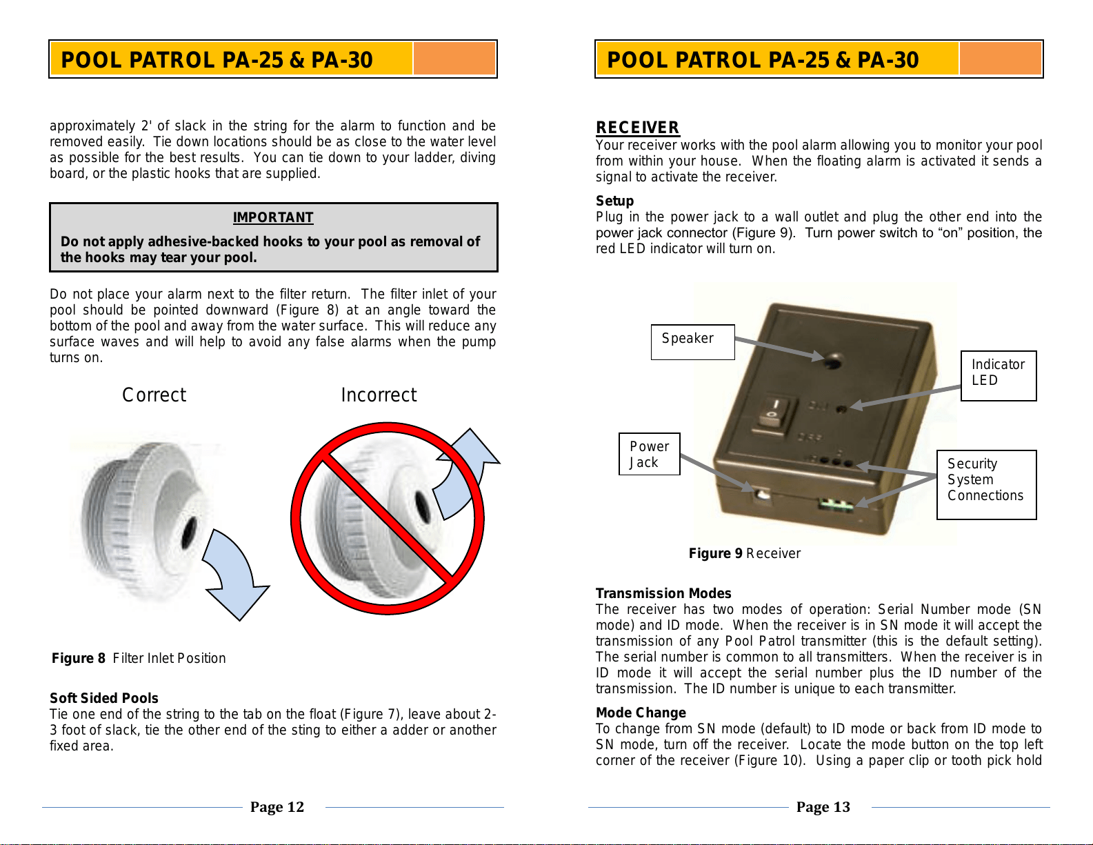
Setup
Plug in the power jack to a wall outlet and plug the other end into the
power jack connector (Figure 9). Turn power switch to “on” position, the
red LED indicator will turn on.
Transmission Modes
The receiver has two modes of operation: Serial Number mode (SN
mode) and ID mode. When the receiver is in SN mode it will accept the
transmission of any Pool Patrol transmitter (this is the default setting).
The serial number is common to all transmitters. When the receiver is in
ID mode it will accept the serial number plus the ID number of the
transmission. The ID number is unique to each transmitter.
Mode Change
To change from SN mode (default) to ID mode or back from ID mode to
SN mode, turn off the receiver. Locate the mode button on the top left
corner of the receiver (Figure 10). Using a paper clip or tooth pick hold
Power
Jack
Speaker
Indicator
LED
Security
System
Connections
Figure 9 Receiver