Loading ...
Loading ...
Loading ...
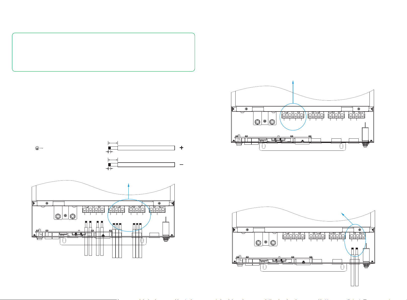
2.5 PV Connection
Please follow below steps to implement PV module connection:
1. Remove insulation sleeve 10 mm for positive and negative conductors.
2. Check correct polarity of connection cable from PV modules and PV input connectors.
3. Connect positive pole (+) of connection cable to positive pole (+) of PV input connector. Connect negative
pole (-) of connection cable to negative pole (-) of PV input connector.
4. Make sure the wires are securely connected.
5. Finally, after connecting all wiring, please put bottom cover back by screwing two screws as shown below.
2.6 Generator Connection
N→Neutral (blue)L→LINE (brown or black)
1. Before making Generator connection, be sure to open DC protector or disconnected first.
2. Remove insulation sleeve 10mm for 2 conductors.
3. Insert L and N wires according to polarities indicated on terminal block and tighten the terminal screws
PVA+ PVA- PVB+ PVB- L N PE
AC INPUT
L N PE
AC OUTPUT
L N
GEN
BAT+ BAT-
2.4 AC Input/Output Connection
CAUTION!!
- There are two terminal blocks with “IN” and “OUT” markings. Please do NOT mis-connect input and
output connectors.
Please follow below steps to implement AC input/output connection:
1. Before making AC input/output connection, be sure to open DC protector or disconnected first.
2. Remove insulation sleeve 10mm for six conductors. And shorten phase L and neutral conductor N 3 mm.
3. Insert AC input wires according to polarities indicated on terminal block and tighten the terminal screws.
Be sure to connect PE protective conductor first.
Ground
(yellow-green)
N→Neutral (blue)
4. Insert AC output wires according to polarities indicated on terminal block and tighten terminal screws.
Be sure to connect PE protective conductor first.
5. Make sure the wires are securely connected.
- Be sure to connect AC wires with correct polarity. If L and N wires are connected reversely, it may
cause utility short-circuited when these inverters are worked in parallel operation.
L→LINE (brown or black)
10
3
10
3
PVA+ PVA- PVB+ PVB- L N PE
AC INPUT
L N PE
AC OUTPUT
L N
GEN
BAT+ BAT-
PVA+ PVA- PVB+ PVB- L N PE
AC INPUT
L N PE
AC OUTPUT
L N
GEN
BAT+ BAT-
09
10
Loading ...
Loading ...
Loading ...