Loading ...
Loading ...
Loading ...
12 PD3000 Quick Start Guide 13
1. Introduction
1.1 Welcome
Thank you for choosing a Lab.gruppen PD3000. This manual provides a comprehensive guide to the features and functionality of the PD3000 amplier. We highly
recommend you read through this manual in its entirety to become fully acquainted with conguration options and protection circuitry. As you become thoroughly
familiar with all aspects of operation, you may learn of features or options that will aect your choices on amplier modes or loudspeaker system conguration.
Lab.gruppen PD3000 power ampliers are designed and built with competitive price and good performance and protection features in mind. Although the PD3000
amplier features a competitive price, each amplier draws on the engineering that has made Lab.gruppen the benchmark of quality for touring concert systems:
exceptional sonic performance, rugged construction, proven reliability, and protection features that anticipate every unwelcome possibility – that is the core of
the “Show must go on” design philosophy that every Lab.gruppen product is created with, with a well matched feature set per product range depending on the
expected application.
1.2 Features
Your new PD3000 amplier incorporates a number of sophisticated technologies – many of them proprietary to Lab.gruppen – that ensure the best
possible performance and years of reliable operation. Familiarizing yourself with these technologies will prove invaluable in setting up and optimizing your
loudspeaker system.
1.3 Class D output stage
PD3000 ampliers employ our unique IDEEA Class D output stage that is ideally matched to the rated power output. To provide exibility, each channel oers sucient
voltage swing and current capacity to drive loads in any impedance without any additional conguration. In order to have low thermal losses as well as a high voltage
swing, the design is based on a permanently bridged output.
1.4 Protection and performance optimization
Appropriate and reliable power amplication is vital to any audio system. Inadequate or faulty power ampliers could cause damage to loudspeakers, or in some
cases to the power ampliers themselves. To prevent damage or service interruptions, PD3000 ampliers oer advanced features to protect both internal circuits and
connected loads. These features are part of the Lab.gruppen “Show must go on” philosophy.
PD3000 protection features include:
• CPL (Current Peak Limiter) ensures that the amplier’s output does not exceed the safe current handling parameters of the amplier components.
• Temperature protection ensures that the amplier will not be damaged by exceeding thermal limits. The RDY LED ashes orange when the amplier approaches
thermal limits to allow user action before protective muting engages.
• DC protection ensures destructive DC signals will not appear at the amplier outputs. If such conditions occur an internal fuse opens.
• RSL (Rail Sensing Limiter) is applied to avoid distortion at the selected voltage limit threshold and to avoid hitting the rail if it has sagged below the congured
threshold. Limiting also may be applied when maximum output current has been reached or when the mains voltage is too low to maintain required rail voltage.
Limiting activity is shown by the front panel Limiter LED
1.5 Unpacking and visual checks
Every Lab.gruppen amplier is carefully tested and inspected before leaving the factory and should arrive in perfect condition. If any damage is discovered, please
notify the shipping carrier immediately.
Save the packing materials for the carrier’s inspection and for any future shipping.
1.6 Cooling
PD3000 ampliers use a forced-air cooling system with front to rear airow, allowing high continuous power levels without thermal problems.
Please ensure that there is sucient space in the front and rear of each amplier to allow free ow of air, no doors or covers should be mounted either in the front or
rear of the ampliers.
Ampliers may be stacked directly on top of each other with no spacing, though some spacing may enable more convenient installation of rear cabling.
Fit solid blanks (not ventilation blanks) to unused rack spaces to ensure eective air circulation. Leaving gaps in between items of equipment degrades the
eectiveness of forced-air cooling.
1.7 Operating voltage
Always connect your PD amplier to the voltage specied on the rear of the device. Connecting the amp to an incorrect voltage can permanently damage your amp.
• USA / Canada / Japan = 100-120 V~, 50/60 Hz
• UK / Australia / Europe / Korea / China 220-240 V~, 50/60 Hz
The locking IEC receptacle on the rear panel accepts the supplied IEC cord which terminates in a connector appropriate for the country of sale.
2. Control
2.1 Front Panel
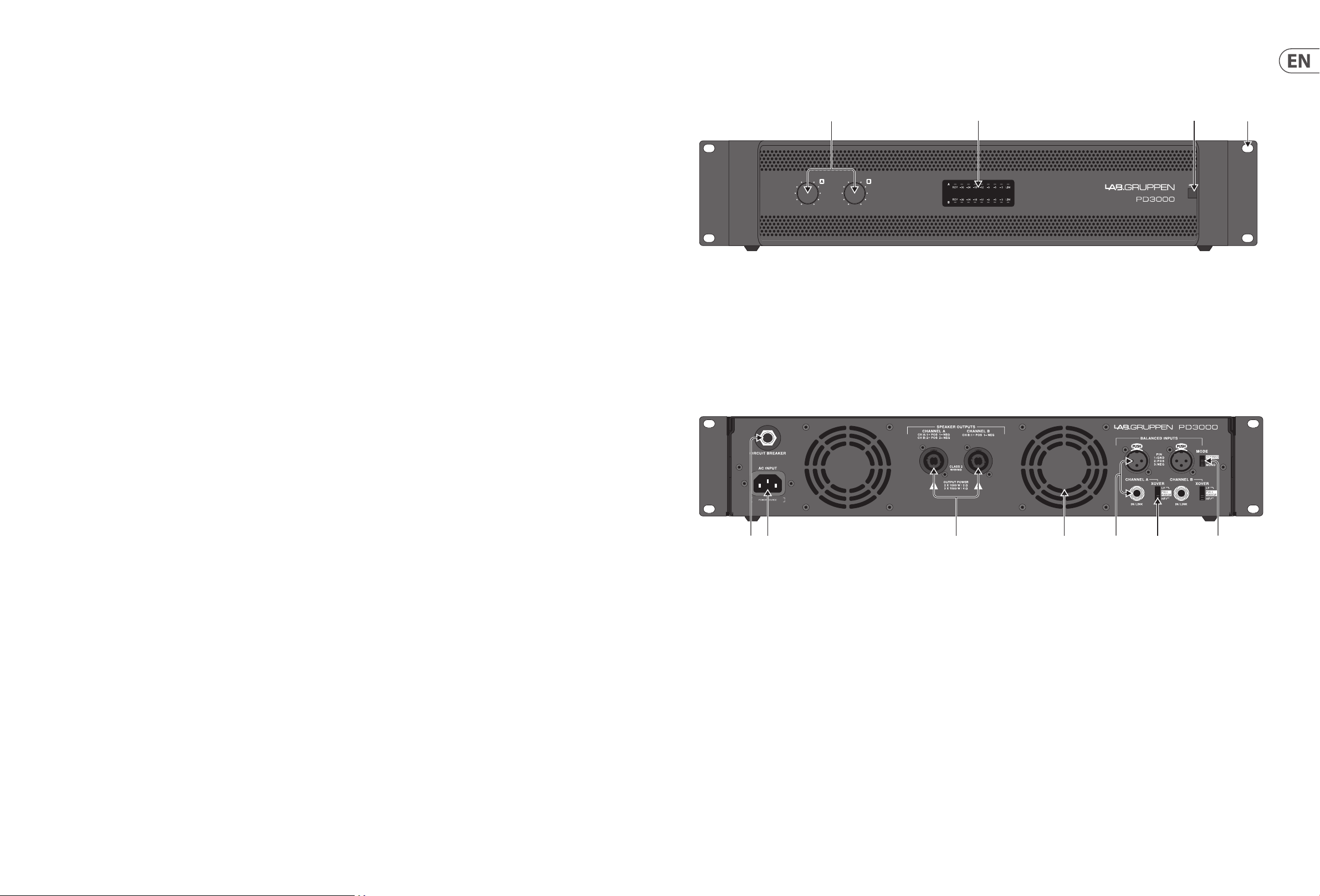
The following indicators and controls are available on the front panel (Fig. 1):
Fig. 1: PD3000 Front Panel
(1) CH A/CH B CONTROLS adjust the input level. To increase signal gain, rotate the knobs clockwise; to reduce the gain, rotate the knobs counter-clockwise.
(2) RDY, SIGNAL and LIM LEDs display the signal level and system status for each channel. RDY LED lights to indicate that the amplier is powered on. The SIGNAL
LEDs light to show the input signal level. The LIM LED lights when the input signal exceeds an optimum level and activates the internal limiter. Reduce the input
gain if the red LIM LED lights up continuously.
(3) POWER button turns the unit o and on.
(4) RACK EARS secure the unit into a rack using four attaching screws and washers (fasteners not included). Requires two rack units.
2.2 Rear Panel
The following connectors are available on the rear panel (Fig. 2):
Fig. 2: PD3000 Rear Panel
(5) BREAKER (automated fuse) acts in place of common discardable fuses. After eliminating the cause of faulty operation, simply depress the BREAKER and power
up the unit again. The BREAKER acts in place of common discardable fuses.
BREAKER WARNING: Take the following actions BEFORE resetting the breaker:
• Unplug the AC main cable
• Move the POWER switch to the “OFF” position
• Turn all input gain control elements down
• And then, reset the breaker, connect the unit to the mains, switch ON and slowly increase the gain to the target volume
(6) POWER SOURCE jack accepts the included IEC power cable.
(7) SPEAKER OUTPUTS connect the amplier to the speakers using professional speaker cables with twist-locking speakON plugs. Both output channels are
available by using a 4-pole connector and cable with the CHANNEL A output. CHANNEL B is available separately on the right-hand CHANNEL B output.
WARNING! Bridge Mode is not supported!
WARNING! Do not connect any output connector poles to ground!
(8) VENTILATION FAN speed adjusts automatically depending on temperature to ensure trouble-free operation.
(1) (3) (4)(2)
(7) (9) (10) (11)(5) (6) (8)
Loading ...
Loading ...
Loading ...