Loading ...
Loading ...
Loading ...
10
© 2021 United States Stove Company
INSTALLATION
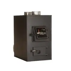
6” (152.4 mm) space. There should also be a support
sized to fit and hold the metal chimney connector. See
that the supports are fastened securely to wall surfaces
on all sides. Make sure fasteners used to secure the metal
chimney connector do not penetrate chimney flue liner.
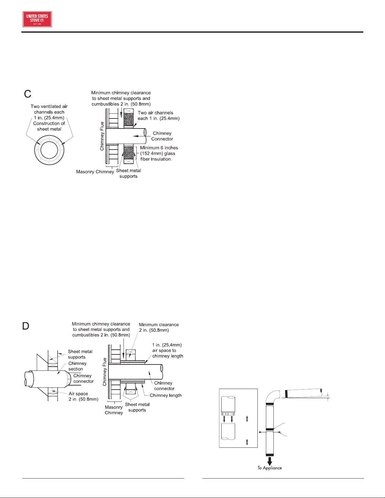
Method D - 2” (50.8 mm) Clearance to Combustible
Wall Member: Start with a solid-pak listed factory
built chimney section at least 12” (304 mm) long, with
insulation of 1” (25.4 mm) or more, and an inside diameter
of 8” (2 inches [51 mm] larger than the 6” [152.4 mm]
chimney connector). Use this as a pass-through for a
minimum 24-gauge single wall steel chimney connector.
Keep solid-pak section concentric with and spaced 1”
(25.4 mm) o the chimney connector by way of sheet
metal support plates at both ends of chimney section.
Cover opening with and support chimney section on both
sides with 24 gauge minimum sheet metal supports. See
that the supports are fastened securely to wall surfaces
on all sides. Make sure fasteners used to secure chimney
flue do not penetrate flue liner.
NOTES: Connectors to a masonry chimney, excepting
method B, shall extend in one continuous section through
the wall pass-through system and the chimney wall, to
but not past the inner flue liner face. A chimney connector
shall not pass through an attic or roof space, closet or
similar concealed space, or a floor, or ceiling.
CHIMNEY CONNECTOR
• Your chimney connector and chimney must have the
same diameter as the furnace outlet. If this is not the
case, we recommend you contact your dealer in order
to ensure there will be no problem with the draft.
• The furnace pipe must be made of aluminized or cold
roll steel with a minimum thickness of 0.021” or 0.53
mm. It is strictly forbidden to use galvanized steel.
• Your connector should be assembled in such a way that
the male section (crimped end) of the pipe faces down.
Attach each of the sections to one another with three
equidistant metal screws. Seal the joints with furnace
cement.
• The pipe must be short and straight. All sections
installed horizontally must slope at least 1/4 inch
per foot, with the upper end of the section toward
the chimney. Any installation with a horizontal run
of furnace pipe must conform to NFPA 211. You may
contact NFPA (National Fire Protection Association)
and request the latest edition of the NFPA Standard
211.
• To ensure a good draft, the total length of the furnace
pipe should never exceed 8’ to 10’ (2.4m to 3.04 m).
(Except for cases of vertical installation, cathedral-roof
style where the smoke exhaust system can be much
longer and connected without problem to the chimney
at the ceiling of the room).
• There should never be more than two 90 degrees
elbows in the smoke exhaust system.
• Installation of a “barometric draft stabilizer” (fireplace
register) on a smoke exhaust system is prohibited.
• Do not use with a flue damper. With a controlled
combustion coal furnaces the draft is regulated upon
intake of the combustion air in the furnace and not at
the exhaust.
3 screws
Flow
Direction
of Flue
Gases
Install
crimped
end
towards
stove.
Male Part Downwards
1/4” slope per foot
Loading ...
Loading ...
Loading ...