Owner's Manual for Snow Blower
Know Your Cordless Snow Blower
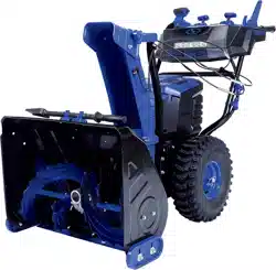
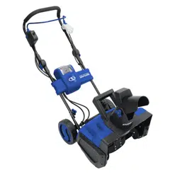
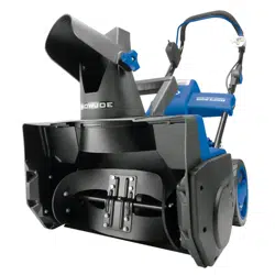
Read the owner’s manual and safety rules carefully before operating your cordless snow blower. Compare the illustration below to the actual unit in order to familiarize yourself with the location of the various controls and adjustments. Save this manual for future reference.

|
1. Auger trigger
2. Safety switch
3. Handle grips (2)
4. Drive trigger
5. Control panel
6. Upper handle assembly
7. Battery compartment cover
8. Handle knob + bolt (4)
9. Lower handle
10. Battery compartment
11. Wheels (2)
12. Auger housing
13. Skid shoes (2)
14. Auger
15. Scraper blade
16. Auger gearcase
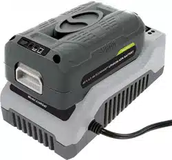
17. Charger plug
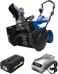
18. iON100V-RCH battery quick charger
19. iON100V-5AMP lithium-iON batteries (2)
20. Battery indicator
|
|
21. Push button for battery indicator
22. Battery handle
23. 0.35 watt LED light
24. Chute clean-out tool
25. Mounting clip
26. Discharge chute
27. Chute deflector knobs (2)
28. Chute deflector
29. Battery releasing buttons (2)
30. LED window
31. 13 mm open end wrench (with 10 mm end)
32. 12 mm open end wrench (with 10 mm end)
33. Auger speed control lever
34. LED switch
35. Reverse button
36. Reverse indicator LED
37. Drive speed lever
38. Discharge chute lock button
39. Discharge chute control lever
|
NOTE!
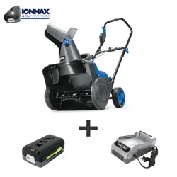
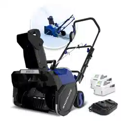
The snow blower can only be powered by two 100V 5.0 Ah batteries (included). Do not use batteries with lower capacity, which will be overheated easily due to the high working current of this machine.
Battery Pack Operation
This equipment is powered by two iON100V-5AMP lithiumion batteries. The battery packs are completely closed and maintenance free.
NOTE
The snow blower can only be powered by two 100 V 5.0 Ah batteries (included). Do not use batteries with lower capacity, which will be overheated easily due to the high working current of this machine.
Battery Charge Level Indicator
The battery packs are equipped with a push button for checking the charge level. Simply press the push button to read off the battery charge level from the LEDs of the battery indicator (Fig. 1):

• All 4 level monitoring LEDs are lit: Battery charge level is high.
• 3 level monitoring LEDs are lit: Battery charge level is decreasing.
• 2 level monitoring LEDs are lit: Battery charge level is decreasing. Stop work as soon as possible.
• 1 level monitoring LED is lit: Battery is flat. Stop work IMMEDIATELY and charge the battery. Otherwise the battery’s service life will be greatly shortened.

NOTE: If the charge level button does not appear to be working, place the battery pack on the charger and charge as needed.
NOTE: Immediately after using the battery pack, the charge level button may display a lower charge than it will if checked a few minutes later. The battery cells “recover” some of their charge after resting.
USB Charging Port
The iON100V-5AMP lithium-iON battery is equipped with 2 USB charging ports, which can provide 5 V power for most smart phones, tablets, wearables and other USB devices.
To charge with the battery, connect a USB cable that came with your selected electronic device to one of the USB ports under the handle of the iON100V-5AMP battery pack and to your device. The charging process will start immediately (Fig. 2).

NOTE: If you experience any issues with charging your particular device, ensure that the battery pack is fully charged.
WARNING! Make sure the battery’s USB ports are not contaminated with lint or other debris. Use a canned-air type of product periodically to ensure that the port openings are clear.
LED light
The iON100V-5AMP battery is equipped with a 0.35 watt LED light located on the handle, which is good for camping and emergency illumination. To turn on the LED light, open the carry handle, and press the battery push button twice in a row. To turn off the LED light, press the battery push button twice again (Fig. 3).

Charger Operation
WARNING! Charge only the iON100V-5AMP lithium-ion battery packs in compatible iON100V-RCH battery charger. Other types of batteries may cause personal injury and damage.
To reduce the risk of electric shock, do not allow water to flow into the charger's AC/DC plug.
When to Charge the iON100V-5AMP Lithium-Ion Batteries
NOTE: The iON100V-5AMP lithium-ion battery packs do not develop a "memory" when charged after only a partial discharge. Therefore, it is not necessary to run down the battery packs before charging.
• Use the battery charge indicator lights to determine when to charge your iON100V-5AMP lithium-ion battery packs.
• You can "top-off" your battery packs' charge before starting a big job or after a long day of use.
Charging the Battery Packs
1. Flip open the battery compartment cover, push the battery releasing buttons to release the battery packs. Pull the batteries out of the equipment (Fig. 4).

2. Check that the mains voltage is the same as that marked on the rating plate of the battery charger. Then, insert the charger's plug into the electrical wall outlet. When you plug in the charger, the red light will illuminate steadily (Fig. 5).

CAUTION! Charger iON100V-RCH is rated for 100 –120 volt AC only. DO NOT plug the charger into any outlet that will provide power with a higher voltage. Over voltage charging will be harmful to both the battery and charger, and may cause the charger to burn out.
3. Place one of the battery packs into the charger by sliding the pack as shown until it clicks into the position. When the battery is inserted properly, the green light will slowly flash to indicate that the battery is charging. The red light will turn off. You will also hear a fan sound (Fig. 6).
4. When the green light stays on, the battery is fully charged (Fig. 6).

NOTE: If the green light is off while the red light flashes slowly, this indicates a temperature abnormality (i.e. that the battery pack is too hot). If the green light is off while the red light flashes rapidly, this indicates there's something wrong with the charger or the battery. Wait for a while and try to reinsert the battery into the charger. If the situation still persists, contact Snow Joe ® + Sun Joe ® customer service at 1-866-SNOWJOE (1-866-766-9563).

5. A fully discharged iON100V-5AMP battery pack with an internal temperature in the normal range will fully charge in 1 hour 40 minutes (between 32ºF/0ºC and 104ºF/40ºC). Heavily discharged battery packs may take longer to charge completely.
6. When charging is complete, remove the battery from the charger by pulling the battery backward to unlock it from the charger (Fig. 7).

7. Repeat the above operations to charge the other battery.
8. Timely recharging of the batteries will help prolong the batteries' life. You must recharge the battery packs when you notice a drop in the equipment's power.
IMPORTANT! Never allow the battery packs to become fully discharged as this will cause irreversible damage to the batteries.
Charger Light Indicator Table
Use the table below to determine charger light patterns and possible causes. For all other issues, contact Snow Joe ® + Sun Joe ® customer service center at 1-866-SNOWJOE (1-866-766-9563).
|
Indication
|
Possible Cause (Solution)
|
|
• Red Light – Steady
• Green Light – Off
|
• No load charging – There's no battery inserted in the charger.
|
|
• Red Light – Off
• Green Light – Slowly flashes
|
• Normal charging – The battery is being charged.
|
|
• Red Light – Off
• Green Light – Steady
|
• Fully charged – The battery is fully charged and the charging process is finished.
|
|
• Red Light – Off
• Green Light – Rapidly flashes
|
• Discharged – The battery is heavily discharged. It may take longer time for charging.
|
|
• Red Light – Slowly flashes
• Green Light – Off
|
• Temperature abnormal – Charging process will start when battery returns to normal temperature.
|
|
• Red Light – Rapidly flashes
• Green Light – Off
|
• Over current charging – The current coming through the charger is greater than what the charger can support. Stop charging as soon as possible.
• Abnormal performance – Something is wrong with the battery or the charger. Contact Snow Joe ®+ Sun Joe ®customer service at 1-866-SNOWJOE (1-866-766-9563).
|
Assembly
WARNING! To avoid serious personal injury, read and understand all safety instructions provided.
WARNING! Unpacking and assembly should be completed on a flat and stable surface, with adequate space for moving the machine and its packaging.
Tools and supplies required:
• Open end wrench (included)
• Tire gauge
Assembling the Handles
1. Slightly spread the upper handle assembly down over the lower handle until it fit in the position (Fig. 8).

2. Adjust upper handle assembly to the optimal position by aligning the double bolt holes at the desired height. Secure the connection using the 4 handle knobs and bolts, and tighten on each side (Fig. 9).

Discharge Chute Assembly
1. Place the discharge chute assembly onto the gear plate, and push down until the chute is flush and flat against the housing (Fig. 10).

2. With the holes on the discharge chute pole aligned with the holes on the housing, use the 12 mm open end wrench to secure the 2 chute bolts with the discharge chute assembly (Fig. 11).

3. Clip the cord clip onto the lower handle frame, insert the discharge chute cable into the cord clip (Fig. 12).

Controls + Features
WARNING! AVOID INJURY. Read and understand the entire safety section before proceeding.
Snow blower controls and features are described below and illustrated in Fig. 13.
Control Panel (Fig. 13)

1. Auger speed control lever – The auger rotation speed can be increased from 116 rpm to 143 rpm by pushing the auger speed control lever forward.
2. LED switch – Press to utilize the LED lights located on the front panel for nighttime snow removal.
3. Reverse button – Press reverse button to enter the snow blower in reverse mode. The reverse indicator LED will light up to indicate the reverse mode is activated.
4. Drive speed control lever – Use the drive speed control lever to control the marching speed of the machine. When machine is marching, push the lever forward to increase the speed, pull it back to reduce the speed.
5. Chute control lever – The chute control lever can be used to adjust the chute direction up to 180 degree, as well as to lower/raise the chute deflector.
Adjust the discharge chute direction by pulling backwards or pushing forwards the chute control lever until the chute has rotated into the desired position (Fig. 14).

To adjust the chute deflector, keep pressing the discharge chute lock button and at the same time push down or raise up the chute control lever (Fig. 15).

NOTE: ALWAYS position discharge chute deflector at a safe angle before engaging the auger.
DO NOT throw snow any higher than necessary.
WARNING! NEVER direct the snow discharge chute at the operator, at bystanders, at vehicles, or at nearby windows. The discharged snow and foreign objects accidentally picked up and thrown by the snow blower can cause serious damage and personal injury.
Always orient the discharge chute in the opposite direction from where the operator, bystanders, surrounding vehicles, or windows are located.
Auger Trigger (Left-Handle) (Fig. 16)

1. Flip up the safety switch, then squeeze the auger trigger against the left-handle to engage the auger and start snow throwing action.
2. Release auger trigger to stop.
Drive Trigger (Right-Handle) (Fig. 17)
Squeeze the drive trigger against the right-handle to engage the wheel drive for propelling unit. Forward speed will vary according to snow depth and moisture content.

NOTE: When travelling to or from the area to be cleared, press down on the handle grips enough to raise the front of the unit slightly off the surface. Engage the drive trigger without engaging the auger trigger.
Chute Clean-Out Tool
The chute clean-out tool is fastened to the top of housing with a mounting clip (Fig. 18).

WARNING! Hand contact with the rotating impeller is the most common cause of injury associated with snow blowers. Never use your hands to clear a clogged discharge chute. Shut off motor and remain behind handles until all moving parts have stopped before unclogging.
To clear the discharge chute:
1. Release both the auger trigger and the drive trigger.
2. Wait 10 seconds and make sure impeller blades have stopped rotating.
3. Remove the clean-out tool from the mounting clip which secures it to the top of the auger housing.
4. Use the shovel-shaped end of the clean-out tool to dislodge and scoop any snow and ice which has formed in and near the discharge chute.
5. Refasten the clean-out tool to mounting clip on the top of the auger housing, flip up the safety switch and restart the snow blower’s motor.
While standing in the operator’s position (behind the snow blower), engage the auger trigger for a few seconds to clear any remaining snow and ice from the discharge chute.
Scraper Blade
The scraper blade allows the back of the housing to keep better contact with the surface being cleared. It also prevents damage to the housing from normal use.
IMPORTANT! DO NOT allow scraper blade to wear too far or auger/impeller housing will become damaged.
Skid Shoes
The skid shoes control the distance between the scraper blade and the ground. Adjust skid shoes equally to keep blade level with the ground.
Position the skid shoes based on surface conditions. Adjust upward for hard-packed snow. Adjust downward when operating on gravel or crushed rock surfaces.
WARNING! It is not recommended that you operate this snow blower on gravel as it can easily pick up and throw loose gravel, causing personal injury or damage to the snow blower and surrounding property.
1. For close snow removal on a smooth surface, raise skid shoes higher on the auger housing. Allow 1/8 in. (3 mm) between scraper blade and hard, smooth surface(s).
2. Use a middle or lower position when the area to be cleared is uneven, such as a gravel driveway. Allow 1-1/4 in. (30 mm) between scraper blade and uneven or gravel surfaces.
NOTE: If you choose to operate the snow blower on a gravel surface, keep the skid shoes in position for maximum clearance between the ground and the scraper blade.
To adjust the skid shoes:
3. Use the 13 mm open end wrench to loosen the 4 hex nuts (2 on each side). Move skid shoes to desired position (Fig. 19).

4. Make certain the entire bottom surface of skid shoes is against the ground to avoid uneven wear on the skid shoes.
5. Retighten hex nuts securely.
Pre-Start
1. Charge batteries – See Charger Operation section on page 10.
2. Check function of triggers – If triggers cannot engage or disengage properly, adjust or repair before operation.
3. Check Skid Shoes – Check and adjust skid shoes.
Emergency Stop
Immediately release both triggers to stop unit in an emergency. Wait for all rotating parts to stop before leaving operator’s position.
Operation
Warning! Failure to follow instructions could result in personal injury and/or damage to snow blower. DO NOT attempt to start your snow blower at this time. Read entire operator manual first.
See page 12 for all controls and features.
WARNING! Keep the area to be cleared free of stones, toys or other foreign objects that the rotor blades might pick up and throw. Such items could be covered by snow and are easy to overlook, so be sure to conduct a thorough inspection of the area before beginning work.
Starting the Machine
IMPORTANT! Make sure both triggers are released before inserting the battery packs.
1. Open the battery compartment cover and slide two battery packs down until they both click and lock into position (Fig. 20). Close the cover.

2. Flip up the safety switch, then squeeze the auger trigger against the left-handle (Fig. 21). The auger will start rotating and plowing snow.

NOTE: Auger trigger should be engaged before drive trigger when throwing snow.
3. Use the auger speed control lever to set a comfortable plowing speed (Fig. 22).

IMPORTANT! DO NOT overload unit capacity by attempting to clear snow at too fast a rate. Use slow speed to clear deep or hard packed snow.
4. Squeeze drive trigger against the right-handle and the snow blower will move (Fig. 23). When the blower is moving steadily, you can release the drive trigger while keep the auger trigger squeezed to maintain the snow blower's movement. Release the auger trigger and both the drive motion and plow motion will stop.

5. Use the drive speed control lever, adjust the speed for a comfortable pace (Fig. 24).

IMPORTANT! Drive speed can be changed the snow blower.
Stopping the Machine
1. Release the auger trigger. Drive motor and auger will both stop (Fig. 25).
2. Wait for all moving parts to come to a complete stop.
3. Remove the batteries.

Reverse Traveling
Be careful when moving backward with the snow blower. Always look down and behind before backing up. For safety reasons, the machine cannot throw snow when moving backward. When auger trigger is activated during reverse travelling, the machine will exit the reverse mode and stop.
1. Before backing up, stop the machine by release both triggers and wait until all movement come to a complete stop.
2. Press the reverse button, the reverse indicator LED will light up to indicate that the machine is in reverse mode (Fig. 26).
3. Squeeze drive trigger against the right-handle and the snow blower will move backward (Fig. 26).

4. During backing up, pay attention not to squeeze the auger trigger. The snow blower will stop if auger is triggered during back up. If this happens, release both triggers and press the reverse button again to restart backing up.
NOTE: When the reverse button is pressed, the reverse mode is activated for 15 seconds. If the drive trigger is not squeezed within 15 seconds, the snow blower will exit the reverse mode.
Operating Tips
WARNING! Foreign objects, such as rocks, broken glass, nails, wire, or string, can be picked up and thrown by the snow blower, causing serious personal injury. Remove all foreign objects from the area to be plowed before operating the snow blower.
Snow is best removed as soon as possible after snow fall.
1. Keep the area of operation free of foreign objects that can become thrown by the rotor blades. Perform a thorough inspection of the area since some objects may be hidden from view by surrounding snow. If the snow blower hits an obstruction or picks up a foreign object during use, stop the snow blower, remove the batteries, remove the obstruction, and inspect the unit for damage. Repair or replace any damaged part before restarting and operating the unit.
2. Keep children, pets, and bystanders away from the area of operation. Be aware that the normal noise of the machine when turned on may make it difficult for you to hear approaching people.
3. For larger areas, a definite pattern of operation is required to thoroughly clean an area of snow. These patterns will avoid throwing snow in unwanted places, a well as eliminate the need for a second removal of snow (Fig. 27).
Pattern A: Throw the snow to the right or left side where it is possible. For areas such as a long driveway, it is advantageous to start in the middle. Plow from one end to the other, throwing snow to both sides.
Pattern B: If the snow can only be thrown to one side of the area to be cleared, start on the opposite side.

4. Note the wind direction. If possible, move in the same direction as the wind so that the snow is not thrown against the wind (and thus back into your face and on the just cleared path).
5. Do not push the snow blower with excessive force. Do not exceed the unit's intake or throw rate.
6. Some parts of the snow blower may freeze under extreme temperature conditions. Do not attempt to operate the snow blower with frozen parts. If the parts freeze while the snow blower is in use, stop the snow blower, remove the batteries, and inspect for frozen parts. Free all parts before restarting or operating the snow blower. Never force controls that have frozen.
Maintenance
To order genuine replacement parts or accessories for the Snow Joe ® iON100V-24SB cordless snow blower, please visit snowjoe or contact the Snow Joe ® + Sun Joe ® customer service center at 1-866-SNOWJOE (1-866-766-9563).
WARNING! Make sure to turn off the snow blower and remove the batteries before performing any maintenance task on your snow blower.
General Maintenance Tips
1. Do not attempt to repair the machine unless you have the proper tools and instructions for disassembly and repair of the machine.
2. Check bolts and screws at frequent intervals for proper tightness to ensure that the equipment is in safe working condition.
3. After each snow removal session, run the snow blower for a few minutes to prevent the collector/impeller from freezing. Shut off the motor, wait for all revolving parts to stop completely, remove the batteries and wipe residual ice and snow off the unit.
Proper Care for Battery + Charger
WARNING! To reduce the risk of injury, always unplug the charger and remove the battery pack from the charger before performing any maintenance task. Never disassemble the battery packs or charger. Contact your Snow Joe ® + Sun Joe ® dealer or the Snow Joe ® + Sun Joe ® customer service center for ALL repairs.
1. To reduce the risk of injury and damage, never immerse your battery packs or charger in liquid or allow any liquid to flow inside these components.
2. Clean out dust and debris from charger vents and electrical contacts by blowing with compressed air.
3. Use only mild soap on a damp cloth to clean the battery packs and charger, keeping away from all electrical contacts. Certain cleaning agents and solvents are harmful to plastics and other insulated parts. Some of these include gasoline, turpentine, lacquer thinner, paint thinner, chlorinated cleaning solvents, ammonia and household detergents containing ammonia. Never use flammable or combustible solvents around battery packs, battery chargers or tools.
4. The iON100V-RCH lithium-ion battery charger has no serviceable parts.
Check Tire Pressure
WARNING! Under any circumstance do not exceed manufacturer’s recommended PSI. Equal tire pressure should be maintained at all times for performance purposes. Excessive pressure may cause tire/rim assembly to burst with force sufficient to cause serious injury. Refer to sidewall of tire for recommended pressure.
The tires are over-inflated for shipping purposes. Check the tire pressure before operating the snow blower and deflate (or inflate) the tires as necessary.
Manufacturer's Recommended Tire Pressure 20 PSI
CAUTION! Avoid injury. Explosive separation of tire and rim parts is possible when they are serviced incorrectly:
• Do not attempt to mount a tire without proper equipment and experience to perform the job.
• Do not inflate the tires above the recommended pressure.
• Do not weld or heat a wheel and tire assembly. Heat can cause an increase in air pressure resulting in an explosion. Welding can structurally weaken or deform the wheel.
• Do not stand in front or over the tire assembly when inflating. Use a clip-on chuck and extension hose long enough to allow you to stand to one side.
Replacing Skid Shoes
The skid shoes on the bottom of the snow blower are subject to wear. They should be checked periodically and replaced when necessary.
To replace skid shoes:
1. Position unit on a hard, flat, smooth level surface.
2. Using the 13 mm open end wrench, remove the 4 hex nuts (2 on each side), washers and bolts which secure the skid shoes to the snow blower (Fig. 28).

3. Install the new skid shoes by tightening the 4 sets of hex nuts, washers and bolts on both sides, but leave the skid shoes free to move for height adjustment.
4. Slide skid shoes to flat surface. Allow 1/8 in. (3 mm) between scraper blade and hard smooth surface. Allow 1-1/4 in. (30 mm) between scraper blade and uneven or gravel surfaces.
NOTE: Keep housing level by adjusting skid shoes equally. 5. Retighten the 4 sets of hex nuts and bolts on both sides.
Replacing Scraper Blade

IMPORTANT! Damage to auger/impeller housing will result if the scraper blade wears down too far.
To replace scraper blade:
1. Position the unit on a hard, flat, smooth level surface.
2. Detach the worn scraper blade from the snow blower by removing the 5 hex nuts and bolts that hold it in place (Fig. 29).
3. Install the new scraper blade and fasten it securely to the snow blower with 5 hex nuts and bolts.
Replacing Shear Bolts

The auger is secured to the auger shaft with shear bolts and nuts. If the auger should strike a foreign object or ice jam, the snow blower is designed so that the bolts may shear. If the auger will not turn, check to see if the bolts have sheared.
CAUTION! Use only manufacturer's recommended shear bolts for replacement. Use of any other type of shear bolts may result in severe damage to unit and may void the warranty. Call the Snow Joe ® + Sun Joe ® customer service center at 1-866-SNOWJOE (1-866-766-9563) for assistance.
Occasionally a foreign object may enter the auger/impeller housing and jam the auger, breaking the shear bolts which secure the auger to the shaft. This allows the auger to turn freely on the shaft which may help prevent damage to the gearcase and its components.
WARNING! Always turn off the snow blower’s motor and remove the batteries prior to replacing shear bolts.
1. Align shear bolt holes in auger with shear bolt holes in the shaft.
2. Drive shear bolt through hole. If shear bolt was broken this will drive remaining part from shaft (Fig. 30).
3. Secure shear bolts with the nuts, with the 10 mm end of either open end wrench (Fig. 30).
Replacing Auger Blades
1. Disassemble the auger and impeller assembly by removing the bolts from the sides of the auger housing with the 12 mm open end wrench (Fig. 31), and pull out the auger and impeller assembly (Fig. 32).

2. Using the 12 mm open end wrench, remove the bolts that used to secure the auger bearings, then remove the auger bearings on both sides (Fig. 33).

3. Remove 2 set of shear bolts and nuts from the auger blades with the 12 mm end of either open end wrench. The auger blades should be able to be removed from the auger shaft (Figs. 34 – 35).

4. Install the replacement auger blades by following the above steps in reverse order.
Replacing Impeller
1. To remove the impeller, disassemble the auger and impeller assembly by removing the bolts from the sides of the auger housing with the 12 mm open end wrench (Fig. 31), and pull out the auger and impeller assembly (Fig. 32).
2. Disassemble the worn impeller from the impeller shaft by removing the 2 spring pins (Fig. 36).

3. Install the replacement impeller by following the above steps in reverse order.
Lubrication
Auger Shaft
At least once a season, remove the shear bolts from the auger shafts. Spray lubricant inside the shaft and around the bearings at each end of the shaft.
Auger Gearcase
Gearcases are filled to the correct level at the factory. Within first 150 hours of running, no additional lubricant should be required unless there is evidence of leakage.
Any work on the inside structure of auger requires specific experience and special tools. For safety purposes, we recommend you contact an authorized Snow Joe ® + Sun Joe® dealer or call the Snow Joe ® + Sun Joe ® customer service center at 1-866-SNOWJOE (1-866-766-9563).
To fill the gearcase, follow the instruction below every 150 to 200 hours operation:
1. Remove the fill plug with the 10 mm end of either open end wrench. Inject some general low-temperature synthetic grease to filler hole. Replace plug. (Fig. 37).

IMPORTANT! Wipe each fitting clean before and after lubrication. Do not wipe gearcase filler plug; wiping the gearcase filler plug may remove thread sealant and cause leaks.
Storage
1. Examine the cordless snow blower thoroughly for worn, loose or damaged parts. Should you need to repair or replace a part, contact an authorized Snow Joe ® + Sun Joe ® dealer or call the Snow Joe ® + Sun Joe® customer service center at 1-866-SNOWJOE (1-866-766-9563) for assistance.
2. Clean the snow blower before storing or transporting. Be sure to secure the unit while transporting.
3. Remove the battery packs from the cordless snow blower before storing.
4. Store the cordless snow blower indoors in a locked, dry place out of the reach of children to prevent unauthorized use or damage.
Battery + Charger Off-Season Storage
1. Do not expose your battery packs or charger to water, rain or allow them to get wet. This could permanently damage the charger and the battery packs. Do not use oil or solvents to clean or lubricate your battery packs as the plastic casing can become brittle and crack, causing a serious risk of injury.
2. Store the battery packs and charger at room temperature away from moisture. Do not store in damp locations where corrosion of terminals may occur. As with other battery pack types, permanent capacity loss can result if the pack is stored for long periods of time at high temperatures (over 120ºF/49ºC).
3. iON100V SERIES battery packs maintain their charge during storage longer than other battery pack types. As a general practice, it is best to unplug the battery charger and remove the battery pack when they are not in use. Recharge the battery packs every 6 months to 50% capacity (2 lights on) during off-season storage to maintain optimal battery performance.
Always dispose of your battery packs according to federal, state, and local regulations. Contact a recycling agency in your area for recycling locations.
CAUTION! Even discharged battery packs contain some energy. Before disposing, use electrical tape to cover the terminals to prevent the battery pack from shorting, which could cause a fire or explosion.
WARNING! To reduce the risk of injury or explosion, never burn or incinerate a battery pack even if it is damaged, dead or completely discharged. When burned, toxic fumes and materials are emitted into the surrounding atmosphere.
1. Batteries vary according to device. Consult your manual for specific information.
2. Install only new batteries of the same type in your product (where applicable).
3. Failure to insert batteries in the correct polarity, as indicated in the battery compartment or manual, may shorten the life of the batteries or cause batteries to leak.
4. Do not mix old and new batteries.
5. Do not mix Alkaline, Standard (Carbon-Zinc) or Rechargeable (Nickel Cadmium, Nickel Metal Hydride, or Lithium-Ion) batteries.
6. Do not dispose of batteries in fire.
7. Batteries should be recycled or disposed of as per state and local guidelines.