Loading ...
Loading ...
Loading ...
8
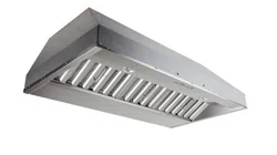
8. REMOVE KNOCK-OUT OPENING (CP55IQ AND CP57IQT SERIES ONLY)
From inside the power pack, remove the wiring box cover by removing 2 retaining screws and
set aside. Punch out the electrical knockout hole on top of the power pack. Install the wire clamp
(included in parts bag).
9. INSTALL THE 8” ADAPTER/DAMPER (CP55IQ SERIES ONLY)
Using 4 no. 8 x 3/8” screws from parts bag, assemble the adapter/damper on the top of the power
pack. To ensure proper opening of the dampers, remove shipping tape if present. Seal all joints
with metal foil duct tape to eliminate air leaks.
HR0027
HJ0016
MOUNTING SCREW LOCATIONS
10. INSTALL THE 10” ADAPTER (CP57IQT SERIES ONLY)
Using 2 no. 8 x 3/8” screws from parts bag, assemble the adapter on the top of the power pack.
Seal all joints with metal foil duct tape to eliminate air leaks.
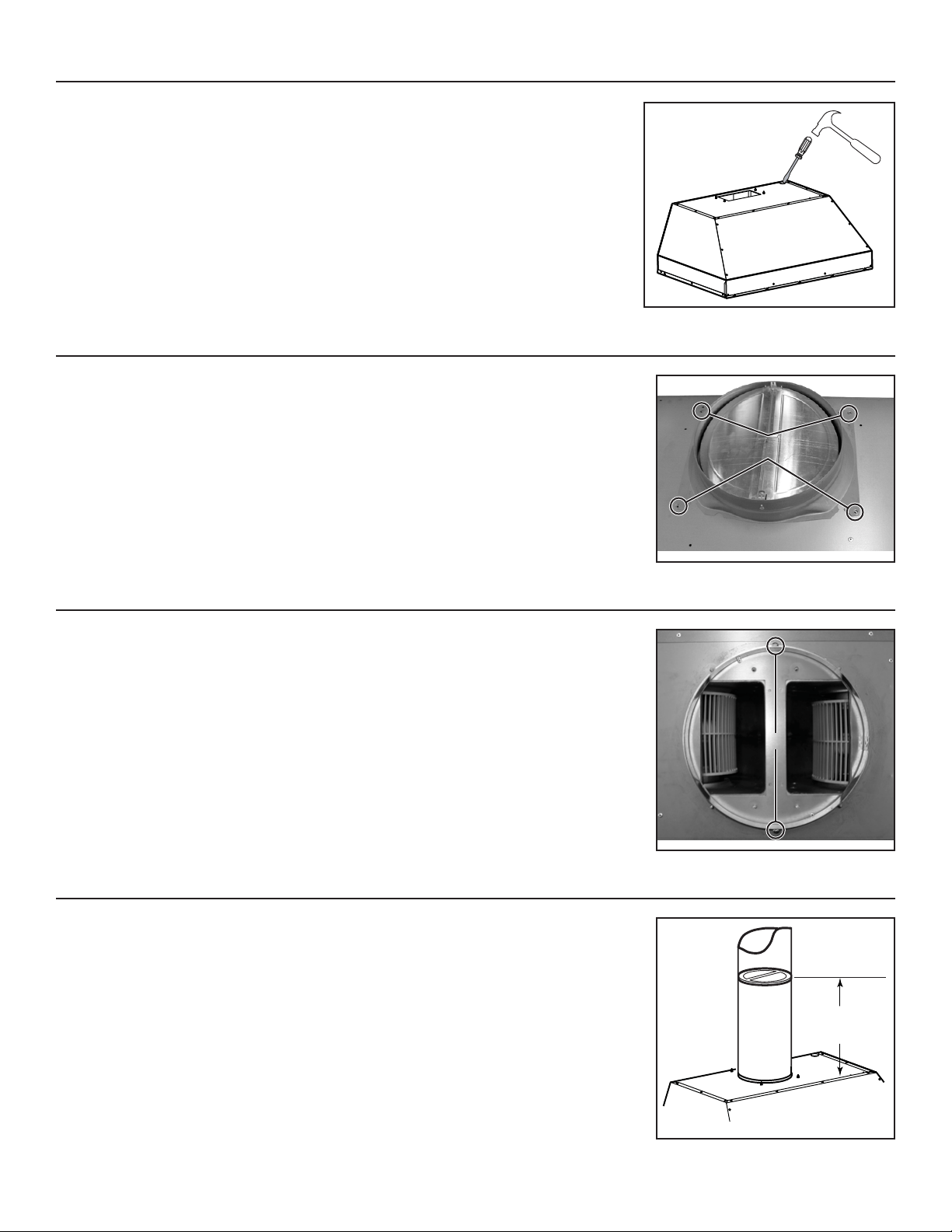
NOTE: For a non-ducted installation, do not install the 10” in-line damper.
Install 10” in-line damper inside the vertical ductwork that will be attached to power pack. Do not
install in a horizontal ductwork or it will not open and close properly. Remove shipping tape if
present. Secure the damper to the duct with 3 no. 8 sheet metal screws (not provided). Ensure
damper opens and closes freely. Seal all joints with metal foil duct tape to eliminate air leaks.
10" min.
recommended
HJ0073A
11. INSTALL THE 10” IN-LINE DAMPER (CP57IQT AND CP57E SERIES, DUCTED INSTALLATION ONLY)
HJ0026
MOUNTING SCREW LOCATIONS
Loading ...
Loading ...
Loading ...