OPERATING INSTRUCTION MANUAL Electric Inset Fire
General
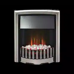
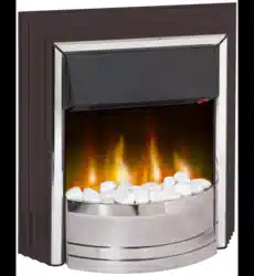
Unpack the heater carefully and retain the packaging for possible future use, in the event of moving or returning the fire to your supplier. Loose coals (and or pebbles) are packed separately within the carton. When the heater is assembled the coals (or pebbles) are placed on top of the fuel bed.
The heater is designed for use inset into a 407mm (16") or 457mm (18") wide by 559mm (22") high fireplace opening see also section ‘Installation in a Fireplace Opening’.
A 2kW fan heater discreetly positioned in the canopy of the fire provides heating in cold weather. Switching allows half or full heat. A minimum distance of 1 metre (39") must be maintained between the front of the heater and any surrounding furniture, overhanging curtains or other obstructions.
To reduce heat loss and to prevent any chimney up draught affecting the operation of your inset fire we recommend that the chimney flue is sealed off.
Before connecting the heater check that the supply voltage is the same as that stated on the heater. Please note: Used in an environment where background noise is very low, it may be possible to hear a sound which is related to the operation of the flame effect. This is normal and should not be a cause for concern.
Electrical
WARNING – THIS APPLIANCE MUST BE EARTHED. This heater must be used on an AC ~ supply only and the voltage marked on the heater must correspond to the supply voltage. Before switching on, please read the safety warnings and operating instructions.
Surround Spacer
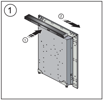
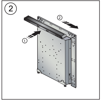
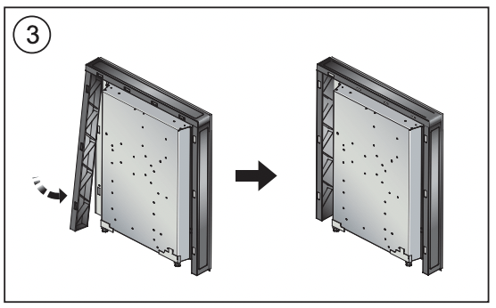
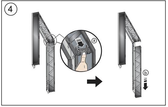
In the event that your fireplace is not deep enough for your electric fire, all models have been supplied with a spacer which allows the fire to be freestanding. If a plastic spacer is not already fixed to your fire, please follow the steps in Fig. 1 - 3 below to assemble your spacer. See Fig. 4 to disassemble this spacer assembly. If a metal spacer is already fixed to your fire and is not required, remove the four screws to allow the fire to be fully inset.
Installation in a Fireplace Opening
At the rear of the fire, two adjustable feet are provided for levelling the fire where the base of the fireplace opening is raised above the level of the hearth. Adjust the foot bracket height by removing the 2 screws, reposition the foot bracket and refix with screws. The surround spacer may be removed (four screws) to allow the fire to be fully inset. The minimum opening size required for the fire to be fully inset is 392mm wide, 550mm high and 70mm deep. Alternatively the surround spacer may be left on and positioned freestanding against a wall
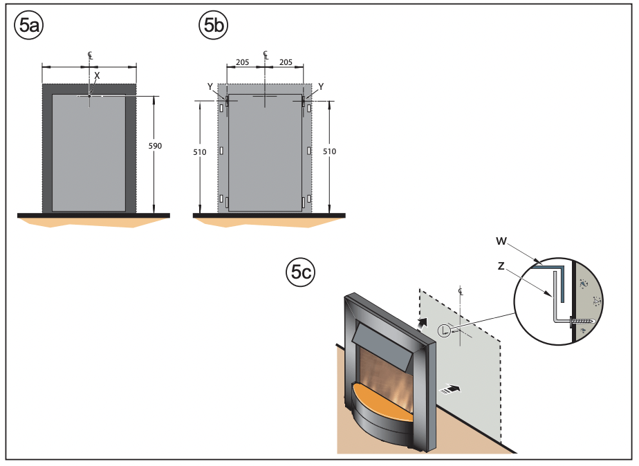
To ensure the appliance stability, the fire is supplied with a hook and rawl plug. The rawl plug supplied is suitable for use in block walls (special fasteners required on stud walls). Spacer attached - Fig. 5a: In the event that the fire is to be positioned against a wall with the surround spacer attached, the fixing position of the hook is indicated by ‘X’ in Fig. 5a. When the hook is securely fastened, centre the fire to the hook. Lift the fire up and over the hook (see ‘z’ in Fig. 5c) ensuring that the surround spacer (see ‘w’ in Fig. 5c) engages the hook.
No Spacer attached - Fig. 5b: In the event that the fire is to be positioned fully inset without the surround spacer, the fixing position of the hook is indicated by ‘Y’ (the hook can be positioned on either side of the fire) in Fig. 5b. When the hook is securely fastened, position the top slot on the fire (see Fig. 5b) alongside the hook, lift the fire up and over the hook so that the top slot on the fire engages the hook.
Operation
The unique flame effect may be enjoyed whether or not the heating elements are in operation.
Controls
The heater controls are located on the canopy. (On some models, raise the canopy cover to access the controls).
Three switches provide a choice of heat settings. (On some models, an adjustable thermostat is fitted, enabling the temperature to be controlled by adjusting the setting accordingly).
A switch is in the ON position when the red indicator mark on the switch is visible.
Switch 1 - Controls the electricity supply to the heater and the flame effect.
Note: This switch must be in the ON position for the heater to operate.
Switch 2 - Provides 1kw heat output.
Switch 3 - Provides 2kw heat output with switch 2.
Setting the Thermostat (if supplied)
Plug in and set all switches to ON. Turn the thermostat knob to MAX to warm the room rapidly. When the room temperature has reached the desired level, turn the thermostat knob back slowly until the thermostat just clicks off. The heater will then maintain the room temperature at the chosen level.
NOTE – Should your heater fail to come on when the thermostat is at a low setting, this may be due to the room temperature being higher than the thermostat setting.
Maintenance
WARNING – BEFORE UNDERTAKING ANY MAINTENANCE OR CLEANING, REMOVE PLUG OR DISCONNECT FROM THE ELECTRICITY SUPPLY.
Light Emitting Diode
This fire is fitted with LED (Light Emitting Diode) bulbs in place of conventional bulbs. These generate the same light levels as conventional bulbs, but use a fraction of the energy consumed.
Safety cut-out
For your safety, this appliance has been fitted with a thermal cut-out. In the event that the product overheats, the cut-out switches the heat off automatically.
To bring the heat back into operation, remove the cause of the overheating, then unplug or turn off the electrical supply to the heater for up to 10 minutes.
When the heater has cooled sufficiently, re-connect and switch on the heater.
Cleaning
Before commencing cleaning, unplug the heater and allow it to cool.
The surfaces of the heater should be given an occasional wipe over with a dry soft cloth.
Do not use detergents, abrasive cleaning powder or polish on the metal body of the heater.
The glass screen should be cleaned carefully with a chamois leather.
DO NOT use proprietary cleaners.
To remove any accumulation of dust or fluff the soft brush attachment of a vacuum cleaner should occasionally be used to clean the outlet grille of the fan heater located under the canopy.
To clean the fuel effect, remove the coal/pebbles and wash in warm water. The plastic tray should be wiped clean with a damp cloth. When dry replace the coal/pebbles and arrange for best effect.