Loading ...
Loading ...
Loading ...
20GB
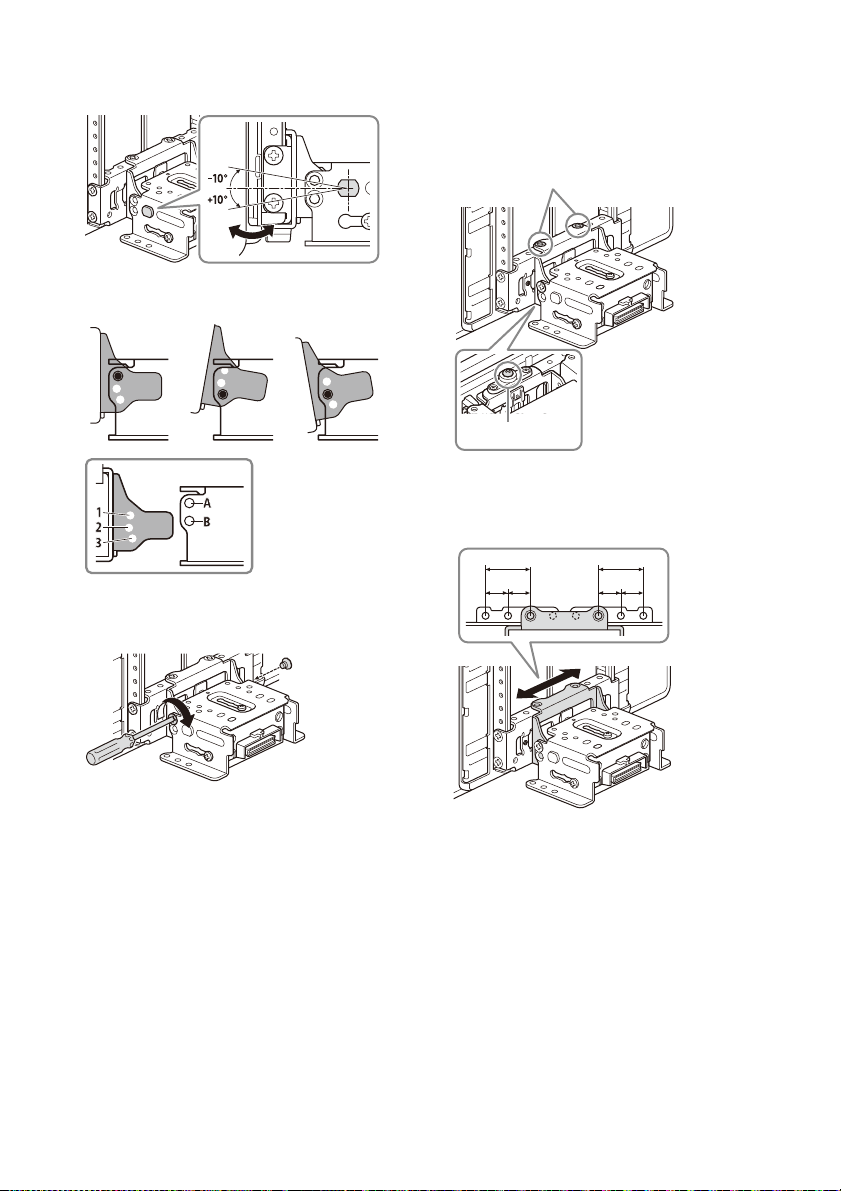
2 Adjust the display angle to decide the
appropriate angle.
Adjustable angle: -10° to +10°, in 3 steps
Screw holes to use:
3 At the desired angle, tighten the 2 screws
through the screw holes (upper or lower)
that match the display angle.
Tighten the screws firmly.
When you tighten a screw, be careful not to
apply too much torque as doing so may damage
the screw (the torque value should be from
1.5 N•m to 2.0 N•m).
Adjusting the width of the display
position
1
Remove the 2 pre-installed screws on the
top side and loosen the 1 installed screw on
the bottom side for left/right adjustment.
2 Slide the connector bracket to the left or
right to decide the appropriate position.
Adjustable left/right: within 25 mm (1 in) (), in
5 steps, in 12.5 mm (1/2 in) pitch ().
Be sure to adjust the appropriate position with
the connector bracket in the same state as the
illustration above.
If the connector bracket is upside down, it will be
stuck by the screw on the bottom side and will
not move left or right.
0° (1 – A) -10° (3 – B) +10° (2 – B)
Pre-installed screws
Installed screw
ɸ
ɹɹ
ɸ
ɹɹ
Loading ...
Loading ...
Loading ...