Loading ...
Loading ...
Loading ...
32
Single Zone Mega and Mega 115V Wall Mounted Installation Manual
'XHWRRXUSROLF\RIFRQWLQXRXVSURGXFWLQQRYDWLRQVRPHVSHFL¿FDWLRQVPD\FKDQJHZLWKRXWQRWL¿FDWLRQ
©
/*(OHFWURQLFV86$,QF(QJOHZRRG&OLIIV1-$OOULJKWVUHVHUYHG³/*´LVDUHJLVWHUHGWUDGHPDUNRI/*&RUS
REFRIGERANT SYSTEM ENGINEERING
Pipe Sleeves at Penetrations
LG recommends that all pipe penetrations through walls, floors, and pipes buried underground be properly insulated and routed through an
appropriate wall sleeve of sufficient size to prevent compression of refrigerant pipe insulation and free movement of the pipe within the
sleeve. Use 4”+ curved sheet metal saddles between the bottom surface of the pipe and the bottom surface of the penetration.
Figure 35: Pipe Sleeve Options.
Diameter of penetrations must be determined by pipe diameter plus the thickness of the insulation.
Underground Refrigerant Piping
Refrigerant pipe installed underground must be routed inside a vapor tight protective
sleeve to prevent insulation deterioration and water infiltration. Refrigerant pipe in-
stalled inside underground casing must be continuous without any joints. Underground
refrigerant pipe must be located at a level below the frost line.
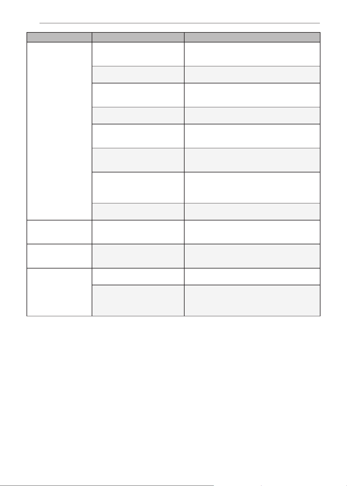
Table 16: Utility Conduit Sizes.
1
OD pipe diameter in inches; Values in parenthesis () indicate OD of pipe with insulation jacket.
2
Diameter of pipe with insulation. Thickness of pipe insulation is typical. Actual required thickness will
vary based on surrounding ambient conditions and must be calculated and specified by the design
engineer.
3
Insulation thickness (value in parenthesis) = 3/8 inch.
4
Insulation thickness (value in parenthesis) = 1 inch.
5
Insulation thickness (value in parenthesis) = 3/4 inch.
Liquid Pipe
1
Vapor Pipe
1
3/8 (2.0
2,5
) 1/2 (2.0
2,5
) 5/8 (2-1/8
2,5
) 3/4 (2-1/4
2,5
)
1/4 (1.0)
3
4444
3/8 (1-1/8)
3
4445
1/2 (1-1/2)
4
5555
5/8 (1-5/8)
4
5555
3/4 (1-3/4)
4
5555
Figure 36: Typical Arrangement of Single Zone Refrig-
erant Pipe and Cable(s) in a Utility Conduit.
Table 17: Heat Pump Unit Refrigerant Pipe Connections (All Flared
Type).
Model
Liquid Conn.
(inches)
Vapor Conn.
(inches)
LSU090HEV2, LSU120HEV2,
LSU90HXV2, LSU120HXV2
1/4 3/8
LSU180HEV2, LSU240HEV2 1/4 1/2
Provide expansion joints in long pipe segments and place in an accessi-
ble conduit box for inspection. Use galvanized curved sheet metal sad-
dles at all mounting points. Pipe must be allowed to move freely linearly.
Vapor Line
Liquid Line
Min. 14 Gauge
Cable
Power/Communication
Pi
p
e Sleeve
Insulation Material
Insulation
Material
Loading ...
Loading ...
Loading ...