INSTRUCTION MANUAL
- for the -
TWIN STIM
®
PLUS OTC

- 2 -
This manual is valid for the
Twin Stim Plus OTC
This instruction manual is published by Compass Health Brands.
Compass Health Brands reserves the right to improve and amend it at
any time without prior notice. Amendments may however be published
in new editions of this manual.
All Rights Reserved.Rev.V1.0 © 2019
FDA cleared for OTC use
Conformity to safety standards
Compass Health Brands declares that the
device complies with following normative documents:
IEC60601-1, IEC60601-1-2, I EC60601-2-10,
ISO10993-5, ISO10993-10, ISO10993-1

- 3 -
Table of Contents
1. Introduction ........................................4
1.1 General
1.2 Medical Background
1.3 Indication for use
2. Important Safety Precautions and Warnings............6
3. Package Contents .................................13
3.1 Front And Rear Panel
3.2 LCD Display
4. Specification ......................................16
4.1 Technical Information
4.2 Technical Specications (TENS)
4.3 Technical Specications (EMS)
4.4 Waveform Information (TENS)
4.5 Waveform Information (EMS)
5. Instruction For Use.................................20
5.1 Battery
5.2 Using Your Device
5.3 To Set TENS parameters
5.4 To Set EMS parameters
5.5 Check Compliance Meter
5.6 Check/Replace Batteries
6. Cleaning And Storage ..............................30
6.1 Keeping Electrodes Clean
6.2 Storing Device, Electrodes and Lead Wires
7. Troubleshooting ...................................32
8. Disposal ..........................................34
9. Glossary Of Symbols ...............................34
10. Electromagnetic Compatibility (EMC) Tables ..........35
11. Warranty ..........................................40

- 4 -
1. INTRODUCTION
1.1 General
The Twin Stim Plus OTC is a portable electrotherapy device
featuring two therapeutic modes: Transcutaneous Electrical Nerve
Stimulator (TENS) and Neuromuscular Electrical Stimulation (EMS),
which are used for pain relief and electrical muscle stimulation.
The stimulator sends gentle electrical current to underlying nerves
and muscle group via electrodes applied on the skin. The parameters
of device are controlled by the buttons on the front panel. The intensity
level is adjustable according to the needs of patients.
1.2 Medical Background
Explanation of pain
Pain is an unpleasant sensation that can serve a useful purpose by
alerting us to a possible injury or disease. When the body is functioning
normally, pain serves as a warning system that something is not right.
Without pain a person would not know when to avoid danger or seek
medical help. Pain becomes a problem when it continues after treatment
has started or long after an injury is healed.

- 5 -
How TENS Works
There is nothing “magic” about Transcutaneous Electrical Nerve
Stimulation (TENS). TENS is intended to help relieve pain. The TENS
device sends comfortable impulses through the skin to stimulate the
nerve (or nerves) in the treatment area. In many cases, this stimulation
will greatly reduce or eliminate the pain sensation the patient feels. Pain
relief varies by individual patients, mode selected for therapy, and the
type of pain. In many patients, the reduction or elimination of pain lasts
longer than the actual period of stimulation (sometimes as much as three
to four times longer). In others, pain is only modied while stimulation
actually occurs. You may discuss this with your physician or therapist.
How EMS Works
Neuromuscular Electrical Stimulation (EMS) is an internationally
accepted and proven way of treating muscular injuries. It works by
sending electronic pulses to the muscle needing treatment; this causes
the muscle to exercise passively. This device is low frequency and in
conjunction with the square wave pattern allows the stimulation to
work directly on the muscle groups.
The goal of electrical muscle stimulation is to achieve contractions or
vibrations in the muscles. Normal muscular activity is controlled by the
central and peripheral nervous systems, which transmit electrical signals
to the muscles. EMS works similarly but uses an external source (the
stimulator) with electrodes attached to the skin for transmitting electrical
pulses into the body. The pulses stimulate the nerves to send signals to a
specically targeted muscle, which reacts by contracting, just as it does
with normal muscular activity
- 6 -
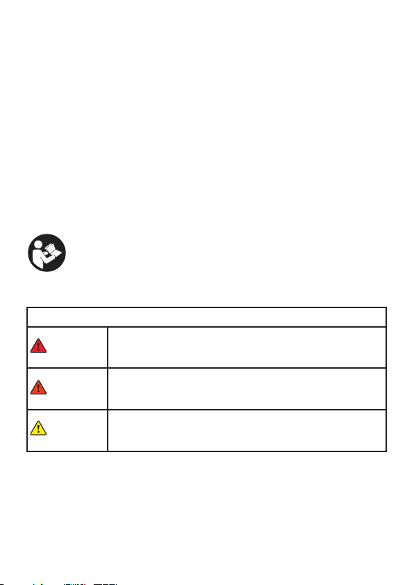
SAFETY SYMBOLS USED IN THIS MANUAL
DANGER
Indicates a potentially hazardous situation which, if not
avoided, could result in death or serious injury.
WARNING
Indicates a potentially hazardous situation which, if not
avoided, could result in serious injury and equipment
damage.
CAUTION
Indicates a potentially hazardous situation which, if not
avoided, may result in minor or moderate injury to the user
or patient or damage to the device or other property.
1.3 Indication for Use
The Twin Stim Plus OTC Stimulator is designed to be used for temporary
relief of pain associated with sore and aching muscles in the shoulder,
waist, back, neck, upper extremities(arm)and lower extremities(leg) due
to strain from exercise or normal household work activities.
And it is to be used for stimulate healthy muscles in order to improve and
facilitate muscle performance.
2. IMPORTANT SAFETY PRECAUTIONS
AND WARNINGS
It is important that you read all the warning and
precautions included in this manual because they are
intended to keep you safe, prevent injury and avoid a
situation that could result in damage to the device.
- 7 -
DANGER
This stimulator must NOT be used in combination with the following medical
devices:
• Internally transplanted electronic medical devices,
such as a pacemaker.
• Electronic life support equipment, such as respirators.
• Electronic medical devices attached to the body,
such as electrocardiographs.
Using this stimulator with other electronic medical devices may cause
erroneous operation of those devices.
WARNING
DO NOT USE THIS DEVICE UNDER THESE CONDITIONS
• Consult with your physician before using this device, because the device
may cause lethal rhythm disturbances in certain susceptible individuals.
• If you have a cardiac pacemaker, implanted debrillator, or other implanted
metallic or electronic device. Such use could cause electric shock, burns,
electrical interference, or death.
• Together with a life-supporting medical electronic device such as an articial
heart or lung or respirator.
• In the presence of electronic monitoring equipment (e.g., cardiac monitors,
ECG alarms), which may not operate properly when the electrical stimulation
device is in use.
• On open wounds or rashes, or over swollen, red, infected, or inamed areas
or skin eruptions (e.g., phlebitis, thrombophlebitis, varicose veins); or on top
of, or in proximity to, cancerous lesions.
• Over areas of skin that lack normal sensation.
• On the opposite sides of your head since the effects of stimulation
of the brain are unknown.
DO NOT USE ON THESE INDIVIDUALS
• Pregnant women, because the safety of electrical stimulation during
pregnancy has not been established.
• Children or infants, because the device has not been evaluated for
pediatric use.
• Persons incapable of expressing their thoughts or intentions.
- 8 -
WARNING (CONTINUED)
DO NOT USE THIS DEVICE DURING THESE ACTIVITIES
• When in the bath or shower
• While sleeping
• While driving, operating machinery, or during any activity in which
electrical stimulation can put you at risk for injury.
PAIN MANAGEMENT WARNINGS
• If you have had medical or physical treatment for your pain, consult with your
physician before using this device.
• If your pain does not improve, becomes seriously chronic or severe, or
continues for more than ve days, stop using the device and consult
with your physician.
• The mere existence of pain functions as a very important warning telling us
that something is wrong. Therefore, if you suffer from any serious illness,
consult your physician in order to conrm that it is advisable for you to use
this TENS & EMS Stimulator.
WARNINGS AND PRECAUTIONS REGARDING THE
ELECTRODES
• Apply electrodes to normal, healthy, dry, clean skin (of adult patients) because
it may otherwise disrupt the healing process.
• If you experience any skin irritation or redness after a session, DO NOT
continue stimulation in that area of the skin.
NEVER APPLY THE ELECTRODES TO:
• The head or any area of the face.
• Any area of the throat because this could cause severe muscle
spasms resulting in closure of the airway, difculty in breathing,
or adverse effects on heart rhythm or blood pressure.
• Both sides of the thorax simultaneously (lateral or front and
back), or across your chest because the introduction of electrical
current may cause rhythm disturbances which could be lethal.

- 9 -
CAUTION
WARNINGS AND PRECAUTIONS REGARDING
THE ELECTRODES
• DO NOT bend or fold because the pad may not function properly. Place
the electrodes onto the plastic lm and then store into the sealed package
when not in use.
• DO NOT apply ointment or any solvent to the electrodes or to your skin
because it will disrupt the electrodes from functioning properly.
• The electrodes are already pre-gelled and will adhere to your skin.
• To avoid damage to the adhesive surface of the electrodes, put the electrodes
only on the skin or on the plastic lm provided.
• Place the electrodes at least 2” apart but no more than 6” apart per channel.
• Make sure the components are connected well and the electrodes are xed
on the part of the body you wish to treat or the therapy may not be effective.
DO NOT USE YOUR ELECTRODES THIS WAY
• Electrodes should NOT touch each other when placed onto your skin.
• DO NOT place on your spine or backbone.
• Pad should NOT touch any metal object, such as a belt buckle or necklace.
• Electrodes should NOT be placed simultaneously on the soles of both feet.
• Electrodes should NOT be placed simultaneously on the calves of both legs.
• DO NOT share electrodes with another person. This may cause a skin irrita-
tion or infection. Electrodes are intended for use by one person.
• DO NOT place or relocate the electrodes while the device is on.
• ALWAYS turn the power off before removing or changing the pad location.
• DO NOT leave electrodes attached to the skin after treatment.

- 10 -
CAUTION (CONTINUED)
CAUTION WHILE USING THE STIMULATOR
• If the stimulator is not functioning properly or you feel discomfort,
immediately stop using the device. If any type of shock or burn should occur,
stop using immediately and consider seeking medical attention (if necessary).
• DO NOT use for any other purpose except for what it is intended for.
• DO NOT insert the electrode plug into any place other than the jack
on the main device.
• DO NOT mix Alkaline and Manganese batteries as this will shorten
the battery life.
• DO NOT pull on the electrode cord during treatment.
• DO NOT use the device while wearing electronic devices such as
watches as this may damage the device.
• DO NOT use near a cell phone as this may cause the stimulator to malfunction.
• DO NOT bend or pull the end of the cord.
• When pulling out the cord from the device, hold the plug and pull.
• Replace the cord when broken or damaged.
• DO NOT throw the batteries into a re. The batteries may explode.
• Dispose of the device, batteries, and components according to applicable
legal regulations. Unlawful disposal may cause environmental pollution.
• The size, shape and type of electrodes may affect the safety and effectiveness
of electrical stimulation.
• The electrical performance characteristics of electrodes may affect the safety
and effectiveness of electrical stimulation.
• Using electrodes that are too small or incorrectly applied, could result in
discomfort or skin burns.

- 11 -
GENERAL PRECAUTIONS
• The long-term effects of electrical stimulation are unknown.
• Apply stimulation to only normal, intact, clean, dry, and healthy skin.
• TENS is NOT effective in treating the original source or cause of the pain,
including headache.
• TENS is NOT a substitute for pain medications and other
pain management therapies.
• TENS devices DO NOT cure disease or injuries.
• TENS is a symptomatic treatment and, as such, suppresses the sensation
of pain that would otherwise serve as a protective mechanism.
• Effectiveness is highly dependent upon patient selection by a practitioner
qualied in the management of pain patients.
• You may experience skin irritation or hypersensitivity due to the electrical
stimulation or electrical conductive medium (gel).
• If you have suspected or diagnosed heart disease, you should follow
precautions recommended by your physician.
• If you have suspected or diagnosed epilepsy, you should follow precautions
recommended by your physician.
• Use caution if you have a tendency to bleed internally, such as following
an injury or fracture stop using the device. If any type of shock or burn should
occur, stop using immediately and seek medical attention (if necessary).
• Consult with your physician prior to using the device after a recent surgical
procedure, because stimulation may disrupt the healing process.
• Use caution if stimulation is applied over the menstruating or pregnant uterus.
• Use caution if stimulation is applied over areas of skin that lack
normal sensation.
• Keep device away from young children. The device contains small
pieces that may be swallowed. The electrode cord can cause strangulation.
Immediately contact your physician should any of these things occur.
• Use this device only with the leads, electrodes, and accessories
recommended by the manufacturer.
• Keep device out of the reach of young children.

- 12 -
Note: ALWAYS use electrodes that are legally marked and sold
in the United States under 510K guidelines.
POSSIBLE ADVERSE REACTIONS
• DO NOT use to treat one region for extended periods of time (more than 30
minutes a session, up to 2 times/day) or muscles in that region may become
exhausted and sore.
• You may experience skin irritation and burns beneath the stimulation
electrodes applied to your skin.
• You should stop using the device and consult with your physician if you
experience adverse reactions from the device.
- 13 -
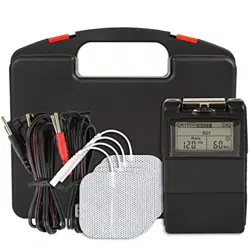
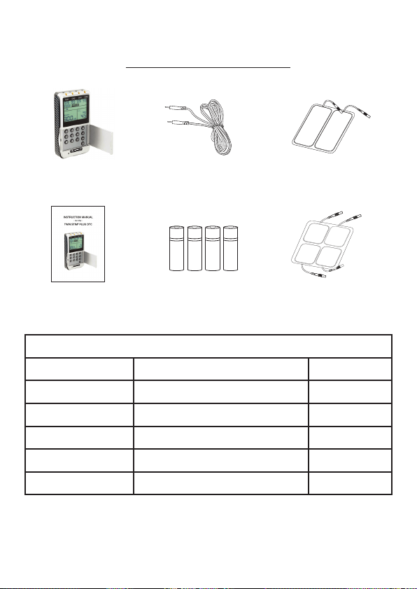
3. PACKAGE CONTENTS
Twin Stim Plus OTC
device
2 – Lead wires – 2/pk
1 – Instruction Manual 4 – AA TENS Cell
Batteries
2 – 2” x 4” electrodes
2 – 2” x 2” electrodes
REPLACEMENT PART NUMBERS
Item Number Description Qty
DS5002-OTC Twin Stim Plus OTC Device 1 each
WW3005-5PK Lead wires 2/pk 5 packs
DT7202-ELEC2416 2” x 4” Electrodes 4/pk 2 packs
DT7202-ELEC16 2” x 2” Electrodes 4/pk 2 packs
TA8222-AMZN TensCell AA Alkaline Battery 15 packs
- 14 -
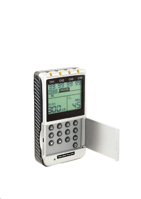
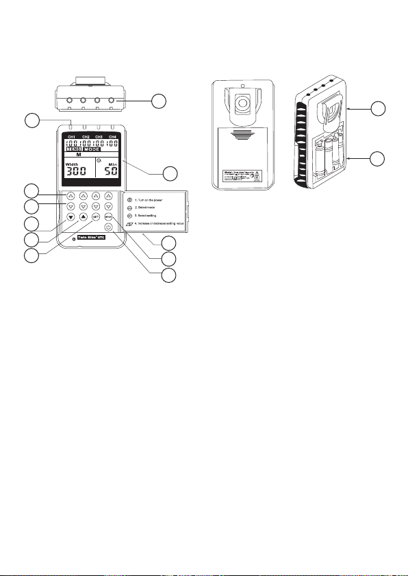
3.1 Front and Rear Panel
1) Output Sockets
2) Panel Cover
3) Liquid Crystal Display
4) Intensity Increase Control (Ch 1 – 4)
5) Intensity Decrease Control (Ch 1 – 4)
6) Mode Control
7) Set Control
8) Setting Controls - Increase
9) Setting Controls - Decrease
10) LED Output Lights
11) Belt Clip
12) Battery Case
13) Power On/Off Control
11
12
1
3
5
4
6
8
7
9
10
13
2
- 15 -
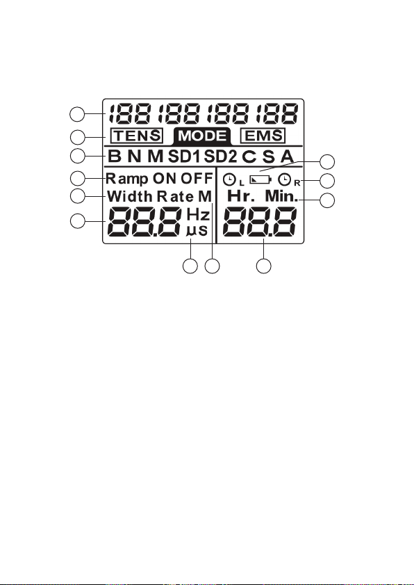
3.2 LCD Display
1) Channel Output Intensity (4 channels)
2) Waveform Display
3) Mode Display
4) Ramp/Contraction (ON)/Relaxation (OFF)
5) Pulse Width/Pulse Rate Display
6) Parameter Number Display
7) Pulse Width/Rate Measurement
8) Compliance Meter Display
9) Treatment Time Display
10) Hour/Min Display
11) Left (L) or Right (R) Timer (Left for Ch1 & Ch 2; Right for Ch3 & Ch4)
12) Low Battery Display
1
4 channel output intensity
2
TENS/EMS mode sign
3
Treatment program sign
4
Ramp/ON/OFF settings sign
5
Width/Rate settings sign
6
Parameter number display
7
Hz/us unit sign
8
Compliance meter sign
9
Treatment time display
Hour/Min unit sign
10
11
Timer sign(‘L’ for CH1
&CH2;’R’ for CH3&CH4)
12
Low battery sign
1
7 8 9
10
11
12
2
3
4
5
6

- 16 -
4. SPECIFICATIONS
4.1 Technical Information
Channel Four, isolated between channels
Power Supply Four 1.5V AA Batteries
Waveform Asymmetrical Biphasic Square Pulse
Pulse Amplitude Adjustable, 0 – 80 mA at 500-ohm load, each channel
Voltage 0 to 40V (Load: 500 ohm)
Pulse Rate Adjustable, 2 to 150 Hz (0.5 to 150 Hz for Burst Only)
Pulse Width Adjustable from 50 to 300 microseconds, 10 us/step
Contraction (ON) Time Adjustable, 2 – 60 seconds, continuous
Relaxation (OFF) Time Adjustable, 0 – 60 seconds, continuous
Ramp Time (up and
down)
Adjustable, 1 – 8 seconds
Size 5.5 in (L) x 3.1 in (W) x 1.1 in (H)
Weight 1 lb.
Operating Condition Temperature: 32° F – 104° F (0°C – 40°C)
Relative Humidity: 30% – 75%
Atmosphere Pressure: 700nPa – 1060hPa
Low Battery Indicator A low battery indicator will show up when the battery is low
Timer Two Adjustable Timers, from 1 – 60 minutes or Continuous.
Adjustable in 1 minute steps from 1 – 15 minutes and then
5 minute steps from 15 – 60 minutes. To increase or decrease
timer quicker, press and hold the increase or decrease button.
Patient Compliance
Meter
The device can store 60 sets of usage records with a total
treatment time of 999 hours.
Standard Deviation
Remark
There may be up to a +/- 5% tolerance of all parameters and
a +/- 20% tolerance of amplitude & voltage.
Service Life of the Device 3 years
Service Life of the
Electrodes
Electrodes can be cleaned and reused for up to 1~15 times
Service Life of the
Battery
New batteries will for approx. 20 times (when used for 30
minutes a day, N mode, in half of the maximum intensity).
Applied Part Electrode

- 17 -
4.2 Technical Specifications (TENS)
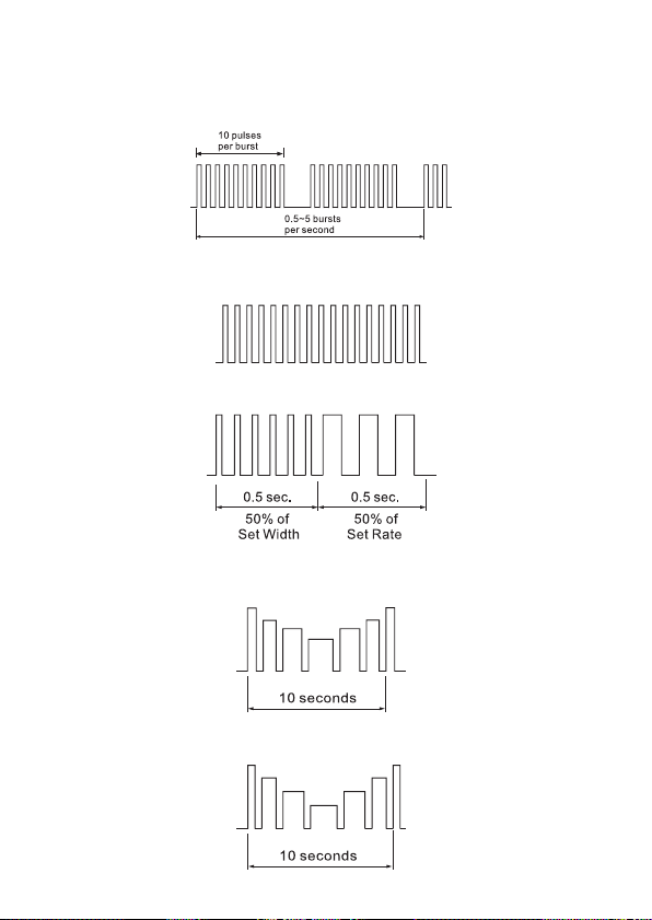
Modes (5) B (Burst), N (Normal), M (Modulation), SD1 (Strength Duration 1), SD2
(Strength Duration 2)
Burst Mode
(B)
Burst Rate: Adjustable, 0.5 – 5Hz
Pulse Width: Adjustable, 50 – 300us
Frequency: Fixed = 100 Hz
Normal
Mode (N)
The Pulse Rate and Pulse Width are adjustable. It generates continuous
stimulation based on the setting value.
Modulation
Mode (M)
The Pulse Rate and the Pulse Width modulate automatically in a varied
cycle pattern. The Pulse Width is decreased by 50% from its original
setting in 0.5 seconds, then the Pulse Rate is decreased by 50% from its
original setting in 0.5 seconds. Total cycle time is 1 second. In this mode,
Pulse Rate and Pulse Width are fully adjustable.
SD1 Mode
(SD1)
The intensity and Pulse Width automatically modulate within a 40% range.
The intensity will increase by 40% in 5 seconds while the Pulse Width will
decrease by 40% in the next 5 seconds and vice-versa. The total cycle
time is 10 seconds. Pulse Rate and Pulse Width are fully adjustable.
SD2 Mode
(SD2)
The intensity and Pulse Width automatically modulate within a 70% range.
The intensity will increase by 70% in 5 seconds while the Pulse Width will
decrease by 70% in the next 5 seconds and vice-versa. The total cycle
time is 10 seconds. Pulse Rate and Pulse Width are fully adjustable.
4.3 Technical Specifications (EMS)
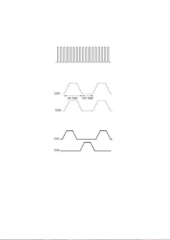
Modes (3) C (Constant), S (Synchronous), A (Alternate)
Constant
Mode (C)
This mode is based on the values of each parameter set. The Pulse Width,
Pulse Rate and Timer are adjustable in this mode. The option for Ramp,
On/Off time is not available in this mode. “Constant” is similar to “Normal”
mode of TENS waveform.
Synchro-
nous Mode
(S)
Stimulation of two channels occurs synchronously. The “ON” time
includes “Ramp Up” and “Ramp Down” time. Therefore, the setting
of “ON” time must be at least 2 x the value set for “Ramp” time. Ex: If
“Ramp” set to 8 seconds, “ON” time must be at least 16 seconds.
Alternate
Mode (A)
Stimulation of CH2 will occur after CH1 contraction is completed (same
applies for CH3 once CH4 contraction is complete). The setting of the
“ON” time must be at least 2 x the value set for the “Ramp” time and the
“OFF” time must be at least equal to the “ON” time. Ex: If “Ramp” set to 8
seconds, “ON” and “OFF” time must be at least 16 seconds.
- 18 -
4.4 Waveform Information — TENS
BURST
NORMAL
MODULATION
SD1 (STRENGTH DURATION)
SD2 (STRENGTH-DURATION)
- 19 -
4.5 Waveform Information — EMS
CONSTANT (C)
SYNCHRONOUS (S)
ALTERNATE (A)
- 20 -
5. INSTRUCTIONS FOR USE
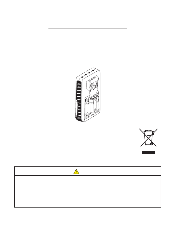
5.1 Battery
Installation of Batteries
Remove the battery cover by sliding down and removing cover.
Insert all 4 batteries with the correct polarity as shown below.
Replace battery cover.
Disposal of Battery
Depleted batteries DO NOT belong in the household waste.
Dispose of the batteries according to the your federal,
state and local regulations. As a consumer, you are
obligated by law to return depleted batteries.
CAUTION
1) Keep the battery and the product out of the range of children.
2) Battery may not be dismantled, thrown into re or short-circuited.
3) Protect battery from excess heat; Take the battery out of the product if
the product is not used for a long period of time.
4) ALWAYS replace with the same type of battery.
- 21 -
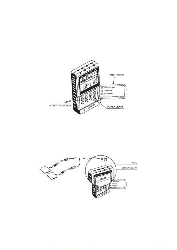
5.2 Using Your Device
A. Panel Cover
A panel on the front of the device covers all the operating buttons. To
start using the device, open the panel by putting your nger under the
panel ledge on the left side and ip it open to the left.
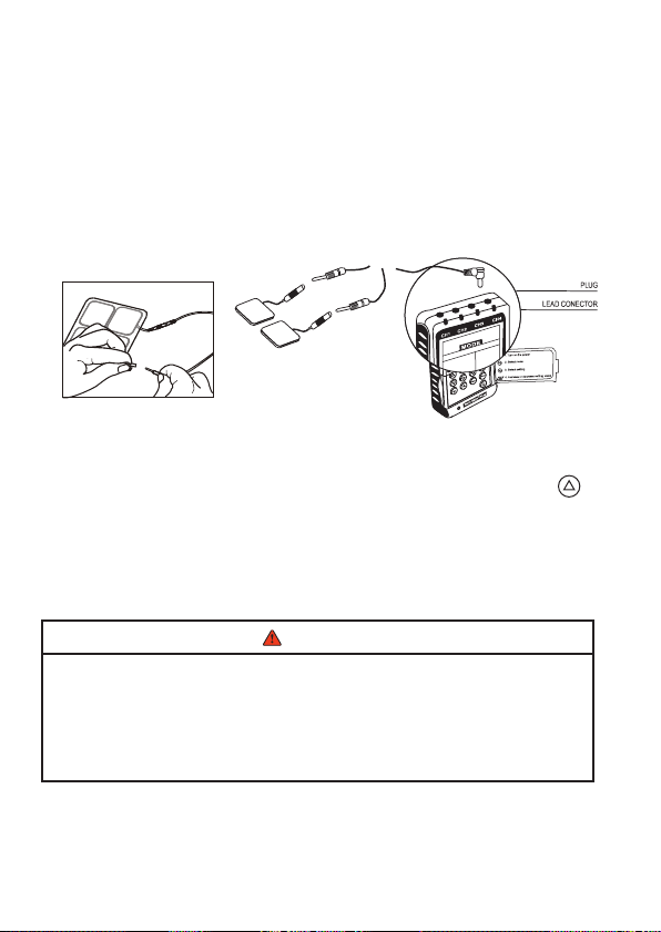
B. Connect Lead Wires
This device has four output receptacles (CH1 – CH4). Only plug into the
receptacles, the number of lead wires you will be using for treatment and
leave the other receptacles unplugged. (g. 1)
(fig. 1)
- 22 -
C. Turn on Device
Once the panel is open, press the power button. The device will beep
and the LCD screen will show a display of numbers.
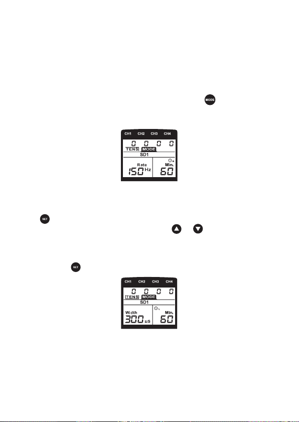
D. Select Waveform/Mode
To choose which waveform and mode to use, press until the desired
selection is displayed on the screen. There are 5 TENS modes
(B, N, M, SD1, SD2) and 3 EMS Modes (C, S, A) to choose from.
5.3 To Set TENS parameters
A. Set Pulse Width
Press button and the number for “Width” on the LCD screen will
ash. To change the default number, press or until the desired
Pulse Width number is displayed on the screen.
If the default Pulse Width is the desired number and no change is
needed, press to move on to the next parameter.
- 23 -
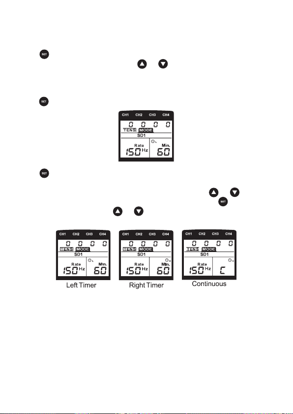
B. Set Pulse Rate
Press and the number for “Rate” on the LCD screen will ash. To
change the default number, press or until the desired Pulse Rate
number is displayed on the screen.
If the default Pulse Rate is the desired number and no change is needed,
press to move on to the next parameter.
C. Set Timer
Press again to set the timers. The LEFT (L) Timer controls CH1 &
CH2. The RIGHT (R) Timer controls CH3 & CH4 so each timer will need
to be set separately. To change the left (L) timer, press or until the
desired time is reached. If no change is necessary, press to advance
to the right (R) timer. Press or until the desired time is reached.
- 24 -
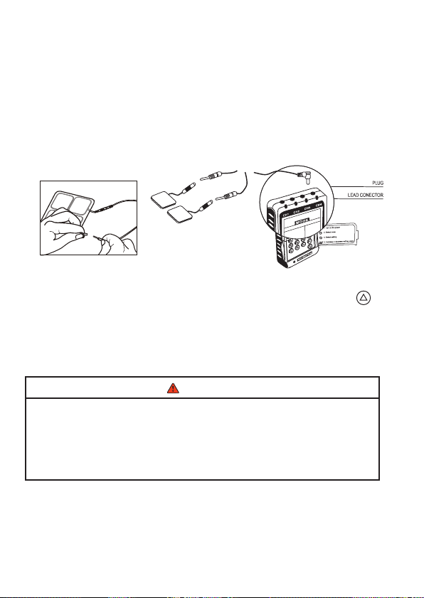
D. Connect & Place Electrodes
Once the parameters are set, connect electrodes before starting
treatment. Take the electrodes out of the sealed package. Connect
both pins of each lead wire to the pigtail of an electrode (one electrode
will not work). Make sure none of the metal pin connector is visible.
Place electrodes on or around the treatment area, ensure electrodes
are completely attached and at least 2” apart but no more than 6”
apart per channel.
E. Start Treatment
After all parameters are entered, to turn on the stimulation, press
under the corresponding channel at the top of the device being used
for therapy, until a comfortable stimulation level is reached. Repeat this
for each channel being used. Once the channel is started, the timer will
count down.
WARNING
1) Should an emergency occur and the device needs to be shut
off immediately, press the power button and the device will
completely power OFF and stop all stimulation.
2) DO NOT remove electrodes from treatment area until the
device is turned off.
- 25 -
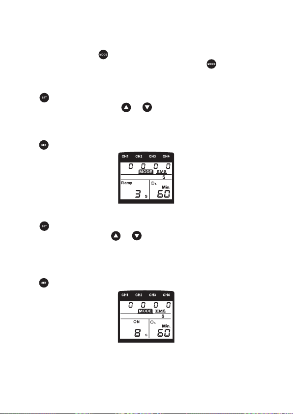
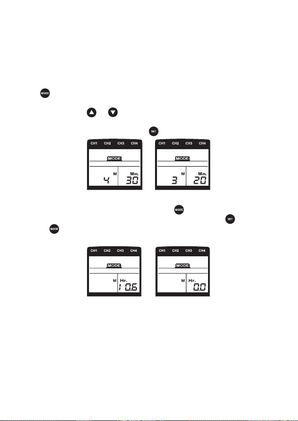
5.4 To Set EMS parameters
To choose EMS, press until EMS and “C” for Constant are displayed
on the screen. If the desired mode is “S” or “A” press until that letter
is displayed under EMS.
A. Set Ramp Up/Down Time
Press once and the number for “Ramp” on the LCD Screen will ash.
To change the number, press or until the desired ramp time is
reached.
If the default Ramp time is the desired time and no change is needed,
press to move on to the next parameter.
B. Set Contraction “ON” Time
Press and the number for “ON” on the LCD Screen will ash. To
change the number, press or until the desired contraction/”ON”
time is reached.
Note: The “ON” time must be 2 x times the “SET” number or higher.
If the default “ON” time is the desired time and no change is needed,
press to move on to the next parameter.
- 26 -
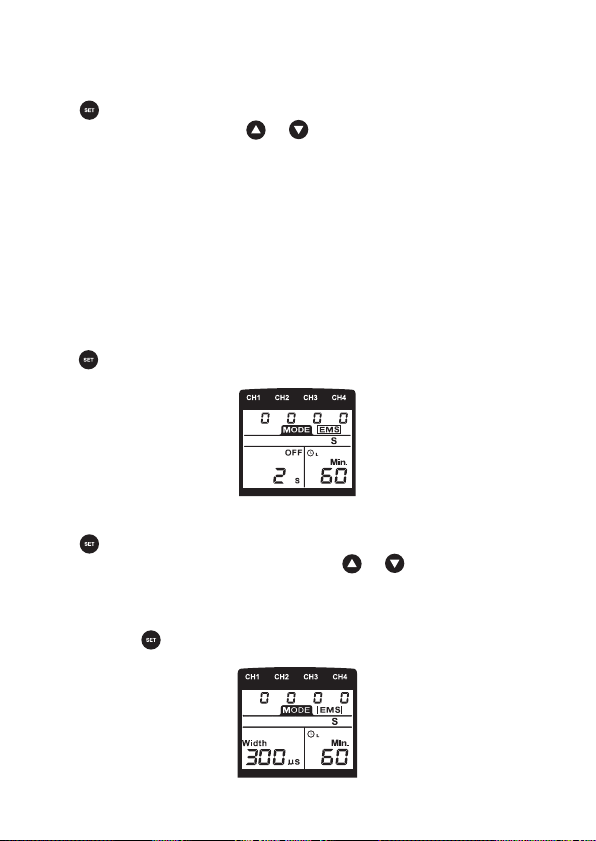
C. Set Relaxation “OFF” Time
Press button and the number for “OFF” on the LCD Screen will ash.
To change the number, press or until the desired relaxation/”OFF”
time is reached.
Note 1: For Alternate (A) Mode only, the OFF time must be at least equal
to the “ON” time or higher.
Note 2: Once treatment is started, when the device is in relaxation/”OFF”
status, the mA number under the corresponding channels will blink
during the time set. The stimulation cannot be increased during the
relaxation/”OFF” time.
If the default “OFF” time is the desired time and no change is needed,
press to move on to the next parameter.
D. Set Pulse Width
Press button and the number for “Width” on the LCD screen will
ash. To change the default number, press or until the desired
Pulse Width number is displayed on the screen.
If the default Pulse Width is the desired number and no change is
needed, press to move on to the next parameter.
- 27 -
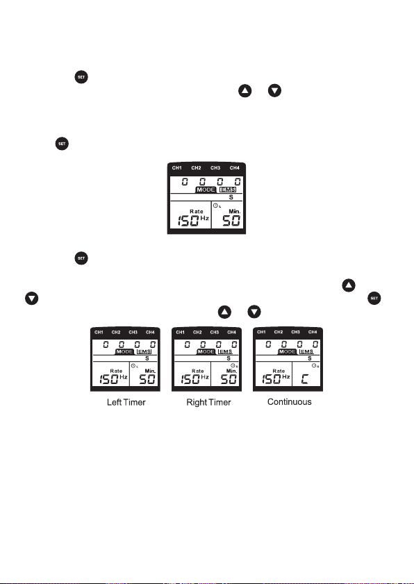
E. Set Pulse Rate
Press the button and the number for “Rate” on the LCD screen will
ash. To change the default number, press or until the desired
Pulse Rate number is displayed on the screen.
If the default Pulse Rate is the desired number and no change is needed,
press to move on to the next parameter.
F. Set Timer
Press the button again to set the timers. The LEFT (L) Timer controls
CH1 & CH2. The RIGHT (R) Timer controls CH3 & CH4 so each timer
will need to be set separately. To change the left (L) timer, press or
until the desired time is reached. If no change is necessary, press
to advance to the right (R) timer. Press or until the desired time is
reached.
- 28 -
G. Connect & Place Electrodes
Once the parameters are set, connect electrodes before starting
treatment. Take the electrodes out of the sealed package. Connect
both pins of each lead wire to the pigtail of an electrode (one electrode
will not work). Make sure none of the metal pin connector is visible.
Place electrodes on or around the treatment area, ensure electrodes are
completely attached and at least 2” apart but no more than 6” apart per
channel.
H. Start Treatment
After all parameters are entered, to turn on the stimulation, press
under the corresponding channel at the top of the device being used
for therapy, until a comfortable stimulation level is reached. Repeat this
for each channel being used. Once the channel is started, the timer will
count down.
WARNING
1) Should an emergency occur and the device needs to be shut
off immediately, press the power button and the device will
completely power OFF and stop all stimulation.
2) DO NOT remove electrodes from treatment area until the
device is turned off.
- 29 -
5.5 Check Compliance Meter
The compliance meter can store 60 sets of records with a total treatment
time of 999 hours.
A. Check & Delete Individual Records
Press and the power button at the same time. The screen will show
the number of recorded treatments and total operation time. To see
each record, press or to check each record.
To delete an individual record, press button and hold for 3 seconds.
B. Check & Delete Accumulative Record
When in the individual records menu, press to switch to
accumulative records menu. To delete ALL records, press rst,
then the button simultaneously for 3 seconds and ALL records
will be deleted followed by a beeping sound.
5.6 Check/Replace Batteries
Over time, in order to ensure the functional safety of the device,
changing the batteries is necessary.
• Make sure that all four channels at the top of the device, read 0 or .
device is completely shut off.
• Follow the steps on page 20 to insert new batteries.

- 30 -
6. CLEANING AND STORAGE
6.1 Keeping Electrodes Clean
• Ensure the device is completely turned off when removing the
electrodes from the treatment area.
• Disconnect the electrodes from each lead wire and place on protective
liner supplied with the electrodes.
• If electrodes are difcult to attach to the skin or the protective liner,
they may be able to be reconstituted for one more use prior to
replacing with new electrodes.
• Place a small drop of water on your cleaned ngertip and rub the
water across the entire gel part. Place the electrode gel part, face
up and let it air dry until the water is absorbed and reconstituted. This
can only be done once and then the electrodes need to be replaced.
• DO NOT wipe with a tissue or cloth. If the electrodes are still not
sticking completely to the treatment area without any lifting, they
MUST be replaced with new electrodes.

- 31 -
CAUTION
1. The life of electrodes is dependent on many factors including, but not limited to,
cleanliness of treatment area, oiliness of skin, amount of hair, increased sweating,
storage state, etc.
2. If the electrodes are lifting or no longer stick to the treatment area, they MUST be
replaced to avoid sudden shock or possible burns on any of the applied electrodes,
including the electrodes adhered correctly and completely.
3. Before applying self-adhesive electrodes, it is recommended to wash the area with
mild soap and water, completely drying the treatment area before placement.
4. NEVER remove the electrodes while the device is turned on.
5. It is recommended to use the same size electrodes that are supplied with the device
for replacement electrodes. Electrodes smaller than those provided may increase the
chance of skin irritation or electrode burns. Electrodes larger than those provided
may reduce the effect of stimulation, which could result in a false need to increase the
intensity resulting in electrode burns or shocks.
6. If replacement electrodes are necessary, use only electrodes that are the same size
(2” x 2”, 2” x 4” & 3” Round) as the electrodes provided with the Twin Stim Plus OTC.
7. Use of larger electrodes may reduce the effect of the stimulation.
Use of electrodes that are much smaller than the electrodes provided
with the Twin Stim Plus OTC may increase the chance of skin irritation or electrode
burns occurring under the electrodes.
8. ALWAYS use electrodes that have been cleared for marketing in the
USA by the FDA.
6.2 Storing Device, Electrodes and Lead Wires
• After electrodes have been removed from treatment site and
discon nected from lead wires, place electrodes on the plastic liner
and store in a resealable package.
• Wrap lead wires and store in a resealable package.
• If device is not being used for long periods of time, remove batteries
from device before storing.
• Place the batteries, device, electrodes and lead wires back into the
carrying case. Store in a cool, dry place ranging from 14°F – 131°F
(-10°C – 55°C) with a relative humidity of 10% – 90%.
DO NOT keep in places that can be easily reached by children.

- 32 -
7. TROUBLESHOOTING
Problem Possible Causes Possible Solution
The device cannot
power on
Are the batteries
depleted?
Replace the batteries.
Are the batteries installed
correctly?
Insert the batteries
observing polarity.
Stimulation weak
or cannot feel any
stimulation
Electrodes dried out or
contaminated
Replace with new
electrodes
Electrodes are not securely
attached to the skin.
Reconnect the electrodes
Lead wires
Old/worn/damaged
Replace with new
lead wires
Stimulation is
uncomfortable
Intensity is too high Decrease intensity.
Electrodes are too close
together
Reposition the electrodes
at least 2” apart and no
more than 6” per channel.
Electrode active area size
is too small.
Replace electrodes with
ones that have an active
area no less than 2” x 2”.
May not be operating the
device according to the
manual.
Please check the manual
before use
Intermittent output Lead wires
Verify connection is
secure.
Turn down the intensity.
Rotate lead wires in socket
90°. If still intermittent,
replace lead wire.
If still intermittent after
replacing lead wire, a
component may have
failed. Call the repair
department.

- 33 -
7. TROUBLESHOOTING (Continued)
Problem Possible Causes Possible Solution
Stimulation is
ineffective.
Improper electrode
placement
Reposition the electrodes
at least 2” apart and no
more than 6” per channel.
Unknown Consult clinician.
The skin becomes
red and/or you feel
a stabbing pain
Using the electrodes on the
same site every time.
Re-position the
electrodes. If at any time
you feel pain or discomfort
stop use immediately.
The electrodes aren’t stuck
onto the skin properly
Ensure the electrodes
are stuck securely on
the skin.
The electrodes are dirty.
Clean the electrodes
according to description
in this manual or replace
with new electrodes.
The surface of the electrode
was scratched.
Replace with a new
electrode.
Output current
stops during
therapy
The electrodes are not
connected to the skin
properly.
Turn off the device and
place the electrodes again.
The lead wires are
disconnected
Turn off the device and
reposition the lead wires.
The power of the batteries
has been depleted.
Charge or replace the
batteries.
- 34 -
8. DISPOSAL
Used fully discharged batteries MUST be disposed of in
a specially labeled collection container, at toxic waste
collection points or through an electrical retailer. You are
under legal obligation to dispose of batteries correctly.
Please dispose of the device in accordance with the
legal obligation.
9. GLOSSARY OF SYMBOLS
Electrical devices are recyclable material and should not
be disposed of with household waste after their useful life!
Help us to protect the environment and save resources
and take this device to the appropriate collection points.
Please contact the organization which is responsible for
waste disposal in your area if you have any questions.
Type BF Applied Part
Please refer to instruction manual.
Caution

- 35 -
10. ELECTROMAGNETIC COMPATIBILITY
(EMC) TABLES
• This device should not be used adjacent to or stacked with other
equipment. If adjacent or stacked use is necessary, this device should
be observed to verify normal operation in the conguration in which it
will be used
• Use of accessories other than those specied or provided by the
manufacturer of this device could result in increased electromagnetic
emissions or decreased electromagnetic immunity of this equipment
and result in improper operation.
• Portable RF communications equipment (including peripherals
such as antenna cables and external antennas) should be used
no closer than 30 cm (12 inches) to any part of the device, including
cables specied by the manufacturer. Otherwise, degradation of the
performance of this equipment could result.
• When the operating environment is relatively dry, strong
electromagnetic interference usually occurs. At this time, the device
may be affected as follows:
- the device stops output;
- the device turns off;
- the device restarts;
• The above phenomenon does not affect the basic safety and
essential performance of the device, and the user can use it
according to the instruction. If you want to avoid the above
phenomenon, please use it according to the environment specied in
the manual.

- 36 -
TABLE 1
Declaration - electromagnetic emission
The device is intended for use in the electromagnetic environment specied below. The customer or the
user of device should assure that it is used in such an environment.
Emissions test Compliance Electromagnetic environment - guidance.
RF emissions
CISPR 11
Group 1 The device uses RF energy only for its internal
function. Therefore, its RF emissions are very
low and are not likely to cause any interference
in nearby electronic equipment.
RF emissions
CISPR 11
Class B The device is suitable for domestic
establishment and in establishment directly
connected to the public low-voltage power
supply network that supplies buildings used for
domestic purposes.
Harmonic emissions
IEC 61000-3-2
Not applicable
Voltage uctuations/
icker emissions
IEC 61000-3-3
Not applicable

- 37 -
TABLE 2
Declaration - electromagnetic immunity
The device is intended for use in the electromagnetic environment specied below. The customer or the
user of device should assure that it is used in such an environment.
Immunity test IEC 60601 test
level
Compliance level Electromagnetic environment -
guidance
Electrostatic
discharge (ESD)
IEC 61000-4-2
±8 kV contact
±2 kV, ±4 kV, ±8
kV, ±15 kV air
±8 kV contact
±2 kV, ±4 kV, ±8
kV, ±15 kV air
Floors should be wood, concrete
or ceramic tie. If oors are covered
with synthetic material, the relative
humidity should be at least 30 %.
Electrical fast
transient/
burst
IEC 61000-4-4
± 2 kV for power
supply lines
± 1 kV for input/
output lines
Not applicable Mains power quality should be that
of a typical commercial or hospital
environment.
Surge
IEC 61000-4-5
± 0.5kV, ± 1 kV
line(s) to lines
± 0.5kV, ± 1 kV,
± 2 kV line(s) to
earth
Voltage dips, short
interruptions and
voltage variations
on power supply
input lines
IEC 61000-4-11
0 % UT; 0.5 cycle
At 0°, 45°, 90°,
135°, 180°, 225°,
270° and 315°
0 % UT; 1 cycle
and 70 % UT;
25/30 cycles
Single phase:
at 0°
0 % UT; 250/300
cycles
Not applicable Mains power quality should be that
of a typical commercial or hospital
environment. If the user of the
device requires continued operation
during power mains interruptions,
it is recommended that the device
be powered from an uninterruptible
power supply or a battery.
Power frequency
(50/60 Hz)
magnetic eld
IEC 61000-4-8
30 A/m 30 A/m Power frequency magnetic elds
should be at levels characteristic
of a typical location in a typical
commercial or hospital environment.
NOTE: UT is the a.c. mains voltage prior to application of the test level.

- 38 -
TABLE 3
Declaration - electromagnetic immunity
The device is intended for use in the electromagnetic environment specied below. The customer or the
user of device should assure that it is used in such an environment.
Immunity test IEC 60601
test level
Compliance
level
Electromagnetic environment - guidance
Conducted RF
IEC 61000-4-6
3V
0.15 MHz to
80MHz
6 V in ISM
and amateur
radio bands
between
0.15 MHz
and 80
MHz
Not
applicable
Portable and mobile RF communications equipment
should be used no closer to any part of device, than
the recommended separation distance calculated
from the equation applicable to the frequency of the
transmitter. Recommended separation distance
Radiated RF
IEC 61000-4-3
10 V/m
80 MHz to
2.7 GHz
10V/m d=1.2√P
150 KHz to 80 MHz
d=1.2√P
80 MHz to 800 MHz
d=2.3√P
80 MHz to 2.7 GHz
Where P is the maximum output power rating of the
transmitter in watts (W) according to the transmitter
manufacturer and d is the recommended separation
distance in meters (m).
Field strengths from xed RF transmitters, as
determined by an electromagnetic site survey, a
should be less than the compliance level in each
frequency range.
Interference may occur in the vicinity of
equipment marked with the following symbol:
NOTE 1: At 80 MHz and 800 MHz, the higher frequency range applies.
NOTE 2: These guidelines may not apply in all situations. Electromagnetic propagation is affected by
absorption and reection from structures, objects and people.
a. Field strengths from xed RF transmitters, such as base stations for radio (cellular/cordless) telephones
and land mobile radios, amateur radio, AM and FM radio broadcast and TV broadcast cannot be predicted
theoretically with accuracy. To assess the electromagnetic environment due to xed RF transmitters, an
electromagnetic site survey should be considered. If the measured eld strength in the location in which
device is used exceeds the applicable RF compliance level above, device should be observed to verify
normal operation. If abnormal performance is observed, additional measures may be necessary, such as
re-orienting or relocating device.
b. Over the frequency range 0.15 MHz to 80 MHz, eld strengths should be less than 3 V/m.
- 39 -
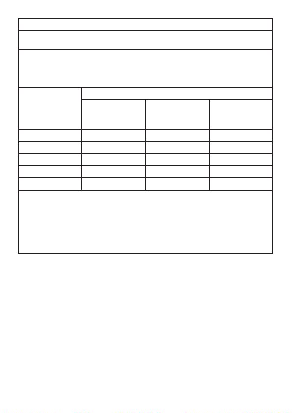
TABLE 4
Recommended separation distances between portable and mobile RF communications equipment and
device
The device is intended for use in an electromagnetic environment in which radiated RF disturbances
are controlled. The customer or the user of device can help prevent electromagnetic interference
by maintaining a minimum distance between portable and mobile RF communications equipment
(transmitters) and device, as recommended below, according to the maximum output power of the
communications equipment.
Rated maximum output
power of transmitter W
Separation distance according to frequency of transmitter m
0.15 MHz to 80 MHz
d=1.2√P
80 MHz to 800 MHz
d=1.2√P
80 MHz to 2.7 GHz
d=2.3√P
0.01 0.12 0.12 0.23
0.1 0.38 0.38 0.73
1 1.2 1.2 2.3
10 3.8 3.8 7.3
100 12 12 23
For transmitters rated at a maximum output power not listed above, the recommended separation
distance d in meters (m) can be estimated using the equation applicable to the frequency of the
transmitter, where P is the maximum output power rating of the transmitter in watts (W) according to the
transmitter manufacturer
NOTE 1: At 80 MHz and 800 MHz, the higher frequency range applies.
NOTE 2: These guidelines may not apply in all situations. Electromagnetic propagation is affected by
absorption and reection from structures, objects and people.

- 40 -
11. WARRANTY
All Twin Stim
®
PLUS OTC models carry a warranty of one year from
the date of delivery. The warranty applies to the stimulator only and
covers both parts and labour relating thereto. The warranty does
not apply to damage resulting from failure to follow the operating
instructions, accidents, abuse, alteration or disassembly by
unauthorized personnel.
1) The warranty period for device is one year from date of purchase.
In case of a warranty claim, the date of purchase has to be proven
by means of the sales receipt or invoice.
2) Repairs or replacement under warranty DO NOT extend the warranty
period either for the device or for the replacement parts.
3) The following is excluded under the warranty:
• All damage which has arisen due to improper treatment, e.g.
nonobservance of the user instruction.
• All damage which is due to repairs or tampering by the customer or
unauthorized third parties.
• Damage which has arisen during transport from the manufacturer to
the consumer or during transport to the service center.
• Accessories included with the device.
4) Liability for direct or indirect consequential losses caused by the
device is excluded even if the damage to the device is accepted as a
warranty claim.

- 41 -

Manufactured for:
Compass Health Brands
6753 Engle Rd
Middleburg Heights, OH 44130
www.compasshealthbrands.com
800.871.7858
2040.19.05.A