Loading ...
Loading ...
Loading ...
INSTALLATION
Check the appliance is electrically safe and gas sound when you have nished.
37
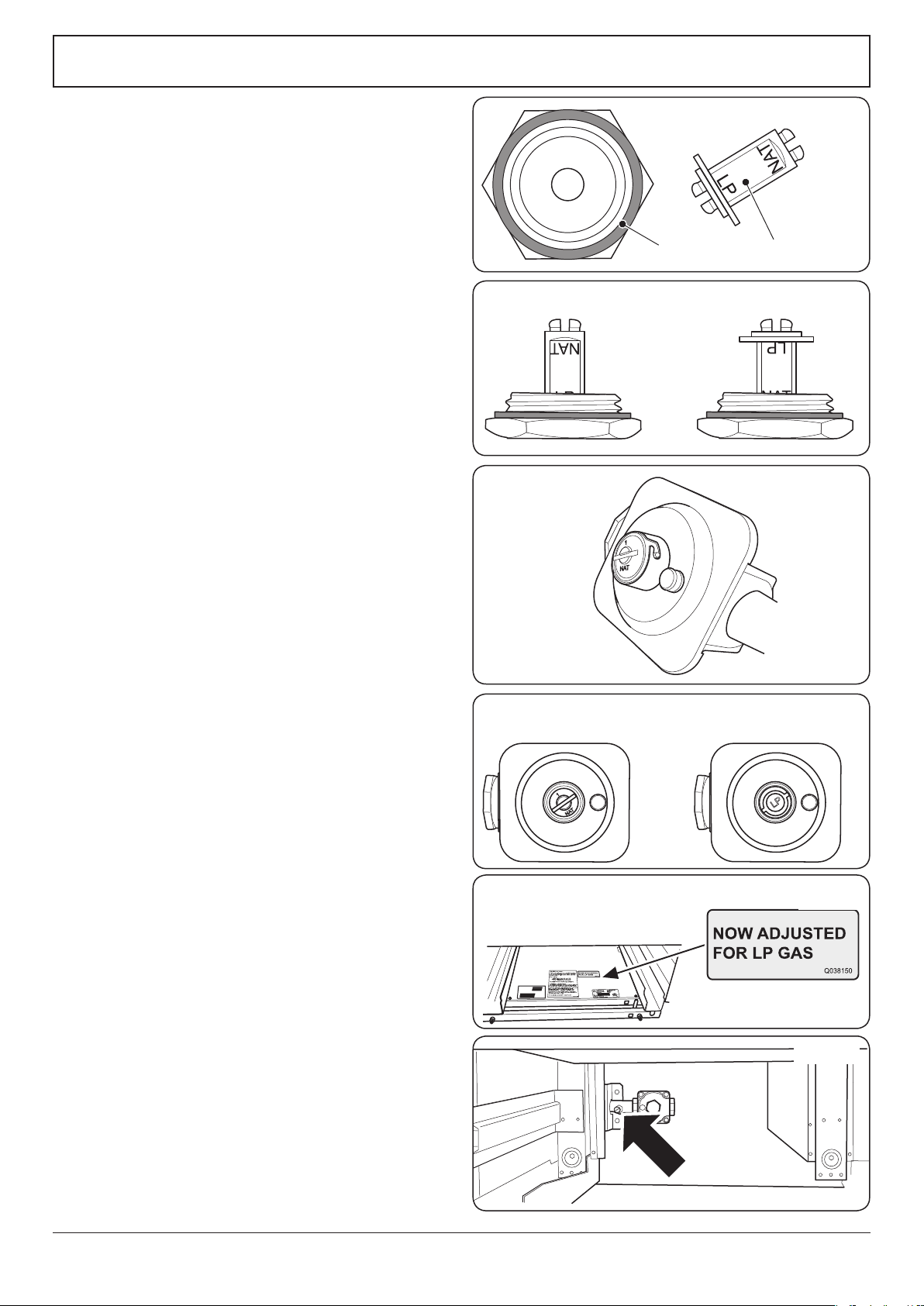
Type 1
Unscrew the hexagonal nut in the front of the regulator. The
regulator nut has a plastic snap-in converter device on the
underside (Fig. 7.5). To convert the regulator snap the device
out of the nut and replace the other way up.
The snap-in converter device is marked to show which gas it
is set for (Fig. 7.6). Make sure the device is secure in the base
of the nut and replace the nut to the regulator.
Type 2
The regulator has a bayonet mounted top cap (Fig. 7.7).
Using a small coin, press in and turn the cap to remove it.
Turn the cap over so that the letters “LP” are visible on base of
the hollow in the cap. Replace the cap making sure that the
bayonet pins are securely located (Fig. 7.8).
Stick on Label
Stick the “NOW ADJUSTED FOR LP GAS” label next to the
ratings label inside the drawer cavity to indicate the gas the
appliance is now set for (Fig. 7.9).
Pressure Testing
Connect the appliance to the gas supply. Check the appliance
is gas sound.
The gas pressure can be measured at the pressure test point
on the appliance side of the pressure regulator (Fig. 7.10).
For proper operation, the pressure of LP supplied to the
regulator must be between 10’’ and 13’’ of water column
(2.49–3.24 kPa).
When checking for proper operation of the regulator, the
inlet pressure must be at least 1’’ (0.25 kPa) greater than the
operating (manifold) pressure as given above.
The pressure regulator located at the inlet of the range
manifold must remain in the supply line regardless of
whether natural or LP gas is being used.
Check the appliance is gas sound.
DO NOT use a ame to check for gas leaks.
When using test pressures greater than ½ psig to pressure
test the gas supply system of the residence, disconnect the
range and individual shut-o valve from the gas supply
piping. When using test pressures of ½ psig or less to test
the gas supply system, simply isolate the range from the gas
supply system by closing the individual shut-o valve.
Check the operation of all the burners.
ArtNo.102-0007 - Maxitrol converter device positions
ArtNo.103-0006 - Maxitrol cap & converter
Nut
Snap-in converter device
ArtNo.102-0008 - Regulator cap
ArtNo.102-0010 - Adjusted to LP gas label
ArtNo.102-0009 - Gas regulator settings
Type 1 Type 2
Fig. 7.5
Fig. 7.6
Fig. 7.7
Fig. 7.8
Fig. 7.9
ArtNo.102-0011 - Pressure test point
Fig. 7.10
Loading ...
Loading ...
Loading ...