
ContactDetails
Pleasenotethatsomeofthecontactdetailson
thisPDFdocumentmaynotbecurrent.
Pleaseusethefollowingdetailsifyouneedto
contactus:
Telephone:08448793588
Email:[email protected]
Thecustomersupportsectionofourwebsitealsofeaturesawide
rangeofinformationwhichmaybeofusetoyouandisavailable
24hoursaday.Itincludes:
• Operatingandinstallationinstructions
• Easy‘Howtouse’guidesforstorageheaters
• Serviceandrepairs
• Where
tobuyourproducts
• Literaturedownloads
• Heatingrequirementcalculator
Visit‐www.dimplex.co.uk/support
A division of GDC Group Ltd
Millbrook House Grange Drive Hedge End Southampton SO30 2DF
www.dimplex.co.uk
Re
g
istered No: 1313016 En
g
land
VAT GB 287 1315 50004
EEE Producer Registration Number –
WEE/GE0057TS
Paper from sustainable sources

08/50288/2 (UK) Issue 2
BIZET BZT20
The product complies with the European Safety Standards EN60335-2-30 and the European Standard Electromagnetic Compatibility (EMC) EN55014, EN60555-2
and EN60555-3. These cover the essential requirements of EEC Directives 2006/95/EC and 2004/108/EC
1
I
1
2
3
T
1
2
2
4
3
5
7
6
1
2
3
4
621
750
183
300 Min.
600 Recommended
160
160
200
1130 Recommended
A
B
C
D
E
A B C D E
580 580 459 608 40

Important Safety Advice
When using electrical appliances, basic precautions
sh
ould be followed to reduce the risk of fire, electric
shock, a
nd injury to persons, including the following:
If t
he appliance is damaged, check immediately with the
supplier b
efore installation and operation.
Do n
ot use this heater in the immediate surroundings of
a b
ath, shower or swimming pool
.
Do not use outdoors.
This he
ater must not be located immediately above or
bel
ow a fixed socket outlet or connection box.
Do n
ot cover or obstruct in any way the heat outlet grille
located underneath the heater. Overheating will result if
the he
ater is accidentally covered.
In t
he event of a fault unplug the heater.
Un
plug the heater when not required for long periods.
The supply cord must be placed on the right hand side of
t
he h
eater away from the heat outlet underneath the
he
ater.
Although t
his heater complies with safety standards, we
do n
ot recommend its use on deep pile carpets or on
long h
air type of rugs.
This a
ppliance is not intended for use by children or other
persons w
ithout assistance or supervision if their
physic
al, sensory or mental capabilities prevent them
from usi
ng it safely. Children should be supervised to
ensure t
hat they do not play with the appliance.
The a
ppliance must be positioned so that the plug is
accessible.
If the su
pply cord is damaged it must be replaced by the
manufacturer o
r service agent or similarly qualified
person in order to avoid a hazard.
Caution: In order to avoid a hazard due to inadvertent
resetting of the thermal cut-out, this appliance must not
be supplied through an external switching device, such
a
s a tim
er, or connected to a circuit that is regularly
switched o
n and off by the utility.
The appliance must not to be located beneath a socket
o
utlet.
W
here a
n appliance is Recessed, necessity to allow
disconnection o
f the appliance from the electrical supply
is r
equired. Incorporate a switch in the fixed wiring in
accordance w
ith the Wiring regulations.
General
Unpack the heater carefully and retain the packaging for
possible future use, in the event of moving or returning the fire
to your supplier.
The fire incorporates a flame effect, which can be used with or
without heating, so that the comforting effect may be enjoyed at
a
ny t
ime of the year. Using the flame effect on its own only
requires little electricity.
Before connecting the heater check that the supply voltage is
the same as that stated on the heater.
Please note: Used in an environment where background noise
is very low, it may be possible to hear a sound which is related
to the operation of the flame effect. This is normal and should
not be a cause for concern.
Electrical
WARNING – THIS APPLIANCE MUST BE EARTHED
Th
is heater must be used on an AC ~ supply only and the
voltage marked on the heater must correspond to the supply
voltage.
Do not switch the appliance on until properly installed.
Please
read all the safety warnings and operating instructions.
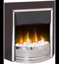
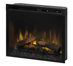
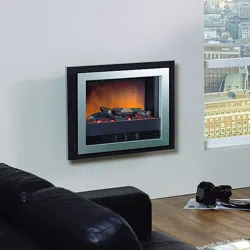
Bizet BZT20 Wall Fire
IMPORTANT: THESE INSTRUCTIONS SHOULD BE READ CAREFULLY AND RETAINED FOR FUTURE REFERENCE
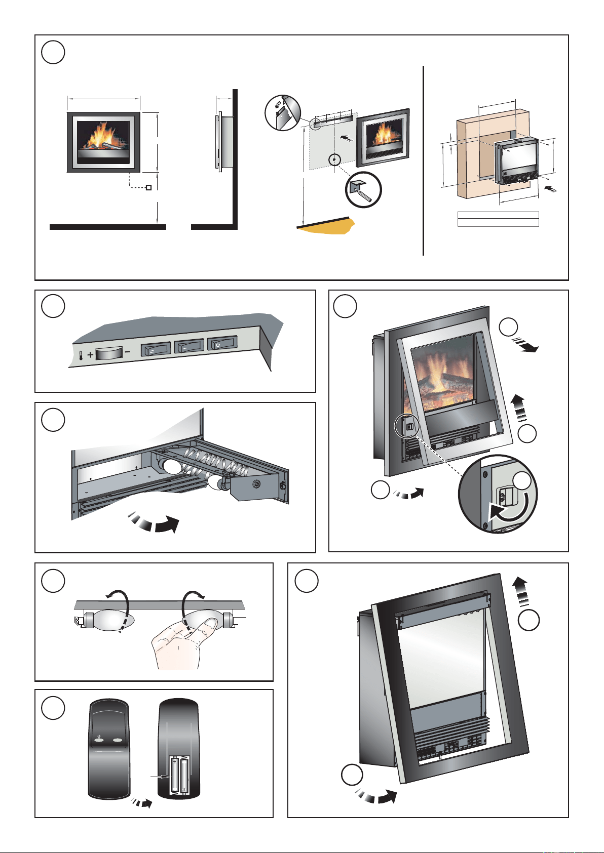
Wall fixing - see Fig. 1
The appliance should be securely fixed to the wall using the
wall plugs and screws supplied for block walls.
N
ote – f
or studded walls special fasteners are required, see
diagram for recommended position of fixing screws.
Recessed Installation
Please note that this appliance can also be wall-mounted so
th
at it is recessed. This can be installed in a large fireplace
opening or a purpose built wall. See Fig. 1 for size of recess
required and hole fixing dimensions.
This fireplace insert does
NOT require venting.
In order to ensure it’s future safety in use, it is essential that
this fire is securely fixed
to the wall.
IT IS IMPORTANT THAT THE FIXING DEVICE CHOSEN IS
A
PPROP
RIATE TO THE WALL MATERIAL TO WHICH THE FIRE
IS B
EING FIXED. SOME MODERN INTERNAL BUILDING
MAT
ERIALS ARE VERY LOW DENSITY BLOCK AND REQUIRE
SPECI
ALIZED FIXING DEVICES TO PROVIDE A SAFE,SECURE
INSTA
LLATION.
The installation of this fire should be carried out by a competent
person. If in doubt please consult your local builder.
This section provides step by step instructions for selecting a
location and preparing the site to install the fireplace into the
f
ollowing:
Existing Fireplace
1. Make sure that the fire is located on a flat surface.
2. Seal all draughts and vents to prevent chimney debris from
f
alling o
nto the Fireplace Insert. Do not install into an existing
fireplace that is prone to dampness.
3. Remove the front/trim by following the steps as outlined in
‘
Lamp R
eplacement’ section.
4. Locate the 4 fixing holes, position the fire accordingly, and
f
irmly f
ix the appliance to the wall using the appropriate
screws.
5. Replace the front/trim.
New Support Structure Construction
When planning where to position your purpose built support
structure the following steps must be observed:
1.
Place the fire in the desired location to see how it will look in
the room.
2.
Mark the desired location for the new support structure in
t
he r
oom and store the fire in a safe, dry and dust free
locati
on.
3. Using timber studs to support the fire, devise and construct
a suitable means of supporting the product within the wall
partition and provide electrical power for the fire to be HARD
wired. For recommended sizes of height, width and depth
of opening for recess and hole fixing dimensions for each
model - see Fig. 1.
4. R
emove the front/trim by following the steps as outlined
previously.
5. Locate the 4 fixing holes, position the fire accordingly, and
firmly fix using the appropriate screws.
6. Replace the front/trim.
NOTE: The appliance should be HARD wired to an electrical
power outlet when placed in a recessed installation.
Please c
onsult a qualified electrician for appropriate wiring
requirements.

Controls - see Fig. 2
Thermostat (T) - see Fig. 2
In order to maintain a certain room temperature, set the
controller to ‘max.’. Operate the appliance at full power until the
required room temperature is reached. Set back the
thermostatic controller until the appliance switches off with an
audible ‘click’. This temperature will be kept almost constant
by the thermostatic control switching on and off automatically.
Please note that the appliance can only be switched on when
the thermostat setting is higher then the room temperature.
Remote control - see Fig. 7
The maximum range of use is ~ 15metres.
Warning: It takes time for the receiver to respond to the
transmitter.
Do not press the buttons more than once within two seconds
for correct operation.
Battery information - see Fig. 7
1. Slide open the battery cover on the back of the remote
control
2. Install AAA batteries into the remote control
3. Replace the battery cover.
Discard leaky batteries
Dispose of batteries in the proper manner according to
provincial and local regulations.
Any battery may leak electrolyte if mixed with a different battery
type, if
inserted incorrectly,
if all the batteries are not replaced at
the same time, if disposed of in a fire, or if an attempt is made
to charge a battery not intended to be recharged.
Thermal Safety Cut-out
A thermal safety cut-out is incorporated in the heater to prevent
damage due to overheating. This can happen if the heat outlet
was restricted in any way. The heater will switch on once the
obstruction has been removed and the heater has cooled. If
the cut-out continues to operate intermittently, the heater should
be switched off and a service agent contacted.
Maintenance
WARNING: ALWAYS DISCONNECT FROM THE POWER SUPPLY
BEFORE ATTEMPTING ANY MAINTENANCE.
Lamp Replacement - see Fig. 3, Fig. 4 and Fig. 5
Remove front cover.
Using a coin edge or screwdriver turn catch 1/4 turn clockwise
Pull the tray forward, the bulbs can now be replace with a 60W
E14 SES Clear Candle lamp.
Take care not to over-tighten the lamp
Trim colour options – see Fig. 6
The fire comes with a reversible trim.
Cleaning
WARNING – ALWAYS DISCONNECT FROM THE POWER
SUPPLY BEFORE CLEANING THE HEATER.
For general cleaning use a soft
clean duster – never use
abrasive cleaners. The glass viewing screen should be
cleaned carefully with a soft cloth. DO NOT use proprietary
glass cleaners.
To remove any accumulation of dust or fluff the soft brush
attachment of a vacuum cleaner should occasionally be used
to clean the outlet grille of the fan heater.
Recycling
For electrical products sold within the European Community.
At the end of the electrical products useful life it
should not be disposed of with household waste.
Please recycle where facilities exist. Check with your
Local Authority or retailer for recycling advice in your
country.
After Sales Service
Your product is guaranteed for one year from the date of
purchase.
Within this period, we undertake to repair or exchange this
product free of charge (excluding lamps & subject to availability)
provided it has been installed and operated in accordance
with these instructions.
Your rights under this guarantee are additional to your statutory
rights, which in turn are not affected by this guarantee.
Should you
require after
sales service you should contact our
customer services help desk on 0845 600 5111. It would assist
us if you can quote the model number, series, date of purchase,
and nature of the fault at the time of your call. The customer
services help desk will also be able to advise you should you
need to purchase any spares.
Please do not return a faulty product to us in the first instance
as this may result in loss or damage and delay in providing you
with a satisfactory service.
Please retain your receipt as proof of purchase.
Three switches provide a choice of heat settings. The appliance is in
standby mode when the mains lead is plugged in. This is indicated by
the red neon behind the flame effect screen. The two selector switches
are in the ON position when the side with the markings on (i.e. I, or II)
are pushed in.
Push button switch 1 Controls the electricity supply to the heater
and flame effect. Press for ‘ON’ and
‘Standby’. If both selector switches 2 and
3 are in the OFF position, the product
works on flame effect only.
Selector switch 2 (I) Provides 1kW heat output
Selector switch 3 (II) Provides 2kW output with switch 2
Dimplex UK Limited
Millbrook House
Grange Drive
Hedge End
Southampton
Hampshire. SO30 2DF
[c] Dimplex UK Limited
All rights reserved. Material contained in this publication may not be reproduced in whole or in part, without prior permission in writing of Dimplex UK Limited.
UK customer help line 08.30–17.00 Mon-Thurs and 08:30-16.00 Fri (Sept–May)
08.30–17.00 Mon-Thurs and 08:30-15.00 Fri (Jun–Aug)
Technical Services: Tel. 0845 600 5111
Fax. 01489 773053
e-mail [email protected]k
Republic of Ireland Tel. 01 8424833